Data sheet Thermostat RT -...
16
© Danfoss | DCS (az) | 2017.10 IC.PD.P10.1E.02 | 520B8147 | 1 RT thermostats incorporate a temperature controlled, single-pole change over switch where the contact position depends on the temperature of the sensor and the set scale value. The RT series consists of thermostats with room sensors, duct sensors and capillary tube sensors for general industrial and marine applications. Features • Simple design. • High accuracy. • High repeatability. • Long operation life time. • Available with all major marine approvals. • Safety Integrity Level: SIL 2 according to IEC 61508. Data sheet Thermostat RT
Transcript of Data sheet Thermostat RT -...

© Danfoss | DCS (az) | 2017.10 IC.PD.P10.1E.02 | 520B8147 | 1
RT thermostats incorporate a temperature controlled, single-pole change over switch where the contact position depends on the temperature of the sensor and the set scale value.
The RT series consists of thermostats with room sensors, duct sensors and capillary tube sensors for general industrial and marine applications.
Features • Simple design.• High accuracy.• High repeatability.
• Long operation life time.• Available with all major marine approvals.• Safety Integrity Level:
SIL 2 according to IEC 61508.
Data sheet
Thermostat RT
© Danfoss | DCS (az) | 2017.10
Data sheet | Thermostat, RT
IC.PD.P10.1E.02 | 520B8147 | 2
RT 2RT 23RT 26
RT 108
RT 4RT 11
RT 16LRT 17
RT 140L
RT 3RT 7RT 8
RT 8LRT 9
RT 12RT 13RT 14
RT 14LRT 15
RT 16RT 102RT 141
RT 34RT 103RT 115RT 140
RT 101RT 106RT 107RT 123
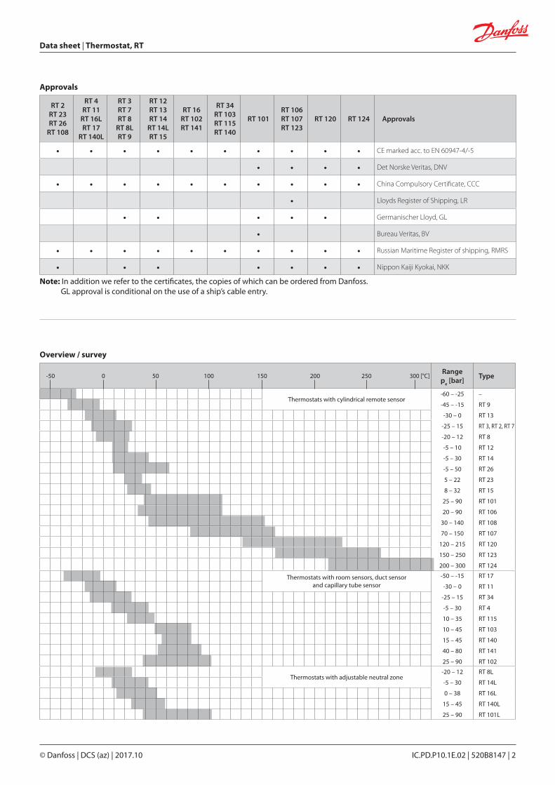
RT 120 RT 124 Approvals
• • • • • • • • • • CE marked acc. to EN 60947-4/-5
• • • • Det Norske Veritas, DNV
• • • • • • • • • • China Compulsory Certificate, CCC
• Lloyds Register of Shipping, LR
• • • • • Germanischer Lloyd, GL
• Bureau Veritas, BV
• • • • • • • • • • Russian Maritime Register of shipping, RMRS
• • • • • • • Nippon Kaiji Kyokai, NKK
Approvals
Note: In addition we refer to the certificates, the copies of which can be ordered from Danfoss. GL approval is conditional on the use of a ship’s cable entry.
-50 0 50 100 150 200 250 300 [°C]Rangep
e [bar]
Type
Thermostats with cylindrical remote sensor-60 – -25
-45 – -15
-30 – 0
-25 – 15
-20 – 12
-5 – 10
-5 – 30
-5 – 50
5 – 22
8 – 32
25 – 90
20 – 90
30 – 140
70 – 150
120 – 215
150 – 250
200 – 300
–
RT 9
RT 13
RT 3, RT 2, RT 7
RT 8
RT 12
RT 14
RT 26
RT 23
RT 15
RT 101
RT 106
RT 108
RT 107
RT 120
RT 123
RT 124
Thermostats with room sensors, duct sensor and capillary tube sensor
-50 – -15
-30 – 0
-25 – 15
-5 – 30
10 – 35
10 – 45
15 – 45
40 – 80
25 – 90
RT 17
RT 11
RT 34
RT 4
RT 115
RT 103
RT 140
RT 141
RT 102
Thermostats with adjustable neutral zone-20 – 12
-5 – 30
0 – 38
15 – 45
25 – 90
RT 8L
RT 14L
RT 16L
RT 140L
RT 101L
Overview / survey

© Danfoss | DCS (az) | 2017.10
Data sheet | Thermostat, RT
IC.PD.P10.1E.02 | 520B8147 | 3
Technical dataDesignation RT thermostats
Ambient temperature -50 – 70 °C. See remarks on charge types page 9.
Contact system
Single-pole changeover switch (SPDT)
Contact load
Contact material:AgCdO
Alternating current: Fig. 6 AC-1: 10 A, 400 V
AC-3: 4 A, 400 V
AC-15: 3 A, 400 V
Direct current:DC-13: 12 W, 220 V(see fig. 6)
Special contact system See “accessories” pages 15 – 16.
Cable entry 2 PG 13.5 for 6 – 14 mm diameter cables.
EnclosureIP66 acc. to IEC 529 and EN 60529. Units supplied with external reset.IP54. The thermostat housing is made of bakelite acc. to DIN 53470Cover is made of polyamide.
Identification The type designation of the units is given on the setting scale. The code no. is stamped on the bottom of the thermostat housing.

© Danfoss | DCS (az) | 2017.10
Data sheet | Thermostat, RT
IC.PD.P10.1E.02 | 520B8147 | 4
Technical data and code nos.
When ordering, please state type and code number.
Types of charge
A: Vapour charge – sensor must not be the warmest part.
B: Adsorption charge.C: Partial charge – the sensor must not be the
coldest part.
Thermostats with cylindrical remote sensor
RT 107
with cylindrical remote sensor, cover with windows and hand setting knob
RT 106
with cylindrical remote sensor, cover with windows and hand setting knob
*) See also pages 5-6.1) Thermostats fitted with neon
lamp connected to terminal 4.2) Thermostats with tamper-proof seal
cap.
Preferred charge
Setting range
[°C]
Adjustable differential range *)
Max.sensor
tempera-ture
[°C]
Type of
charge
Capillary tube
length
[m]
Code no.
Type
At lowest range
setting
[°C]
At high-est range
setting
[°C]
-45 – -15 2.2 – 10 1 – 4.5 150 A 2 017-506666 RT 9
-30 – 0 1.5 – 6 1 – 3 150 A 2 017-509766 RT 13
-25 – 15 2.8 – 10 1 – 4 150 A 2 017-501466 RT 3
-25– 15 2.8 – 10 1 – 4 150 A 5 017-501666 RT 3
-25 – 15 2.8 – 10 1 – 4 150 A 8 017-501766 RT 3
-25 – 15 5– 18 6 – 20 150 B 2 017-500866 RT 2
-25 – 15 2 – 10 2.5 – 14 150 B 2 017-505366 RT 7
-25 – 15 2– 10 2.5 – 14 150 B 5 017-505566 RT 7
-25 – 15 2 – 10 2.5 – 14 150 B 8 017-505666 RT 7
-20 – 12 1.5 – 7 1.5 – 7 145 B 2 017-506366 RT 8
-5 – 10 1– 3.5 1 – 3 65 B 2 017-508966 RT 12
-5 – 30 2 – 8 2 – 10 150 B 2 017-509966 RT 14
-5 – 30 2 – 8 2 – 10 150 B 3 017-510066 RT 14
-5 – 30 2 – 8 2 – 10 150 B 5 017-510166 RT 14
-5 – 30 2 – 8 2 – 10 150 B 8 017-510266 RT 14
-5 – 30 2 – 8 2 – 10 150 B 10 017-510366 RT 14
-5 – 50 2 – 9 3 – 19 150 B 2 017-518066 RT 26
5 – 22 1.1 – 3 1 – 3 85 B 2 017-527866 RT 23
8 – 32 1.6 – 8 1.6 – 8 150 B 2 017-511566 RT 15
25 – 90 2.4 – 10 3.5 – 20 300 B 2 017-500366 017-500466 017-500566 RT 101
25 – 90 2.4 – 10 3.5 – 20 300 B 3 017-500666 RT 101
25 – 90 2.4 – 10 3.5 – 20 300 B 5 017-502266 017-502366 RT 101
25 – 90 2.4 – 10 3.5 – 20 300 B 8 017-502466 RT 101
25 – 90 2.4 – 10 3.5 – 20 300 B 10 017-502566 RT 101
20 – 90 4 – 20 2 – 7 120 C 2 017-504866 017-504966 RT 106
20 – 90 4 – 20 2 – 7 120 C 3 017-505166 RT 106
20 – 90 4 – 20 2 – 7 120 C 5 017-505066 RT 106
30 – 140 5 – 20 4 – 14 220 B 2 017-506066 RT 108
70– 150 6 – 25 1.8 – 8 215 C 2 017-513566 017-513666 017-513766 RT 107
70 – 150 6 – 25 1.8 – 8 215 C 3 017-513966 RT 107
70 – 150 6 – 25 1.8 – 8 215 C 5 017-514066 017-514166 017-514366 RT 107
70 – 150 6 – 25 1.8 – 8 215 C 8 017-514466 RT 107
70 – 150 6– 25 1.8 – 8 215 C 10 017-514566 RT 107
120 – 215 7 – 30 1.8 – 9 260 C 2 017-520566 1) 017-521166 1) RT 120
120 – 215 7 – 30 1.8 – 9 260 C 5 017-520666 1) RT 120
120 – 215 7– 30 1.8 – 9 260 C 8 017-520766 1) RT 120
120 – 215 7 – 30 1.8 – 9 260 C 2 017-520866 017-521466 2) RT 120
120 – 215 7 – 30 1.8 – 9 260 C 5 017-520966 RT 120
150 – 250 6.5 – 30 1.8 – 9 300 C 2 017-522066 017-522466 RT 123
150 – 250 6.5 – 30 1.8 – 9 300 C 5 017-522266 RT 123
200 – 300 5 – 25 2.5 – 10 350 C 2 017-522766 017-523166 RT 124
200 – 300 5 – 25 2.5 – 10 350 C 5 017-522966 RT 124

© Danfoss | DCS (az) | 2017.10
Fig. 1 Fig. 2 Fig. 3 Fig. 4
Data sheet | Thermostat, RT
IC.PD.P10.1E.02 | 520B8147 | 5
Setting range
[°C]
Mechani-cal dif-
ferential
[°C]
Adjustable neutral zone *)
[°C]Max.
sensor temper-
ature
[°C]
Type of
charge
Capil-lary tube
length
[m]
Sensor type **)
Figur
Code no. Type
At low-est
range setting
[°C]
At high-est range
setting
[°C]
-20 – 12 1.5 1.5 – 4.4 1.5 – 4.9 145 B 2 4 017L003066 RT 8L
-5 – 30 1.5 1.5 – 5 1.5 – 5 150 B 2 4 017L003466 RT 14L
0 – 38 1.5 / 0.7 1.5 –5 0.7 – 1.9 100 A - 1 017L002466 RT 16L
15 – 45 1.8 / 2 1.8 – 4.5 2 – 5 240 B 2 2 017L003166 RT 140L
25 – 90 2.5 / 3.5 2.5 – 7 3.5 – 12.5 300 b 2 4 017L006266 1) RT 101L
RT 115 with room sensor
RT 140 with duct sensor
RT 16Lwith room sensor (Neutral zone thermostat)
*) See also pages 5-6**) See also fig. 1-51) Bellows with built-in heating element which reduces the thermal differential (220 V).2) Can be connected to 220 V and 380 V.3) Can be connected to 220 V.5) Special thermostat for ventilation plant.
*) See fig. 1-5
Thermostats with room sensor, duct sensor and capillary tube sensor
Thermostats with adjustable neutral zone
Sensor types
Technical data and code nos.
(continued)
Setting range
[°C]
Adjustable differential range *) Max.
sensor tempera-
ture
[°C]
Type of charge
Capillary tube
length
[m]
Sensor type**)
Figur
Code no. TypeAt lowest range
setting
[°C]
At highest range
setting
[°C]
-50 – -15 2.2 – 7 1.5 – 5 100 A - 1 017-511766 RT 17
-30 – 0 1.5 – 6 1 – 3 66 A - 1 017-508366 RT 11
-25 – 15 2 – 10 2 – 12 100 B - 1 017-511866 RT 34
-5 –30 1.5 – 7 1.2 – 4 75 A - 1 017-503666 RT 4
-5 – 30 1.5 – 7 1.2 – 4 75 A - 1 017-503766 1) RT 4
10 – 35 5) 5) 92 B - 1 017-519766 2) RT 115
10 – 35 5) 5) 92 B - 1 017-519866 3) RT 115
10 – 45 1.3 –7 1 – 5 100 A - 1 017-515566 RT 103
15 – 45 1.8 – 8 2.5 – 11 240 B 2 2 017-523666 RT 140
40 – 80 1.9 – 9 2.5 – 17 250 B 2 2 017-524166 RT 141
25 – 90 2.4 – 10 3.5 – 20 300 B 2 3 017-514766 RT 102
Preferred versions
Thermostat with room sensor
Thermostat with duct sensor
Thermostat with capillary tube sensor
Thermostat with cylindrical remote sensor

© Danfoss | DCS (az) | 2017.10
13
Data sheet | Thermostat, RT
IC.PD.P10.1E.02 | 520B8147 | 6
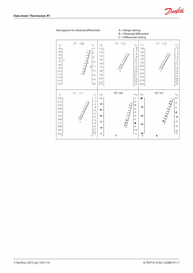
A = Range settingB = Obtained differential
C = Differential settingNomograms for obtained differentials
© Danfoss | DCS (az) | 2017.10
Data sheet | Thermostat, RT
IC.PD.P10.1E.02 | 520B8147 | 7
Nomograms for obtained differentials A = Range settingB = Obtained differentialC = Differential setting

© Danfoss | DCS (az) | 2017.10
p
p
t
t
Data sheet | Thermostat, RT
IC.PD.P10.1E.02 | 520B8147 | 8
Function a. RT thermostats with automatic reset
The RT thermostats are set according to the function required on falling temperature.
Contacts 1 – 4 break while contacts 1 – 2 make when the temperature falls to the scale setting. The contacts changeover to their initial position when the temperature again rises to the scale setting plus the differential (see fig. 9).
b. RT thermostats with max. reset
Contacts 1 – 4 make while contacts 1 – 2 break when the temperature exceeds the set range value.
The contacts changeover to their initial position when the temperature falls to the scale value minus the differential (see fig. 10).
Contact functionI. Contact changeover for rising temperature
occurs at scale setting plus differential.II. Contact changeover for falling temperatue
occurs at scale setting.
I. Alarm for rising temperature given at the set value.
II. Alarm for falling temperature given at the set value minus the differential.
Manual reset possible only when the temperature has fallen to the range setting minus differential.
RT units with vapour charge
The method of operation of these units is based on the connection between the pressure and temperature of satuated vapour. The sensor system contains just a small amount of liquid and this is brought completely to vapour form. If the sensor in this type of unit is located coldest in relation to the capillary tube and bellows housing, the ambient temperature has no influence on regulation accuracy.
Scale setting −−−
Differential
Fig. 9
Scale setting −−−
Differential
Fig. 10
Fig. 11
Satuated vapour
Gas
Pressure
Temperature

© Danfoss | DCS (az) | 2017.10
Data sheet | Thermostat, RT
IC.PD.P10.1E.02 | 520B8147 | 9
RT units with adsorption charge
The thermostatic element contains a superheated gas together with a solid substance (always in the sensor) having a large adsorption surface. This gives an advantage in that the sensor can be installed either colder or warmer than the remaining part of the thermostatic element. However, the charge is to some extent sensitive to changes in the temperature of the bellows and capillary tube.
Scale correction
If the thermostat is to be used in ambient tempratures that differ significantly from the factory setting (20 °C), compensation can be made for the scale deviation:
Scale correction = Z x a Z can be found from fig. 11c, while a is the correction factor from the table.
Example:
Find the necessary scale correction for a RT 108 with a regulation range 30 – 140 °C.
Setting: 85 °C
Ambient temperature: 50 °C
Correction:
Correction factor from table 2.0 (a) Factor for scale deviation (see fig. 11c): + 1.2 (Z)Scale correction: Z x a = 1.2 x 2.0 = 2.4 °C Corrected setting: 85 + 2.4 = 87.4
The method of operation of these units is based on the connection between the pressure and temperature of saturated vapour.
The sensor system contains a fairly large amount of liquid, of which only a small part is brought to vapour form. If the sensor in this type of unit is located warmest in relation to the capillary tube and bellows housing, the ambient temperature has no influence on regulation accuracy.
RT units with solid charge
Set value - min. scale valuemax. scale value - min. scale value
× 100 = %
85 - 30140 - 30
× 100 = 50%
TypeRange
[°C]Correction factor a
RT 2 -25 – 15 2.3
RT 7 -25 – 15 2.9
RT 8/L -20 – 12 1.7
RT 12 -5 – 10 1.2
RT 14/L -5 – 20 2.4
RT 15 8 – 32 1.2
RT 23 5 – 22 0.6
RT 101/L 25 – 90 5.0
RT 102 25 – 90 5.0
RT 108 30 – 140 2.0
RT 140/L 15 – 45 3.1
Factor for scale deviation
Rela
tive
scal
e se
ttin
g %
Fig. 11b
Fig. 11c
Fig. 11d

© Danfoss | DCS (az) | 2017.10
[°C]
Data sheet | Thermostat, RT
IC.PD.P10.1E.02 | 520B8147 | 10
017-519766, 380 V 017-519766, 239 V 017-519866, 230 V
The bulb sensor is heated by an element which is cut in when the thermostat stops the fans and is cut out when the thermostat starts the fans.
The for of operation is as follows:
If the room temperature is more than the value set on the thermostat, 20 °C for example, the fans run continuously (100% operating time). If the room temperature falls to 20 °C, the switch contacts changeover, the fan stops and the bulb sensor heating element cuts in.
When the bulb sensor is heated up, pressure in the sensor system increases and after a certain time the switch changes over again thereby cutting in the fans and cutting out the element.
If the room temperature falls more than 2 °C under the set temperature - in this example, lower than 18 °C - the fans stop completely. The heating element is cut in as usual but can no longer heat the bulb sensor sufficiently to create the required pressure increase in the thermostatic element to cut in the fans again. Thus with a room temperature of less than 18 °C the operating time is 0%.
An example is shown in fig. 13.
With temperature settings other than the one shown, the inclined line in the diagram is displaced parallel. The line break point on the right of the diagram always corresponds to the set value. It is therefore possible to maintain a stable room temperature and at the same time obtain periodic ventilation where the duration of the ventilation periods depends on the difference between the actual room temperature and the set temperature.
By ensuring that the thermostat is always set at least 2 °C over the lowest permissible room temperature, the thermostat will never allow the room temperature to fall below the desired level.
RT 115 for control of ventilation plant in livestock buildings
RT 115 has two sensors, each of which is connected to the space between bellows and bellows housing; see fig. 12. One sensor is a normal, external, rigid coiled capillary tube type, the other is a bulb sensor located in the thermostat housing.
A. Series resistorB. Bulb sensorC. Heating element
Ventilator running time in [%]
A: Phase input to fanB: Control lead
Connection diagrams for RT 115
Setting example
Fig. 12
Fig. 13

© Danfoss | DCS (az) | 2017.10
Data sheet | Thermostat, RT
IC.PD.P10.1E.02 | 520B8147 | 11
Application RT-L thermostats are fitted with an adjustable neutral zone. This enables the units to be used for floating control. The terminology involved is explained below.
Floating controlA form of discontinuous control where the correcting element (e.g. valve, damper, or similar) moves towards one extreme position at a rate independent of the magnitude of the error when the error exceeds a definite positive and towards the opposite extreme position when the error exceeds a definite negative value.
HuntingPeriodic variations of the controlled variable from the fixed reference.
Neutral zone setting The range is set using the setting knob (5), fig. 14, while reading the main scale (9). The set value is the break temperature for contacts 1-4, fig. 15. The required neutral zone can be found in the diagram for the unit concerned, fig. 16. The position at which the neuttral zone disc (40) must be set can be read from the low scale in the diagram.
Example: RT 16L
Setting temperature: 24 °C Required neutral zone: 1.9 °C
Using the setting knob, set the thermostat on 24 °C. The dotted lines in the diagram for the RT 16L fig. 16 intersect each other on the curve for position 2.8 and the neutral zone setting disc (40) must be set to that position.
Neutral zoneThe interval in the controlled variable in which the correcting element does not respond.
Mechanical differentialThe interval between the values of the controlled variable in which the correcting element does respond.
The contact system in neutral zone units cannot be exchanged, as the contact system adjustment is adjusted to the other parts of the unit.
5. Setting knob9. Main scale40. Neutral zone disc with scale
Fig. 14
Fig. 15
Fig. 16
Scalesetting
Temperature Dead zone
No. position
No. setting
© Danfoss | DCS (az) | 2017.10
[bar]
[°C]
Data sheet | Thermostat, RT
IC.PD.P10.1E.02 | 520B8147 | 12
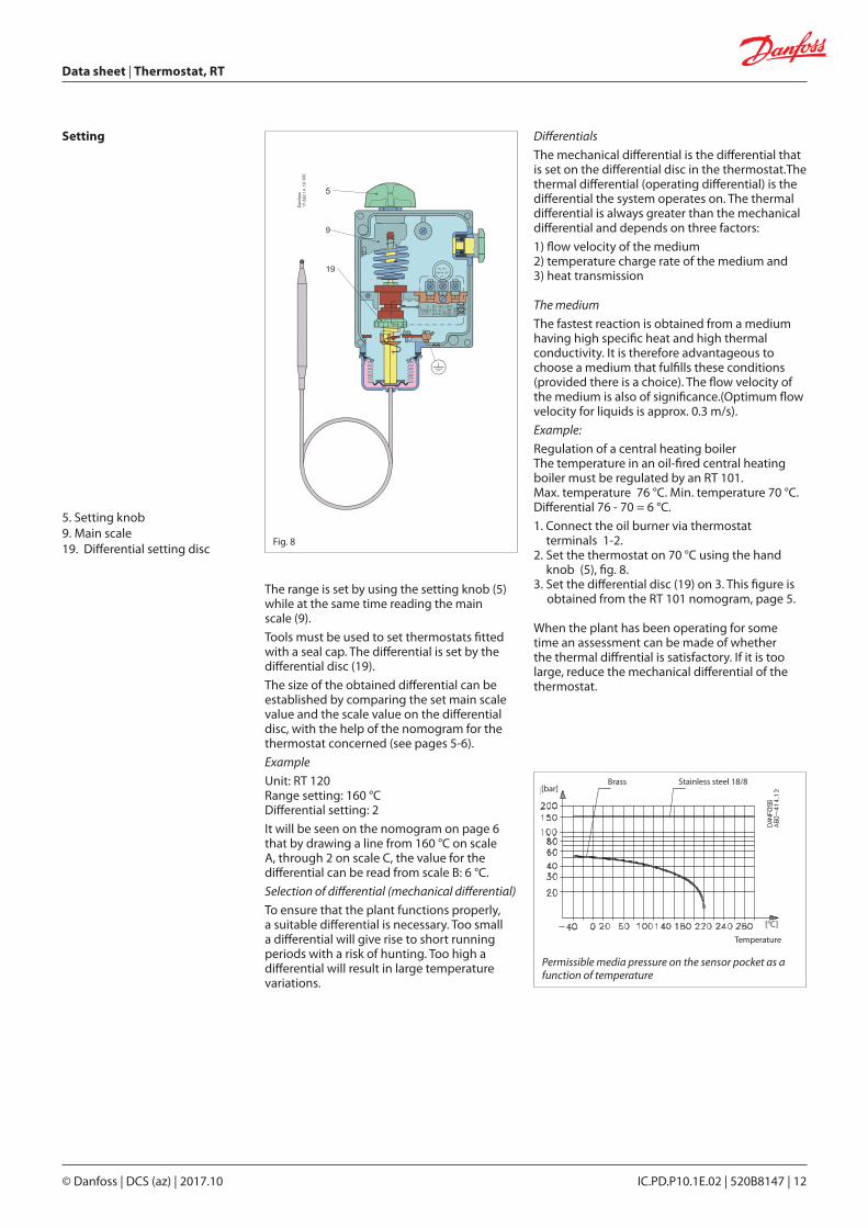
Differentials
The mechanical differential is the differential that is set on the differential disc in the thermostat.The thermal differential (operating differential) is the differential the system operates on. The thermal differential is always greater than the mechanical differential and depends on three factors:
1) flow velocity of the medium2) temperature charge rate of the medium and3) heat transmission
The medium
The fastest reaction is obtained from a medium having high specific heat and high thermal conductivity. It is therefore advantageous to choose a medium that fulfills these conditions (provided there is a choice). The flow velocity of the medium is also of significance.(Optimum flow velocity for liquids is approx. 0.3 m/s).
Example:
Regulation of a central heating boiler The temperature in an oil-fired central heating boiler must be regulated by an RT 101. Max. temperature 76 °C. Min. temperature 70 °C. Differential 76 - 70 = 6 °C.
1. Connect the oil burner via thermostat terminals 1-2.2. Set the thermostat on 70 °C using the hand knob (5), fig. 8.3. Set the differential disc (19) on 3. This figure is
obtained from the RT 101 nomogram, page 5.
When the plant has been operating for some time an assessment can be made of whether the thermal diffrential is satisfactory. If it is too large, reduce the mechanical differential of the thermostat.
The range is set by using the setting knob (5) while at the same time reading the main scale (9).
Tools must be used to set thermostats fitted with a seal cap. The differential is set by the differential disc (19).
The size of the obtained differential can be established by comparing the set main scale value and the scale value on the differential disc, with the help of the nomogram for the thermostat concerned (see pages 5-6).
Example
Unit: RT 120 Range setting: 160 °C Differential setting: 2
It will be seen on the nomogram on page 6 that by drawing a line from 160 °C on scale A, through 2 on scale C, the value for the differential can be read from scale B: 6 °C.
Selection of differential (mechanical differential)
To ensure that the plant functions properly, a suitable differential is necessary. Too small a differential will give rise to short running periods with a risk of hunting. Too high a differential will result in large temperature variations.
5. Setting knob9. Main scale19. Differential setting disc
Setting
Brass Stainless steel 18/8
Permissible media pressure on the sensor pocket as a function of temperature
Temperature
Fig. 8
© Danfoss | DCS (az) | 2017.10
RT 4RT 11RT 16, RT 16LRT 17RT 34RT 103RT 115
RT 2RT 3RT 9
RT 106RT 107RT 120RT 123
RT 7RT 8, RT 8LRT 10RT 12RT 13RT 14, RT 14LRT 15RT 21RT 23RT 24RT 26RT 101, RT 101LRT 108RT 124RT 140, RT 140L
RT 270RT 271
Data sheet | Thermostat, RT
IC.PD.P10.1E.02 | 520B8147 | 13
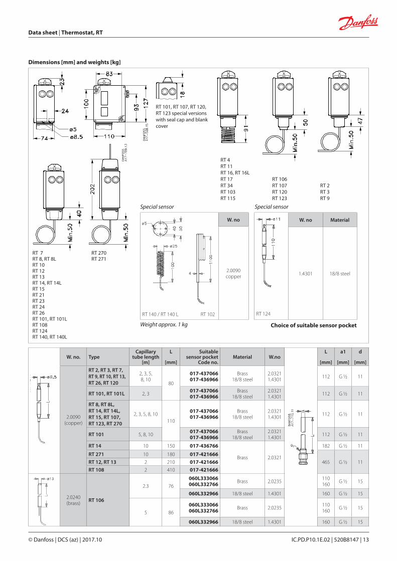
W. no. TypeCapillary
tube length[m]
L
[mm]
Suitable sensor pocket
Code no.Material W.no
L
[mm]
a1
[mm]
d
[mm]
2.0090(copper)
RT 2, RT 3, RT 7, RT 9, RT 10, RT 13, RT 26, RT 120
2, 3, 5,8, 10
80
017-437066017-436966
Brass18/8 steel
2.03211.4301 112 G ½ 11
RT 101, RT 101L 2, 3 017-437066017-436966
Brass18/8 steel
2.03211.4301 112 G ½ 11
RT 8, RT 8L, RT 14, RT 14L, RT 15, RT 107, RT 123, RT 270
2, 3, 5, 8, 10110
017-437066017-436966
Brass18/8 steel
2.03211.4301 112 G ½ 11
RT 101 5, 8, 10 017-437066017-436966
Brass18/8 steel
2.03211.4301 112 G ½ 11
RT 14 10 150 017-436766
Brass 2.0321
182 G ½ 11
RT 271 10 180 017-421666
465 G ½ 11RT 12, RT 13 2 210 017-421666
RT 108 2 410 017-421666
2.0240(brass) RT 106
2.3 76
060L333066060L332766 Brass 2.0235 110
160 G ½ 15
060L332966 18/8 steel 1.4301 160 G ½ 15
5 86
060L333066060L332766 Brass 2.0235 110
160 G ½ 15
060L332966 18/8 steel 1.4301 160 G ½ 15
Dimensions [mm] and weights [kg]
RT 101, RT 107, RT 120, RT 123 special versions with seal cap and blank cover
Special sensor Special sensor
RT 140 / RT 140 L RT 102
W. no
2.0090 copper
RT 124
W. no Material
1.4301 18/8 steel
Weight approx. 1 kg Choice of suitable sensor pocket

© Danfoss | DCS (az) | 2017.10
Data sheet | Thermostat, RT
IC.PD.P10.1E.02 | 520B8147 | 14
Version Symbol Description Contact rating Code no.
Standard
Single-pole changeover switch (SPDT) withterminal board proof against leakate current Fitted in all standard versions of type RT 1).Snap action changeover contacts.
Alternating current: AC-1 (ohmic): 10 A, 400 VAC-3 (inductive): 4 A, 400 VAC-15: 3 A, 400 VBlocked rotor: 28 A, 400 V Direct current: DC-13: 12 W, 220 V
017-403066
With max. reset
For manual reset of unit after contactchangeover on rising pressure.
For units with max. reset.
017-404266
With min. reset
For manual reset of units after contactchangeover on falling pressure.
For units with min. reset.017-404166
Standard
Single-pole changeover switch (SPDT) with gold plated (oxide-free) contact surfaces.Increases cut-in reliability on alarm and monitorin systems, etc.Snap action changeover contacts.Terminal board proof against leakage current.
Alternating current:AC-1(ohmic): 10 A, 400 VAC-3 (inductive): 2 A, 400 VAC-15: 1 A, 400 VBlocked rotor: 14 A, 400 V Direct current:DC-13: 12 W, 220 V
017-424066
Cuts in two circuits simultaneously
Single-pole changeover switch that cuts in two circuits simultaneously on rising pressure. Snap action changeover contacts.Terminal board proof against leakage current.
Alternating current:AC-1(ohmic): 10 A, 400 VAC-3 (inductive): 3 A, 400 VAC-15: 2 A, 400 VBlocked rotor: 21 A, 400 VDirect current:DC-13: 12 W, 220 V *)
*) If current is led through contacts 2 and 4, i.e. terminals 2 and 4 connected but not 1, max. permissible load is increased to 90 W, 220 V - - -.
017-403466
With non-snap action changeover contacts
Single-pole changeover with non-snap action changeover gold plated (oxide-free) contacts.
Alternating or direct current:25 VA, 24 V 017-018166
1) At load types with low currents/voltages contact failure may occure on the silver contacts because of oxidation. In systems where such a contact failure is of great importance (alarm etc.), gold plated contacts are recommended. Contact systems for neutral zone units are not available as spare parts. Exchange not possible, as the contact system adjustment is adjusted to the other parts of the unit.
Spare parts and accessories
The switch contacts are shown in the position they assume on falling temperature, i.e. after downward movement of the RT main spindle.
The setting pointer of the control shows the scale value at which contact changeover occurs on falling temperature. An exception is switch no. 017-403066 with max. reset where the setting pointer shows the scale value at which contact changeover occurs on rising pressure.
Switches
Version Symbol Description Contact rating Code no.
With min. resetFor manual reset of unit after contact changeover on falling pressure. Gold plated (oxide-free) contact surfaces.
For Alarm application Alternating current: AC-1 (ohmic): 10 A, 400 V AC-3 (inductive): 2 A, 400 V Full load current: 2 A, 400 V AC-15: 1 A, 400 V Blocked rotor: 14 A, 400 V Direct current DC-13: 12 W, 220 V For control application max. 100 mA / 30 V AC / DC min. 1 mA / 5 V AC / DC
017-404766
With max. resetFor manual reset of unit after contact changeover on rising pressure.Gold plated (oxide-free) contact surfaces.
017-404866
© Danfoss | DCS (az) | 2017.10
Data sheet | Thermostat, RT
IC.PD.P10.1E.02 | 520B8147 | 15
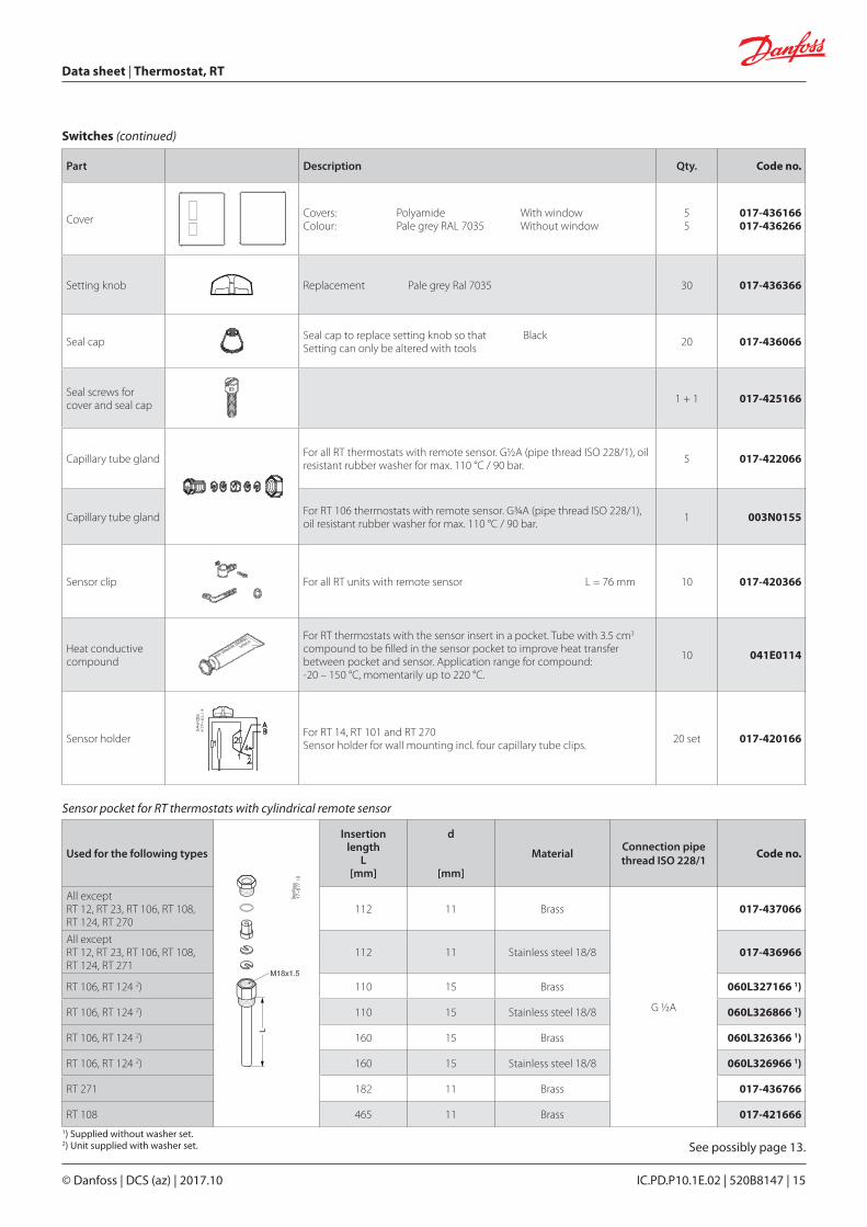
Sensor pocket for RT thermostats with cylindrical remote sensor
Used for the following types
Insertion length
L[mm]
d
[mm]
MaterialConnection pipe thread ISO 228/1
Code no.
All except RT 12, RT 23, RT 106, RT 108, RT 124, RT 270
112 11 Brass
G ½A
017-437066
All except RT 12, RT 23, RT 106, RT 108, RT 124, RT 271
112 11 Stainless steel 18/8 017-436966
RT 106, RT 124 2) 110 15 Brass 060L327166 1)
RT 106, RT 124 2) 110 15 Stainless steel 18/8 060L326866 1)
RT 106, RT 124 2) 160 15 Brass 060L326366 1)
RT 106, RT 124 2) 160 15 Stainless steel 18/8 060L326966 1)
RT 271 182 11 Brass 017-436766
RT 108 465 11 Brass 017-4216661) Supplied without washer set.2) Unit supplied with washer set.
Part Description Qty. Code no.
Cover Covers: Polyamide With windowColour: Pale grey RAL 7035 Without window
55
017-436166017-436266
Setting knob Replacement Pale grey Ral 7035 30 017-436366
Seal cap Seal cap to replace setting knob so that BlackSetting can only be altered with tools 20 017-436066
Seal screws for cover and seal cap 1 + 1 017-425166
Capillary tube gland For all RT thermostats with remote sensor. G½A (pipe thread ISO 228/1), oil resistant rubber washer for max. 110 °C / 90 bar. 5 017-422066
Capillary tube gland For RT 106 thermostats with remote sensor. G¾A (pipe thread ISO 228/1), oil resistant rubber washer for max. 110 °C / 90 bar. 1 003N0155
Sensor clip For all RT units with remote sensor L = 76 mm 10 017-420366
Heat conductive compound
For RT thermostats with the sensor insert in a pocket. Tube with 3.5 cm3 compound to be filled in the sensor pocket to improve heat transfer between pocket and sensor. Application range for compound: -20 – 150 °C, momentarily up to 220 °C.
10 041E0114
Sensor holder For RT 14, RT 101 and RT 270Sensor holder for wall mounting incl. four capillary tube clips. 20 set 017-420166
Switches (continued)
See possibly page 13.

© Danfoss | DCS (az) | 2017.10 IC.PD.P10.1E.02 | 520B8147 | 16
Installation RT units have two fixing holes which become accessible when the front cover is removed. Units fitted with switch 017-018166 *) must be installed with the setting knob upwards.
The other thermostats in the RT series can be installed in any position, except that on plant subjected to severe vibrations it is advantageous to have the screwed cable entry downwards.
*) Contact system with non snap-action function. See spare parts and accessories, page 14.
Fig. 7 Position of unit.