DATA SHEET SKY67150-396LF: 300 to 2200 MHz Ultra …€“13 –10 –11 –9 –8 Input Return Lo...
19
Skyworks Solutions, Inc. • Phone [781] 376-3000 • Fax [781] 376-3100 • [email protected] • www.skyworksinc.com 202922I • Skyworks Proprietary Information • Products and Product Information are Subject to Change Without Notice May 3, 2017 1 DATA SHEET SKY67150-396LF: 300 to 2200 MHz Ultra Low-Noise Amplifier Applications LTE, GSM, WCDMA, HSDPA macro and micro base stations UHF and L-band ultra low-noise receivers Cellular repeaters, DAS and RRH/RRUs High temperature transceiver applications to +105 °C Features Ultra-low Evaluation Board NF of 0.23 dB @ 849 MHz High OIP3 performance: +39 dBm Adjustable supply current from 20 to 100 mA Flexible bias voltage: 3 to 5 V Temperature and process-stable active bias Miniature DFN (8-pin, 2 x 2 mm) package (MSL1 @ 260 C per JEDEC J-STD-020) Skyworks Green TM products are compliant with all applicable legislation and are halogen-free. For additional information, refer to Skyworks Definition of Green TM , document number SQ04–0074. 4 3 2 1 5 6 7 8 N/C VBIAS RFIN N/C N/C ENABLE RFOUT/VDD N/C Y0004 Figure 2. SKY67150-396LF Pinout (Top View) RFIN VBIAS RFOUT/VDD ENABLE Active Bias 202922-001 Figure 1. SKY67150-396LF Block Diagram Description The SKY67150-396LF is GaAs, pHEMT low-noise amplifier (LNA) with an active bias, high linearity, superior gain, and industry- leading noise figure (NF) performance. The device features Skyworks advanced, pHEMT enhancement mode process in a compact 2 x 2 mm, 8-pin Dual Flat No-Lead (DFN) package. The internal active bias circuitry provides stable performance over temperature and process variation. The device offers the ability to externally adjust supply current. Supply voltage is applied to the RFOUT/VDD pin through an RF choke inductor. The RFIN and RFOUT/VDD pins should be DC blocked to ensure proper operation. The SKY67150-396LF operates in the frequency range of 300 to 2200 MHz using a common layout and band-specific tunes. Operation with high gain and a low NF at frequencies as low as 100 MHz is possible with degraded input return loss. A functional block diagram is shown in Figure 1. The pin configuration and package are shown in Figure 2. Signal pin assignments and functional pin descriptions are provided in Table 1.
-
Upload
nguyenminh -
Category
Documents
-
view
213 -
download
0
Transcript of DATA SHEET SKY67150-396LF: 300 to 2200 MHz Ultra …€“13 –10 –11 –9 –8 Input Return Lo...

Skyworks Solutions, Inc. • Phone [781] 376-3000 • Fax [781] 376-3100 • [email protected] • www.skyworksinc.com 202922I • Skyworks Proprietary Information • Products and Product Information are Subject to Change Without Notice May 3, 2017 1
DATA SHEET
SKY67150-396LF: 300 to 2200 MHz Ultra Low-Noise Amplifier Applications
LTE, GSM, WCDMA, HSDPA macro and micro base stations
UHF and L-band ultra low-noise receivers
Cellular repeaters, DAS and RRH/RRUs
High temperature transceiver applications to +105 °C
Features
Ultra-low Evaluation Board NF of 0.23 dB @ 849 MHz
High OIP3 performance: +39 dBm
Adjustable supply current from 20 to 100 mA
Flexible bias voltage: 3 to 5 V
Temperature and process-stable active bias
Miniature DFN (8-pin, 2 x 2 mm) package (MSL1 @ 260 C per JEDEC J-STD-020)
Skyworks GreenTM products are compliant withall applicable legislation and are halogen-free.For additional information, refer to SkyworksDefinition of GreenTM, document number SQ04–0074.
4
3
2
1
5
6
7
8
N/C
VBIAS
RFIN
N/C
N/C
ENABLE
RFOUT/VDD
N/C
Y0004
Figure 2. SKY67150-396LF Pinout (Top View)
RFIN
VBIAS
RFOUT/VDD
ENABLE
ActiveBias
202922-001
Figure 1. SKY67150-396LF Block Diagram
Description The SKY67150-396LF is GaAs, pHEMT low-noise amplifier (LNA) with an active bias, high linearity, superior gain, and industry-leading noise figure (NF) performance. The device features Skyworks advanced, pHEMT enhancement mode process in a compact 2 x 2 mm, 8-pin Dual Flat No-Lead (DFN) package.
The internal active bias circuitry provides stable performance over temperature and process variation. The device offers the ability to externally adjust supply current. Supply voltage is applied to the RFOUT/VDD pin through an RF choke inductor. The RFIN and RFOUT/VDD pins should be DC blocked to ensure proper operation.
The SKY67150-396LF operates in the frequency range of 300 to 2200 MHz using a common layout and band-specific tunes. Operation with high gain and a low NF at frequencies as low as 100 MHz is possible with degraded input return loss.
A functional block diagram is shown in Figure 1. The pin configuration and package are shown in Figure 2. Signal pin assignments and functional pin descriptions are provided in Table 1.

DATA SHEET • SKY67150-396LF: ULTRA LOW-NOISE AMPLIFIER
Skyworks Solutions, Inc. • Phone [781] 376-3000 • Fax [781] 376-3100 • [email protected] • www.skyworksinc.com 2 May 3, 2017 • Skyworks Proprietary Information • Products and Product Information are Subject to Change Without Notice • 202922I
Table 1. SKY67150-396LF Signal Descriptions
Pin Name Description Pin Name Description
1 N/C No connection. May be connected to ground with no change in performance.
5 N/C No connection. May be connected to ground with no change in performance.
2 RFIN RF input. DC blocking capacitor required. 6 ENABLE Enable pin. Active low = amplifier “on” state
3 VBIAS Bias voltage for input gate. External resistor sets current consumption.
7 RFOUT/VDD RF output. Apply VDD through RF choke inductor. DC blocking capacitor required.
4 N/C No connection. May be connected to ground with no change in performance.
8 N/C No connection. May be connected to ground with no change in performance.
Electrical and Mechanical Specifications The absolute maximum ratings of the SKY67150-396LF are provided in Table 2. Electrical specifications are provided in Tables 3 through 7.
Typical performance characteristics are illustrated in Figures 3 through 21.
Table 2. SKY67150-396LF Absolute Maximum Ratings1
Parameter Symbol Minimum Maximum Units
Supply voltage VDD 5.5 V
Quiescent supply current IDQ 120 mA
RF input power PIN +21 dBm
Storage temperature TSTG –40 +150 C
Operating temperature TA –40 +105 C
Junction temperature TJ +150 C
Electrostatic discharge: Charged Device Model (CDM), Class 4 Human Body Model (HBM), Class 1A Machine Model (MM), Class A
ESD 1000 250 30
V V V
1 Exposure to maximum rating conditions for extended periods may reduce device reliability. There is no damage to device with only one parameter set at the limit and all other parameters set at or below their nominal value. Exceeding any of the limits listed here may result in permanent damage to the device.
ESD HANDLING: Although this device is designed to be as robust as possible, electrostatic discharge (ESD) can damage this device. This device must be protected at all times from ESD when handling or transporting. Static charges may easily produce potentials of several kilovolts on the human body or equipment, which can discharge without detection. Industry-standard ESD handling precautions should be used at all times.
Table 3. SKY67150-396LF Electrical Specifications: Thermal Data1 (VDD = 5 V, TA = +25 C, PIN = –25 dBm, Characteristic Impedance [ZO] = 50 Ω, Unless Otherwise Noted)
Parameter Symbol Test Condition Min Typical Max Units
Thermal resistance ΘJC 45 °C/W
Channel temperature @ +85 °C reference (package heat slug)
VDD = 5 V, IDQ = 82 mA, no RF applied, dissipated power = 0.35 W
103
°C 1 Performance is guaranteed only under the conditions listed in this table.

DATA SHEET • SKY67150-396LF: ULTRA LOW-NOISE AMPLIFIER
Skyworks Solutions, Inc. • Phone [781] 376-3000 • Fax [781] 376-3100 • [email protected] • www.skyworksinc.com 202922I • Skyworks Proprietary Information • Products and Product Information are Subject to Change Without Notice • May 3, 2017 3
Table 4. SKY67150-396LF Electrical Specifications: 650 to 1100 MHz Optimized Tuning1 (VDD = 5 V, TA = +25 C, PIN = –20 dBm, Characteristic Impedance [ZO] = 50 Ω, Unless Otherwise Noted)
Parameter Symbol Test Condition Min Typical Max Units
RF Specifications
Noise figure NF @ 849 MHz, includes Evaluation Board loss
0.23 0.38 dB
Small signal gain |S21| @ 849 MHz 19.0 20.5 dB
Input return loss |S11| @ 849 MHz 11 dB
Output return loss |S22| @ 849 MHz 20 dB
Reverse isolation |S12| @ 849 MHz 28 dB
Third order input intercept point IIP3 @ 849 MHz, Δf = 1 MHz, PIN = –20 dBm/tone
+15.5
+18.5
dBm
Third order output intercept point OIP3 @ 849 MHz, Δf = 1 MHz, PIN = –20 dBm/tone
+36
+39
dBm
1 dB input compression point IP1dB @ 849 MHz –0.5 +1.5 dBm
1 dB output compression point OP1dB @ 849 MHz +19 +21 dBm
DC Specifications
Supply voltage VDD 5 V
Quiescent supply current IDQ Set with external resistor 70 82 95 mA
Bias current IBIAS 500 μA
Enable voltage: Gain mode Power-down mode
VENABLE 0
1.5
0.2 5.5
V V
Enable rise time2 TR @ 849 MHz 250 500 ns
Enable fall time2 TF @ 849 MHz 250 500 ns 1 Performance is guaranteed only under the conditions listed in this table. 2 Tested with a 100 kHz square wave, 1000 pF capacitance-to-ground on the ENABLE pin. Switching time can be improved by reducing the value of, or eliminating, the 1000 pF capacitor on
pin 6 (component M17 in Figure 24).

DATA SHEET • SKY67150-396LF: ULTRA LOW-NOISE AMPLIFIER
Skyworks Solutions, Inc. • Phone [781] 376-3000 • Fax [781] 376-3100 • [email protected] • www.skyworksinc.com 4 May 3, 2017 • Skyworks Proprietary Information • Products and Product Information are Subject to Change Without Notice • 202922I
Typical Performance Characteristics, 650 to 1100 MHz (VDD = 5 V, TA = +25 C, PIN = –20 dBm, Characteristic Impedance [Zo] = 50 Ω, Unless Otherwise Noted)
0.1
0
0.3
0.2
0.5
0.4
0.6
0.7
700 750600 650 800 850 950900 1000 1050 1100 1150 1200
Frequency (MHz)
Nois
e Fi
gure
(dB)
–40 °C+25 °C+85 °C+105 °C
2029
22-0
03
Figure 3. Evaluation Board NF vs Frequency over Temperature
–30
–40
–50
–60
–70
–80
–10
–20
+10
0
+20
+30
4 60 2 8 10 1412 16 18 20 22 24
Frequency (GHz)
Smal
l Sig
nal G
ain
(dB)
–40 °C+25 °C+85 °C+105 °C
2029
22-0
05
Figure 5. Broadband Gain vs Frequency over Temperature
–10
–12
–14
–16
–18
–6
–8
–2
–4
0
+2
Inpu
t Ret
urn
Loss
(dB)
4 60 2 8 10 1412 16 18 20 22 24
Frequency (GHz)
–40 °C+25 °C+85 °C+105 °C
2029
22-0
07
Figure 7. Broadband Input Return Loss vs Frequency over Temperature
19
18
17
16
15
21
20
23
22
24
25
700 750600 650 800 850 950900 1000 1050 1100 1150 1200
Frequency (MHz)
Smal
l Sig
nal G
ain
(dB)
–40 °C+25 °C+85 °C+105 °C
2029
22-0
04
Figure 4. Narrow Band Gain vs Frequency over Temperature
–14
–15
–16
–17
–18
–19
–20
–12
–13
–10
–11
–9
–8
Inpu
t Ret
urn
Loss
(dB)
700 750600 650 800 850 950900 1000 1050 1100 1150 1200
Frequency (MHz)
–40 °C+25 °C+85 °C+105 °C
2029
22-0
06
Figure 6. Narrowband Input Return Loss vs Frequency over Temperature
–30.0
–30.5
–31.0
–31.5
–32.0
–29.0
–29.5
–28.0
–28.5
–27.5
–27.0
Reve
rse
Isol
atio
n (d
B)
700 750600 650 800 850 950900 1000 1050 1100 1150 1200
Frequency (MHz)
–40 °C+25 °C+85 °C+105 °C
2029
22-0
08
Figure 8. Narrowband Reverse Isolation vs Frequency over Temperature

DATA SHEET • SKY67150-396LF: ULTRA LOW-NOISE AMPLIFIER
Skyworks Solutions, Inc. • Phone [781] 376-3000 • Fax [781] 376-3100 • [email protected] • www.skyworksinc.com 202922I • Skyworks Proprietary Information • Products and Product Information are Subject to Change Without Notice • May 3, 2017 5
–60
–70
–80
–40
–50
–20
–30
–10
0
Reve
rse
Isol
atio
n (d
B)
4 60 2 8 10 1412 16 18 20 22 24
Frequency (GHz)
–40 °C+25 °C+85 °C+105 °C
2029
22-0
09
Figure 9. Broadband Reverse Isolation vs Frequency over Temperature
–10
–12
–14
–16
–18
–6
–8
–2
–4
0
+2
Outp
ut R
etur
n Lo
ss (d
B)
4 60 2 8 10 1412 16 18 20 22 24
Frequency (GHz)
–40 °C+25 °C+85 °C+105 °C
2029
22-0
11
Figure 11. Broadband Output Return Loss vs Frequency over Temperature
0
2
1
4
3
5
6
Stab
ility
Fac
tor (
μ2)
4 60 2 8 10 1412 16 18 20 22 24
Frequency (GHz)
–40 °C+25 °C+85 °C+105 °C
2029
22-0
13
Figure 13. Stability Factor (μ2) vs Frequency over Temperature
–35
–25
–30
–15
–20
–10
–5
Outp
ut R
etur
n Lo
ss (d
B)
700 750600 650 800 850 950900 1000 1050 1100 1150 1200
Frequency (MHz)
–40 °C+25 °C+85 °C+105 °C
2029
22-0
10
Figure 10. Narrowband Output Return Loss vs Frequency over Temperature
0
2
1
4
3
5
6
Stab
ility
Fac
tor (
μ1)
4 60 2 8 10 1412 16 18 20 22 24
Frequency (GHz)
–40 °C+25 °C+85 °C+105 °C
2029
22-0
12
Figure 12. Stability Factor (μ1) vs Frequency over Temperature
0.20
0.30
0.25
0.40
0.35
0
0.10
0.05
0.15
0.45
0.50
Nois
e Fi
gure
(dB)
40 5020 30 60 70 9080 100
Quiescent Current (mA)
2029
22-0
14
Figure 14. Evaluation Board NF vs Quiescent Current over Frequency Using Band-Specific BOM (@ 849 MHz)

DATA SHEET • SKY67150-396LF: ULTRA LOW-NOISE AMPLIFIER
Skyworks Solutions, Inc. • Phone [781] 376-3000 • Fax [781] 376-3100 • [email protected] • www.skyworksinc.com 6 May 3, 2017 • Skyworks Proprietary Information • Products and Product Information are Subject to Change Without Notice • 202922I
20
25
30
35
40
45
–20 –18 –16 –14 –12 –10 –8 –6 –4
OIP
3 (
dBm
)
Input Power Over Temperature (dBm)
–40 °C
+25 °C
+85 °C
+105 °C
20
29
22
-01
5
Figure 15. OIP3 vs Input Power Over Temperature (@849 MHz, 1MHz Spacing)
+20
+30
+25
+35
0
+10
+5
+15
+40
+45
OIP3
(dBm
)
40 5020 30 60 70 9080 100
Quiescent Current (mA)
2029
22-0
16
Figure 16. OIP3 vs Quiescent Current over Frequency Using Band-Specific BOM (@ 849 MHz)
Table 5. SKY67150-396LF Electrical Specifications: 380 to 530 MHz Optimized Tuning1 (VDD = 5 V, TA = +25 C, PIN = –25 dBm, Characteristic Impedance [ZO] = 50 Ω, Unless Otherwise Noted)
Parameter Symbol Test Condition Min Typical Max Units
RF Specifications
Noise figure NF @ 450 MHz, includes Evaluation Board loss
0.45 0.60 dB
Small signal gain |S21| @ 450 MHz 21.5 23.0 dB
Input return loss |S11| @ 450 MHz 12 dB
Output return loss |S22| @ 450 MHz 20 dB
Reverse isolation |S12| @ 450 MHz 33 dB
Third order input intercept point IIP3 @ 450 MHz, Δf = 1 MHz, PIN = –25 dBm/tone
+10
+13
dBm
Third order output intercept point OIP3 @ 450 MHz, Δf = 1 MHz, PIN = –25 dBm/tone
+33
+36
dBm
1 dB input compression point IP1dB @ 450 MHz –5 –3 dBm
1 dB output compression point OP1dB @ 450 MHz +17 +19 dBm
DC Specifications
Supply voltage VDD 5 V
Quiescent supply current IDQ Set with external resistor 82 mA
Bias current IBIAS 500 μA
Enable rise time2 TR @ 450 MHz 250 500 ns
Enable fall time2 TF @ 450 MHz 250 500 ns 1 Performance is guaranteed only under the conditions listed in this table. 2 Tested with a 100 kHz square wave, 1000 pF capacitance-to-ground on the ENABLE pin. Switching time can be improved by reducing the value of, or eliminating, the 1000 pF capacitor on
pin 6 (component M17 in Figure 24).

DATA SHEET • SKY67150-396LF: ULTRA LOW-NOISE AMPLIFIER
Skyworks Solutions, Inc. • Phone [781] 376-3000 • Fax [781] 376-3100 • [email protected] • www.skyworksinc.com 202922I • Skyworks Proprietary Information • Products and Product Information are Subject to Change Without Notice • May 3, 2017 7
Table 6. SKY67150-396LF Electrical Specifications: 1400 to 2200 MHz Optimized Tuning1 (VDD = 5 V, TA = +25 C, PIN = –25 dBm, Characteristic Impedance [ZO] = 50 Ω, Unless Otherwise Noted)
Parameter Symbol Test Condition Min Typical Max Units
RF Specifications
Noise figure NF @ 1900 MHz, includes Evaluation Board loss
0.38 0.53 dB
Small signal gain |S21| @ 1900 MHz 13.0 14.5 dB
Input return loss |S11| @ 1900 MHz 17 dB
Output return loss |S22| @ 1900 MHz 20 dB
Reverse isolation |S12| @ 1900 MHz 23 dB
Third order input intercept point IIP3 @ 1900 MHz, Δf = 1 MHz, PIN = –25 dBm/tone
+19
+22
dBm
Third order output intercept point OIP3 @ 1900 MHz, Δf = 1 MHz, PIN = –25 dBm/tone
+33.5
+36.5
dBm
1 dB input compression point IP1dB @ 1900 MHz +2.5 +4.5 dBm
1 dB output compression point OP1dB @ 1900 MHz +16 +18 dBm
DC Specifications
Supply voltage VDD 5 V
Quiescent supply current IDQ Set with external resistor 82 mA
Bias current IBIAS 500 μA
Enable rise time2 TR @ 1900 MHz 250 500 ns
Enable fall time2 TF @ 1900 MHz 250 500 ns 1 Performance is guaranteed only under the conditions listed in this table. 2 Tested with a 100 kHz square wave, 1000 pF capacitance-to-ground on the ENABLE pin. Switching time can be improved by reducing the value of, or eliminating, the 1000 pF capacitor on
pin 6 (component M17 in Figure 24).
0
–5
–10
–15–20
–25–30
–35
–55
–40
+10
+5
+20
+15
+25
+30
Retu
rn L
oss
& Sm
all S
igna
l Gai
n (d
B)
0.50
0.25
0
1.00
0.75
1.50
1.25
1.75
2.00
Nois
e Fi
gure
(dB)
400 450300 350 500 550 600
Frequency (MHz)
S11GainS22NF
202922-017
Figure 17. Evaluation Board NF, Gain, and Return Losses for 380 to 530 MHz Tuning
Retu
rn L
oss
& Sm
all S
igna
l Gai
n (d
B)
Nois
e Fi
gure
(dB)
Frequency (GHz)
0.00
0.25
0.50
0.75
1.00
1.25
1.50
1.75
2.00
–45
–40
–35
–30
–25
–20
–15
–10
–5
0
+5
+10
+15
+20
+25
+30
1.3 1.4 1.5 1.6 1.7 1.8 1.9 2.0 2.1 2.2 2.3
S11GainS22NF
202922-018
Figure 18. Evaluation Board NF, Gain, and Return Losses for 1400 to 2200 MHz Tuning

DATA SHEET • SKY67150-396LF: ULTRA LOW-NOISE AMPLIFIER
Skyworks Solutions, Inc. • Phone [781] 376-3000 • Fax [781] 376-3100 • [email protected] • www.skyworksinc.com 8 May 3, 2017 • Skyworks Proprietary Information • Products and Product Information are Subject to Change Without Notice • 202922I
Table 7. Noise Parameters vs Frequency (@ +25 °C, 5 V, 70 mA)
Frequency (GHz)
FMIN (dB)
Gamma opt (Mag)
Gamma opt (Phase)
Noise Resistance (RN) (Ω)
Associated Gain (dB)
Maximum Gain (GMAX) (dB)
0.4 0.3356 0.3898 –1.65 0.063 26.874 26.7297
0.45 0.3187 0.3471 2.44 0.0318 26.112 26.0677
0.5 0.3287 0.1473 –60.08 0.0484 25.6849 25.666
0.55 0.303 0.3392 6.77 0.0432 24.8282 24.8229
0.6 0.2702 0.2931 7.19 0.0347 24.2668 24.2489
0.65 0.2682 0.3336 19.52 0.0416 23.7339 23.7001
0.7 0.2735 0.3735 15.75 0.0508 23.2435 23.2303
0.75 0.2517 0.3303 18.12 0.0434 22.7786 22.7593
0.8 0.1996 0.2104 40.79 0.0494 22.3308 22.1323
0.85 0.1908 0.334 16.5 0.0628 21.9055 21.8755
0.9 0.1925 0.373 21 0.0341 21.501 21.4886
0.95 0.1946 0.3857 39.09 0.0271 21.1104 21.0495
1.1 0.2164 0.3831 34.68 0.0574 20.0289 20.0043
1.2 0.2327 0.3597 40.72 0.0665 19.3803 19.3273
1.3 0.2482 0.3419 41.76 0.049 18.7816 18.703
1.4 0.2798 0.3207 48.16 0.0573 18.2235 18.1058
1.5 0.3092 0.2854 59.17 0.0532 17.7114 17.5101
1.6 0.3287 0.312 75.86 0.0976 17.2272 16.9687
1.8 0.3516 0.4428 68.41 0.1833 16.34 16.2997
2.1 0.4897 0.4233 71.86 0.1996 15.1948 15.1438
2.3 0.5014 0.2079 70.76 0.0591 14.5509 14.0753

DATA SHEET • SKY67150-396LF: ULTRA LOW-NOISE AMPLIFIER
Skyworks Solutions, Inc. • Phone [781] 376-3000 • Fax [781] 376-3100 • [email protected] • www.skyworksinc.com 202922I • Skyworks Proprietary Information • Products and Product Information are Subject to Change Without Notice • May 3, 2017 9
Load
202922-019
Swept F1 Load Gamma PullFreq = 0.4500 GHzΓSource: 0.4332< 27.58
Ip3 max = 39.29 dBm at 0.5981< 99.88 5 contours, 0.50 dBm step(37.00 to 39.00 dBm)Gt max = 27.13 dB at 0.1978< 94.24 5 contours, 0.50 dB step(25.00 to 27.00 dB)Specs: OFF
Figure 19. OIP3 Load Pull @ 450 MHz, 5 V, 70 mA (Input Load = Min NF, –20 dBm/tone, 5 MHz Spacing)

DATA SHEET • SKY67150-396LF: ULTRA LOW-NOISE AMPLIFIER
Skyworks Solutions, Inc. • Phone [781] 376-3000 • Fax [781] 376-3100 • [email protected] • www.skyworksinc.com 10 May 3, 2017 • Skyworks Proprietary Information • Products and Product Information are Subject to Change Without Notice • 202922I
Swept F1 Load Gamma PullFreq = 0.9000 GHzΓSource: 0.3655< 16.76
Ip3 max = 37.05 dBm at 0.3107< 170.63 5 contours, 0.50 dBm step(35.00 to 37.00 dBm)Gt max = 21.90 dB at 0.3914< 162.55 5 contours, 0.50 dB step(19.50 to 21.50 dB)Specs: OFF
Load
202922-020
Figure 20. OIP3 Load Pull @ 900 MHz, 5 V, 70 mA (Input Load = Min NF, –20 dBm/tone, 5 MHz Spacing)
DATA SHEET • SKY67150-396LF: ULTRA LOW-NOISE AMPLIFIER
Skyworks Solutions, Inc. • Phone [781] 376-3000 • Fax [781] 376-3100 • [email protected] • www.skyworksinc.com 202922I • Skyworks Proprietary Information • Products and Product Information are Subject to Change Without Notice • May 3, 2017 11
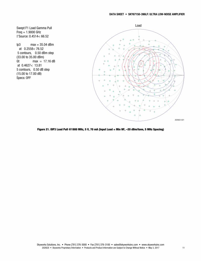
Swept F1 Load Gamma PullFreq = 1.9000 GHzΓSource: 0.4514< 66.52
Ip3 max = 35.04 dBm at 0.2558< 76.52 5 contours, 0.50 dBm step(33.00 to 35.00 dBm)Gt max = 17.16 dB at 0.4627< 13.81 5 contours, 0.50 dB step(15.00 to 17.00 dB)Specs: OFF
Load
202922-021
Figure 21. OIP3 Load Pull @1900 MHz, 5 V, 70 mA (Input Load = Min NF, –20 dBm/tone, 5 MHz Spacing)

DATA SHEET • SKY67150-396LF: ULTRA LOW-NOISE AMPLIFIER
Skyworks Solutions, Inc. • Phone [781] 376-3000 • Fax [781] 376-3100 • [email protected] • www.skyworksinc.com 12 May 3, 2017 • Skyworks Proprietary Information • Products and Product Information are Subject to Change Without Notice • 202922I
Evaluation Board Description The SKY67150-396LF Evaluation Board is used to test the performance of the SKY67150-396LF LNA. Three different boards are available for different frequency operations: 380 to 530 MHz, 650 to 1100 MHz, and 1400 to 2200 MHz.
An assembly drawing for the Evaluation Board is shown in Figure 22. The layer detail is provided in Figure 23. An Evaluation Board schematic diagram is provided in Figure 24. Tables 8, 9, and 10 provide the Bill of Materials (BOM) list for the three different Evaluation Board tuning frequencies.
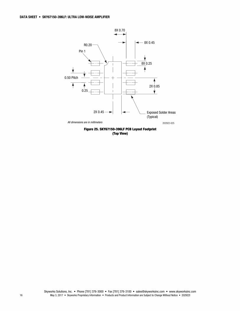
Package Dimensions The PCB layout footprint for the SKY67150-396LF is provided in Figure 25. Typical part markings are shown in Figure 26. Package dimensions are shown in Figure 27, and tape and reel dimensions are provided in Figure 28.
Package and Handling Information Instructions on the shipping container label regarding exposure to moisture after the container seal is broken must be followed. Otherwise, problems related to moisture absorption may occur when the part is subjected to high temperature during solder assembly.
The SKY67150-396LF is rated to Moisture Sensitivity Level 1 (MSL1) at 260 C. It can be used for lead or lead-free soldering. For additional information, refer to the Skyworks Application Note, Solder Reflow Information, document number 200164.
Care must be taken when attaching this product, whether it is done manually or in a production solder reflow environment. Production quantities of this product are shipped in a standard tape and reel format.

DATA SHEET • SKY67150-396LF: ULTRA LOW-NOISE AMPLIFIER
Skyworks Solutions, Inc. • Phone [781] 376-3000 • Fax [781] 376-3100 • [email protected] • www.skyworksinc.com 202922I • Skyworks Proprietary Information • Products and Product Information are Subject to Change Without Notice • May 3, 2017 13
202922-022
Figure 22. SKY67150-396LF Evaluation Board Assembly Diagram
202922-023
Cross Section Name Thickness (mm) Material
MSK-NS
TRA-NS 0.03556 Cu foil
Laminate 0.254 ± 0.152 Rogers 4350B
TRA-2 0.0178 Cu foil
Laminate 0.889 nom. FR4 Prepreg (Note 1)
TRA-3 0.0178 Cu foil
Laminate 0.254 ± 0.152 FR4 Core
TRA-FS 0.0178 Cu foil
MSK-PS
Note 1: Adjust this thickness to meet total thickness goal.
General Notes: Material: Rogers R04350, εr = 3.66 Layer 1 thickness: 0.254 mm Overall board thickness: 1.575 mm 50 Ω transmission line width: 0.522 mm Coplanar ground spacing: 0.394 mm Via diameter: 0.254 mm
Figure 23. Layer Detail Physical Characteristics

DATA SHEET • SKY67150-396LF: ULTRA LOW-NOISE AMPLIFIER
Skyworks Solutions, Inc. • Phone [781] 376-3000 • Fax [781] 376-3100 • [email protected] • www.skyworksinc.com 14 May 3, 2017 • Skyworks Proprietary Information • Products and Product Information are Subject to Change Without Notice • 202922I
4
3
2
1
5
6
7
8
N/C
VBIAS
RFIN
N/C
N/C
ENABLE
Enable
RFOUT/VDD
6-Pin Header
N/C
ENAB
LE
GND
GND
VBIA
S
GND
VDD
202922-024
×
××
×
M3 M12M10 M11
M16M8
M9
M2M4
M6
M5
M1RF Input RF Output
VDDVBIAS
M13
M17
M14
M15
M7
+ –
+ –
+ –
Figure 24. SKY67150-396LF Evaluation Board Schematic
Table 8. SKY67150-396LF Evaluation Board Bill of Materials (650 to 1100 MHz Tuning)
Component Description Value Size Manufacturer Part Number
M1 Inductor 8.2 nH 0603 Coilcraft HP 0603HP-8N2X_L
M2, M7 DNP
M3 Capacitor 20 pF 0402 Murata GJM GJM1555C1H200JB01
M4 Inductor 100 nH 0402 Coilcraft HP 0402HPH-R10X_L
M5, M17 Capacitor 1000 pF 0402 Murata GRM GRM1555C1H102JZ01
M6 Resistor 9.1 kΩ 0402 Kamaya RMC, 1/16S 1% RMC1/16S-9101FTH
M8 Capacitor 10000 pF 0402 Murata GRM GRM155R71H103KA88
M9, M12 Capacitor 10 pF 0402 Murata GRM GRM1555C1H100JZ01
M10 Inductor 10 nH 0402 Murata LQG LQG15HS10NJ02
M11 Resistor 562 Ω 0402 Kamaya RMC, 1/16S 1% RMC1/16SK5620FTH
M13 Capacitor 2.2 pF 0402 Murata GRM GRM1555C1H2R2CZ01
M14, M16 Resistor 0 Ω 0402 Kamaya RMC, 1/16S RMC1/16SJPTH
M15 Resistor 1 kΩ 0402 Kamaya RMC, 1/16S 1% RMC1/16SK1001FTH
DATA SHEET • SKY67150-396LF: ULTRA LOW-NOISE AMPLIFIER
Skyworks Solutions, Inc. • Phone [781] 376-3000 • Fax [781] 376-3100 • [email protected] • www.skyworksinc.com 202922I • Skyworks Proprietary Information • Products and Product Information are Subject to Change Without Notice • May 3, 2017 15
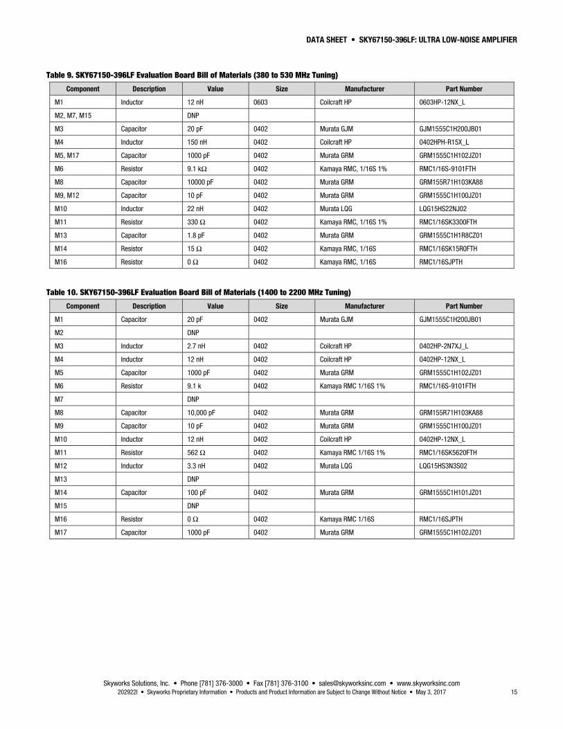
Table 9. SKY67150-396LF Evaluation Board Bill of Materials (380 to 530 MHz Tuning)
Component Description Value Size Manufacturer Part Number
M1 Inductor 12 nH 0603 Coilcraft HP 0603HP-12NX_L
M2, M7, M15 DNP
M3 Capacitor 20 pF 0402 Murata GJM GJM1555C1H200JB01
M4 Inductor 150 nH 0402 Coilcraft HP 0402HPH-R15X_L
M5, M17 Capacitor 1000 pF 0402 Murata GRM GRM1555C1H102JZ01
M6 Resistor 9.1 kΩ 0402 Kamaya RMC, 1/16S 1% RMC1/16S-9101FTH
M8 Capacitor 10000 pF 0402 Murata GRM GRM155R71H103KA88
M9, M12 Capacitor 10 pF 0402 Murata GRM GRM1555C1H100JZ01
M10 Inductor 22 nH 0402 Murata LQG LQG15HS22NJ02
M11 Resistor 330 Ω 0402 Kamaya RMC, 1/16S 1% RMC1/16SK3300FTH
M13 Capacitor 1.8 pF 0402 Murata GRM GRM1555C1H1R8CZ01
M14 Resistor 15 Ω 0402 Kamaya RMC, 1/16S RMC1/16SK15R0FTH
M16 Resistor 0 Ω 0402 Kamaya RMC, 1/16S RMC1/16SJPTH
Table 10. SKY67150-396LF Evaluation Board Bill of Materials (1400 to 2200 MHz Tuning)
Component Description Value Size Manufacturer Part Number
M1 Capacitor 20 pF 0402 Murata GJM GJM1555C1H200JB01
M2 DNP
M3 Inductor 2.7 nH 0402 Coilcraft HP 0402HP-2N7XJ_L
M4 Inductor 12 nH 0402 Coilcraft HP 0402HP-12NX_L
M5 Capacitor 1000 pF 0402 Murata GRM GRM1555C1H102JZ01
M6 Resistor 9.1 k 0402 Kamaya RMC 1/16S 1% RMC1/16S-9101FTH
M7 DNP
M8 Capacitor 10,000 pF 0402 Murata GRM GRM155R71H103KA88
M9 Capacitor 10 pF 0402 Murata GRM GRM1555C1H100JZ01
M10 Inductor 12 nH 0402 Coilcraft HP 0402HP-12NX_L
M11 Resistor 562 Ω 0402 Kamaya RMC 1/16S 1% RMC1/16SK5620FTH
M12 Inductor 3.3 nH 0402 Murata LQG LQG15HS3N3S02
M13 DNP
M14 Capacitor 100 pF 0402 Murata GRM GRM1555C1H101JZ01
M15 DNP
M16 Resistor 0 Ω 0402 Kamaya RMC 1/16S RMC1/16SJPTH
M17 Capacitor 1000 pF 0402 Murata GRM GRM1555C1H102JZ01
DATA SHEET • SKY67150-396LF: ULTRA LOW-NOISE AMPLIFIER
Skyworks Solutions, Inc. • Phone [781] 376-3000 • Fax [781] 376-3100 • [email protected] • www.skyworksinc.com 16 May 3, 2017 • Skyworks Proprietary Information • Products and Product Information are Subject to Change Without Notice • 202922I
Exposed Solder Areas(Typical)
0.25
0.50 Pitch
R0.20
Pin 1
8X 0.25
2X 0.45
2X 0.85
8X 0.70
8X 0.45
All dimensions are in millimeters 202922-025
Figure 25. SKY67150-396LF PCB Layout Footprint (Top View)

DATA SHEET • SKY67150-396LF: ULTRA LOW-NOISE AMPLIFIER
Skyworks Solutions, Inc. • Phone [781] 376-3000 • Fax [781] 376-3100 • [email protected] • www.skyworksinc.com 202922I • Skyworks Proprietary Information • Products and Product Information are Subject to Change Without Notice • May 3, 2017 17
SkyworksPart Number
Pin 1Indicator
202922-026
Figure 26. Typical Part Markings (Top View)
Top View Side View Bottom View
0.15 C
Pin 1Indicator
2X
0.15 C2X
R0.12 Typ
R0.20Pin 1 Indicator
0.08 C
8X 3
5
C0.10
2
2
0.5
0.25
A
C
0.20 RefSeating Plane
Detail B2 Places
Detail C
Detail A0.02 +0.03/–0.02
0.45 +0.05/–0.07
1.70 +0.10/–0.15
0.25 +0.05/–0.07
0.90 +0.10/–0.15
0.85 +0.05/–0.07
Exposed Pad
0.75 ±0.05
-B-
-A-
B
0.30 ± 0.10
0.10 M C A B
0.05 M C
Detail C8 Places
Detail B Detail A
CL
Notes:
1. All measurements are in millimeters.2. Dimensions and tolerances according to ASME Y14.5M-1994.3. Coplanarity applies to the exposed heat sink ground pad as well as the terminals.4. Plating requirement per source control drawing (SCD) 2504.5. Dimension applies to metallized terminal and is measured between 0.15 mm and 0.30 mm from terminal tip.
202922-027
Figure 27. SKY67150-396LF Package Dimensions

DATA SHEET • SKY67150-396LF: ULTRA LOW-NOISE AMPLIFIER
Skyworks Solutions, Inc. • Phone [781] 376-3000 • Fax [781] 376-3100 • [email protected] • www.skyworksinc.com 18 May 3, 2017 • Skyworks Proprietary Information • Products and Product Information are Subject to Change Without Notice • 202922I
Notes:
1. Carrier tape: black conductive polystyrene. 2. Cover tape material: transparent conductive HSA. 3. Cover tape size: 5.40 mm width. 4. 10-sprocket hole pitch cumulative tolerance = ±0.20 mm. 5. ESD surface resistivity is ≤1 x 10⁸ Ohms/square per EIA, JEDEC tape and reel specification. 6. Ao and Bo measurement point to be 0.30 mm from bottom of pocket. 7. All measurements are in millimeters.
2.30 (Ao)
2.30
(Bo)
8.00
+0.
30/–
0.10
4.00 (see Note 4)4.00 ± 0.10
3.50
± 0
.05
2.00 ± 0.05 1.75 ± 0.100.30 ± 0.05 (T)
A
B
1.00 (Ko)
A
B
B
A
Pin 1
∅1.50+ 0.10/–0.00
∅1.00 Min
202922-028
R0.30 Typ
Figure 28. SKY67150-396LF Tape and Reel Dimensions

DATA SHEET • SKY67150-396LF: ULTRA LOW-NOISE AMPLIFIER
Skyworks Solutions, Inc. • Phone [781] 376-3000 • Fax [781] 376-3100 • [email protected] • www.skyworksinc.com 202922I • Skyworks Proprietary Information • Products and Product Information are Subject to Change Without Notice • May 3, 2017 19
Ordering Information Model Name Manufacturing Part Number Evaluation Board Part Number
SKY67150-396LF LNA SKY67150-396LF SKY67150-396EK1 (380 to 530 MHz) SKY67150-396EK2 (650 to 1100 MHz) SKY67150-396EK3 (1400 to 2200 MHz)
Copyright © 2013-2014, 2016-2017 Skyworks Solutions, Inc. All Rights Reserved.
Information in this document is provided in connection with Skyworks Solutions, Inc. (“Skyworks”) products or services. These materials, including the information contained herein, are provided by Skyworks as a service to its customers and may be used for informational purposes only by the customer. Skyworks assumes no responsibility for errors or omissions in these materials or the information contained herein. Skyworks may change its documentation, products, services, specifications or product descriptions at any time, without notice. Skyworks makes no commitment to update the materials or information and shall have no responsibility whatsoever for conflicts, incompatibilities, or other difficulties arising from any future changes.
No license, whether express, implied, by estoppel or otherwise, is granted to any intellectual property rights by this document. Skyworks assumes no liability for any materials, products or information provided hereunder, including the sale, distribution, reproduction or use of Skyworks products, information or materials, except as may be provided in Skyworks Terms and Conditions of Sale.
THE MATERIALS, PRODUCTS AND INFORMATION ARE PROVIDED “AS IS” WITHOUT WARRANTY OF ANY KIND, WHETHER EXPRESS, IMPLIED, STATUTORY, OR OTHERWISE, INCLUDING FITNESS FOR A PARTICULAR PURPOSE OR USE, MERCHANTABILITY, PERFORMANCE, QUALITY OR NON-INFRINGEMENT OF ANY INTELLECTUAL PROPERTY RIGHT; ALL SUCH WARRANTIES ARE HEREBY EXPRESSLY DISCLAIMED. SKYWORKS DOES NOT WARRANT THE ACCURACY OR COMPLETENESS OF THE INFORMATION, TEXT, GRAPHICS OR OTHER ITEMS CONTAINED WITHIN THESE MATERIALS. SKYWORKS SHALL NOT BE LIABLE FOR ANY DAMAGES, INCLUDING BUT NOT LIMITED TO ANY SPECIAL, INDIRECT, INCIDENTAL, STATUTORY, OR CONSEQUENTIAL DAMAGES, INCLUDING WITHOUT LIMITATION, LOST REVENUES OR LOST PROFITS THAT MAY RESULT FROM THE USE OF THE MATERIALS OR INFORMATION, WHETHER OR NOT THE RECIPIENT OF MATERIALS HAS BEEN ADVISED OF THE POSSIBILITY OF SUCH DAMAGE.
Skyworks products are not intended for use in medical, lifesaving or life-sustaining applications, or other equipment in which the failure of the Skyworks products could lead to personal injury, death, physical or environmental damage. Skyworks customers using or selling Skyworks products for use in such applications do so at their own risk and agree to fully indemnify Skyworks for any damages resulting from such improper use or sale.
Customers are responsible for their products and applications using Skyworks products, which may deviate from published specifications as a result of design defects, errors, or operation of products outside of published parameters or design specifications. Customers should include design and operating safeguards to minimize these and other risks. Skyworks assumes no liability for applications assistance, customer product design, or damage to any equipment resulting from the use of Skyworks products outside of stated published specifications or parameters.
Skyworks and the Skyworks symbol are trademarks or registered trademarks of Skyworks Solutions, Inc., in the United States and other countries. Third-party brands and names are for identification purposes only, and are the property of their respective owners. Additional information, including relevant terms and conditions, posted at www.skyworksinc.com, are incorporated by reference.