Data sheet Pressure independent balancing and control …€¦ · · 2016-04-18Data sheet...
20
1 VD.C6.Q5.02 © Danfoss 11/2011 SMT/SI Data sheet Pressure independent balancing and control valve AB-QM DN 10-250 • Trouble-free segmentation of the building project. When sections of a project are finished they can normally not be handed over to the customer with a fully functional HVAC installation. However the AB-QM with a Danfoss actuator will automatically control the flow, even when other parts of the installation are still unfinished. It’s not needed to adjust the AB-QM after finalisation of the project. • Commissioning costs, the costs are close to zero because of a convenient setting procedure without the need for flow charts, calculations or measuring equipment. The AB- QM valves can be set to a precise design value even when the system is up and running. • Halved mounting costs as the AB-QM valve covers two functions, Balancing & Control The precise flow control performance of the AB-QM with a Danfoss actuator provides increased comfort and superior Total Cost of Ownership because of savings made on: • Efficient energy transfer and minimal pumping costs since there are no overflows at partial loads because of the exact pressure independent flow limitation. • Smaller pump investments and lower energy consumption as the pump head needed is lower than in the traditional setup. With the built in test plugs it is easy to troubleshoot and find the optimal setpoint for the pump. • Reduced movements of the actuator since the built-in differential pressure controller ensure the pressure fluctuations do not influence the room temperature. • Achieving a stable temperature in a room leading to a lower average temperature at the same comfort level. • Minimal flow complains, as the valve performs as designed. • Minimal blockage complains, as the membrane design makes AB-QM less susceptible to blockage than a cartridge type constriction. Description The AB-QM valve equipped with an actuator is a control valve with full authority and an automatic balancing function / flow limitation. Typical applications are: Temperature control with permanent automatic balancing on terminal units (chillers, air-handling units, fan coils, induction units, radiation panels and heat exchangers).
Transcript of Data sheet Pressure independent balancing and control …€¦ · · 2016-04-18Data sheet...

1VD.C6.Q5.02 © Danfoss 11/2011SMT/SI
Data sheet
Pressure independent balancing and control valveAB-QM DN 10-250
• Trouble-freesegmentationofthebuildingproject.WhensectionsofaprojectarefinishedtheycannormallynotbehandedovertothecustomerwithafullyfunctionalHVACinstallation.HowevertheAB-QMwithaDanfossactuatorwillautomaticallycontroltheflow,evenwhenotherpartsoftheinstallationarestillunfinished.It’snotneededtoadjusttheAB-QMafterfinalisationoftheproject.
• Commissioningcosts,thecostsareclosetozerobecauseofaconvenientsettingprocedurewithouttheneedforflowcharts,calculationsormeasuringequipment.TheAB-QMvalvescanbesettoaprecisedesignvalueevenwhenthesystemisupandrunning.
• HalvedmountingcostsastheAB-QMvalvecoverstwofunctions,Balancing&Control
Theprecise flow control performance of theAB-QMwithaDanfossactuatorprovidesincreasedcomfortandsuperior Total Cost of Ownershipbecauseofsavingsmadeon:
• Efficientenergytransferandminimalpumpingcostssincetherearenooverflowsatpartialloadsbecauseoftheexactpressureindependentflowlimitation.
• Smallerpumpinvestmentsandlowerenergyconsumptionasthepumpheadneededislowerthaninthetraditionalsetup.Withthebuiltintestplugsitiseasytotroubleshootandfindtheoptimalsetpointforthepump.
• Reducedmovementsoftheactuatorsincethebuilt-indifferentialpressurecontrollerensurethepressurefluctuationsdonotinfluencetheroomtemperature.
• Achievingastabletemperatureinaroomleadingtoaloweraveragetemperatureatthesamecomfortlevel.
• Minimalflowcomplains,asthevalveperformsasdesigned.
• Minimalblockagecomplains,asthemembranedesignmakesAB-QMlesssusceptibletoblockagethanacartridgetypeconstriction.
Description
The AB-QM valve equipped with an actuator is a control valve with full authority and an automatic balancing function / flow limitation. Typical applications are: Temperature control with permanent automatic balancing on terminal units (chillers, air-handling units, fan coils, induction units, radiation panels and heat exchangers).

2 VD.C6.Q5.02 © Danfoss 11/2011 SMT/SI
Data sheet Pressure independent balancing and control valve AB-QM, DN 10-250
Applications -variableflowsystems
Air handling unit (AHU) / fan coil unit (FCU)
AnAB-QMwithaDanfossactuatorisusedasacontrolvalveforterminalunits,likeanAHU(AirHandlingUnit),FCU(FanCoilUnit)orradiationpanel.TheAB-QMensuresandcontroltherequiredflowoneveryterminalunitandmaintainsHydronicbalanceinthesystem.
Becauseoftheintegrateddifferentialpressurecontrollerthecontrolvalvealwayshas100%authorityandthereforeoffersalwaysstablecontrol.Atpartialloadthereisnooverflow,contrarytoconventionalsolutions,becausetheAB-QMwillalwayslimittheflowtoexactlywhatisneeded.ByinstallingtheAB-QMthewholesystemisdividedincompletelyindependentcontrolloops.
ThereisafullrangeofDanfossactuatorsavailablefortheAB-QM,suitableforeverycontrolstrategy.ActuatorsareavailableforOn/Off,0-10Volt,4-20mAorfloatingpoint.
Radiation panel
LIN setti
ng st
ays c
onstant
at any
available
pres
sure
LOG setting sta
ys consta
nt at
any av
ailable
pres
sure
0 10 V0
100 %
Fora
nygiven
100
%setting
Control performance TheAB-QMhasalinearcontrolcharacteristic.TheAB-QMispressureindependentwhichmeansthatthecontrolcharacteristicisindependentfromtheavailablepressureandisnotinfluencedbyalowauthority.TheflowlimitationontheAB-QMisachievedbylimitingthestrokeandtheDanfossactuatorscalibratetothestrokeofthevalves.ThismeansthattheAB-QMkeepsitslinearcharacteristicindependentofthesettingordifferentialpressure.
BecauseofthepredictablecharacteristictheactuatorsontheAB-QMcanbeusedtochangetheresponsefromlineartologarithmic(equalpercentage).ThatmakestheAB-QMsuitableforallapplications,includingAHUs,wheretheequalpercentagecharacteristicisneededtogetastablecontrolloop.Theactuatorscanbeswitchedfromlineartologarithmicbychangingadipswitchsettingontheactuator.

3VD.C6.Q5.02 © Danfoss 11/2011SMT/SI
Data sheet Pressure independent balancing and control valve AB-QM, DN 10-250
Applications -constantflowsystems
InconstantflowsystemwithFCUsorinaonepipeheatingsystemtheAB-QMcanbeinstalledasanautomaticbalancingvalveineveryriser.TheAB-QMlimitstheflowtothesetvalue,thusautomaticallyachievinghydronicbalanceinthesystem.
There are numerous applications in which AB-QM can be used. Every time you need an automatic flow limiter or a control valve you can take advantage of the cost-saving properties of the AB-QM. That includes systems with (floor) heating/cooling, concrete core activation or radiation panels.
Note: For more application examples please contact your local Danfoss organization.
4 VD.C6.Q5.02 © Danfoss 11/2011 SMT/SI
Data sheet Pressure independent balancing and control valve AB-QM, DN 10-250
Ordering AB-QM threadedversion(withtestplugsandwithouttestplugs)
Picture DN Qmax.
(l/h)Ext. thread(ISO228/1)
Code No. AB-QM Ext. thread(ISO228/1)
Code No.
10LF 150G ½A
003Z1261G ½A
003Z1251
10 275 003Z1211 003Z1201
15LF 275G ¾A
003Z1262G ¾A
003Z1252
15 450 003Z1212 003Z1202
20 900 G 1A 003Z1213 G 1A 003Z1203
25 1.700 G 1 ¼A 003Z1214 G 1 ¼A 003Z1204
32 3.200 G 1 ½A 003Z1215 G 1 ½A 003Z1205
40 7.500 G 2A 003Z0760 AB-QM (DN 10-32) can not be upgraded to AB-QM with test plugs!50 12.500 G 2 ½A 003Z0761
AB-QMflangedversion
Picture DN Qmax.
(l/h)Flange
connection Code No.
50 12.500
PN 16
003Z0762
65 20.000 003Z0763
80 28.000 003Z0764
100 38.000 003Z0765
125 90.000 003Z0705
125HF 120.000 003Z0715
150 145.000 003Z0706
150HF 229.000 003Z0716
200 190.000 003Z0707
200HF 300.000 003Z0717
250 280.000 003Z0708
250HF 442.000 003Z0718
Set-pack (oneMSV-SandoneAB-QMwithouttestplugs)
Picture DN Qmax. (l/h)
Ext. thread (ISO228/1) Code No.
15LF 275G ¾ A
003Z1238
15 450 003Z1242
20 900 G 1 A 003Z1243
25 1.700 G 1 ¼ A 003Z1244
32 3.200 G 1 ½ A 003Z1245
• NoKvorauthoritycalculationsneeded.Flowistheonlyparametertobeconsideredwhendesigning.
• TheAB-QMalwaysfitstheapplicationbecausethemaximumsettingoftheAB-QMcorrespondswithinternationalstandardsforflowvelocityinpipes.
• TheAB-QMcanbeusedforallHVACapplicationssinceitcanhavealinearorlogarithmiccharacteristicwhencombinedwiththermalelectricorgearactuators.
• Compactdesign,essentialwhenonlylimitedspaceisavailable.Forexampleinfan-coilunits.
Easy implementation • Easycommissioning.Nospecializedstafformeasuringequipmentneeded.
• Easytroubleshooting.• Faststart-upbecauseAB-QMvalvesdon’t
needtobeflushedorde-airedbeforeuse.• Trouble-freesegmentationofthebuilding
project.TheAB-QMwillautomaticallycontroltheflow,evenwhenpartsoftheinstallationarestillunfinished.It’snotneededtoadjusttheAB-QMafterfinalisationofthebuildingproject.
5VD.C6.Q5.02 © Danfoss 11/2011SMT/SI
Data sheet Pressure independent balancing and control valve AB-QM, DN 10-250
Accessories & spare parts
TypeComments
Code No.To pipe To valve
Unionconnection(1pcs.)
R3/8 DN 10 003Z0231
R1/2 DN 15 003Z0232
R3/4 DN 20 003Z0233
R1 DN 25 003Z0234
R11/4 DN 32 003Z0235
R11/2 DN40 003Z0279
R2 DN 50 003Z0278
Tailpiecewelding(1pcs.)
Weld.
DN 15 003Z0226
DN 20 003Z0227
DN 25 003Z0228
DN 32 003Z0229
DN40 003Z0270
DN 50 003Z0276
Tailpiecesforsoldering(2nuts,2gaskets,2solderingnipples
12x1mm DN 10 065Z7016
15x1mm DN 15 065Z7017
Shut-off&protectionpiece(max.closingpressure16bar)DN10-32
003Z1230
Shut-off-plastic(max.closingpressure1bar) 003Z0240
HandleAB-QM(necessaryaccessoryifinstallingvalvewithoutactuator)
DN40-100 003Z0695
DN125-250 003Z0696
AdapterforAB-QMDN10,G½internalthreadforAB-QM,G3/8internalthread(1pcs.) 003Z3954
AdapterforAB-QMDN15,G¾internalthreadforAB-QM,G¾Aexternalthread(1pcs.) 003Z3955
AdapterforAB-QMDN20,G1internalthreadforAB-QM,G1Aexternalthread(1pcs.) 003Z3956
AdapterforAB-QMDN25,G5/4internalthreadforAB-QM,G5/4Aexternalthread(1pcs.) 003Z3957
AdapterAMV(E)15/16/25/35(AB-QMDN40-100,2nd.generation) 003Z0694
AdapterAME435forAB-QMDN40-100(1st.generation) 065Z0313
Strokelimiter-TWA(5pcs.inabag) 003Z1237
AdapterAME13SUforAB-QM(1st.generation) 003Z3959
AdapterAME13SUforAB-QM(2nd.generation) 003Z3960
StemheaterforAB-QMDN40-100/AME15QM 065B2171
StemheaterforAB-QMDN40-100/AME435QM 003Z0693
StemheaterforAB-QMDN125,150/AME55QM 065Z7022
StemheaterforAB-QMDN200,250/AME85QM 065Z7021
Ordering (continuous)
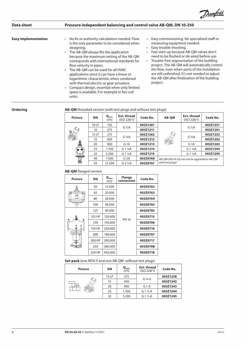
Combinations AB-QM with electrical actuators (AB-QM DN 10-100) 1)
Valvetype Stroke(mm) TWA-Z 3) AMI 140 ABNM AMV 110/120 NL
AME 110/120 NL AME 435 QM
Recommendedorderingcodenumbers(fordetailsrefertodatasheetsfortheseactuators)
082F1266NC,230V
082H8048 AMI140 24V,12s/mm, 2-pointcontrol
082F1191Thermalact.LOG24V(0-10V)
082F1193Thermalact.LIN24V(0-10V)
082H8056AMV110NL24V,24s/mm,3-pointcontrol
082H8057AME110NL24V,24s/mm,0-10V
082H0171AME435QM24V
DN10-20 2.25 ü ü ü ü -
DN25,32 4.50 ü 2) ü ü 4) ü -
DN40,50 10 - - - - ü
DN65-100 15 - - - - ü
1) Minimum recommended AB-QM setting is 20 %2) up to 60 % of Qmax3) Please be aware that only this type of TWA actuator is to be used with AB-QM4) up to 90% od Qmax
Additional actuator’s functionality available, for more info please contact your local Danfoss organization.
Closing point (measure) for DN 10-32
10.4
±0.
3

6 VD.C6.Q5.02 © Danfoss 11/2011 SMT/SI
Data sheet Pressure independent balancing and control valve AB-QM, DN 10-250
Technical data
AB-QM (thread version)
Nominal diameter DN 10 Low Flow 10 15
Low Flow 15 20 25 32 40 50
Flowrange
Qmin(20%)3)
l/h
30 55 55 90 180 340 640 1.500 -
Qmin(40%)3) - - - - - - - - 5.000
Qmax(100%) 150 275 275 450 900 1.700 3.200 7.500 12.500
Diff.pressure1) kPa 16-400 20-400 30-400
Pressurestage PN 16
Controlrange Acc.tostandardIEC534controlrangeishighasCvcharacteristicislinear(1:3000)
Controlvalve’scharacteristic Linear(couldbeconvertedbyactuatortoequalpercentage)
Leakageacc.tostandardIEC534 Novisibleleakage(at100N) max.0.05%ofQmax at500N
Forshutofffunction Acc.toISO5208classA-novisibleleakage
FlowmediumWaterandwatermixtureforclosedheatingandcoolingsystemsaccordingtoplanttypeIforDINEN14868.
WhenusedinplantTypeIIforDINEN14868appropriateprotectivemeasuresaretaken. TherequirementsofVDI2035,part1+2areobserved.
Mediumtemperature °C −10...+120
Stroke mm 2.25 4.5 10
Connectionext.thread(ISO228/1) G ½ A G ½ A G ¾ A G ¾ A G 1 A G 1¼ A G 1½ A G 2 A G 2½ A
actuator M30×1.5 Danfossstandard
Materials in the water
Valvebodies Brass(CuZn40Pb2-CW617N) GreyironEN-GJL-250(GG25)
MembranesandO-rings EPDM
Springs W.Nr.1.4568,W.Nr.1.4310
Cone(Pc) W.Nr.1.4305CuZn40Pb3-CW614N,
W.Nr.1.4305
Seat(Pc) EPDM W.Nr.1.4305
Cone(Cv) CuZn40Pb3-CW614N
Seat(Cv) CuZn40Pb2-CW617N W.Nr.1.4305
Screw StainlessSteel(A2)
Flatgasket NBR
Sealingagent(onlyforvalveswithtestplugs) DimethacrylateEster
Materials out of the water
Plasticparts PA POM
Insertpartsandouterscrews CuZn39Pb3-CW614N;W.Nr.1.4310;W.Nr.1.4401 -1) Δp = (P1–P3) min~max2) according suitability and usage especially in not oxygen tight systems please mind the instructions given by the coolant producer3) Flow limitations below Qmin is possible. Regardless of the flow limitations valve can modulate till 0 % of the settings.Pc - pressure controller partCv - Control valve part
Ordering (continuous) Combinations AB-QM with electrical actuators (AB-QM, DN 125-250)
Valvetype Stroke(mm)
AME 55 QM AME 85 QM
Recommendedorderingcodenumbers(fordetailsrefertodatasheetsfortheseactuators)
082H307824V,8s/mm,0-10V
082G1453 24V,8s/mm,0-10V
DN 125 25 ü -
DN 150 25 ü -
DN 200 27 - ü
DN 250 27 - ü
Operational pressure for all AB-QM valves is 4 bar. Closing pressure for all actuators is 6 bar.Additional actuator’s functionality available, for more info please contact your local Danfoss organization.

7VD.C6.Q5.02 © Danfoss 11/2011SMT/SI
Data sheet Pressure independent balancing and control valve AB-QM, DN 10-250
Technical data (continuous) AB-QM(flangeversion)
Nominal diameter DN 50 65 80 100
FlowrangeQmin(40%)
2)
l/h5.000 8.000 11.200 15.200
Qmax(100%) 12.500 20.000 28.000 38.000
Diff.pressure1) kPa 30-400
Pressurestage PN 16
Controlrange Acc.tostandardIEC534controlrangeishighasCvcharacteristicislinear.(1:3000)
Controlvalve’scharacteristic Linear(couldbeconvertedbyactuatortoequalpercentage)
Leakageacc.tostandardIEC534 max.0.05%ofQmaxat500N
Forshutofffunction Acc.toISO5208classA-novisibleleakage
Flowmedium
WaterandwatermixtureforclosedheatingandcoolingsystemsaccordingtoplanttypeIforDINEN14868.
WhenusedinplantTypeIIforDINEN14868appropriateprotectivemeasuresaretaken.TherequirementsofVDI2035,part1+2areobserved.
Mediumtemperature °C −10...+120
Stroke mm 10 15
Connectionflange PN 16
actuator Danfossstandard
Materials in the water
Valvebodies GreyironEN-GJL-250(GG25)
Membranes/Bellow EPDM
O-rings EPDM
Springs W.Nr.1.4568,W.Nr.1.4310
Cone(Pc) CuZn40Pb3-CW614N,W.Nr.1.4305
Seat(Pc) W.Nr.1.4305
Cone(Cv) CuZn40Pb3-CW614N
Seat(Cv) W.Nr.1.4305
Screw StainlessSteel(A2)
Flatgasket NBR
Nominal diameter DN 125 125 HF 150 150 HF 200 200 HF 250 250 HF
FlowrangeQmin(40%)
2)
l/h36.000 48.000 58.000 91.600 76.000 120.000 112.000 176.800
Qmax(100%) 90.000 120.000 145.000 229.000 190.000 300.000 280.000 442.000
Diff.pressure1) kPa 30-400(60-400forHFversion)
Pressurestage PN 16
Controlrange Acc.tostandardIEC534controlrangeishighasCvcharacteristicislinear.
Controlvalve’scharacteristic Linear(couldbeconvertedbyactuatortoequalpercentage)
Leakageacc.tostandardIEC534 max.0.01%ofQmaxat650N
max.0.01%ofQmax at1000N
Flowmedium
WaterandwatermixtureforclosedheatingandcoolingsystemsaccordingtoplanttypeIforDINEN14868.
WhenusedinplantTypeIIforDINEN14868appropriateprotectivemeasuresaretaken.TherequirementsofVDI2035,part1+2areobserved.
Mediumtemperature °C −10...+120
Stroke mm 25 25 27 27
Connectionflange PN 16
actuator Danfossstandard
Materials in the water
Valvebodies GreyironEN-GJL-250(GG25)
Membranes/Bellow W.Nr.1.4571 EPDM
O-rings EPDM
Springs W.Nr.1.4401 W.Nr.1.4310
Cone(Pc) W.Nr.1.4404NC W.Nr.1.4021
Seat(Pc) W.Nr.1.4027
Cone(Cv) W.Nr.1.4404NC W.Nr.1.4021
Seat(Cv) W.Nr.1.4027
Screw W.Nr.1.1181
Flatgasket Graphitegasket Nonasbestos
1) Δp = (P1–P3) min~max 2) Flow limitations below Qmin is
possible. Regardless of the flow limitations valve can modulate till 0% of the settings.
3) according suitability and usage especially in not oxygen tight systems please mind the instructions given by the coolant producer
Pc - pressure controller partCv - Control valve part

8 VD.C6.Q5.02 © Danfoss 11/2011 SMT/SI
1
5
6
7
8
2
3
4
1
2
3
45
6
7
8
Data sheet Pressure independent balancing and control valve AB-QM, DN 10-250
Design
1 Spindle 2 Stuffingbox 3 Pointer 4 Controlvalve’scone 5 Membrane 6 Mainspring 7 Hollowcone(pressure
controller) 8 Vulcanizedseat(pressure
controller)
1. Differential pressure controller DPC Thedifferentialpressurecontrollermaintainsaconstantdifferentialpressureacrossthecontrolvalve.Thepressuredifference ΔpCv(P2-P3)onthemembraneisbalancedwiththeforceofthespring.Wheneverthedifferentialpressureacrossthecontrolvalvechanges(duetoachangeinavailablepressure,ormovementofthecontrolvalve)thehollowconeisdisplacedtoanewpositionwhichbringsanewequilibriumandthereforekeepsthedifferentialpressureataconstantlevel.
2. Control valve Cv Thecontrolvalvehasalinearcharacteristic.ItfeaturesastrokelimitationfunctionthatallowsadjustmentoftheKvvalue.Thepercentagemarkedonthescaleequalsthepercentageof100%flowmarkedonthepointer.Changingthestrokelimitationisdonebyliftingtheblockingmechanismandturningthetopofthevalvetothedesiredposition,showedonthescaleasapercentage.Ablockingmechanismautomaticallypreventsunwantedchangingofthesetting.
Function:TheAB-QMvalveconsistsoftwoparts:1. Differentialpressure
controller2. Controlvalve
P1P3P2
P2-P3
P1-P3Δp = (P1-P3)ΔpCv = (P2-P3)
AB-QM DN 10-32

9VD.C6.Q5.02 © Danfoss 11/2011SMT/SI
P1 P3
Data sheet Pressure independent balancing and control valve AB-QM, DN 10-250
AB-QM DN 40, 50
AB-QM DN 50-100
Design (continuous)
1. Shutoffscrew 2. Mainspring 3. Membrane 4. DPcone 5. Seat 6. Valvebody 7. Controlvalvescone 8. Lockingscrew 9. Scale 10. Stuffingbox 11. Spindle
AB-QM DN 150
P1 P3
1. Valvebody 2. Valveseat 3. DPCcone 4. CVcone 5. Controllercasting 6. Rollingdiaphragm 7. Adjustingscrew 8. Bellowforpressurereliefon
DPCcone
AB-QM DN 125
P3P1
10 VD.C6.Q5.02 © Danfoss 11/2011 SMT/SI
P3P1
Data sheet Pressure independent balancing and control valve AB-QM, DN 10-250
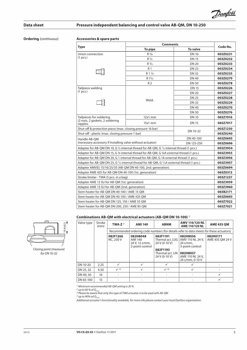
Design (continuous)
1. Valvebody 2. Valveseat 3. DPCcone 4. CVcone 5. Controllercasting 6. Rollingdiaphragm 7. Adjustingscrew 8. Bellowforpressurereliefon
DPCcone
AB-QM DN 200, 250

11VD.C6.Q5.02 © Danfoss 11/2011SMT/SI
Data sheet Pressure independent balancing and control valve AB-QM, DN 10-250
Thread version Flange version
Sizing
12 VD.C6.Q5.02 © Danfoss 11/2011 SMT/SI
Data sheet Pressure independent balancing and control valve AB-QM, DN 10-250
Sizing (continuous)
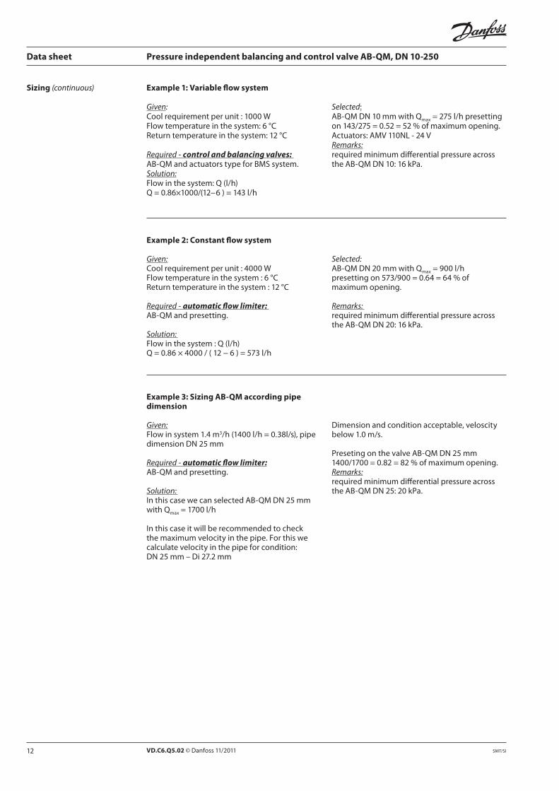
Example 1: Variable flow system
Given: Coolrequirementperunit:1000WFlowtemperatureinthesystem:6°CReturntemperatureinthesystem:12°C
Required-control and balancing valves: AB-QMandactuatorstypeforBMSsystem.Solution: Flowinthesystem:Q(l/h)Q=0.86×1000/(12−6)=143l/h
Selected: AB-QMDN10mmwithQmax=275l/hpresettingon143/275=0.52=52%ofmaximumopening.Actuators:AMV110NL-24VRemarks: requiredminimumdifferentialpressureacrosstheAB-QMDN10:16kPa.
Example 2: Constant flow system
Given: Coolrequirementperunit:4000WFlowtemperatureinthesystem:6°CReturntemperatureinthesystem:12°C
Required-automatic flow limiter: AB-QMandpresetting.
Solution: Flowinthesystem:Q(l/h)Q=0.86×4000/(12−6)=573l/h
Selected: AB-QMDN20mmwithQmax=900l/hpresettingon573/900=0.64=64%ofmaximumopening.
Remarks: requiredminimumdifferentialpressureacrosstheAB-QMDN20:16kPa.
Example 3: Sizing AB-QM according pipe dimension
Given: Flowinsystem1.4m3/h(1400l/h=0.38l/s),pipedimensionDN25mm
Required-automatic flow limiter: AB-QMandpresetting.
Solution: InthiscasewecanselectedAB-QMDN25mmwithQmax=1700l/h
Inthiscaseitwillberecommendedtocheckthemaximumvelocityinthepipe.Forthiswecalculatevelocityinthepipeforcondition: DN25mm–Di27.2mm
Dimensionandconditionacceptable,veloscitybelow1.0m/s.
PresetingonthevalveAB-QMDN25mm1400/1700=0.82=82%ofmaximumopening.Remarks: requiredminimumdifferentialpressureacrosstheAB-QMDN25:20kPa.
13VD.C6.Q5.02 © Danfoss 11/2011SMT/SI
Q
P2-P3
P2-P3
Blue
Red
P2-P3
Q=const. Q=const.
Pump optimization
Q
16kP a 400kPa
P1-P3
P1-P3
P1 P2 P3
(20kPa)
P1P3P2
P2-P3
P1-P3
DN40-100 DN10-32
Qnom=const
Data sheet Pressure independent balancing and control valve AB-QM, DN 10-250
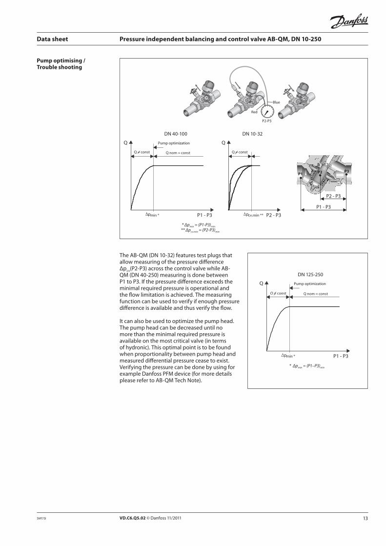
Pump optimising / Trouble shooting
* Δpmin = (P1-P3)min
** Δpcv.min = (P2-P3)min
Qnom=const
DN125-250
* Δpmin = (P1–P3)min
TheAB-QM(DN10-32)featurestestplugsthatallowmeasuringofthepressuredifferenceΔpcv(P2-P3)acrossthecontrolvalvewhileAB-QM(DN40-250)measuringisdonebetweenP1toP3.Ifthepressuredifferenceexceedstheminimalrequiredpressureisoperationalandtheflowlimitationisachieved.Themeasuringfunctioncanbeusedtoverifyifenoughpressuredifferenceisavailableandthusverifytheflow.
Itcanalsobeusedtooptimizethepumphead.Thepumpheadcanbedecreaseduntilnomorethantheminimalrequiredpressureisavailableonthemostcriticalvalve(intermsofhydronic).Thisoptimalpointistobefoundwhenproportionalitybetweenpumpheadandmeasureddifferentialpressureceasetoexist.VerifyingthepressurecanbedonebyusingforexampleDanfossPFMdevice(formoredetailspleaserefertoAB-QMTechNote).
14 VD.C6.Q5.02 © Danfoss 11/2011 SMT/SI
10%100%
① ② ④
≠h h+2mm,DN10-20
h+4mm,DN25-32
③
Data sheet Pressure independent balancing and control valve AB-QM, DN 10-250
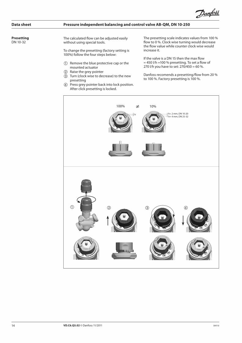
PresettingDN10-32
Thecalculatedflowcanbeadjustedeasilywithoutusingspecialtools.
Tochangethepresetting(factorysettingis100%)followthefourstepsbelow:
① Removetheblueprotectivecaporthemountedactuator
② Raisethegreypointer③ Turn(clockwisetodecrease)tothenew
presetting④ Pressgreypointerbackintolockposition.
Afterclickpresettingislocked.
Thepresettingscaleindicatesvaluesfrom100%flowto0%.Clockwiseturningwoulddecreasetheflowvaluewhilecounterclockwisewouldincreaseit.
IfthevalveisaDN15thenthemaxflow=450l/h=100%presetting.Tosetaflowof270l/hyouhavetoset:270/450=60%.
Danfossrecomendsapresetting/flowfrom20%to100%.Factorypresettingis100%.

15VD.C6.Q5.02 © Danfoss 11/2011SMT/SI
Note: DN 125 & 150: 1 turn = 6.0 %DN 200 & 250: 1 turn = 5.5 %
Note: 1 turn = 10%
Data sheet Pressure independent balancing and control valve AB-QM, DN 10-250
Service DN 10-32Fortheserviceshutofffunction,itisrecommendedtoinstallthevalveinthesupplywaterpipe.
Valvesareequippedwithplasticshut-offmechanismthatistobeusedforisolatingfunctionupto1bardifferentialpressure.Whenclosingagainsthigherdifferentialpressurepleaseuseaccessory-shut-off&protectionpiece(003Z1230)orsetthevalueto0%.
Installing AB-QMvalveismono-directionalmeaningthatthevalveoperateswhenarrowonthevalvebodyisalignedwithflowdirection.Whenthisruleisdisobeyedthevalveactslikevariableorificethatcausewaterhammeratsuddenclosingwhenavailablepressurehasincreasedorvalvehavebeensettolowervalue.
Incasewhensystemconditionallowsbackflowsitisstronglyrecommendedtousebackflowpreventerinordertoavoidpossiblewaterhammerthatcandamagethevalveaswellasotherelementsinthesystem.
DN 40-100 (125- 250)Fortheserviceshutofffunction,thevalvecanbeinstalledineithersupplyorreturnpipe. Valvesareequippedwithmanualshut-offforisolatingfunctionupto16bar.
+
–
Presetting (continuous)
DN125-250
DN40-100
Setting 60%
+
–
Max 25Nm

16 VD.C6.Q5.02 © Danfoss 11/2011 SMT/SI
Data sheet Pressure independent balancing and control valve AB-QM, DN 10-250
1.Thepressureindependentbalancingandcontrolvalveshouldbecomprisedofalinearcontrolvalveandanintegratedmembranebasedpressurecontroller.
2.ThepressureindependentbalancingandcontrolvalveshouldbeavailableintherangefromDN10-250.
3.Thevalvecouldbeusedasanautomaticflowlimiter.4.Thevalveshouldhaveamechanismtoadjusttheflowsteplessfrom100to0%ofthemaximum
flow.5.Minimumpossibleflowincombinationwithamodulatingactuatorshouldbe30l/h.6.Attheminimumsettingof30l/hmodulationto0%oftheflowshouldbepossible.7.Shutoffservicefunctionshouldbepossiblewithsettingmechanism.8.TheadjustmentshouldbeperformedwithoutatoolfordimensionsuptoDN32orastandardtool
forvalvesbiggerthanDN32.9.Thesetting,whichcanbelocked,shouldbevisiblefromthetopforvalvesDN32andfromtheside
forDN40-250.10.ThecontrolvalvestuffingboxshouldbeserviceableunderpressureforvalvesuptoDN32.11.Thevalvesshouldhaveashut-offfunction(positive),separatedfromthesettingmechanism,for
valvesDN40-250.12.Theleakagerateshouldbe:Novisibleleakageatforceofthethermalactuator(90N)forvalves
uptoDN32andforvalvesuptoDN1000.05%ofthekvat500N.Allactuatorsshouldbeabletocloseagainst600kPadifferentialpressure.
13.Theauthorityofthepressureindependentcontrolvalveshouldbe1atallsettings(controlvalvecharacteristicisnotchanged).
14.Controlvalveshouldhaveflow–controlsignalasalinearcharacteristicatallsettings.Controlratioofthepressureindependentbalancingandcontrolvalveshouldbehigherthan1:300(Supplier of the valve should provide lab test results 1)).
15.Controlvalveshouldhavethepossibilitytochangelinearcharacteristictoequalpercentagecharacteristicatallsizesandsettingsbyadjustingactuatorsettings.
16.Minimumstartingdifferentialpressureforflowlimitationshouldbe16kPaforvalvesuptoDN20,20kPavalvesuptoDN32.(Supplier of the valve should provide lab test results 1)).Nominalpressurerating16bar(PN20onrequest),maximaltestpressure25bar.
17.TestplugforpumpoptimizationandflowverificationshouldbeavailableforDN10-250.
Nominaldiameter: ________Connection: ________ Adjustmentrangefrom-to ________ m3/hProducedby: DanfossType: AB-QMOrderingno.: 003Z ____
1) Since there is no standard for testing procedure, Danfoss recommends verification by independent lab to compare control and flow limitation function of different PIBCVs at the same basis.
Tender text
17VD.C6.Q5.02 © Danfoss 11/2011SMT/SI
Data sheet Pressure independent balancing and control valve AB-QM, DN 10-250
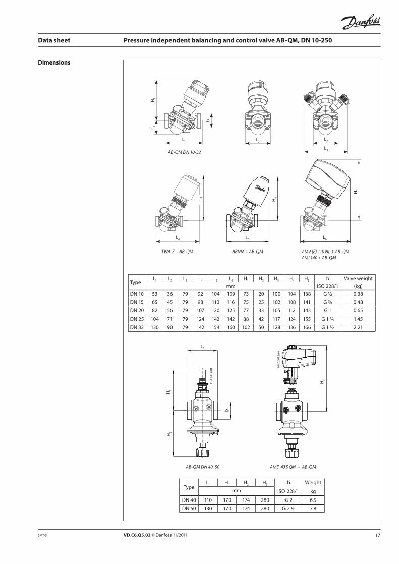
TypeL1 L2 L3 L4 L5 L6 H1 H2 H3 H4 H5 b Valveweight
mm ISO 228/1 (kg)
DN 10 53 36 79 92 104 109 73 20 100 104 138 G ½ 0.38
DN 15 65 45 79 98 110 116 75 25 102 108 141 G ¾ 0.48
DN 20 82 56 79 107 120 125 77 33 105 112 143 G 1 0.65
DN 25 104 71 79 124 142 142 88 42 117 124 155 G 1 ¼ 1.45
DN 32 130 90 79 142 154 160 102 50 128 136 166 G 1 ½ 2.21
Dimensions
TypeL1 H1 H2 H3 b Weight
mm ISO 228/1 kg
DN40 110 170 174 280 G 2 6.9
DN 50 130 170 174 280 G 2 ½ 7.8
AB-QM DN 40, 50
H1
L2
b
H2
AME 435 QM + AB-QM
H3
TWA-Z + AB-QM
H3
L4
AMV (E) 110 NL + AB-QMAMI 140 + AB-QM
H5
L6
H4
ABNM + AB-QM
L5
L2
L3
L2
H2
H1
b
L1
AB-QM DN 10-32

18 VD.C6.Q5.02 © Danfoss 11/2011 SMT/SI
Data sheet Pressure independent balancing and control valve AB-QM, DN 10-250
Dimensions (continuous)
TypeL1 H1 H2 H3 a
(EN1092-2)Weight(kg)mm
DN 50 230 170 174 280 165 14.2
DN 65 290 220 172 330 185 38.0
DN 80 310 225 177 335 200 45.0
DN 100 350 240 187 350 220 57.0
H2
L1
a
H1
AB-QM DN 50-100
H3
AME 435 QM + AB-QM

19VD.C6.Q5.02 © Danfoss 11/2011SMT/SI
Data sheet Pressure independent balancing and control valve AB-QM, DN 10-250
Dimensions (continuous)
H3
AME 55 QM + AB-QM DN 125
H3
AME 55 QM + AB-QM DN 150
TypeL1 H1 H2 H3 a Weight
mm (EN1092-2) (kg)
DN 125 400 272 518 507 250 85.3
DN 150 480 308 465 518 285 138
L1
H2
H1
aAB-QM DN 125 AB-QM DN 150
H2
H1
L1
a
20 VD.C6.Q5.02 ProducedbyDanfossA/S©11/2011
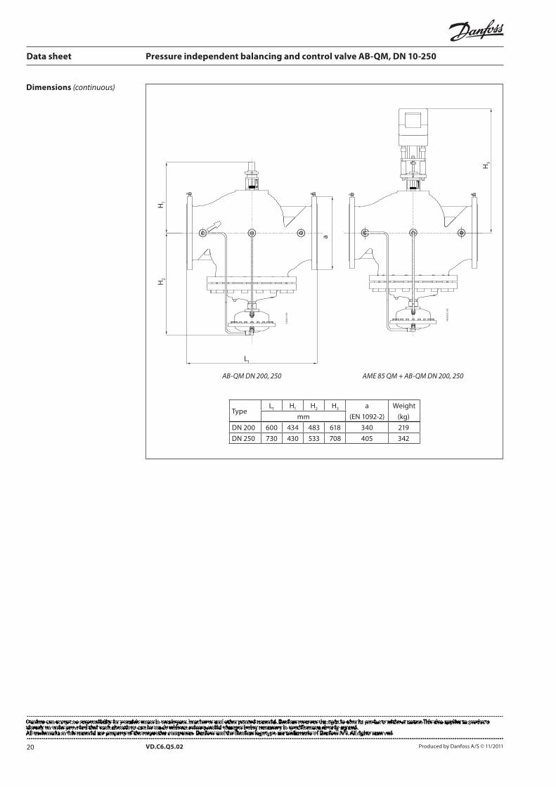
Data sheet Pressure independent balancing and control valve AB-QM, DN 10-250
H3
AME 85 QM + AB-QM DN 200, 250
a
L1
H2
H1
AB-QM DN 200, 250
TypeL1 H1 H2 H3 a Weight
mm (EN1092-2) (kg)
DN 200 600 434 483 618 340 219
DN 250 730 430 533 708 405 342
Dimensions (continuous)


![User guide for the balancing spread sheet MiniBalance...guidebook on commissioning/TAB (testing, adjusting & balancing) of duct systems, such as references [1] to [4]. The literature](https://static.fdocuments.us/doc/165x107/601e812c080755079b649f41/user-guide-for-the-balancing-spread-sheet-minibalance-guidebook-on-commissioningtab.jpg)