DATA SHEET C2-30 - Concens
4
The C2-30 is designed for operating two Concens actuators in parallel. Synchronization is achieved by adjusting actuator speed during operation. Failure to synchronize will result in the actuators stopping, this way possible mechanical stress and breakage can be avoided. Additionally the C2-30 includes current limiter and power stage temperature protection. The C2-30 has adjustable start and stop ramps for smooth operation. The C2-30 works in conjunction with actuators with hall sensors only. The basic control is done with Forward-, Backward-, and Stop-commands, either in continuous mode or pulse mode. Calibration input is for operating the system to its initial position. This is done with low speed. A wide range of parameters can be altered to suit to different demands and applications. The parameters are set by using the handy interface C2-PROG or by using the C2-USB dongle and your computer. Both must be connected to the red connector on the PCA. This datasheet is related to C2-30 firmware version 2.5 (v2.5) only. GB DATA SHEET C2-30 Advanced Actuator Controller Kim Svane Brinch, manager for mechanical development, with the new Gerber Spreader XLs 125-spreader Features Synchronized Current and temperature protection Settable drive speed Adjustable start- and stop ramp Different control modes Wide range of parameters Easy setting with serial interface Good repeatability of settings Autobalance feature Supply Voltage 12/24 VDC, filtered less than 20 % ripple Quiescent current 15 mA Motor current 2 x 10 A cont. 2 x 20 A 25 % duty PWM frequency 2 kHz Current limit 1 - 20 A Temperature limit 120 °C (Power stage) Ramp times 0 - 2 sec Pulse input freq. max. 1 kHz Pulse inputs pull- up/down 10 kΩ (Hi/Lo; 4 - 30 V/0 - 1 V) Control inputs 0 - 1 V = OFF; 4 - 30 V = ON (impedance 10 kΩ) Fault output Active, pull down max. 50 mA Aux. voltage output 5,4 V/20 mA Dimensions 78 x 73 x 25 mm (L x W x H) Operating temp. (Ta) - 20 °C to + 60 °C Weight of board 106 g CE Electromagnetic compatibility Industrial Environment Technical Data DATA SHEET | C2-30 v2.5 | February 2021 | 1 C2-30 Check for updates at www.concens.com
Transcript of DATA SHEET C2-30 - Concens

The C2-30 is designed for operating two Concens actuators in parallel. Synchronization is achieved by adjusting actuator speed during operation.
Failure to synchronize will result in the actuators stopping, this way possible mechanical stress and breakage can be avoided. Additionally the C2-30 includes current limiter and power stage temperature protection. The C2-30 has adjustable start and stop ramps for smooth operation. The C2-30 works in conjunction with actuators with hall sensors only.
The basic control is done with Forward-, Backward-, and Stop-commands, either in continuous mode or pulse mode.
Calibration input is for operating the system to its initial position. This is done with low speed.
A wide range of parameters can be altered to suit to different demands and applications.
The parameters are set by using the handy interface C2-PROG or by using the C2-USB dongle and your computer. Both must be connected to the red connector on the PCA.
This datasheet is related to C2-30 firmware version 2.5 (v2.5) only.
GB
D A T A S H E E T C2-30 Advanced Actuator Controller
Kim Svane Brinch, manager for mechanical development, with the new
Gerber Spreader XLs 125-spreader
Features Synchronized Current and temperature protection Settable drive speed Adjustable start- and stop ramp Different control modes Wide range of parameters Easy setting with serial interface Good repeatability of settings Autobalance feature
Supply Voltage 12/24 VDC, filtered less than 20 % ripple
Quiescent current 15 mA
Motor current 2 x 10 A cont. 2 x 20 A 25 % duty
PWM frequency 2 kHz
Current limit 1 - 20 A
Temperature limit 120 °C (Power stage)
Ramp times 0 - 2 sec
Pulse input freq. max. 1 kHz
Pulse inputs pull- up/down 10 kΩ (Hi/Lo; 4 - 30 V/0 - 1 V)
Control inputs 0 - 1 V = OFF; 4 - 30 V = ON (impedance 10 kΩ) Fault output Active, pull down max. 50 mA
Aux. voltage output 5,4 V/20 mA
Dimensions 78 x 73 x 25 mm (L x W x H)
Operating temp. (Ta) - 20 °C to + 60 °C
Weight of board 106 g
CE Electromagnetic compatibility
Industrial Environment
Technical Data
D A T A S H E E T | C2-30 v2.5 | February 2021 | 1
C2
-30
Check for updates at www.concens.com

FIG. 1
D A T A S H E E T
FIG. 2
Screw Terminals1 GND (0 V) + (blue wire for hall)
2 Supply 12/24 VDC (fuse required)
3 Actuator A +
4 Actuator A -
5 Actuator B +
6 Actuator B -
7 Hall b motor A (green)
8 Hall a motor A (yellow)
9 Forward(out) pos. command only
10 Backward(in) pos. command only
11 Hall b motor B (green)
12 Hall a motor B (yellow)
13 Stop, input for external stop input Pos. command only.
14 5,4 V/20 mA output for Hall and controls e.g. FW/BW command (brown wire for hall)
15 Fault output, active low on alarm. Open collector.
16 Calibration, pos. command starts calibration routine.
Connect motors and supply as in picture.
Inputs/Outputs Pulse A and B are for incoming feedback pulse-lines. Parameter 13 must be set to “1” .
FW & BW are command inputs forward/backward.
STOP input is for the use of external stop command (eg. end switches).
Calibration input is for starting the calibration routine.
FAULT output - refer to fault situations on page 3
INPUTS: 4 V - 30 V as “high” signal level and 0 V - 1 V as “low” signal level
OUTPUT: NPN open collector max. 50 mA
Config.X8
Fault-led
Trim in logic
Pulse in logic
C2-30
1 2 3 4 5 6 7 8 9 10 11 12 13
14 15 16
MOTORA
MOTORBHall a Hall aHall b Hall b
+ +- -
0 V
12 V/24 VDC
Calibr. in Fault out
Stop in
FW BW 5VOut
+A -A +B -B
Hal
l bA
Hal
l aA
Hall aB
Hall bB
Actuator A Actuator B
Config.
X8
C2-30
1 2 3 4 5 6 7 8 9 10 11 12 1314 15 16
78 mm
73 m
m
66 m
m
70 mm
Tolerences ± 0,1 mm
2 | D A T A S H E E T | C2-30 v2.5 | February 2021
Note: Color combination is example only
C2
-30

Running Speed is the speed which is used in normal mode. Calibration Speed is the low speed used during calibration-
routine. Start- and stop ramps define the acceleration and
deceleration time from 0 - 100 % and back to 0 speed. Current limit is limit value for current trip. If current value is
exceeded the motors will be stopped. During the period of start ramp + 1 sec the current limit is 1,5 times the current limit set value. Refer to datasheet for actual actuator for maximun current recommended when adjusting. Current limit value goes for both actuators (when limit is set to 20 it means 2 A for each actuator).
Difference limit is the value for largest allowable difference between A an B pulse counters. If value is exceeded motors will be stopped.
Adjust behavior defines how fast and intensively the controller will adjust the synchronization between motors A and B. Smooth 1 → Aggressive 10.
I-trip-indication – fault output can be set to “on” (default) also in current trip situation.
Start condition enables the device to re-start the motor to both or only to opposite direction after a trip or stop situation.
Control Mode sets the control-mode. In continuous mode the motor runs as long as command (fw or bw) is “on”. In impulse mode a short command starts the motor and the direction is changed with opposite command. Motor will stop only with “stop” command. In “Impulse-2” mode motor starts with short (fw/bw) impulse. Following command stops the motor, and next command (fw/bw) starts the motor again. In “Continous (4)” mode actuators run as long as buttons are activated and during calibration buttons must be activated too. Of course, in all modes the difference limit, current limit and stop-command will stop the motors.
Safety Reverse means automatic reverse run if the actuator has been stopped as a result of overload = I-trip. Stop input also triggers this function.
Auto-balance trigger parameter value sets the starting point for auto balance. Value is the number of pulses counted from mechanical home.
Double pulse mode enables the controller to handle actuators with double hall pulses. Must always be enabled when using Concens actuators.
End limit fw is a pulse counter “end stop” for fw direction. The positions is determined in pulse edges from 1–65535. Value 0 means that end stop is not in use. Note: This feature cannot be used in all combinations of gear ratio and stroke length due to number of pulses may exceed 65535.
Auto balance starts balancing routine before mechanical endstop. The trigger point is set with parameter 12. If “auto balance” is active it balances the system automatically in the end of stroke. This will prevent the possible pulse error accumulation. Auto balance always works to the calibration direction.
Calibration routine is a calibration cycle for balancing the system. Calibration can be started by giving fw and bw commands at the same time for 3 sec or with incoming signal to calibration input. Calibration routine can be interrupted with new FW or BW command or signal to STOP input. When calibration routine starts, both motors start to run to same direction and will run until current limit stops the motor or pulses stop coming. During the calibration routine the fault led is blinking slowly. When blinking stops and both motors have stopped the device has reset the pulse counters. Now the devise is ready for use. If there is need to change the calibration direction, swap the motor wires and the hall wires.
Status LED signalsMotor is jammed (current trip), pulses disappear or pulse counter difference is too high (difference limit). The controller will stop the motors and FAULT output will be pulled down (also in I-trip if indication is enabled). When motor is restarted the FAULT output is reset. Faults are also indicated with fault-led as follows:1 blink = position corrupted(calibration needed)2 blinks = current trip 3 blinks = pulses disappear4 blinks = difference limit5 blinks = temperature protection
JumpersThe Jumpers must be set to the position farthest to the right. (See FIG. 1)
MonitoringDuring normal use it is possible to monitor the function of controller with the C2-PROG. Select the monitor mode in C2-PROG and you can check the following values:1 current, Motor A 10 - 250 = 1 - 25 A2 current, Motor B 10 - 250 = 1 - 25 A3 pulse count/run cycle, only motor A4 pulse count difference5 position counter A 0 - 655356 position counter B 0 - 65535
Feedback PulsesThe controller counts pulse edges so counted value is double compared to the actual number of pulses.
D A T A S H E E T
Parameter list with: Quality Set range Default1 Running speed 40 – 100 % 40 – 100 100 (%)2 Calibration speed 20 – 60 % 20 – 60 60 (%)3 Start ramp 0 – 2 sec 0 – 20 0.5 (sec)4 Stop ramp 0 – 2 sec 0 – 20 0 (sec)5 Current limit 1 – 25 A 10 – 250 20 (2 A)6 Difference limit 3 – 50 pulses 3 – 50 10 (pulses)7 Behavior smo -> aggr 1 – 10 58 I-trip indication disa = 0; ena = 1 19 Start condition both dir = 0; only rev if I-trip = 1; only rev if stop = 2; only rev = 3 110 Control mode cont = 1; impuls = 2; impuls -2 = 3; 1 Cont + cont calibration = 411 Safety reverse time disa = 0; 1 – 30 reverse time after I-trip 0 (sec)12 Auto balance trigger disa = 0; 1 – 255 trigger point active 0 (pulses)13 Double pulse mode disa = 0; ena = 1 114 End limit FW disa = 0; FWD end limit = 1–65535 0 (pulses)
Parameter List Connect C2-PROG or PC to the Config-connector. This must be done with power on. C2-PROG displays the type of the device. Push the select button and you can scan the parameters with arrow buttons. Parameters are changed with +/- buttons. Store new settings with save button (press and hold for more than 5 sec).
D A T A S H E E T | C2-30 v2.5 | February 2021 | 3
Parameter Description
con35 con50 con60
Gear ratio I max. stroke/mm I max.
stroke/mm I max. stroke/mm
5 6325 4 12295 19 348914 2385 14 3510 43 152819 1706 17 2835 66 99727 1220 24 2047 81 80551 643 49 1003 100 65371 460 84 585
These are the maximum stroke lengths where “End limit FW” (65535) can be used.
C2
-30
D A T A S H E E T
Recommendations and warnings If power is cut while actuators are travelling, the new position is not memorized. Hence calibration or learning must be performed
to bring system back on track. Attention! C2-30 has no fuse in it. Use external fuse according to application. Please adjust max current to be 10 % higher than maximum current during load to ensure the longest actuator lifetime. Please ensure that the power supply for the controller is capable of supplying sufficient current - otherwise controller and
actuator may be damaged. Double-check correct polarity of power supply. If connected wrong C2-30 will be damaged. If wire colors differ from what is expected, please check with supplier or check on our YouTube channel before connecting the
actuator to the controller. Connect to power during programming.
C2-30 Item Number Combination
C2
-30
Concens A/SØresundsvej 7DK-6715 Esbjerg NDenmark
T +45 70 11 11 31F +45 76 10 50 10E [email protected] DK10132266www.concens.com
- excellent electric actuators
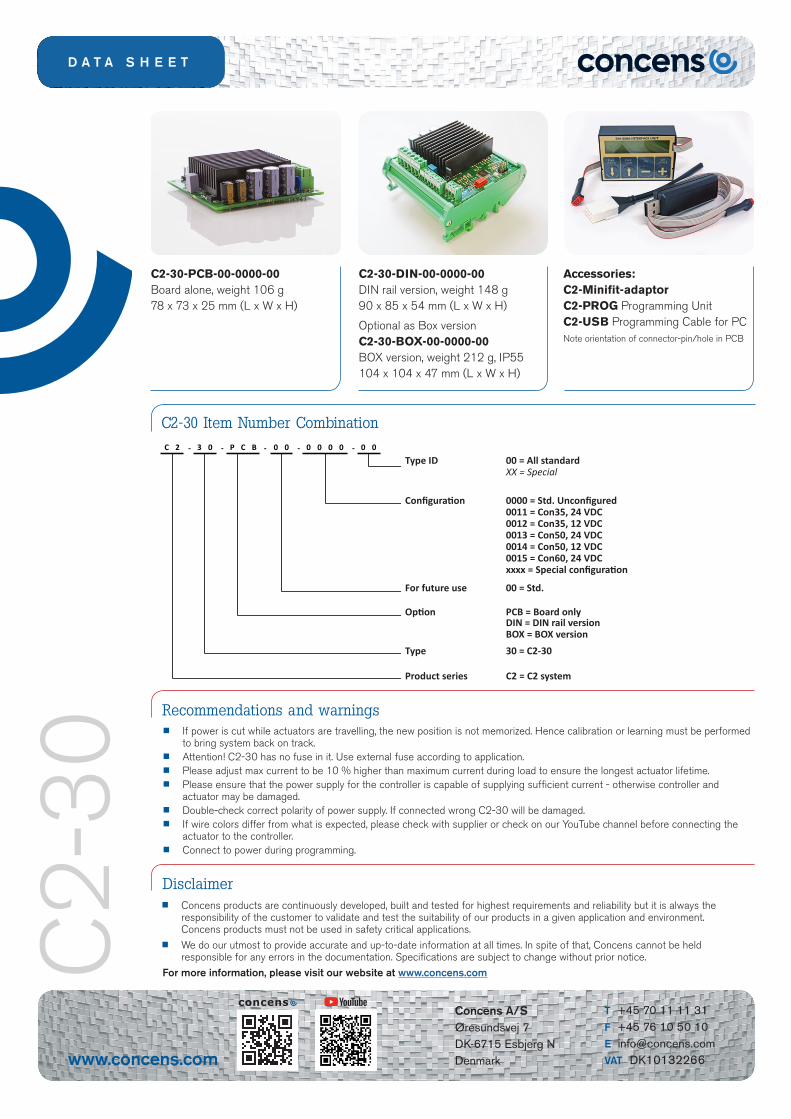
C2-30-PCB-00-0000-00 Board alone, weight 106 g78 x 73 x 25 mm (L x W x H)
C2-30-DIN-00-0000-00 DIN rail version, weight 148 g 90 x 85 x 54 mm (L x W x H)
Optional as Box version C2-30-BOX-00-0000-00 BOX version, weight 212 g, IP55 104 x 104 x 47 mm (L x W x H)
Accessories: C2-Minifit-adaptor C2-PROG Programming Unit C2-USB Programming Cable for PCNote orientation of connector-pin/hole in PCB
C2-‐30Part number combina3on
C 2 -‐ 3 0 -‐ P C B -‐ 0 0 -‐ 0 0 0 0 -‐ 0 0
Type ID 00 = All standardXX = Special
Configura3on 0000 = Std. Unconfigured0011 = Con35, 24 VDC0012 = Con35, 12 VDC0013 = Con50, 24 VDC0014 = Con50, 12 VDC
xxxx = Special configura3on
For future use 00 = Std.
Op3on PCB = Board only
Type 30 = C2-‐30
Product series C2 = C2 system
Bold le'ers = standard lead .meItalic le'ers = longer lead .me, ask Concens
DIN = DIN rail versionBOX = BOX version
0015 = Con60, 24 VDC
Type ID 00 = All standard XX = Special
Configuration 0000 = Std. Unconfigured 0011 = Con35, 24 VDC 0012 = Con35, 12 VDC 0013 = Con50, 24 VDC 0014 = Con50, 12 VDC 0015 = Con60, 24 VDC xxxx = Special configuration
For future use 00 = Std.
Option PCB = Board only DIN = DIN rail version BOX = BOX versionType 30 = C2‐30
Product series C2 = C2 system
Disclaimer Concens products are continuously developed, built and tested for highest requirements and reliability but it is always the
responsibility of the customer to validate and test the suitability of our products in a given application and environment. Concens products must not be used in safety critical applications.
We do our utmost to provide accurate and up-to-date information at all times. In spite of that, Concens cannot be held responsible for any errors in the documentation. Specifications are subject to change without prior notice.
For more information, please visit our website at www.concens.com