Data Management and Virtual Reality Applications of BIM models1238430/FULLTEXT01.pdf · Building...
65
IN DEGREE PROJECT COMPUTER SCIENCE AND ENGINEERING, SECOND CYCLE, 30 CREDITS , STOCKHOLM SWEDEN 2018 Data Management and Virtual Reality Applications of BIM models RICCARDO LEVANTE KTH ROYAL INSTITUTE OF TECHNOLOGY SCHOOL OF ARCHITECTURE AND THE BUILT ENVIRONMENT
Transcript of Data Management and Virtual Reality Applications of BIM models1238430/FULLTEXT01.pdf · Building...

IN DEGREE PROJECT COMPUTER SCIENCE AND ENGINEERING,SECOND CYCLE, 30 CREDITS
, STOCKHOLM SWEDEN 2018
Data Management and Virtual Reality Applications of BIM models
RICCARDO LEVANTE
KTH ROYAL INSTITUTE OF TECHNOLOGYSCHOOL OF ARCHITECTURE AND THE BUILT ENVIRONMENT


KTH Byggvetenskap
Civil and Architectural Engineering
Kungliga Tekniska Högskolan
Data Management and Virtual Reality
Applications of BIM models
Datahantering och Virtuell Verklighet Applikationer av BIM modeller
Masters Thesis in Building Technology
Nr 464
TRITA-ABE-MBT-18351
Civil and Architectural Engineering
2018 06 11
Riccardo Levante
Supervisor Kjartan Gudmundsson, KTH Byggvetenskap


Abstract
Nowadays new digital technologies play an important role in the AEC sector, which are going
through a significantly changing period. In this process BIM represent the main character,
revolutionizing the traditional way of working in the main operative phases: Design,
Construction and Maintenance. However, having all these aspects under a unique
methodology can brings several problems without a strong framework to regulate the whole
procedure. The huge quantity of information, as well as the high number of involved people,
are the main weak points, that can become the main strong points when Facility Management
is involved in the process. In this scenario this work will analyse a real project located in
Genova (Italy), seeing as a complex structure as an hospital can be regulated through the BIM
methodology.
The thesis will focus on two fundamental aspects of the new construction methodology: Data
Management and Virtual Reality. The first part aims to analyse correlation between BIM and
its information, focusing also on the study case, proposing operative solution through the BIM
software Revit and the visual programming toll Dynamo. The second part will show
advantage integrating virtual reality technologies in the AEC sector, showing how build an
interactive virtual simulation using the game engine software Unity based on our study case.
Through this work we have seen the importance of new technologies for the future of
Construction Industry, showing how important is the sharing information involving always
more people into the process, particularly for complex structures.
Data Management and Virtual Reality Applications of BIM models
2
Contents
1 Introduction ................................................................................................... 6
1.1 Scenario ......................................................................................................................... 6
1.2 Work Methodology ....................................................................................................... 6
2 The BIM methodology .................................................................................. 8
2.1 BIM Definition .............................................................................................................. 8
2.2 BIM and VR for AEC industry ................................................................................... 10 2.2.1 Design Phase ................................................................................................................... 10 2.2.2 Construction Phase .......................................................................................................... 11 2.2.3 Maintenance Phase .......................................................................................................... 11
2.3 BIM for Healthcare ..................................................................................................... 11
3 The Galliera Hospital .................................................................................. 13
3.1 The New Project .......................................................................................................... 14
3.2 BIM for the Galliera .................................................................................................... 16
4 Data Management ....................................................................................... 18
4.1 Data Standardisation ................................................................................................... 18 4.1.1 IFC and COBie ................................................................................................................ 20 4.1.2 Space Management and Data Population ........................................................................ 20 4.1.3 Data requirement system for a new project ..................................................................... 21
4.2 Methodology: Dynamo for Data Management ........................................................... 23 4.2.1 Identification of target and data ....................................................................................... 23 4.2.2 Dynamo ........................................................................................................................... 23 4.2.3 Dynamo for Export data – Application 1 ........................................................................ 24 4.2.4 Dynamo for Export data – Application 2 ........................................................................ 26 4.2.5 Dynamo for Export/Import data – Application 3 ............................................................ 27
4.3 Results ......................................................................................................................... 30
5 VR for Architectural visualization ............................................................ 32
5.1 VR application for AEC industry ................................................................................ 32
5.2 Methodology: From Revit to Unity ............................................................................. 33
5.3 Unity Workflow .......................................................................................................... 36 5.3.1 Virtual Environment Develop ......................................................................................... 37 5.3.2 Standalone game creation ................................................................................................ 38 5.3.3 Data Visualization ........................................................................................................... 40
5.4 Result ........................................................................................................................... 42
6 Conclusion .................................................................................................... 43
Reference ............................................................................................................ 44
Appendix 1 ......................................................................................................... 46

Data Management and Virtual Reality Applications of BIM models
3
Appendix 2 ......................................................................................................... 51
Appendix 3 ......................................................................................................... 54
Appendix 4 ......................................................................................................... 57

Data Management and Virtual Reality Applications of BIM models
4
List of Figures
Figure 1: BIM along the construction value chain (Word Economic Forum, 2016).................. 9
Figure 2: Aerial photo (Galliera, u.d.) ...................................................................................... 13
Figure 3: New project (Galliera, u.d.) ...................................................................................... 15
Figure 4:BIM standardization platform (Poljanšek, 2017). ...................................................... 19
Figure 6: Relationship between elements of information management (BSI, 2014) ............... 22
Figure 6: Anatomy of a Node (Dynamo) ................................................................................. 24
Figure 7: Dynamo script - Application 1 .................................................................................. 25
Figure 8: Dynamo Player (Dynamo) ........................................................................................ 26
Figure 9: Dynamo script – Application 2 ................................................................................. 27
Figure 10: Dynamo script – Application 3.1 ............................................................................ 28
Figure 11: Dynamo script – Application 3.2 ............................................................................ 29
Figure 12: Application 3 – Example......................................................................................... 30
Figure 13: Example of VR use with BIM model ..................................................................... 33
Figure 14: Revit – Unity interoperability process .................................................................... 34
Figure 15: Export/Import “.fbx” format file ............................................................................. 35
Figure 16: Export process from 3DS Max................................................................................ 35
Figure 17: Unity structure (Boeykens, 2013) ........................................................................... 36
Figure 18: Essential Step to Create a Virtual Environment ..................................................... 37
Figure 19: Unity Model interface ............................................................................................. 38
Figure 20: Standalone File Creation ......................................................................................... 39
Figure 21: Unity Walkthrough ................................................................................................. 39
Figure 22: Cube Game Object .................................................................................................. 40
Figure 23: C# script in Unity .................................................................................................... 41
Figure 24: Final steps Data Visualization................................................................................. 41
Figure 25: Unity Walkthrough Data Visualization................................................................... 42
Figure 26: Dynamo script – Application 1.1 ............................................................................ 46
Figure 27: Dynamo script – Application 1.2 ............................................................................ 47
Figure 28: Dynamo script – Application 1.3 ............................................................................ 47
Figure 29: Dynamo script - Application 1.4 ............................................................................. 48
Figure 30: Dynamo script - Appllication 1.5 ............................................................................ 49
Figure 31: Dynamo script – Application 1.6 ............................................................................ 50
Figure 32: Dynamo script – Application 2.1 ............................................................................ 51

Data Management and Virtual Reality Applications of BIM models
5
Figure 33: Dynamo script – Application 2.2 ............................................................................ 52
Figure 34: Dynamo script – Application 2.3 ............................................................................ 53
Figure 35: Dynamo script – Application 3.1.1 ......................................................................... 54
Figure 36: Dynamo script – Application 3.1.2 ......................................................................... 55
Figure 37: Dynamo script – Application 3.1.3 ......................................................................... 55
Figure 38: Dynamo script – Application 3.2.1 ......................................................................... 57
Figure 39: Dynamo script – Application 3.2.2 ......................................................................... 58
Figure 40: Dynamo script – Appllication 3.2.3 ........................................................................ 58
Figure 41: Dynamo script – Application 3.2.4 ......................................................................... 59
Data Management and Virtual Reality Applications of BIM models
6
1 Introduction
1.1 Scenario
The AEC (Architecture, Engineering and construction) industry is going through a period of
strong development. Many recent technologies start to be essential to ensure a successful
construction process and new engineering methods and tools provide to make possible
developing of smart cities. In this scenario, however, the facility delivery process remains
fragmented, and it depends on paper-based modes of communication. Errors and omissions in
paper documents often cause unanticipated field costs, delays, and eventual lawsuits between
the various parties in a project team (Eastman, 2011). These problems damage the whole
construction workflow, reducing the quality of the result. Often, in fact, without a correct
information methodology and with 2D-based communication process, it is common that only
on the last phase important analyses are done (cost-estimate, Energy-use analysis, structural
detail, etc.), where it is already too late.
Building Information Modeling (BIM) marks a turning point for the whole AEC industry,
improving collaboration, efficiency and productivity. This method represents one of the most
important revolutions in the construction sector, focusing the attention on the information
aspect of each project and contributing to improve well-designed Facility Management (FM)
systems. Data management, in fact, becomes the main character in the lifecycle of a building,
from the first draw until the maintenance plan, and in this context FM systems cover an
important role. BIM and FM aspire to solve all interoperability problems that always have
characterized the building sector.
After the information, another important point of BIM is the method based on 3D model,
which brings new possibilities of architecture visualization that no one could image. Virtual
reality (VR) technology, in fact, provides to cover the previous gap of architectural
communication, making possible to see the result before it is completed through a realistic
and immersive simulation of the project.
These aspects start to be necessary to cover the growing complexity of health care design,
where to manage a huge number of data and documentation, for all involved people,
represents a big challenge. New design technologies are essential in healthcare projects, to
ensure success both in design and construction phase but particularly in the operation and
maintenance phase. This because for healthcare buildings, differently for other structures,
non-professional people play an important role (patients, visitors, medical staff etc.) in the
whole building lifecycle, making essential to have a single database easily accessible for all
stakeholders.
1.2 Work Methodology
Starting from this background, this research aims to explain the role of BIM in the healthcare
field, focusing on the importance to make easier sharing information and architecture
visualization. The reasons of this choice come from the difficult to manage complex
buildings, as our study case, where several actors are involved in the process and where to
have a clear procedure is essential for the result. We will also analyze the possible issues that
can characterize a BIM process and how they can be solved through a methodology based on
data management and virtual reality.

Data Management and Virtual Reality Applications of BIM models
7
The report starts talking of the general BIM definitions to move then on the specific
relationship between BIM and VR and BIM for healthcare industry. The main part developed
for this project will concern the important aspect of data management in a digital FM
workflow based on BIM, starting from a theoretical focus on the standard regulation for this
sector. The applications developed for this part see as main character the software of visual
programming Dynamo, used to propose interactive method to make easier sharing data
between professional and non-professional people. The last part will be dedicated to present
some examples of VR uses for AEC industry, explaining the workflow to create a virtual
environment through the gaming software Unity.
In all this process our study case will have a leading role. It is represented from a new hospital
project that will be built in the city of Genova (Italy) by the public customer Ente Ospedaliero
Ospedali Galliera (EOOG).

Data Management and Virtual Reality Applications of BIM models
8
2 The BIM methodology
How said BIM stands for Building Information Modelling and/or “Management/Model”
according to the Making BIM a global success, Manifesto published by the European
Construction Industry Federation (FIEC), where it also specified that BIM is a process driven
working and management method based on collaboration and sharing data throughout the
entire construction value chain, including clients and final users. More generally it consists in
a practical database-centered working with the aim to use and analyze huge quantities of data
and information; representing the base of the overall digitalization of the construction sector
and “Industry 4.0”. In the last twenty years BIM has completely revolutionized the whole
AEC industries, setting significant changes not only in the lifecycle of a building but also in
the roles and relationships among a project team.
2.1 BIM Definition
If we think at the beginning of digital drawings, older CAD (Computer Aided Design)
systems were not so difference from the hand-drawing. They, in fact, were general file based
on line-types and layer identification to produce plotted drawings, that it basically the same to
draw with a pencil, but faster. In the future CAD systems have bene improved, first with the
introduction of 3D modelling and then with the ability to include additional information on
these files, but when the attention shifted from drawings and 3D images to data itself we can
see a turning point. BIM methodology have been introduced placing at the center the
importance to create and collect information, producing building models through interactive
tools able to support multiple different views of the data contained within a drawing set,
including 2D and 3D.
The NBIMS Initiative (National Building Information Modelling Standard) categorizes the
Building Information Model (BIM) three ways:
• As a Product;
• As some IT-enabled, open standards–based deliverable, and a collaborative Process;
• As a facility lifecycle management requirement.
These categories support the creation of the industry information value chain, defining BIM
as fundamentally different way of creating, using, and sharing building lifecycle data
(Eastman, 2011).
For the first time in the history of construction, data becomes the key for each phase of the
building lifecycle (Figure 1) amassing large volumes of high-integrity information.

Data Management and Virtual Reality Applications of BIM models
9
Figure 1: BIM along the construction value chain (Word Economic Forum, 2016)
How explained above BIM has revolutionized not only the design phase, but the whole
system, bringing many changes in construction, commissioning, operations, renovation and
even demolition phase. Plus, the algorithm generates new sectors and new method changing
the bases itself of the AEC industries. For example, new methods of simulation and virtual
reality help to identify interdependencies and clashes during the design and engineering stages
and enable a virtual experience of the building even in the early design stage (Poljanšek,
2017).
Other two concepts are essential to understand the real definition of BIM and its
differentiation from traditional 3D project; they are “parametric object” and
“interoperability”.
With the first one we don’t indicate an object with fixed properties and geometry, but an
object composed by parameters and rules that determines the geometry as well as some non-
geometric properties and features. The parameters and rules can be expressions that relate to
other objects, allowing the objects to automatically update according to user control or
changing contexts (Eastman, 2011). These objects are also based on “different levels of
aggregation”, which means that each element is related with its component, so it can be
managed interacting with any of this level. Technologies that allow users to produce building
models that consist of parametric objects are considered BIM authoring tools.
With the second aspect we mean the possibility to communicate and exchange data between
software, making easier and faster the workflow. Interoperability bring to be necessary a
standardization of data model, allowing to create a method to translate information from one
schema language to another. In this scenario two main products are important: IFC (Industries

Data Management and Virtual Reality Applications of BIM models
10
Foundation Classes) for planning, design, construction and management and CIS/2 (CIM steel
Integration Standard Version 2) for structural steel engineering and fabrication.
2.2 BIM and VR for AEC industry
Another purpose because BIM methodology was born is to improve the gap of
communication and understanding between different actors that we can find in each project,
to obtain a better workflow of the design process and a better quality of work. There are
different meanings because problems of communication are so common in this sector, but the
most common problem is that usually information is not presented in such a way that people
can understand it. In fact, one important lack in the BIM life cycle is to allow to non-technical
parties to cooperate in the design process.
In this context, real-time visualization and VR has been shown to offer an efficient
communication platform. It offers a natural medium for building design providing three-
dimensional visualization that can be manipulated in real-time and can be used collaboratively
to explore design options and simulate different stages of the construction process
(Bouchlaghem, 2005). The use of this technology is always more accessible since the
Building Information Model have assumed a principal position in the AEC field, indeed the
required 3D data can be extracted from the architect's own design environment, instead of
creating it from scratch using 2D-plans, elevations and sketches as a reference (Johansson M,
2014).
Virtual Reality can be described as a realistic and immersive simulation of a three
dimensional environmental generated by a computer in which a person can naturally interact
with the context by movement of the body (Milgram, 1995). The aim of this technology is to
replay the reality, as many as possible precise, and access to this interface via a computer
(monitor, keyboard, mouse) or with other device that can create an immersive experience.
There are numerous possibilities of application for VR technologies and the number increases
when we talk of big project, where there is a high number of people involved both in
realization phase and in management phase. This is the case of our project where the study
case is a hospital and consequently the actors aren’t only engineers and architects that design
the project, but also the end users of the building like patients, visitors, medical staff and
people assigned maintenance. Respect to other projects this needed to be understood from
several categories of people, all with difference knowledges and with difference point of view
respect the building. In this scenario VR technology can help people involved in the project
and not only for the Design process but also for the realization and management phase.
2.2.1 Design Phase
Nowadays this is the environment where we find more applications and solutions for the VR
technology in the building sector. Respect a 3D model which gives a limited experience of the
finished building, VR gives an immediate understanding of spaces and features creating a
realistic and immersive 3D simulation. This allow designer to explore and analyze the project
in a 1:1 scale with the ability of walking inside or around the structure, making much easier to
evaluate shape and design. In fact, for a correct hospital setting is important that end-users can
move safety and quickly, and that physicians and staff can access the appropriate equipment
easily. Using virtual reality, you have the possibility to evaluate the space disposition for each
part of the structure and making this decision early you can save significant amount of time in

Data Management and Virtual Reality Applications of BIM models
11
the realization phase. In the end other advantages are represented as a communication tool,
seeing as it makes more available to share information and ideas. This is useful for
professional people (architect, engineer, etc.) and others to understand better each features of
the project and to make easer and sliding the process.
2.2.2 Construction Phase
Some interesting applications about VR technologies concern also their use during building
construction phase to provide technical information to the AEC sector operators. The most
obvious benefit of virtual reality for construction companies is that it can save time and
money by allowing construction professionals to test any number of features before the
construction or installation phase starts. Each worker can analyze, with a suitable device, what
is the correct position of a generic element or where a specific system must be installed,
making easier obtain information and decreasing the possibility of errors. However also in
case of problems during the construction phase virtual reality can be useful for the process
evaluating the different proposed solutions directly on site.
Another Interesting application adopted by some construction company is to use VR
technology for construction site safety. It proved useful for construction site safety training
and to learn functions of operating heavy machinery, also explaining better the different site
hazards for professionals and visitors with the opportunity to recreate the same location of
building site.
2.2.3 Maintenance Phase
Virtual Reality is only in the initial state related with AEC industry but for sure Facility
Management and maintenance aspect is where VR has more potential. In a building is not
always possible access and analyze all the elements, usually we can find systems inside wall,
below the ground, behind a ceiling or in some troublesome place where it is dangerous to
access. This needs to spend time locating the source of the issue before being able to
implement a solution. With a virtual environment the worker can be helped to understand both
the location of mechanical systems and how this equipment interacts with each other.
Important is also the opportunity that virtual reality gives to analyze the buildings systems
without be present on site. With this solution is possible to recreate the environment wherever
you are and plus simulations can be run to see how a new equipment may impact existing
operations, increasing in this way the velocity of the process and the safety for the
intervention.
2.3 BIM for Healthcare
The healthcare industry is one of the largest and fastest-growing industries with a constant
development to keep up with needs of patients. Healthcare construction projects have become
increasingly complex and challenging from the facilities management perspective and
appropriate healthcare design is essential for ensuring health and promoting wellness
(Mohammadpour, 2017). To achieve a great healthcare design is essential that design team
involves in the construction process also stakeholder and medical staff (physicians, nurse
practitioners, physicians’ assistants). However, in a traditional design approaches with a 2D
drawings and documents used to explain the healthcare design, it becomes difficult for the
medical staff and stakeholders to understand the concept and content of those 2D drawings
because they lack engineering knowledge and experience (Okada R.C., 2017).

Data Management and Virtual Reality Applications of BIM models
12
In this scenario BIM represent a perfect solution because based on a 3D model technology
and on a single database used along all the design and construction process. This technology
related with healthcare and hospital needs during all the phases (design, construction and
management) ensure to save time and money avoiding possible errors and delays which are
very common in complicate projects like this. There are many advantages to adopt this
technology in the healthcare industries, first of all it supports the design process easily and it
makes possible to create a clear database with all the information. Then it can transform the
design idea into physicalizing and visualization and can be used for knowledge integration,
performance analysis, cost estimation, 4D (time schedule) simulation and crash detection.
Especially it exchanges information of the specific BIM model among different system,
software and organization in favor to integrate information and to improve the communication
efficiency (Collinge, 2012) (Cooney, 2012).
There are many previous researches using BIM methodology for healthcare projects. One of
this sees as case study the Careggi Hospital in Florence, which is part of the STREAMER
project with the aim to reduce the energy consumption and carbon dioxide pollutions for big
healthcare structures and in this particular case developing a semantic approach to design
starting from the combination of BIM and GIS systems (Iadanza E., 2015). Important is also
the project for the New Karolinska Hospital which represents one of the biggest projects in
healthcare in the County of Stockholm. The use of BIM was contractually mandatory, and
they adopted this method for the entire lifecycle, creating a single data platform on which
designers, contractors and eventually facility managers could collaborate. They started from
the design specifications and performance requirements until every object have been digitally
stored in the model, with its key attributes and exact location and with a final objects list of
about one million items (University of Waterloo, 2017). Another important example is the
work of Manning and Messner which have verified BIM adoption during the concept and
design phases of two healthcare projects, to provide visualization, time save, quantity take-
offs, and decision making (Manning, 2008). Also, the work of Khanzode Fisher and Reed
represent a role model, about the case study using BIM/VDC (virtual Design and
Construction) tool and process to coordinate the MEP systems of healthcare project in
Northern California (Khanzode, 2008).
These examples and the above argumentations explain how important BIM for healthcare
industry could be. Following this road, we will talk of our case study, showing the structure
and features of a real BIM project.

Data Management and Virtual Reality Applications of BIM models
13
3 The Galliera Hospital
Everyone knows how is important the role of a hospital in the city urban body and what is its
importance under the social and economic aspects. The case of Galliera Hospital and the
choice to build a new structure is particularly important since it is located to the center of
Genova, one of the cities with a more complex urban environment in Italy. These aspects
make difficult the whole building process, but they focus the attention on the methodology
choice to follow preventing each possible problem and reducing the environmental impact.
The historical part of the Galliera Hospital (Figure 2) was built around the 1877 and 1888,
located in the district of Carignano and near the Tyrrhenian coast, in an area with an irregular
altitude profile and highly urbanized. The nineteenth-century building is composed by:
• A long construction with a length of 260 meters and a curvilinear profile, with two
rectangular building situated at the extremes;
• Seven pavilions are inserted on the reverse side of the principal structure and each of
them is about 50 meters long.
Figure 2: Aerial photo (Galliera, u.d.)
In the last years the hospital was main character to develop the project INDICATE (Indicator-
based Interactive Decision Support and Information Exchange platform for Smart Cities),
which was promoted by the European Union with the aim to develop a useful interactive
software for all the people involved in the design and development phases of Smart Cities and
a Green Hospital. The software to develop had to be founded on a cloud platform allowing

Data Management and Virtual Reality Applications of BIM models
14
dynamic evaluations of the interaction between buildings, power grid, renewable energy
systems and ICT (Information and Communication Technology) resources. The principal
goal, as the official website declares, are:
• Plan using an energy-based decision support tool that can use dynamic simulation and
considers buildings and occupants, the urban environment and energy distribution
grids.
• Reduce energy consumption and CO2 emissions by indicating the impact of energy
conservation measures via dynamic simulation modelling.
• Integrate new technologies and services to manage supply and demand via dynamic
simulation modelling, GIS and 3D urban modelling.
• Optimize existing systems to enable local balancing through demand response and
tariff analysis, via dynamic simulation modelling of the interactions between buildings
and their occupants, installed systems and energy distribution grids in the urban
environment.
The subjects involved in the project have made available competences in several sectors like:
dynamic modelling and simulation; geographic information system (GIS); software for 3D
modelling (Cad3D-BIM); demand side management; urban sustainability indicator; integrate
solutions to minimize energy and fossil fuel consumption.
In this context Galliera Hospital is the contribution to the demonstration of the INDICATE
project and tools. It is, in fact, in the heart of the area chosen to develop the project, including
about 60 hectares with many public buildings such as police headquarters, schools and youth
centers which will be included in the study due to the relationship of the hospital with its
neighbors. The INDICATE project focuses attentions on the historical part mapping and on
designing of the new part through BIM software. All the information from the BIM model
and from the GIS software will be collected in the Virtual City Model (La Franca, 2016).
3.1 The New Project
The New Hospital project is born as reply to structural inadequacies of the existing structure
and with the aim to increase the healthcare efficiency in a city with a constant progression like
Genova. The nineteenth-century building presents several problems on the distributive
aspects, due also to the complex shape, and many difficulties to adapt it on the new healthcare
standards. The better choice to provide to these problems was to build a new hospital, next to
the older one (Figure 3Figure 3), adapt to carry out all the requests and utilizing the
technologies at the forefront in all the sectors.
After a period of standstill, the project of the whole New Hospital is moving on and it has
been divided into two lots:
• The first one (Lot 1) for the construction of the new structure in a highly urbanized
area, after some existing building are removed;

Data Management and Virtual Reality Applications of BIM models
15
• The second one (Lot 2) for the restoration and repair of the current historical hospital
halls, currently used for hospital activities that will be converted to host logical and
organizational activities.
Figure 3: New project (Galliera, u.d.)
The area destined for the new construction is located on the south of the existing building
with a total surface of about 26.000 m2. The new building will have a global surface around
54.000 m2 and structured in 7 levels, one basement, three floors partially underground and
three floors aboveground. The Two big entrances, present in the opposite side of the
buildings, will improve the distributive and safety aspects, obtaining one way for emergency
and one way for patients and visitors. All the floors are designed to make easier the building
management for all sectors; they are divided in the following way:
• Level -1: destined to parking service with a useful surface of about 5.580 m2;
• Level +0: In this level is presented the main entrance for the emergency rooms
for the first aid with a surface of 2.320 m2 and other activities as the
diagnostic area (2.060 m2) and a zone for general laboratories (2.090 m2);
• Level +1: here the main sectors are the intensive care ward (1.936 m2),
operating rooms (1.756 m2), operation radiology (629 m2) and surgery ward
(1.134 m2);
• Level +2: here the main sectors are the radiotherapy ward (1058 m2), the
outpatient clinic (1.848 m2), psychiatric convalescence ward (1.007 m2) and
the dental center (332 m2);

Data Management and Virtual Reality Applications of BIM models
16
• Level +3: In this level we find the other one main entrance with all the
reception activities, then we find also the physical therapy area (1377 m2) and
the day hospital zone (1084 m2);
• Level +4 & Level 5: In these two are present all the rooms allocated for the
convalescence of patients with a total surface of 6916 m2, plus the birthing
rooms (1507 m2) and day surgery area (683 m2).
Other important objectives for the new realization is represented by using innovative system
for the energy consume, respecting the Green Guide for Healthcare and adopting building
design standards of LEED (Leadership in Energy and Environmental Design).
However, the realization does not consist of just a “simple” new hospital building
construction, but of a much more complex operation, that will be developed in phases and
which requires that the existing hospital functionality is kept working, before, during and after
the new building construction phase. This aspect involves the complex organization of the so
called “transition phase”, including logistics management issues related to the demolition and
construction phase (Spallarossa, 2016).
3.2 BIM for the Galliera
In this scenario, seeing the complexity of the work, the hospital administration with the
technical office identify as necessary tool, to ensure a high quality of the whole process,
Building Information Modelling. Both Lot 1 and Lot 2 will be developed through BIM
methodology, though with different procedures connected to the several aims, and some
specific bid documents are regulating the use of building information modelling.
This tender notice represents an important step for the Italian public projects because it is the
first example, in the healthcare field, with BIM requests in all the realization processes. Only
during the last periods, in fact, the Italian government has updated the Contracts Code (D.Lgs.
n.50/2016) to the BIM methods and tools, entering into force from 1st January 2019 for
contract above 100 million of euros, with a progressive adjustment until contract below 1
million of euros from the 1st January 2025.
How the project managers indicate in the bid documents, for the realization of the structure, a
BIM model will be developed to cover all phases of the processes and making a common data
environment to manage all documents project. This digital model will be based on the “object
oriented” technology, defining all features of objects and creating a database where each user
can get geometrical and technical information. This database will be keep update during all
design phase ad it will be of support during the construction and maintenance phase (Galliera,
Disciplinare di Gara, 2017). Summarizing several objectives and BIM use that Galliera
Hospital wants to obtain, the most important are:
• Visual checking, useful from the beginning of the design phase to control Lot
1 and Lot 2 interaction and manage the whole process;
• Improve quality and information exchange between different involved parties
(designers, contractors, stakeholders, etc.);

Data Management and Virtual Reality Applications of BIM models
17
• Generate easily and immediately comprehensible documentation, useful to
introduce and show design also to non-technical operators;
• Improve design delivery and reduce design errors with clash detection and
model checking;
• Ensure correspondence of the result to initial goals;
• Generate the hospital database, in order to follow the lifecycle of the building,
useful for maintenance management and Facility Management;
• Use the model for hygienic-functional planning.
The contract also establishes to the Employer (EOOG) the availability of the continuously
update model in order to allow to look at it, compare the different design and construction
options and to check that the project is developed according to the LOD (Level of Detail)
requirements (Spallarossa, 2016).
Between the most important technical documentation has an important spot the BIM PLAN,
which represents an operative instrument to develop by the contractor. It is a method of
operation with the aim to involve all professionals in the BIM process, developing the
necessary technology to have a faster and more economical project. On the BIM PLAN the
several roles and tasks will be specify, explaining also software used during each phase and
how set the information management. The EIR (Employer Information Requirements)
regulates the Common Data Environment, identifying minimum features of this system to
allow an easy access for the all documents and to simplify the sharing method. Another one is
the AIR (Asset Information Requirements) that, with the previous one, defines the minimum
informative contents for the new hospital. The AIR provides guidelines for technical data
request on design and construction phase, particularly it is divided in:
• AIR-00 that contain the guide to use the document;
• AIR-01 that define documents to give to the Customer during the whole
lifecycle of the building;
• AIR-02 that split the asset (New Hospital) in 40 category and for each one it
describes the level of detail for geometrical elements (LOD) and for
information (LOI – Level of Information);
• AIR-03 that specifies the level of accuracy related to the UNICLASS 2015.
Other specific indication about these documents will be given in the chapter 4.1.2.

Data Management and Virtual Reality Applications of BIM models
18
4 Data Management
As noted in chapter 2, one of the most powerful aspects of the BIM methodology is the
integration and storage of all the data useful during the whole construction process. It is
essential today, for design and construction companies, to outline a great data management
setting because it represents the key to make difference from a mediocre project to an
excellent project. Advantages for owners and managers are apparent: spaces can be managed;
the model can help quickly populate FM database saving labor time, money and assets can be
effectively managed; the model can be used for building performance simulations and
commissioning; operation simulation tools may be able to use data from the model; and as-
built information can later be used for retrofits (Eastman, 2008). In fact, the positive aspects
are not limited at the design and construction phase but at the entire lifecycle of the building,
indeed data stored in the model can be also used for maintenance and repair, management of
energy, visualization and modification of general components. All this shows how important
data management is to have one coordinated system with integrated BIM and FM.
In the following chapters we will talk about role of data information for a correct BIM process
focusing on standardization both in general and for our study case. Then we will move the
attention on the main and necessary information for a hospital, identifying present targets and
what kind of information they need. The last part concerns the methodology developed for the
study case, aiming to create a method to make easier analyzing and sharing information,
connected with the visualization application of the Model in the chapter 5. Revit software,
Dynamo and Dynamo Player have been used to develop this part.
4.1 Data Standardisation
In the construction environment, as other production industries, standards and guidelines
represent an essential aspect to make projects safer and reduce failure. They represent
important principles to make the world equivalent across culture, time and geography
ensuring process and wellness in our society.
When we look at BIM as an end to end delivery methodology we see strong similarities with
the ICT domain and we can learn from their experience. Standards related to ICT are usually
divided into three parts (Figure 4): Concepts, Data Model and Process. Common concepts
and classifications are necessary for everyone to speak the same language. Neutral formats for
data models required for systems and players to exchange information clearly. Finally, a
uniform process for information delivery and a common working methodology is necessary.
Around these 3 divisions we can arrange BIM standardization themes (Poljanšek, 2017).

Data Management and Virtual Reality Applications of BIM models
19
Figure 4:BIM standardization platform (Poljanšek, 2017).
Following this classification several organizations (not only related with the relevant ISO and
CEN technical committees) have developed BIM standardization. A lot of liaisons are present
in the structural field but only those among the most important are presented here (Errore.
L'origine riferimento non è stata trovata.):
• CEN TC442 BIM: Standardization in the field of structured semantic life-
cycle information for the built environment;
• CEN TC287 GIS: standardization in the field of digital geographic
information for Europe;
• ISO/TC211 GIS: Standardization in the field of digital geographic
information;
• ISO/TC59/SC13 BIM: Organization of information about construction works;
• ISO/TC184/SC4 STEP: Standards that describe and manage industrial product
data throughout the life of the product,
• Open Geospatial Consortium: International not for profit organization
committed to making quality open standards for the global geospatial
community;
• buildingSMART: International organization which aims to improve the
exchange of information between software applications used in the
construction industry;

Data Management and Virtual Reality Applications of BIM models
20
• EU BIM Task Group: Its aim is to bring together national efforts into a
common and aligned European approach to develop a world-class digital
construction sector.
4.1.1 IFC and COBie
It is important to focus the attention on an important aspect where BIM standardization covers
an essential role and it is the exchange of information between software applications used in
the construction industry. In this context Industries Foundation Classes (IFC) represents one
of the most ambitious programmers for standardization, which is under ongoing development
since its first release in 1997. IFC is an open source data model standard developed by the
buildingSMART organization with the purpose to allow the sharing of information
throughout the lifecycle of any built environment asset, between all the participants,
regardless of which software application they are using (buildingSMART, 2018). Another
important standardization is the Construction Operation Building information exchange
(COBie) that has been introduced as a reference for the transfer of 3D BIM information into
spreadsheet format. The National BIM Library (NBS) in the UK, one of the most famous
organization for the standardization of BIM object, recommends COBie as standard, saying
that advantage of COBie standardization is that information collected at various milestone
dates can be compared in various ways. However sometimes this format turns out to be
extremely complicated and containing too much information to be included in a model
(Ugliotti, 2017).
4.1.2 Space Management and Data Population
Crating a BIM model storing all the information related with the building objects, it is not
enough to have an efficient and functionally system for facility management activities. It is
essential setting an intelligent building management process to organize information, ensuring
ease in retrieving data which can be update and implemented over time.
Space management is one of this information, often underestimated during the several phases,
present in the construction and design process. An accurate knowledge of the space, with the
combination of the spatial and geometric information provided by the 3D model with
management data, gives the possibility to facility and building manager to improve processes
(Ugliotti, 2017). To know the size, location, use and contents are the keys to build a great
workflow with an efficient organization; indeed they represent basis for other consecutive
aspects like equipment, lighting fixtures, plants position, etc. Related to this context, it is
important to note that some BIM software gives the possibility to make easier it. Into Revit
software, for example, Schedules allow a great optimization of the several processes
presented in the design and maintenance phase ensuring a complete control on the digital
model and its data. They represent another model view organized in tabular form that contain
data from the whole model, extracting all the element’s properties and updating them each
time there is a change in the model.
On the other hand, an efficient population of data objects and consequently an efficient use of
FM database represent another important aspect in the information management. A correct
data management, in fact, provide to make easier editing of all essential documents for the
owners and other parts involves in the process. While in the past the population of the data
was only a final step, now it become an integrate phase already from the beginning of the
design process. This make possible to create records which contain a virtual description of the
Data Management and Virtual Reality Applications of BIM models
21
building and associated data: 3D model, 2D drawings, assets (e.g., furniture, furnishings, and
equipment), maintenance manuals, specifications, and other information that is usually
requested at closeout (Kensek, 2015).
On these concepts are based our future application in chapter 4.2. We will try to propose
alternative methods for space management data export and data object population.
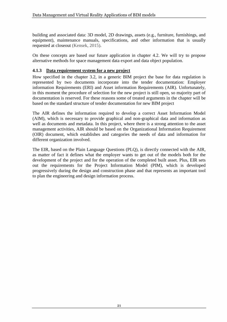
4.1.3 Data requirement system for a new project
How specified in the chapter 3.2, in a generic BIM project the base for data regulation is
represented by two documents incorporate into the tender documentation: Employer
information Requirements (ERI) and Asset information Requirements (AIR). Unfortunately,
in this moment the procedure of selection for the new project is still open, so majority part of
documentation is reserved. For these reasons some of treated arguments in the chapter will be
based on the standard structure of tender documentation for new BIM project
The AIR defines the information required to develop a correct Asset Information Model
(AIM), which is necessary to provide graphical and non-graphical data and information as
well as documents and metadata. In this project, where there is a strong attention to the asset
management activities, AIR should be based on the Organizational Information Requirement
(OIR) document, which establishes and categories the needs of data and information for
different organization involved.
The EIR, based on the Plain Language Questions (PLQ), is directly connected with the AIR,
as matter of fact it defines what the employer wants to get out of the models both for the
development of the project and for the operation of the completed built asset. Plus, EIR sets
out the requirements for the Project Information Model (PIM), which is developed
progressively during the design and construction phase and that represents an important tool
to plan the engineering and design information process.

Data Management and Virtual Reality Applications of BIM models
22
Figure 5: Relationship between elements of information management (BSI, 2014)
Based on this methodology the customer, Ente Ospedaliero Ospedali Galliera (EOOG), has
decided to divide the whole project in 40 categories based on construction technology. This
partition permits to organize and simplify the workflow, to better understand customer
requests. For each category is specify the value of LOD (Level of Detail) and LOI (Level of
Information) in all construction phases (Definitive, Executive and Realization phase), plus
one more level related to the phase of delivery and handover of the project. Of course, the
requirement, related to LOD and LOI, increases during the project development, and it is
evident from this estimate the importance of the management aspect for the customer. The
higher level, in fact, is set up for the last phase when the model will be transmitted and use for
management and maintenance of the building by the technical office of the hospital.
The AIR-02 also contains indication for IFC and COBie classifications of data stored into the
model. In each category is indicated the IFC classification to use for the relative elements and
if the category requires the COBie format, which fulfil an important aspect into the whole
project. From the beginning, in fact, COBie knowledges were represented as fundamental
request for the information management in the tender evaluation because the building model
will be based on this type of data for Facility Management aims.
In according with the objectives of EIR documents, it is also interesting the choice to use pre-
set parameters for the model development (using a file of shared parameters), integrating
them in the entire process. For EOOG to set up additional parameters into the digital model is
a fundamental aspect to have a correct parameters development along the whole process,
ensuring that the digital model will follow the guidelines necessary for future management
procedure.

Data Management and Virtual Reality Applications of BIM models
23
4.2 Methodology: Dynamo for Data Management
How said before Schedules are a great tool, present in Revit, which makes easier accessing
and sharing information especially for people who are not expert in using the software.
However, for complex project where we find a large amount of data, exporting and
individuating a specific information range it is not always an easy process. It is possible find
on the market several plug-in or applications which allow to make easier the export/import
process from/into the model, but usually they don’t give freedom of changes, keeping model
and schedules settings. As a matter of fact, schedules are separated for different category
(Rooms, Walls, Windows, etc.), this make more complicate to combine information or to
select only a particular parameter for the different categories without to analyze a big number
of data. In the next chapters we aim, in the first two applications, to develop a process that
allows inexpert and professional people to select and combine different parameters from
different category. In the third application we will show a method for family data population.
To develop all applications, Revit, Dynamo and Dynamo player have been used.
4.2.1 Identification of target and data
The first step, to develop a digital methodology for data management, was to understand
which kind data analyze, starting from the target of people that will use them. In our case the
building is represented by a hospital, for this we have defined three different groups of users:
• Visitors and Patients: they represent the majority part of people present in a
hospital and at the same time who needs more information to understand the
complexity of the structure. For this group is essential ensuring an ease access
for all building information and a clear language of communication.
Principally the kind of data to use for visitor and patience are spatial
information related with the hospital distribution of sectors, department, etc.
Knowing the distributive aspects of the building is an important point for
general user to understand how to move inside the building and to know all
the safety aspects necessary for a public building.
• Medical staff: also, for this group spatial information are essential, however
unlike the previous one they are experienced about the building distribution.
For this the main information essential for medical staff are focused on the
room destination and room services. They need to know all the features of
each room, starting from the functionality of the local until the medical
equipment parameters.
• Technical staff: with this group we mean all the people responsible for the
building maintenance and management. It is easy to understand that in this
case the information range cannot be limited to certain aspects, but it covers
the whole building project. Also, the kind of information language is different
from the previous two groups, requiring more technical specification. Data,
essential for this group, are of space management, object information,
structural properties, plant disposition, and parameters of this type.
4.2.2 Dynamo
Dynamo is a visual programming tool which can be downloaded as free and it gives users the
possibility to script using several textual programming languages through visually script code

Data Management and Virtual Reality Applications of BIM models
24
blocks. This allows both non-programmers and programmers people to manipulate element,
data and geometry in Revit by coupling script nodes which are previously programmed to do
a specific task. The language used to write the codes is Python and each node has a simple or
a complex script depending on the operation that it must conduct. Most nodes in dynamo are
composed of five parts, how see in Figure 6:
1. Name of the node;
2. The main body of the Node. Right-clicking here presents options at the level of the
whole Node;
3. The in and out ports. The receptors for Wires that supply the input data to the Node as
well as the results of the Node's action;
4. Lacing Icon. Indicates the Lacing option specified for matching list inputs;
5. Default Value. Right-click on an input Port, some Nodes have default values that can
be used or not used.
Figure 6: Anatomy of a Node (Dynamo)
4.2.3 Dynamo for Export data – Application 1
In the first application we have used Dynamo to export information and parameters related to
space management application. Dynamo don’t put limit on what you can develop and there
are infinity ways to interact with Revit, our aim for this part is to develop a script and so a
process to extract Revit parameters from different Revit Categories combining them in the
same file. The main idea is to allow non-expert people on Revit software to have the ability to
select a project section and to choose the information that they want to analyze, and at the
same time specialist can use this method to classify and to organize information making easier
sharing process. The script explained below permits to extract parameters, chosen by the user,
from all Revit Category presented into the model selecting first the floor to analyze.
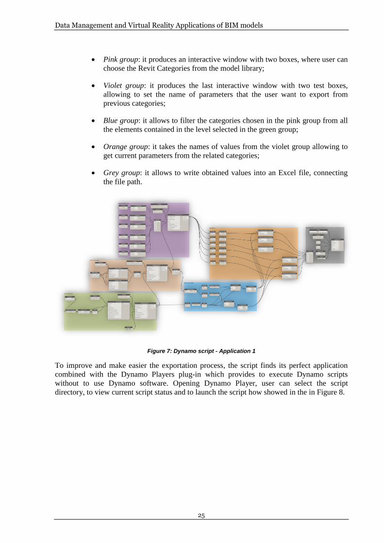
In the following picture (Figure 7) we see the whole script composed from the different nodes
and groups. For more details see Appendix 1. Shown below the different task for each group:
• Green group: it allows to produce an interactive window with the list of Revit
model levels, giving the ability to select the floor to analyze;
Data Management and Virtual Reality Applications of BIM models
25
• Pink group: it produces an interactive window with two boxes, where user can
choose the Revit Categories from the model library;
• Violet group: it produces the last interactive window with two test boxes,
allowing to set the name of parameters that the user want to export from
previous categories;
• Blue group: it allows to filter the categories chosen in the pink group from all
the elements contained in the level selected in the green group;
• Orange group: it takes the names of values from the violet group allowing to
get current parameters from the related categories;
• Grey group: it allows to write obtained values into an Excel file, connecting
the file path.
Figure 7: Dynamo script - Application 1
To improve and make easier the exportation process, the script finds its perfect application
combined with the Dynamo Players plug-in which provides to execute Dynamo scripts
without to use Dynamo software. Opening Dynamo Player, user can select the script
directory, to view current script status and to launch the script how showed in the in Figure 8.

Data Management and Virtual Reality Applications of BIM models
26
Figure 8: Dynamo Player (Dynamo)
Using this process, a general user needs only to open the Revit file and to launch the script.
This can avoid interacting with Revit Schedules setting each parameter and exporting
different files for each category. Of course, this cannot substitute the benefit to use Schedules,
but in huge project it can make faster selection of a range of information. For this example,
the script is set up to analyze only two Categories and three parameters for each category (six
in total), but it can be enhancing without objective limits adding other nodes of the same type
and ensuring a solid structure to the script. In fact, another positive aspect it also represented
from the ability to improve and personalize the process as you prefer for your purpose
changing the Dynamo script, aspect which is not always possible with external plug-in and
tools.
4.2.4 Dynamo for Export data – Application 2
This second application is always related with the exporting process from Revit, but while the
previous one analyzed the whole Level this one will focus the attention only on a single
Room. The aim of this part is to develop a script and so a process to extract all elements
contained in a single room, chosen from the user, combining all information in a single file.
The main purpose of this application is to give an easy way for non-expert user to access at
data located into a room, making easy the process of maintenance and control, and for expert
and specialist people to have an easy method to select and classify information.
In the following picture (Figure 9) we see the whole script composed from the different nodes
and groups. For more details see Appendix 2. Shown below the different task for each group:

Data Management and Virtual Reality Applications of BIM models
27
• Green group: it allows to produce an interactive window with a list of all
rooms presents into the whole Revit model, giving the ability to select one of
these;
• Orange group: it takes the names of the room selected in the previous group,
verifying which elements of the pre-set categories are present into the room;
• Blue Group: it is needed to sort the several values in a correct list to be
overwrite in an excel file;
• Grey Group: it allows to write obtained values into an Excel file, connecting
the file path.
Figure 9: Dynamo script – Application 2
As the previous one this script finds the perfect application integrated with the Dynamo
Player use. How mentioned above with this tool the users have the ability to see the family
located into a room obtaining the Family Name and the Family Type of each element. In this
example the Category of Families, to find into the room, are pre-set, but there isn’t limitation
on the number of Families to pre-set. In our case, for example, five Families are set to check if
they are located into the room and they are: Doors, Windows, Furniture, Electrical Equipment
and MEP Fabrication Containment. Also, here the script can be improved and adapted for
each necessity, allowing professional and non-professional to export values for a specific
room useful both to combine data in a simple way and for maintenance aims.
4.2.5 Dynamo for Export/Import data – Application 3
The last application aspires to find an easy method for data family population. Differently
from the previous two, this is divided in two Dynamo scripts because one has the aim to
export values from Revit to Excel while the second one is necessary to re-import values from
Excel to Revit. Using this process, the user can select one or more elements from the Revit
model exporting their data in Excel where everyone can set values for several family-
parameters and then import these changes into the Model.
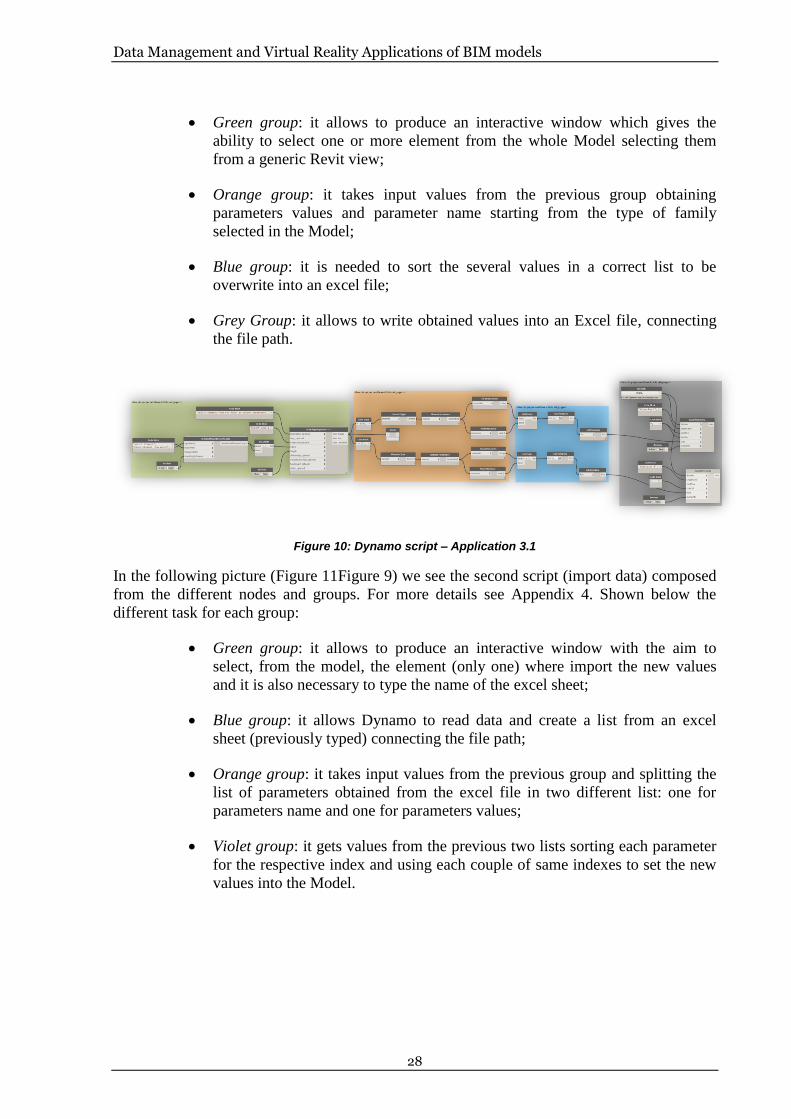
In the following picture (Figure 10Figure 9) we see the first script (export data) composed
from the different nodes and groups. For more details see Appendix 3. Shown below the
different task for each group:
Data Management and Virtual Reality Applications of BIM models
28
• Green group: it allows to produce an interactive window which gives the
ability to select one or more element from the whole Model selecting them
from a generic Revit view;
• Orange group: it takes input values from the previous group obtaining
parameters values and parameter name starting from the type of family
selected in the Model;
• Blue group: it is needed to sort the several values in a correct list to be
overwrite into an excel file;
• Grey Group: it allows to write obtained values into an Excel file, connecting
the file path.
Figure 10: Dynamo script – Application 3.1
In the following picture (Figure 11Figure 9) we see the second script (import data) composed
from the different nodes and groups. For more details see Appendix 4. Shown below the
different task for each group:
• Green group: it allows to produce an interactive window with the aim to
select, from the model, the element (only one) where import the new values
and it is also necessary to type the name of the excel sheet;
• Blue group: it allows Dynamo to read data and create a list from an excel
sheet (previously typed) connecting the file path;
• Orange group: it takes input values from the previous group and splitting the
list of parameters obtained from the excel file in two different list: one for
parameters name and one for parameters values;
• Violet group: it gets values from the previous two lists sorting each parameter
for the respective index and using each couple of same indexes to set the new
values into the Model.

Data Management and Virtual Reality Applications of BIM models
29
Figure 11: Dynamo script – Application 3.2
Also, for this case using Dynamo Player, the process will result faster and easier to use. How
explained these two scripts should help the process of data population for elements located
into the model, making easier the compiling process. With the script 3.1 each user can export
Type Parameters (and no Instance Parameters) from the model, just selecting one or more
element from a Revit view, into an excel file with separated sheets for each selection where
one column is for the name of the parameter and one column is for the value. Of course, the
process can be adapted also for different kind of parameters but for simplicity we have chosen
Type Parameters because Instance Parameters, for example, are not modifiable in majority
part since depending by the geometry and features of the Family.
For our example the number of element to select is limited at two, but the number can be
augmented using the same script structure. After to have filled the excel file, inserting new
values, they can be re-imported into the Model through the second script (script 3.2). For this
part, in order that the process can works properly, is important to type exactly the name of the
excel sheet and to select the related element with the values of the sheet. In the Figure 12 we
can see an example of this process applying it for a flor family, the image on the right is the
empty Identity Data list before to apply the scripts and the image on the left is the list after the
process.

Data Management and Virtual Reality Applications of BIM models
30
Figure 12: Application 3 – Example
The process is limited by the nature of some parameters. Grey parameters showed in the
Figure 12 are values which cannot be altered using excel because they are defined within the
family. Other as “Type Image” parameter need different information format, in this case is a
graphic format, that importation process don´t allow to set.
It is clear that Revit gives the ability to type values directly from the model, but this means to
type for, each different element, each value and of course the user must have knowledges of
the software. On the other hand, using the workflow presented in this chapter it is possible to
export the parameters of all families at one time and for project with hundreds of different
elements, it is a great advantage, plus everyone can fulfil the task simply using excel.
4.3 Results
With this chapter we have brought the attention on the importance of data in a correct Facility
Management context, related on our study case and with our target of users. Building these
work processes, in fact, we aim to improve the sharing information for all figures involved in
the process, professional and non-professional. The main idea is to use these methods as base
for future developments, showing the possibilities to set up an interactive data management
method using Dynamo software. Starting from this workflow the possible applications are
unlimited, especially for complex structure like a hospital where is present a huge number of
data, so not restricting the Dynamo use at space management application. In the last years, in
fact, it has become an essential tool for innumerable aspects with two essential strong points:
to allow interacting in a complete way with Revit and the freedom of application limited only
by user knowledges.

Data Management and Virtual Reality Applications of BIM models
31
This methodology will be also connected with the following chapter, providing the essential
data to visualize in the virtual environment.

Data Management and Virtual Reality Applications of BIM models
32
5 VR for Architectural visualization
How said in the previous pages the advantages of BIM methodology are many, from the
easier storage of all data into the model until the easy way to cover each phase of the
construction process. BIM represent also a revolution in this sector for the new way to design
and think the project, based on a 3D environment. This aspect obviously helps professional
people to have a clearer idea about the project in each construction phase, but having software
based on 3D data a lot of new technologies approach to AEC industry. In this context new
visualization methods become main characters on the utilizing process of 3D data, and one of
the method is based on the Virtual Reality (VR) technology.
In the next page we will introduce the concept of VR, seeing how it can be useful for
construction sector and presenting an example based on our study case.
5.1 VR application for AEC industry
The VR (Virtual Reality) technology is a computer simulation to create an environment like
the real life, where the user can interact with this environment through some input like a
movement of a hand or a vocal command; this means that the computer can recognize the
input and to create an answer in real time. This technology is based on a real-time rendering
which (differently of the traditional 3D rendering where 3D-data are converted to pixels in a
2D image) is a process that running continuously. To give to the user the impression to travel
around in a virtual word, computer must generate a sufficient number of frames per second to
prevent the user from experiencing motion sickness (Hettinger, 1992).
The result of the real-time rendering can be displayed in a wide variety of ways. The most
common solution for a virtual experience is wearing a head-mounted display (HMD), which
allow the user to involve more sense (touch, eyesight, hearing, etc.) with different levels of
immersion. Nowadays the most common devices, for an immersive VR experience, presents
on the market are Oculus Rift, HTC Vive and Gear VR. The first two are directly linked with
the computer and while the first one has any controllers, but you need to use a mouse,
keyboard or a joystick, the second one is used with wireless sensors and controllers able to
control the movement and send them to the computer. The Gear VR are simpler and cheaper
and for this more popular. The substantial different with the previous two are that the images,
data and the virtual environmental are all elaborate from a smartphone without to use a
computer. Other interesting alternatives, but less ordinary, are the CAVE and the Powerwall.
The first uses LCD shutter glasses to have a stereoscopic vision with a method that allows to
render an image for each eye sequentially and this switching process is synchronized with the
graphics card and performed at a high frequency; the second one is a semi-immersive and it is
basically a small cinema screen allowing more people to view the VR simulation
simultaneously with shutter glasses or polarized glasses (Johansson, 2016).

Data Management and Virtual Reality Applications of BIM models
33
Figure 13: Example of VR use with BIM model
Behind this word we find a lot of software used to create three-dimensional simulations. The
most famous and powerful in this moment are software based on game engine environment,
generally used to develop video-games and the biggest exponents (related with AEC
applications) are: Unity, Unreal, Stingray and Cryengine. They allow users to have freedom
of development the virtual environment, limited only by software knowledge and
programming language. Not being designed for AEC applications, sometime to use game-
engine software can represent not an easy method. The mains problems, in fact; are correlated
with the interoperability aspects between these software with common design software,
causing information losses during transfer process. To simplify this process of virtual
environment creation several tools are present in the market, which can be used as plug-in for
design software. The advantage in this case is represented by the ease method to get the
virtual simulation of your project, launching it directly from your project browser and without
to interact with other software. The most common software, of this type, are: Enscape, IrisVR,
Autodesk LIVE and Fuzor. On the other hand, they present several limitations to personalize
and develop your virtual environment respect the previous game engine software. These tools
don’t allow, in fact, interacting with the creation process limiting the result on a tree-
dimensional environment where the user can only go around.
For these reasons in the following pages we will show a workflow example of how develop a
virtual environment using Unity software, providing a basis method useful to understand
which potentialities it has related with AEC industry. In our case the starting point is
represented from a small part of the Revit project of the Galliera Hospital and particularly by
one of the main entrance.
5.2 Methodology: From Revit to Unity
For our aims the first step to develop a virtual environment starting from a BIM model, and in
this case from a Revit model, selecting the portion of model that we want to analyze
simplifying the model. We have chosen to delete all unnecessary information that Unity

Data Management and Virtual Reality Applications of BIM models
34
cannot read, as annotation elements or linked file, keeping the essential building geometry to
create the environment.
To start the process of transfer, Revit file has been exported as “.fbx format file”, which
ensure to have a good level of interoperability between modelling software, keeping all
necessary 3D data as material textures and elements properties. Intermediate software must be
used between Revit and Unity to allow that all elements in the model can have the correct
standardization to unsure a good quality of the final product. Unity, in fact, cannot read
standards of Revit material library, making problematic a direct transfer. For all this reason
the 3D Studio Max software has been used.
Figure 14: Revit – Unity interoperability process
The process starts exporting the Revit model in “.fbx” format, from the Revit menu through
the following step: R menu > Export > FBX. It is important that the model is on a 3D view.
After opening 3DS Max is necessary go on the general menu section to import the previous
extracted file and click on Import > Link FBX. At this point we have to set correct parameters
of import using the window that automatically appear. In this case we have chosen” Combine
by Revit Material” option, including in one group all elements based on the same material
(Figure 15).

Data Management and Virtual Reality Applications of BIM models
35
Figure 15: Export/Import “.fbx” format file
After this procedure 3DS Max allows to manage all elements and materials present into the
model converting them to standard materials. Now it is possible to choose different way to
continue, depending on the outcome and quality to reach. Using the software, in fact, you can
change the render quality of each material and change each propriety, but for our case we
have preferred to focus only on the method and to don’t care about graphic quality. For this
we have simply converted the material through selecting “Rendering>Scene converter” and
then export the file from the 3DS Max menu how showed in Figure 16.
Figure 16: Export process from 3DS Max
At this point the model is ready to be imported in Unity and in the following chapter we will
analyze the correct method to obtain a virtual environment.

Data Management and Virtual Reality Applications of BIM models
36
5.3 Unity Workflow
As already mentioned Unity is a cross-platform game engine used to develop three
dimensional and two-dimensional video games and simulation for computer, console and
mobile device through geometrical modelling and coding. Unity is structured to facilitate the
files management, the whole project, in fact, is stored in a single folder on your hard disk,
where there are a wide variety of folders and files, which are mostly regulated in background
by Unity. In particular the Assets folder is where all files are stored that you need to manage
directly, such as model, script, textures and scene files (Boeykens, 2013). Before to start with
the description of the whole workflow explain the structure of Unity is important, recapping
the main parts (Figure 17).
Figure 17: Unity structure (Boeykens, 2013)
A Unity project is structured by Scene, and each scene will compose the whole game, as is
common for virtual game. Each scene is developed separately from others and this process
take place within the main Unity interface, which is divided in the following parts:
• The main part is represented from the Scene Tab where the user can manage the
geometry of the model in a 3D or 2D view;
• The Hierarchy Tab displays elements of the current view that can be also used a main
menu to select each element present into the scene;
• Inspector Tab allows seeing and managing all the properties of any selected object.
• Project Tab manages all the assets folder present in the project and from here the user
can access at each element and to load news object;

Data Management and Virtual Reality Applications of BIM models
37
• Game Tab represent a preview of how the scene will look when you play the game,
but without the possibility to walk, to do this is necessary to press the Play button.
All these definitions will be essential for the next chapters, and then it is important to know
that, how other game engine software, Unity is regulated by a scripting language and each
user can develop the game through three different coding: C#, JavaScript and Boo.
5.3.1 Virtual Environment Develop
The model obtained from the previous process is loaded first in the System Assets folder and
then in the Hierarchy Tab. From the Inspector Tab is important to select the “Generate
Colliders” option, to ensure that all elements present in the model will have a solid geometry
necessary for a correct navigation (image 1-Figure 18). Next step is to select from the Game
Object menu > Light > Directional Light, inserting a center of light to have not a dark virtual
environment (image 2-Figure 18). The last step is to import the specific “player” to can walk
freely around the model. To do this we have to import from the Asset Store the adapt package
importing the whole folder inside the project. The correct procedure is the following: Asset
menu > Import Package > Character control > First Person Controller (image 3-Figure 18);
after it is enough to load the First-Person Controller icon into the Hierarchy Tab.
Figure 18: Essential Step to Create a Virtual Environment
At this point the model is theoretically ready to be navigable. To obtain a more realistic
experience, through the virtual environment, we have chosen to insert other element as trees,
the terrain and the sky. All these passages have done importing the related package as “Tree
Creator”, “Terrain Assets” and “SkyBoxes”, plus some textures have been changed directly
into Unity because during the transfer some of them have been lost. In this way it was
possible recreate a more realistic simulation (Figure 19).

Data Management and Virtual Reality Applications of BIM models
38
Figure 19: Unity Model interface
In the next chapter we will see how create a simple example of game from the model, to be
shared and used from several stakeholder. To launch this game example, in fact, is not
necessary to have installed Unity in your device.
5.3.2 Standalone game creation
Unity makes available several ways to build a game from your model. All these options are
present into the File menu > Build settings (Figure 20-left). From this window, in fact, user
can create for example a platform for Smartphone (Android, iOS, etc.), video game console
(Xbox and PlayStation) and standalone files usable from computer. For our case, where the
aim is to provide an example of VR application and its potentiality in AEC industry, we have
chosen to develop only a game example using the PC Standalone option (Figure 20-right).
There is also the opportunity to use the “Web Player” option, which allows creating a
platform available from web. However, this option sometimes brings problem of
interoperability with some of the most common browsers as Google Chrome. Through the
option that we have chosen, Unity allows creating an independent folder with the “.exe” game
file and all data necessary to launch the simulation, selecting only the kind of platform and
where to save the new folder. At this point we have a folder with our game example, which
can be sent and used by all people want to explore the project.

Data Management and Virtual Reality Applications of BIM models
39
Figure 20: Standalone File Creation
To start the simulation is enough to launch the “.exe” file format and set up the features of the
simulation (Screen resolution, Graphic quality and Select monitor), through the interactive
window that automatically appear. After this, a temporary Unity interface will be open and
then the user will be teleported into the model, using mouse and keyboard he will be able to
walk around and inside the model (Figure 21).
Figure 21: Unity Walkthrough

Data Management and Virtual Reality Applications of BIM models
40
In the next chapter we will continue to improve our virtual simulation, adding data
information into the model and making more interactive the walkthrough.
5.3.3 Data Visualization
This part aims to connect the data management section, of the current report, with the current
chapter. To do this data sheets will be imported into the Unity model, allowing users to have
not only a three-dimensional experience but also to access to building data during the
simulation. The interaction between game player and data will be automatically. Particularly
when the player will be enough close to one object, which has been set to have information, a
data sheet will appear to consult it.
The process starts creating a general object (in this case a cube) through the sequence: Game
Object menu > 3D Object > Cube. After, selecting the element just inserted, from the
Inspector Tab is essential to select the option “Is Trigger”, from the “Box Collider” section.
This last selection will allow the object to understand when the player is close enough. Both
the procedures have been showed in Figure 22. This element will be the point of reference to
insert the data documents.
Figure 22: Cube Game Object
The second step is to load an interactive image that can appear during the simulation and can
follow the movement of the player camera. From the Game Object menu is present an
element with these features and it is available to: Game Object > UI > Image. Automatically
in the Hierarchy Tab a “UI Canvas” will be loaded together at the image element. Selecting
the “Image” option in Hierarchy Tab any graphic file can be load from the Inspector Tab. At
this point it is important to place in the correct position the image respect to the cube,
ensuring the same origin point.
The third part provides for the creation of a C# script to connect the first object with the
loaded image, and to ensure that with user movement the sheet can appear and disappear. This
is possible through the following process: Asset menu > Create > C# Script. Now; a new C#
file will appear on the Standard Assets folder and with a double click it can be compile with
MonoDevelop software or similar. The following Figure 23 shows the main point of the
workflow.

Data Management and Virtual Reality Applications of BIM models
41
Figure 23: C# script in Unity
How expressed into the script, only elements with the “Player” tag can be recognized from the
object with the “Trigger” option. For this, selecting our First-Person Controller, in the
Inspector Tab (under the object name) we have to set up the voice “Player” in the Tag menu
(image 1-Figure 24).
Now the process is almost ready to work, the last phase, in fact, is to connect all these several
elements. The starting point is to add the script on the cube previously set and the faster way
to do this, it is dragging the icon code into the Inspector Tab of the cube. Always in the same
script menu, in the “Custom Image” option, we have to drag the Image element from the
Hierarchy Tab to ensure the connection between both (image 2-Figure 24). The last step is to
make invisible the cube (during the whole visualization) and the image of the document while
the player is not close to the object (image 3-Figure 24).
Figure 24: Final steps Data Visualization
After all these processes the document has the correct proprieties to interact with the player
during the simulation. Now the virtual environment is ready to be explored with the
opportunity to consult and read data, related with the building.

Data Management and Virtual Reality Applications of BIM models
42
Figure 25: Unity Walkthrough Data Visualization
5.4 Result
This chapter have showed how a Virtual Simulation of our building project can be create,
starting from a Revit model. It goes without says that the applications of this methodology are
almost unlimited in the AEC sector, bringing benefits for all phases and sectors of a
construction process. In our case, for example, we have chosen to develop the simulation
loading data got from the Data Management chapter. In this way during the virtual
exploration a general user can access to the main information of the floor where he is located,
otherwise a professional going into a room can visualize all features and parameters of
specific object.
How saw in some part of the process there are some methodology limitations yet,
interoperability problems or problematic procedures that makes the technology not easily
accessible. But this represents a normal aspect for a technology that only on the last years has
seen a continuous development. On the other hand, the building sector cannot ignore how
important Virtual Reality is becoming for all construction and design phases, solving
problems that always have been the weak point of the AEC industry.

Data Management and Virtual Reality Applications of BIM models
43
6 Conclusion
We have seen that construction industry is inside a period of strong changes, many new
technologies start to be essential and new regulations govern the sector structure. Always
more people are involved during each construction phase, to ensure a high efficiency during
the whole building lifecycle, but at the same time complicating significantly the management
project aspect. These and other problems are highlighted when we talk of healthcare
structures, where the growing complexity of design and the huge number of data represent a
difficult challenge for all stakeholders. In this framework new methodologies are necessary,
and BIM is the leader, allowing to make more efficient the construction process.
However, functionally workflow is essential, particularly when we talk of data management.
We saw how important the role of data is to storage and share information, but also
complicated and not always accessible for everyone. Setting up a data structure, based on the
ease of use and simplicity to understand, represents the key point for a great Facility
Management method. Following this concept, we have tried to develop a solution to promote
information sharing, both for professional and non-professional subject, making faster data
population and consultation from a Revit model. Through Dynamo applications, in fact, we
aimed to provide a possible management method which can be a base for future development,
showing how powerful the computational design software is.
At the same time, to cover the communication gap between different involved actors, Virtual
Reality represents a great solution. Integrating it in an efficient workflow, many problems of
misunderstanding can be solved saving money and time. For this we have chosen to connect
information management with real-time visualization, because both are two side of the same
coin. 3D data, in fact, can bring a strong improvement in the whole sector, changing the same
concept of construction that now we have. Nowadays new technologies make more available
this methodology and, how we showed, to create a virtual simulation becomes always easier.
This work wants to provide an overview about where the construction industry is going,
displaying potentiality of new work methodologies applied to an important project example.
The main purpose, in fact, was to develop a method which could explain the deep change of
the sector, showing how to integrate new technologies in a construction workflow. Following
this idea, the thesis aims to produce a methodology that could be a starting point for future
application based on sharing information and real-time visualization.

Data Management and Virtual Reality Applications of BIM models
44
Reference
Boeykens, S. (2013). Unity for Architectural Visualization. Birmingham, UK.
Bouchlaghem, D. S. (2005). Visualisation in architecture, engineering and construction (AEC).
BSI, B. S. (2014). PAS 1192-3:2014 - Specification for information management for the operational
phase of assets using building information modelling. London: BSI Standards Limited .
buildingSMART. (2018). IFC Intruduction. Retrieved 04 29, 2018, from buldingsmart:
https://www.buildingsmart.org/about/what-is-openbim/ifc-introduction/
Collinge, W. (2012). The role of the design artefact in hospital briefing and design works.
Cooney, J. (2012). Cooney, The use of building information modelling (BIM) with healthcare.
Dynamo. (n.d.). The Anatomy of a Visula Program . Retrieved from Dyanomopremier:
http://dynamoprimer.com/en/03_Anatomy-of-a-Dynamo-Definition/3-
1_dynamo_nodes.html
Eastman, C. T. (2008). Chapter 12: BIM for Owners and Facility Managers. In In BIM Handbook: A
Guide to Building Information Modeling for Owners, Managers, Designers,Engineers, and
Contractors (pp. 93-147). New Jersey: John Wiley & Sons: Hoboken.
Eastman, C. T. (2011). BIM Handbook : A Guide to Building Information Modeling for Owners,
Managers, Designers, Engineers and Contractors. Hoboken, New Jersey.
FIEC. (2017). Making BIM a global success. Brussels.
Galliera, E. O. (2017). Disciplinare di Gara. Genova .
Galliera, E. O. (n.d.). www.galliera.it/immagini. Retrieved from www.galliera.it.
Hettinger, L. R. (1992). Visually induced motion sickness in virtual environments.
Iadanza E., T. B. (2015). The STREAMER European Project. Case Study: Careggi Hospital in
Florence.
Johansson M, R. M. (2014). From BIM to VR, Integrating immersive visualizations in the current
design process.
Johansson, M. (2016). From BIM to VR- The design and development of BIMXplorer . Gothenburg:
Chalmers University of Technology .
Kensek, K. (2015). BIM Guidelines Inform Facilities Management Databases: A Case Study over Time.
Buildings .

Data Management and Virtual Reality Applications of BIM models
45
Khanzode, A. F. (2008). Benefits and lessons learned of implementing building virtual design and
construction (VDC) technologies for coordination of mechanical, electrical, and plumbing
(MEP) systems on a large healthcare project. ITcon Vol.13, 324-342.
La Franca, G. (2016, May). Ospedali Galliera, Progettare la sostenibilità. Tecnica Ospedaliera, pp. 50-
56.
Manning, R. M. (2008). Case studies in BIM implementation for programming of healthcare facilities.
ITcon Vol.13 , 446-457.
Milgram, P. T. (1995). Augmented reality: a class of dislays on the reality-virtuality continuum.
Mohammadpour, A. A. (2017). Retrofitting of healthcare facilities: case study approach.
Okada R.C., S. A. (2017). Owner-requested changes in the design and construction of government
healthcare facilities.
Osello, A. U. (2017). BIM: verso Il catasto del futuro. Turin.
Poljanšek, M. (2017). Building Information Modelling (BIM) standardization. Joint Research Centre
(JRC).
Spallarossa, E. (2016, June). Bim for Italian Public Employers - Galliera Genoa Hospital Example .
Solibri Journal, pp. 40-42.
Ugliotti, F. (2017). BIM and Facility Management for smart data management and visualization.
Torino: Politecnico di Torino.
University of Waterloo. (2017, January 5). New Karolinska Hospital - Future of Construction.
Retrieved from Future of Construction.
Word Economic Forum. (2016). Shaping the Future of Construction: Future of Construction: A
Breakthrough in Mindset and Technology. Geneva, Switzerland.

Data Management and Virtual Reality Applications of BIM models
46
Appendix 1
In this appendix we will analyze more thoroughly the Dynamo script Application 1
Figure 7: Dynamo script - Application 1
Green Group
Figure 26: Dynamo script – Application 1.1
The core of this group is represented by the script “UI.MultipleInputForm +”, which allow to create
an interactive widows starting from several inputs. The aim is to create a tool to choose the level of my
building for this we have used “UI.Listview Data”, which allow creating a window with a list of all
input elements. In our case the inputs are all the levels present into the Revit model. Important is the
“Boolean” node to ensure that the node works. To allow that the process continues running we have
connected the output “was run” with the following group.
Pink Group

Data Management and Virtual Reality Applications of BIM models
47
Figure 27: Dynamo script – Application 1.2
This group is based on the same node of the previous on. The aim of this one is to create a window
where the user can select the Revit Category to analyze form the previous selected level. The node
“UI.DropDown Data” gives the ability to create a task bar to write a string. For this example, only two
task bars are set up but there isn’t a limit of number to insert. With more selection input is necessary
use the node “List.Create” two keep split the values. In this case a Python script node has been
necessary to translate the input categories from a string to a Revit element. Here the python script: import clr clr.AddReference("RevitAPI") import Autodesk from Autodesk.Revit.DB import * cat = UnwrapElement(IN[0]) names = [] for c in cat: names.append( c.Name ) OUT = names
To allow that the process continues running we have connected the output “was run” with the
following group.
Violet Group
Figure 28: Dynamo script – Application 1.3

Data Management and Virtual Reality Applications of BIM models
48
Also, in this case we have used the ““UI.MultipleInputForm +” to create the last interactive window,
where the user can write the name of the parameters to export. To do this we have used the node
“UI.TextBox Data”, which creates a box where typing the input parameter. In this example only 3
parameters for each category chosen in the previous group has been set up, but there isn’t a limit of
number to insert.
Blue Group
Figure 29: Dynamo script - Application 1.4
This group aims to filter selections of the pink group from the green group. We the green group, in
fact, we have selected the level of our interest but from it we want to extract only the information
about the categories selected in the pink group that are present in the current floor. To make possible
this we have used the nodes “List.ContainsItem” and “List.FilterByBoolMask”. The first one needs to
compare all element of the level with all elements of categories, producing a boolean value (true/false)
for the elements that have been matched and for those haven’t. After this the second one node read the
boolean value for each element making a list with the “true” elements if you select the “in” output or
with the “false” element if you selected the “out” output.
Orange Group

Data Management and Virtual Reality Applications of BIM models
49
Figure 30: Dynamo script - Appllication 1.5
This Group connects the previous groups with the name of the six parameters from the violet group. In
the first part we have split, from the violet group, the name of each parameter through a simple code
block selection node and then they have been converted in strings. After this we have used the
“Element. GetParameterValueByName” to extract the value of the parameter from the Revit model
and to write it on an excel file.
Grey Group

Data Management and Virtual Reality Applications of BIM models
50
Figure 31: Dynamo script – Application 1.6
The last one group allows to write the data from the model in an excel file. First of all, we have
created a list with the node “List.Create” to put together the previous values and then we have used the
node “List.Transpose” to invert rows and colons. After this we have used “Excel.WriteToFile” with all
the inputs showed in the picture above.

Data Management and Virtual Reality Applications of BIM models
51
Appendix 2
In this appendix we will analyze more thoroughly the Dynamo script Application 2
Figure 9: Dynamo script – Application 2
Green Group
Figure 32: Dynamo script – Application 2.1
For this Group we have used basically the same methodology used for the Green group in the
Appendix 1. The main difference is one input values, where this time they are set on the name of the
rooms that there are in the whole project. The purpose of this group is to give the possibility to select
each room with an interactive window.
Orange Group This group aims to identify the elements that are present inside the chosen room. To make this
possible we have pre-set which kind of family the script has to check using the nodes “Category” and
“All Element of category”. In this example we have analyzed only 5 categories of element but there
isn’t a limit of input number. Then we have used the “Elements in Room” node to check if there is that
kind of element inside the room. In the positive case we get the Family Name and the Family Type of
the element.
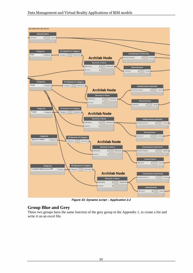
Data Management and Virtual Reality Applications of BIM models
52
Figure 33: Dynamo script – Application 2.2
Group Blue and Grey These two groups have the same function of the grey group in the Appendix 1, to create a list and
write it on an excel file.

Data Management and Virtual Reality Applications of BIM models
53
Figure 34: Dynamo script – Application 2.3

Data Management and Virtual Reality Applications of BIM models
54
Appendix 3
In this appendix we will analyze more thoroughly the Dynamo script Application 3
Figure 10: Dynamo script – Application 3.1
Green Group
Figure 35: Dynamo script – Application 3.1.1
For this Group we have used basically the same methodology used for the Green group in the
Appendix 1 and Appendix 2. The main difference is on input values, where this time we have used the
“UI.SelectModelElements Data” node to create an interactive window, to allow choosing, from the
model, elements to analyze. Creating a list after the previous node we can set the number of element to
select, only two for example.
Orange Group

Data Management and Virtual Reality Applications of BIM models
55
Figure 36: Dynamo script – Application 3.1.2
This group starts taking the outputs from the previous one, dividing them through a code block node.
Then we have used the “Element.Type” value to obtain the element Family Type and from this, using
the “Element.Parameters” node, we get the all Type parameters of current element. Then we have
needed to split the parameter between the parameter name and the parameter value, to can collect the
values in a different excel cell from the name.
Blue and Grey Group
Figure 37: Dynamo script – Application 3.1.3

Data Management and Virtual Reality Applications of BIM models
56
These two groups have the same function of the grey group in the Appendix 1and 2, to create a list and
write it on an excel file. In this case are present two “Excel.WriteToFile”( both are connected at the
same excel file) one for each selection in the first group.

Data Management and Virtual Reality Applications of BIM models
57
Appendix 4
In this appendix we will analyze more thoroughly the Dynamo script Application 4
Figure 11: Dynamo script – Application 3.2
Green Group
Figure 38: Dynamo script – Application 3.2.1
For this Group we have used basically the same methodology used for the Green group in the
Appendix 1, and 3. The main difference, also in this case, is on input values, where this time we have
used the “UI.TextBox Data” and “UI.SelectModelElements Data” nodes. These two nodes insert in the
interactive window a typing box (the first one) to write the name of the sheet to analyze, and a selectio
button to select from the digital model the element connected with the sheet values.
Blue Group

Data Management and Virtual Reality Applications of BIM models
58
Figure 39: Dynamo script – Application 3.2.2
Through this group the script can read the values of the selected sheet, connecting at the
“Excel.ReadFromFile” node the file path of excel file and the creating a list.
Orange Group
The aim of this group is to organize the data to be imported into the Revit model. The list previously
created, from the excel file, has sorted values in two difference group because in the Appendix 3
(orange group) we have split them in name parameter and name value. Now under the index 0 we can
find the name and under the index 1 we find the value. So, using the “List.GetItemAtIndex” node, we
can create to separated list, one for name and one for value. Plus, we have used the “Elements.Type”
node connected with the element selected in the first group, to have the type of element necessary for
the next group.
Figure 40: Dynamo script – Appllication 3.2.3

Data Management and Virtual Reality Applications of BIM models
59
Violet Group
Figure 41: Dynamo script – Application 3.2.4
This group is born from the inability to find an iterative method able to analyze and combine multiple
the set the new values into the model. The aim of this group, in fact, is to insert in the Revit model the
new values that come from the excel sheet. To do this we have used the
“Element.SetParameterByName” node, which has the limit to set up only one parameter for node. For
this reason with the code block nodes on the left we have separated each value and name from their
list. Proceeding in this way we find for the parameter name at “x[0]” in the first code block node, the
equivalent parameter value at “x[0]” in the second code block node. Using together these values, plus
the element type from the previous group, we have been able to import the new values in Revit model.
We have to note that the number of 40 items, in both the code block, have been chosen to be sure that
generally all the parameters of a family can be analyzed. Some family, in fact, can have less of 40
parameters and in this case, Dynamo will show the error message for the node without an input, but
the remaining parameters will be set up correctly.


TRITA -ABE-MBT-18351
www.kth.se