Data Logger User Manual - Ocean Sensor Systems
13
1 OSSI-012-015 Data Logger User Manual Introduction: The OSSI-012-015 Data Logger is designed to take synchronous samples from our wired and wireless sensors. It can also log Analog Voltages and Generic Serial Data. Synchronized Sampled Data is time tagged and stored on a SD memory card. The Memory Card is easily removed and can be read on any PC using a standard SD Memory Card Reader. The data may then be displayed and analyzed with the new version 3 OSSI Interface Program. Sample Data may also be streamed out to a PC using the RS232 port, Rs485 port, Bluetooth or the optional 1-watt RF modem. . Please see the data sheet available on our web site at www.oceansensorsystems.com for additional detailed information. Data Logger 1. Install the USB to Serial adapter here. Data logger PCB SD Memory Card 2 Battery Packs, 18V Input Power Plugs
Transcript of Data Logger User Manual - Ocean Sensor Systems
1
OSSI-012-015 Data Logger User Manual
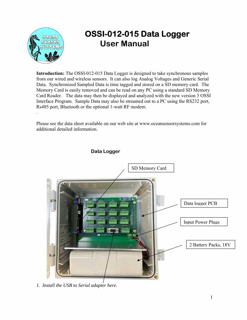
Introduction: The OSSI-012-015 Data Logger is designed to take synchronous samples from our wired and wireless sensors. It can also log Analog Voltages and Generic Serial Data. Synchronized Sampled Data is time tagged and stored on a SD memory card. The Memory Card is easily removed and can be read on any PC using a standard SD Memory Card Reader. The data may then be displayed and analyzed with the new version 3 OSSI Interface Program. Sample Data may also be streamed out to a PC using the RS232 port, Rs485 port, Bluetooth or the optional 1-watt RF modem. . Please see the data sheet available on our web site at www.oceansensorsystems.com for additional detailed information. Data Logger 1. Install the USB to Serial adapter here.
Data logger PCB
SD Memory Card
2 Battery Packs, 18V
Input Power Plugs

2
2. Download, from our web site, the OSSI Interface Program V3.0 and install it on a PC. 3. Connect the USB adapter to the PC and run the OSSI Interface Program. 4. Apply power to the Data Logger. 5. Set the Unit Type to Data Logger OSSI-012-015 and the Com Port A to the port with the USB adapter. 6. On the Configure Device Tab enter Device Number 255. 7. The Data Logger’s Configuration should now be displayed on the 3 configure tabs.

3
Connecting to the Data Logger’s Sensor Input Ports: RS232 Sensor Input #1 to #8: Used for Wave Staffs, Wave Staff IIIs, Wave Staff Synchronizers, Wave Staff RV-2s, Sonic Wave Sensor RV-2s and Generic RS232 Serial Data. Wiring, J5 to J12: Pin 1 B+ Source from Battery input voltage and current limited with 1 amp. fuse. Pin 2 +6V with 3 amp. Current limiting. Pin 3 TX RS232 Transmit output to sensor. Pin 4 RX RS232 Receive input from sensor. Pin 5 PGND Power ground (0 volt). Typical Wiring example, Wave Staff to RS232 port: Pin 1 B+ = no connection Pin 2 +6V = Wave Staff Red wire. Pin 3 TX = Wave Staff Green wire. Pin 4 RX = Wave Staff Orange wire. Pin 5 PGND = Wave Staff Black wire.
Pin 1

4
RS232 Sensor Input #1 to #8: Device numbers are automatically assigned to data.
Wave Staffs, Wave Staff IIIs, Wave Staff RVs, Sonic Wave Sensor RV and Generic Serial Data: RS232 #1 = Device #100 RS232 #2 = Device #106 RS232 #3 = Device #112 RS232 #4 = Device #118 RS232 #5 = Device #124 RS232 #6 = Device #130 RS232 #7 = Device #136 RS232 #7 = Device #142 Wave Staff Synchronizers: RS232 #1 = Device #100, #101, #102, #103, #104, and #105 RS232 #2 = Device #106, #107, #108, #109, #110, and #111 RS232 #3 = Device #112, #113, #114, #115, #116, and #117 RS232 #4 = Device #118, #119, #120, #121, #122, and #123 RS232 #5 = Device #124, #125, #126, #127, #128, and #129 RS232 #6 = Device #130, #131, #132, #133, #134, and #135 RS232 #7 = Device #136, #137, #138, #139, #140, and #141 RS232 #8 = Device #142, #143, #144, #145, #146, and #147

5
Analog Input #1 to #4: Programable ranges +/-10.24V to +/-0.64V and 10.24V to 1.28V Wiring, J1 to J4: Pin 1 B+ Source from Battery input voltage and current limited with 1 amp. fuse. Pin 2 +6V with 3 amp. Current limiting. Pin 3 +ANA is the + Analog input Pin 4 AGND is the Analog Common input, 0 volts. Pin 5 PGND is the Power Ground. Device numbers are automatically assigned to data.
Analog #1 = Device #201 Analog #2 = Device #202 Analog #3 = Device #203 Analog #4 = Device #204

6
RS485 Sensor Input #1 to #2: Auto Connect to Wave Staff RVs and Sonic Wave Sensor RVs. Wiring, J13 to J14: Pin 1 B+ Source from Battery input voltage and current limited with 1 amp. fuse. Pin 2 +6V with 3 amp. Current limiting. Pin 3 D+ RS485 + Transceiver line Pin 4 D- RS485 – Transceiver line Pin 5 PGND Power ground (0 volt) Device number must be preset from 1 to 99 by connecting the device separately to the OSSI Interface Program.

7
XBee/XBee Pro Wireless Sensor Input: Auto connect to Wave Staff XBs and Sonic Wave Sensors with same PAN ID. Device number must be preset from 1 to 99 by connecting the device separately to the OSSI Interface Program.
XBee Transceiver

8
8. Select the Configure Data Logger tab and set up the sensor port types etc. Example sensor port configuration: 9. On the Streaming Data Out section switch on the serial port connected to the PC.

9
10. The Streaming output will now be displayed on the Monitoring section. Example Output Monitoring: The streaming sensor data may now be plotted and analyzed etc.

10
Operating Power: The operating power may be read with the following steps. 11. Select the Configure Data Logger Cont. tab. 12. Enter 255 again to update the voltage and Current values. The displayed battery life is based on two 18V 12C cell packs. Each pack has a typical capacity of 140 Whrs totaling 289 Whrs. Battery life hours (for continuous operation) = 280 / watts. Example: When only wireless XB sensors are used, the battery life is typical 45 days. For longer operating days we recommend using an external power source like the following: Remote Power System OSSI-596-003: 2.5W Continuous Remote Power System. 10W integrated Solar Panel. Die Cast Aluminum Enclosure. 12V 9Ah Battery Tycon Systems RPDC12-9-10 The Data Logger power input voltage range is 8VDC to 36VDC. Either or both connectors may be used. They are Reverse Polarity Protection and Smart Diode Ored.

11
Logging Sensor Data on the SD memory card. Data may be logged on the SD memory card with or without streaming data out. Use the SD memory card supplied with the Data Logger or any other SDHC card. Insert the card in the SD Memory slot by pressing it down one time. To remove the card pressing it down again. Remember to always press the black button before removing the card. Below are the steps to log data with the memory card and the LED indications. 13. Insert the SD memory card in the card slot and view the Red LED.
Red LED lights for 3 seconds, all is OK. All sensor data will be stored on the card. Red LED is fast blinking (3 times a seconds) an error has occurred, sensor data will not be stored on the card.
14. When ready to remove the memory card always press the black button first to close the last open file.
The Red LED will continuously blink 1 second on and 1 second. This indicates the card is ready to be removed. Now press the card down and release again to remove it. The blinking will stop when the card was removed. If the Red LED is fast blinking (3 times a seconds) the card was removed before the black button was pressed.
Using the OSSI Interface program to view and analyze the SD memory card. 14. Insert the SD memory card in a card reader connected to your PC. 15. With the OSSI Interface Program select File and Open File to Plot.

12
16. Change the file extension type to *.DAT. 17. Select and open the SD memory card file. The open file Header is now displayed: 18. Set the Select Data Source switch to File.

13
19. Press the Start Plotting button to display and analyze the SD card Data. 20. Use the Read File Control to change the display speed and move about the SD card file location. 21. You may also save any section of the file with the File / Save Output Data to File. The saved file section will be a .csv fixed ASCII format.