Data Logger NetLogCom
8
Summary Data Logger NetLogCom Reliable data storage and transferral C25_NetLogCom_S1-8_e_16.04.2019 • Comfortable and convenient operation with membrane keyboard and function keypad. • 3,5“ TFT-Colour display with graphics of time series and hydrographs. (Graph and list formats). • Large storage capacity and data security. • Integrated 3G-Modem (GSM, GPRS, LTE, UMTS, HSPA+) or 4G LTE without voice messaging. • Voice messaging, VoiP (Option). • Voice messaging and push operation via different networks (2G/3G). • Ethernet-interface. • Analogue and digital input channels for connection of external sensors. • Intelligent alarm-management system. • Compact and aesthetic plastic housing. • Both network adapters can be used simultaneously (routing).
Transcript of Data Logger NetLogCom

Summary
Data Logger NetLogComReliable data storage and transferral
C25_NetLogCom_S1-8_e_16.04.2019
• Comfortable and convenient operation with membrane keyboard and function keypad.
• 3,5“ TFT-Colour display with graphics of time series and hydrographs. (Graph and list formats).
• Large storage capacity and data security.
• Integrated 3G-Modem (GSM, GPRS, LTE, UMTS, HSPA+) or 4G LTE without voice messaging.
• Voice messaging, VoiP (Option).
• Voice messaging and push operation via
different networks (2G/3G).
• Ethernet-interface.
• Analogue and digital input channels for connection of external sensors.
• Intelligent alarm-management system.
• Compact and aesthetic plastic housing.
• Both network adapters can be used simultaneously (routing).
Description
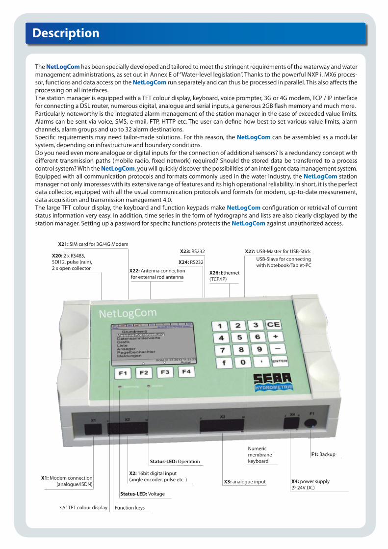
The NetLogCom has been specially developed and tailored to meet the stringent requirements of the waterway and watermanagement administrations, as set out in Annex E of “Water-level legislation”. Thanks to the powerful NXP i. MX6 proces-sor, functions and data access on the NetLogCom run separately and can thus be processed in parallel. This also affects the processing on all interfaces.The station manager is equipped with a TFT colour display, keyboard, voice prompter, 3G or 4G modem, TCP / IP interface for connecting a DSL router, numerous digital, analogue and serial inputs, a generous 2GB flash memory and much more.Particularly noteworthy is the integrated alarm management of the station manager in the case of exceeded value limits. Alarms can be sent via voice, SMS, e-mail, FTP, HTTP etc. The user can define how best to set various value limits, alarm channels, alarm groups and up to 32 alarm destinations.Specific requirements may need tailor-made solutions. For this reason, the NetLogCom can be assembled as a modular system, depending on infrastructure and boundary conditions.Do you need even more analogue or digital inputs for the connection of additional sensors? Is a redundancy concept withdifferent transmission paths (mobile radio, fixed network) required? Should the stored data be transferred to a process control system? With the NetLogCom, you will quickly discover the possibilities of an intelligent data management system.Equipped with all communication protocols and formats commonly used in the water industry, the NetLogCom station manager not only impresses with its extensive range of features and its high operational reliability. In short, it is the perfectdata collector, equipped with all the usual communication protocols and formats for modern, up-to-date measurement, data acquisition and transmission management 4.0.The large TFT colour display, the keyboard and function keypads make NetLogCom configuration or retrieval of current status information very easy. In addition, time series in the form of hydrographs and lists are also clearly displayed by the station manager. Setting up a password for specific functions protects the NetLogCom against unauthorized access.
X1: Modem connection
(analogue/ISDN)
3,5“ TFT colour display Function keys
Status-LED: Voltage
X2: 16bit digital input(angle encoder, pulse etc. )
Status-LED: Operation
X3: analogue input
Numericmembranekeyboard
X4: power supply(9-24V DC)
F1: Backup
X20: 2 x RS485,SDI12, pulse (rain),2 x open collector
X21: SIM card for 3G/4G Modem
X22: Antenna connectionfor external rod antenna
X23: RS232
X24: RS232
X26: Ethernet(TCP/IP)
X27: USB-Master for USB-StickUSB-Slave for connectingwith Notebook/Tablet-PC

Description
SD Card
Ethernet
USB / M
USB / S
Data logger
Language Alarm
Measurementmanagement
Pulse input1 x
16 Bit BCD input(8x Impuls)
Analog input5 x 0/4-20mA
(oder 3 x 0/4-20mA2 x 0-10V)1 x PT100
DCF77(Option)
Modem 3G4G (Option)
Analog1 SDNVOIP
(Option)
RS232
RS232
RS485
RS485
Serial inputSDI 12
Parameterization of sensors
Alarm configuration
Measurement data input
Software configuration for NetLogCom
All settings and configurations related to specific measurement sites can alternatively be carried out by notebook or tabletPC using the supplied „Configuration“ software (Windows):
tablet PC/notebook
Flowchart:

)
Redundency concept
For the realisation of a redundancy system in the water industry at HND levels (A-level), there are numerous options:
1) 1 logger, 1 and/or 2 transmission paths, 2 sensors (water level)
Configuration: 1 x NetLogCom via fixed network (TCP / IP), and/or via mobile network (3G/4G modem), 1 x water level sensor (eg SEBA-PS-Light-2) to RS485 input, 1 x water level (eg SEBA-Puls) 4-20 mA analogue input;
Measurement station
mobile communications
fixed network
Push
TCP/IP
GSM, GPRS,EDGE, UMTS,
HSPA+
Sensor 1
Sensor 2
Meteosat, Irridium, V-Sat
)
2) 2 Logger, 2 transmission paths, 2 sensors (water level), (physically independent)
Configuration: 1 x NetLogCom via fixed network (TCP / IP), 1 x NetLogCom via mobile network (3G/4G modem), 1 x waterlevel sensor (eg SEBA-PS-Light-2) to RS485 input, 1 x water level (eg SEBA-Puls) 4-20 mA analogue input;
Measurement station
mobile communications
fixed network
Push
TCP/IP
GSM, GPRS,EDGE, UMTS,
HSPA+Sensor 1
Sensor 2
Meteosat, Irridium, V-Sat
NetLogCom
NetLogCom No. 1
NetLogCom No. 2 network
network
(e.G. PS-Light2)
(e.G. SEBA-Puls)
Central
(e.G. PS-Light2)
(e.G. SEBA-Puls)
Central
simultaneously possible
Redundency concept
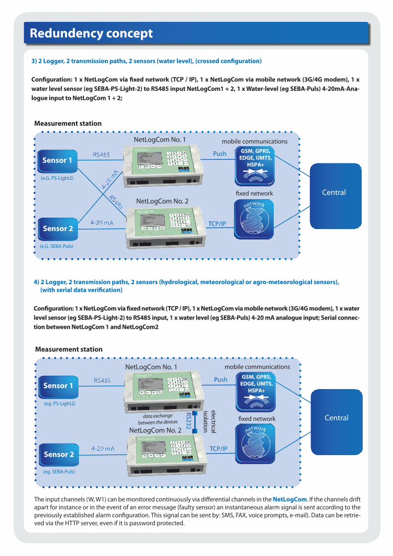
3) 2 Logger, 2 transmission paths, 2 sensors (water level), (crossed configuration)
Configuration: 1 x NetLogCom via fixed network (TCP / IP), 1 x NetLogCom via mobile network (3G/4G modem), 1 x water level sensor (eg SEBA-PS-Light-2) to RS485 input NetLogCom1 + 2, 1 x Water-level (eg SEBA-Puls) 4-20mA-Ana-logue input to NetLogCom 1 + 2;
)
4) 2 Logger, 2 transmission paths, 2 sensors (hydrological, meteorological or agro-meteorological sensors), (with serial data verification)
Configuration: 1 x NetLogCom via fixed network (TCP / IP), 1 x NetLogCom via mobile network (3G/4G modem), 1 x water level sensor (eg SEBA-PS-Light-2) to RS485 input, 1 x water level (eg SEBA-Puls) 4-20 mA analogue input; Serial connec-tion between NetLogCom 1 and NetLogCom2
Measurement station
Push
TCP/IP
GSM, GPRS,EDGE, UMTS,
HSPA+Sensor 1
Sensor 2
Meteosat, Irridium, V-SatNetLogCom No. 2
Measurement station
Push
TCP/IP
GSM, GPRS,EDGE, UMTS,
HSPA+
Meteosat, Irridium, V-Sat
NetLogCom No. 2
NetLogCom No. 1
)
Sensor 1
Sensor 2
NetLogCom No. 1
electricalisolation
RS232
data exchange between the devices
network
network
mobile communications
fixed network
(e.G. PS-Light2)
(e.G. SEBA-Puls)
Central
mobile communications
fixed network
(eg. PS-Light2)
(eg. SEBA-Puls)
Central
The input channels (W, W1) can be monitored continuously via differential channels in the NetLogCom. If the channels driftapart for instance or in the event of an error message (faulty sensor) an instantaneous alarm signal is sent according to thepreviously established alarm configuration. This signal can be sent by: SMS, FAX, voice prompts, e-mail). Data can be retrie-ved via the HTTP server, even if it is password protected.

Toolkit
Additional analogue and digital inputs and outputs:
With the help of external Bus Terminals (WAGO), the NetLogCom can be extended at any time. A bus coupler with Ethernet connection and corresponding input and output terminals are required for connection. The bus coupler communicates via a TCP / IP connection. The data are transferred to the station manager via the Modbus protocol.
Voice over IP (VoIP)
In addition to the standard integrated voice announcements via 3G modem, there is also the possibility to realise a VoIPconnection on-site with appropriate infrastructure (DSL connection). The VoIP module in the NetLogCom has its own network interface so that the announcement or error message does not run over the network of the station manager (Int-ranet). The VoIP module is instead installed in the NetLogCom fixed network modem (ISDN, analogue modem).
networkNetLogCom
VoIPconnection
VoIPServer
telephone network
bus coupler extension clamps
Digital input Digital output
Analogue input Analogue output
Alarm management
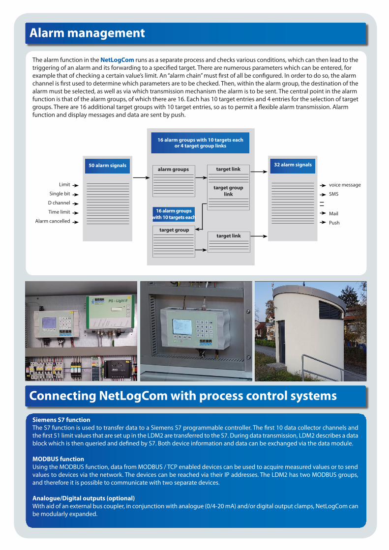
The alarm function in the NetLogCom runs as a separate process and checks various conditions, which can then lead to thetriggering of an alarm and its forwarding to a specified target. There are numerous parameters which can be entered, forexample that of checking a certain value’s limit. An “alarm chain” must first of all be configured. In order to do so, the alarmchannel is first used to determine which parameters are to be checked. Then, within the alarm group, the destination of thealarm must be selected, as well as via which transmission mechanism the alarm is to be sent. The central point in the alarmfunction is that of the alarm groups, of which there are 16. Each has 10 target entries and 4 entries for the selection of targetgroups. There are 16 additional target groups with 10 target entries, so as to permit a flexible alarm transmission. Alarmfunction and display messages and data are sent by push.
Limit
Single bit
D channel
Time limit
Alarm cancelled
voice message
SMS
Push
50 alarm signals
16 alarm groupswith 10 targets each
16 alarm groups with 10 targets eachor 4 target group links
32 alarm signalsalarm groups
target group
target link
target link
target grouplink
Connecting NetLogCom with process control systems
Siemens S7 functionThe S7 function is used to transfer data to a Siemens S7 programmable controller. The first 10 data collector channels and the first 51 limit values that are set up in the LDM2 are transferred to the S7. During data transmission, LDM2 describes a datablock which is then queried and defined by S7. Both device information and data can be exchanged via the data module.
MODBUS functionUsing the MODBUS function, data from MODBUS / TCP enabled devices can be used to acquire measured values or to sendvalues to devices via the network. The devices can be reached via their IP addresses. The LDM2 has two MODBUS groups, and therefore it is possible to communicate with two separate devices.
Analogue/Digital outputs (optional)With aid of an external bus coupler, in conjunction with analogue (0/4-20 mA) and/or digital output clamps, NetLogCom can be modularly expanded.
SEBA Hydrometrie GmbH & Co. KGGewerbestr. 61a • D-87600 Kaufbeuren
Tel.: +49 (0)8341 / 9648-0Fax: +49 (0)8341 / 9648-48
E-Mail: [email protected]: www.seba.de
Represented by:
Technical Data
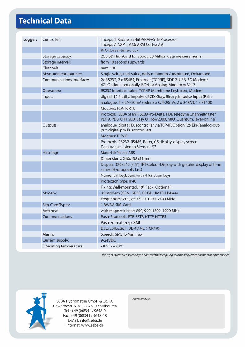
Logger: Controller: Triceps 4: XScale, 32-Bit-ARM-v5TE-ProcessorTriceps 7: NXP i. MX6 ARM Cortex A9RTC-IC-real-time clock
Storage capacity: 2GB SD FlashCard for about. 50 Million data measurementsStorage interval: from 10 seconds upwardsChannels: max. 100Measurement routines: Single value, mid-value, daily minimum-/-maximum, DeltamodeCommunications interface: 2x RS232, 2 x RS485, Ethernet (TCP/IP), SDI12, USB, 3G Modem/
4G (Option), optionally ISDN-or Analog-Modem or VoIPOperation: RS232 interface cable, TCP/IP, Membrane Keyboard, ModemInput: digital: 16 Bit (8 x Impulse), BCD, Gray, Binary, Impulse input (Rain)
analogue: 5 x 0/4-20mA (oder 3 x 0/4-20mA, 2 x 0-10V), 1 x PT100Modbus: TCP/IP, RTUProtocols: SEBA SHWP, SEBA-PS-Delta, RDI/Teledyne ChannelMasterPD19, PD0, OTT SLD, Easy Q, Flow2000, MIO, Quantum, level-online
Outputs: analogue, digital: Buscontroller via TCP/IP, Option (25 Ein-/analog-out-put, digital pro Buscontroller)Modbus: TCP/IPProtocols: RS232, RS485, Rotor, GS display, display screenData transmission to Siemens S7
Housing: Material: Plastic ABSDimensions: 240x138x55mmDisplay: 320x240 (3,5“) TFT-Colour-Display with graphic display of timeseries (Hydrograph, List)Numerical keyboard with 4 function keysProtection type: IP40Fixing: Wall-mounted, 19“ Rack (Optional)
Modem: 3G Modem (GSM, GPRS, EDGE, UMTS, HSPA+)Frequencies: 800, 850, 900, 1900, 2100 MHz
Sim-Card-Types: 1,8V/3V-SIM-CardAntenna: with magnetic base: 850, 900, 1800, 1900 MHzCommunications: Push-Protocols: FTP, SFTP, HTTP, HTTPS
Push-Format: zrxp, XMLData collection: DDP, XML (TCP/IP)
Alarm: Speech, SMS, E-Mail, FaxCurrent supply: 9-24VDCOperating temperature: -30°C - +70°C
The right is reserved to change or amend the foregoing technical specification without prior notice