Data Link Layer - incpaper.snu.ac.krincpaper.snu.ac.kr/images/d/db/2018cn_2_DataLink.pdfData link...
44
Data Link Layer Chong-kwon Kim SNU SCONE lab. Data Link Layer Data link layer is concerned with direct link networks Two nodes directly connected by a single point-to- point link A broadcast link segment with multiple attachments Different names at different layers Frame: L2 Packet, Datagram: L3 Segment: L4 Message: L7
-
Upload
nguyenkiet -
Category
Documents
-
view
255 -
download
0
Transcript of Data Link Layer - incpaper.snu.ac.krincpaper.snu.ac.kr/images/d/db/2018cn_2_DataLink.pdfData link...

Data Link Layer
Chong-kwon Kim
SNU SCONE lab.
Data Link Layer
Data link layer is concerned with direct link networks Two nodes directly connected by a single point-to-
point link
A broadcast link segment with multiple attachments
Different names at different layersFrame: L2Packet, Datagram: L3Segment: L4Message: L7

SNU SCONE lab.
Node Configuration Network adapter connects to I/O bus & network
link– Device driver manages a network adapter– Manage message passes between main memory and
network adapter buffer
CPU
Memory
CacheNetworkAdapter
I/O bus
(To network)
Example OpenWRT: An embedded kernel for WLAN APath9K: Device driver for Atheros WiFi chipsets
SNU SCONE lab.
Data Link Layer
Functions– Framing– Error control– Flow control– Medium access control (MAC) – LAN
Standard protocols– HDLC (High-level Data Link Control) - ISO– LAPB (Link Access Protocol Balanced) - ITU– LLC (Logical Link Control) - IEEE
• Type 1, 2, 3

Error Control
Chong-kwon Kim
SNU SCONE lab. 6
Error Control
First, detect error occurrences and then ensure correct transmission
Error types & detection methods– Bit error
• Error detection code such as CRC
– Lost or duplicated frames• Use sequence numbers (SN) that uniquely identify frames
Principle– A sender retransmits a frame repeatedly until it assures that
correct one is transferred
Two methods– Positive Acknowledgement (ACK) + Automatic retransmission
based on Timeout (TO)– Retransmission based on Negative Acknowledgement (NAK)

SNU SCONE lab. 7
ACK + Automatic Retransmission Basic action
Automatic Retransmission based on TO
What happens if packet / ACKis erred / lost ?
ACK
Sender
Receiver
1 2
Sender
Receiver
TO11
x
SNU SCONE lab. 8
ACK + Automatic Retransmission
Sender
Receiver
TO11
The ACK is lost and the receiver receives the same frameWhat would you do?1. Do nothing The sender will retransmit the same frame infinitely
2. Resend the ACK
x

9
ACK + Automatic Retransmission
Sender
Receiver
TO11 2
The frame #2 is lost, but two ACKs are received Should distinguish ACKs
Use Request Number (RN)RN specifies the next packet expecting instead of the last correctly received packet
Sender
Receiver
TO11 2
22
x
x
SNU SCONE lab. 10
NAK Based Method
When to send NAKs?– Receive corrupted frames
• How do you know that a corrupted frame is the frame?– Receive out of order frames
• Error control is triggered by following frames• What if there is a long gap between frames?• What if there is no next frame?• Lost NAK
NAK is used only as a supplementary mechanism
Sender
Receiver
21 1
1
x

SNU SCONE lab. 11
ARQ (Automatic Repeat reQuest) Stop-and-wait ARQ Continuous ARQ
– Go-back-N ARQ– Selective-repeat ARQ
Stop & Wait ARQ
Chong-Kwon Kim

13
Stop & Wait ARQ - 1Stop and Wait
Send a single packet(frame) and stop & wait for an Ack.
Stop & Wait ARQ - 2
Sender Algorithm
Step 0: Set SN = 0Step 1: Transmit a frame, Set the timer,
Wait for ACK with right RNStep 2: One of two events occurs
A: If receive right ACK before TO, Set SN (SN+1) mod 2, Goto Step 1
B: If TO, Goto Step 1 to retransmit
Receiver Algorithm
Step 0: Set RN = 0Step 1: Wait for a frameStep 2: Packet arrives
A: If errorless & SN = RN, Accept the frame, RN (RN+1) mod 2, Send ACK
B: Discard the frame, Retransmit ACK

Stop & Wait ARQ - Example
State– SN represents the sender’s state– RN represents the receiver’s state– Combined state = (SN, RN)
State transitions– (0, 0) -> (0, 1) -> (1, 1) -> (1, 0) -> (0, 0)– (0, 0) -> (0, 1), (1, 1) -> (1, 0) : Receiver knows the combined state– (0, 1) -> (1, 1), (1, 0) -> (0, 0): Sender knows the combined state– Sender & Receiver do not knows the combined state simultaneously
SN
RN
0 0 1 0
0 1 0 1
TO0 1 0 1
SNU SCONE lab.
Three Army Problem
Two Generals’ Problem (Byzantine Generals Problem )

17
– Propagation time : time taken for signal to travel from S to R. Thus first bit transmitted at t=0 arrives at R at t=Tp=d/V
– Transmission time : time taken to emit all bits of frame at sender=Tt=L/B
Utilization (Efficiency) of Stop & Wait
SNU SCONE lab. 18

19
– With stop & wait scheme, for high channel utilization, we need a low α (since U=1/(1+2 α ))
– In practice, it is not desirable to increase length L indefinitely• Error probability increases with L• Starvation/high avg. delay with multipoint lines• Realtime applications – short packet assembly time
– A more efficient scheme is called for, especially with HSN/WAN/satellite communication
Derive Utilizationusing the Little’s Theorem
Go-Back-N ARQ
Chong-Kwon Kim

SNU SCONE lab.
Go-Back-N Send multiple packets without receiving ACKs
– N: Window size• Maximum number of unacked packets that can be sent
– Stop and Wait is a special case of Go-back-N– Window: Packets that have been sent (but unacked) +
that can be sent• Window size = N• MinSN: First packet that are not ACKed yet• MaxSN: Highest packet that can be sent
MaxSN = MinSN+N-1• SN: Next packet to be sent
0 1 2 3 4 5 6 7 8 9 10 11 12 13 14
Example: N=8, MinSN = 3
Sent but not Acked yet
Go-Back-N Algorithm Sender algorithm
Receiver algorithm
Step 0: Set MinSN = SN = 0, MaxSN = MinSN+N-1,Send a frame, Set the timer
Step 1: Do one of three events foreverA: If SN < MaxSN, Set SN SN+1,
Transmit the next frame, (Set the timer)B: If ACK with RN > MinSN arrives, Set MinSN RN,
MaxSN MinSN+N-1C: If TO, Retransmit (Which frames ?)
Step 0: Set RN = 0Step 1: Receive frames forever
A: If the frame is error-free and RN = SN, Accept the frame, RN RN+1, Transmit ACK
B: O.W., Retransmit ACK

SNU SCONE lab.
Go-Back-N Example (N=4 case)
Properties of Go-Back-N– Properly designed, Go-Back-N achieves 100% utilization
– Right size of N ?– In case of a single packet loss/error
• Retransmit packets [MinSN, SN]– How about an ACK loss/error ?– How about out-of-sequence packets?
0 1 2 3 4 1 2 3 4
RN 0 1 2 3
SN[0, 3] [1, 4] [2, 5]
TO
SNU SCONE lab.
ACK Semantics Cumulative ACK
– ACK (RN) acknowledges packets up to (RN-1) Lost ACKs may be recovered
0 1 2 3 4 5 2 3 5
RN 0 1 2 3 4 5
SN[0, 3] [2, 5] [4, 7] [5, 8]
TO
Compare to Point ACK

SNU SCONE lab. 25
– Utilization : U is a function of a and N• Case 1 : N > 1 + 2a
– Frame 1 ACK reaches to the sender before transmission of Nth
frame continuous transmission possible
Link Utilization of Go-Back-N
SNU SCONE lab. 26
– Case 2 : N < 1 + 2a : U = N / (1+2a)• Wasted time between N and 1 + 2a

YA ARQ: Selective Repeat
Survey the Internet and learn Selective Repeat ARQ
SNU SCONE lab. 27
Medium Access ControlBasic & ALOHA
Chong-kwon Kim

SNU SCONE lab. 29
Taxonomy of Medium Access Methods
MAC protocols can be considered as distributed ATDM
ContentionBased
SNU SCONE lab. 30
Contention Based Method Every station is a peer
– No master-slave relation
Fully distributed, non-coordination method– Judge & behave based on locally available information
Stations use care not to interfere other– But should be aggressive to earn the fair share
Collisions still can occur
Aloha
CSMA/CA
CSMA/CD
CSMA

SNU SCONE lab. 31
ALOHA - 1 Proposed by Abramson in 1970 Implemented and used at the Univ. of Hawaii U. Hawaii campuses
SNU SCONE lab. 32
ALOHA - 2 Transmit a frame and check if the frame is transmitted correctly
– ACK– Retransmit in case of no ACK
Example

SNU SCONE lab. 33
ALOHA – Performance Analysis
A is successful if– No attempt in (t-1, t) &&
(t, t+1)
n stations each with p attempt rate A frame sent at time t is successful if only one attempt in (t, t+1)
and no attempt in (t-1, t)
Binomial distribution, Bin(x; n, p) = nCx ∙𝑝 ∙ 1 𝑝
Total attempt rate = n∙p
P(success) = b(1; n, p)∙b(0; n, p) = nC1 𝑝 1 𝑝 · nC0 1 𝑝
= 𝒏 · 𝒑 · 1 𝑝 𝟐 𝟏
Tfr = 1(unit time)
ALOHA – Performance Analysis Note b(x; n, p) ≈ Po(x; G) where G = n∙p if n is large and p is small
SNU SCONE lab. 34
The throughput for pure ALOHA is S = G × e −2G .The maximum throughputSmax = 0.184 when G = (1/2)
What happens if G=n∙p is too small OR too large?

SNU SCONE lab. 35
ALOHA - 3 Procedure
Slotted ALOHA & CSMA
Chong-kwon Kim

Problem of ALOHA Problem with Pure (Unslotted) Aloha
– An attempt may be interfered by later attempts– Vulnerable time is long
SNU SCONE lab. 37
SNU SCONE lab. 38
Slotted Aloha - 1 Solution
– Synchronize the transmissions – How to synchronize stations?
(know the beginning of slots)

SNU SCONE lab. 39
Slotted Aloha - 2 A station that has a packet to send, waits until the next
slot
A slot is either Idle, Success or Collision– Idle: No arrival during the previous slot time– Success: Exactly one arrival– Collision: More than one arrival
Time
Success Idle Idle Collision
SNU SCONE lab. 40
Slotted Aloha – Performance Analysis A slot is successful if
– There is exactly one attempt during the previous slot
Pr(1 arrival in a unit time) = G×e-G
The throughput for slotted ALOHA is S = G × e−G .
The maximum throughput Smax = 0.368 when G = 1

Slotted Aloha - Problem
Slotted Aloha is unrealistic– Synchronization is a big problem– One solution is to have a control node and the node transmits
beacons that announce the beginning of slots– Or adopt NTP (Network Time Protocol)
A centralized controller brings out other problems
SNU SCONE lab. 41
SNU SCONE lab. 42
CSMA (Carrier Sense Multiple Access) - 1
Two problems of slotted Aloha– Long Idle slot– Long Collision slot
How to shorten the Idle slot? Pure Aloha blindly accesses the medium even though there are on-
going transmissions On the other hand, slotted Aloha blindly postpones transmission
even though the medium is idle Check the medium and transmit frames immediately if the medium is idle, not waiting until the next slot Carrier sensing
TimeSuccess Idle Idle Collision

SNU SCONE lab. 43
CSMA - 2 How to determine if the medium is idle or not?
– Measuring the signal strength, voltage level
CSMA– Listen-before-talk
TimeSuccess Idle Idle Collision
Time
CCA: Clear Channel AssessmentRSSI: Received Signal Strength Ind.
Performance
SNU SCONE lab. 44
P-Persistent CSMA

CSMA/CD
Chong-kwon Kim
46
CSMA Collision CSMA still suffers from
collisions

SNU SCONE lab. 47
CSMA/CD (Collision Detection) Recall the second problem of Slotted Aloha
– Long Collision Slot
How to shorten the length of collision slots? Method
– While transmitting a frame, listen if there is a collision– If collision, terminate the transmission immediately
How to detect collisions?– In the case of a single transmission, the voltage level confined within
a certain level– Two or more concurrent transmissions cause higher than the normal
voltage level
How about Wireless link?
SNU SCONE lab. 48
CSMA/CD – CD Duration How long should we listen for collision?
– Two times of the maximum propagation delay
SNU SCONE lab. 49
CSMA/CD Procedure
Failed transmission
Further (personal) investigations Various persistence methods
– Non/1/p-persistent
The speed of Ethernet increased from 10 Mbps 100 Mbps 1 Gbps 10 Gbps 100 Gbps. Problem of high speed Ethrrnets. Solutions.
Modern layer 2 switches no longer use CSMA/CD. They use switch fabrics that enable multi-point to multi-point dedicated full-duplex connections.
SNU SCONE lab. 50

Wireless LAN
Chong-kwon Kim
SNU SCONE lab. 52
Wireless Characteristics Performance of wireless links is
much lower than that of wired links
Root cause:
Attenuation of wireless medium is much higher than that of wired medium
WHY?
Attenuation

SNU SCONE lab. 53
IEEE 802.11 WLAN Standard IEEE 802.11 a/b/g
.11g OFDM
6~54 Mbps
2.4 GHz
DS
1 & 2 Mbps1 & 2 Mbps
.11a OFDM
.11b CCK
5 GHz
5.5 & 11 Mbps
6~54 Mbps
802.11(1997)
1999 (up to 11 channels @ 20MHz)
FH IR
2.4 GHz
2003(Both 2.4 GHz & 5 GHz)
PMD
PLCP
MAC
LLC
TCPIP
SNU SCONE lab. 54
802.11 PHY - 1 802.11 - 1997
– Three physical layer specifications operating at 1 and 2 Mbps
Two additional parts in 1999 - 802.11a and 802.11b
IEEE 802.11b– 2.4-GHz band at 5.5 and 11 Mbps– Complementary code keying (CCK) modulation– Input data treated in blocks of 8 bits at 1.375 MHz
• 8 bits/symbol 1.375 MHz = 11 Mbps

802.11 PHY - 2 802.11a
– 5-GHz band up to 54 Mbps– Uses orthogonal frequency division multiplexing (OFDM)– Multiple carrier signals at different frequencies– Data rates 6, 9, 12, 18, 24, 36, 48, and 54 Mbps
IEEE 802.11g (2002)– Extends IEEE 802.11b to
higher data rates– Combines 802.11a and b
IEEE 802.11n (2006)– 100 Mbps
55
SNU SCONE lab. 56
Transmission RatesAMC: Adaptive Modulation & Coding
Learn: Performance Anomaly Problem

SNU SCONE lab. 57
Topology Infrastructure Mode
– All packets pass through the Access Point (AP)– No direct communications between Mobile Stations (MS, or
client/host)
Ad-hoc mode– Peer-to-peer (station-to-station) direct communications
AP APAP
SNU SCONE lab. 58
IEEE 802.11 Architecture

SNU SCONE lab. 59
IEEE 802.11 – BSS / ESS Smallest building block is Basic Service Set (BSS)
– One AP and multiple stations– Same MAC protocol– Competing for access to same shared wireless medium– BSSID (= MAC addr. of the AP)
ESS (Extended Service Set)– Two or more BSSes interconnected by DS– Appears as a single logical LAN to LLC
AP– Logic within station that provides access to DS– Provides DS services in addition to acting as station
Portal– Integrate IEEE 802.11 architecture with wired LAN
Wireless LAN- Signal & Interference
Chong-kwon Kim

Data
A
SNU SCONE lab. 61
Basic Operation In CSMA/CD, we can be almost sure that a frame is
delivered successfully in case of no collision No longer true in wireless networks
– Collision Detection is impossible
1. How do you know a frame is successfully transmitted? Use ACK
2. No ACK Retransmission ACK should be transmitted before any other frames
How about CSIn wireless links?
SNU SCONE lab. 62
Wireless Characteristics - CS Carrier sense
– Detect EM signal strength
In wired networks, Sender’s CS ≈ Receiver’s CS
In wireless networks, CS at sender ≠ CS at receiver
How do you know the receiver’s channel status?
O R
O R T
T

SNU SCONE lab. 63
Hidden / Exposed Terminal Hidden Terminal
Problem– C cannot sense BA
transmission and attempts to send a frame
Exposed Terminal Problem– C can send to D without
disturbing AB transmission
– But, C thinks the medium is busy
SNU SCONE lab. 64
RTS/CTS & Virtual CS Request To Send (RTS) & Clear To Send (CTS)
– Short control frames that specifies the intention to transmit (RTS) and willingness to receive (CTS)
Specifies the remaining time of the transaction in RTS/CTS frames Network Allocation Vector(NAV)
NAV
NAV

SNU SCONE lab. 65
RTS/CTS & Hidden Terminal RTS/CTS can mitigate the hidden terminal problem
Suppose you hear an RTS but not a CTS, what will you do?
Suppose you hear a CTS without RTS, what will you do?
SIFS
How long should you wait beforesending your frame?
SNU SCONE lab. 66
RTS/CTS & Exposed Terminal
RTS/CTS exchange cannot solve the exposed terminal problem

Wireless LAN- Protocol
Chong-kwon Kim
SNU SCONE lab. 68
Inter- Frame Space (IFS) An ACK should be immediately delivered
IFS: Minimum time that the medium should be idle to transmit a frame
SIFS (short IFS): – For all immediate response actions
• RTS-CTS, DATA-ACK, Poll response
PIFS (point coordination function IFS): – Used by the centralized controller in PCF scheme when issuing polls
DIFS (distributed coordination function IFS):– Used as minimum delay for asynchronous frames contending for access
If SIFS < DIFS, then data frames cannot intervene DATA-ACK transaction
SNU SCONE lab. 69
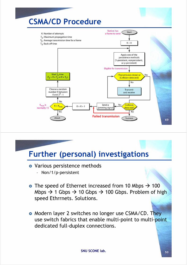
Media Access Control Distributed wireless foundation MAC (DWFMAC)
– Distributed access control mechanism
Lower sublayer is distributed coordination function (DCF)– Contention algorithm to provide access to all traffic
Point coordination function (PCF)– Centralized MAC algorithm– Contention free
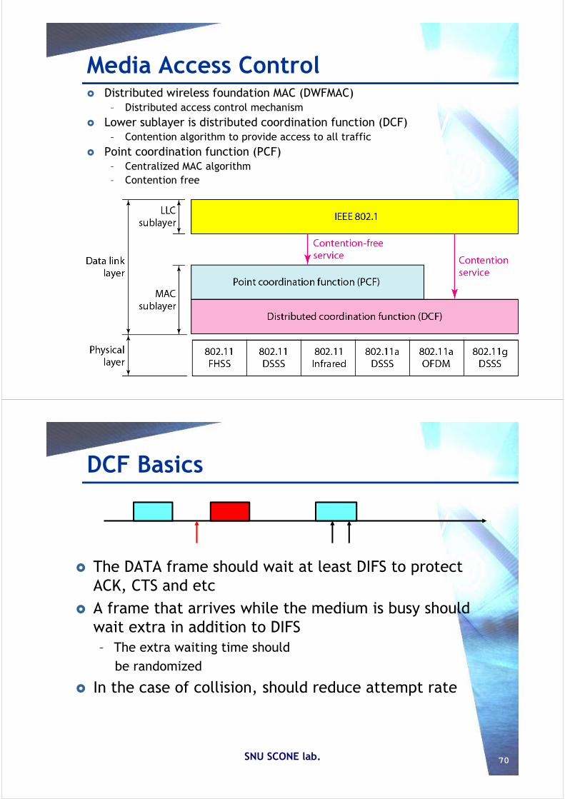
DCF Basics
The DATA frame should wait at least DIFS to protect ACK, CTS and etc
A frame that arrives while the medium is busy should wait extra in addition to DIFS– The extra waiting time should
be randomized
In the case of collision, should reduce attempt rate
SNU SCONE lab. 70

DCF Basic
SNU SCONE lab. 71
DIFS
New packetMedium = Idle
Idle for DIFS
DATA
DIFS
New packetMedium = Busy
Idle for DIFS
DATADATA
Slot, Δ
Random Backoff
After DIFS, decrease backoffcounter by one if the medium isidle for ΔIf medium is busy, freeze countdown
Backoff counter = Rand[0, CW]
Backoff counter = 0
Collision?
SNU SCONE lab. 72
BEB (Binary Exp. Backoff) Collision = Overloaded Contention Window (CW) Backoff delay = Random (0 .. CW) At the beginning, CW = CWmin
For each unsuccessful transmission, double CW up to CWmax

BC=1
BC=2
BC=5
Example
SNU SCONE lab. 73
Data
A
Data
A DataSTA A
STA B
STA C
STA D
SIFS
DIFSDIFS DIFS
SNU SCONE lab. 74
DCF – CSMA/CA
BC=0 & !TxPend
TxSuccess TxFail
Access Control
Back-off
Access Control Tx Idle
Access Control
Tx & Wait Ack
TxPend & CCA>DIFS
CCA>DIFS & BC=0 & TxPend
TxPend & CCA.busy
BC=BC-1
Slot & CCA>DIFS
GetBC
GetBC
CW=CWmin DoubleCW
Wait DIFS
CCA>DIFS
!(CCA>DIFS)
CA (Collision Avoidance)RTS/CTS exchange is optional

Frame Format PLCP Header - DSSS
Sync 128 (56)
SFD 16
Length16
Service8
Signal8
CRC16
MPDU
192 us1 Mbps 1/2/5.5/11 MbpsRate Indication
No. of Bytes
Preamble (srt/long) PLCP header
MAC Frame Fields (1)
Frame Control:– Frame type/sub-type
• Control, management, or data– To DS/From DS– More fragment– Retry– Power Mgmt– More data– WEP– Order
Duration/Connection ID:– Indicates time (in s) for successful transmission of MAC frame– May contain AID (Association ID)

MAC Frame Fields (2) Sequence Control:
– 4-bit fragment number subfield• For fragmentation and reassembly
– 12-bit sequence number – Number frames between given transmitter and receiver
Frame Body:– MSDU (or a fragment of)
• LLC PDU or MAC control information
Frame Check Sequence:– 32-bit CRC(Cyclic Redundancy Check)
Address FieldsTo DS From DS Address 1 Address 2 Address 3 Address 4
0 0 DA SA BSSID -
0 1 DA BSSID SA -
1 0 BSSID SA DA -
1 1 RA TA DA SA
Address 1: All stations filter on this address Address 2: Transmitter address (TA)
- Identify transmitter to address the ACK frame to Address 3: Dependent on To and From DS bits Address 4 : Only needed to identify the original source ofWDS(Wireless DS) frames

Wireless LAN- Other Features
Chong-kwon Kim
AP Discovery To use AP
1. Discovery 2. Authentication3. Association
Scan– Discover APs in transmission range
Active scan, Passive scan Passive scan
– Client listen “Beacon” frames that AP transmits periodically
Active scan– Client probe the existence of APs by sending “Probe request”
frame– AP replies with “Probe response” frame– “Probe response” frame is similar to Beacon frameSNU SCONE lab. 80

Authentication
Open system and Shared key system
SNU SCONE lab. 81
Authentication Auth. Req
Challenge
Answer
WEP Key
Association
SNU SCONE lab. 82
AssociationResponse
State 1UnauthenticatedUnassociated
Class 1Frames
State 2AuthenticatedUnassociated
Class 1 & 2Frames
State 3AuthenticatedAssociated
Class 1,2 &3Frames
DeauthenticationNotification
DeassociationNotification
Authentication
Association
AssociationRequest
Allocate Association ID

Power Saving Energy is very scarce resource in mobile devices Network interfaces consume sizable amount of energy
SNU SCONE lab. 83
Turn off network interfaces when not in use PSM (Power Saving Mode)
– Sleep state– Listen
To sleep– Signals to the AP not to send frames
How to resume communication (Wakeup)?– Transmission (Station AP)– Reception (AP Station)
How to Conserve Energy?
Packet Reception - PSM
Beacon(TIM) Interval DTIM Interval
DTIMDTIM
AP transmits beacons every beacon interval (~100msec)- Defer if channel is busy- PS nodes wake up for beacon reception
TIM(Traffic Indication Map)- Indicate the existence of backlogged unicast traffic to PS nodes- PS node may request packet transmission
Broadcast packets are announced by a Delivery TIM(DTIM) and are sent immediately afterwards
- DTIM interval is a multiple of TIM interval
AP
Stationwakeups
Broadcast

Delivery in PS Mode If TIM indicates frames buffered
– STA sends PS-Poll to AP and stays awake to receive data
Learn– U-APSD (Unscheduled Automatic Power Saving Delivery)
SNU SCONE lab. 85
PS-Poll
DATAAP
Station
802.11e QoS Priority and Parameterized QoS
Priority scheme– EDCA (Enhanced DCF Channel Access)– Four access classes– Different CW and AIFS
Parameterized QoS scheme– HCCA(Hybrid Coordination Function Channel Access)– PCF based resource allocation
SNU SCONE lab. 86

Access Classes
SNU SCONE lab. 87
AC Description CW Min. AIFS
0 Background 15 7
1 Best Effort 15 3
2 Video 7 2
3 Voice 3 2
2 0~3 slots
2 0~7 slots
3 0~15 slots
7 0~15 slots
Random BCAIFSSIFS
AC3
AC2
AC1
AC0