Data Driven Services · Data Center Expert Day Intelligent data needs intelligent power Data Center...
191
Data Center Expert Day Intelligent data needs intelligent power Data Center Expert Day, December 1 st , 2016, New York City December 2, 2016
Transcript of Data Driven Services · Data Center Expert Day Intelligent data needs intelligent power Data Center...
Data Center Expert Day Intelligent data needs intelligent power
Data Center Expert Day, December 1st, 2016, New York City
December 2, 2016

Data Center Expert Day Agenda
2-Dec-16 | Slide 3 © ABB
10:00 – 10:20 AM – Welcome and introduction
Brian Davis, Data Center Industry Segment Leader, North America
10:20 – 10:40 AM - Technology advances for the future of Data Centers
Dave Sterlace, Global Head of Data Center Technology
10:40 – 11:30 AM - Saving time and money with data center automation
Rich Ungar, Business Manager, Data Center Automation
Data Center Expert Day Agenda
2-Dec-16 | Slide 4 © ABB
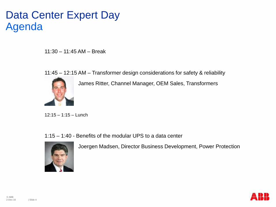
11:30 – 11:45 AM – Break
11:45 – 12:15 AM – Transformer design considerations for safety & reliability
James Ritter, Channel Manager, OEM Sales, Transformers
12:15 – 1:15 – Lunch
1:15 – 1:40 - Benefits of the modular UPS to a data center
Joergen Madsen, Director Business Development, Power Protection
Data Center Expert Day Agenda
2-Dec-16 | Slide 5 © ABB
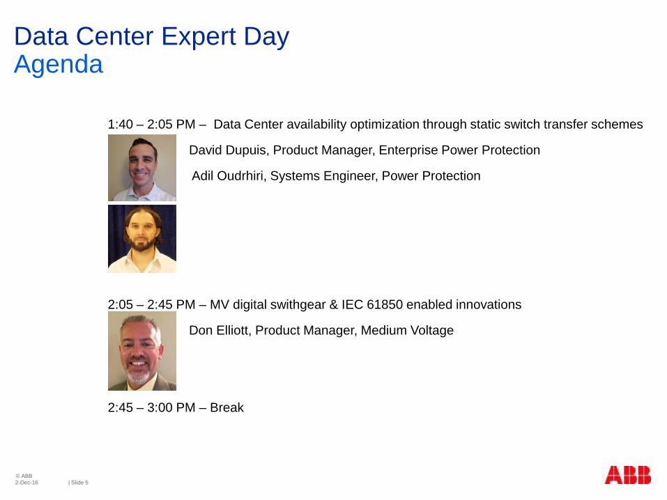
1:40 – 2:05 PM – Data Center availability optimization through static switch transfer schemes
David Dupuis, Product Manager, Enterprise Power Protection
Adil Oudrhiri, Systems Engineer, Power Protection
2:05 – 2:45 PM – MV digital swithgear & IEC 61850 enabled innovations
Don Elliott, Product Manager, Medium Voltage
2:45 – 3:00 PM – Break

Data Center Expert Day Agenda
2-Dec-16 | Slide 6 © ABB
3:00 – 3:45 PM – Substation design & renewable integration
Matthew Vaughn, Business Development Manager, Substations
Pat Ervin, Compact Substation Business Development Manager
3:45 – 4:15 PM – Modular Systems: E-houses and Product Packaging Solutions
Sarah C. Butz, ABB Packaging, Marketing Engineer
4:15 – Reception with refreshments

ABB – A global technology pioneer Leading market positions in power & automation
December 2, 2016
~135,000 employees
Present in
countries ~100
Formed in
1988 merger of Swiss (BBC, 1891) and Swedish (ASEA, 1883) engineering companies
In orders (2015)
billion 36 $
Presenter
Presentation Notes
ABB - publicly owned company with head office in Switzerland

ABB in the United States
December 2, 2016
Investment and growth
Markets Largest One of ABB’s ~20,500
U.S. employees (~15% of ABB)
Entered U.S. in
1989 via
Westinghouse T&D acquisition
$10.5 billion invested
since 2010
including 13 acquisitions
~14,000 U.S. customers
24,997 Safety Obs. Tours (2015)
160+ U.S. Locations
Nearly
60 Manufacturing
Locations
Region Headquarters Cary, N.C.

How ABB is organized Four divisions
Discrete Automation and Motion products, systems and services help improve efficiency and reliability throughout the energy value chain.
Electrification Products delivers products and systems designed to connect, protect and control electrical systems, ensuring reliability, efficiency and safety for your equipment and personnel.
Process Automation products, systems and services help optimize operations and processes across the energy value chain.
Power Grids helps improve efficiency and reliability throughout the power value chain from generation to transmission and distribution.
Electrification Products
5,374 U.S. employees
Discrete Automation and Motion
7,590 U.S. employees
Power Grids
4,439 U.S. employees
Process Automation
2,266 U.S. employees
December 2, 2016
December 2, 2016
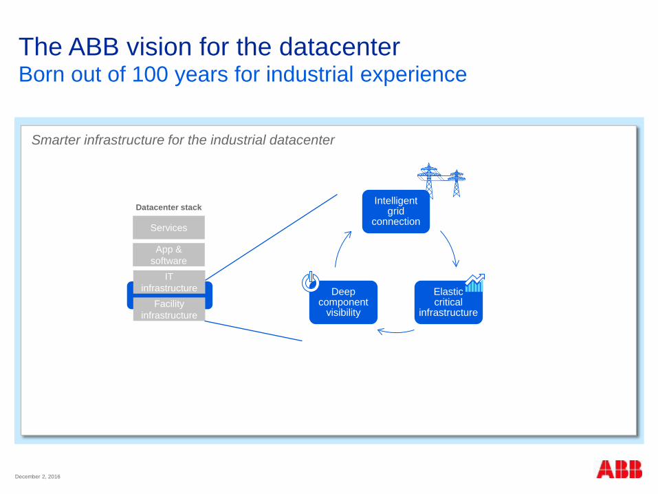
The ABB vision for the datacenter Born out of 100 years for industrial experience
Smarter infrastructure for the industrial datacenter
Intelligent grid
connection
Elastic critical
infrastructure
Deep component
visibility
Services
App & software
IT infrastructure
Facility infrastructure
Datacenter stack

December 2, 2016
A rich portfolio… Technology update

Internet of things and its impact An ABB perspective
Dave Sterlace, Global Head of Technology, ABB
December 2, 2016

What do you need to know about IoT? Unprecedented Scale
Month DD, YYYY
20B connected devices by 2025 per Gartner 50B per Cisco!

What do you need to know about IoT? Wireless
Month DD, YYYY
100k cell sites in NYC in 2025 vs 3000 today

What do you need to know about IoT? Latency
Month DD, YYYY
…will drive Edge

What do you need to know about IoT? Security
Month DD, YYYY
…Target’s breach went in through HVAC “back door” in ‘12

What do you need to know about IoT? Flexibility
Month DD, YYYY
…infrastructure must scale with IT loads

What do you need to know about IoT? Visibility
Month DD, YYYY
…infrastructure must scale with IT loads

How the data will be analyzed and used is crucial, new business models emerge.
ABB impact of the Internet of Things
Month DD, YYYY
Things Services People
Devices and machines communicate with each other, deliver data for Big Data.
Humans remain in charge, program and control the activities of things.

Inst. base
Internet of Things Improves productivity, efficiency and reliability
Month DD, YYYY
Service dispatcher
Secure conn.
Web portal Field service mgt
Customer
ABB consultant
3rd Party service provider
Collaborating service expert
Service center
Analytics
Other data
Field service
engineer

Characteristics of Future Data Centers
Smarter infrastructure for the industrial data center
Intelligent Grid
Connection
Elastic Critical
Infrastructure
Deep component
visibility
Services
App & Software
ICT Infrastructure
Facility Infrastructure
Datacentre Stack
Presenter
Presentation Notes
Talk to customers, here’s what they’re doing, consolidating, automating, etc.

Intranet of Things – Internet of Things
Intelligent devices with sensors are providing large amounts of data
Essential requirements remain (safety, reliability), cyber security and data privacy become more important
People
People will remain in control of the production process. People will be the decision makers
Services
Services becomes more advanced through data analytics.
Opportunities for new service models that build on collaboration.
Prepared for the internet of things? Absolutely
Month DD, YYYY

Saving time and money with Data Center Automation
Rich Ungar

Learning from other industries is an opportunity
Food & Beverage
Semiconductors
Oil & Gas
Pharmaceuticals
Chemicals
Automotive
© ABB Group – ABB Business Proprietary 2016
Highly available infrastructure
Super efficient industrial operations
Automated workload management
Data center industrialization is inevitable Data Center Automation takes industrial technologies and applies them to the data center
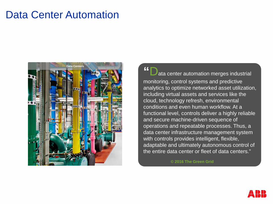
Data Center Automation
“Data center automation merges industrial monitoring, control systems and predictive analytics to optimize networked asset utilization, including virtual assets and services like the cloud, technology refresh, environmental conditions and even human workflow. At a functional level, controls deliver a highly reliable and secure machine-driven sequence of operations and repeatable processes. Thus, a data center infrastructure management system with controls provides intelligent, flexible, adaptable and ultimately autonomous control of the entire data center or fleet of data centers.” © 2016 The Green Grid
Data Centers

Silos
Facilities Engineering, Operations & Planning IT DevOps, Planning
‘Islands of automation’ increase risk, cost, inefficiency © ABB Group – ABB Business Proprietary 2016
IT
Network Compute
Data Services
Power
EMS PMS
Cooling
BMS CMS
CRACs VFDs Airflow
Chillers Economisers Pressure
Substation Switchgear
Utility Meter Power Meters Generators
BCM UPS PDU
White Space
BCM Security
Fire Control
VESDA
Hotspots Server Mon.
Plug in Strips
App. Mon.
Network Mon.

IT
Network Compute
Data Services
Power
EMS PMS
Cooling
BMS CMS
CRACs VFDs Airflow
Chillers Economisers Pressure
Substation Switchgear
Utility Meter Power Meters Generators
BCM UPS PDU
White Space
BCM Security
Fire Control
VESDA
Hotspots Server Mon.
Plug in Strips
App. Mon.
Network Mon.
2 Enable optimal
management of space, power and cooling for
the entire facility
3 Establish full IT
workload management
1 Integrate all physical
infrastructure monitoring, control and automation
All physical and virtual infrastructure as one
Converged DevOps and Management
Comprehensive management of the 3 Cs in your data center: Cost Capacity Control
Eliminate the silos

Step 1 - Integrate all physical infrastructure monitoring, control and automation

Common user interface
Open architecture with standardized integration
Use of high-availability design and redundancy
Segmented networks and servers
Common API for integration with 3rd-party applications
What does an integrated Data Center Automation system look like?
© ABB Group December 2, 2016 | Slide 29

CAPEX benefits of one system
© ABB Group – ABB Business Proprietary 2016
One control technology One HMI to commission No system integrations No finger-pointing between controls vendors
Reduce troubleshooting and rework delays Speed up commissioning time Less training required Fewer spares parts needed
Cost reductions through lower overhead & coordinated construction activities
One contract One site team, one project manager One support contract

OPEX benefits of a Data Center Automation solution
© ABB Group – ABB Business Proprietary 2016
Know where your money is going
Predict when expenses will occur Optimize your data center to reduce costs and improve
performance
Plan your future activities with accurate insight
Better information means reduced risk

Reduced risk, cost and inefficiencies for data center operations and management teams by creating an Operational Management platform that provides real-time, high-reliability monitoring, control & automation.
Schematic based approach Connect to everything Rich visualisation & dashboards
Know everything about your data center - NOW

Advanced alarming and alarm diagnostic capabilities, for fast troubleshooting Sophisticated reporting and analytics environment
Seeing the truth behind the data

Condition-based monitoring and prognostics integrated with maintenance management tools
Looking into the future

Asset Condition Monitoring
Maintain aging assets while under increasing pressure to hold or reduce operations and maintenance spend while increasing uptime and reliability.
Asset Health (ACM) is a method for Data Centers to assess critical assets based on the combination of the criticality and risk of failure.
Asset Condition Monitoring Systems combine operational and information technologies, along with product and diagnostic expertise.

Asset Health Solution
Results and Communications; Actionable; Integrated into Work and Asset Management
4
Digital Dashboards
Field Inspections/ Communications & Work
Notifications
Work and Asset Management – Work Orders
Min
com
Data Acquisition; Data from a variety of sources ranging from
Near real time data (GIS, mobility,
Historian, EAM)
Enterprise Data (EAM data
warehouse, market databases, ERP etc)
Real time data (condition, EMS-SCADA, monitors
and sensors, DCIM)
1 Decision Support; KPIs and Workflows to Prioritize Investment and Maintenance Work
KPIs That Matter
Adhoc capabilities
Packaged Analytics
Notifications & Reports
KPI Dashboards
3 Data Aggregation and Analytics; Leveraging ABB Experts , Statistics, and Condition Assessments
Analytics, Algorithms and Engineering best practices
determine total risk
2
Thermal risk
Dielectric Risk
Mechanical risk
Accessory risk
Miscellaneous risk

Transformer Aging & Failure Model
© ABB Group December 2, 2016 | Slide 37
Overview Thermal aging Temperature Chemical aging Moisture Oxygen Acids
Mechanical aging Overstress Vibration / Nr. of operation
Electrical aging Overvoltage Overcurrent Harmonics
STRENGTH
STRESS Life Extension
End of Life With
Retrofit
Fault Occurs
Margin
End of Life Without Retrofit
Retrofit
OPERATIONAL LIFE

Transformers Life Extension Options & Considerations Risk Of Failure Determination
ROF
Short-Circuit Risk
Thermal Risk
Dielectric Risk
Accessory Risk
Miscellaneous Risk
Nameplate Information Application Information Loading History Service Record Mechanical Design Information Electrical Design Information Thermal Design Information Through-Fault History Site Inspection Information Bushing type and Diagnostic Data Conservator type and Condition Load Tap Changer Type and Diagnostics Cooling Equipment Type and Condition DGA and Oil Quality Data Electrical Test Data (PF, Resistance, PD.) Maintenance History Failure History of Similar Units Leaks and Environmental Concerns Relative Importance to System
Input Data Risk Categories ROF

Battery Monitoring and Alarms Float Current Monitoring
2-Dec-16 | Slide 39 © ABB
Battery condition evaluation and alarm with following parameters
Float current
Float voltage
Temperature
AC/DC resistance or conductance
Electrolyte level (where available)
Battery Risk of Failure calculation
Input
AC and DC floating current measurements
Thresholds presetting
Ambient temperature
Output
Battery condition level based on AC/DC floating current measurement
Note: Float current measurement needs correction based on temperature
Reference: IEC TR62060

Load
Events, alarms Trxf. 1 Trxf. 2 Trxf. 3 … Trxf. n
Top Oil
T. amb
Tap pos.
Trxf. fingerprint
Gas
Sen
sor
H2O
Sen
sor
Bus
hing
LTC
PD
FRA
/Tra
nsie
nts
Off
line
DG
A
Rou
tine
test
s
FRA
, DFR
, Z, e
tc
Mai
nten
ance
act
ions
MTM
P R
isk
of F
ailu
re
Static data or information Dynamic data/information On going development
Offline Databases
Online Sensors
Kelman Minitrans Hydran M2 Kelman Transfix
Off
line
SO
T, F
uran
s
SC
ADA
Asset Health Center – Information Flow & Analysis
Enterprise
Report Recommend Actions Update Risk of Failure
Statistics
Equations
Expertise Computation Performance
Models

Basic Asset Monitor Library
Limit Check Asset Monitor – limit condition for analog vibration measurement
Flow Delta Asset Monitor – monitors allowed difference between e.g. steam flow and feed water flow
Counter Check Asset Monitor – monitors number of valve strokes, motor starts, breaker activations etc.
Runtime Asset Monitor – monitors any equipment runtimes
X-Y Profile Deviation Asset Monitor – monitors feed pump capacity (flow vs current)
Compressor/Pump Curves Asset Monitors - Imports pump curves and compares actual and expected performance
Presenter
Presentation Notes
Optional slide. Can be replaced by 800xA Asset Optimization demo. The Basic Asset Monitor Library includes a set of standard asset monitors for different types of monitoring (see examples in slide). These standard asset monitors can be applied on any object in the system. E.g. motor runtime can be monitored on motor objects in an AC450 controller (800xA for Advant Master), AC 800M controller (AC 800M Connect) and a 3:rd party controller (Siemens, Rockwell using PLC Connect). Some of the asset monitors includes faceplate elements to be used in the object faceplates (e.g. runtime indication in a motor faceplate or valve stroke indication in a valve faceplate displayed in the slide).

Expected Benefits
Consolidated data on asset condition available to stakeholders in a timely fashion Providing situational awareness Support for making maintenance and capital
replacement decisions Decreased reliance on specific local knowledge
Deployment of advanced decision support tools Early warning signals of potential failures
Make operational decisions with actionable intelligence Improved asset utilization
major maintenance is performed less frequently on healthy assets
Workforce efficiencies Specific tasks at the right time
Clear path to Condition Based Maintenance
Uptime and Reliability

Step 2 - Enable optimal management of space, power and cooling for the entire facility

Monitoring, reporting and analytics of energy utilization including the optimization of the use of supply resources to meet the predicted consumption at minimum total
cost.
Energy optimization

Optimize space, power and cooling capacity through intelligent placement of IT assets. Perform modeling and “what-if” analyses and automate and manage
workflow processes.
Capacity Management
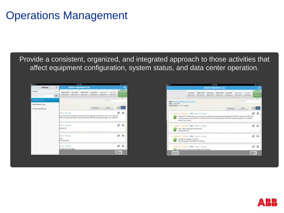
Provide a consistent, organized, and integrated approach to those activities that affect equipment configuration, system status, and data center operation.
Operations Management

Root Causes of Unplanned Outages
Poneman Institute Study January 2016

The Impact of Inefficient Work Execution
Managing complex operations, there is no room for
compromises or short cuts
Work crew safety
Compliance, Audit Reporting
Company reputation
Overall system reliability

When Operations Management processes are weak …
Tracking operations status to regulatory requirements
Logging operation activities
Needed data in multiple systems & formats
Supporting Data Center activities online and during outages
Equipment configuration control for worker safety
Rely on human experts to pull everything together in high pressure work environment
Gathering field information for timely Decision making

The Value of an Operations Management Solution
Know that worker safety is not compromised while increasing plant efficiency
Know that the work is done right with quality and safety
Know that your plant is operating at peak performance
Improve worker safety, equipment performance, work effectiveness, and regulatory compliance
Operations Management

Operations Management Features and Benefits
Key Features Clearance – assists in implementing, controlling, and
executing a plant’s lockout procedure Operator Rounds – automates the tasks of collecting,
storing, and analyzing equipment operating data Narrative Logs – records and qualifies events which occur
during an individual’s shift watch Notice of Change (NoC) – manages the complete life-cycle of
an organization’s NoC process Mobile Logbook – allows desktop log entries and associated
plant data to be transferred to, and accessed on an operator’s mobile device, along with providing more timely access of plant activities to enterprise level decision makers
Key Benefits Worker Safety - meet safety standards for the workers, plant
and environment Plant Reliability - extend asset life, preserving plant integrity
and configuration Productivity - do things once, do things right – the first time Communications and efficiency - Improves decision making
with ease of access to information across all key plant personnel - and not only subject matter experts
Governance / Compliance - ensure public and stakeholder confidence, ensure regulatory compliance and create an environment of continuous improvement
Costs – reduce costs through effective issue prioritization and leverage performance improvements to processes and equipment
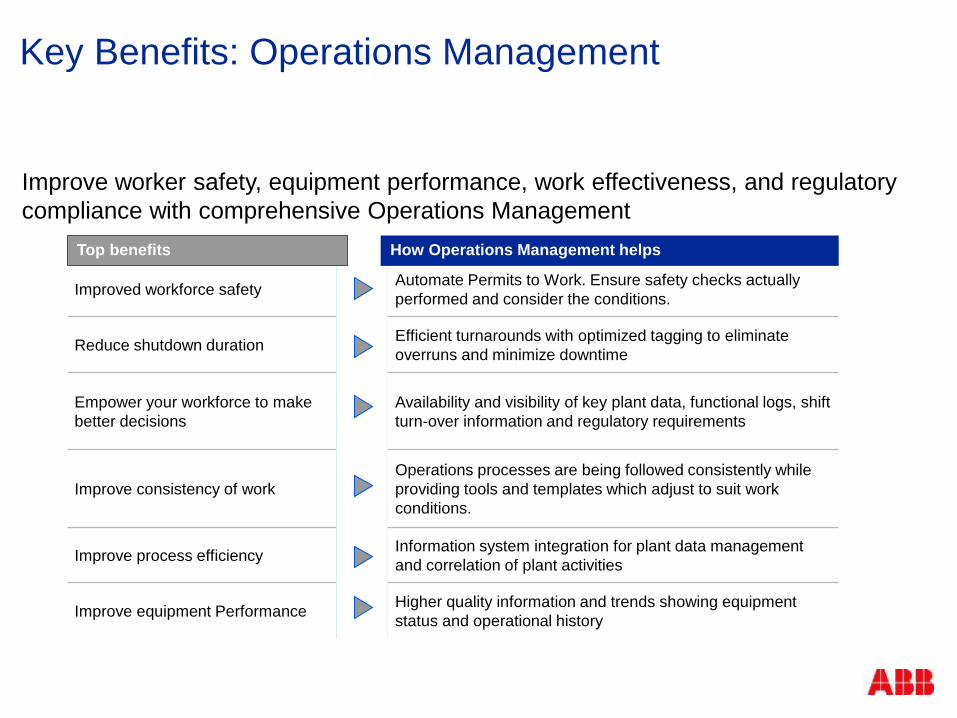
Key Benefits: Operations Management
Improve worker safety, equipment performance, work effectiveness, and regulatory compliance with comprehensive Operations Management
Improved workforce safety Automate Permits to Work. Ensure safety checks actually
performed and consider the conditions.
Reduce shutdown duration Efficient turnarounds with optimized tagging to eliminate overruns and minimize downtime
Empower your workforce to make better decisions
Availability and visibility of key plant data, functional logs, shift turn-over information and regulatory requirements
Improve consistency of work Operations processes are being followed consistently while providing tools and templates which adjust to suit work conditions.
Improve process efficiency Information system integration for plant data management and correlation of plant activities
Improve equipment Performance Higher quality information and trends showing equipment status and operational history
Top benefits How Operations Management helps

Step 3 - Establish full IT workload management

The industrialized data center Fully integrated facility and IT
© ABB Group – ABB Business Proprietary December 2, 2016 | Slide 54
Cooling Power
White Space
IT
Substation Switchgear
Utility Meter Power Meters Generators
BCM UPS PDU
EMS
PMS
CRACs VFDs Airflow
Chillers Economisers Pressure
Hotspots Server Mon. Plug in Strips
App. Mon.
Network Mon.
Network Compute
Data Services
BMS
CMS
BCM
Security Fire Control VESDA

Collect data into one place.
Simulate possibilities.
Put into action.
Ask what-ifs. Create business
cases. Capacity planning.
Automate. End-to-end intelligence.
Get end-to-end insight.
Analyze. Real-time KPIs and
benchmarks. Data visualization.
✓
Aggregate. Analyze. Hypothesize. Automate.
Speed of business goes from weeks/months to minutes/hours – with total governance.
Datacenter Automation
Platform
Decouple data and infrastructure.
Optimal utilization. Repeatable. Auto-scaling.
Aggregate for full spectrum of machine
knowledge. Full transparency.
The industrialized data center Fully integrated facility and IT

Conclusion: Learning from other industries is essential
Food & Beverage
Semiconductors
Oil & Gas
Pharmaceuticals
Chemicals
Automotive
© ABB Group – ABB Business Proprietary 2016
Transformer design enhancements for safety and reliability
Jamie Ritter, ABB Power Grids, Channel Manager, Dry-type Transformers
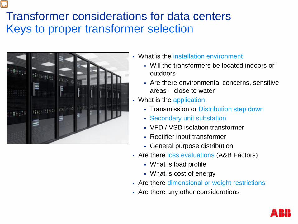
Transformer considerations for data centers Keys to proper transformer selection
What is the installation environment Will the transformers be located indoors or
outdoors Are there environmental concerns, sensitive
areas – close to water What is the application
Transmission or Distribution step down Secondary unit substation VFD / VSD isolation transformer Rectifier input transformer General purpose distribution
Are there loss evaluations (A&B Factors) What is load profile What is cost of energy
Are there dimensional or weight restrictions Are there any other considerations
Presenter
Presentation Notes
These are some of the considerations (If located in sensative areas, counter measures have to be taken, the applications of the transformer (including load profile (overload), harmonics, height restrictions (overhead constraints) including when rigging equipment. Building Codes, etc.

1
2
3
4
5
6
8
Substation Transformers Medium-voltage
switchgear Generators Power quality
assessments HV UPS Low-voltage
switchgear
General Purpose UPS Intelligent power
distribution units Remote power panels
Isolation transformers Input transformers Rectifiers UPS
Internal distribution transformers
HVAC solutions High-efficiency motors Low-harmonic
variable frequency drives / inverters
Power generation Step up and collector
transformers Isolation transformers
Data center services Remote monitoring
1
2
3
4
5
6
8
8
Transformer considerations for data centers Typical locations of transformers in data centers
Presenter
Presentation Notes
70% of DC CAPEX is Electrical and about 35% of that is transformer content. With dry, second to utilities, Datacenters are the second largest application The topography for datacenters, but in regards to transformers continues to grow. Recent trends in renewables have created demand for step up units, including collector transformers and zig-zag grounding. Transformers = Power substations, distribution MV & LV, UPS power, PDU power, LV VFD, Isolation units, etc. ABB has the breadth of products to serve all areas as we have pointed out here.

Flammable / Non-Flammable
Lead-times, Product & Drawings
Environmental Considerations Integrated Solutions
Complexity of Coordination's
UL, FM, NEMA, ANSI, IEC, etc.
Additional Containment
Efficiencies Maintenance & Commissioning
Transformer considerations for data centers Distribution transformers – liquid or dry?
Presenter
Presentation Notes
All considerations listed are important when choosing the right product for the application, which we will go into several of these in detail.
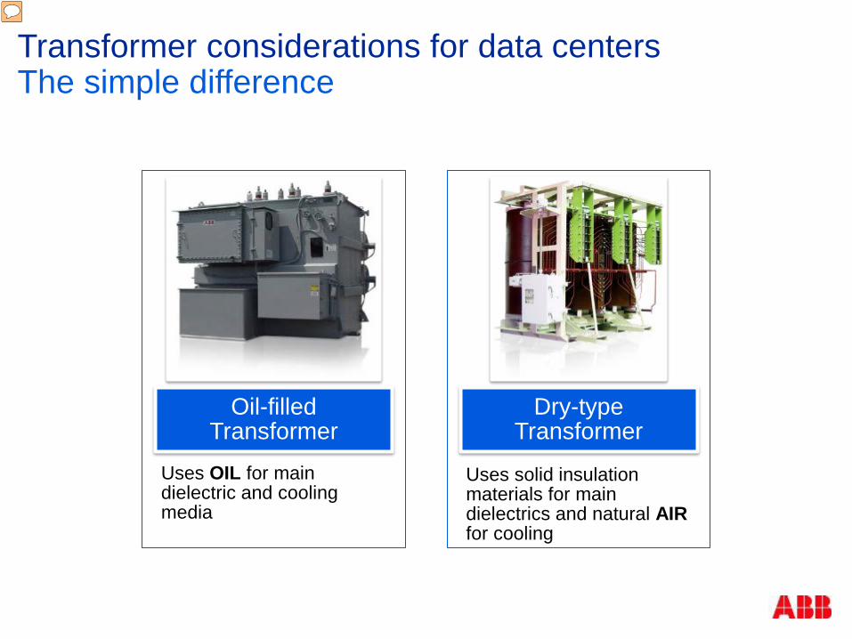
Transformer considerations for data centers The simple difference
Oil-filled Transformer
Uses OIL for main dielectric and cooling media
Dry-type Transformer
Uses solid insulation materials for main dielectrics and natural AIR for cooling
Presenter
Presentation Notes
Basic difference is the cooling media, dry uses solid insulation and air / vs. Liquid as a dielectric

Transformer considerations for data centers Key feature advantages
Key feature advantages
Oil-filled Feature Dry-type Size & Weight
Initial Cost Losses/Efficiency
Noise Overload capability
Fire Safety Environmental Safety
Total Installation Cost* Maintenance
Short Circuit Strength
*Driven mostly by regional building safety codes
Presenter
Presentation Notes
Listed are some of the main reasons people buy transformers, but for other reasons that include the safety of people , property and the environment, they select dry type

Transformer considerations for data centers
Typical convention Dry type inside Liquid filled outside
Reality is that dry type are used outdoors and liquid filled are used indoors
High temperature dielectric fluids are classified less flammable
Additional fire suppression systems may be required
Liquid filled units sometimes leak
Additional fluid containment may be required
Location considerations
Presenter
Presentation Notes
So we will start with environment and fire risk, which ultimately affect the location of the dist. transformers In sensitive ecosystems, fluid containment is necessary. Environmental impact with natural ester fluid High fire point fluids help with indoor

Transformer considerations for data centers
Dry-type aren’t restricted to indoors and liquid filled aren’t just outdoors
Advantages for locating units outside
Reduce HVAC costs
Reduce floor space
Reduce utility bills
Disadvantages for locating units outside
Adds cost of bus duct
Can create voltage regulation issues for sensitive equipment, across the line motor starters
Increased security for MV outside
Location considerations
Presenter
Presentation Notes
All advantages to placing units outdoors, but again due to security measures these days (this could be costly) As you can see, these units are housed in a channel that is protected -Ballistic transformer that could be potentially offered in the future -Boots for insulators, coatings for tanks, netting for fences. Open air vaults. Is it public area or sensitive area.
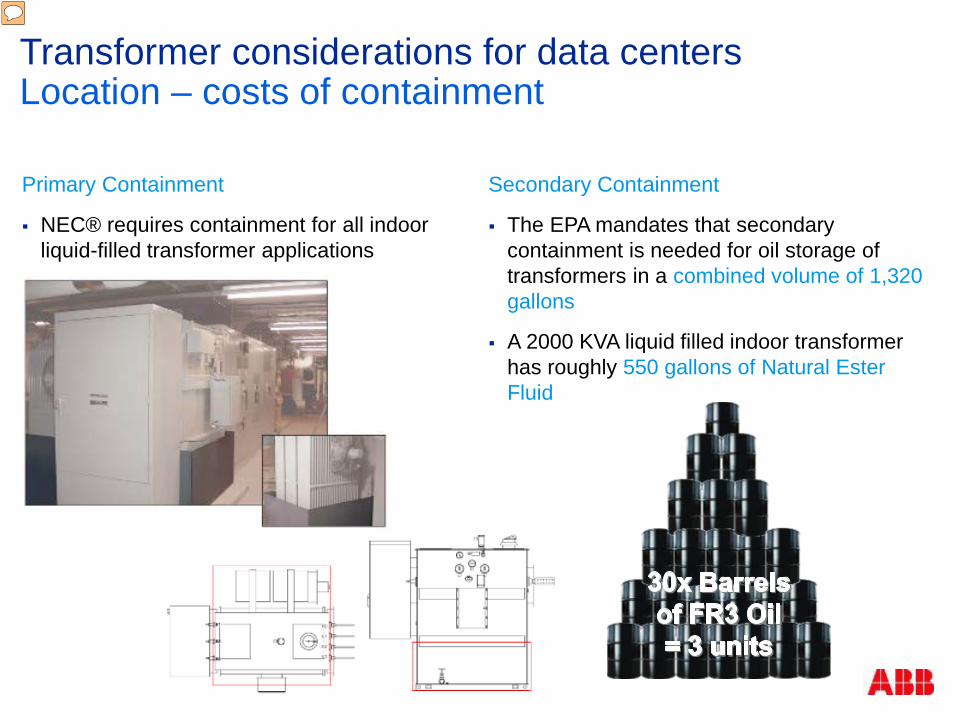
Transformer considerations for data centers Location – costs of containment Primary Containment
NEC® requires containment for all indoor liquid-filled transformer applications
Secondary Containment
The EPA mandates that secondary containment is needed for oil storage of transformers in a combined volume of 1,320 gallons
A 2000 KVA liquid filled indoor transformer has roughly 550 gallons of Natural Ester Fluid
Presenter
Presentation Notes
Due to the location, there could be additional costs. Primary: Distribution class (600 to 700 gallons of oil). NEC® requires containment for all indoor liquid-filled transformer applications Containment may take the form of complete room containment or: (door sills, dikes, curbing, or transformer containment pans) Custom-made containment pans, paint and drain plugs require custom design work to ensure that its tailored to fit, which can be costly ~ $5000 option about 15% of XFMR price Less flammable, but still flammable. Example is a grease fire, still can catch on fire 550x3 = 1650 (30 barrels of oil) Dry-type transformers do not require Oil Pollution prevention measures Liquid transformers must comply with the latest spill prevention control and countermeasures that are put into place The EPA mandates that secondary containment is needed for oil storage of transformers in a combined volume of 1,320 gallons 1x 2000 KVA liquid filled indoor transformer has roughly 550 gallons of Natural Ester Fluid

Transformer considerations for data centers Transformer oils
Increased safety
Non-flammable, but combustible
Flash point of 170°C Lowest cost transformer
technology Long history of being safe
Mineral Oil Ester Oils Dry Non-flammable, but still
combustible Flash point of 330-360°C 98% biodegradable seed oil
(when unused) Not suggested for indoors
Non-flammable AND non combustible
No flash point (nothing to ignite)
Only technology suited for indoor applications
Presenter
Presentation Notes
Alternative dielectric fluids (seed oil / FR3) are used in today’s liquid filled transformers, however: Max. flash point of 320ºC still exists Max. fire point of 350ºC still exists Dry-type offers the highest fire rating Non-flammable & self-extinguishing Inherently less risk of fire due to materials in construction and flash point is 350ºC Ester oil: Resilient against fire (fire point = 350ºC) 3 things required to ignite: Consistent temps above 400-500ºC Oxygen Ignition source Small amounts of ester oil will biodegrade, but gallons need to be contained / remediated Solidifies at -10 to 0ºC, requiring additional startup procedures / options. Mineral oil: Much lower flash / fire point Does not solidify until -40ºC EPA does not allow for a distinction b/w ester or mineral in the event of a spill

© ABB Group December 2, 2016 | Slide 67
Burnable materials for 1000 kVA oil and dry distribution transformers
In case of external fire:
Heat released: Oil transformer = 7 x Dry transformer
Dry Benefits: Minimal combustible fuels Self extinguishing / does not burn easily Increases safety for people and property
Material Type Oil Dry Solid Burnable 160 lbs 500 lbs Liquid Burnable 3,300 lbs N/A Total Weight 3,460 lbs 500 lbs
Transformer considerations for data centers Transformer oils continued
Presenter
Presentation Notes
Assumption 7.2 lbs per gallon of oil 1000 kVA has 440 gallons of oil Consistent temperatures at or above 400-500C, 2. oxygen, and 3. an ignition source Its not as much about the materials that make up the transformer, it’s the burnable liquid that continues to burn beyond the initial spark. An arc in the unit will not create a fire. Throwing a match into a bucket of the oil below its flame point (~350C) will not cause it to burst into flames (it will actually extinguish the match). If a building fire were to occur near the transformer room and the temperatures were sustained when it reached the transformer, upon an ignition source (melted bushing, internal arc due to system failure from the fire, etc.), the ester oil will most likely ignite and continue to burn; making it much more difficult for first responders to extinguish the fire before significantly more damage has occurred.
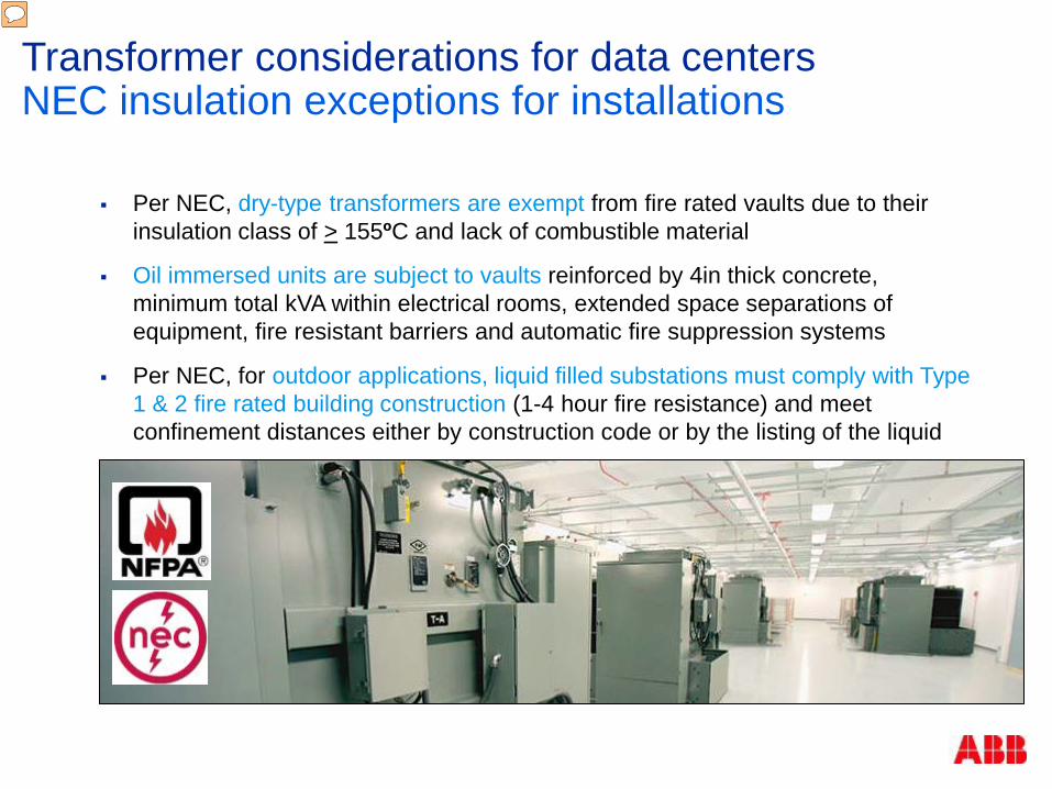
Per NEC, dry-type transformers are exempt from fire rated vaults due to their insulation class of > 155ºC and lack of combustible material
Oil immersed units are subject to vaults reinforced by 4in thick concrete, minimum total kVA within electrical rooms, extended space separations of equipment, fire resistant barriers and automatic fire suppression systems
Per NEC, for outdoor applications, liquid filled substations must comply with Type 1 & 2 fire rated building construction (1-4 hour fire resistance) and meet confinement distances either by construction code or by the listing of the liquid
Transformer considerations for data centers NEC insulation exceptions for installations
Presenter
Presentation Notes
Per NEC, dry-type transformers are exempt from fire rated vaults due to their insulation class of > 155ºC and lack of combustible material Oil immersed units are subject to vaults reinforced by 4in thick concrete, minimum total kVA within electrical rooms, extended space separations of equipment, fire resistant barriers and automatic fire suppression systems Per NEC, for outdoor applications, liquid filled substations must comply with Type 1 & 2 fire rated building construction (1-4 hour fire resistance) and meet confinement distances either by construction code or by the listing of the liquid

Wet pipe systems (code minimum)
Dry pipe systems
Pre-action systems
Water mist systems
Raised floors
Complex smoke detection
Transformer considerations for data centers Location – infrastructure costs for indoor
Combustible liquids require extensive & costly fire suppression systems
The power distribution rooms in Datacenters are considered Tier II hazards and require extensive containment
Determined by the impact, special fire walls and vaults may be required
Presenter
Presentation Notes
Per NEC regulation, dry-type transformers are exempt from fire rated vaults
Why the growing popularity for dry-type technologies? Failure modes
Injuries in the news:
“One injured in transformer explosion”
~ Istanbul, Jan 2016
“3 injured in transformer explosion”
~ Massachusetts, April 2016
“Transformer explosion kills 3, injures 5”
~ Nigeria, July 2016
“7 people injured in transformer explosion”
~ Pakistan, July 2016
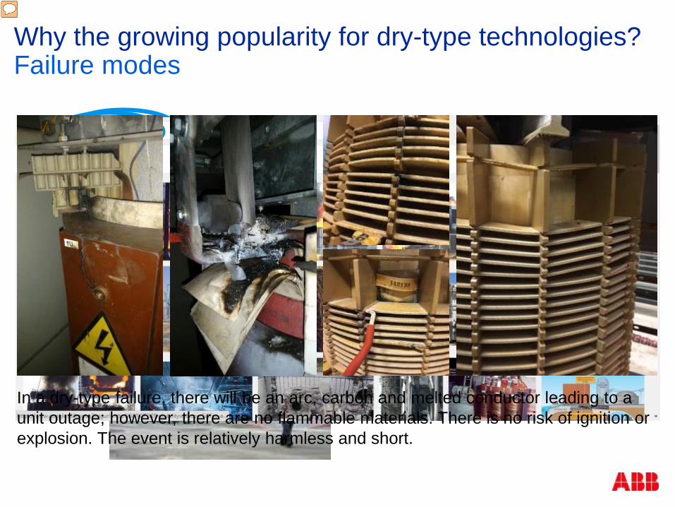
In a dry-type failure, there will be an arc, carbon and melted conductor leading to a unit outage; however, there are no flammable materials. There is no risk of ignition or explosion. The event is relatively harmless and short.
Presenter
Presentation Notes
One of the other important factors of product choice that I mentioned was short circuit strength or the failure mode As you can see, this what happens when an oil filled transformer fails (whats unique about this screen?) – Correct, no dry type transformers listed other than 2 pictures – but you don’t see fire. Most are outside in a protected area, contained where no people are around. However all oils are in some degree combustible. In a dry-type failure, there will be an arc, carbon and melted conductor leading to a unit outage; however, there are no flammable materials. There is no risk of ignition or explosion. The event is relatively harmless and short.
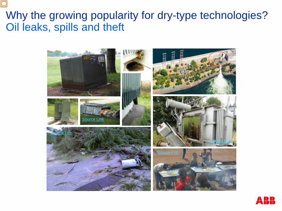
Why the growing popularity for dry-type technologies? Oil leaks, spills and theft
Source Link
Source Link
Source Link
Source Link
Source Link
Source Link
Presenter
Presentation Notes
Other growing popularity in dry is not just failure modes, but nuisance leaking, environmental factors and theft Storm events, pole mounted units Cars can hit liquid filled units �Theft – cooking potatoes in stolen transformer oil Oil is only biodegradable when unused – in emergency cases, they can train first responders to treat it differently. Oil is oil Now that oil is used it contains carbon and other hazardous materials that must be treated

Transformer design considerations in datacenter applications

Current Waveform of Switching Power Supply
Voltage or Current Waveform for linear loads (Sine Wave)
Non-linear Current and its fundamental plus 3rd and 5th harmonic component
Transformer considerations for data centers Application considerations - Harmonics
Static rectification devices - AC to DC power conversion devices - current is drawn only during a controlled portion of the waveform.
Single phase sources include computers and lighting ballasts.
Three phase sources include motor drives and uninterruptible power supplies.
Harmonics are fed back into the power system from these loads.
Harmonic can drive higher K factor ratings
Harmonics can create neutral grounding issues
Presenter
Presentation Notes
Anytime you are converting AC to DC, you are going to create harmonics. ABB can build units around these requirements, we use profiles to calculate, including K factor (which is the rating based on the amount of harmonics) We can also design for phase shifts, as with recent designs with Prince Basically the phase shift is adjusted so the phase are ~180degrees out of phase cancelling out the field. Example: two piece of bus are side by side, if the current in each bus is going in opposite directions then the magnetic field will cancel out. Same thing in the transformer we are adjusting the normal phase current to cancel out the harmonic current.

Liquid Filled
Dry Type
Dry-types are generally larger and 15% - 20% heavier than liquid-filled units
Transformer considerations for data centers Size and weight considerations
Presenter
Presentation Notes
I guess, I should ask the audience, is weight that much of a consideration these days? Are there ground bearing pressures of the floor that you have to meet due to the cooling that is duct under the datacenters? Dimensionally the 2 units can be conceiving, as you have to consider radiator fins, transition sections, fans and containment pans with liquid filled units. Weight maybe so not for new construction, but older warehouses being converted (load bearing 40 lbs per sqft). Reinforced floor to install electrical equipment indoors.

3P Power (kVA)
Dry-Type AA Sound Level
Liquid OA Sound Level
1000 64 dB 58 dB
2500 68 dB 62 dB
5000 71 dB 65 dB
7500 75 dB 67 dB
10000 79 dB 68 dB
15000 82 dB 70 dB
IEEE C57 NEMA TR1
Transformer considerations for data centers Sound levels
All of these are below industry standards
Newer technologies and materials can be used to lower sound levels for both types of transformers
Presenter
Presentation Notes
Drys don’t have the benefit of dampening of oil, so are generally louder Dry’s can install snubbers and springs, but can design most sound requirements with the use of higher grade core steel DB example chart – Lawn mowers (90db), Vacuum Cleaner (82DB). Even though transformers are louder, it can be addressed.

Loading beyond the limitations of either liquid or dry units can shorten the insulation life of either type of transformer, but can be made possible under certain conditions
Forced air (FA) cooling is a common accessory that can increase the loading of both types of transformers.
25% max for liquids, 50% max for dry medium size transformers
Transformer considerations for data centers Overloading
Presenter
Presentation Notes
Up to 50% with blowers on dry types 33% for liquids designing to get 133%

MAINTENANCE FREQUENCY OIL DRY Oil Level monthly YES NO Porcelain Insulator Cleaning annually YES NO Surface Cleaning annually YES YES Connections (Tighten) annually YES YES Painting State annually YES NO Oil Analysis (Dielectric Test) annually YES NO SILICAGEL (Verify and Replace) annually YES NO Accessories to Check Pressure Guage/Relief Buzcholz Over-Pressure Relay Oil Level WTI
Monthly annually annually annually annually
YES YES YES YES YES
NO NO NO NO YES
Transformer considerations for data centers Transformer maintenance
Presenter
Presentation Notes
+ MTTR, + $$ Spare Parts+ % Prob. Failure For dry’s surface cleaning, not even annual. Connections tightening are rare, but IR windows can be used to monitor

Transformer considerations for data centers Commissioning
Dry-type transformers are less complicated to commission. They are shipped and stored fully assembled and have no major pre-commission test requirements
Liquid immersed units require consideration for the liquids whether it is in the lifting, or in onsite filling, oil testing, or pre-commission testing
Additional assembly may be required with liquid filled units due to disassembled radiators and / or containment pans. However, if needed, dry-types can be disassembled in place and moved as component parts

Why the growing popularity for dry-type technologies? Total ownership costs; case study
Ester Oil Dry
Containment Pan
4%
18% Savings
65% 74%
Transformer Price
8%
Room Fire Supression
Tier One Data Center 42, 1.8 MVA, 13.8 kV transformers,
indoor & modular/skidded application Required transient protection because
of load switching with VCB’s
LV Tansition Section 3%
15% Transient Protection
5%
Receiving & Onsite Testing
5%
4%
Presenter
Presentation Notes
4% savings for oil handling / filling 15% transient protection (complete snubber, no monitoring)

Design / product considerations for contending with VCB’s

Vacuum circuit breakers can create over voltages on inductive equipment This is a system issue that needs to be analyzed taking the breaker device,
cable, distance between devices and transformer into consideration Factor into design up front Results are breaker manufacture specific Add protection only when and where needed
Transformer considerations for data centers Vacuum circuit breakers – switching & bypass
Presenter
Presentation Notes
A transformer failure due to switching is still a very rare event and is very dependent on the electrical system. VCB’s are good from a protection standpoint and interrupting currents, but can create collateral damage upstream and downstream from the equipment they are housed in It happens so rapidly (10x impulse strike) we suggest that this be factored into the design upfront (add protection when necessary). This happens across the coils itself. Looked at frequency of switching (on and off daily, once a month, 10’s /100’s of times during commissioning)

Transformer considerations for data centers Switching transients - Pperceptions of what’s happening When a breaker is switched…
The transient recovery voltage (TRV) may cause a re-strike in the breaker and send fast transients into the transformer
OR, the opening of the breaker traps currents causing voltage amplification due to ferroresonance
OR, the wide frequency sweep of switching transients matches the natural frequency of the transformer windings causing voltage amplification due to harmonic resonance (IEEE Std C57.142-2010)
OR, the fast frequencies themselves prematurely age the transformer insulation materials
Presenter
Presentation Notes
All transformers are susceptible, but VPI’s are the worst because they have the lowest dielectric resistance internal to the winding. Without protection, there may be arcing occurring in the winding. This acing will appear as increased gas levels under oil or slow insulation damage for drys. Overtime, this damage can be hazardous to the transformer.

168 kV peak terminal voltage on 125 kV BIL design
No protection
-10 -5 0 5x 10⁻⁴
-60
-40
-20
0
20
40
60
Time [s]
Vol
tage
[kV
]
-2 -1 0 1 2 3x 10⁻⁷
-60
-40
-20
0
20
40
60
Time [s]
Vol
tage
[kV
]
The rise time (∆t) is less than 0.1 µs and the rate of rise is about 600kV/µs
10x faster than impulse wave and occurs 30+ times in ~ 0.5 ms
Overvoltages also stress the middle of the winding; opposed to a lightning impulse that stresses the external and ends of the winding
Transformer considerations for data centers Understanding the problem (worst test case)
Voltage Across Coil
Zoom in (10-7) Zoom in (10-4)
Presenter
Presentation Notes
Tested all 3 technologies. Monitored prestrikes and reignitions through various switching cases (energized at no load, disconnection at no load, interruption of inrush current, interruption at load and interruption of short circuit current) ABB looked at every voltage on every tap, seeing where the peak voltage was seen (internal to the transformer) Also investigated types of load and distance the VCB from the transformer; highly inductive and close to transformer being worst case

Transformer considerations for data centers Two types of winding stress; must protect from both
Voltages spikes due to reignitions
Occurs when the voltage potential across the poles of the circuit breaker are still high enough to cause a spark across the terminals
Chance to occur during every switching event at load (seen on previous slide)
-10 -5 0 5x 10⁻⁴
-60
-40
-20
0
20
40
60
Time [s]
Vol
tage
[kV
]
67 67.5 68 68.5 69 69.5 70
-100
-50
0
50
100
Time[ms]
Vol
tage
[kV
]
trace45.dpd, voltages across halves of windings, U
U topU bottom
Voltage amplification due to resonance
Occurs when input voltage matches one of the natural frequencies of the transformer windings
Caused by a resonance between the transformer’s short circuit inductance and cable capacitances on the load side of the breaker
Rare event but needs to be protected from for a total solution
Each peak is a reignition
Presenter
Presentation Notes
The reignitions are worse than impulse, equate to 600kV BIL strikes + Voltage Rise due to Resonance amplification

Transformer considerations for data centers Current market solutions
+$20 kUSD to total price
+2’ box extension in any direction placed
Does not limit overvoltages to controlled levels
Monitoring/maintenance required
However, no field recorded failure cases
Line surge arresters RC snubber circuit Liquid hardened transformers
Not enough protection
Reduces peak overvoltages to ground, but overvoltages inside winding can still be very high
Field recorded failure cases
Higher line-end capacitance and BIL resistance
Survival not guaranteed in all system configurations
Arcing may still occur, creating gas
Recorded field failure cases due to VCB switching
-10 -5 0 5 10
-150
-100
-50
0
50
100
150
Time [ms]
Volta
ge [k
V]
"1U""1V""1W"
-10 -5 0 5 10-100
-80
-60
-40
-20
0
20
40
60
80
100
Time [ms]
Vol
tage
[kV
]
p , g p g
"1U""1V""1W"
Voltage to Ground
Voltage Across Winding
Transformer considerations for data centers Current market solutions – ABB’s TVRT™
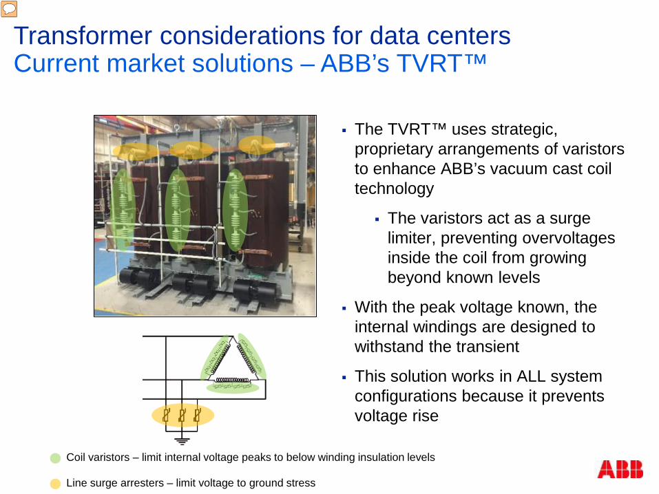
The TVRT™ uses strategic, proprietary arrangements of varistors to enhance ABB’s vacuum cast coil technology
The varistors act as a surge limiter, preventing overvoltages inside the coil from growing beyond known levels
With the peak voltage known, the internal windings are designed to withstand the transient
This solution works in ALL system configurations because it prevents voltage rise
Coil varistors – limit internal voltage peaks to below winding insulation levels
Line surge arresters – limit voltage to ground stress
Presenter
Presentation Notes
-5 0 5 10
-150
-100
-50
0
50
100
150
fran15.dpd, voltage across windings
Time[ms]
Vol
tage
[kV
]
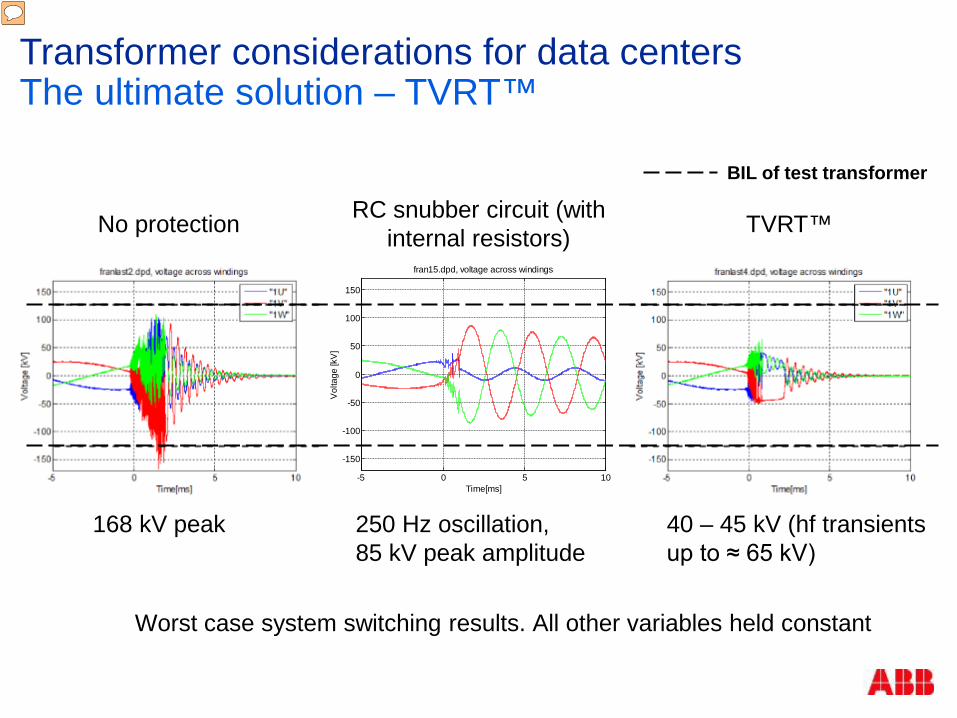
168 kV peak 40 – 45 kV (hf transients up to ≈ 65 kV)
No protection TVRT™ RC snubber circuit (with internal resistors)
250 Hz oscillation, 85 kV peak amplitude
BIL of test transformer
Worst case system switching results. All other variables held constant
Transformer considerations for data centers The ultimate solution – TVRT™
Presenter
Presentation Notes
Tradional VS. TVRT With RC Snubber (slows down peak voltages) but resonance still exists With TVRT Removes resonance; which is a industry perceived concern that kills transformer The Varistor arrangement data shows clear reduction in peak voltages and # of reignitions ABB’s winding frequency response analysis (FRA) showed clear 1st – 2nd order elimination of natural frequencies (protection against resonance amplification)
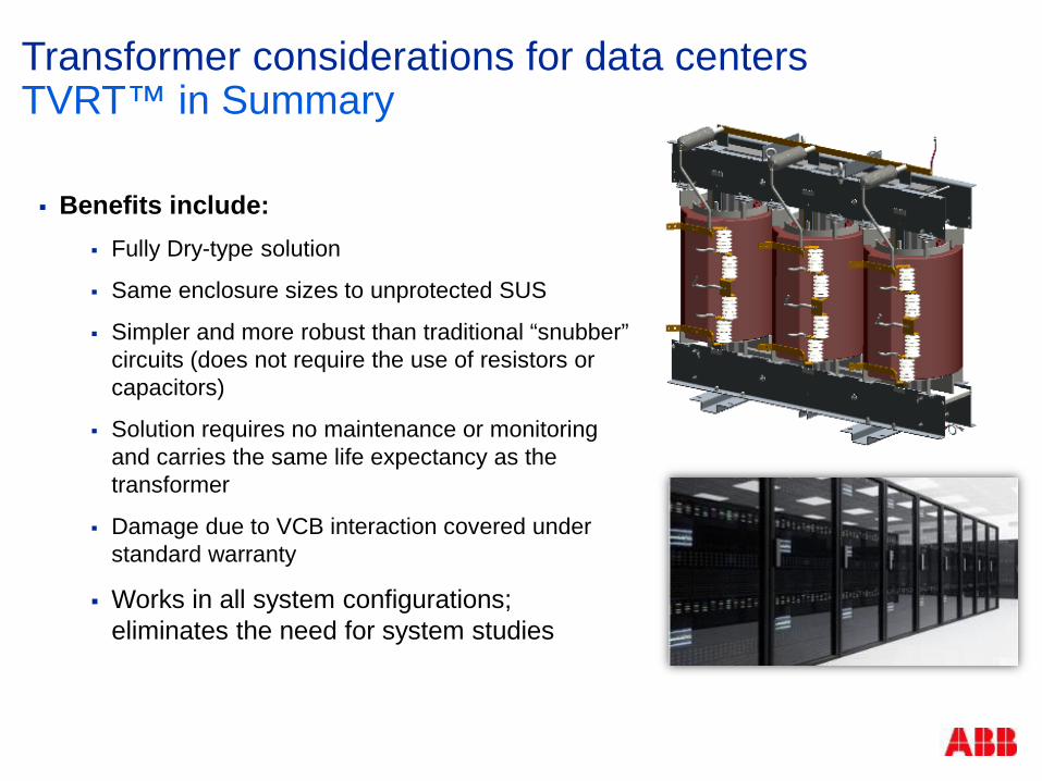
Transformer considerations for data centers TVRT™ in Summary Benefits include:
Fully Dry-type solution
Same enclosure sizes to unprotected SUS
Simpler and more robust than traditional “snubber” circuits (does not require the use of resistors or capacitors)
Solution requires no maintenance or monitoring and carries the same life expectancy as the transformer
Damage due to VCB interaction covered under standard warranty
Works in all system configurations; eliminates the need for system studies
Benefits of the modular UPS to a data center
Joergen Madsen
December 2, 2016

Data centers and UPSs Why UPS?
December 2, 2016
Critical load requiring constant uninterrupted power Mission critical applications require high power availability
Availability TCO

Agenda
December 2, 2016
UPS History
Current UPS Topologies
Market Drivers
Technology Trends
UPS Configurations & Architecture
Application Trends/Future
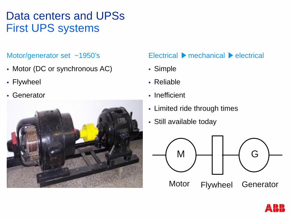
Motor/generator set ~1950’s
Motor (DC or synchronous AC)
Flywheel
Generator
Data centers and UPSs First UPS systems
Electrical mechanical electrical
Simple
Reliable
Inefficient
Limited ride through times
Still available today
Motor Flywheel Generator
M G

Data centers and UPSs Traditional North American UPS system
December 2, 2016
Transformer based static UPS SCR rectifier converting AC to DC
feeding inverter and charging Battery Inverter converting DC to AC
generating clean AC power for critical load
Energy storage, traditionally lead acid batter
Static switch to support critical load with direct utility power in case of high overload or UPS failure (lately also utilized for economy mode operation)
Transformers to ensure safe operating voltage for semiconductors (and provides galvanic isolation)
Transformer based double conversion UPS
~ _ ~
_
Battery
Static Switch
Inverter Rectifier

Market Drivers Total cost of ownership (TCO) – drivers
December 2, 2016
TCO drivers
$$... bottom line Cost savings –
eliminate losses Financial incentives Political Green profile Lobbying Legislation
U.S. Green Building Council
(USGBC)
PUE.. WUE.. CUE...
LEED Platinum Silver Gold

Technology trends Inverter - SCR -> IGBT topology
December 2, 2016
Static UPS SCR -> IGBT
Higher voltage rating eliminates need for transformer
Higher switching frequency allows reduction of filter size
High efficiency PWM control -> excellent
dynamic performance
L1 L2 L3
SCR based Inverter IGBT based Inverter
SCR 3-Level PWM Advanced PWM 2-Level PWM Step wave
IGBT

Technology trends TCO – technology drivers
December 2, 2016
Technology drivers – history
IGBT based inverter and rectifier
Reduced switching and filter losses
Online efficiency > 96%
Efficiency optimized at typical load level
Eco-mode efficiency up 99%
UPS efficiency – Eco-mode

UPS configurations and architecture
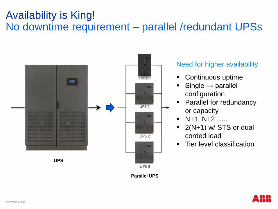
Availability is King! No downtime requirement – parallel /redundant UPSs
December 2, 2016
Need for higher availability
Continuous uptime Single → parallel
configuration Parallel for redundancy
or capacity N+1, N+2 ….. 2(N+1) w/ STS or dual
corded load Tier level classification
UPS
Parallel UPS

New modular UPS designs Monolithic vs. modular – addressing CapEx
December 2, 2016
Modular UPS designs Scalable – pay as you
grow Rightsizing Eliminate stranded
capacity Availability – integrated
redundancy Serviceability – low
MTTR Flexibility – easily
scalable to fit current power/redundancy need
CONCERNS ….
RELIABILITY
400kW + 400kW = 400kW N+1 Modular 5x100kW = 400kW N+1
Monolithic (traditional) UPS Design Modular UPS Design

Modular UPS – centralized design Centralized modular UPS
December 2, 2016
Traditional modular UPS design All control logic, static switch etc.,
centralized in UPS frame UPS frame is system control
cabinet (SCC) Several single points of failure
CONCERNS ….
RELIABILITY
Shared parts
Output to critical load
Bypass input
Control logic
DISPLAY
Power module
=
=
Power module
=
=
Power module
= =
Rectifier input
Battery

Modular UPS – decentralized design Decentralized parallel architecture (DPA)
December 2, 2016
All control logic, static switch etc., in each power module
Active power module is a complete UPS
Passive frame design High availability Eliminates single points of
failure Perfect load sharing Any UPS can be the logic
leader (multimaster system)
Output to critical load
UPS module
=
= = =
Control logic DISPLAY
UPS module
=
= = =
Control logic DISPLAY
UPS module
=
= = =
Control logic DISPLAY
Bypass input
Battery
Rectifier input

Modular UPS – decentralized design Conceptpower DPA UPS
December 2, 2016
Parallel configurations Scalable – vertically and
horizontally 100kW to 3MW, 480V Online-swap modularity
(OSM) Serviceability – low MTTR
Horizontal scalability Cabinets in parallel configuration
Vertical scalability 1 – 5 modules in one single cabinet

Applications trends/future
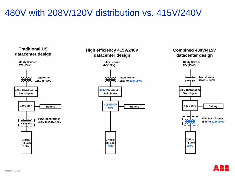
480V with 208V/120V distribution vs. 415V/240V
December 2, 2016
Traditional US datacenter design
480V Distribution Switchgear
480V UPS
Utility Service MV (15kV)
Transformer 15kV to 480V
PDU Transformer 480V to 208V/120V
Critical (IT) Load
120V
Battery
480V Distribution Switchgear
480V UPS
Utility Service MV (15kV)
Transformer 15kV to 480V
PDU Transformer 480V to 415V/240V
Critical (IT) Load
240V
Battery
415V Distribution Switchgear
415V/240V UPS
Utility Service MV (15kV)
Transformer 15kV to 415V/240V
Critical (IT) Load
240V
Battery
High efficiency 415V/240V datacenter design
Combined 480V/415V datacenter design

Medium Voltage UPS
December 2, 2016
15kV Distribution Switchgear
15kV UPS
Utility Service MV (??kV)
Transformer ??kV to15kV
Transformer 15kV to 415V/240V
Critical (IT) Load
240V
Battery

Summary
Online double conversion with full VFI operation is still the dominating UPS design – primarily transformerless design, due to higher efficiency.
After several years of efforts to increase efficiency, now up to 98% online efficiency with SiC based semiconductors, very little room for further improvement.
Economy mode – the market has been very reluctant to adapt, and with very high online efficiency – limited gains.
“Exotic” voltages and configurations not likely to gain significant traction – do not offer significant benefit over current solutions (code, hardware availability, and safety issues).
Future (and current) focus on “Rightsizing” – solutions that can eliminate/limit stranded capacity – to lower Cap-Ex and maintenance cost – need for scalable solution that easily adapt to ever changing load conditions – flexibility is key.
Trend towards increased use of MV UPS in hyper scale data centers, due to savings on installation cost.

Static transfer switches Preventing transformer saturation

STS switching architecture Cost/benefit analysis
Primary side switching Single downstream transformer
Smaller footprint
Lower initial cost
Potential downstream transformer saturation
Secondary side switching Dual upstream transformers
Larger footprint
Higher initial cost
No potential downstream transformer saturation
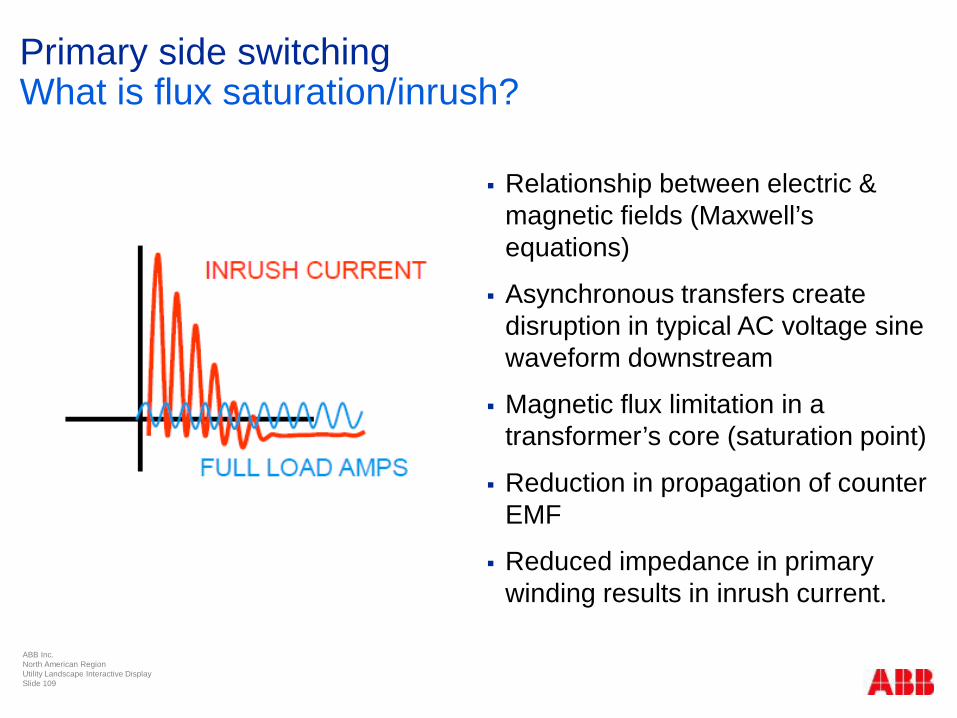
Primary side switching What is flux saturation/inrush?
ABB Inc. North American Region Utility Landscape Interactive Display Slide 109
Relationship between electric & magnetic fields (Maxwell’s equations)
Asynchronous transfers create disruption in typical AC voltage sine waveform downstream
Magnetic flux limitation in a transformer’s core (saturation point)
Reduction in propagation of counter EMF
Reduced impedance in primary winding results in inrush current.
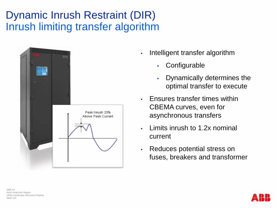
Dynamic Inrush Restraint (DIR)
Inrush limiting transfer algorithm
ABB Inc. North American Region Utility Landscape Interactive Display Slide 110
• Intelligent transfer algorithm
• Configurable
• Dynamically determines the optimal transfer to execute
• Ensures transfer times within CBEMA curves, even for asynchronous transfers
• Limits inrush to 1.2x nominal current
• Reduces potential stress on fuses, breakers and transformer

Dynamic Inrush Restraint (DIR) Real Time Flux Control™
ABB Inc. North American Region Utility Landscape Interactive Display Slide 111
Computes flux trapped in the transformer in real time (every 130.2usec)
Controls the amount of flux induced in the core
Continuously determines the optimal SCR firing angle for each phase
Compatible with all types of transformers
Addresses inrush in all three phases
Δ Y
Main DSP
DSP 1
SOURCE 2SOURCE 1
DSP 2

Real Time Flux Control™ for DIR 180° loss of source transfer
Sense + Transfer Time

Real Time Flux Control™ for DIR 60° loss of source transfer
ABB Inc. North American Region Utility Landscape Interactive Display Slide 113
Sense + Transfer Time

Real Time Flux Control™ for DIR Configurability
ABB Inc. North American Region Utility Landscape Interactive Display Slide 114
4.00
6.00
8.00
10.00
12.00
14.00
16.00
-180 -120 -60 0 60 120 180
Tran
sfer
+ S
ense
Tim
e (M
SEC
)
Angle (DEG)
PQ TRANSFERS Measured Expected
Super Transfer Area Not used if DIR LIMITED is enabled

Best method for preventing flux saturation? Real Time Flux Control™ for DIR
ABB Inc. North American Region Utility Landscape Interactive Display Slide 115
Reduces stress on upstream infrastructure
Sense + transfer times under 16ms, regardless of phase shift
User configurable:
STS determines the optimal transfer algorithm to execute
On demand – no need to turn on or off
Limits inrush to 1.2x nominal current
Eliminates possible UPS overload or going to bypass
IEC 61850 GOOSE enabled innovations
Don Elliott
Digital switchgear and IEC 61850 Increase speed, reliability and more
Agenda
Industry requirements
Definition of digital switchgear
Key digital switchgear components
Digital switchgear benefits
IEC 61850 with GOOSE
Security

Distribution networks are getting more complex Increasing demands on MV switchgear
Be “smart”
Be easy
Be flexible
Be safe
Be simple
Be environmental friendly Be future proof
Be on time Be reliable
Be efficient
Presenter
Presentation Notes
Distribution networks have changed in the last years and are getting more complex. The complexity comes from distributed energy resources or renewable energy sources which are installed in the network. Energy demands in the network have increased, reliability and safety levels were extended to fulfill higher standards for safer operation of equipment. Medium Voltage (MV) switchgear distributing the electrical energy is a very important element of electrical networks, which provide an uninterrupted supply of electrical energy to the whole network. With the new requirements and challenges for distribution networks, MV switchgear has a more important role as part of the grid than ever before. Evolution in distribution networks demands MV switchgear that is more efficient, safe, smart, reliable, environmentally friendly, and easy to engineer, install and operate.

Digital Switchgear New concept for MV switchgear
Digital switchgear is not only new products, it is a new concept in protection, control, automation
61850

Digital switchgear Advanced measurement solution
Presenter
Presentation Notes
Optimized design of sensors – refers to the new design itself and the placement of the sensor in the panel Additional benefits of sensors – low PD (partial discharge) value, extremely low energy consumption (few nano-Watts)

Rogowski coil sensor Us=150 mV for 50 Hz Us=180 mV for 60 Hz
Proven technology which brings many benefits in various applications
Output voltage is proportional to the derivative of primary current
Output voltage is integrated by IED
Accuracy up to class 0.5
Complies with IEC 60044-8
Digital switchgear Current sensors
IP
US
dttdi
Mtu ps
)()( =
No saturation!

Digital switchgear Current sensors

Digital switchgear Current sensors – combined accuracy class 0.5/5P630
Presenter
Presentation Notes
Current sensors, thanks to their linear characteristic, guarantee wide range of primary current. The sensor standard, IEC 60044-8, defines accuracy characteristic as combination of metering and protection class into one. Thus, current sensors transmit currents from couple of Amps up to short circuit, therefore accuracy class is defined as 5P630, where 630 is not an error but a real number calculated out of maximal current to be transmitted via sensor to secondary side. Moreover accuracy of sensor is improved by utilizing correction factors in the protection relays.
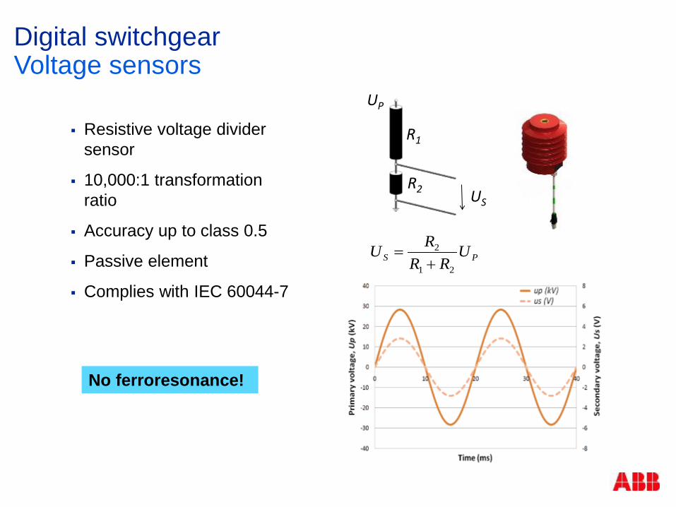
Digital switchgear Voltage sensors
Resistive voltage divider sensor
10,000:1 transformation ratio
Accuracy up to class 0.5
Passive element
Complies with IEC 60044-7
US
UP
PS URR
RU21
2
+=
No ferroresonance!
R2
R1
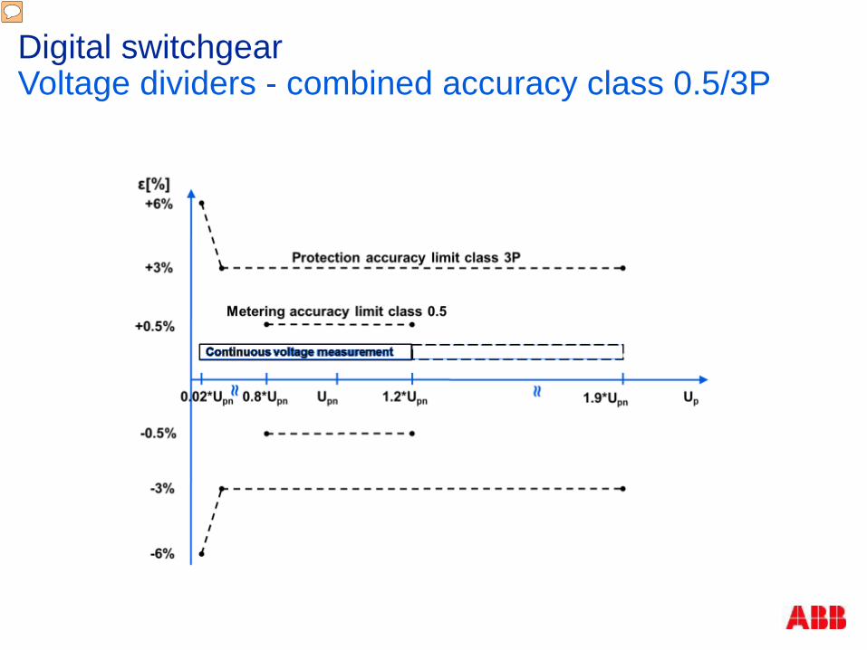
Digital switchgear Voltage dividers - combined accuracy class 0.5/3P
Presenter
Presentation Notes
For voltage sensors, sensor standard IEC 60044-7, defines the accuracy class combining metering and protection class into one. Thus voltage sensors have accuracy class of 0.5.

Digital switchgear
Sensors - simple secondary connection to IED
Current sensor
Voltage sensor
IED (Intelligent Electronic Device)
Adapter
Almost no analog wiring in the switchgear – increases reliability
IED must have LEA (Low Energy Analog) inputs compatible with the Rogowski coil and RVD sensors.
Presenter
Presentation Notes
Sensors provide error free connection. Relion protection relays have combined sensor input, which combines current and voltage measurement in one RJ45 port. Protection relay has 3 combined sensor inputs per an analog input board. Sensor secondary shielded cable can be connected either directly to the protection relay, if only current or only voltage measurement is needed, as visible on slide. Utilization of IEC 61850 and Sensors in UniGear Digital allow us to be more flexible. Sensors bring flexibility thanks to their wide range of application, IEC 61850 thanks to GOOSE and Process Bus. Process Bus, IEC 61850-9-2, defines sharing of analog values between the protection relays e.g. voltage measurement, and even further reduces number of interconnecting wires.

Digital switchgear Future proof solution based on IEC 61850
Based on worldwide accepted standard ensuring long term sustainability
Ready to be connected to remote control systems
Available IEC 61850 features: vertical communication horizontal GOOSE
communication process bus
61850
Presenter
Presentation Notes
IEC 61850 released in 2004 – it is proven standard, worldwide accepted. Process bus as an option for sharing the voltage signal measured by voltage sensors within the substation. If the Process bus is not accepted the voltage sensors can be installed in each panel.

Capacity Integrated voltage measurement
within insulator reduces space requirements
Current sensor located in monoblock reduces space requirements
Safety Low energy analogue sensors Fewer wires to install, commission,
maintain Quality
Better sensor accuracy and range of measurement improves protection & control
Digital switchgear Technology for better switchgear
Presenter
Presentation Notes
Optimized design of sensors – refers to the new design itself and the placement of the sensor in the panel (in UG ZS1 between the shutter and spout) Additional benefits of sensors – low PD (partial discharge) value, extremely low energy consumption (few nano Watts), just few variants covering ratings up to 4000A / 50kA, available on stock

Efficiency
Lower operating cost (sensors consume less power)
Later configuration during manufacture (fewer wires to design and install)
Sustainability
Universal standards (IEC61850) enable future system expansion
Lower environmental impact during operation
Reliability
Fewer parts to fail
Digital switchgear Technology for better switchgear
Presenter
Presentation Notes
Optimized design of sensors – refers to the new design itself and the placement of the sensor in the panel (in UG ZS1 between the shutter and spout) Additional benefits of sensors – low PD (partial discharge) value, extremely low energy consumption (few nano Watts), just few variants covering ratings up to 4000A / 50kA, available on stock

Digital switchgear Technology for better switchgear
Digital solution:
Changing loads does not require changes in hardware like instrument transformers
Saves time and money during planning and execution
Improved accuracy and range of current and voltage measurement for metering, protection and control
Meets latest cybersecurity and communication performance standards
Manufacturer independant communication standard
Ready for easy SCADA integration
Presenter
Presentation Notes
Optimized design of sensors – refers to the new design itself and the placement of the sensor in the panel (in UG ZS1 between the shutter and spout) Additional benefits of sensors – low PD (partial discharge) value, extremely low energy consumption (few nano Watts), just few variants covering ratings up to 4000A / 50kA, available on stock

Digital switchgear Technology for better switchgear
Reduced losses during operation
Lower sensor losses
Saving potential of up to 250 MWh over 30 years (sample switchgear with 14 frames & 42 CTs)
Improved equipment reliability
Fewer live parts, fewer failure opportunities reducing outage potential and troubleshooting costs
Solution that requires less space
Complete transformer compartments eliminated
Frame count can be reduced
Reduced space means lower installation costs
Presenter
Presentation Notes
Optimized design of sensors – refers to the new design itself and the placement of the sensor in the panel (in UG ZS1 between the shutter and spout) Additional benefits of sensors – low PD (partial discharge) value, extremely low energy consumption (few nano Watts), just few variants covering ratings up to 4000A / 50kA, available on stock

Blue tooth configuration “Speaks” 8 industrial control networking languages including IEC61850
Real time load management
Available ATS control
Reduces switchgear size and material costs by up to 25%
Helps to prevent power failures
Power Quality Functions
Thermal Sensors
Contact Wear Algorithms
Digital Switchgear Low Voltage Switchgear Devices
Month DD, YYYY
Presenter
Presentation Notes
Intelligent devices lead to intelligent systems Pushing the intelligence to the component may remove control layers, allowing simplicity Traditionally, breaker is dumb, switchgear has PMS components, “speaking” to a BMS, which then “speaks” to a DCIM system, now the breaker is intelligent and can directly interface with the DCIM In the “hyperscale” industrial data center, the scale itself drives the need for simplicity in the control packages and interfaces (foreshadow the MNS Up and decrease in commissioning time as well as GOOSE/IEC61850 “open, flat, communications”)

Digital switchgear Sensors and IEC 61850 communication

Digital switchgear IEC 61850 communication and Goose
Solution does not require extra frames for instrumentation Greatly reduced wiring
…
Communication Network (Ethernet)
…
Horizontal GOOSE communication Number of interconnections is equal to number of devices
Conventional approach Wiring between devices must be done individually per signal
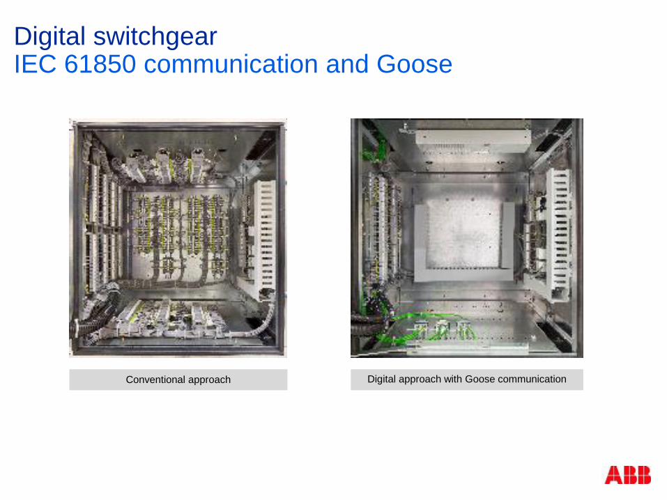
Digital switchgear IEC 61850 communication and Goose
Digital approach with Goose communication Conventional approach

Digital switchgear IEC 61850 Security
New innovations in automation and connectivity have generated concerns regarding cyber security
Open IT standards such as IEC 61850 have built in cyber security mechanisms
Cyber security certification per IEC 624443
Security protocols per IEC 62351
Incorporating TC 57 series requirements
HMI’s (relays and control panels)
4 layers of security passwords
4 levels of access/administration
Security zones with built-in firewalls for complete system protection
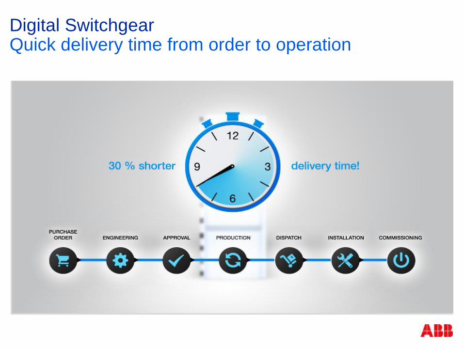
Digital Switchgear Quick delivery time from order to operation
Purchase Order
Dispatch
Engineering
Production
Installation

Digital switchgear
This solution eliminates the trouble of defining details like CT/VT data...
For all applications/relays?
No, but for nearly all of them! Reduced engineering and easier configuration selection. Reduces project administration and engineering costs
This solution supports minimized time to receive the project documentation
CT/VT data not required
Flexible towards last-minute changes
Most changes are simply realizable within the IED’s logic, only minor changes in wiring and schematics (if any)
Quick delivery time from order to operation
Quick delivery time from order to operation

Digital switchgear Lower environmental impact

Digital switchgear
Digital switchgear:
Solutions that use less material
Less steel, less copper, less epoxy, …
Solutions with reduced losses
Lower energy required to operate the gear
Digital switchgear can save a significant level of CO2
Lower environmental impact
Lower environmental impact

Distribution networks are getting more complex Increasing demands on MV switchgear
Be “smart”
Be easy
Be flexible
Be safe
Be simple
Be environmental friendly Be future proof
Be on time Be reliable
Be efficient
Space & weight saving
Minimal variation > Low inventory needed
Significant energy savings
Measurement devices with high accuracy over an extended range. Can deal with varying load flows. Simplified wiring
Possibility of late customization
Digital switchgear is the solution.

Substation Design Considerations Data Center Expert Day
ABB Power Systems – Grid Integration

Factors to Consider in Selecting Substation Configurations
© ABB Group
Month DD, Year
| Slide 143
Substation Type & Configuration (Power Generation, Transmission, or Distribution)
First Costs vs. Cost of Power Supply Instability
Substation Voltage & Power Rating
Physical Size vs. Real Estate Availability & Cost
Reliability, Future Expansion and Related Cost
Complexity of Protection Scheme
Technology used – AIS, GIS, hybrid
Indoor vs. Outdoor
Operation & Maintenance Impact

Substation Configurations
© ABB Group
Month DD, Year
| Slide 144
Substation configuration or Bus switching scheme is the circuit adopted for substation considering the following main criteria:
System reliability
Operational flexibility
Ease of Operation & Maintenance
Simplicity of Protection system
Ease of Expansion
Availability of Land
Initial Cost
Cost of Power Interruptions
Others Factors…

Typical Datacenter Substation Configurations
© ABB Group
Month DD, Year
| Slide 145
Collector Bus
“H” configuration
Main and Transfer Bus
Double Bus, Single Breaker
Ring Bus
Breaker and a Half
Double Bus, Double Breaker

Collector Bus Configuration
© ABB Group
Month DD, Year
| Slide 146
Lowest cost
Simple operation
Simple relaying protection scheme
Lowest reliability
Bus faults and breaker failures result in substation shutdown
Difficult to maintain (outage required)
Difficult to expand (outage required)
Features

Collector Bus Configuration
© ABB Group
Month DD, Year
| Slide 147
93,000 FT2

“H” Bus Configuration (simplified option)
© ABB Group
Month DD, Year
| Slide 148
Simple system Ease of Operation Single level bus layout
Very simple Control & Protection philosophy
Large saving in space Some redundancy Fault on one feeder will trip two
breakers.
Features

“H” Bus Configuration
© ABB Group
Month DD, Year
| Slide 149
81,225 FT2
Line Fault

“H” Bus Configuration
© ABB Group
Month DD, Year
| Slide 150
81,225 FT2
Bus Fault

Double-Bus Single-Breaker (DBSB) Configuration
Application
Normally this is used for most industrial stations and some time small power evacuation system
Features
Simpler system
Better availability as additional bus is provided
More reliable compare to Single Bus configuration
Bus fault on one Bus will not effect the other Bus.

Double-Bus Single-Breaker Configuration
© ABB Group
Month DD, Year
| Slide 152
133,200 FT2

Breaker-And-A-Half (BAAH) Configuration
Application
Mostly this configuration is adopted where high reliability is required
Power evacuation station for big power plant
Interconnecting transmission substations with 420/245kV level
Features
Very high reliability
Costly because of increase number of Circuit Breaker
Complex Control & Protection philosophy

Breaker-And-A-Half Configuration – Air Insulated
© ABB Group
Month DD, Year
| Slide 154
101,250 FT2

Breaker-And-A-Half Configuration – Gas Insulated
© ABB Group
Month DD, Year
| Slide 155
55,125 FT2

Transmission Grid Connections Urban, suburban & rural environments
GL “Pat” Ervin, ABB Power Grids, Compact Substation Business Development Manager

Topics of discussion Compact high voltage switching technology overview
Traditional air insulated substation (AIS) and compact gas insulated substation (GIS) comparisons
Substation physical security: build a small energy bunker instead of a large fortress
AIS to GIS conversion opportunities
GIS benefits discussion- all substations are GIS candidates

HV Switching Technology Hierarchy lo
w
no
Functional integration
Encapsulation partial full
med
ium
hi
gh
DTB Circuit Breaker Current Transformer
Hybrid Modules Circuit Breaker Current Transformer Voltage Transformer Disconnector Earthing Switch
GIS Circuit Breaker Current Transformer Voltage Transformer Disconnector Earthing Switch Busbar / Busducts
LTB Circuit Breaker
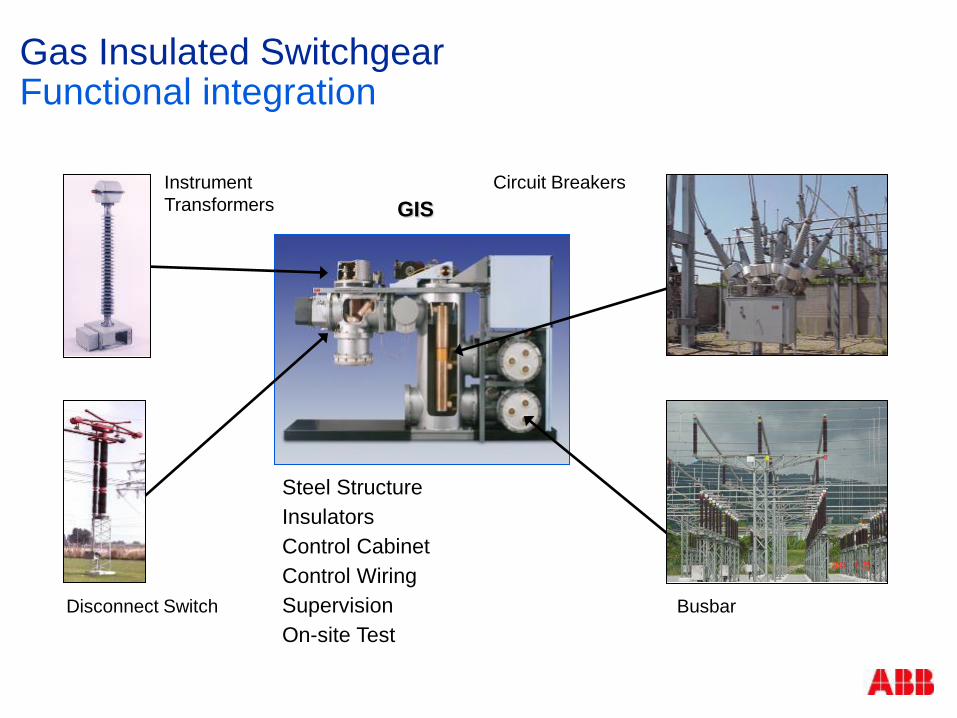
Circuit Breakers Instrument Transformers
Busbar Disconnect Switch
GIS
Steel Structure Insulators Control Cabinet Control Wiring Supervision On-site Test
Gas Insulated Switchgear Functional integration

Canopies – equipment almost independent from environment Building of all types – prefab metal to underground Increased reliability Use under difficult climatic conditions Easy planning of outages for service and maintenance
Compact Gas Insulated Substation Indoor or outdoor applications
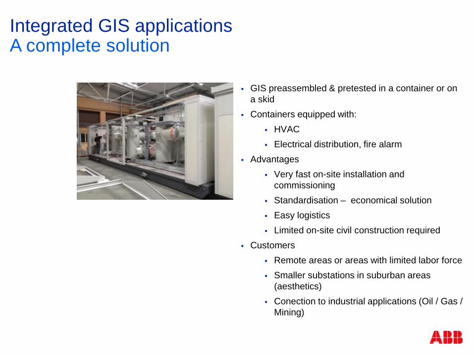
GIS preassembled & pretested in a container or on a skid
Containers equipped with: HVAC Electrical distribution, fire alarm
Advantages Very fast on-site installation and
commissioning Standardisation – economical solution Easy logistics Limited on-site civil construction required
Customers Remote areas or areas with limited labor force Smaller substations in suburban areas
(aesthetics) Conection to industrial applications (Oil / Gas /
Mining)
Integrated GIS applications A complete solution

Increased Grid Reliability Due to GIS
Enclosed high voltage components
Elevated substations for flood and wetland areas, special soil conditions or in existing substations
Seismically proofed equipment
Use of HV power cable in combination with GIS
Weather independent O&M
High Voltage Gas Insulated Substations Substation reliability
Topics of discussion
Compact high voltage switching technology overview
Traditional air insulated substation (AIS) and compact gas insulated substation (GIS) comparisons
Substation physical security: build a small energy bunker instead of a large fortress
AIS to GIS conversion opportunities
GIS benefits discussion- all substations are GIS candidates

AIS- GIS Substation Comparison
AIS GIS

Example: 138kV 4 breaker ring configuration Single line diagram

Example: 138kV 4 breaker ring configuration Conventional AIS substation layout
AIS
4 breaker ring
180 ft x 150 ft
27,000 sqft

GIS-AIS 138kV switchyard comparison
Traditional 27,000 sq. ft. or 0.6 acre
Compact 840 sq. ft. (40ft x 21ft) or 0.02 acre
Compact Switching
Container

Topics of discussion Compact high voltage switching technology overview
Traditional air insulated substation (AIS) and compact gas insulated substation (GIS) comparisons
Substation physical security: build a small energy bunker instead of a large fortress
AIS to GIS conversion opportunities
GIS benefits discussion- all substations are GIS candidates

Build a small energy bunker NOT a large fortress

Large energy fortress using traditional air insulated switchgear
Exterior & interior 8-20’ walls and gating
Curved entry roadways
Forward looking radar
Anti drone capability
Mantraps
Extensive camera & lighting systems
Annual first responder training
Armed security guards
Easily identifiable

Barbaña Underground Substation, Spain 132 kV, 40 kA Single Busbar Configuration (3 CB) Transformer 132/20 kV, 15 MVA
Substation physical security Underground GIS substation

Substation physical security Underground GIS substation

High Voltage Gas Insulated substations Substation security – GIS Heidelberg / Germany

Topics of discussion
Compact high voltage switching technology overview
Traditional air insulated substation (AIS) and compact gas insulated substation (GIS) comparisons
Substation physical security: build a small energy bunker instead of a large fortress
AIS to GIS conversion opportunities
GIS benefits discussion- all substations are GIS candidates

Downtown residential planned AIS substation
Utility purchased 125’ x 150’ lot (18,750 sq ft) for $2.4 million
Traditional Substation Compact Substation
Bank Building & Parking Garage

Utility purchased 90’ x 190’ lot (17,100 sq ft) for $2.3 million
Elementary School Hospital
Compact Substation
Traditional Substation Compact Substation
Downtown planned AIS substation

Topics of discussion
Compact high voltage switching technology overview
Traditional air insulated substation (AIS) and compact gas insulated substation (GIS) comparisons
Substation physical security: build a small energy bunker instead of a large fortress
AIS to GIS conversion opportunities
GIS benefits discussion- all substations are GIS candidates

GIS benefits
Small footprint: can install inside a new or existing building or enclosed skid
Lower real estate cost Less site preparation Reduced construction time: possible “plug & play” options Aesthetically pleasing: limited or no “wirescape” Substation security: build a small energy bunker not a large costly
fortress Price competitive Mitigate storm damage & climatic impacts Easier to permit Locatable next to load centers 15 times the reliability of AIS

Modular Systems E-Houses & Product Packaging Solutions
November 14, 2016

Agenda
2-Dec-16 | Slide 181 © ABB
• Introduction Types of Packages Value Summary

Introduction
2-Dec-16 | Slide 182 © ABB
Package: Multi-product Packaging
implementation, either as loose equipment or in a containerized solution (E-house).
With a wide variety of electrical products available, product packaging offers a seamlessly integrated solution.

Introduction Responsibility
2-Dec-16 | Slide 183 © ABB
Ownership of the integration of electrical products, systems, and services by providing one point of contact for proposal engineering and project
management through the complete project lifecycle
Introduction Project Team
2-Dec-16 | Slide 184 © ABB
Packaging Team includes:
Marketing/Proposal Engineers
Project Engineers
Project Managers
Controller/Analyst
Document Control

Types of Packages E-House
2-Dec-16 | Slide 185 © ABB

Types of Packages Loose Equipment/Packaged Products
2-Dec-16 | Slide 186 © ABB
Assortment of several kinds of equipment from different factories
Coordination of equipment delivery based on site requirements
Applications: additional capacity, equipment for existing structures, additional requirements for indoor and outdoor equipment
Value
2-Dec-16 | Slide 187 © ABB
Single commercial contract
Alleviates customer resources
Estimators
Purchasers
Legal
Project managers
Engineers
Risk mitigation
Ease of communication
Interface engineering
Scheduling/delivery coordination
Payment milestones based on entire package
Reduced site work
Safer
Less expensive
One set of warranty terms
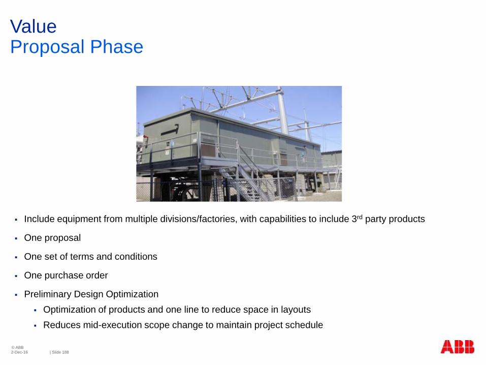
Value Proposal Phase
2-Dec-16 | Slide 188 © ABB
Include equipment from multiple divisions/factories, with capabilities to include 3rd party products
One proposal
One set of terms and conditions
One purchase order
Preliminary Design Optimization Optimization of products and one line to reduce space in layouts Reduces mid-execution scope change to maintain project schedule

Value Preliminary Design Optimization Example
2-Dec-16 | Slide 189 © ABB
Value Project Execution Phase
2-Dec-16 | Slide 190 © ABB
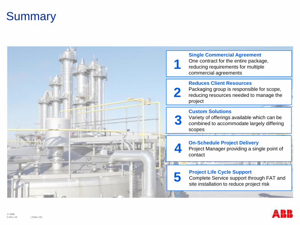
Summary
2-Dec-16 | Slide 191 © ABB
Perth
Melbourne
Brisbane
Custom Solutions Variety of offerings available which can be combined to accommodate largely differing scopes
On-Schedule Project Delivery Project Manager providing a single point of contact
Single Commercial Agreement One contract for the entire package, reducing requirements for multiple commercial agreements
Reduces Client Resources Packaging group is responsible for scope, reducing resources needed to manage the project
1
2
Project Life Cycle Support Complete Service support through FAT and site installation to reduce project risk
5
3
4