Data Communications TDC 362 / TDC 460 Circuit Switching and Packet Switching 1.
71
Data Communications TDC 362 / TDC 460 Circuit Switching and Packet Switching 1
-
date post
19-Dec-2015 -
Category
Documents
-
view
234 -
download
6
Transcript of Data Communications TDC 362 / TDC 460 Circuit Switching and Packet Switching 1.

Data CommunicationsTDC 362 / TDC 460
Circuit Switching and Packet Switching
1

8.1 Circuit Switching8.1 Circuit Switching
Space-Division Switch
Time-Division Switch
TDM Bus
Combinations
2

Figure 8.1 Circuit-switched network
3

Figure 8.2 A circuit switch
4

Blocking or Non-blocking
BlockingA network is unable to connect stations
because all paths are in useA blocking network allows thisUsed on voice systems
Short duration calls
Non-blockingPermits all stations to connect (in pairs) at onceUsed for some data connections
5

Figure 8.4 Crossbar switch
6
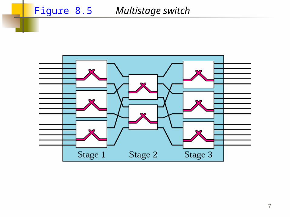
Figure 8.5 Multistage switch
7

Figure 8.6 Switching path
8

Three Stage Switch
9

Figure 8.7 Time-division multiplexing, without and with a Time-slot interchange
10

Figure 8.8 Time-slot interchange
11

Figure 8.9 TDM bus
12

Figure 8.10 TST (Time-space-time) switch
13

Circuit-Switched Routing
Many connections will need paths through more than one switch
Need to find a routeEfficiencyResilience
Public telephone switches are a tree structureStatic routing uses the same approach all the time
Dynamic routing allows for changes in routing depending on trafficUses a peer structure for nodes
14

Alternate Routing
Possible routes between end offices predefined
Originating switch selects appropriate route
Routes listed in preference orderDifferent sets of routes may be used at
different times
15

Alternate Routing Diagram
16

Control Signaling Functions
Audible communication with subscriberTransmission of dialed numberCall can not be completed indicationCall ended indicationSignal to ring phoneBilling infoEquipment and trunk status infoDiagnostic infoControl of specialist equipment
17

Control Signals
18

Location of Signaling
Subscriber to networkDepends on subscriber device and switch
Within networkManagement of subscriber calls and networkore complex
19

In Channel Signaling
Use same channel for signaling and callRequires no additional transmission facilities
InbandUses same frequencies as voice signalCan go anywhere a voice signal canImpossible to set up a call on a faulty speech
path
Out-of-bandVoice signals do not use full 4kHz bandwidthNarrow signal band within 4kHz used for controlCan be sent whether or not voice signals are
presentNeed extra electronicsSlower signal rate (narrow bandwidth)
20

Drawbacks of In Channel Signaling
Limited transfer rateDelay between entering address (dialing)
and connectionOvercome by use of common channel
signaling
21

Common Channel SignalingControl signals carried over paths
independent of voice channelOne control signal channel can carry signals
for a number of subscriber channelsCommon control channel for these subscriber
linesAssociated Mode
Common channel closely tracks interswitch trunks
Disassociated ModeAdditional nodes (signal transfer points)Effectively two separate networks
22

Common vs. In Channel Signaling
23

Signaling Modes
24

Signaling System Number 7
SS7Most widely used common channel
signaling schemeInternationally standardized and general
purpose
25

SS7
SS7 network and protocol used for:Basic call setup, management, tear downWireless services such as PCS, roaming,
authenticationToll free and toll (900) wireline servicesEnhanced features such as call forwarding,
caller ID, 3-way callingEfficient and secure worldwide
telecommunications
26

SS7
SS7 messages are exchanged between central offices and specialized databases via signal transfer points (packet switches).
Control planeResponsible for establishing and managing
connections
Information planeOnce a connection is set up, info is transferred
in the information plane
27

SS7 Signaling Network Elements
Service switching point (SSP)SSPs enable central offices to communicate with
SS7 databases (the user entry point into SS7)
Signal transfer point (STP)A signaling point (packet switch) capable of
routing control messages
Service control point (SCP)SCPs contain databases with call routing
instructions
28

SS7
SSP
SSP
SSP
STP
STP
SCP
SCP
CentralOffice
CentralOffice
CentralOffice
29
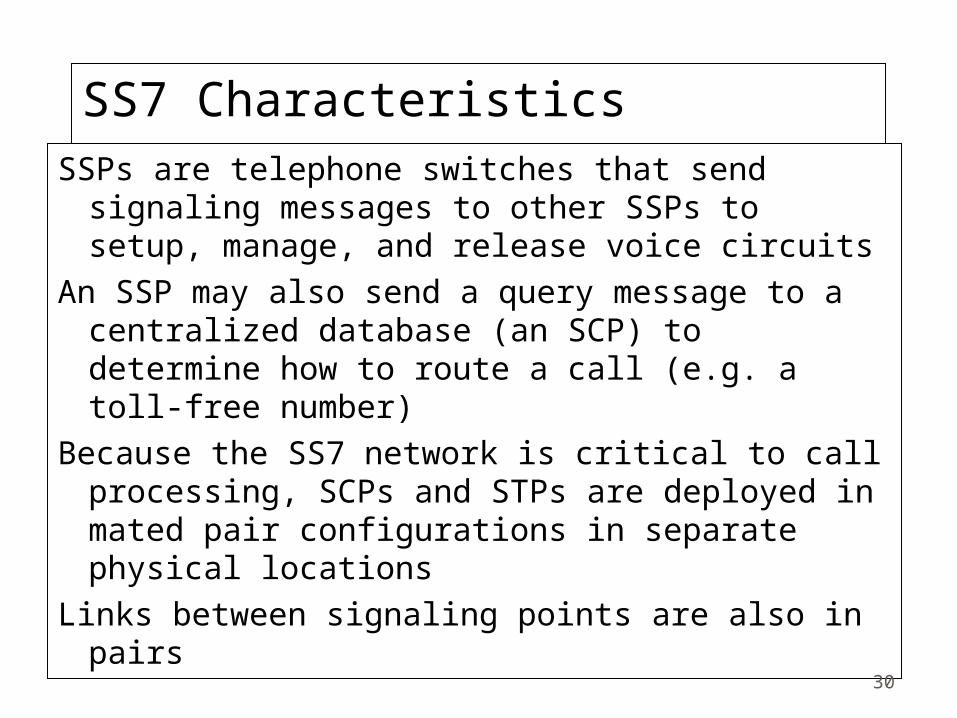
SS7 CharacteristicsSSPs are telephone switches that send
signaling messages to other SSPs to setup, manage, and release voice circuits
An SSP may also send a query message to a centralized database (an SCP) to determine how to route a call (e.g. a toll-free number)
Because the SS7 network is critical to call processing, SCPs and STPs are deployed in mated pair configurations in separate physical locations
Links between signaling points are also in pairs 30

Packet Switching PrinciplesCircuit switching designed for voice
Resources dedicated to a particular callMuch of the time a data connection is idleData rate is fixed
Both ends must operate at the same rate
What if we don’t want a dedicated call, or the data rate is bursty? You want packet switching!
31

Basic OperationData transmitted in small packets
Typically 1000 bytesLonger messages split into series of packetsEach packet contains a portion of user data plus
some control info (such as addressing info or packet type)
Packets are received, stored briefly (buffered) and passed on to the next nodeStore and forward (only ATM does not do this)
32

AdvantagesLine efficiency
Single node to node link can be shared by many packets over time
Packets queued and transmitted as fast as possible
Data rate conversionEach station connects to the local node at its own
speedNodes buffer data if required to equalize rates
Packets are accepted even when network is busyDelivery may slow down
Priorities can be used
33
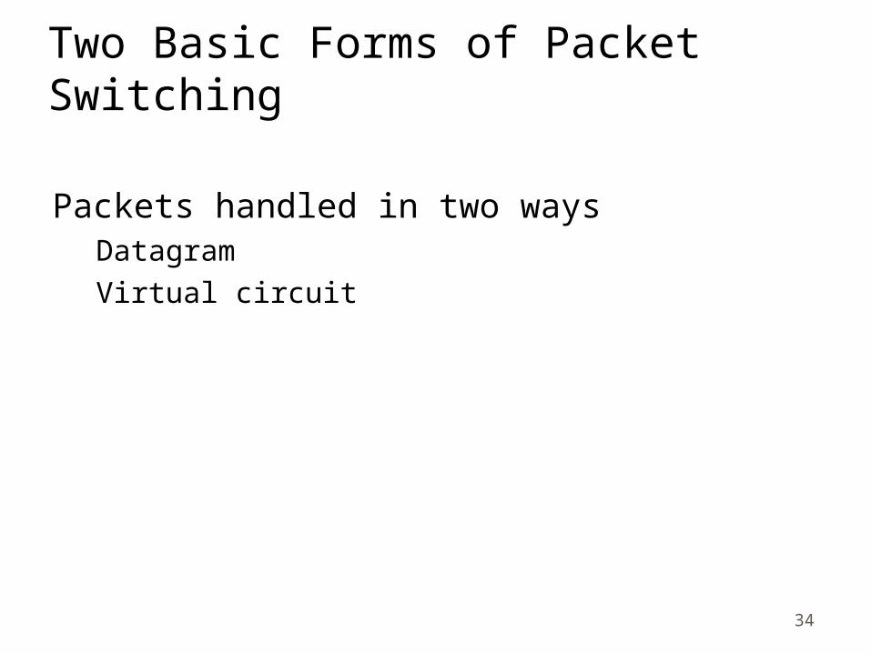
Two Basic Forms of Packet Switching
Packets handled in two waysDatagramVirtual circuit
34

DatagramEach packet treated independentlyPackets can take any practical routePackets may arrive out of orderPackets may get lost or delayedUp to receiver to re-order packets and
recover from missing packets
35

Virtual CircuitPreplanned route established before any
packets sentCall request and call accept packets
establish connection (handshake)Each packet contains a virtual circuit
identifier instead of destination addressNo routing decisions required for each
packetClear request to drop circuitNot a dedicated path
36
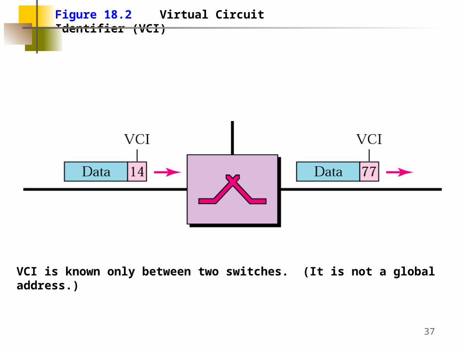
Figure 18.2 Virtual Circuit Identifier (VCI)
VCI is known only between two switches. (It is not a globaladdress.)
37

Figure 18.4 Switch and table
38

Figure 18.5 Source-to-destination data transfer
39

S(witched)VC vs. P(ermanent)VC setup
A virtual circuit can be either switched or permanent.
If permanent, an outgoing VCI is given to the source, and an incoming VCI is given to the destination.
The source always uses this VCI to send frames tothis particular destination.
The destination knows that the frame is coming fromthat particular source if the frame carries thecorresponding incoming VCI.
If a duplex connection is needed, two virtual circuitsare established.
40

S(witched)VC vs. P(ermanent)VC setup
A PVC has several drawbacks:
1. Always connected, so always paying
2. Connection is between two parties only. If you need a connection to another point, youneed another PVC.
Don’t like these disadvantages? Use an SVC.
41

Figure 18.6 SVC setup request
1 - Setup frame sent from A to Switch I.Note how the Outgoing VCI is not yet known.
42

Figure 18.7 SVC setup acknowledgment
As the acknowledgment frame goes back, the VCI numberis placed into the Outgoing VCI entry in each table.
43

Virtual Circuits vs DatagramVirtual circuits
Network can provide sequencing and error controlPackets are forwarded more quickly
No routing decisions to make
Less reliableLoss of a node looses all circuits through that node
DatagramNo call setup phase
Better if few packets
More flexibleRouting can be used to avoid congested parts of
the network
44

Packet Size
45

Event Timing
46

RoutingComplex, crucial aspect of packet switched
networksCharacteristics required
CorrectnessSimplicityRobustnessStabilityFairnessOptimalityEfficiency
47

Performance CriteriaUsed for selection of routeMinimum hopLeast cost
Dijkstra’s algorithm most commonFinds the least cost path from one starting node
to all other nodesAlgorithm can be repeated for each starting
node
48

Dijkstra’s Least Cost Example
49

Dijkstra’s Least Cost Example
50

Decision Time and PlaceTime
Packet or virtual circuit basis
PlaceDistributed
Made by each node
Centralized - deadSource - dead
51

Basic Routing StrategiesAdaptive versus Fixed (dead?)
Distributed versus Centralized (dead?)
Flooding
52
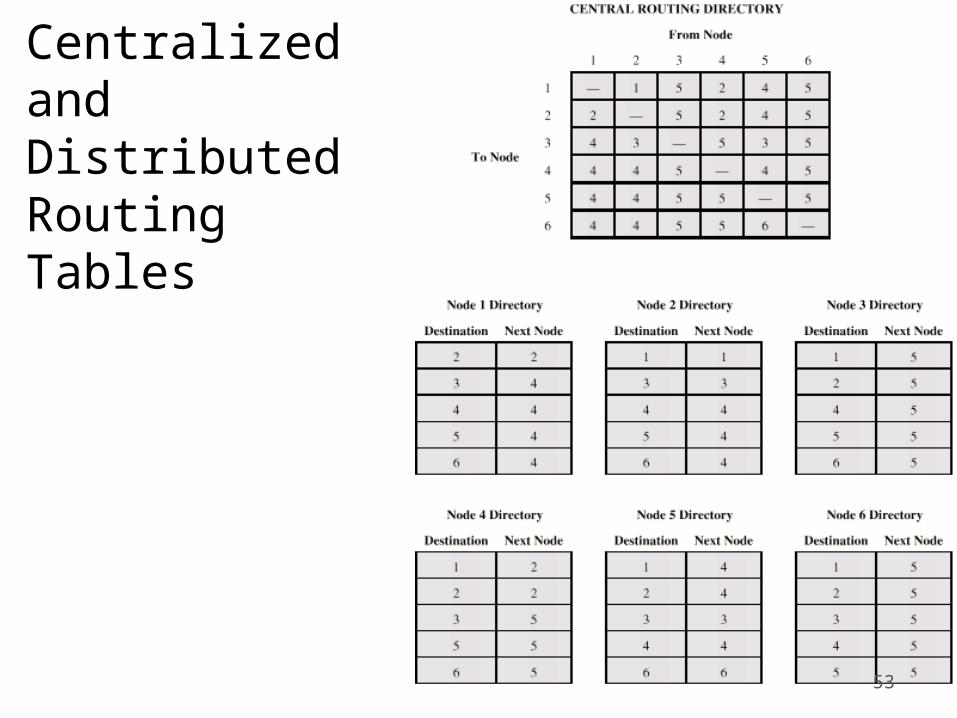
Centralizedand DistributedRoutingTables
53

FloodingNo network info requiredPacket sent by node to every neighborIncoming packets retransmitted on every link
except incoming linkEventually a number of copies will arrive at
destinationEach packet is uniquely numbered so duplicates
can be discardedNodes can remember packets already forwarded to
keep network load in boundsCan include a hop count in packets
54

Flooding Example
55
Properties of FloodingAll possible routes are tried
Very robust
At least one packet will have taken minimum hop count routeCan be used to set up virtual circuit
All nodes are visitedUseful to distribute information (e.g. routing)
56

Adaptive RoutingUsed by almost all packet switching networksRouting decisions change as conditions on the
network changeFailureCongestion
Requires info about networkDecisions more complexTradeoff between quality of network info and
overheadReacting too quickly can cause oscillationReacts too slow to be relevant
57

Adaptive Routing - AdvantagesImproved performanceAid congestion controlComplex system
May not realize theoretical benefits
58

Where does routing info come from?
Local (isolated)Route to outgoing link with shortest queueCan include bias for each destinationRarely used - do not make use of easily
available info
Adjacent (neighbor) nodes onlyAll nodes in network
59

Chapter 21
Unicast Routing Overview:Routing Protocols
(Details in TDC 365/463)
60

Figure 21.1 Unicasting
In unicast routing, the router forwards the received packet through only one of its ports.
Three basic unicast routing protocols: RIP, OSPF, BGP 61

Figure 21.3 Autonomous systems
R1, R2, R3 and R4 use an interior and exterior routingprotocol. The other routers use only an interior protocol.RIP and OSPF are interior, BGP is exterior.
62

RIP
RIP (Routing Information Protocol) is an interior routingProtocol based on distance vector routing which uses theBellman-Ford algorithm.
Each router shares its routing knowledge with its neighbors,every 30 seconds.
This shared information is used to update a router’s routingtable. An entry in the routing table consists of the destinationnetwork address, the shortest distance to reach the destination in hop count, and the next router to which thepacket should be delivered. (see next slide)
63

Table 21.1 Table 21.1 A distance vector routing tableA distance vector routing table
DestinationHop
CountNext
RouterOther information
163.5.0.0 7 172.6.23.4
197.5.13.0 5 176.3.6.17
189.45.0.0 4 200.5.1.6
115.0.0.0 6 131.4.7.19
64

Receive: a response RIP message1. Add one hop to the hop count for each advertised destination.2. Repeat the following steps for each advertised destination: 1. If (destination not in the routing table) 1. Add the advertised information to the table. 2. Else 1. If (next-hop field is the same) 1. Replace entry in the table with the advertised one. 2. Else 1. If (advertised hop count smaller than one in the table) 1. Replace entry in the routing table.3. Return.
RIP Updating AlgorithmRIP Updating Algorithm
65

Figure 21.4 Example of updating a routing table
66

OSPF
OSPF (Open Shortest Path First) protocol is another interiorrouting protocol for autonomous systems.
Special routers called autonomous system boundary routersare responsible for dissipating information about other autonomous systems into the current system.
To handle routing efficiently and in a timely manner, OSPFdivides an autonomous system into areas.
67

Figure 21.7 Areas in an autonomous system
68
OSPF
In OSPF, each router sends the state of its neighborhood toevery other router in the area. It does this by flooding.
The state of its neighborhood is only shared when there isnew information. This generates much less traffic than doesdistance vector routing (RIP).
OSPF keeps information on its links (the connection betweentwo routers). There are 4 types of links: point-to-point, transient, stub, and virtual.
To share information about their neighbors, each entitydistributes link state advertisements (LSAs).
69

OSPF
There are 5 different types of LSAs: router link, network link,summary link to network, summary link to AS boundaryrouter, and external link.
Every router in an area receives the router link LSAs and network link LSAs from every other router and forms a link state database.
Dijkstra’s least cost algorithm is applied to this link statedatabase to create the routing table. The routing table showsthe cost of reaching each network in the area.
70

BGP
RIP and OSPF have shortcomings.
RIP (distance vector routing) is not always optimal becauseThe smallest hop count is not always the optimal route. Plus,bad news moves slowly.
OSPF (link state routing) has the shortcoming of a possiblyhuge routing table. To use link state routing for the wholeinternet would require each router to have a huge database.
What about BGP (Border Gateway Protocol)? It is an inter-autonomous system routing protocol and is based on a routingmethod called path vector routing.
71