Data Communications Introduction
287
Introduction to Data Communications Table of Contents 1. Introduction 12 2. Acknowledgem ents 12 3. Revision List 13 4. Data Communicatio ns 15 5. Why Telecommunic ations? 15 a. Voice Channels 15 b. Data Channels 16 6. Introduction to Networking 17 a. The Big Picture 17 1
description
Introduction to data communication networking
Transcript of Data Communications Introduction
Introduction to Data CommunicationsTable of Contents
1. Introduction 12
2. Acknowledgements 12
3. Revision List 13
4. Data Communications 15
5. Why Telecommunications? 15
a. Voice Channels 15
b. Data Channels 16
6. Introduction to Networking 17
a. The Big Picture 17
b. Telecommunications Components of The Big Picture 20
c. ISO OSI 20
7. Breaking The Big Picture up! 22
a. The Local Loop 22
b. LANs 23 c. MANs 24 d. WANs. 26
1
8. Trade Magazines 27
9. The Role of Telecommunications in Networking 29
a. LANs 29 b. MANs 29 c. WANs 30
10. Brief History of Networking 31
11. Data Communication Network 34
a. Performance 34 b. Consistency 34 c. Reliability, 35 d. Recovery 36 e. Security 36 f. Applications 36
g. Basic Components 38
12. Data Flow 40
13. Modems 43
a. Basic Definition 43
b. Digital Connection 43
c. Analog Connection 45
d. External/Internal Modems 45
e. Modem Types 47
f. Features of Modems 49
g. Modem Speeds / Standards 50
h. Transfer Rate versus PC Bus Speed 51
2
h. V.90 56 kbps Modems 51
14. Physical Connection 52
15. Transmission Media - Guided 53
a. Open Wire 53 b. Twisted Pair 55 c. Coaxial Cable 57 d. Optical Fibre 57
i. Optical Transmission Modes 59
ii. Step Index Mode 61
iii. Grade Index Mode 61
iv. Single Mode 61
v. Comparison of Optical Fibres 63
vi. Advantages of Optical Fibre 64
vii. Disadvantages of Optical Fibre 65
e. Media versus Bandwidth 65
16. Transmission Media - Unguided 65
a. RF Propagation 66
i. Ground Wave Propagation 66
ii. Ionospheric Propagation 67
iii. Line of Sight Propagation 67
b. Radio Frequencies 68
c. Microwave 69 d. Satellite 70 e. Iridium 72
3
Telecom System
17. RS-232D Serial Interface Standard
74
a. Mechanical Characteristics of the RS-232D 74
b. Electrical Characteristics of the RS-232D 74
c. Function of Each Signal 76
d. Subsets of Signals for Certain Applications 78
18. RS-232D Flow Control 80
a. Hardware Handshaking 81
b. Hardware Null Modems 88
c. Software Handshaking (Xon/Xoff) 89
d. Software Null Modem 89
e. Terminals & PCs 91
19. Timing 92
a. Asynchronous vs. Synchronous Transmission 93
20. Asynchronous Communications 95
a. Start/Stop bits 95 b. 7/8 Bit Codes 99 c. Parity Bits 101
21. Line Encoding 104
a. Unipolar Encoding 104
4
b. Polar Encoding 106
c. Bipolar Line Encoding 108
d. Manchester Line Encoding 108
22. Standard Digital Codes 110
a. EBCDIC - Extended Binary Coded Decimal Interchange Code110
b. ASCII - American Standard Code for Information Interchange 116
23. Voice Channel Communications 121
a. Voice Channel Specification 121
b. Voice Channel Constraints 122
c. Nyquist Theorem 123
24. Telephone Networks 125
a. POTS - Plain Old Telephone Set 125
b. Local Loops 129 c. Central Office 131
d. Hierarchical Phone Networks 131
25. Telephone Line Characteristics 135
a. Attenuation Distortion 135
b. Propagation Delay 137
c. Envelope 139
5
Delay Distortion
26. Line Impairments 140
a. Crosstalk 140
b. Echo or Signal Return 140
c. Frequency Shift 142
d. Non-Linear Distortion 142
e. Jitter: Amplitude and Phase 143
f. Transients: Impulse Noise, Gain Hits, Dropouts & Phase Hits
144
27. Modulation Techniques 147
a. AM - Amplitude Modulation 147
b. FM - Frequency Modulation 149
c. PM - Phase Modulation 149
28. Modem Modulation 151
a. FSK - Frequency Shift Keying 151
b. QPSK - Quadrature Phase Shift Keying 155
c. QAM - Quadrature Amplitude Modulation 157
29. AT Command Set 159
6
a. Basic AT commands 160
30. Multiplexing 161
a. FDM - Frequency Division Multiplexing 164
b. TDM - Time Division Multiplexing 166
c. STDM - Statistical Time Division Multiplexing 168
31. Telecommunication Multiplexing 168
a. FDM - Channel Groups 169
b. TDM - T1 Carrier System 169
32. Introduction to the ISO - OSI Model 172
a. OSI Model Explained 172
b. Layer 7 - Application Layer 172
c. Layer 6 - Presentation Layer 176
d. Layer 5 - Session Layer 177
e. Layer 4 - Transport Layer 177
f. Layer 3 - Network Layer 179
g. Layer 2 - Data Link Layer 179
h. Layer 1 - Physical Layer 180
i. Layer Specific 181
7
Communication
j. OSI Model Functional Drawing 183
33. Synchronous Transmission 185
a. Clocking: Self & Manchester Encoding 186
34. Basic Frame Structure 188
a. Preamble: Starting Delimiter/Alert Burst/Start of Header 188
b. Address Field(s): Source and/or Destination 188
c. Control Field 190
d. Data/Message and optional Pad 190
e. CRC/ Frame Check Sequence 190
f. End Frame Delimiter 190
35. Physical Layer 192
a. Asynchronous & Synchronous Communication 192
36. IEEE-802.3 Protocol 194
a. CSMA/CD (Carrier Sense Multiple Access/ Collision Detect) 194
b. IEEE 802.3 Ethernet Media Types 195
c. IEEE 802.3 10Base5 196
8

d. IEEE 802.3a 10Base2 200
e. IEEE 802.3i 10BaseT 203
f. MAC - Medium Access Control 206
g. Total Length of a MAC Frame 209
h. MAC Frame 211 i. Packet Sniffing 212
j. Packet Sniffing Block Diagram 216
37. IEEE 802.2 LLC - Logical Link Control Layer 217
a. Service Access Ports (SAPs) 219
b. Types of LLC Operation 220
c. Classes of LLC 224
d. LLC PDU Control Field Formats 224
38. Network Interface Cards 229
a. IRQs, DMAs and Base Addresses 230
b. Legacy 234
c. NIC Diagnostic Tools 236
d. Network Interface Card Drivers 238
i. NDIS Drivers 241 ii. ODI Drivers 243
iii. Packet Drivers 245
iv. Software Interrupts 245
9

39. Repeaters 247
a. Purpose of a Repeater
247
b. Repeater's OSI Operating Layer
249
c. Repeater's Segment to Segment Characteristics 249
d. Repeater Addressing: MAC Layer and Network Segment 251
40. Hubs 253
a. Purpose of Hubs 253
b. Hub's OSI Operating Layer 255
c. Hub's Segment to Segment Characteristics 255
d. Hub's Addressing 257
e. Half-Duplex & Full-Duplex Ethernet Hubs 257
f. Switching Hubs 258
41. Bridges 260
a. Bridge OSI Operating Layer 260
b. Purpose of a Bridge 260
c. Bridge Segment to Segment Characteristics 263
d. Bridge Methodologies 265
e. Reasons to use a Bridge 270
f. Bridge Addressing 270
10

g. Collapsed Backbones 270
42. Routers 272
a. Purpose of Routers 272
b. Router OSI Operating Layer 272
c. Router Segment to Segment Characteristics 274
d. Router Addressing 276
e. Routing Protocols 276
f. RIP - Routing Information Protocol 276
g. EGRP - Exterior Gateway Routing Protocol 279
h. OSPF - Open Shortest Path First 279
43. Brouters (Bridge/Routers) 281
44. Gateway 282
a. Gateway's OSI Operating Layer 282
b. Gateway Segment to Segment Characteristics 283
c. Gateway Addressing 283
45. Token Ring 284
a. IBM Token Ring 285
b. IEEE 802.4 Token Bus 286
c. IEEE 802.5 Token Ring 286
11

d. IEEE 802.5 Bus Arbitration 286
e. 4 / 16 Mbps Transfer Rate 292
f. IEEE 802.5 Topology 292
g. MSAUs 292
i. Token Ring connectors 294
ii. MSAU Relay296
iii. Ring In/ Ring Out 296
iv. Wrapping 298
v. Physical Star/ Logical Ring 299
h. IEEE 802.5 and the OSI Model 299
i. Token Ring Cabling 302
i. Shielded Twisted Pair 302
ii. Unshielded Twisted Pair - Type 3 302
iii. IBM Cabling System 303
j. Ring Insertion 304
k. CAUs & LAMs 305
l. Ring Calculations 306
i. Maximum Ring Length 306
ii. Ring Length Calculations 306
iii. Mixing Cables and Ring Length 307
iii. Active Concentrators and Ring Length 309
m. Token Ring Monitors and Servers 311
12
i. Active Monitor (AM) 311
ii. Standby Monitor (SM) 316
iii. Ring Parameter Server (RPS) 318
iv. Configuration Report Server (CRS) 318
v. Ring Error Monitor (REM) 320
vi. Where are these Monitors? 324
n. Token Ring Hierarchy 324
o. IEEE 802.5 Frames 326
46. Linux and Token Ring 336
47. Source Routing 342
48. ISDN - Integrated Services Digital Network 344
49. ADSL - Asymmetrical Digital Subscriber Line 347
50. Cable Modems350
51. Quick Introduction to Unix 352
a. Basic Unix Commands 359
b. Access and Permissions 362
c. Links, 365
13

Instances & Processes
d. Background Processing 369
e. Shell Programs371
f. Communicating with Other Users 373
g. Creating Users and Groups 375
52. SAMBA, Win95, NT and HP Jetdirect 377
53. The Suite of TCP/IP Protocols 387
54. Internet Protocol 389
a. IP Addresses 389
b. IP Address Classifications 390
i. Class A addresses 390
ii. Class B addresses 390
iii. Class C addresses 391
iv. Class D addresses 391
v. Class E addresses 391
c. Reserved IP Addresses 392
d. Network Masking 393
e. Domain Names 398
f. IP Header 401
55. Address Resolution Protocol (ARP) 404
56. Reverse 406
14

Address Resolution Protocol (RARP)
57. Internet Control Messaging Protocol (ICMP) 407
58. Transmission Control Protocol (TCP) 416
59. User Datagram Protocol (UDP) 420
60. Simple Network Management Protocol 422
a. SNMPv2 to the Rescue 423
b. MIB - Management Information Base 423
c. RMON - Remote Network Monitoring 423
61. Handy Unix Network Troubleshooting Commands 425
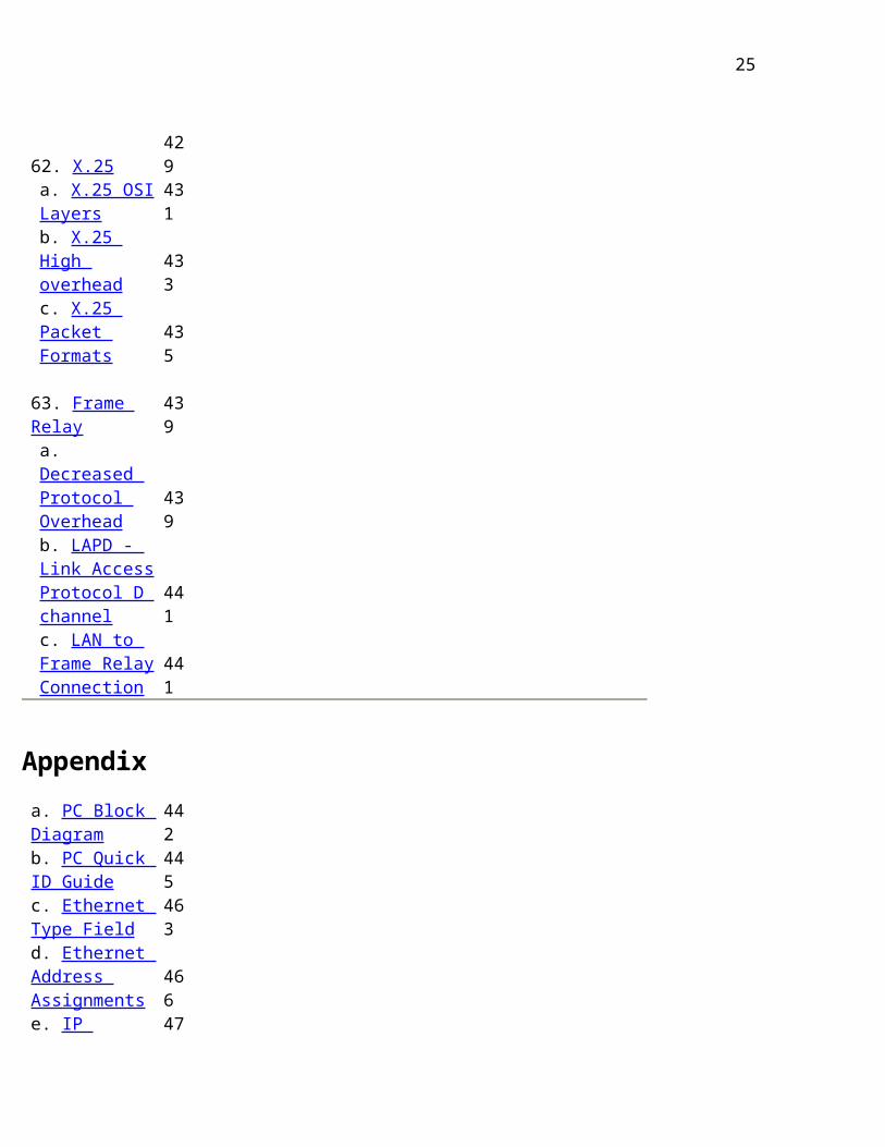
62. X.25 429
a. X.25 OSI Layers 431
b. X.25 High overhead 433
c. X.25 Packet Formats 435
63. Frame Relay 439
a. Decreased Protocol Overhead 439
b. LAPD - Link 441
15

Access Protocol D channel
c. LAN to Frame Relay Connection 441
Appendix
a. PC Block Diagram 442
b. PC Quick ID Guide 445
c. Ethernet Type Field 463
d. Ethernet Address Assignments 466
e. IP Protocol Address Space 470
f. IP Multicast Addresses 472
g. IP Header Protocols 476
h. IP Hardware Types 478
i. TCP/IP Well Known Ports 479
j. AT Command Set (Partial listing)493
k. ISO 3166 Country Codes 497
l. Token Ring - Major Vector IDs 499
m. The GNU General Public License 502
n. Copyleft Rules & Regulations 508
Introduction to Data Communications
Previous Top Next
16
Introduction to Data Communications
4. Data Communications
4. Data Communications
Data Communications is the transfer of data or information between a source and a receiver. The source transmits the data and the receiver receives it. The actual generation of the information is not part of Data Communications nor is the resulting action of the information at the receiver. Data Communication is interested in the transfer of data, the method of transfer and the preservation of the data during the transfer process.
In Local Area Networks, we are interested in "connectivity", connecting computers together to share resources. Even though the computers can have different disk operating systems, languages, cabling and locations, they still can communicate to one
17
another and share resources.
The purpose of Data Communications is to provide the rules and regulations that allow computers with different disk operating systems, languages, cabling and locations to share resources. The rules and regulations are called protocols and standards in Data Communications.
5. Why Telecommunications?
What does networking have to do with telephones? Telephones and networking work hand in hand. The telecommunications industry has been gradually integrating with the computer industry and the computer industry has been gradually integrating with the telecommunications industry. The common goal is to join distantly located Local Area Networks into Metropolitan and Wide Area Networks (MANs and WANs).
5a. Voice Channels
18

First thing that comes to mind is telephone systems and the phone at home. Talking to someone on the phone uses Voice Channels. This doesn't seem to have much to do with Networks!
We do use voice channels for modem communications to connect to BBSs (Bulletin Board Services) or to connect to the Internet. We also use voice channels to connect LANs using remote access. Due to the bandwidth limits on the Voice Channel, the data transfer rate is relatively slow.
Voice Channel: Dial-up connection through a modem using standard telephone lines. Typical Voice Channel communication rates are: 300, 1200, 2400, 9600, 14.4k, 19.2k, 28.8k, 33.6k and 56 kbps (bits per second).
5b. Data Channels
Data channels are dedicated lines for communicating digitized voice and data. At the end of 1996, there was a major milestone where more data was
19

communicated in North America's telecommunications system than voice.
Introduction to Data Communications Previous Table of Contents Next
20
Introduction to Data Communications
4. Data Communications
4. Data Communications
Data Communications is the transfer of data or information between a source and a receiver. The source transmits the data and the receiver receives it. The actual generation of the information is not part of Data Communications nor is the resulting action of the information at the receiver. Data Communication is interested in the transfer of data, the method of transfer and the preservation of the data during the transfer process.
In Local Area Networks, we are interested in "connectivity", connecting computers together to share resources. Even though the computers can have different disk operating systems, languages, cabling and locations, they still can communicate to one
21
another and share resources.
The purpose of Data Communications is to provide the rules and regulations that allow computers with different disk operating systems, languages, cabling and locations to share resources. The rules and regulations are called protocols and standards in Data Communications.
5. Why Telecommunications?
What does networking have to do with telephones? Telephones and networking work hand in hand. The telecommunications industry has been gradually integrating with the computer industry and the computer industry has been gradually integrating with the telecommunications industry. The common goal is to join distantly located Local Area Networks into Metropolitan and Wide Area Networks (MANs and WANs).
5a. Voice Channels
22
First thing that comes to mind is telephone systems and the phone at home. Talking to someone on the phone uses Voice Channels. This doesn't seem to have much to do with Networks!
We do use voice channels for modem communications to connect to BBSs (Bulletin Board Services) or to connect to the Internet. We also use voice channels to connect LANs using remote access. Due to the bandwidth limits on the Voice Channel, the data transfer rate is relatively slow.
Voice Channel: Dial-up connection through a modem using standard telephone lines. Typical Voice Channel communication rates are: 300, 1200, 2400, 9600, 14.4k, 19.2k, 28.8k, 33.6k and 56 kbps (bits per second).
5b. Data Channels
Data channels are dedicated lines for communicating digitized voice and data. At the end of 1996, there was a major milestone where more data was
23
communicated in North America's telecommunications system than voice.
Introduction to Data Communications Previous Table of Contents Next
24
Introduction to Data Communications
5. Why Telecommunications?
(cont'd)
5b. Data Channels (cont'd)
Data Channels are special communications channels provided by the "common carriers" such as Telus, Sprint, Bell Canada, AT&T, etc.. for transferring digital data. Data Channels are also called "Leased Lines". They are "directly" connected and you don't have to dial a connection number. The connections are up and running 24 hours per day. They appear as if there were a wire running directly between the source and destination. Typical transfer rates for data communication are: 56 k, 128k, 1.544 M, 2.08 M, 45M and 155 Mbps.
Common carriers charge for data connections by
1. the amount of data transferred (megabytes per
25

month) 2. the transfer rate
(bits per second)
3. the amount of use (time per month)
6. Introduction to Networking
What is a Network? This is a difficult question to answer. A network can consist of two computers connected together on a desk or it can consist of many Local Area Networks (LANs) connected together to form a Wide Area Network (WAN) across a continent.
The key is that 2 or more computers are connected together by a medium and they are sharing resources. The resources can be files, printers, harddrives or cpu number crunching power.
6a. The Big Picture
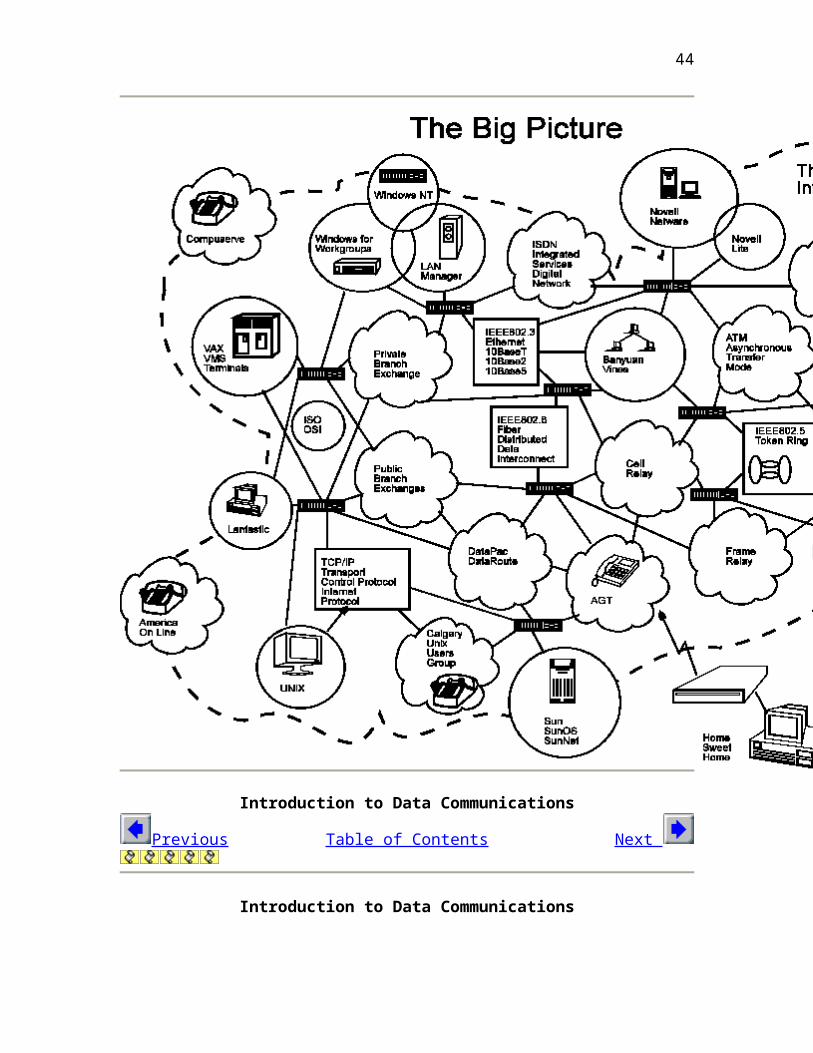
Many individuals have asked to see The Big Picture of networking: "where does everything fit in?". Where does Microsoft NT fit in with routers and the OSI
26
layers? What about UNIX, Linux and Novell? The following page has a graphic showing The Big Picture. It attempts to show all areas of networking and how they tie into each other. The following key describes the graphical symbols used:
Circles Network Operating Systems
Squares Communication & cabling protocols (OSI Transport to Physical Layer)
Storm Clouds Telecommunications media or Information providers that connect to the Internet
Machine symbol Network "linker" can be a Bridge, Router, Brouter or Gateway
The Internet jagged haphazard dotted line
Introduction to Data Communications
Previous Table of Contents Next Introduction to Data Communications
27
Previous Introduction to Networking (cont'd) Next
Introduction to Data Communications
Previous Table of Contents Next
Introduction to Data Communications
28

32. Introduction to the ISO - OSI Model
32. Introduction to the ISO - OSI Model
The ISO (International Standards Organization) has created a layered model called the OSI (Open Systems Interconnect) model to describe defined layers in a network operating system. The purpose of the layers is to provide clearly defined functions to improve internetwork connectivity between "computer" manufacturing companies. Each layer has a standard defined input and a standard defined output.
Understanding the function of each layer is instrumental in understanding data communication within networks whether Local, Metropolitan or Wide.
32a. OSI Model Explained
This is a top-down explanation of the OSI Model, starting with the user's PC and what happens to the user's file as it passes though the different OSI Model layers. The top-down approach was selected specifically (as opposed to starting at the Physical Layer and working up to the Application Layer) for ease of understanding of how the user's files are transformed through the layers into a bit stream for transmission on the network.
There are 7 Layers of the OSI model:
7. Application Layer (Top Layer) 6. Presentation Layer
5. Session Layer
4. Transport Layer
3. Network Layer
2. Data Link Layer
1. Physical Layer (Bottom Layer)
29
32b. Layer 7 - Application Layer
Fig. 1 Basic PC Logical Flowchart
A basic PC logical flowchart is shown in Fig. 1. The Keyboard & Application are shown as inputs to the CPU that would request access to the hard-drive. The Keyboard requests accesses to the hard-drive through user enquiries such as "DIR" commands and the Application through "File Openings" and "Saves". The CPU, through the Disk Operating System, sends/receives data from the local hard-drive ("C:" in this example).
Introduction to Data Communications
Previous Table of Contents Next Introduction to Data Communications
32b. Layer 7 - Application Layer
A PC setup as a network workstation has a software "Network Redirector" (actual name depends on the network - we will use a generic term) placed between the CPU and DOS as in Fig 2. The Network Redirector is a TSR (Terminate and Stay Resident) program which presents the network hard-drive as another local hard-drive ("G:" in this example) to the CPU. Any CPU requests are intercepted by the "Network Redirector". The Network Redirector checks to see if a local drive is requested or a network drive. If a local drive is requested, the request is passed on to DOS. If a network drive is requested, the request is passed on to the network operating system (NOS).
Electronic mail (E-Mail), client-server databases, games played over the network, print and file servers, remote logons and network management programs or any "network aware" application are
30
aware of the network redirector and can communicate directly with other "network applications" on the network. The "Network Aware Applications" and the "Network Redirector" make up Layer 7 - the Application layer of the OSI Model as shown in Fig 3.
Fig. 2 Simple Network Redirection
Fig. 3 PC Workstation with Network Aware Software
31
Introduction to Data Communications
Previous Table of Contents Next
Chapter One
Data Communications Basics
This chapter provides an overview of data communications, an area that is
receiving much attention for the past ten years. It aims at familiarizing the reader with terminologies, limitations and capabilities of current data communications systems. A successful computer system may be viewed as an integration of data-processing system and data-communication system. The function of data communication is to extend the processing power to cover wider area and overcome spatial limitation. Upon completion of this chapter, you should be able to:
Define telecommunications
Define data communications
Understand the data communication’s requirements
List the characteristics of cluster and distributed networks
List different network topologies
Understand the evolution of communications network
A distributed system is an integration of data processing, data communication system, a 3-D model.
Data communications and networking concepts
Communications
32

The contents of this Lecture Notes is about Data
communications, it is quite natural to define a few frequently used terminologies throughout this book. Communications by definition refers to the transfer of information from one place to another between two individuals using agreed symbols, signs or even human behaviour such as nodding. Below are a few examples involving communication.
Talking to your friend over a phone between Kowloon Tong and Shatin. In this example, at least a single telephone exchange with two telephone sets are required. The voice signal will be converted and amplified prior to reaching the called party. In addition, both sides can send/receive voice signals (Formal definition is full-duplex.) Writing a mail to overseas relative. In this example, there is no 100% guarantee that the mail will be correctly received by your relative. The delivery of letter is done by a third party and acknowledge on the receipt of letter is usually not provided to ordinary mail. (Formal definition is simplex.) Lecturing a course. In this example, the exchange of information is face-to-face and again is usually a simplex style, unless the student raises question. Voice, Drawing and Image will be used to deliver a lecture to the student.
Types of information during communication may include one or a combination of following:
Voice through radio or telephone. It was analogue signal and is being replaced by digital signal. Use of digital signals for communication has a lot of advantages: The signal could be reproduced with less distortion. In terms of reception quality, you will find that the voice part of NICAM system is better than the video part seen on the screen during adverse weather. It is because the audio part of TV signal is digitized while the audio part is still analogue and may be affected by the mis-alignment of antenna’s reception. Video picture seen on TV screen. The information to be carried is continuous images. Digital Data between modem and PC communication port 1 (COM1). In this example, the data transfer is called asynchronous mode (Not synchronous in the way of sending data.)
33

Image received by FAX machine
The signal types to be used in communication are summarized into:
Voice or audio, human speech Data, banking record Video Image, desktop scanned bit map Drawing, output of AutoCAD or AutoSketch
Multi-media Data
Multi-media technology is being developed to cover the above signal types into a single entity. A signle entity means within the network, there is no distinction on the types of signal. All of them are classifed as digital signals with different characteristics. For instance, delay on voice is more sensitive than text data during transmssion. A few more examples regarding the products are given below:
Movice = Video + Audio
Digital games = Music + video + software
Electronic books = text + data + graphics + music + photographs + video
Looking at the above classification, it is felt that video dominates the future data communications. Because of the limited bandwidth (data that can be transmitted per unit time), the video signal is needed to be digitised, compressed and stored in mutimedia storage warehouse called server . It is linked by transport networks to allow users to access.
Can you draw a distinction between drawing and image in terms of file size and supporting software packages if required to produce the picture?
The file size of “Drawing” is less than an image as it uses vector approach. The graphics also use simple geometric setting such as a circle can be represented by the centre and the radius, not the whole circle picture. This, of course, relies on the package to reproduce it.
34

Communication System
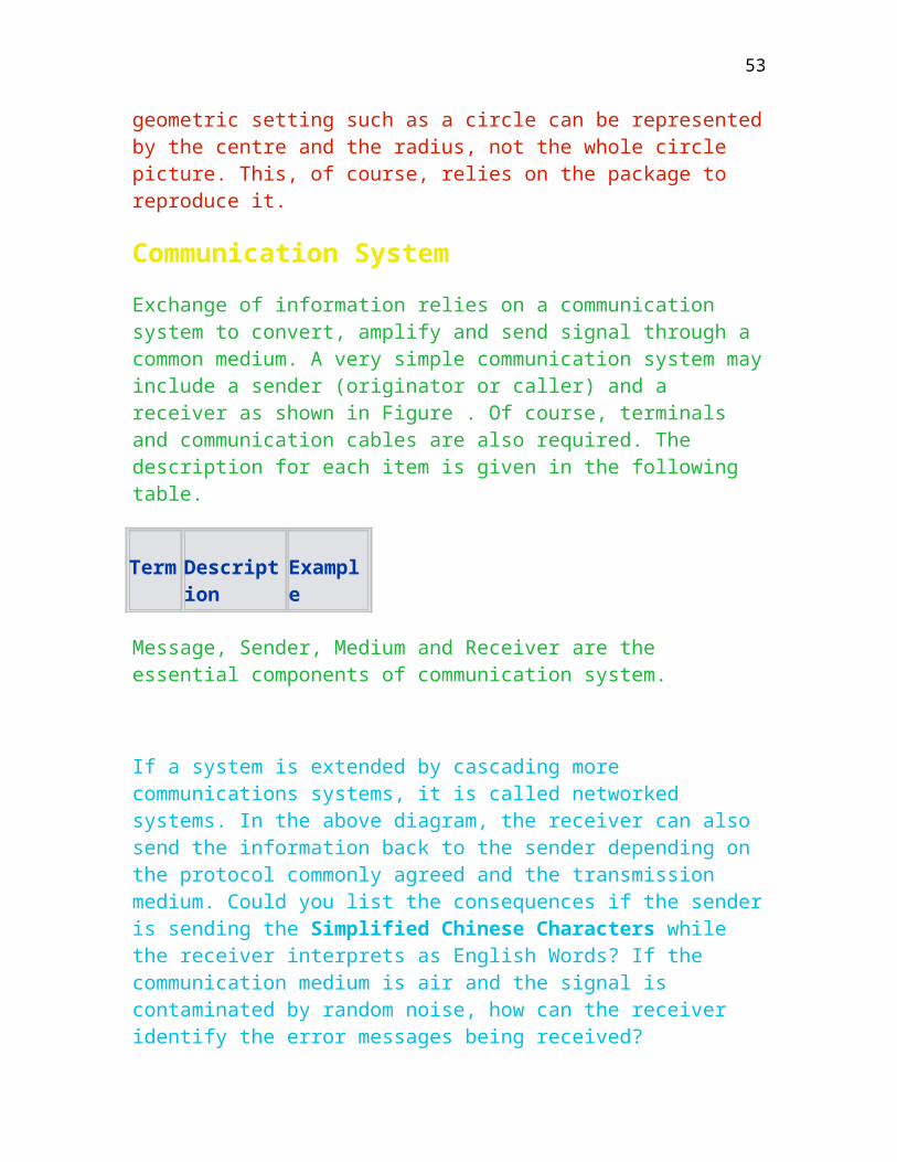
Exchange of information relies on a communication system to convert, amplify and send signal through a common medium. A very simple communication system may include a sender (originator or caller) and a receiver as shown in Figure . Of course, terminals and communication cables are also required. The description for each item is given in the following table.
Term Description Example
Message, Sender, Medium and Receiver are the essential components of communication system.
If a system is extended by cascading more communications systems, it is called networked systems. In the above diagram, the receiver can also send the information back to the sender depending on the protocol commonly agreed and the transmission medium. Could you list the consequences if the sender is sending the Simplified Chinese Characters while the receiver interprets as English Words? If the communication medium is air and the signal is contaminated by random noise, how can the receiver identify the error messages being received?
Telecommunications
In case, communication involves the sending of information over a significant distance, it must use telecommunications as an aid. By definition, Telecommunications refers to the transmission of information between distant locations by some electromagnetic means. A typical example is the microwave link currently being used by Hong Kong Electric between Lamma power station and major zone substations on Hong Kong island. The distance in between is over several kilometers and the links use extensive electronic based microwave equipment. Star TV involves Telecommunication by broadcasting the TV pictures through the satellite called AsiaSAT.
Assume that you are using a dial link to access the CityU’s Citylink, can you list which part involves the use of telecommunications?
35

A pair of modems used to convert the digital signal from the PC to analogue signal involves Telecommunications by sending/receiving the data through telephone network. The telephone network abbreviated as PSTN (Public Switching Telephone Network) is currently monopolized by Hong Kong Telecom. It is basically a voice network but can be used with the consent of Hong Kong Telecom to support data through a pair of modems.
How far does it take for an analog signal travelling over a voice network?
The speed in the telephone network depends on the speed of electronic. It is roughly half the speed of light that is 1.5x10⁸ km per second. Based on this Figure, can you Figure out it long it takes by a telephone signal from Hong Kong to Tokyo?
Data Communications
Data communications is defined as the interchange and processing encoded information between distant locations using Telecommunications. Encoded information refers to digital information and is nothing just a series of ones and zeros from one point to another.
Data communications is regarded as the collection and distribution of the electronic representation of information which can be text, voice, graphics or image, from and to remote computing facilities. As information can only be carried to the remote site provided that the information carrier supports that particular type of data transmission, information may undergo data conversion processes if the nature of data signal is incompatible with the characteristics of the signal carrier.
To illustrate the relationship between Data communications and Telecommunications, we group these two terms together with the aid of computers. You will find that data communication bases on the computer to process the digital information and relies on telecommunication equipment to deliver the information to remote receiver as shown in Figure Data communication is now even used by computer people as a single word datacommunication similar to telecommunication.
36

Teleprocessing is the combination of telecommunications and data processing. However, it is often used interchangeably with the term data communications.
Why Data Communications?
There are a few reasons behind, below are the most important three reasons.
It is beneficial if computers can exchange their data through the common links among them. This not only reduces document flow, but also saves time. Some companies in Hong Kong use Electronic Data Interchange (EDI) to do business (such as placing order, sending invoice, etc. through the network).
By use of data communications, tasks of distributed nature can be processed by distributed computer systems by exchanging data and/or intermediate results among themselves. For example, well known retail shops like Circle K can use Point Of Sale system to keep check the inventory level locally, sales summaries and request can be transmitted to the computer in headquarters for overall turnover.
It provides a way to link hardware, software, and data bases among computer systems in different geographical locations and what is more important is that this enhances a company to make better use of its computing resources. For example regional office may send a job, which is too big for its regional computer system to handle, to the headquarters’ computer system for processing and sending the result back.
The data communication is getting booming for the past 10 years due to the powerful capability of computer systems. Below are the trends for minicomputer.
Increased computation power. To measure the computation power, Million Instructions Per Second abbreviated as MIPS is used for the same CPU bus size. A 80486 PC is roughly 5 to 6 MIPS. Cheaper mass storage. Nowadays, to use a single 1M bit memory chip in PC
37

is quite common. 25 years ago, a popular ICL mainframe model only had 64K bytes as the main memory. Talking about the disk technology, it shows that the capacity will also increase exponentially with gigabyte capacity available in the near future. Multiple head/multiple platter magnetic technology and compact disk optical technology are both capable of providing cost-effective mass storage with this capacity. Increased data management capabilities. A lot of network management tools to monitor the performance of network and data management tool like Powerhouse are very common to keep check the performance of data and network. Reduction in cost. You probably find that the price of PC is roughly depreciated by half for about two years. A PC 80486 with 200M harddisk and Super VGA monitor is 8000+ in early 1994, which was 15000+ in early 1992 at Golden Arcade. Now a Pentium Pro costs less than HKD10000. A computer specialist therefore recommended the buyer not to buy the top model on sale in the market, as the buyer will get a similar type two years later at half the price. Increased in performance/cost. It is one of the factors to measure the computer’s performance in terms of MIPS/cost. Using this factor, IBM mainframe is extremely expensive than a 80486 PC or Prime Computer.
Can you draw the distinction amongst data, information and knowledge?
Data refers to pre-processed material and information refers to the processed data.
The use of telecommunication is to extend the computation capability offered by computer. More than 90% of computers are used in business to process the data and produce report, without telecommunication, the service only focus in the office environment. Use of data communication, on the other hand, allows different computers to group together to process the inter-related messages.
Up to here, can you clearly define the terms: communications, telecommunications and data communications?
Communications:
Telecommunications:
38
DataCommunications:
Computer Network
Network by definition refers to a group of interconnected devices communicating with each other. The device could be telephone exchange. If the device is a computer, it is called computer network. So, computer network is defined as a collection of computer systems that are connected together for the purpose of exchanging and sharing resources.
To call it a computer network involves three major components as listed below:
Computers. These are definitely required to process and relay messages between two remote parties. It is further classified into clustered and distributed. Clustered (There is only one machine or all the machines are grouped together) Distributed (This is the current trend for computer communications.)
To classify whether the system is partially or fully distributed, there are three factors :Is the data distributed amongst the nodes? Is the hardware distributed? Is the operating system used distributed? If the system can satisfy all of them, it is regarded as a fully distributed system.
Remote terminals attaching to the network. The terminal can also classified into two types namely: Interactive type such as VT100, IBM 3278.
VT means virtual terminal. It relies on software to conFigure the PC to behave like different terminal types such as VT200 or VT100. When you log into the VAX/VMS, you could use show terminal to find out the terminal type that you are using.
Batch like RJE (Remote Job Entry) by IBM series.
39
Communication links.
The link can be physical link such as telephone wire, satellite channel and telephone wire or logical link formed by software.
A physical wire can be shared by a few users simultaneously, the piece of time that is shared by user is regarded as software link and the physical wire itself is physical link. By use of communication software, a few physical wires could be grouped together to serve two machines is called logical trunk. An X.25 physical path can support up to 4096 logical channels.
Networking Concepts
Advantages of computer Networks
There are a lot of advantages by use of networked computers such as:
Resource sharing including program, data base, hardware etc.
You can now remotely search library catalogue belonging to The University of Hong Kong through UPGC network at City University of Hong Kong.
Graceful degradation of system upon component failure. One of computer node’s failure will affect part of the network only.
Cluster Network
A cluster network is a simple communication system with a single host processor or a few grouped processors at the same location. Terminals are connected to the host through telephone wiring. Data and executable files are also centrally located in the processors and are usually shared among users. The library system at City University of Hong Kong is a typical example. Figure is
40

a block diagram showing the relationship between a computing machine and terminals.
Explain why computer loading is also shared among users a clustered network.
Distributed networks
The network is characterized by connecting multiple processors geographically distributed within the network as shown in Figure . BITNET, Because It is a Time NETtwork, is a typical example of distributed network and is established to provide information transfer to international academic institutions. BITNET presently links more than 2900 institutional computers over 450 higher educational institutions and research centres in most countries including Hong Kong, Australia, Japan, Europe, United States etc. HARNET, Hong Kong Academic Research Network, is now upgraded with T1 link at the speed of 1.54 M bits per second with Ring configuration instead of Star configuration.
Can you distinguish the difference between Ring and Star network in terms of network topology?
The advantages of using distributed network are:
Flexibility for future growth and expansion. To add a node to the system is to make a physical connection with appropriate software to the boundary node. Versatile and reliable in terms of system down time
The network’s reliability can be measured in terms of system down time. That is how many seconds/minutes within a month/year the network is out of service.
Cost effective in terms of system growth and maintenance
Figure 3 shows the interconnection of a few distributed machines through a wide area network. The computers are interconnected through a common network.
41

Network Topologies
Network topology refers to the way of grouping/linking the communication nodes to serve particular need. Figure is an older version of HARNET (Hong Kong Academic Research Network) showing the connections with node names amongst the higher educational institutions in Hong Kong. The centre node was HKU’s HKUJNT.
Can you classify this type of network topology? Ring or Star.
Communication Subnetwork
Arrangement of the computers and the interconnections between them as shown in Figure with appropriate DCE, DTE and network boundary. Each computer in a network is called a node. The connection is known as an arc, path or link. Factors that should be considered in defining the network topology include:
Reliability in terms of system downtime Performance in terms of time required to perform data retrieval/update across various nodes. The minimum response time for an IBM SNA network is 3 seconds. Longer than this value is deemed to be poor performance. Flexibility in terms of system expansion, failure etc.
Network Topology
Network topology is broadly classified into point-to-point or multi-point depending on the data transfer within the network.
Point-to-point
Message has to be transferred between two adjacent nodes linking up by various transmission media. A Point-to-Point depending on the topology as given in Figure is further divided into:
Star ( A central node is required to relay messages)
42
Every device in the network has a dedicated point-to-point link to the central computer but not to others. Therefore, if one device wants to communicate with another device other than the central computer, it must pass its message to the central computer for re-routing. The central computer acts as the network controller.
Loop ( A message has to pass through several nodes in the system prior to be received by the targeted node.) The data movement can be either direction.
Tree (A top node irrespective of topology is still required.)
Complete (Direct connection between two nodes are formed.) This topology is ideal for military application in which reliability is the prime factor to be considered.
Irregular or Mesh (Irregular shape). There is no specific path and solely depends on the system growth. This network is widely used in business applications.
List the reasons why Irregular network is preferable in business environments?
Broadcast
Message is sent to all nodes within the network by means of common bus.
Bus topology like broadcasting radio or Ethernet network. It is essentially a single multidrop line shared by many nodes as shown in Figure . A message to be transmitted is placed on the common path and is broadcast to all the nodes. Obviously, all messages should be included with sender’s and receiver’s addresses. Messages which are not addressed to nodes in the network are ignored by them.
43
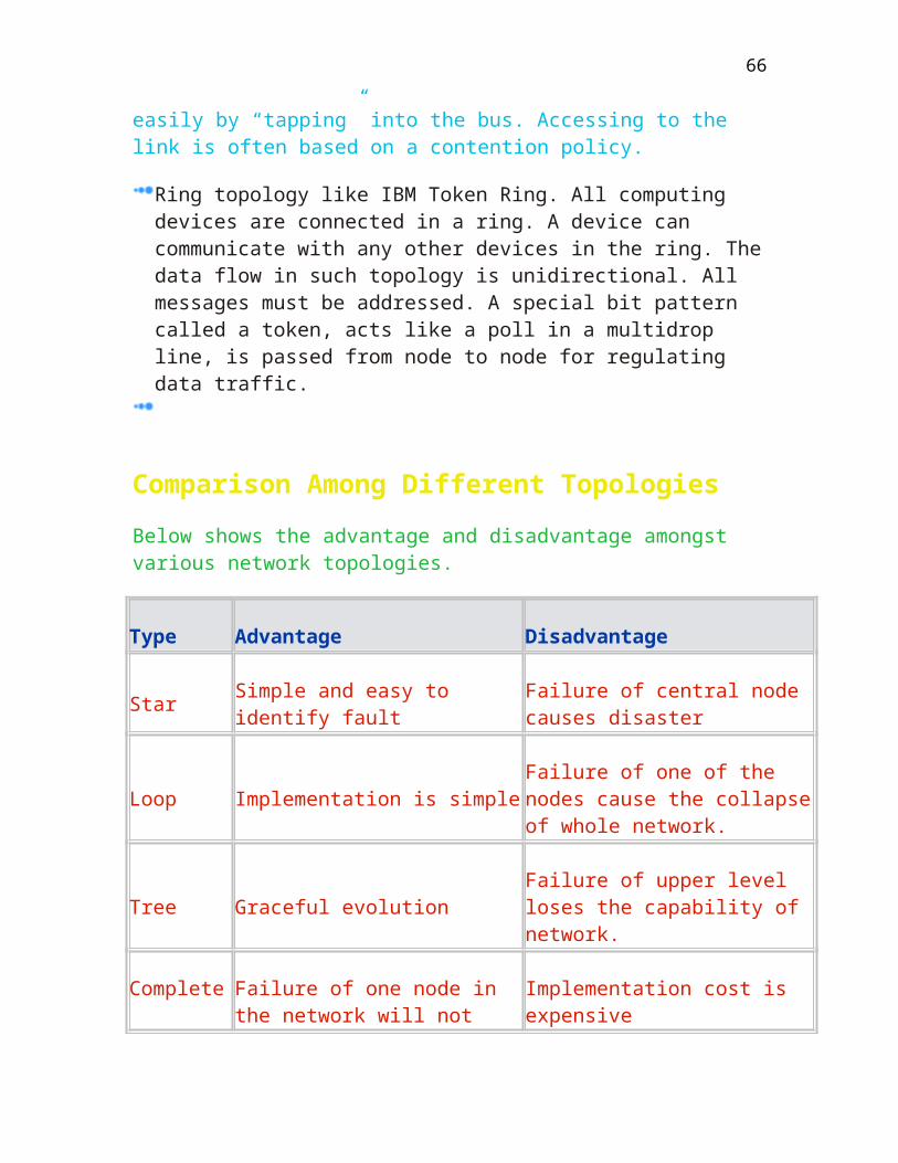
Failure of any nodes in the bus does not affect the other nodes. In addition, new nodes can be added easily by “tapping” into the bus. Accessing to the link is often based on a contention policy.
Ring topology like IBM Token Ring. All computing devices are connected in a ring. A device can communicate with any other devices in the ring. The data flow in such topology is unidirectional. All messages must be addressed. A special bit pattern called a token, acts like a poll in a multidrop line, is passed from node to node for regulating data traffic.
Comparison Among Different Topologies
Below shows the advantage and disadvantage amongst various network topologies.
Type Advantage Disadvantage
Star Simple and easy to identify fault Failure of central node causes disaster
Loop Implementation is simple Failure of one of the nodes cause the collapse of whole network.
Tree Graceful evolution Failure of upper level loses the capability of network.
Complete Failure of one node in the network will not affect the rest
Implementation cost is expensive
Irregular (Mesh)
Immunity to bottleneck and failure problems
Expensive to provide an alternative routing
Bus Simple to control traffic flow Only a single communications channel is required to service all the nodes
44
Ring Simple to implement One channel is required to service all
Network Applications
There are numerous applications using networked computers such as:-
A central host computer with networked stations. Access to remote program by use of IBM LU 6.2 in local machine. Electronic mail such as all-in-1 mail used in VAX Access to the remote database (Library cataloging system) Financial information (Hong Kong Stock Exchange provided by Reuters) E-commerce, Web-shopping and Electronic Data Interchange (EDI)
Basic Terminologies for Different Networks
Networks regardless of type and feature are classified into Vendor network or Commercial Network. Vendor network is usually the proprietary network manufactured by a particular manufacturer while the commercial network is formed by using a single vendor network or grouping a few vendor networks to serve a commercial need such as the JETCO is formed by connecting to a few local banks with communication protocols using TCP/IP, IBM LU 6.2, X.25, Bi-sync or even the Internet HTTP etc.
Commercial Networks
Abbreviation Description
ARPANET As created by the Defense Advanced Research Projects Agency whose project started in 1969.
The Internet It refers to the National Science Foundation Internet(NSFNet). It was part of APPARNET and was split into an Academic and Research base network running mostly the TCP/IP protocol. CityU is one of the Internet nodes and the Internet address is
45

144.214.2.3.
Telenet Is the commercial public service offshoot of ARPANET
CYBERNET Is the commercial time-sharing network of Control Data Corporation with Centers located around the world.
MARK III Is GE’s Information Service Network dealing with current exchange
TYMNET Is a subsidiary of Tymshare Inc., was originally developed as part of the time-sharing system.
SWIFT Is the Society for World Wide Interbank Financial Telecommunications. The asia service centre is located in Hong Kong.
DDX Is the Japanese packet switched network.
Datapak Is a packet switching network offered by Hong Kong Telephone company using a protocol based on X.25.
DATAPAC Is a Canadian packet switched network using a protocol based on X.25
Vendor Network
The network is manufactured and supported by the vendors.
Type Description
Communication Organisations
46

Communication standards are formulated and designed by certain International Organizations. A few well known organizations are:
Type Description
Network Evolution
The evolution of communication networks starts from primitive analogy telephone exchange to commonly used Local Area Network.
Telephone network
It was originally designed for the transmission of voice and is still the largest communications network in the world as shown in Figure . You can use this network to deliver voice, FAX or even low-resolution video image by use of video telephone, A pair of modems is used to convert the digital signal in analog form so that the signal will not be distorted after passing through the telephone network. A dedicated physical channel is required for each telephone conversation.
Terminal-based Distributed System
In order to extend the terminals, a pair of modems is used between the central computer and the teletype writer. The line speed is limited by the quality of public switched telephone network as shown in Figure . The current typical value is 28800 bps (Bit per Second) and is moving to the speed of 56k bps.
Large Terminal-based Distributed System
The communication loading is shared by the front process which will collect all the related messages after proper processing prior to sending to the host in order to reduce the host’s interruption as shown in Figure . A typical cluster controller is IBM 3174 which can support up to 32 IBM interactive terminals and is ideal for regional banking service in Hong Kong.
PSDN-based Distributed System
47

It is a digital network such as datapak developed by Hong Kong Telecom to allow multi-proprietary machines to connect to this network to exchange information. When you login to the CityU’s network, you already made a connection to Hong Kong Telecom’s digital network, X.25. The quality of message delivered is guaranteed by this network. Figure shows the PSDN based distributed system.
LAN-based Distributed System
As Local Area Network(LAN) is getting popular in small size office, there are a strong demand to connect various LANs and Wide Area Network such as X.25 together to provide distributed service. The network’s backbone as shown in Figure is commonly equipped with either coaxial or optical fiber. A network with the same protocol can be communicated with others through a repeater. The network also has certain gateways to talk to other non-LAN based system such as Asynchronous gateway to VAX. Nowadays, TCP/IP protocol is commonly used to link up multi-vendor networks to provide file transfer, E-mail, Internet-based product etc.
Explain why high speed backbone is used. If the network backbone is not a high speed medium, what is the consequence?
It can support multi-media such as voice and video. If it is not used, it becomes the bottleneck of the network.
The Internet
The term Internet is used in two contexts. The first one, an internet refes to the interconnection of two or more networks. The second one, the Internet, refers to the specific collection of interconnected networks spanning more than 60 countries throughout the world. The member networks are both WANs (Wide Area Networks) and LANs (Local Area Networks), which were initally academic institutions and research facilities. The internet now, apart form academia, consists of business organisations, government agenceis and even household Internet-like service subscriptions. Computers in the Internet fall into two basic categories: host nodes (servers) and terminals (browser). Host
48

nodes are used to attach a network to the internet. Non-host nodes, on the other hand, access the Internet through a host node but are not directly connected to the Internet. Access to the Internet is provided at three basic levels, namely, national, regional and local. National providers are commercial entities that sell access to the Internet. The Internet uses a variety of communications lines. The backbone nodes use T1 or T3 links to provide transmission from one area to another. Figure shows a fraction of Internet backbone Network in US. In Hong Kong, the internal central hub is located at Chinese University of Hong Kong with a high speed link connected to US Seattle.
What is http?
It is one of the services offered by the Intenrt and is called Hyper Text Transfer Protocol. This is the protocol used to transfer the Hyper Text in HTML format.
Self-examined Questions
List the definition of data communications.
List two reasons to explain why data communications is getting booming for the past ten years.
List THREE characteristics of cluster networks.
List THREE characteristics of distributed networks.
49

What are some of the reasons for having networks?
What is the difference between a loop and a ring network?
List two different network topologies.
List the THREE categories of data communication components.
Briefly list the components in a typical banking network in Hong Kong. (Hint Each branch is equipped with a cluster controller to serve a few banking terminals.)
When you are using the ICQ, what is the network topology? Point to Point or Broadcast.
50

Chapter Two
Basic Communications Theory
This chapter is about the communications theory, transmission modes,
modulation and data compression techniques related to communications system. It describes how data flow is represented in terms of bits per time unit, and figures out maximum data transfer rate between two end points referenced to channel bandwidth, signal to noise ratio and the conversion of digital signals into analogue format over a voice-graded network. Upon completion of this chapter, you should be able:
Understand the basic transmission theory, and figure out the maximum data rate.
Identify the three transmission modes: Simplex, Half-duplex and Full-duplex
Classify the differences between serial and parallel transmission in terms of cost, data rate and suitability
Describe various analogue and digital modulation techniques
Understand various data compression techniques
Introduction to Information Transmission Theory
Information representation
Information as discussed in chapter one can be transmitted in a transmission medium as a representation of passing information to the receiver. The transmission medium can be one of the following:
Telephone wire used by telephone set Air used by radio transmitter
51

Optical fiber used as a backbone for various low speed local area networks Coaxial cable for closed circuit television
The signal relies on the variation of physical property such as the voltage level and current value. These varying physical properties can mathematically be represented as a function of time. Using Fourier transformation, any reasonably behaved periodic function can be represented as a summation of Sines and Cosines.
where t stands for time, f = 1/T is the fundamental frequency shown in figure for the waveform being analyzed, an and bn are the sine and cosine amplitudes of the nth harmonic, g(t) is the original waveform, and C/2 is the average value of original signal.
The information such as digital data between your PC and modem is a periodic signal where the period depends on the modem speed. Can you figure out the transmission period for 2400 bps?
The advantages offered by using Fourier series include:
any complex real-time signal bandwidth, which is difficult to understand, can be identified and analyzed in frequency domain in terms of bandwidth, signal amplitude, frequency and phase. signal distortion against frequency spectrum could be shown in frequency domain. This provides a clear picture against the signal characteristic. signal amplification against frequency spectrum could also be analyzed.
Signal analysis
Any Sin or Cos waveforms as given in figure can be measured by three physical quantities namely Amplitude, Phase, and Frequency:
Quantity Description
Amplitude Absolute measure of the height of the wave in voltage or Peak-to-Peak value.
52
Wavelength It is a measure of a distance for a periodic cycle.
Phase Relative measure of the difference in time between waves. The unit is in either degree or radian.
Frequency Absolute measure of the number of times a wave repeats per unit time.
Can you list the peak-to-peak value in above picture?
2 volts, as it is measured between the peak and valley.
The velocity V of a wave travelling is determined by frequency and wavelength as given below:
V = f
is the wave length and f is the frequency.
The speed is close to light speed in the air and is roughly half the speed for electronics travelling in copper wire. The propagation delay for an electronic from Tsim Sha Tsui to Shum Chung is therefore around 266 x 10-9 second, assume the distance is 40 km and the speed is half the light speed.
Can you figure out the propagation delay between Hong Kong and Peking?
You need to find out the distance between these two locations and use the simple formula time = distance/velocity
Bandwidth
Any analogue signal is not formed by a single frequency if it is expanded in terms of Fourier series. In fact, the waveform such as voice produced by human being consists of waveforms of many different frequencies. The bandwidth as shown in figure is defined by the difference between the points:
53

Bandwidth = fh - fl
where fh is the highest frequency and fl is the lowest frequency. Bandwidth is characterized by:
The more bandwidth, the higher the quality of signal to be delivered across the medium. Signal outside the bandwidth will be distorted by the transmission medium. This explains why digital signals generated by computer output port cannot be directly sent out across a telephone network, as the network will chop off the signals over 3400 Hz, which is the upper frequency limit produced by human being.
Based on the conversion to frequency spectrum, any periodic time varying signal can be viewed as a series of frequency signals with limited bandwidth. The bandwidth for a copper signal is around 10KHz, 350MHz for coaxial cable, and 550MHz for single mode optical fiber. Also note that coaxial cable can carry video signal while telephone wire can support voice and low speed data.
Examples of harmonics
Signals are usually grouped into broadband or baseband depending on the signal characteristics. Baseband transmission refers to sending the digital data along the transmission channel by means of voltage fluctuation such as IEEE 802.3 and IEEE 802.4 and Broadband transmission refers to the sending of data by modulating with high-frequency carrier wave such as AM or FM radio. Note that to form a digital waveforms, more harmonic signals are required as shown in Figure . The square waveform will be distorted after passing through a low pass filter as shown in the same Figure.
Channel capacity
Channel capacity refers to the maximum data rate for a finite bandwidth transmission medium in the presence of random noise. It is concerned about the quality of a specific communications channel and was identified by Shannon. The relation is governed by:
Maximum data rate = W x log2(1 + S/N)
54

Where:
W is the bandwidth of transmission medium S/N is the signal to noise power ratio Maximum data rate is measured in bits/second
Practically, this limit is seldom reached. To increase the transmission rate, the designer should either increase the signal power or use alternative medium with higher bandwidth.
The bandwidth for a telephone network is usually restricted between 300Hz to 3400Hz by telephone exchange. As a result, signal that is out of this range cannot be transmitted over the PSTN. That is to say, if you inject a signal of 10K Hz over the speaker, the remote cannot hear it. Interesting!
Note that for a theoretical noiseless channel, the maximum data rate that a channel can carry is nW symbols/per second. A symbol can be n multiple digital levels instead of 0 or 1.
Decibel
As the signal to power ratio is usually quite significant, a better representation in communications is used to express the ratio of two values in logarithmic format. The values can be power, voltage or current. It is not an absolute unit, just a relative Figure and is expressed in:
dB = 10 log10 P1/P2
Where:
dB number of decibels P1 the first value of the power P2 the second value of the power
It is often used to measure the ratio of signal to noise in a communications channel due to large quantity of signal power. For example, if the signal power is 1K Watt and the noise power is 1m Watt, there is no point to have a ratio written in 1000,000.
55

What is the signal to ratio value in db if S/N is 10000?
10log(10000) = 40dB
A certain modem’s speed is 2400 bits per second and the equivalent symbols per second is 600. What is the symbol level?
4 levels, 2 bits are required to represent the signal.
For a certain equipment, if the S/N is 1000, the bandwidth is 10 KHz and the maximum speed is up to 9600 bits per second, how many percentage of bandwidth is not used? (Hint: You should find out the theoretical data rate first using the formula in section 1.5 .)
What is bandwidth? How is bandwidth measured in what unit?
3db difference and is measured in Hz, KHz, MHz or GHz.
Coding Data in Signals
As discussed above, the transmission rate is related to the bandwidth of transmission medium and signal to noise ratio. To increase the transmission rate, one can extend the signal to multiple level. This approach to increase the information transmission rate is suitable for computer to process the faster information as shown in Figure .
The information (data) rate for a two level coding signal with pulse width equal to 20 ms is calculated by log22/20 ms = 50 bits per second as shown in Figure .
The information (data) rate for a four level coding signal is log24/20ms = 100 bits per second, twice the former case. Note that the signalling rate (1/20ms) is the same for both cases.
Restriction on Coding level
56
It seems to be if you can extend the coding level, we can achieve higher speed. However, this is not the case as the coding level for an information is restricted by:
Physical properties of transmission medium (sky, telephone cable, coaxial cable) such as resistance, attenuation, capacitor of the medium etc. Intelligence of machine to identify the coding level. The larger coding level, the more intelligent the machine is. Noise level in terms of power presented in the medium to contaminate the resultant signal.
Noise is always presented in the transmission medium. There is no method to get rid of them. It is technically feasible to reduce the noise level. As a result, the coding signal cannot be extended to an unlimited level.
Any more reasons to explain why it cannot support more levels?
In section 2, if the signalling rate is changed to 40ms, what will be the new data rate?
For the same question, if the level is extended to 64, what will be the new data rate?
Data Transmission Modes
Channel type
Irrespective of direction of data transfer, there are THREE types of transmission channels being used to exchange information as shown in Figure .
Type Description
Simplex
One party in the communication can send data to the other, but cannot receive data from the other end such as the radio pager. It is usually not restricted by the transmission medium, but the nature of communication devices.
57

Half duplex
Both parties can send and receive information from the other end, but not at the same time such as walkie talkie. Each time the sender has to press the transmission button before transmitting data.
Full duplex
Both parties can send and receive information at the same time such as computer to computer communication or telephone to telephone. A full duplex can be logically regarded as two half duplex operating in reverse direction.
Serial / Parallel transmission
The digital information regardless of channel type channel can be classified, in terms of transmssion format, into serial or parallel transmission. Serial transmission means to transmit the data bit by bit, whereas parallel transmission means to transmit data byte by byte, word by word or even more.
Serial
The bits are transmitted one after another on the same channel such as terminal to computer communication. Figure is a series of data stream transmitting from the right handed side modem to the left.
It is interesting to note that the first bit to be transmitted is B1 which is the least significant bit , not the most significant one.
Parallel
The bits are transmitted all at once (byte by byte) such as computer to printer communication as shown in Figure .
Asynchronous / Synchronous Transmission
58

In serial transmission, the transmission format can be further classified into Asynchronous and Synchronous.
Asynchronous transmission format
It is guarded by start and stop bits and the character to character space is random as shown in Figure . The efficiency is limited to 70% taking the start bit, stop bit and parity bit into account.
Asynchronous character format
The initial and final states are idle which corresponds to -12 volts in terms of voltage level. An odd parity bit is appended to the data bits for the detection of transmission error as shown in Figure .
Asynchronous Electrical format
The voltage level spans between -12 and + 12 volts as measured between either the transmit (Pin 2 in RS-232-C) or receive (pin 3) with respect to signal return (for RS232 C is pin 7) as shown in Figure .
Synchronous Transmission format
The characters are packed together and there is no gap between two characters. Sync is a special character used to synchronize the data reception as shown in Figure . Usually for a bisynchronous format, there are four synchronous characters preceding the data. In case there is no character to be delivered by the transmitter, a special character such as 7E in hexadecimal is used to pad the data.
Start, Stop and Parity bits are not required in synchronous transmission. As a result, the transmission throughput is roughly twice the asynchronous transmission for the same operating speed.
Synchronous character format
Synchronous data is usually driven by a clock. The clock signals can be either external provided by the modem or internal provided by the computer port (Pin number 24 in RS232-D). The clocking signal provided by internal clock is
59
usually lower than external clock as extra CPU time is required to produce the clock by the computer as shown in Figure .
If the clock is generated by modem, it is called external clock. The modem speed can be dynamically changed by the user even a file is transferring. This is one of the acceptance tests to verify whether the communication software is robust or not.
Asynchronous / Synchronous Characteristics
The characteristics of asynchronous transmission (communication between your PC and modem) are:
Random transmission of data units. That is there is no relation between any two characters and a transmission gap may exist between two characters. No synchronization between sender and receiver. It is triggered by the start bit and is terminated by the stop. Once a start bit is received by the receiver, it will sample the succeeding data bit to determine the binary value. The sampling rate is the line speed and is programmed by the user. The transmission speed is lower than synchronous transmission and is ideal for low volume data. The data format is framed type, as it is guarded by start and stop bits.
The characteristics of synchronous transmission are:
Data is transmitted in block. Usually, each data block is called a frame. The data block is needed to be synchronized between the sender and the receiver such as the insertion of sync characters for BI-SYNC or del (7E) if no data is transmitting. Synchronous transmission format is ideal for high speed and high volume data.
Synchronous transmission can be further grouped into two:
Character oriented such as RJE (The computer will process the received character to determine the meaning of data. This format was developed a long time ago by IBM and is still widely supported by various computer manufacturers)
60

Bit oriented such as X.25 and IBM SDLC (The meaning for the data format is fixed. The first character is a flag followed by the physical address of device connected to the network. In terms transmission performance, this approach is far better than the former one.)
Asynchronous Handshakes
There are two major handshaking methods being used by the computers for asynchronous data format. The objective of using handshaking is to protect slow device from being overrun by fast device.
Software - By sending appropriate characters to resume or suspend the data flow between two parties ENQ/ACK DC1/DC3 or (Xon/Xoff) DC1/DC2/DC1 (in Block mode) Hardware - By setting or resetting the control signals to resume/suspend the sending of data from the computer RTS/CTS DTR/DSR (widely used by serial printer)
ENQ/ACK
This method was developed by HP to protect the terminal from the CPU as shown in Figure .
The sequences are:
send a Data block to the terminal ( 1 record in size)
send an ENQ to the terminal to check whether the terminal is ready (are you ready?)
send an ACK back to CPU indicating that (I am ready)
send another data record ( repeat the procedure)
61

DC1/DC3 (Xon/Xoff)
It is quite common in industry to provide handshaking between two communication devices.
DC3 (XOFF, CTRL-S from the keyboard) is used to stop transmission DC1 (XON, CTRL-Q from the keyboard) is used to re-start the transmission
The sequences are shown in Figure .
DC1/DC2/DC1
It was invented by HP as well to protect the CPU from overloading data from terminal as shown in Figure .
The sequences are:
Sequence Status of Sending Control characters
Description
1 DC1 I am here
2 DC2 Press “Enter” key to continue
3 DC1 Okay to send the data
4 Data Actual data block from terminal
DC1 in Hex is 11, DC2 is 12, DC3 is 13, DC4 is 14, ENQ is 05 and ACK is 06
List the major difference between section 4.1 and 4.3. (Hints: Data to terminal or data to computer.)
62
Modulation
Modulation is used to translate digital signals to analog signals which can be transmitted over a transmissions medium without distorting the signals. The original digitals sent by a computer is usually not appropriate for transmission in a voice-grade channel. A pair of modems is used to generate a carrier in which the digital data are modulated on to this carrier. Below diagrams are used to demonstrate the resulting signal after modulated by a high frequency signal. The envelope is the modulating signal as shown in Figure . The transmission carrier used to modulate the original signal will be altered corresponding to digital pattern.
Type of modulation
Modulation can be grouped into two categories:
Analogue modulation as shown in Figure , the enveople of the carrier signal is the original signal to be transmitted. Digital modulation — to convert the analogue signal into digital format (CODEC) such that the data can be carried over a data network. A typical example is to sample the voice and code it using Pulse Coded Modulation.
Analogue
There are THREE basic modulation techniques using the physical property of sin wave as given below:
Amplitude Modulation (ASK) — using the amplitude of carrier wave to represent binary data. For instance, 1 v is used to represent binary 1 whereas -1 v is used to represent binary 0. Frequency Modulation (FSK) — using the frequency of carrier wave to represent binary data. For instance, 1K Hz is used to represent binary 1 whereas 2K Hz is used to represent binary 0. Phase Modulation (PSK) — using the phase of carrier wave to represent binary data. For instance, 90 out of phase is used to repesent binary 1 whereas 180 out of phase is used to represnt binary 0.
63

Phase and Amplitude modulation can be combined to provide better quality or to support higher transmission rate.
Explain why there is no wavelength modulation.
It is difficult to measure the wavelength. As a result, it is difficult to assign binary data to the variation of wavelength.
Amplitude Modulation
Also known as Amplitude Shift Keying Was originated with the telegram for low speed operation and is not used very much nowadays. Large carrier amplitude is a mark (-voltage level) or binary 1 Small carrier amplitude is a space (+voltage level) or binary 0 Frequency is constant for the carrier signal
The receiving modem can tell the difference between large and small amplitudes and can regenerate the signal corresponding to 1 or 0 as shown in Figure .
Frequency Modulation
The characteristics are:
It is also called Frequency Shift Keying as the change of frequency represents different binary data. One frequency represents mark One frequency represents space Amplitude is constant Continuous carrier transmitted Used for low and medium speed modems
The receiving modem has a discriminator which allows it to recognize the frequencies corresponding to the marks and spaces as shown in Figure .
64
If the channel bandwidth is only 3.2 KHZ, what is the requirement for the frequencies used?
Phase Modulation
Note the change in phase with respect to an original signal waveform as shown in Figure .
This method is also called Phase Shift Keying Imposes phase shifts on carrier - that is the phase of the signal is used to carry data instead of frequency or amplitude. Hence the amplitude is constant and frequency is constant. Commonly used in medium and high speed modems
More information can be transmitted using different phase shift. For example, the V26 2400 bps modem can handle bits in pairs using four combination of phase running at 1200 HZ. Details are given below:
Dibit Relative phase
00 +45o
01 +135o
11 -45o
10 -135o
To provide more information, different modulation techniques can be combined together such as Quadrature Amplitude Modulation as shown in Figure which is a combination of phase and amplitude modulation. Here, to send out a data stream of binary 11, phase -45 is used, wherase, the phase 45 is used to represent binary 00. You can compare this with amplitude modulation in which
65
an amplitude represents a binary data. If we combine the phase and amplitude together, we can generate more binary data.
Example of Phase Modulation
Figure shows phasor diagram with two examples and eight phases (0, 45, 90, 135, 180, 225, 270, 335). It provides 16 different signals, each of which can represent 4 bits. This combination provides a quadbit capability known as quadrature amplitude modulation (QAM). If it is used on a 9600 baud line, it can provide transmission of 38400 bps (4x9600).
Modulation Techniques Used on Typical Modems
The following CCITT (ITU-T) standards describe the type of modulations and their maximum speed. It is found that by combining the phase and amplitude can offer higher transmssion rate. The standard refers to the communication method between modems not between modem and PC. The connection between modem and PC is RS232D using minimum three pins only. The three pins are transmit (pin 2), receive (pin 3) and signal return (pin 7 and is common to transmit and receive). As you are aware that the standards given below are quite old, as the spped is less than 56K bps. However, it gives you an idea the development of standards and its relationship with the line spped.
Type CCITT or ITU-T Nature Bits/s
Frequency Shift Keying V23 4WFDX 1200
V23 2WFDX 1200/75
V21 2WFDX less than or equal to 300
Phase Shift Keying V22 2WFDX 1200
V26 4WFDX 2400
66

V27 4WFDX 4800
Quadrature Amplitude Modulation
V22 bis 2WFDX 2400
V29 4WFDX
9600
FDX or HDX : refers to Full Duplex or Half Duplex in physical layer
4W or 2W : refers to the use of 2 wire or 4 wire connection between a pair of modems
Bits/Sec and Bauds
These two terms are usually misused significantly.
Type Description
Bits/Sec Refers to the actual information transfer rate that can be achieved on a given channel. It is the result of different coding level and signalling rate.
Baud Rate Refers to the fundamental signalling rate used on the circuit.
For example, the V22 modem as listed above, the carrier frequency is 600 Hertz. The fundamental signalling rate again is 600 baud and an information transfer rate is 1200 bits/sec. Note that it carries 2 bits for each operating cycle.
Draw a diagram and explain why bits/sec and baud are quite different?
67

Baud rate refers to the symbol per unit time of which a symbol might consist of two levels (one bit), four levels (two bits) or even more. Bit/s refers to the actual measurement of data transmission.
Digital Transmission
With the introduction of digital lines, direct transmission of digital signals becomes possible without converting to an appropriate analog signal. The advantages offered by digital network include:
Lower error rate (error rate is 1/109 ) for optical fibre Higher transmission speed (up to 625 Mb/s or even up to 1000 M b/s) Efficient use of channel by using digital multiplexing techniques, which means that it can support more users.
For analog signals such as voice in Figure , they have to be converted into digital form before they can be passed through. Similar to Modulation and Demodulation, Codec (Coding and Decoding) is designed to digitize (sample) and regenerate the analog signals. The common modulation methods can be grouped into:
Pulse Amplitude Modulation Pulse Duration Modulation Pulse Code modulation
It is based on the principle found by Nyquist in which a bandlimited analog signal of bandwidth W can be sampled and recovered at the other end without any distortion provided that the sampling frequency is more than twice the signal bandwidth (2W). Voice and video are typical examples of bandlimited signals. Usually, the bandwidth for human voice is below 10 KHz and most of people speaks between 300Hz and 3200 Hz. If a transmission medium , say 100 KHz is used, it can theoretically support up to 100 K/3K = 33 users provided that each signal is appropriate to be modulated to different channels. Figure is the diagram showing the resultant sampling signals for two channels.
If the bandwidth for channel 1 and 2 is 3.2KHZ, what will be the minimum sampling rate without producing contaminated signal?
68

If the sampling rate is less than the calculated value, what is the resultant output?
Can you fill in the following table?
Input Signal Network type Modulation Required (Y/N)
Analog Analog (old telephone switch)
Digital Digital (Internet)
Analog Digital network such as X.25
Digital Analog network such as radio network
Pulse Amplitude Modulation
Different height of pulse trains is used to represent the different signal voltage level as shown in Figure . The original signal is modulated by a constant pulse train to produce the modulated signal. Note that the envelope represents the original signal.
Pulse Duration Modulation
Different duration (length of each pulse) of pulse trains is used to represent the analog signal as shown in Figure . Again the original signal is modulated by a constant pulse trains.
Explain why the above-mentioned two cases are not appropriate for computer processing.
69

Computer has to detect either the height or width and is not accurate.
Pulse Code Modulation
The Pulse Amplitude Modulation is still regarded as analog signal because of varying nature of signal. This signal can be represented by a combination of codes known as Pulse Code Modulation which is more appropriate for digital transmission over long distance. This modulation method is commonly used nowadays.
NICAM samples the voice signal using 213 levels and compress the 13 bits into 8 bit output.
To code the PAM signal, there are two steps namely quantization and encoding involved.
Type Description
Note that a quantizing error is introduced during the quantization process because of truncation of analog signal. To reduce the quantization signal, smaller quantizing step is required. Because of nature of analog voice signals, small amplitude signals dominate. It therefore introduces more quantization error for weak signals if linear quantization method is used. To improve the quality, non-linear quantization steps with more steps in low amplitude signals are required as shown in Figure .
Self-examined Questions
Short Questions
What is the maximum data rate for a voice-grade line with a bandwidth of 3200-HZ and a S/N ratio of 10000 to 1?
70

For the above question, what is the maximum data rate if the S/N ratio is 40 dB?
List an advantage and disadvantage for parallel and serial transmission.
Briefly explain why a pair of modems is required to transmit the digital signals over a long telephone wire.
What is the purpose of the carrier wave?
When is bits/sec different from baud rate and when they are the same?
How many frequencies are required for a 2-wire full duplex operation using frequency modulation?
For the same question, how about the case for 4-wire full duplex?
71

True or False
ENQ/ACK is commonly known as XON/XOFF
A stop bit is a space
A space is a logical one
Synchronous transmission is known as start/stop transmission
ASCII has no provision for parity bit
Modulation is not required for digital signal over digital network.
Xon is equivalent to CTRL-S entered from the keyboard.
72
Chapter Four
Transmission Media and Network Devices
This chapter covers various transmission media available in Hong Kong for
transferring information, the characteristics and the ways to carry data during its transmission are also included. Network configurations between two ends including point-to-point and multi-point are also covered. The final section of this chapter is about the supporting communications devices in a network to facilitate the transportation of data. Upon completion of this chapter, you should
Understand different transmission media including telephone wire, coaxial cable, optical fiber and microwave link
List the different network configuration methods
List the different communication devices such as PABX, patch panel, switch, front-end processor etc.
Transmission Media
Transmission media used to provide a connection between sender and receiver to exchange information are generally grouped into two major categories namely guided and unguided.
Type Description
Guided
Signals are transmitted via a physical and tangible guide between the communicating points. These include twisted pair telephone cable, optical fiber, waveguide, and coaxial cable.
73

Unguided Physically, there is no direct physical connection between two points such as microwave and satellite links. Your mobile phone also uses unguided transmission medium.
Can you classify Light Frequency Infrared?
Unguided
Guided transmission media
Wire pairs or telephone wire
Wire pairs are the most common medium in short distance such as connecting computer port to modem or telephone set to telephone exchange. The modular telephone jack installed in your house makes use of telephone wires. The wires are made of copper and coated with insulating material like PVC. The cable is highly reliable if it is protected by telephone duct. The transmitted signal relies on the movement of electronics. It is manufactured in twisted wire pairs in order to reduce crosstalk. You usually experience this effect while talking to your friends over the phone and hear a very low background voice. The bandwidth of an ordinary telephone wire is limited to 10KHz and is further limited to 3300 Hz if it is used in Public Switching Telephone Network(PSTN). Higher bandwidth will be chopped by the Switch. That is to say, even the telhone line can support up to 10 Mbps, the CODER (switch coder and decoder) will convert the analogue signal into 8K (sampling rate) x 8 bits (256 levels) = 64 Kbps signal internally.
It is the cheapest transmission medium and costs around 2 dollars per meter depending on the quality, shielding and number of wires. The typical number of wires in the cable is two (Twist) or four(Quad). To support wider area, Using the Shannon’s theory, the maximum transmission speed per link can be over 10Mbits per second, which of course depends on the medium bandwidth and the distance between two end points. Figure shows a few examples of wire pairs.
Local Area Network (LAN) can support transmission rates over 16 Mbps or even 100 Mbps over twisted telephone wires. This type of telephone cable is
74

Category 5 cable, which supports this speed at a short distance. If you subscribe Interactive TV (ITV), they will replace your telephone cable by quad Category 5 cable to support voice and video.
Can you figure out the unused bandwidth compared with a modem operating at the speed of 56k bps?
Coaxial cable
It is basically a single wire surrounded by a tube-shaped conductor of solid copper. The signal is transmitted by use of of microwave rather than electronics. Because of high bandwidth (up to 350 MHZ with theoretical data rate up to 4~500 Mbps), it can support very high speed for data travelling. Coaxial cable is used for long distance communication such as Ethernet (CSMA/CD) and TV system between the antenna and TV set. Coaxial cable can be grouped into two types: broadband and baseband. In baseband transmission, digital signal like Manchester Code will be used to carry data along the channel, which relies on voltage fluctuations. In Broadband transmission, the digital data is modulated into different frequency channels separated by frequency guardbands. Because of wider bandwidth and more frequency channels, broadband transmission can support a mixture of signals such as voice and video. The cost of coaxial cable is more expensive than telephone wire and costs around a few Hong Kong dollars per meter. Figure shows the male and female coaxial cables. Baseband coaxial cable also allows the DC voltage to pass, which is necessary for collision detection in Ethernet network.
Four-wire telephone cable is regarded as quad with individually insulated and housed in a jacket. In Local Area Network, coaxial cable is called Thick Wire and Telephone Wire is Thin Wire. If the coaxial cable is damaged, the signal will attenuate sharply. This prevents the third party to tap information.
Optical Fiber
It is a popular high bandwidth transmission medium and is used in backbone communication as shown in Figure . Signal is transmitted by use of light through the glass fiber. It provides an electrical isolation and totally reduces electromagnetic interference or noise by surrounding equipment. Unlike telephone wire, installing and connecting the fibers requires special equipment. The transmission rate can exceed 2 G bps, nowdays around 6 ~8G bps and is
75

the highest transmission medium in the world. Recently, Hong Kong Telecom is laying fiber optic cables to provide data superhighway to support personal video services. It is expected that the future communications network in Hong Kong will consist of one optical fiber with coaxial cable as the backbone within the building. The terminator erected around each three stories will provide a transmission bandwidth to each household at 20 M bps. At that you can use it to watch movie, shopping, a real e-commerce world.
Figure shows a typical circuit that converts the digital signal to light travelling along the optical fiber. Here, the electronic signals are converted into light signals passing along the optical fibre and received by the remote. The remote then converts the light signals into electronic signals. Note that light emitting diode and photo diode are used to convert the electronics signal and accept the light signal.
Unguided transmission media
Microwave relays
It consists of transmission tower responsible for transmitting or repeating the signal for each hop (the distance is around 30 Kilometers to 50 Kilometers). The microwave in Figure uses the line of sight (the received tower can be visual by the transmitted tower) transmission. The transmission rate can be up to 250M bps. The transmission quality however is subject to weather changes. The use of microwave is ideal for short-haul and high bandwidth applications due to no cabling cost once the transmission tower is built. In Hong Kong, a lot of large public utilities such as China Light and Power and Hong Kong Electric use microwave in transmitting signal for power protection.
Satellite
The use of Satellite is to extend the coverage area. Signal is transmitted up and down between ground stations. The satellite is therefore used as a repeater for re-generating the signal. Figure shows how it works. Here, a transmit signal is reflected by the satellite to cover a region on the earth. The characteristics are:
Microwave transmission (above 1000 MHz). It uses bandwidth between 4-6 GHZ, C-band, 12-14 GHz, Ku-band and also the 20-30 GHz
76

Signal requires amplification due to attenuation after travelling from the ground station to the satellite and vice versa. Similar to microwave, the transmission quality is also subject to weather changes. There will be a time delays between the sender and receiver and is typical 70 ms for a single hup.
Comparison amongst all transmission media
Type Advantages Disadvantages
Network Configurations
This is about the network configuration between two or more nodes within a large network topology. These are commonly used between terminal-to-computer configurations in order to fully utilize the physical channel.
Point-to-point configuration
This is the simplest way of connecting a terminal to a computer or computer to computer. It makes use of switched, leased line or hard-wired service.
Using Switched Circuit such as PSTN It is a dial-up line using two-wire. It is usually used for low volume traffic such as Bulletin Board. Different communication path is formed by the telephone exchanges. The transmission speed is limited speed ( usually up to 9600 bits/s for FAX or 2400 bits/s for an ordinary link like dial-link being offered by CPHK). It is quite flexible in terms of data transportability. Using Leased line such as cluster controller (in a branch bank ) to front end processor in the central office. It is a private line and leased from Hong Kong Telecom. Form voice grade channels with speed up to 1.54Mbits/s (T1 link) It is regarded as semipermanent as there is no set up time required. It is ideal for high usage and high volume application like linking two
77

computers by use of T1 link. It is less flexible once it is installed. Hardwired (direct connection between terminal and computer) It is about the short distance between two computing machines. Independent of other links Less intelligent equipment
Figure shows various connection methods.
Multidrop configuration
In this configuration as shown in Figure , a number of terminals/computers are connected to the same line at different locations. A master modem is connected to the main computer while a few slave modems are connected to other computers. The characteristics are:
Usually using leased line rather than switched line Centralized for the master unit De-centralized for the slave units Poll/Selection to pass messages to the desired device Requires intelligence in equipment to handle polling request
The last slave modem requires different stripping to absorb the reflection of electronic signals.
Multiplexing
This uses a high speed link to share a few terminals in order to optimize the line usage and reduce the operating cost of using multiple separate telecommunication lines as shown in Figure Here, three terminals are shared with a multiplexer through a common medium.
The characteristics are:
High speed channel shared by multiple devices Reduces line costs (only one high speed line is required in Figure ) Reduces modem costs by using a pair of modems only
78
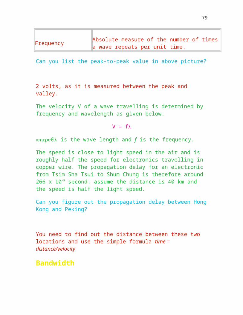
Can you figure out how many modems are required if multiplexer is not used?
Increases telecommunication line utilization Transparent to the end users (no specific software required)
Cluster/terminal controller
This is also termed terminal multiplexer and is used to increase efficiency of the high speed line and to offload the terminal handling mechanisms. Logical connection is introduced rather than physical connection.
Terminal Connection Methods
Figure shows various connection methods through PSTN(switched line), leased line or direct-wire to the computer at a short distance:-
Comparison amongst all the configurations
Type Advantage Disadvantage
Point to point simple inefficient
Multidrop
fully utilizes the bandwidth of the transmission line by supporting a few more communication devices
requires additional control software to send/receive messages from the master unit to individual slave units
Multiplexing a reasonable compromise between cost and line efficiency
requires a pair of multiplexer to assemble/reassemble the messages from individual terminals
Cluster controller maximize the use of high speed line
relatively expensive to install a controller
79

Communications Devices
Modem
Modems are devices that convert a signal into an analog tone for transmission on an analog network and demodulate that analog signal into a digital signal on the receiving end as shown in Figure . Modems are broadly classified into asynchronous and synchronous type.
Asynchronous Modem
The characteristics of Asynchronous modem are:
Operate at lower speeds when compared to synchrnous modem, 64 K bis/s No transmit or receive clocks (Data rate is configured by the user and is sampled by DTE) Clocking on data, the receiver must configure to sample the incoming data Variable data rates (from 50 to 56K bits/s) Usually use FSK modulation for low speed device and PSK for medium speed device. Usually used for interactive terminals
If the incoming data rate is 2400 bps and the receiver is configured at 4800 bps, what will be the result?
Synchronous modem
The characteristics as shown in Figure are:
Operate at higher speeds (up to 64 kbits/s) Require transmit and receive clocks to trigger the computer to process the data Data derived receive timing (driven by the internal or external clock, which depends on the source of clock. If the clock source is from modem, it is called external clock or vice versa) Fixed data rates as it is controlled by the clock Usually use Phase Shift Keying (PSK) or QAM (combining the amplitude and phase together) modulation
80

Other factors to be considered for selecting the right modem include the following:
Whether it is switched, leased or multidrop for the modem Full duplex or half duplex transmission mode Two wire or four wire between a pair of modems Maximum available transmission speed Availability of error recovery and data compression
4 wire full duplex is usually leased by companies for high speed transmission.
CCITT (ITU-T) Recommended Modem Types
CCITT Type
Description
V.17 Asynchronous; 14400 bit/s; Full duplex; 2-wire; dial-up; FAX send and receive
V.21 Asynchronous; 300 bit/s; Full duplex; 2-wire; dial-up; low speed
V.23 Asynchronous; 1200 bit/s; Half-duplex; 2-wire; dial-up; full-duplex or full-duplex; 4-wire; leased; low speed
V.26 Synchronous; 2400 bit/s; 4-wire; leased lines; medium speed
V.27 Synchronous; 4800 bit/s; FDX; leased lines; 8 phase @ 1800 HZ; high speed
V.29 Synchronous; 9600 bit/s; auto-equalized; FDX; 4-wire lines; high speed
V.32bits 12000 bit/s; FAX; 2-wire
V.34 28800 bit/s; FDX; 2-wire; high speed
81

V.34 33600 bit/s; FDX; 2-wire; high speed with data compression
V.42 error correction
V.42bis data compression: therefore v.34 modem using v.42 would transmit 28800*4 = 115200 bps
MNP2-4 error correction
MNP5 Data compression
V.90 receiving at up to 56K bit/s and sending at up to 31.2K bit/s; FDX; 2-wire; very high speed
X.20 Interface between data terminal equipment and data circuit-terminating equipment for start-stop transmission services on public data networks
X.20bis V.21-compatible interface between data terminal equipment and data circuit terminating equipment for start-stop transmission services on public data networks
X.21
General purpose interface between data terminal equipment and data circuit-terminating equipment for synchronous operation data networks. X.25 level 1 uses X.21 as the physical layer to send/receive data bit-by-bit.
Example of a 56Kbps modem
Zoltrix 56K is used as an example to demonstarte the operating speed, features, FAX and voice support only. You don’t have to memorise the details as it is product oriented. The Zoltrix 56K Fax/Data/Voice with Speaker Phone Modem (internal) Model FMVSP56i3 and (external) Model FMVSP56e3 are a virtual communications center. Download data from compatible sites at an incredible 56,000 bps* for fast Internet and LAN access and provide up to 33,600 bps uncompressed data transmission over conventional telephone lines, using the V.34 protocol. The “Dual-Mode” modem can automatically select either V.90 or K56Flex. There is no need to update the modem to V.90 when the userr ISP upgrades from K56Flex to V.90. With “Dual-Mode”, the modem automatically
82

connects at K56Flex or V.90, to achieve download speeds nearly twice as fast as any conventional analog modem.
The Zoltrix 56K Fax/Data/Voice with Speaker Phone Modem (internal) Models FMVSP56i3 and FM-VSP56e3 also supports Flash ROM. This means that whenever there is an update to the modem code, the user can download it from the internet, and upload the new code into the modems Flash ROM.
The FMVSP56i3 and FM-VSP56e3 also provides 14,400 bps send/receive fax. The fully-integrated phonebook ensures easy-to-use faxing. The user can even “broadcast” your faxes to multiple recipients, schedule fax transmission, or forward them to another number.
The simple and intuitive interface even allows quickdialing of up to 80 entries. Incoming calls are automatically detected as fax, data or voice. And any detected voice call is routed to the voice mail module which allows the caller to leave any messages in individual mailboxes.
The incoming voice call can also be monitored to allow the user an option to record the message or by a simple click of your mouse, to answer the call. And with Caller ID, the user can tell who is calling before answering the call. This kit includes the fax/modem, easy-to-read manuals, a microphone for hands-free Full Duplex speakerphone operation along with fax, data, voice and speakerphone software.
The Zoltrix 56K model FM-VSP56i3 and FM-VSP56e3 uses the Rockwell 56 K chipset, and incorporates all of the industry standard protocols (V.90, K56Flex, V.34+, V.34, V.32bis, V.32, V.22bis, V.22, and V.21) with speeds ranging from 56,000 bps* down to 300 bps.
On the Fax side it communicates with all ITU-T Group 3 FAX machines and is compatible with ITU-T V.27ter and V.29, V.17, T.4 and T.30.
The software bundled with the Zoltrix 56K modem includes Cheyenne’s Bitware lite or Thought Communications Faxtalk. Also with the FREE Internet Software and extensive on-line service package you’ll be surfing the net, sending e-mail messages and going on-line in no time at all.
Fax Features include" Send and Receive Fax Messages to or from any Group 3 Fax Machine/Fax card", “Automatic Fax/Data Detection” etc. Modem Features include “Send and receive files, exchange E-mail and access online services”, “Supports ASCII, Xmodem, Ymodem, Zmodem and Kermit Data transfer
83
protocols” Voice Mail Features include “Automatically detects and routes incoming voice, fax and data calls to the proper module of integrated fax, data or voice”, “Creates up to 999 voice mailboxes, each with a personalized mailbox greeting” Speaker Phone Features include “Turns your computer into a full-function speakerphone (speakers required)”, “Places and answers telephone calls directly from your computer”. Technical specification include “Caller ID (Requires Caller ID service from the phone compay)”, “Data throughput up to 224,000 bps”, “Max DTE rate of 230,400 bps”, “Modem Operating Modes”, and
V.90 56,000 bps* receive/33,600 bps* send K56flex 56,000 bps* receive/33,600 bps* send V.34+ 33,600/31,200 bps V.34 28,800/26,400/24,000/21,600/19,200/16,800 bps V.32bis 14,400/12,000/7,200 bps V.32 9,600/4,800 bps V.22bis 2,400 bps V.22 & Bell 212A 1,200 bps V.21 & Bell 103 300 bps V.29 & V.27ter & V.17 Fax Transmission 14,400/9600 send and receive; Group III Send and Receive fax compatible V.42 & MNP 4,10 Hardware based Error Correction V.42bis(4-1) & MNP 5(2-1) Hardware based Data Compression
For details, please refer to “http://www.zoltrix.com”.
If the distance between two computers is short, it is preferable to replace the modems by a single Modem Eliminator which provides all the required clocking and interface lead protocol. This will significantly reduce the implementation cost especially when synchronous mode is used. When two ports are operating at asynchronous mode such as DEC DDCMP, it is simply to twist the Transmit and Receive pins.
What is the difference amongst X, V and I series?
X refers to the communication components in digital network, V in analog network, and I in Integrated Services Digital Network.
84

Multiplexers
The function of a multiplexer is to combine several low-speed data either from terminals to computer ports to a high speed communication channels over long distance. It is extremely cost-effective when a pool of terminals are required to connect to respective computer outputs to run different application programs through a commonly shared channel as shown in Figure . The advantages offered by using multiplexing include:
Channel shared by multiple devices Reduces line costs Reduces modem costs Increased line utilization Transparent - this configuration is invisible to the users.
There are currently two types of multiplexing techniques namely time division multiplexing and frequency division multiplexing.
Frequency Division Multiplexing
It is to divide the whole frequency bandwidth into a number of sub-bandwidths to be used by individual users. The characteristics are:
Partitions bandwidth into parallel channels Guard bands (frequencies) to prevent subchannel interference Subchannel bandwidth allocated is proportional to speed Channel capacity is limited by the bandwidth
Time Division Multiplexing
Figure shows the comparison between time division multiplexing and frequency division multiplexing. Here, for TDM, the channel is shared amongst the signals and for FDM, a cable is divided into a number of sub-channels. The characteristics are:
Digital techniques to support a few communication devices Partitions time into slots to different devices Samples multiple lines Guard time is provided to prevent interference Forms composite digital output between a pair of multiplexer Requires modems for analog channels if the distance is over the RS232C
85
limitation
Figure shows how a pair of TDMs work. The transmssion is divided into a number frames each of which is used to support different devices.
Under what condition, a pair of modems is required.
For long distance communication.
Time Division Multiplexing is further classified into:
Synchronous- means the transmission is synchronous between data and clock Bit TDM- sending the data as a series of bits Character TDM - sending the data as a series of bytes Asynchronous - there is no clocking signal and the transmission of data is random Statistical TDM
Both Bit TDM and Character TDM use fixed frame format, which in certain cases will not optimize the channel usage when the traffic for each device is significantly different. The Statistical multiplexer is designed to eliminate this wastage. In this device, the allocation of bandwidth is dynamic. Channels that are idle are simply skipped as shown in Figure .
Micro/Mainframe Link
Three are three types of micro/mainframe links:
terminal emulation
data downloading and uploading
distributed processing
86

Terminal emulation: a terminal emulation software is run in a micro so that it presents to the mainframe as a particular terminal that the mainframe supports. Data from mainframes are downloaded to micros for particular processing, then the results are uploaded from micros to mainframes. Distributed processing is different from the above two methods as data are processed by both the micros and mainframes; this is hard because of the immense number of computers and software that the complete integration process should consider.
Communications front end processor
It is designed to relieve the host’s loading and is dedicated to support various communications protocols and multiple physical lines without borrowing machines cycles from the host as shown in Figure . It performs the scanning and the byte assembly/disassembly process and passes the data to the host by interrupting the host. The characteristics are:
As there may be a number of computers and terminals in a network, each of them should be assigned with a unique address so that messages can be directed to the right destinations; this also implies every message has been tagged with the destination node’s address. Two communication nodes may be connected by more than one way; thus, a decision must be made to choose one of the communication paths. In order to ensure the communication is fine, messages are usually packed with control information for error detection (or sometimes for error recovery as well) and the encoding and decoding of this control information take processor time. To reduce communication cost, messages are often compressed before it is transmitted; for data security, messages are sometimes encrypted before transmission and decrypted at the receiving end.
as one can see, there are a number of extra workload when data is to be communicated; to relieve the host processor of communications-related tasks, front-end processors or data communications controllers are introduced.
87
Protocol converter
It is designed to form a bridge between two incompatible communications protocols. One of the common application is in Synchronous to Asynchronous conversion. A/S-3 manufactured by Black Box is used for connection of asynchronous terminals, printers and personal computers onto an IBM BSC or SNA/SDLC network. Figure shows the connection. Here, three asynchronous terminals are connected to an IBM Mainframe 3090 through this converter.
Data Switch
This is designed to connect a few terminals to computers. Connections can be made at each user’s terminal such as Devecon data switch. It is extremely cost-effective when different brands of incompatible computers are used. Figure shows how a switch is used to conncet between a printer and two PCs. This is a manual switch set by the user.
Patch panel
It is principally similar to a data switch except it is operated manually. The connection has to be made by using a short wire jumper. By default, the DTE and DCE port is connected together. The user can also connect any DTE to one of the DCE ports at will. So long as a wire jumper is presented, the default connection between two adjacent DTE/DCE connection is broken.
Type Channel 1 Channel 2 Channel 3 Channel 4 Channel 5 Channel 6 Channel7
DTE
DCE
Monitor
88
Figure shows how a patch panel works. Here, a patch panel is connected to a few terminals locally. The user can change the connection by re-connecting the short-wire jumpers.
Private branch exchange
PBX is a telephone exchange. The latest PBX cannot just support voice but also data. The terminal user can connect to a specific computer by calling the associated telephone number. As cabling cost could be expensive, efforts have been made to effectively use the existing telephone network. Figure shows a Data switch is used to conncet a mainframe and a few terminals through a set of leased lines. The characteristics are:
a PBX is a computer that electronically connects computers and terminals much as telephone operators manually connected telephone lines on the old PBX switchboards two principal types of PBX are used: one type was designed mainly for voice transmission (in analog form) with the capability of transmitting digital signals. the other type is designed for digital signal transmission with the capability of approximating analog signal by digital signals using built-in codec. several advantages of the digital approach over the traditional approach: (1) control data encryption can be easily accommodated with digital signals, (2) TDM can be applied for handling digital signals easily, (3) control signals are inherently digital and can easily be integrated into a digital transmission path, and (4) digital PBX can take advantage of low-cost LSI and VLSI components.
Self-examined Questions
Short questions
Power stations are usually linked up with microwave, explain why several 100-pair submarine cables are still required.
89
List THREE advantages and disadvantages of Frequency Division Multiplexing.
List TWO advantages and disadvantages of Statistical Time Division Multiplexing
True or False
Telephone wire can carry more information than a coaxial cable
Coaxial cable supports video signals only
Optical fiber relies on electronics to carry information
Point-to-point configuration is only valid in terminal to host communication
Multidrop configuration can reduce the line cost for low volume traffic
For band limited signal, a guard band is required for timing division multiplexing
++/
90
Chapter Five
System Architecture
This chapter is about the ISO/OSI reference model, a seven layer model for
computer communication. Upon completion of this chapter, you should
List the layered Architecture
Understand the ISO/OSI model used in data communications
Understand the differences in data communications model amongst various computer manufacturers
Network Architecture
Terminologies
Terms Description
DCE
Data Circuit Equipment such as modem in analogy network or Network Terminating Unit in digital network. It is regarded as the boundary of a network. Please note that a minicomputer can be a DCE if it is located at network boundary.
DTE Data Terminating equipment such as computer port or computer terminal in a network
HTTP HyperText Transfer Protocol, the rule the browser uses to transfer hypertext documents from server. Remember the process creation in Semester A. The server (Unix based) once receives a request from the browser through the
91

Internet will spawn a child process to respond this request.
Network Architecture
Is a formation of a structure to describe what things exist, how they operate and what form they take. It is a combination of hardware, software, protocols, network topologies etc. A typical example is the computer networks being used at CityU’s Computer Centre
IP Internet Protocol, used in network layer
Protocol It defines how network components establish communications session, exchange data and then terminate the service gracefully.
OSI Open Systems Interconnection standard, is now widely used in defining the network architecture
SNA System Network Architecture, used by IBM to link up various hardware/software products
TCP Transmission Control Protocol, used in the Internet between end to end communication, a conncetion oriented protocol
UDP User Datagram Protocol, used in the Internet between end to end communication, a connectionless orientd protocol
Line Protocol
As described, a protocol is a set of rules governing two communicating parties to exchange information correctly. Regardless of computer type, if a protocol analyzer is hooked up in the transmission line to monitor the network traffic. Both parties must establish a communication session in order to exchange information. The following requirements will be observed.
92
Initialization and finalization procedures Data transmission procedures Sender and receiver designation (Equivalent to assigning the primary or secondary in IBM network) Transmssion error detection and subsequent handling
An example about directory assistance protocol between the caller and a telephone operator is used to elaborate the meaning as shown below:
Operator Caller Function
Can you suggest other examples that use the concept as mentioned?
Layered Protocols
Modern communications networks are using the concept of layered approach to provide more reliable and flexible services. This approach clearly defines the software and hardware interfaces between two layers using structural design. Modification to one of the layers will not impact the adjacent layers so long as the same interfaces are still maintained. The concept of layered design or levels of abstraction has been widely accepted as a good system structuring practice.
Each layer N as shown in Figure is defined by:
An interface defining the services it provides to layer N + 1 and above
An interface defining the services it requires from layer N - 1 and below
The protocol with peer layer
Additional advantages of using layering approach include:
Reduce design period as the whole network is broken into several manageable components that can be easily understood.
93

As each layer is well defined, modification to one of the layers to take advantage of new hardware/software technologies will not affect the whole network. It is more flexible for the equipment vendors to provide hardware/software services for a few lower layers.
Some manufacturers only produce a few hardware products that are used in certain layers.
The internal structures, mechanism, encoding, and algorithms used within a layer are not visible to other layers. This provides a way of hidding information. Alternative implementation for a layer can co-exist, providing opportunity for testing and reliability. The confidence in the correctness of a layered system is more easily established by testing and analyzing each layer in turn.
Only the lowest layer performs physical communications between two communicating devices. All other layers use virtual communications to pass information and control messages to the adjacent layers.
List the difference between virtual and physical communications as shown in Figure .
ISO/OSI Reference Model
ISO introduced a seven-layered Open Systems Interconnection reference model so as to provide protocols for different vendor’s/manufacturer’s products to properly communicate with each other. The ISO layered concept uses the clearly defined partitions to provide guidelines for the flow of data, control message etc. through each layer at each node. The characteristics of such a model are:
Use a reasonably small number of layers (7 only) Provide interfaces at points where the service description and number of interactions can be made small
94
Provide separation to handle functions that are clearly different in process and technology Group related functions. (Data link is used to provide error-free message.) Provide boundaries where interfaces can be standardized Provide appropriate level of abstraction Allow layers to be bypassed where appropriate
The ISO/OSI layers include:-
Application layer Presentation layer Session layer Transport layer Network layer Data Link layer Physical layer
Figure illustrates the OSI model through a subnet.
Explain why a subnet is included in this diagram.
Brief explanation for each layer
Layer Description
Physical layer Provides for the transparent bit transmission over the communications medium such as CCITT (ITU-T) V.24.
It involves four specification including mechanical, electrical, procedural and functional
Signal coding and encoding such as from digital signal to analogue signal
Data Link layer Provides an error-free environment to the network.
Keep check the frame sequence
95

Define unit of transmission such as framing
Proper procedure for access to communication medium
Handle error control and frame flow control
The higher layer messages will be embedded into frames
Network layer Specifies network routing and the communications between networks and also the interface of the user DTE.
Performs network congestion control
Transport layer Provides an end-to-end transport service and is designed to keep the user isolated from some of the physical and functional aspects of the network.
Multiplex messages from higher layer to network connections
Segmentation, blocking and message sequence
Error detection and monitoring of service quality
Flow control of individual connections of transport layer to network to match the requirement of costs
Transport services include virtual circuit, datagram and broadcasting
Session layer Provides for mechanism that would allow application processes to establish a session. A formal description is not yet available.
The interaction management establishes a two-way interaction or a two-way alternate
Presentation layer Responsible for the transformation of data such as data encryption
Developing three standards such as virtual terminal protocol, virtual
96

file transfer and job transfer.
Application layer Concerned with the support of an end-user application process
Satisfy data/information transfers such as the data base access
The functions distribution presented above represent a guideline only. Not all systems conform to such distribution. For example, IBM SNA has its own definition for each layer.
Other Network Architectures
Different computer vendors have been developing their own network architectures such as IBM and TCP/IP which are slightly different than ISO standard. The current trend is to migrate towards the OSI reference model to provide compatibility. Comparison among different vendors are given below:
Layer ISO IBM SNA
TCP/IP
Further Layer Principles
Each layer consists of a number of functional units called N-entities. The N-entities provide a set of services to the entities of the layer above. The layer above is called the service user and the layer below is called the service provider as shown in Figure .
Passing data from one layer to others, what extra information is added and where?
Header is added by each layer to the Protocol Data Unit(PDU) to identify the location of each layer. For example, a 3-byte frame header and frame trailer are
97

added to the frame by data link layer, and a transmssion flag as the frame delimiter is added by the physical layer.
Self-examined Question
Match OSI seven layers in column A to the description/characteristics in column B. Each column in A may match a few columns in B.
Column A
Column B
98

Chapter Six
Physical Layer
This chapter is about the characteristics of Physical Layer, the lowest layer
in the ISO/OSI reference model. Most of the network problems such as noise interference, incompatible cable connection and line disconnection come from this layer. This layer interfaces with outside world through transmission modem, LAN card, network terminating unit or direct connection with other computers. Transmission error detection, digital signal conversion and interfacing with various types of communications equipment are also done in this layer. Upon completion of this chapter, you should
Understand various definition of standards related to this layer
Identify the characteristics and role of physical layer
Understand the PC communications using 8250 UART communication chip
Physical Layer
This is the lowest layer in ISO/OSI reference model and is
concerned with the transmission of data from one point to another over the communications media such as telephone wires, satellite link, or coaxial cable. This layer is dealt with the physical data transmission and is therefore related to:
Type of transmission medium (Copper wire, air, optical fiber etc.)
99

The transmission media such as telephone cable are sometimes regarded as Layer 0.
Modulation and demodulation scheme (FSK, PSK, digital data). This is about the conversion of signals from digital to analogue or vice versa through the network. That is why this layer is designed to handle signal control between the communications port and the modem.
The signal controls (interpreted as procedural control) for full duplex, half duplex and multi-drop modems with internal or external clock are quite different. The data is passed from data link layer in the form of internal message with a data pointer. Physical layer then picks up the data pointer and prepare to send out the data prior to checking all the modem’s signals. This layer interfaces with leased line or switched line. Because of this diversity, the person who designs this layer (writing program to handle various signals) must acquire strong electronics background in various interfacing equipment.
Message switching techniques
There are FOUR specifications to describe this layer:
Mechanical specification such as socket layout, pin size etc. Electrical specification such as the electronic signals (in terms of voltage or current level) for certain pins. Functional specification such as timing or clocking signals Procedural specification such as the sequence of events required to effect the data transfer across a pair of modems. (For half duplex modem, In order to transmit data, the software must firstly raise the Request to send and wait for the Clear to send signal.
Do we need to do the same procedure for full duplex modem? (With appropriate communication software)
No, as full duplex will not check the CTS prior to sending data.
It is used to define the signalling interfaces between:
the DTE-to-DTE (To have two computers directly connected with each
100
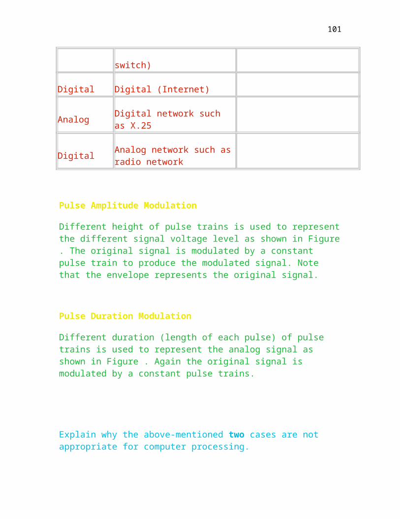
other without a pair of modems.) the DCE-to-DCE (The normal connection between two modems.)
DCE stands for Data Circuit Equipment and is the network boundary. Therefore, it could be a modem for voice grade network, a network terminating equipment for digital network or even a minicomputer.
Fill in the blank boxes in Figure using DTE, DCE or Data Link.
A typical network boundary Figure is an example of a fraction of network with DTEs and DCEs, please fill in the boxes using the terms DTE or DCE. This example tests your understanding the differences between DTE and DCE.
Can you explain why DTEs are circumvented by DCEs in Figure ?
Change of signal type
EIA-232-D and the ISO/CCITT
The EIA standard RS-232C (RS refers to Recommended Standard) was developed in 1969 in United States and is still widely used in industry. The latest version is called RS-232D. Using the above description, this EIA standards are also adopted by CCITT (Consultative Committee on International Telephone and Telegraph, this was renamed as ITU-T recently) and ISO (International Standards Organisation) to cover the following specification:
Characteristics CCITT or ITU-T/ISO Standard
Electrical CCITT V.28, Standards produced by CCITT to cover the electrical aspects similar to RS232
101

Functional CCITT V.24, Standards produced by CCITT to cover both functional and procedural aspects of RS232
Mechanical ISO 2110, Standards produced by ISO similar to the functions of RS232.
Procedural CCITT V.24
This is a 25-pin connector with data, control, timing and ground signal pins as shown in Figure . Not all of them are used for data transmission as the basic pins are three only, namely, Transmit (pin 2), Receive (pin 3) and Signal Ground (pin 7) only.
This standard allows for cable lengths of up to 15 meters at up to 20,000 bps. In practice, with better line quality such as low capacitance, longer lengths and higher rate are permissible. For instance, Category five cable for short distance can support up to 100 Mbps.
Not all the signals are required to perform the data transmission in actual application such as Ring Indicator is needed in dial-up modem.
Explain the function of Data Carrier Detect used in Figure .
It is used to detect whether any carrier wave used to carry data is presented in the transmission line, which indicates whether the transmission line is empty or occupied by the remote end.
The detailed description for each pin as shown in Figure is as follows:
Term Description
Data Set Ready This is a control signal from the modem to the DTE to indicate that the modem is powered on. For switched line auto-answer modem, this signal will not be activated until a DTR signal is
102
received from DTE.
Request to send
This is a supervisory signal from the DTE to the modem to indicate that a request has been made from DTE to permit data transmission. This signal is not required in full duplex modem. The physical layer will not send out the data kept in the buffer until a Clear To Send (CTS) signal is received from the modem. The time it takes to receive this signal is called turn-around time and is related to the propagation delay between two modems. This value is set by the user by use of AT (Advanced Technology) commands for Hayes compatible modem or hardware stripping. This turn-around time is required for half duplex modem to inhibit the other side to initiate data transportation.
Transmit/Receive Clock
This signal comes from the modem to the data terminal equipment to provide the correct timing to clock the data. This is primarily used in synchronous modem to provide a trigger to the physical layer to sample the data. Please note that, for asynchronous transmission, line speed is required to configure the computer port to sample the data once the start bit is received. On the other hand, for synchronous transmission, there is no such requirement to provide the line speed for external clock. The line speed is controlled by the modem which will generate a pair of clocking signals (Transmit and Receive from pin 24 ETC (External Transmit Clock) in RS232-D) to trigger the physical layer to sample the data value. Because of this, a user will dynamically change the line speed while a file transfer has started without causing damage to the software.
Receive data This wire carries the digital data from the modem to the data terminal equipment after demodulating the signal from the carrier. The idle voltage level is -12 volts.
Receive Timing
This signal from the modem to the data terminal equipment accompanies the data so that the terminal equipment knows when to sample the incoming data so as correctly interpret the data. This wire is used for synchronous modem.
Data Carrier Detect This signal is used to advise the DTE that the modem has locked
103

onto the received carrier and that it is ready to demodulate data.
Transmit data This wire carries the digital data from the DTE to the modem. (From computer port to another computer.)
Data Terminal Ready
This pin is used to indicate the computer port, DTE, is powered on. Once the physical layer is initialized by loading an appropriate software, it will enable this pin for leased full-duplex, half duplex and multi-drop modem, but not the switched line auto-answer modem.
Ring Indicator
This pin is used for switched line auto-answer modem and is extremely useful in synchronous transmission mode. Once an auto-answer modem receives a telephone call, the Ring Indicator will generate a sequence of pulse trains similar to the ringing signal to the computer port (DTE) to notify the physical layer that an incoming call is pending.
For Ring Indicator, physical layer will then raise the DTR and expects the DSR signal from the modem prior to sending or receiving data as shown in Figure with appropriate sequences.
For a typical asynchronous connection, only Transmit data, Receive data and Signal ground are required to connect a DTE to DCE. A set of secondary signals pin 12, 13, 14 & 16 of RS232C connection are used for monitoring purpose or emergency use in case the primary signals are stuck.
DTE-DTE (Computer to Computer port)
When terminals are connected directly to a computer port, it is necessary to cross over some of the wires in order to communicate properly. When two computer ports are connected running at synchronous protocol, either one should provide the correct timing or a null modem with proper timing
104
signals is required. Note that the detection of control signals is determined by computer software.
DTE A
DTE B
TD 2 2 TD
RD 3 3 RD
RTS 4 4 RTS
CTS 5 5 CTS
DSR 6 6 DSR
SG 7 7 SG
DCD 8 8 DCD
TC 15 15 TC
RC 17 17 RC
DTR 20 20 DTR
ETC 24 24 ETC
Draw the corresponding lines for IBM PC to IBM PC connection. and label the pin number and explain why only three pins are sufficient in this connection.
DTE-DCE
This is a normal configuration of the V24 interface between the computer port and modem. It therefore uses the straight through cable. That is to say there is no cable cross. Figure is a synchronous modem connection, which requires transmit and receive control to drive the signal data. Signal return path (Signal Ground), other control signals such as RTS are not shown in this connection.
105

Historic Development on IBM PC
In August 1980, IBM announced their first personal computer which used the 8-bit Intel 8088 microprocessor. It was configured as 64K of random access memory on the motherboard, which could be expanded to 256K by adding memory chips on the same board. The decision at this stage to use 64K instead of 640K is to reduce the cost and enhance the competition. The operating system at that time was DOS version 1.0 developed by Microsoft Corporation. Since then, IBM had manufactured different kind of hardware as listed in the following table
Year Hardware Processor Operating system
1981 Personal Computer 8088 DOS 1.0
1982 COMPAQ portable 8088 DOS 1.1
1983 PC XT 8088 DOS 2.0
1984 PC Junior 8088 DOS 2.1
1985 PC AT 80286 DOS 3.0
1986 PC Convertible 80C86 DOS 3.2
1987 PS/2 Models 60 80286 DOS 3.3
1988 PS/2 Model 80 80386 OS/2 1.0, DOS 4.0
1989 PS/2 Model 55 80386 OS/2 1.1
1992 80486 upgrade for model 70-A21
80486 DOS 5.0/Windows 3.1
106
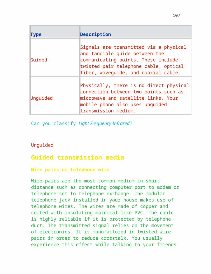
1993 80486 DOS 6.0/Windows NT
1995 Pentium DOS 7.0/Windows 95
1998 Pentium Pro (400 MHz)
DOS 7.0/Windows 98/Windows NT 4.+
The IBM AT (Advanced technology) was introduced to the marketplace in 1984 with some technological advances compared to XT. The PC architecture has been changed since its release in 1984. However, the way of communicating using serial communication chip is basically no major different, as it is still using asynchronous communciation even the line speed has been changed from 1200 bps to 56 K bps. The I/O ports are optional with serial/parallel adapter for RS-232C and printer. The first PS/2 model 30 was introduced to market in 1987 using 8086 processor chip. The model 80, a floor-standing model, is equipped with the 80386 processor chip operating at 16 or 20 MHz. Some of the hardware communication features are listed below:
Built-in RS-232C serial port Built-in bi-directional parallel port Built-in printing-device port
The intel 80286
This chip was introduced in 1982 and is a descendent of the 8086/8088 microprocessor. It is frequently called 286 rather than 80286. Some of the most important features of the 80286 are:
Sixteen Mbytes of physical address space One gigabyte of virtual address space A real address operating mode in which the 286 emulates and is compatible with the 8086/8088 CPU A protected virtual address to implement the advanced features of the 286 Multitasking support by providing a separate logical address space for each task (XENIX) It contains eight arithmetic registers, four index registers, four segment registers and eight general purpose registers
107
Communication hardware
By definition, computer communication refers to the exchange of data between computers and terminals. This covers the data transmission to any type of peripheral equipment (keyboard, disk drive etc.) and through and any type of internal or external, wired (telephone line) or wireless (satellite link) data path. The discussion of this section concentrates on the serial port only.
Serial communications
It takes place by transmitting and receiving data in a stream of consecutive electrical pulses that represents bits. The EIA (Electronic Industries Association) has recommended several standards for serial communication such as:
RS-232-D (Similar to V.24 developed by CCITT) RS-422 RS-423 RS-449
RS in this designation refers to Recommended Standard. Amongst all the standards, the simplest to implement and most used serial communications standard is RS-232-D. Most personal computers are asynchronous and these is no technical reason exists why a PC cannot be synchronous. Many products in the form of adaptor are entering the marketplace that provide synchronous capabilities such as SDLC, Bisync and even X.25. Many microcomputers house the modem within the cabinet. These devices are called plug-in modems or on-board modems and can free workspace at a crowded desk and provide a portable modem for the traveler. In the RS-232-D protocol, the transmission and reception parameters are selected from a range of standard values as given below:
Type
Description
Baud rate
50, 110, 300, 600, 1200, 2400, 48000, 9600 and 19200
Data bits
108

5, 6, 7 or 8
Parity bit
Odd even, or no parity
Stop bits
1, 1.5 or 2
RS-232-D defines data terminal equipment and data circuit terminating equipment (sometimes, it is called communications equipment). Based on this standard, DTE designation refers to both terminals and computers (serial port in IBM microcomputers) and DCE refers to modems, transducers and other devices in Figure .
Connectors and wiring
The RS-232-D standard requires a hardware connector called DB-25 (D-shell connector with 25 pins). Not all the IBM serial ports use the DB-25 connector. For instance
PC junior uses a 16-position BERG connector PC AT Serial/Parallel Adapter uses a 9-pin connector
The function assigned to the three connectors are tabulated below:
Connector Function Code name Direction
DB-25 DB-9 BERG
1
B2 Protective Ground
G
2 3 A4 Transmit Data
TD Output
3 2 A8 Receive data RD Output
4 7 A3 Request to RTS Output
109
send
5 8 A7 Clear to send CTS Input
6 6 A6 Data set ready
DSR Input
7 5 B1 Signal Ground
SG
8 1 A5 Carrier detect CD Input
20 4 A2 Data terminal ready
DTR Output
22 9 Ring
indicator RI Input
Figure shows various wiring connection diagram.
Wiring Diagram
Apart from the conventional wiring diagrams between computer & modem and computer & computer, Figure in previous page shows the wiring connection between two PCs. Null modem refers to the connecting scheme between two DTEs.
Serial communication controller
The fundamental element of the serial port is an IC called 8250, universal asynchronous receiver and transmitter (UART). An internal block diagram showing the elements in the serial communications controllers are given in Figure . The operation of this chip is summarized below:
The transmitter portion of the controller converts an 8-bit data value placed by the processor in the adapter’s output port, into a serial bit stream
110

The bit stream is formatted according to the RS-232-D protocol.
During the transmission, the controller inserts the necessary start, stop and parity bits.
While receiving a character, the controller can decode an incoming bit stream and place the data byte in the adapter’s input port
During the reception operation, the chip uses the start, stop and parity bits to synchronize the transmission, to identify the data bits and to check for transmission error
All the serial communications controllers used in the IBM microcomputers are capable of full duplex operation. That is to say while sending the data, an IBM PC can also receive the data from the other side.
The 8250 UART uses 10 registers accessible by the programmer to control the data transmission. Details of each register are given below:
Register Name
Port Address Function
COM1 COM1
If the serial communication controller is mapped to the addresses from 3F8 to 3FE in hex, it is said to be configured as communication port #1 (COM1:). This applies to COM2, COM3 or COM4 as well.
During the BIOS initialization routines, it stores the base address of the first serial port at memory locations 400H in the BIOS data area. If two or more ports are implemented, their base addresses are stored at memory locations 402H, 404H etc.
111

Different baud rate can be obtained by programming the baud rate divisor. Some figures for PC-AT operating at clock speed 1.8432 MHz are given below:
Baud Rate
Desired Divisor in HEX
% Error
The value is obtained by use of following formula:
Desired divisor = Clock speed/(16* Baud rate desired)
Where the clock speed is 1.8432MHz for IBM AT.
What is the clock speed of 80486/P5?
Percentage of error will not contribute transmission error during data transfer, as this minor discrepancy can be tolerated by the receiver.
There are four types of interrupts namely:
Received data available interrupt Transmitter holding register empty interrupt Receiver line status interrupt. A line status register 3FD in hex is used to keep check the quality of received character. Modem status interrupt. A modem status register 3FE in hex is used to keep check the status Ring indicator, Clear to send etc. Theses interrupts are controlled by the interrupt enable register (IER) starting from bit 0 to bit 3. In addition to the interrupt, there is a line status register located in 3FD in hex to keep check the quality of received character.
Type
Description
112
Data ready Data is available in the receiver data register if the bit position 0 of line status register is set to 1.
Overrun error Data is not removed in time from receiver data register if the bit position 1 of line status register is set to 1.
Parity error
A character is received in the receiver data register with incorrect parity if the bit position 2 of line status register is set to 1.
Framing error
A character is received in the receiver data register without valid stop bit if the bit position 3 of line status register is set to 1.
Break Interrupt indicator
The receiving line is in spacing state if the bit position 4 of line status register is set to 1. Normally, the receiving line is in idle state.
The line control register located in 3FB in hex is used to program the transmission line, which includes character size, parity detection method, and the size of stop bit.
Bit position Description
0 and 1 It is used to control the word length. 00 is for 5 bits
2 It is used to set the number of stop bits. If it is set to 1
3 This bit is used to set the parity bit. Parity is enabled
4 This bit is used to select the parity type. Even parity is selected if this bit is set to 1 else odd parity.
113

The following is the program segment to check the line status
MOV DX, 300H; base line address for COM1:
MOV DL,3FDH ; load the line status register offset
IN AL,DX ; Read byte
TEST AL,00011110B ; text error bits 1, 2, 3 or 4
JNZ ERROR ; Yes jump to error handling routine
TEST AL,00000001B ; Check whether data is ready
JNZ RECEIVE ; Yes and take action
A modem control register 3FC in hex is used to control the line signal. This include the Data Terminal Ready and Request To Send. The handshaking technique used by IBM includes hardware and software handshaking:
Hardware handshaking, This protocol is designed for a connected printer. It uses either DTR or CTS to control the flow of data. If the printer is busy, it will drop DTR to inform the 8250 so stop sending further characters until this signal is resumed. Software handshaking. This protocol uses XON/XOFF to control the flow of data between two PCs. This method is almost an industry standard.
The transmission line speed of PC is controlled by the speed of processor and the software program to detect the availability of character in the data register.
The frequency with which the program must monitor the line for new data can be estimated by dividing the baud rate by the number of bits in each character transmitted. For a typical 10-bit character (including one start bit, one stop bit, one parity bit and seven data bit), it takes one-tenth time to monitor the line. Say for example, 4800 baud rate will have to monitor the communication line at a minimum frequency of 480 times per second to avoid the reception errors. This leaves the CPU with less than 1/480 of a second to store, display and manipulate the data. If interrupt subroutines were written to handle the receipt of data, it needs to go through extra steps before loading the data into the memory. A faster method is to use polling routine to repetitively keep check the
114
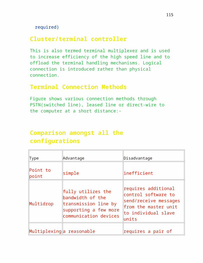
line status register to process the data. Using this method, the transmission line speed can be extended beyond 30,000 bits per second.
Using two 386 PCs write a simple C program to perform file transfer and find out the maximum transmission speed that could be reached using either Interrupt or Polling method.
AT Commands for Modem
Modem Commands
The modem supports the standard and extended Hayes* AT command set. The AT prefix (also known as the Attention Code), signals the modem that one or more commands are to follow. These commands are industry standard language used to communicate with the modem. The modem is always either in the command mode, or the on-line mode. The modem starts up in command mode when it is first switched on. Commands are only accepted by the modem when it is in command mode. Commands input when the modem is on-line, are treated as data, not as commands. Commands may be entered from the terminal mode of most communications software packages.
Settings made via AT commands are automatically reused by the modem until another command is received to change them, or the modem is turned off
Setting Up the Command Line/H3
All commands except two, must begin with the characters AT. The two exceptions are the escape sequence (+++), and the repeat command (A/). The command line prefix (letters AT) and the command sequences which follow, can be typed in upper case, or lower case, but case must not be mixed. More than one command can be typed on one line, separated by spaces if you wish for easier reading. The spaces are ignored by the modem’s command interpreter. The command line buffer accepts up to 39 characters including “A” and “T”. Spaces, carriage return, and any line feed characters do not go into the buffer, and don’t count against the 39 character limitation. If more than 39 characters are entered, or a syntax error is found anywhere in the command line, the modem returns an ERROR result code, and the command input is ignored.
115
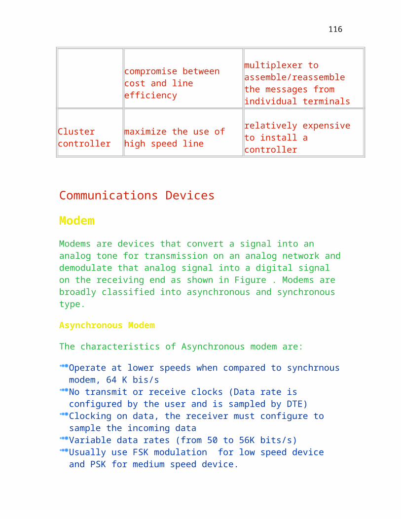
Basic Commands/H3
With the following basic AT commands, the user can make calls directly, select the dialing method (tone or pulse), control the speaker volume, and perform a number of other basic modem operations. Some are as follows:
Command Description
Making a Call
To place a call use the following dial modifiers
ATD 27888639 (Note this is my office number, don’t try this)
The modem dials the telephone number 27888639 and then waits for a carrier from a distant, or remote modem. If no carrier is detected within a given time (as defined by the initial settings in S-Register 6), then the modem automatically releases the line and sends a NO CARRIER result code. If a carrier is detected, the modem gives a CONNECT result code and goes on-line, allowing communications with the remote modem. The connection between the two modems ends when any of the following occurs causing the modem to hang up, return to command mode, and send the NO CARRIER response.
The local modem loses the carrier signal from the remote modem. The Hang Up command (H) is sent. The DTR interface signal is dropped between the local DTE and modem when the &D2 or &D3 command is in effect.
This command restores the factory default settings, dials, using tones, a 9 to access an outside line, pauses briefly, then pulse dials the number 27888639.
AT &F1DT9,P27888639
Examples
The escape sequence causes the modem to go to the off-line command state from the on-line data state. After this escape sequence, the modem can accept
116

user’s AT commands. The escape sequence consists of three escape code that is defined by S-Register 2 (default value: decimal 43(+))
Do not enter any character before and/or after the “+++” for a guard time specified by S-Register 12 (default: 1 second). The duration between escape codes must also be within the guard time. After the modem recognizes a valid escape sequence, an “OK” result code is returned. If an escape sequence is valid, the escape code is transmitted to a remote modem. The ATO command is used to go back to on-line data state.
ATD 27888639 [enter]
CONNECT 28800
[data] [——]
( 1 sec pause )
+++ (Without 1 sec pause between escape codes)
( 1 sec pause )
OK (On-line command state)
ATH0 [CR] (Disconnect the line)
OK
This command resets the modem and recalls the stored configuration as defined at power on time.
Zn (Modem Reset)
Z0 — Reset and recall stored user profile 0.
Z1 — Reset and recall stored user profile 1.
This command displays the current active configuration, stored user profiles, and the first four stored telephone numbers. Applications may change these profile.
&V (View Configuration)
117

Figure shows the connection to CityU’s Link Plus to access the Internet service. The AT commands include ATZ, AT10, ATTD2xxxxxx and waits for the connection..
Serial Port Control
The modems.com 28.8(V.34) / 14.4 Kbps Data/FAX Modems can determine the speed, parity, and stop bits from the serial port connection. The modem automatically detects the serial data speed between 300 and 115,200 bps with the following formats:
Data Length Parity Stop Bits Total Length
7 None 2 10
7 Odd 1 10
7 Even 1 10
7 Mark 1 10
7 Space 1 10
8 None 1 10
8 Odd 1 11
8 Even 1 11
The modem also has the capability of automatically adjusting the baud rate to the internal serial port to physical carrier speed. The user application must adjust the baud rate of the internal serial port to it by detecting carrier speed after CONNECT xxxx message. This command setting is valid for reliable (error corrected) link and normal mode connections. The baud rate adjust feature is always active for direct mode connection.
118

Other Recommendations
X.20 and X.21 Recommendation
So far, we just mentioned the communication standard over voice graded network. For digital networks such as X.25 packet switching network, X.20 and X.21 are another interface standards which have received considerable attention in the industry since being approved in 1976. Recommendation is made to define the interface for asynchronous interface which is similar to V.21. Recommendation X.21 defines the interface for synchronous operation as shown in Figure . X.21 is a 15-pin connector. However, only eight lines as shown below are required. These recommendation will improve the performance as the ready-for-sending signals which are used in V series are not required. X.21 is the equivalent physical layer for X.25 and is enhanced with byte timing to synchronize the receipt of character. The functions of each pin are:
Signal Description
T Path for signal transmission
C Control data flow and call request. It is always on for leased line. This signal is equivalent to request to send in RS232D.
R Path for signal reception. This path is equivalent to receive in RS232D.
I Provides status indication from DCE to DTE
S Provides timing to the DTE signal timing bit
B
Provides byte timing. It will send out a signal once a byte is received.
119

EIA RS-449/RS-422/RS-423
As RS-232 standard is limited by the distance and speed, other standards as given below are later adopted to replace it. RS449 corresponding to CCITT V.35 is a 37-pin connector and supports transmission rates up to 2Mbps with cable length to 60 meters. It defines both mechanical (pin and plug configuration) and procedural (signal descriptions) aspects similar to RS232. The electrical specifications (balanced or unbalanced circuit) are defined by RS422 and RS423 respectively.
RS-422 equivalent to CCITT V.11 defines balanced electrical circuits. The binary signals are transmitted using a pair of signal wires. As a result, there is no negative impact in adverse condition like being hit by a high voltage and the data rate could be maintained with better reliability. RS422 allows transmission rates up to 10Mbps and distances up to 1000 meters between DTE and DCE interface.
RS-232 is also an unbalanced electrical circuit as the transmit and receive data are referenced with respect to the same return path. The use of twisted pair can cancel the cross talk produced by signal passing through the wire.
RS-423 equivalent to CCITT V.10 defines unbalanced electrical circuit. Like RS-232, it sends or receives the binary signals over a single wire and uses a single common wire for return path.
The electrical voltage levels are defined by:-
-0.22 to -6 volts is a mark or off (Binary 1) +0.2 to +6 volts is a space or on (Binary 0)
Current Loop
Current loop is an older technology to extend the physical distance up to 300 meters. It uses the current signal, presence of current signal or absence (no current), to represent binary 0 or 1 (mark or space) instead of voltage level in RS232D. The most common current values are 20 mA and 60 mA. This transmission method could support half or full duplex, which requires 2 or 4 wire connection as shown in Figure . Here, the active device will deliver the current while passive device accepts the current to interpret the data streams.
120

Device isolation could be achieved in this method through photo optical couplers.
Current loop cannot extend the line speed, as it is limited by the processing power of software program to read the data. Noise immunity is better than RS232 connection, as it uses a pair of wire to send data. In case there is a noise, it will be cancelled by this pair of wires.
Example of NT 4.+
To hire a 64K bps leased line from Hong Kong Telecom costs around 2000, which, of course, depends on the distance and the line speed. The current modem speed operating locally at 56 Kbps. The use of switched line costs less than 100 as the cost is simply the rental line cost. However, it has the disadvantage of line dropping. That is to say, if it is used for server connecting to ISP, the line might be disconnected as a result of interference on regular basis. This can be resolved by NT 4.+, as it has the capability of re-dialling to the remote to recover the line disconnection. It is achieved by regular poll the remote and in case there is no response, it will drop the line and re-dial. As a result, it becomes a semi-permanent leased line operating at 56K bps at a cost of 100, which is less than the hire of leased line as shown in Figure . NT can support up to four switched lines offering the total speed of 224K bps. The speed is still less than the IMS service offering a 1.5 M bps using the set-top box for Interactive TV (ITV).
Why not request the modem to check whether the line is broken?
The modem even can detect whether the line is broken is unable to memorise the telephone number and redials it. It should be up to higher level, not the physical level, to decide whether to re-dial or because of disconnection.
Self-examined Questions
True or False
The RS-232-D is defined for asynchronous modem only.
121

The maximum speed defined over the RS-449 is 10 Mbps.
The maximum speed defined over the RS-232-D is 20 Kbps.
The advantage of using current loop is its higher speed.
For full duplex IBM PC to IBM PC connection, at least four wires are required.
Short Questions
What is the function of the 150 ms turnaround time for a half duplex modem (ie. time difference between RTS and CTS going on)?
How to decide which communication device (DTE/DCE) transmits the data first?
What is the function of Data Terminal Ready or Pin 20 in RS232C connection?
What is the function of Request to Send or Pin 4 in RS232C? Explain why computer will not check this pin status for full duplex modem.
122

Explain why four specifications are needed to specify the requirements of the physical layer.
Can we configure a null modem to have different transmit/receive clocks?
Yes. In this case, transmit speed is different from receive speed.
Explain why electrical balanced circuit can support higher transmission rate.
It uses two wires instead of single to transmit or receive data in order to cancel the crosstalk due to high frequency.
123

Chapter Seven
Data Link Layer
This chapter is about various protocols being used in data link layer which is
the second lowest layer in ISO/OSI reference model. The protocols are generally classified into byte oriented and bit oriented protocols. The former protocol is the oldest technology and has been widely proved to be a reliable protocol for low speed low volume data transfer while the latter protocol is more efficient in data processing. Error detection and correction is done in this layer by re-transmitting the error frame. Upon completion of this chapter, you should:
Understand the functions of data link layer
Identify the structure of Bisync frame or block
Understand high level Data Link Control Procedures
Data Link Layer
This is the second layer principally responsible for sending and receiving the data in an error-free environment. In addition, it also maintains the data flow gracefully and is able to correct the sequence of transmission in case a distorted frame is detected. The functions provided are summarized as follows:
Frame Flow control, To prevent the sender from sending too fast. For example, RNR in SDLC will be sent by the receiver if the receiver hasn’t finished processing the previously received frames. It is required due to speed mismatch between two communicating parties as shown in Figure .
124

One party may be temporarily incapable of handling the current traffic load. For instance, due to temporary hardware problem, buffer space depletion, sudden processor load demanded by other functions.
Error Control and Detection, To maintain the frames being transmitted/received are in sequence and to make sure the frames haven’t been distorted due to transmission error. Link awareness, To monitor the link conditions and ensure the other end is still alive. For IBM machines operating as a secondary station, a 32 second time-out event will be forwarded to upper levels in case there is no activity in the link either due to the line or equipment failure. As a primary station, it will repetitively poll the secondary stations for a certain configured time-out period.
The data link peer parties may reside in a host-node configuration, or a node-node configuration as shown in Figure . The host-node refers to the interface between the Data Terminating Equipment and the network boundary(DCE in this diagram). The frame size between host-node and node-to-node may be varied, as a result, the frames may be fragmented (break into a few smaller frames) and reassembled (combine a few smaller frames into a larger frame) while traversing along a pre-determined transmission path.
Explain why data link layer is concerned about frames between two adjacent nodes.
It is error-free data transmission between two machines.
The block diagram indicating the relationship between network layer and physical layer is shown in Figure .
Additional frame header embedding the physical address of recipient, one control byte, and frame delimiter are added to the Level two frame. The transmission is carried out by the physical layer using synchronous/asynchronous data transmission. A transmission flag is added to the frame by physical layer as well.
125
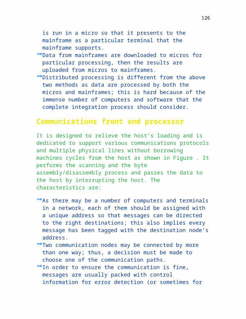
Hundreds of different link protocols are used by data communications in industry. A few examples are given below:
High Level data Link Control (HDLC: ISO). It is also the superset of SDLC, LAP and LAPB. That is to say, HDLC covers SDLC (used by IBM), LAP and LAPB (used by X.25) Fax transmission uses the modified HDLC which is more complex. Synchronous Data Link Control (SDLC: IBM) It is the proprietary product of IBM System Network Architecture (SNA) Advanced Data Communication Control Procedure (ADCCP: ANSI) Link Access Protocol (LAP: CCITT) Hewlett Packard Data Link Control (HPDLC: HP)
X.25 uses LAP or LAPB as the data link layer.
Layer 2 frame
Protocol Data Unit (PDU) for data link layer is often called a frame with frame structure as given below:
Header Data Field.............. Trailer
The data field is used to carry layer 3 PDU, while the header (also called) PCI in OSI model) contains control information. E.g. Sequence No.,frame type, acknowledgment, etc.). Layer 2 passes the entire frame to layer 1 for transmission.
The internal structure of the frame should be mechanical to the peer layer-2’s only.
Layer 1 accepts a layer 2 frame as a block of data to be embedded in layer 1 frame for transmission. Moreover, its internal structure is of no concern.
Can you Figure out how many bytes are required for the header and trailer? Also find out the improvement in utilization if they are not added.
126

Three bytes including transmission flag, physical address of recipient and control byte for header.
Error Detection and Control
The function of data link layer is to provide an error free transmission environment. The cause of noise and remedial methods are firstly discussed. The noisy signals which causes the data lost or corruption are classified into three types:
Sources of error
This section discusses where the error comes from. Error is mainly caused by random signal that is unpredictable. Here, random signal refers to the noise.
White Noise
It is present in all electronic devices and cannot be eliminated by any circuits. It increases with temperature, but is independent of frequency. That means the white noise covers the whole frequency spectrum and will be picked up by both low or high frequency devices.
Interference
It is caused by picking up the unwanted electromagnetic signals nearby such as crosstalk due to adjacent cables transmitting electronic signals or lightning causing power surge.
Crosstalk can be reduced by twisting the telephone wires. This will cancel the effect of interference.
Human error
Noise sometimes is caused by human being such as plugging or unplugging the signal cables, or power on/off the related communications equipment.
Other Errors
127

Other errors that are less relevant are:
intermodulation noise (spceial type of cross talk), echoes (when signals are reflected) attenuation (loss of signal power), attenuation distortion refers to high frequencies losing power faser than low frequencies delay distortion caused by signal travelling at different speeds thru the media.jitter caused by frequent gain and phase cahnges of analog carrier signals(eg.volume fluctuation in a phone line). Harmonic distortions(out of phase) and line outages.
It will produce random electromagnetic wave which will be picked up by computer. Proper earthing is therefore vital to the reliability of computer systems.
Figure shows the effect of corrupting the data by the presence of noise. The binary data being transmitted will be incorrectly altered by the noise. That is why the protocols available in data link layer must be capable to detect the correctness of received data. The factors to measure how effective the protocols to detect the transmission error include the percentage of detecting an error (single bit, double bit or triple bit errors), and undetected error. BER (bit error rate = Incorrect Data/Total transmitted Data ) is a measurement of how well the medium transmission quality. The typical values are 10-4 for telephone line and 10-10 for optical fiber.
The prevention methods are: Shielding, Moving cables, Changing multiplexing techniques, Improving connection quality with better equipment, Amplifies and repeaters, Equalization takes of attenuation and delay distortion, Condition by using expensive error free circuits.
Error Detection
A few codes or bits in association with the data are appended to the frame so that the receiver can detect the presence of error by using a simple algorithm.
Vertical Redundancy Check
A single bit either ‘1’ or ‘0’ is appended to the end of each character to produce an odd or even number of ‘1’ bits. This method is commonly used in start/stop transmission (Asynchronous) as shown in Figure .
128
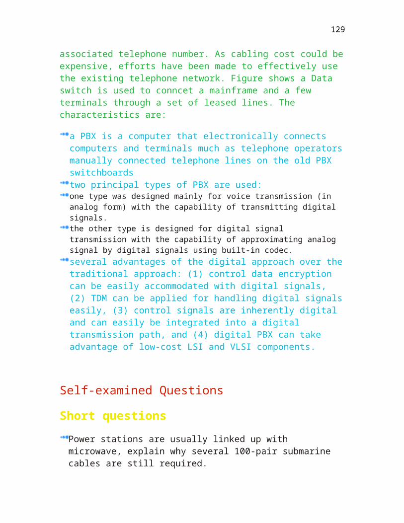
Type Description
Even Parity The total number of binary ‘1’ bits for a particular character is even. For example
Odd Parity The total number of binary ‘1’ bits for a particular character is odd. For example
An ASC character transmitting at asynchronous mode will have:
1 start bit + 7 data bits + 1 parity bit + 1 or 2 stop bits = 10 bits, not just 8 bits
The advantages and disadvantages are:
Advantages Disadvantages
Can you explain why overhead is 10%?
Parity Bit/Total Bits
Longitudinal Redundancy Check
This method is better than a simple Vertical Redundancy Check. The data is grouped into blocks of characters, say for example 12 bytes from the Hong Kong Stock Exchange, each of the character has a parity bit added. A block check character (BCC) is then appended to the end of each transmission block. The size of BCC can be 8, 12 or 16 bits depending on the algorithm.
The parity bits at the end of each character are known as Vertical Redundancy Check (VRC) while the BCC is called the Block Check Character (BCC).
The advantage and disadvantage is:
129
Advantage Disadvantage
Improved error detection capability More overhead is required in coding/decoding and transmission of LRC
Both parity and two-coordinate parity checking are commonly used in low speed communication.
Bits in characters
1 2 3 ... n LRC
Cyclic Redundancy Check
This is a faster method and is commonly used in protocol operating at synchronous mode such as SDLC. In this method, the data to be sent is divided by a set of binary constant called the generator polynomial. The remainder after division called Frame Check Sequence (FCS) will be appended to the original data stream. The original data plus the frame check sequence will be transmitted over the transmission media. At the receiving end, the received data will be verified by using the same generator polynomial to determine whether the message received is error-free. CRC can be implemented by means of hardware such as Synchronous Communication Chip (SCC) chip which provides the necessary circuit in physical layer to detect the transmission error.
The generator polynomial defined by CCITT for use on the switched telephone is:
X16 + X12 + X5 + X0
The equivalent binary expression is 10001000000100001
Another commonly used code is the CRC-16:
130
X16 + X12 + X2 + X0
Write down the binary expression.
These 16 bit codes can detect the following errors:
All single bit errors All two bit errors All errors with an odd number of error bits All burst error of length 16 bits or less 99.97% of 17 bit errors
Error is measured in terms of Bit Error Rate. Typical value for switched line is 10-5.
What is the FCS if the frame transmitted in decimal is 728 and the generator polynomial is 13? Assume two digits are used for error checking.
Byte and Bit protocols
The data link layer protocols based on the frame structure (whether frames are constructed out of bits or characters) can be classified into:
Byte oriented such as IBM BSC Bit oriented such as HDLC (High level Data Link Procedure) or SDLC
The control information in a frame does not need to be continuous. Typically, the delimiter field and the error checking field are separated from other control fields.
Can you list the dummy character used by SNA/SDLC, when there is no data being transmitted?
It will send out a string of flags
The frame format for Byte oriented frame is:
131
SYN SYN DLE STX Data DLE ETX BCC BCC
And the Bit oriented frame:
Flag Address Control Data........ FCS FCS Flag
What is the advantage of bit oriented frame compared to byte oriented frame in terms of data position identification?
The protocol can detect the exact location of control and data filed without processing the individual characters.
Byte-oriented Protocols
This type of protocols was developed a long time ago. A well known example is the IBM BISYNC protocol used in Remote Job Entry (RJE). The computer has to stripe down the character by character within the frame in order to determine the meaning and action of received data.
The Byte oriented protocols such as BISYNC have the following characteristics:
Half duplex in Data Link Level ( can have FDX or HDX in physical level.) Data link Level (not in physical level) An industry standard Used in Synchronous modem (Some users may use Sync/Async protocol converter to fit into his own system such as Reuters.) Uses either ASCII or EBCDIC as the code sets Ideal for Low speed and High volume transaction Uses VRC, CRC or LRC to determine transmission error
BISYNC is widely used in:
Remote Batch Interactive terminals CPU to CPU communications such as Prime to IBM. (Getting unpopular)
132
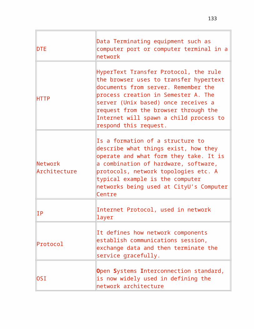
A typical BSC format delineated by a pair of PADs is:
PAD SYNC
SYNC
SYNC
SYNC
SOH HEADER
STX TEXT
ETB BCC BCC PAD
Type Description
PAD Used to indicate the block start
SYNC Used to synchronize the receiver
STX Used to indicate the Start of Text
ETX Used to indicate the end of text
SOH Used to indicate the start of header
BCC Block Check Character for error checking
ETB Used to indicate the end of message block
ACK Positive acknowledgment
NAK Negative acknowledgment
WACK Wait for acknowledgment
ENQ Enquiry message
TTD Temporary Text delay
Byte stuffing
133
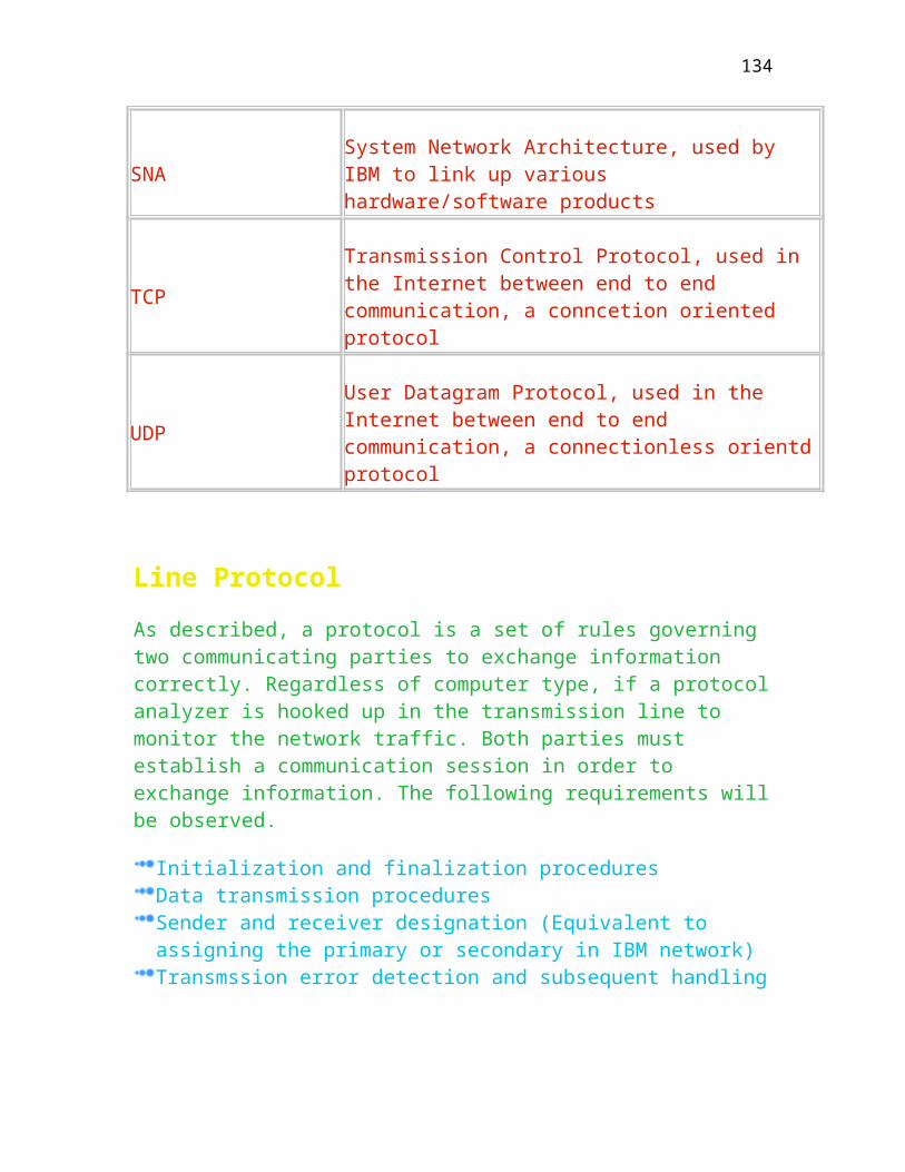
Since BISYNC uses a lot of binary characters (STX, SYNC) for control purpose, a pair of special characters DLE is used to quote the binary data so that the receiver will transparently treat the bracket data. Use of DLE to quote data is called byte stuffing as given below:
STX TEXT EXT TEXT ETB TEXT ETX BCC BCC
DLE STX TEXT ETX TEXT DLE ITB
BSC Line States
There are FOUR line states that BSC will be used to transfer data. Initially, BSC will be in disconnected state until it receives an event, it will then change to other state and take appropriate action.
Type Description
Disconnected No virtual connection has been established
Connected A virtual connection has been established. The line can then move to Text or Control state.
Control Can exchange control information such as ENQ or ACK0 etc.
Text Data frame is exchanged.
Data Flow
The principal means of flow control is to lay down rules to control if a sender can transmit a frame. For simplicity, both send and receive party can be considered to consist of a sender and a receiver as shown in Figure
134

BSC uses simple stop-and-wait protocol. The sender, after sending a frame, will stop and wait for an acknowledgment frame (from the receiver of the peer party) before sending another frame. The data link layer frames of such a protocol may consist of an information and acknowledge frame as shown in Figure .
The general frame flow diagram is given in Figure
Normal BSC Data Flow (BSC Contention)
Figure shows the normal data flow with acknowledgment frame. The transmitter initially transmits an ENQ and waits for an ACK0 prior to sending the test frame.
The receiver uses ACK0 and ACK1 alternatively to inform the transmitter that the messages are received correctly. Can you explain the reason behind?
Line Bid Time outs (BSC Contention)
After polling the remote for eight times, the sender may assume that the remote machine is dead (usually power off) and will stop polling. These retried time-outs can be configured by the user. Figure uses the two seconds as the time-out value.
Error Control - NAK (BSC Contention)
As shown in Figure , a NAK (negative acknowledgment) will be sent back to the transmitter, if the received data has detected a transmission error by checking the received frame against the Block Check Character (BCC).
Error Control - Lost Acknowledgment (BSC Contention)
135
If the transmitter cannot receive the acknowledgment from the receiver, it will send an ENQ instead of data frame and waits for the positive acknowledgment from the receiver as shown in Figure . Note that there is a 3-second delay for replying an ENQ.
Error Control - Lost Message (BSC Contention)
Similar to Figure , the transmitter will send an ENQ instead. However, the receiver will send an ACK0 instead of ACK1 after receiving the second ENQ.
Can you draw a distinction between Figure and ?
WAIT FOR ACK - WACK (BSC Contention)
If the receiver is busy, it will respond an WACK to temporarily stop the sender until the busy condition is removed. Once the condition is over, it will send an ACK0 to inform the sender to re-send data frame.
Temporary Text Delay - TTD (BSC Contention)
In this case, the sender is busy, it delays for 2 seconds and sends an TTD to inform the receiver to suspend the transmission as shown in Figure . The use of TTD is to maintain the communication link between the sender and receiver.
Duplicated frames
Duplicated frames occur for various reasons such as lost of acknowledgment. Figure shows the duplication of data frame due to lost frame and Figure shows the condition when the receiver is too late to acknowledge the frame.
Duplicated frames can be handled by the use of sequence numbe, can you explain why it can fix this number?
The user can check the correct sequence and remove duplicated frames by just looking at the sequence number.
136

Bit-oriented Protocols
These protocols interpret the message as a stream of unstructured bits and uses the relative bit position to determine the control information. This mechanism is more efficient compared to byte-oriented protocols and is extremely suitable for simultaneous communications protocols such as HDLC and SDLC. The entire message is delineated by a Flag whereas the BSC has to use numerous control fields such as SYNC, STX etc.
A typical bit oriented frame (HDLC) is given below:
Type Description
Flag This is the delimiter used to identify the start and end of variable-length frame. An example is 7EH in HDLC.
Address This is the destination address associated with the communications device in the network. This address is also called physical address.
Control Contains the type of information about the message itself. Control byte can be used to classify Supervisory, Unnumbered and Information frames.
Data Data portion of message. Data field is only available for information frame and is regarded as packet without frame header and trailer.
FCS Frame check sequence using CRC-CCITT or CRC-16 to ensure transmission error free.
Control field format
There are three different formats for this fields, with a few bits assigned to identify which format is being sent. Figure shows various control formats.
The three formats are:
137

Type Description
Information format (I) including a send sequence, a receive sequence and an information field.
Supervisory format including a receive sequence and two bits to indicate different supervisory format such as RR, RNR and REJ etc.
Non sequence format Having no sequence count and is used for setting operating mode. For example, the UA (unnumbered frame acknowledgment)
Bit stuffing
Bit-oriented protocols use a unique sequence of bits such as 7EH for the start and end of frame. To avoid an occurrence of this flag bit pattern (01111110) anywhere, the sending station will automatically insert an extra zero into the five contiguous ‘1’ bit stream. The receiving station will monitor the bit stream and delete the extra zero.
0111 1110 address Control Data 0111 1110
FCS FCS 0111 1110
Try to insert a zero bit for Five consecutive 1, as shown below:
0111 1110 address control data 011111010
FCS FCS 0111 1110
Primary & Secondary Stations
There are two types of stations defined in these protocols:
138

Primary Stations It is responsible for controlling data link by issuing commands such as Receive Ready. Secondary It receives commands from the primary and return responses.
In IBM SNA/SDLC, if the receiver does not receive any message for longer than 32 seconds, it will assume that the primary is not functioning and subsequently disable the line.
Figure shows the three operation modes. Here, Normal response mode support one primary and a few secondary stations, whereas asynchronous response mode and asynchronous balanced mode support only one primary and one secondary.
HDLC
The High-level data link control protocol (HDLC) is a full-duplex bit-oriented protocol. This protocol has a few configurations as given in Figure .
Type Description
Normal Response mode
Used in multipoint environment with Master/Slave relationship. The master is responsible for polling the slaves by periodically sending a special poll frame. In IBM SNA/SDLC, the polled frame is SNRM (Set Normal Response Mode).
Asynchronous Balance Mode
Used in point to point link where the stations behave as peers. This mode is used by X.25 to establish connection.
HDLC CONTROL FRAME FORMATS
139
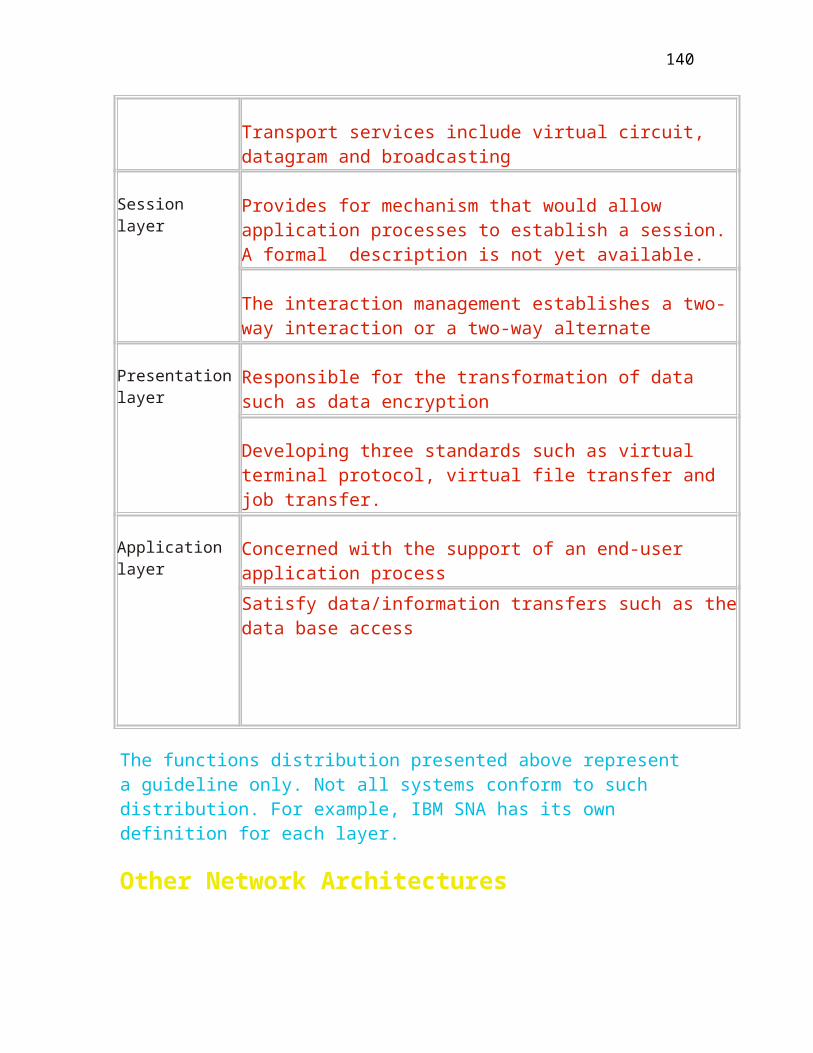
Below shows the comparison amongst all data link layers.
Name LAP LAP-B HDLC SDLC
Information I I I I
Receive Not Ready RNR RNR RNR RNR
Receive Ready RR RR RR RR
Reject REJ REJ REJ REJ
Selective Reject
SREJ
Set Normal Response Mode
SNRM SNRM
Set Asynchronous Response Mode
SARM
SARM
Set Asynchronous Balanced Mode
SABM SABM
Sey Initialization Mode
SIN SIN
Disconnect DISC DISC DISC DISC
Unnumbered Information
UI UI
Unnumbered Poll
UP UP
Reset
RESET
Exchange Identification
XID XID
Unnumbered UA UA UA UA
140
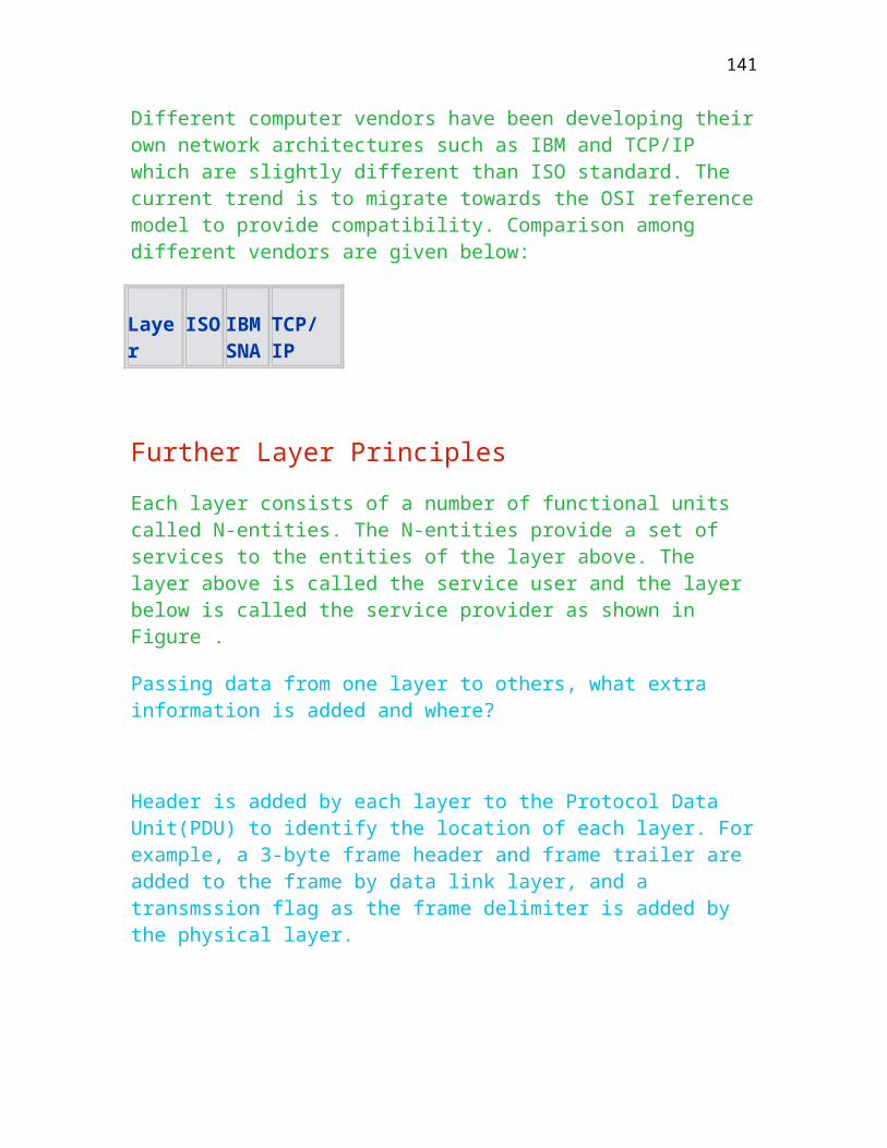
Acknowledgment
Disconnect Mode
DM DM DM
Request Initialization Mode
RIM RIM
Frame Reject
FRMR FRMR FRMR
Request Disconnect
RD RD
Command Reject CMDR
Test
Test
Beacon
BCN
Configure
CFGR
Based on above table, HDLC is a full specification comprising LAP, LAPB and SDLC.
Flow Control
There are two methods namely rate control and sliding window to regulate the flow of frames. Sliding window uses the size of sending window to restrict the number of frames being sent out.
Link Initialization & Disconnection Sliding Window (The normal value is 7 for 3-bit control field). It consists of Sending Window Receiving Window Error Handling (about the receipt of corrupted message(s)) Go Back N, ask the sender to repeat the whole sequence starting from the
141
first rejected message. (Some frames had been receivd by the receiver. As a result, it is less efficient.) Selective repeat, just to ask the sender to send the message(S) that was/were rejected by use of SREJ message. (It is more efficient. However, it needs buffer to store the previously received frames.)
Explain why selective reject is more efficient in full duplex data link and is the same in half duplex data link. The physical layer for both cases are full duplex in nature. That is to say, no need to check the voltage status of CTS.
UA is sent by the receiver to acknowledge the numbered frame during link initialization and termination.
Write down the full name of UA.
Link Initialization
Figure shows the methods of establishing a call under three response modes. UA frame is used to respond to all three cases.
Link Disconnection
Figure shows the methods of terminating a call under three response modes.
Explain why computer B will respond a DISC to machine A instead of UA for Asynchronous Response Mode.
Sliding Window Example
Figure shows two examples of using sliding send windows to control the number of frames to be delivered. In case 1, the transmitter can send out a series of frame numbered from 0 to 6 and in case, it sends out from 0 to 4.
Explain why it cannot send out the frames from 0 to 7.
No acknowledge will be used by the receiver to identify the number of frames received.
Data Flow
142
Figure shows the data flow by use of Information or Supervisory (Receive Ready) frames to acknowledge the sender. The use of information frames can speed up the response.
Error Handling
In case there is a transmission error, the receiver simply responds a Reject frame against the corrupted frame or a Receive Ready starting from the corrupted frame to the sender to re-send the whole frames.
In case various errors as listed below are not caused by transmission, the receiver will send a FRMR to the transmitter to reset the communication link. Software error could be one of the following:
Bad Address field Fewer than 32 bits between flags Information field is not a multiple of 8 bits
Receiver does nothing upon receipt of an invalid frame. It simply reports this event to higher layer and waits for a link re-initialization.
Explain why transmission error is not regarded as a serious error.
Go Back N, Error Handling
An REJ signal is sent to A for an invalid frame of sequence 5. Note that A has to re-send the data frame starting from sequence 5.
Selective Repeat, Error Handling
An SREJ frame is sent from B to A for an invalid frame of sequence 4 as shown in Figure $[F#,dc5-22]. Here, the transmitter can immediately send out the error frame without waiting for the last frame. This saves a lot of time to perform retransmission. Note that A only re-sends the corrupted frame of sequence 4. The performance is far better than the case in Figure .
143
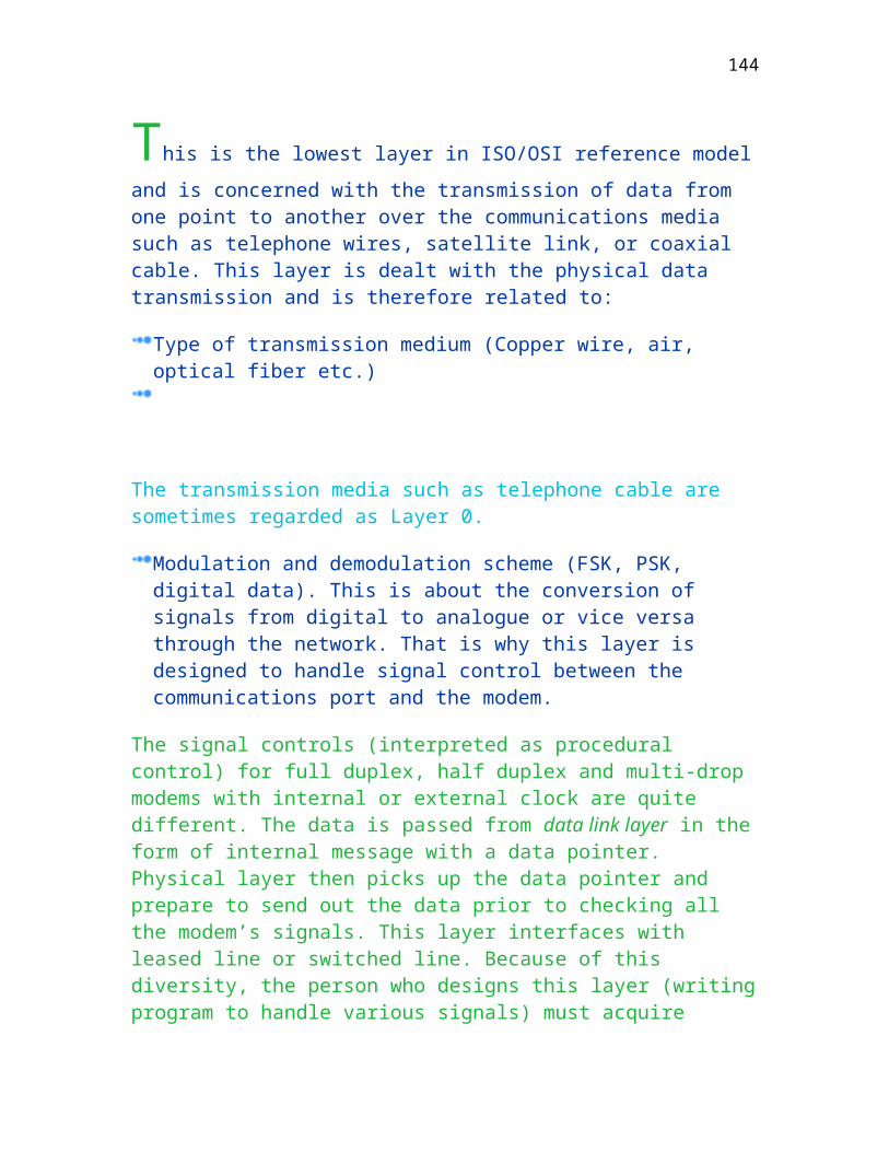
Self-examined Questions
HDLC
List the FOUR types of supervisory frames.
List the THREE modes defined by HDLC.
What is the function of the P-bit?
When is a FRMR sent instead of a REJ?
What is a problem of having a large window size?
What is the function of a sending window?
BSC
How are frames delineated in BSC? (What character, PAD, STX, ETX...)
144

How to fix the problem of duplicated frames?
What is the function of the EOT character?
True or False
UA is sent in response to SNRM.
RNR is used to respond to RR.
Information frame must be responded by Information frame .
REJ is sent against all the invalid frames for physical layer operating at half duplex mode.
145

Chapter Eight
Network Control and Monitoring
This chapter covers the third layer of ISO/OSI reference model. Network
layer is primarily responsible for routing the packets amongst the network nodes and avoiding network congestion. Upon completion of this module, you should understand:
Different switching techniques
The functions of network layer
Different routing techniques
Different congestion controls
The purpose of Network Layer is to provide data transfer from the source to
the destination across various communications media/sub-networks. It has to deal with issues relating to routing, addressing, congestion and flow control.
Switching Techniques
There are FOUR types of switching techniques available:
Circuit Switching (Telephone network) Message Switching (Telex network) Packet Switching (X.25 network) Cell switching (ATM network)
Figure is the diagram showing different line speed for various equipment to communicate through a packet switching network. In this diagram, a terminal
146
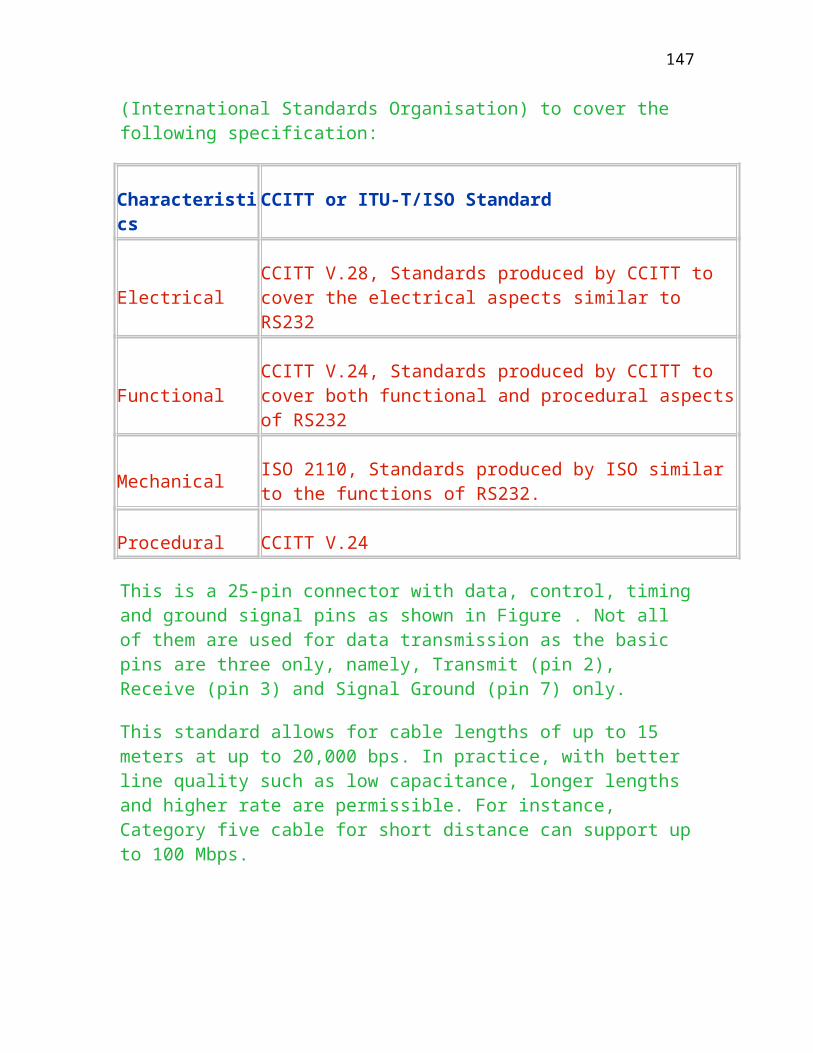
operating at different line speed can access the mainframe through the data network.
Circuit Switching
A dedicated path between the source node and the destination node is set up for the duration of communication session to transfer data. A typical example is the use of FAX machine in telephone network as shown in figure . The characteristics are:
Dedicated hardware connection between sender and receiver Real-time network response (limited delays due to equipment and signal propagation) Good For Burst traffic (such as telephone conversation) Relatively large set-up time Charging is usually based on distance/connect time
Can you figure out how long it takes to set up a FAX connection?
Longer than setting up a telephone call.
Message Switching
The user message is forwarded across the network one hop at a time. The entire message is transmitted and stored as a whole at each node awaiting for the routing decision to be made. This switching is sometimes called store-and-forward. A similar example is to program the electronic mail to send to different location at different time as shown in figure . The Characteristics are:
Greater line efficiency as each inter-nodal like can be shared by many messages from different users. Non-blocking, unless circuit switching a connection must be established prior to delivering data. Caters for different line speed.
147

Delay is relatively high.
What is the full name of IMP?
Why message switching is less efficient than packet switching?
Packet switching
The user messages are split up into packets of a fixed maximum size to be sent across the network as shown in figure . The whole user messages are reassembled at the destination node. Packet switching is efficient than message switching as pipelining effect can be achieved. This can significantly reduce the transmission time between the sender and receiver. The characteristics are:
Share communications channels within the network Flexible routing (can use the same physical channel to deliver messages to two different nodes within the network.) Limited block size (usually 512 bytes or 1 kbytes) Can be used for interactive access (Response time dependent on network usage) Charging is related to data volume
DATAPAK owned by Hong Kong Telecom is a packet switching network using SL-10 manufactured by Northern Telecom.
Cell Switching
Figure is the diagram showing the use of ATM switches to support multi-media traffic. These include voice, video, data etc. ATM network uses a cell of 53 bytes divided into 5-byte header and 48-byte payload field. The header contains the information regarding the destination node and error checking and handling while the payload field contains the data. The cell size of header is shown in Figure . Here, it has VPI and VCI both of which refers to the virtual channel identifier and virtual path identifier. Note that ATM network is ideal for optical fibre operating speed up to 8G bps, it is more efficient to divide into a number of physical paths and each path supports different channels.
ATM Layer
148
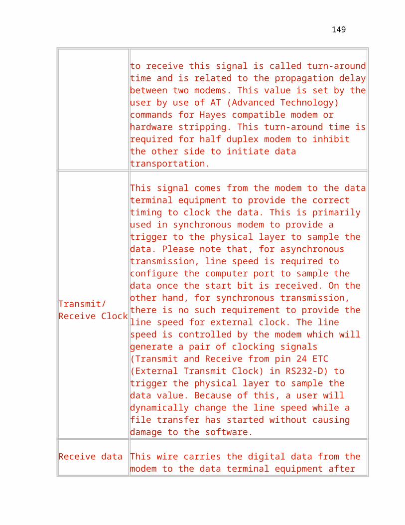
The ATM layer provides for the transparent transfer of fixed size ATM layer Service Data Units (53 bytes) between the physical layer and the adaptation layer. Currently, different headers are added to the data cell between the user and the network and between nodes. The header field for the network and network interface (NNI) and user network interface (UNI) comprises the fields of Generic Flow Control, Virtual Path Identifier, Virtual Channel Identifier, Header Error Control and Cell Loss Priority (CLP). Figure shows the position of ATM cell layer.
The cell header error control (HEC) is designed using polynomial convolution to check against multiple transmission errors and will correct a single bit error in the header field. The header error protection scheme in this layer was accepted by the IEEE 802.6 subcommittee and T1S1 in 1989. There is, however, no error checking on cell contents at this layer and no error protection or flow control from an ATM terminal onto the network. As the header’s virtual path identifier and virtual channel identifier are modified by the network at each hop, the header must be recomputed and checked by each ATM node to ensure no transmission error.
Virtual Circuits and Datagrams
The switching techniques mentioned previously are related to the properties of sub-communication network. From the network layer points of view, it has to make sure the packets received are in correct order. There are a lot of models existed to help address this problem, among them, two conceptual models namely virtual circuit and datagram dominate.
Virtual Circuits
In this model in figure , the network layer provides the transport layer with a perfect channel and all packets delivered in order. A virtual path or circuit is set up so that packets can pass through over this connection. This connection can be a permanent virtual circuit or switched virtual circuit analog to leased or switched line. The characteristics are:
Easier for the user host to use as the data is already in correct sequence. Circuit setup and disconnection is required each time. Sophisticated user may want to do their own error and flow control schemes.
149

Datagram
In this type of service as shown in figure , each message in the network is not related to any other messages. There is no connection between the sender and receiver. Also the transport layer of the receiver must handle error and flow control on its own. As there is no dedicated path between the sender and receiver, the subnetwork accepts packets (often called datagrams) which contain sufficient addressing information so that the packets can be individually routed within he network. Basically, the user supplies the packets and the subnet transports them to the destination.
The packets are routed individually and there are usually no delivery assurance between the sender and receiver.
The characteristics of datagram service are given below:
Datagrams are individually routed within the subnet No delivery assurance relating to the packets as the packets can be lost, out-of-sequence, contaminated, duplicated etc. Transaction (Sending a short message), connectionless oriented (No need to establish call prior to sending data.)
X.25 uses virtual circuit approach while TCP/IP Internet Protocol uses datagram.
Comparison between Virtual circuit and Datagram
Below is a summary about the Pros and Cons for the Virtual circuit and Datagram
Virtual Circuit Datagram
Host to host address is needed in link setup only
Host to host address is always needed in sending the datagram (Embedded in the datagram itself)
150

Errors is handled by subnetwork. Host will receive the packets in correct sequence.
Error checking is required by host to resemble the packet and find out the missing packets.
Messages passed in order to the network. messages may be out of order in the communication sub-network
Connection setup is initially required prior to sending data
Connection setup is not required
Network component failure in path may affect the result
Is a flexible foundation to support a range of higher level protocols which can provide for additional network services
Less overhead in addressing embedded in the packet
Overhead in addressing
Example is X.25 Level 3 Example is Internet Protocol of (TCP/IP)
Can you list a few more discrepancies in terms of packet processing, error handling, end-to-end flow control or efficiency?
Example of IP Protocol
TCP/IP is the protocol used in the Internet. It consists of five layers and the network layer consists of four protocols. The commonly used protocol is Internet protocol (IP) which uses Datagram to transmit data. Apart from this, it has three more protocols for signalling and control purpose as follows:
Internet Control Message protocol (ICMP)
Routing Information Protocol (RIP)
Address Resolution Protocol (ARP)
151
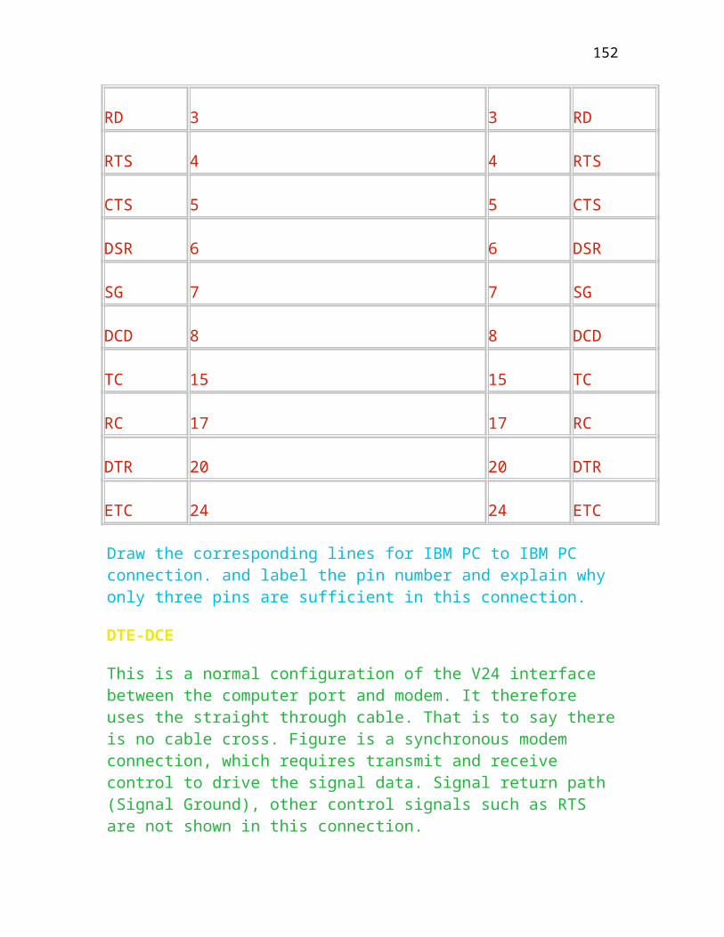
Internet Control Message Protocol(ICMP)
It is designed to pass control messages between gateways, routers and destination machines. This machine can be sent out in any of the following situations:
Use command such as PING to check if another host (machine) is available When a packet cannot reach its destination When a router can direct a host to send traffic on a shorter route When a host request a time stamp to check the machine time In case the router does not have the buffering capacity to forward a packet
Routing Information Protocol (RIP)
It is used by gateways to exchange routing information between any two nodes.
Address Resolution Protocol (ARP)
It is used to collect and distribute the information for mapping tables and is used to find out the corresponding physical address of destination node for an IP address.
Internet protocol
It is the basic transport mechanism for routing IP packets through gateways, router etc. It uses connectionless approach and is responsible for sending the blocks of data from source machine to destination machine. It does not provide a reliable transmission as it does not require acknowledgement from the receiving machine. It provides checksum on the IP header not the data.
The decision to have the network layer provide an unreliable connectionless service evolved gradually from an earlier reliable connection-oriented service. By putting all the reliability mechanisms into the transport layer, it was possible to have reliable end-to-end (transport-to-transport) connections even when some of the underlying networks were not very dependable.
The IP protocol works as follows:
The transport layer takes messages and breaks them up into datagrams of up to 64K bytes each.
152

Each datagram is transmitted through the Internet, possibly being fragmented into smaller units depending on the network frame size as it goes.
When all the pieces finally get to the destination machine, they are reassembled by the gateway or transport layer to reform the original message based on the fields of IP identification and offset in the IP header as shown in Figure . The IP header has a 20-byte fixed part and a variable length as shown below:
32 bits
Version IHL Type of service
Total length
Identification DF MF Fragment offset
Time to live protocol Header Checksum
Source address
Destination address
Options
153

Chapter Nine
Transport Layer
This chapter is about the characteristics of transportation layer including OSI
TP4 (Transport Protocol Layer Four) and Transmission Control Protocol (TCP) to establish and disconnect end-to-end connection. Various protocol formats and network types are also included in this chapter. Upon completion of this chapter , you should understand
The function of transport layer to establish and disconnect connection, and deliver message
The standard format of transport layer
The functions of Transmission Control Protocol and Internet Protocol
Various protocols supported
Characteristics of Transport Layer
The function of transport layer is to provide a reliable end-to-end communications service. It also provides data transfer service for the user layers above and shield the upper layers from the details of underlying network. This may include message error control and flow control functions. Optionally, it may provide for other transport services such as multiplexing (of multiple transport connection to a single network connectivity), inverse multiplexing ( mapping a single transport connection to a multiple number of network connection, for performance purposes). Figure shows the relationship between the subnetwork and end hosts.
The transport layer is the first layer that always resides in the end DTE’s. Also note that the transport layer uses the services of the network layer and shields
154

the upper layers from the details of the network connections and types of network used.
OSI transport protocol
To deal with different types of data transfer and different network services, International Standards Organisation (ISO) has defined 5 classes of transport services with naming convention from class 0, 1, 2, 3 and 4 in 1984. The choice of class is determined by the service desired:
the quality of service and functionality the underlying network service available.
The ISO/OSI TP (Transport Protocol) standard defines three types of network services to be used with various TP classes as given below:
Type
Description
Type A
This type of network refers to the connection with both acceptable error rate and acceptable rate of signalled failures. Packet delivery assurance and sequencing are guaranteed. In this type of network, the transport layer needs not worry about the quality and mis-sequencing of packets from the underlying network. A network with virtual circuit services is a typical example.
Type B
This type of network refers to the connections with acceptable error rate but unacceptable rate of signaled errors. The transport layer for this type of network must provide capability to recover from signalled errors.
Type C
This type of network refers to the connections with unacceptable error rate. The transport layer must be capable to recover from signalled failures and also handle the mis-sequenced packets from the underlying network. Internet protocol of TCP/IP, datagram based networks and certain Local area networks are typical example of this type of network services.
155

Due to different nature of network services, transport layer must be configured to specify the quality of service (QOS) with appropriate classes of protocol. In Transport Layer 4, there are five classes of protocol procedure from class 0 to 5 to incorporate the quality of service of underlying network. The table below shows the description of classes of protocol together with associated underlying network types:
Class Network connection type
Basic functions required of class
0 A Simple class with set up/ close connection. If there is an error with the underlying network, the transport layer simply releases the connection and inform the status to upper layer.
1 B Basic failure recovery. This class allows the transport layer to retain and re-synchronize the numbered data. It is also capable to perform re-connection in the event of network failure.
2 A Multiplexing. This class is an enhancement to class 0 to support the multiplexing of several transport connections into a single network service. It also supports message flow control to avoid congestion, but does not support the recovery from signalled failures. That is why this type of class must work with type A network.
3 B Failure recovery and multiplexing. This class is an enhancement of class 2 to support the recovery from network failure. In this class, the data will be buffered in the sender to allow for data re-transmission.
4 C Error detection and recovery. This class is an extension of class 2 and 3 to support the flow control functions. That is why this class is designed to work with type C network.
Explain why class 0 cannot work with type B or C network.
156
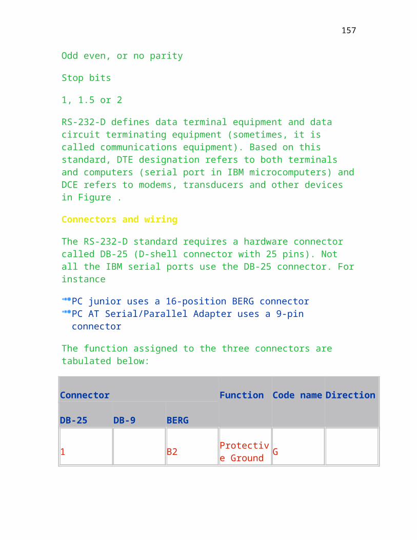
Type C or B network is an unreliable network and may occasionally cause signalled failure to the transport layer to frequently stop the connection.
Transport Services
The transport services are broadly classified into connection management and data transfer as shown in figure . The data transfer is further classified into normal data transfer and urgent data transfer (Expedited). The expedited data is equivalent to sending control characters to abort a remote program. Error detection and handling are also supported by means of message checksum and message sequencing.
Connection establishment
To establish a connection, the part A as shown in figure will send out a standard message , T_CONNECT_REQUEST to Part B through the underlying network. These types of message are specified by ISO to include the address of calling and called side (Party A and Part B in figure and quality of service as described above. The called side (Party B) will process the received message and may respond to the calling side with an acceptance or reject message depending on the current state of called side and the correctness of message received. Once calling side receives the CONFIRM message it will process this request by sending a reply to upper layer. The transport service primitives to establish a connection is based on ISO 1984a, table 3, section 2.
Primitive Parameters
T_CONNECT.request Called address, calling address, Expedited data option, Quality of services, TS user data
T_CONNECT.indication Called address, calling address, Expedited data option, Quality of services, TS user data
T_CONNECT.response Quality of service, Responding Address, Expedited Data option, TS User data
T_CONNECT.confirm Quality of service, Responding address, Expedited Data option, TS User Data
157

Additional explanation is as follows:
Term Description
Expedited data Option
Indication as to whether the option is requested (.Request) or will be made available (.Confirm)
Quality of service User’s requirements for throughput (Octets/Sec), transit delay, reliability, and priority of the connection
TS User Data Up to 32 Octets of user data that can be appended in the connection message.
Data transfer
Figure shows the data transfer between two parties using T_DATA_REQUEST. There is no acknowledgement by the receiving transport user. The transport layer protocol is responsible for current delivery. TSDU’s (Transport Service Data Units) are always delivered in sequence to the receiving transport user. Also, the transport layer may segment a TSDU into multiple transport protocol data units (TPDU).
Primitive Parameters
T_DATA.request Transport service user data
T_DATA.indication Transport Service User data
T_EXPEDITED_DATA.request Transport service user data
T_EXPEDITED_DATA.indication Transport service user data
T_UNIT_DATA.request Called address, calling address, Quality of service, security parameters, TS user data
T_UNIT_DATA.indication Called address, calling address, quality of service,
158

security parameters, TS user data
T_UNIT_DATA.confirm Result, Reason
Expedited data (Max 16 octets of user data) bypasses normal data end-to-end flow control. The transport layer ensures that expedited data will not be delivered to the receiving transport user later than any normal data sent after it.
ISO connectionless data service does not include confirmation. It is up to the service user to handle retransmission where necessary. Below is a state transition diagram for possible allowed sequence of TS primitives at a transport connection.
Connection termination
There are two procedures of terminating a connection by Exchange of TPDU’s successful connection, class-2 transport protocol and Exchange of TPDUs, successful connection, class-4 transport protocol. For the former case, the called party simply responds the DISCONNECTION_CONFIRM message to terminate the call as shown in figure .
Protocol Operation
As in other layers, primitives across the layer boundaries would invoke exchange of pdu between the peer (transport) layer and vice versa. In the following class 4 transport protocol (over type C network connection) and class 2 transport protocol (over type A network connection) are described.
Below is a table for transport protocol data units with appropriate code to identify the message format.
TPDU Type Code Amount of data carried
CR, connection request 1110 = 32 octets
CC,,connection confirm 1101 = 32 octets
159
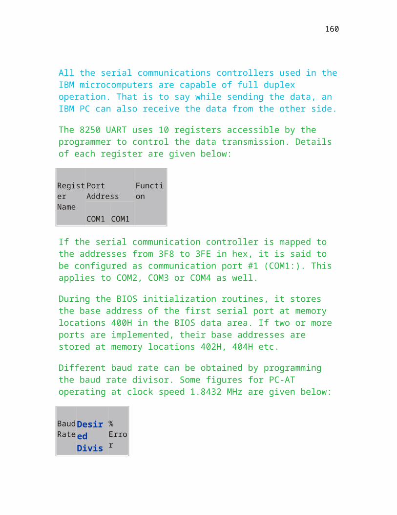
DR,,disconnect request 1000 = 64 octets
DC,,disconnect confirm 1100 none
GR,,graceful close request* 0011 none
ERR,,TPDU error 0111 none
DT,,data 1111 up to negotiated length
ED,,expedited data** 0001 16 octets
AK,,acknowledgement 0110 none
EA,,expedited data acknowledgement**
0010 none
UD,,unit data 0100 up to maximum value of network service data data unit (NSDU)
Example of TCP protocol
The TCP/IP (Transmission Control Protocol/Internet Protocol) is a de facto commercial standard designed to solve above-mentioned communications problems. It combines the connectionless layer 3 protocol (IP) and the transport layer 4 protocol resembling class 4 of X.224 (ISO 8073). TCP/IP has been widely used on the ARPANET and is now a commonly used commercial product.
Figure depicts the four conceptual layers that build on a hardware. The application layer is the highest layer to allow users to invoke application programs that access services available across a TCP/IP internet. The duty of transport layer (TCP) is to provide end-to-end communication from one application program to another using port number. It is connection oriented protocol and regulates the flow of information and provide reliable message
160

transportation in sequence. The duty of internet (IP) is to handle communication from one machine to another. It accepts a request to send a packet from the transport layer with an identification of the machine. TCP/IP has been widely tested as a robust product with error recovery and can tolerate error rates including duplication, damage and lost messages. A typical example of The TCP/IP protocols and functions grouped by their layers from network up to application is:
Application Telnet FTP TFTP SMTP DNS LPR RouteD NFS/RPC REXEC POP2 TIME
Sockets
Transport TCP UDP
Network ARP RIP IP and ICMP
Data link/Phusical Token-ring, Ethernet V2, IEE 802.3, IBM PC network, Asynchronous
TCP/IP is a connection oriented end-to-end protocol that is ideal for a wide spectrum communications. One of the TCP/IP’s key benefits is that it provides a set of standard applications including File Transfer Protocol(FTP), Simple Mail Transfer Protocol (SMTP), Terminal emulation services (Telnet), and User Datagram Protocol (UDP). TCP/IP implementations are available for MS-DOS/Windows, Windows 95/98, Windows NT and OS/2 based personal computers, Unix based workstations, a range of minicomputers and mainframes running INM’s MVS. Below summaries the function groups that are supported by TCP/IP protocols.
Physical Layer/Data Link layer
TCP/IP can support a few configurations including:
Token Ring Ethernet V2 IEE 802.3 IBM PC Network Serial Line such as City Link Plus through COM1 or COM.
Transport protocols
161
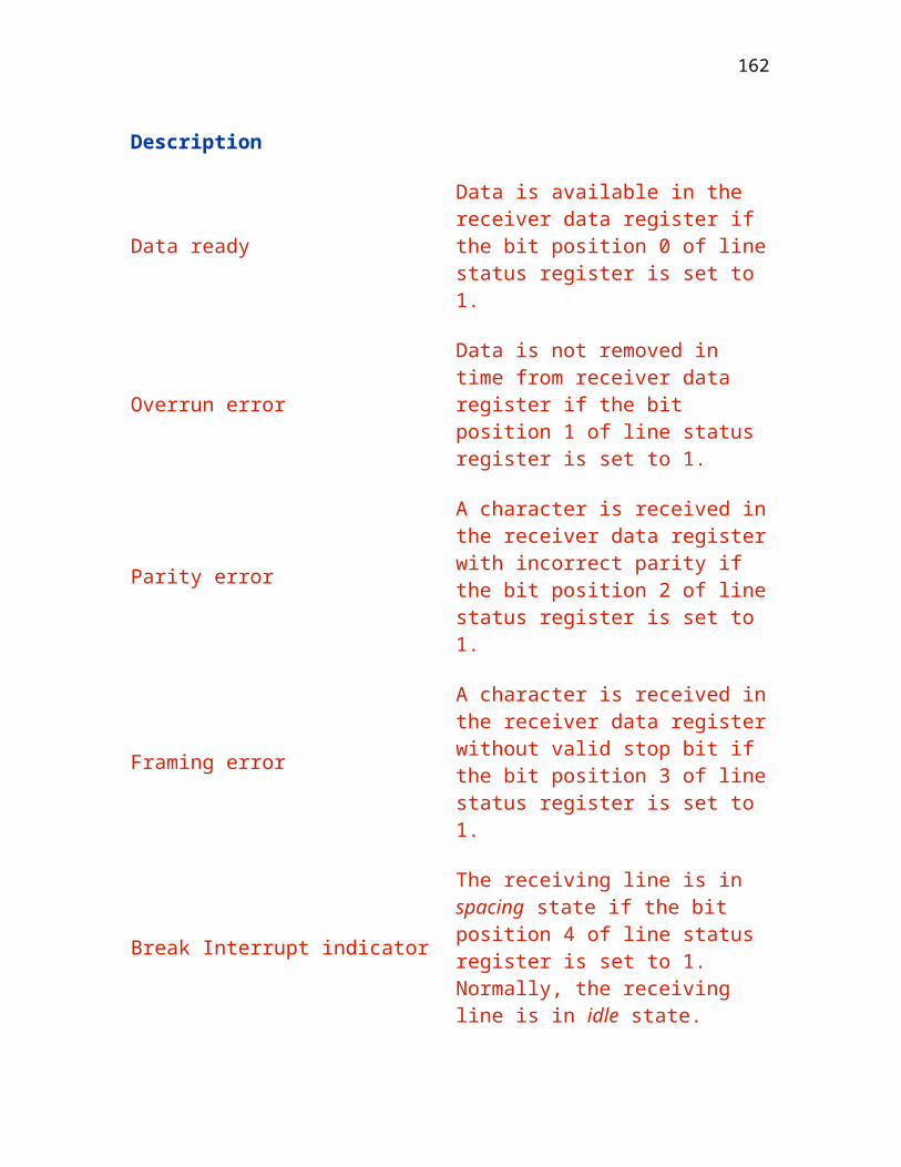
It consists of two protocols namely:
Transmission Control protocol (TCP) (Connection-oriented)
User datagram protocol (UDP) (Connectionless-oriented)
User datagram protocol (UDP)
It provides an unreliable mode of communication between source and destination with a minimum of protocol overhead
TCP
It provides a reliable communication method for delivering packets between machines through a network.
Original versions of TCP layer 3 were expected to offer connection oriented transmission. but as the APARNET grew and included packet radio subnets, satellite channels etc., the end-to-end reliability decreased and this forced a change to tolerate unreliable subnets. Based on ISO 8073/X.224).
A TCP transport entity accepts arbitrarily long messages from user processes, breaks them up into pieces not exceeding 64K byes, and sends each piece as a separate datagram. the network layer gives no guarantee that datagrams will be delivered properly, so it is up to TCP to time out and re-transmit them as needed. Datagrams that do arrive may well do so in the wrong order; it is also up to reassemble them into messages in the proper sequence.
Every byte of data transmitted by TCP has its own private sequence number which is 32 bits wide to make sure that old duplicates have long since vanished by the time the sequence numbers have wrapped around. The header format is:
Bit Position
1
32
Source port Destination Port
162

Sequence Number
Piggyback acknowledgement number
TCP header length
URG ACK EOM RST SYN FIN
Window
Checksum Urgent pointer
Options
User data.............
163
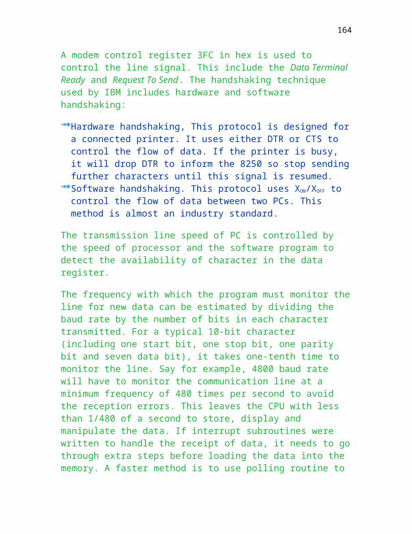
Chapter Ten
X.25 and Network Management
This chapter is about the Wide Area Network using X.25 packet switching.
The functions and characteristics together with the networking components and network management are also included. Upon completion of this chapter, you should understand
The X.25 network
The network management in various networks
Modem diagnosis
Network design
X.25
With the increase in computer communications, there is a
strong need for a data communication subnetwork that would offer better services and prevent the problem of incompatible interfaces. In 1976, CCITT first published a series of standards namely X.25 for international standard network access protocols. X25 only:
Defines three layers only not the whole seven layers including: Physical layer Data link layer Network layer Does not define internal subnet protocols.
164
Figure depicts the X.25 (DTE to DCE) interface and link connection through Data Switching Exchange.
X.25 Level 1
This definition is consistent with OSI layer 1 and is classified into two categories (Analog and digital) depending on the network type to be connected.
X.21 bis Interface to analog network Equivalent to RS-232C - V.24. Referring to Figure . X.21 Interface to digital network (may also support X.21 bis/ RS232C to those which does not support). Deatils of connection, pleas refer to Figure . Limited Support in Hong Kong
X.25 Level 2
This is consistent with OSI layer 2. The function of this level is to ensure reliable communication between DTE and DCE as shown in Figure . The protocols used include:
LAP (SARM) (Set Asynchronous Response Mode) LAP-B (SABM) (Set Asynchronous Balance Mode)
Figure shows the comparsion between the OSI and X.25 protocol structure. Note that above layer 3 in X.25 is not defined.
X.25 uses virtual circuit approach and is only responsible for delivering the packets from source to destination in a reliable manner. There, X.25 does not conform exactly to OSI reference model, only the lowest three layers. The main difference is in the interpretation of the services provided by the network.
X.25 Level 3
165

This is similar to OSI layer 3 and is called the X.25 Packet Level Protocol (PLP). It provides:
Virtual circuits. (With permanent virtual circuits and switched virtual circuits analog to leased and switched lines in PSTN.) Datagram (Sending individual connectionless oriented packets through different communication paths) PAD support
Virtual Circuit Operation
The X.25 operation involves three steps by delivering and accepting appropriate packets between end-to-end node in order to exchange information :-
Establish virtual circuit Call request by sending a Call Request packet Call accepted by responding a Call Accepted packet Data exchange once the connection has been established. To terminate the connection is To send a Clear Request packet Wait for the confirmed by receiving a Clear Confirmation packet Time-out is used to establish limits on how long it takes to get connections.
Figure shows the procedures of exchanging data packets.
Packet assembler-disassembler
The X.25 as specified can only communicate with terminals or computers that are intelligent using synchronous transmission mode (LAP or LAPB). However, a lot of terminals such as teleprinter are dummy terminals. CCITT therefore specified a particular protocol converter that can support terminals of :
Asynchronous type (Using start/stop transmission mode) Character mode rather than block mode (Sending or receiving character by character) Dial up or leased line between the terminal and the network boundary (DCE)
166
CCITT made a number of recommendations that specify the (Packet assembler-disassembler) PAD and the X.25 network:
X.3 - this defines the PAD parameters. For examples, parameter 3 = 0 is used to instruct the PAD to forward only a full packet and parameter 3 = 2 is used to instruct the PAD to forward a packet upon the terminal sending a carriage return character. X.28 - this defines the interface between the terminal and the PAD. Upon receipt of an initial connection for the user DTE, the PAD establishes a connection and provides services according to X.28. X.29 - this defines the host (DTE)-PAD interface. This standard provides direction for the PAD and a remote station to exchange control information in an X.25 call.
PAD provides protocol conversion from asynchronous to synchronous transmission mode and vice versa for a user device to a public or private data network. The interface between the PAD and network is X.25. (from level 1 to level 3)
Figure shows the terminal connection to the network through a PAD.
List the difference between X.28 and V.24.
Basically the same except that X.28 is for digital network such as X.25 and V.24 is for analog network such as PSTN.
X.25 packet header
Figure shows the relationship between a frame and a packet with appropriate labelling for virtual channels and paths. A packet header as shown in Figure is used by public data network at network level to perform end-to-end routing.
167

The description for each field is attached for reference only. The details should be covered in a later course entitled “Wide Area Networking” in Year 3.
Type Description
General Format Identification
It indicates the general format of this packet. The first bit of General Format Identification (GFI) refers to the sequence number modules (Modulo 8 or 128). The second bit of GFI indicates whether the packet is a data packet (bit 0 ) or supervisory/reset packets (Ready to Receive (RR), Not Ready to Receive Packet (RNR)
Logical Channel Group Number (LCGN)
This together with logical channel number (LCN) provides a two level hierarchy only. This identifier (LCGN + LCN) is used in almost every packet type to identify the connection. The assignment of channel number depends on the type of service. For example, number is assigned per-call basis during call establishment for switched virtual circuits and is fixed for permanent virtual circuits. With 12-bit different channels, the total number can be up to 4096 different logical addresses to be used in the network. Using the concept of channel number, a data link level frame can support 4096 logical channels or CPU processe.
Packet Type
This one byte information refers to one of six categories packet type including Call setup and Clearing, Datagram, Data and Interrupt, Flow control and Reset, Restart, and finally Diagnostic. Certain packet types may be further sub-divided into incoming call or call connected. For example, the value for Interrupt packet format in binary is 0 0 1 0 0 0 1 1.
Calling DTE address length
It indicates the lengths of the calling DTE address. The format is Binary Coded Decimal (BCD) digits.
Called DTE address Length
Same as calling DTE address length, it refers to the address length of called DTE address.
DTE (called/calling) The format is specified by X.121. The first four digits are
168

addresses
the Data Network Identification Code (DNIC) followed by up to ten National addresses (eight digits Network Terminal Number plus two digits sub-address corresponding to different processes within the DTE). Regarding the DNIC, the first three digits identify the country assigned by International Telecommunications Union (ITU) and the fourth digit identifies the network within the country.
X.25 protocol
It makes use of the concept of logical channel. A logical channel is a conceptual path between a DTE and the network. Multiple logical channels are multiplexed on an X.25 interface between the DTE and the network. Each logical channel, when active, supports an active virtual circuit as given in Figure .
Logical channel numbers for Virtual circuits are assigned at call set up time.
The services offered by X.25 include:
Switched virtual circuits (SVC) (Analog to public switched telephone service) Permanent virtual circuits (PVC) (The connection is automatically established once the device connecting to X.25 network is booted up.) Datagrams(Equivalent to connectionless service. Not explicit virtual path is set up prior to sending packets.)
X.25 Application Example
Figure is an example that makes use of X.25 to provide communication access by external users through a X.25 gateway. This gateway is connected to the LAN, which means that all the computing facilities connecting to the LAN can be accessed as well.
169
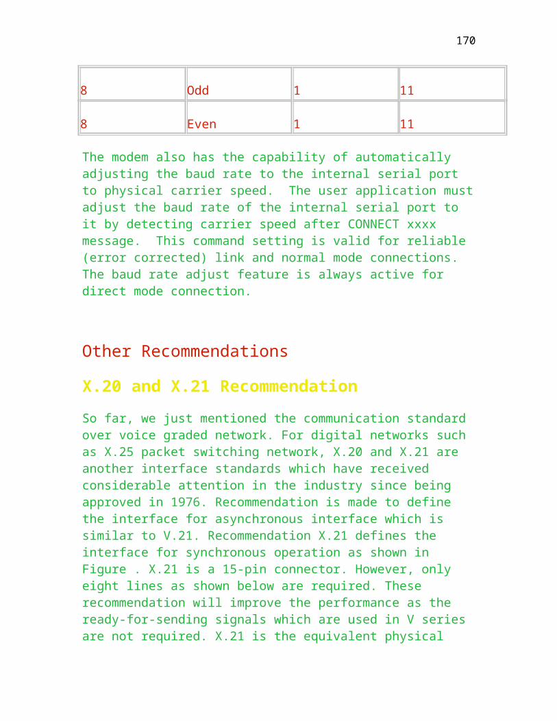
When you use the dial-in service to remotely log into CityU’s network, you already make use of X.25.
Network Management
Once a network has been established, it is a good idea if one can control it; monitor its performance; diagnose faults; reconfigure in the event of failure; etc. All of these involve network management. An efficient and reliable network depends on:
Type Description
People
There are not many on the market and requires on-the-job training. Usually, the problem for the systems designer (network engineer) is to estimate the likely incidence of faults for each component in the data communications systems (Mixed up with SNA/SDLC and non-SDLC network.) The problems facing the users is to recognize the type of fault he is experiencing and then to alert the appropriate support to restore the service.
Equipment This includes: testing equipment for diagnosing faults; reconfiguring equipment such as patching and switching facilities.
Software Among other things, the software can provide performance statistics to help sort out the bottleneck.
Measures of System Effectiveness
Three factors, namely, availability, reliability and cost-effectiveness are used to measure how well the system is performing. Cost-effectiveness is about the way of selecting product and will not be covered here. A system is effective if it can provide good performance, which means a predictable transaction response time. For example, the response time for an automatic teller machine
170

is less than 3 seconds after you have pressed any key strokes and wait for the response.
Availability
It means that all necessary components are operable and accessible. For a connection to CityU through the CityU Link Plus, it includes your PC, Windows 95, Browser, modem, telephone exchange, remote server etc. Accessibility means the user can make use of the component when needed. In the same configuration, assume that 300 channels are used. However, it is all occupied when you want to use it. Three more scientific factors to measure the performance are: Mean Time Between failures (MTBF), and Mean time to Repair (MTTR). For instance, a modem with MTBF of 1000 hours that operates an average of three days a day, 20 days a month, would be expected to fail once every 1000/(3 x 20 ) = 16 months. These figures are provided by the manufacturers to indicate the reliability of that product. MTTR is the average amount of time required to restore the failure into normal service such as replacing faculty modem using 30 minutes. Availability is defined as:
A(t) = a / (a + b) + b /( a + b) e-(a + b) t
where a = 1/MTTR, b = 1/MTBF and e is 2.7183
Given a modem having an MTBF of 2000 hours and an MTTR of 1 hour, the availability for an 8-hour period is
a/1 = 1 and b = 1/2000 = 0.005
A(8) = 1/(1 + 0.0005) + 0.0005e-(2 + 0.0005)8/(1 + 0.0005)
If multiple components are used in a communication link, the resultant link is simply the multiplication of all. For example, the availability of modem is 0.997, availability of line is 0.9 and the PC is 0.99, the overall availability is 0.997 x 0.9 x 0.99 =0.888. This means that in every 1000 tries, there will be 112 unavailability.
Reliability
It is concerned with the probability that the system will continue to function over a given operating period. It a transaction requires 1 second for a response to be received, then the reliability of the system is the probability that the system will not fail during that second. Reliability includes the error
171

characteristics of component such as modem, PC, Windows 95/98 and the transmission telephone line or cable. The the probability is determined by
R(t) = e-bt where b is 1/MTBF
If the MTBF for a modem is 1000 hours, and a transaction requires 1 minute, the reliability is R(1) = e-1/1000 =
Same as multiple components, the resultant reliability is the multiplication of all of them.
System components
For a typical IBM environment, faults are usually classified into four areas as shown below:
Display Terminal and operator IBM mainframe hardware Host Software Telecommunication lines and equipment
The problems originated from the hardware malfunction and inappropriate procedures can be summarized as:
Terminal operator procedure Terminal electro-mechanical malfunction Terminal logistics such as power disconnection, paper and fuses etc. Modem between Front end processor and Cluster Controller Telecommunication circuit Front-end processor ( 3725 ) Cluster controller ( 3174 or 3274 ) Computer center internal cabling Host communication software such as VTAM (Virtual Telecommunication Access Method) or VCAM (Virtual Communication Access Method), IBM proprietary products Host operating system such as TSO (Time Sharing Operating ) or Unix in HP Host processor hardware Application software Customer Interface software (CICS)
172
As shown in Figure for an IBM SNA network, which part is the role of a network engineer?
Circuit problem
Use of the telephone system for data transmission can cause problems for the user in a number of ways. The four main categories of problem include:
Line Errors
The transmitted signal becomes corrupted resulting in the addition or loss of bits. The line impairments are generally grouped into:
Type Cause
Steady state By random errors presented constantly
Attenuation loss or distortion
Background noise
Frequency shift - Sudden change of frequency change
Phase distortion
Non-linear distortion
Transient A lot of errors over a short period
Impulse noise - 6 db last less than 1 minisecond, all effects disappear within 4 miniseconds
Gain hits- Sudden changes of amplification
Dropouts - Sudden loss of amplitude
173

Phase hits - Sudden change in received signal phase/frequency
Transmission breaks
Three types of break can be identified each with different causes and requiring different protection as given below:
Short break - Temporary disturbance of connection such as engineering maintenance on the line. Long breaks ( last for a few hours ) - Serious disruption of service caused by accident to cable or plant Disconnection - removal or disconnection of cables
Contention
This is about the unavailability of service to the computer due to line engagement. There are two common causes of this problem:
All ports at the computer center are engaged The communications circuits are overloaded
Software consideration
Some level of fault detection is carried out by the software components as given below:
Line driver software in the host mainframe Telecommunications access software in the host mainframe Teleprocessing monitor resident in the mainframe whether supplied by the manufacturer. Intelligence available in network subsystem components such as front-end processor, concentrators and intelligent terminals. Special purpose diagnostic software, principally for use by field engineers.
The capability of software in terms of both the types of fault and the level at which they are detected, will depend on a number of factors such as:
174
Degree of intelligence in the network components to perform self-diagnostics The intelligence available to the monitoring equipment
Statistics collection
The principal reasons for collecting event statistics on a cumulative basis include:
To assess the overall performance of communication components and lines To review the effectiveness of fault diagnosis procedures To obtain prior warning of degrading performance before total failures
The detailed statistics logging and analysis should be decided by the network engineer based on the systems he is working on and actual operational experience.
Performance Statistics
Statistical information can be collected in the following IBM devices:-
Host (3090) Front End Processor (3725) Intelligent Terminal Control Unit (3174) External Equipment (3278/3279)
It is worthwhile to find out how many can be assembled in the system at regular intervals so that the network control people can see how the network is behaving. A lot of performance statistics are very useful such as:
Type Description
Character in/out This indicates the loading on the system and the traffic fluctuation during the day. It is helpful in keeping track of traffic growth.
Polls sent Is particular useful on networks using statistical multiplexers
175

Retries This indicates the number of messages that are re-transmitted. This statistic can be a useful diagnostic tool and can foreshadow a potential network component failure.
Time-outs Indicates how many polls or messages sent to terminals did not get a response. This statistic can indicate a faulty network component or can foreshadow a potential fault.
Response Times This is both a planning tool and a diagnostic aid.
Line utilization This gives an indication of the loading on a line. This is also a useful planning tool as well.
Can you fill in the following table to best project the performance of a system?
Statistic Network total
Per line
Per Terminal
Per application
Characters In/out
4 4 4
Messages in/out
Polls sent
Number of retires
Time-outs
Response time
176

Message in/out: Figure shows the volume of input/output messages for a certain time interval during office hours. The graph is normalized with respect to the maximum traffic experienced during that day over the specified interval.
Trouble Shooting
Goals of Datacomm Testing
The goals of datacommunication testing are to:
Increase system availability by Minimizing the network down time Expediting repairs by identifying precisely the faulty network components Eliminating finger pointing by randomly repairing functioning network components Debug network applications Develop good relationships with data communications vendors Isolate the failing component within the network
Testing domain
Analog testing Transmission impairment and continuity Measuring sets include voltmeter Digital Bit Error Rate Tester. It is used to measure the ratio between the error bits against the totally received bits including the error bit. Protocol Serial Data Analyzer (It captures the status of every V24 interface lead for every bit time on the interface. Data can be stored on tape or diskette for later analysis.) LAN Protocol Analyzer (To measure the network loading, performance and traffic pattern.)
Breakout box
177

Figure shows the use of break-put box to diagnose the network connection between a modem and terminal. A break-put box is
Visual verification of RS-232-C. This can be visualized by the flashing of LEDs(Light Emitting Diodes) corresponding to the data movement in the wire. Ability to alter signals by re-wiring the connection using either straps or DIP switches.
Protocol Analyzer
Figure shows the use of protocol analyzer to monitor the contents of data movement between a computer and a modem. The characteristics of protocol analyzer include:
Simulate and Monitor Modes Simulate mode is to configure the protocol analyzer to act as a DTE or DCE in the network usually used to perform software verification. Monitor mode is to configure the protocol analyzer to act as a monitor to keep check the data movement between a DTE and DCE. Softkey menu operation instead of using hard-code keys in the small console to configure the protocol analyzer Use BASIC language to program the analyzer to emulate DTE/DCE and capture special data stream. Softleds (means it can be programmed by the user. For instance, this lead is input RX, but be programmed as output TX) instead of physical leds
Modem diagnostics
As shown in Figure , by looping the analog side, the messages sent by DTE will be returned and processed by DTE to ensure that the analog and digital side of modem, and data link between two modems are working properly.
End-to-end Test
The text messages will be sent by one of the computers and be captured by another to verify the communication is in proper condition as shown in Figure . However, this procedure can only detect a single direction of data flow.
Remote Digital Loopback test
178

It uses a machine to perform loop-back text by looping the remote digital side (by twisting transmit and receive pins.) This can detect the send/return path as shown in Figure .
Designing a Data Transmission Network
The factors to be taken into account during the design of a data communication network should be the same irrespective of size. Small networks tend to grow in the future, careful design can ease the burden of growing pains. Fault isolation is accomplished by inserting testing points throughout the links at each network component.
The designer has to produce a network to connect terminals to the processing centers. These connections:
Must be within the capabilities of the protocols supported by terminal and host computer Must be fast enough to carry all the traffic at the required times Must be sufficiently reliable to meet the needs of users of the service.
Usually, there are four stages in identifying network requirements:
Defining the location of terminals including current and future needs. Determining the protocol to be used. It is used to determine whether a series of point to point links have to be used, whether terminals may be clustered or whether they may be connected in a multipoint arrangement. Defining the pattern of traffic which is likely to be transmitted. This will determine the speed at which the links have to operate. In the case of clustered and multi-dropped terminal systems, the traffic pattern will also determine how many terminals can operate on each link. Determining the reliability required for the network
Careful thinking is required to define the longest down time which may be tolerated, and how frequently interruptions are acceptable. A lot of factors must be taken such as:
The mean time between failures (MTBF) of most data communications
179

components Fallback arrangements including redundant components throughout the link, dial-up standby circuits
The types of terminal and the software under which they are to work, will determine some of the network options such as:
Synchronous or asynchronous? Contention or polled protocol? This will determine whether a point to point or multipoint structure is required. Does the software monitor and/or transmission control unit support dial-up links? Network or standalone?
Redundancy
Fallback arrangements for networks of private circuits usually take the form of standby facilities. There are three broad approaches to redundancy in the communications network as given below:
Duplication of those items of equipment which are likely to take longer to repair than the maximum permissible down time and keeping that equipment idle until it is required. Connection of the duplicated components into the link in such a way that they are normally being used. Then when they are required for fallback duty, they are known to be working. When more than one service is provided to a remote site the services should be ranked in order of priority.
Standby modem
As shown in Figure , a single standby modem is installed to replace the defective modem once a hardware problem is found.
Standby telecommunication lines
180

A duplicated telecommunication line is leased from Hong Kong Telecom using different route to replace the defective line once it is identified.
Standby Front end processor
A Front-end Processor is standby to replace the defective machine in case it is not working properly.
Self-examined Questions
Short Questions
What is bit error rate?
Which loopback test verifies the whole information channel?
What are some of the reasons for having networks?
What is the idea of local digital loopback?
What is the function of PAD?
What do the following standards define?
181

X.21__________________________________________________ V.24__________________________________________________ X.28__________________________________________________ What are some advantages of X.25 packet switching networks?
How to verify respective communication channels are working properly?
List the components required to design a reliable network.
List three redundancy methods and point out the cheapest method.
True or False
X.25 defines the first five layers of the ISO model.
X.28 defines the interface between the terminal and the PAD.
The data link layer of X.25 is HDLC only.
X.25 defines the internal subnet protocols to include datagrams.
182

Chapter Eleven
Signalling
This chapter is about signalling for various communication systems
including ISDN, LAN, leased line etc. There is no intention to cover the details of each of them as they will be covered in later courses. Upon completion of this chapter, you should understand
Format of T1, T2 and T3
Signalling method for LAN
The maximum signalling rate for ISDN, B-ISDN
T1 and its Highers
It is a carrier service, available from Hong Hong Telecom., and operates at the speed of 1.544 Mbps digital path. The T-1 carrier is divided into 24 separate channels each of them carries 64K bps digitised voice or 56K bps data (interesting they are not equal). T1 can be regarded as a high-speed method (10 or 20 years ago) of communicating digitally between two devices. The format for a typical T1 is shown in Figure . Data is transmitted in frames, each of (24 x 8) + 1 = 193 bits per frame. Within one second, it has to transmit 8000 frames over one second resulting in 8000 x 193 = 1544000 bits per second. The data rate for T1 is 1.54M bps. It is also concluded that 8000 frames per second include 8000x1 = 8K bps for synchronisation (last bit in the frame) and 24x64K = 1536K bps for data. If a user just wants to use 9600 bps, a 64K bps channel can be shared by this user leaving 54.4k bps for other users. This allows the subscriber to optimise the line speed and the cost of service provided.
T2, T3 and T4
T2 provides a data rate of 6.312M bps and is derived from multiplexing 96 channels of 64K bps. T3 provides a data rate of 44.736M bps and is derived
183

from multiplexing 672 channels of 64K bps. T4 provides a data rate of 274.176M bps and is derived from multiplexing 4032 channels of 64K bps. As multimedia becomes popular, higher data rate becomes more common. T1, T2, T3 and T4 refer to the AT&T and other carriers supply corporation and are also commonly termed DS1, DS2, DS3 and DS4.
The higher educational institutions in Hong Kong are linked up by a Ring topology using T1 sponsored by Hong Kong Telecom as the basic transmission rate for linkage. The charge is expensive in China but not in Hong Kong. A T1 link in China in Kwangtung province is talking about 20000 to 40000 per month.
Application
By using T1-carrier, 24 voice conversations can be simultaneously transmitted over a single two-core telephone cable. For analogy voice transmission, 24 two-core telephone cable is required. However, since it is a digital signal, signal drop is more serious than analog signal, repeaters are needed for certain cable length. A typical application for 20 years ago is to link up two telephone exchanges (nowadays, it is replaced by optical fibre and is talking about 625M bps or even 8G bps) or two digital multiplexer as shown in Figure . For telephone exchanges, it uses 1/24 pair of cables to support 24 times of voice channel, which is advantageous for area that is short of cable. In Figure , a pair of multiplexers is linked up a number of computing devices each of which will use its own channel for communication.
If 28.8K bps is used for T2 digital link, how many channels can this link support?
6.312M/28.8K = 219 channels (users)
If a compressed voice 8K bps is used for T1 digital link between two telephone exchanges, one in Hong Kong and the other in Sydney, how many users can
this link support?
1.54M/8K = 192 users
184
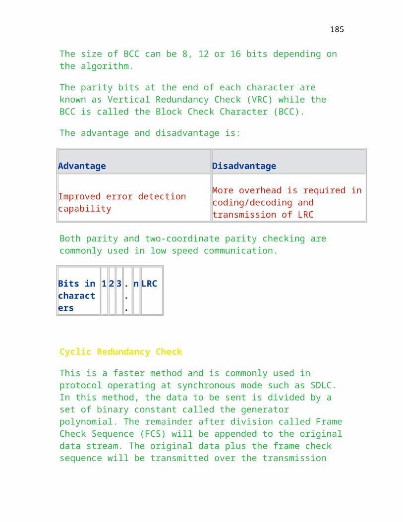
Signalling Rate for LAN
Local Area Network uses Manchester Code to carry data. Unlike RS232D which uses the voltage level to determine the corresponding binary data, it uses its phase change to determine the data. The Manchester Code is shown in Figure . Here, binary 0 means the voltage drops from high level to low level, whereas binary 1 means change from low level to high level. The clocking is also embedded in the signal. That is why no external clock is needed, unlike the synchronous modem or unlike the asynchronous modem where data rate should be configured.
An ordinary telephone line can support data rate up to 16M bps for IBM Token ring. Thin rate (thin coaxial cable) usually support 10M bps for Ethernet. If coaxial cable or optical fibre is used, it can support up to 152M or even higher.
Integrated Services Digital Network (ISDN)
ISDN was originally based on digitized voice at a channel rate of 64 Kbps to support 256 voice levels. ISDN standards were started by the CCITT in 1972. In 1984, the I series recommendation was adopted and it was stated that (CCITT XVIII-228-E 1984):
“...an ISDN is a network...that provides end-to-end digital connectivity to support a wide range of services, including voice and non-voice service...by a limited set of standard multipurpose user-network interfaces...”
Two standards are defined for the physical interface to ISDN, namely the Basic Rate Interface (BRI) defined in CCITT/ITU ISDN I.430 (1993), and the Primary Rate Interface (PRI) in CCITT/ITU I.431 (1993). Both standards define the electrical coding and frame formats. ISDN has been further elaborated since the 1984 recommendations to support a 16 Kbps channel known as D channel for signalling purposes and two 64 Kbps channels known as B channels for basic access. It was also proposed to support higher rates, known as H channels, for primary access which had different configurations for North America (1544 Kbps) and Europe (2048 Kbps). ISDN is a circuit-switched type network but can access packet-switched services by D channels. Two major benefits offered to users are:
185
the common user-network interface for access to a variety of services with faster signalling rates such as the support of high-speed switched data lines and digital voice transmission; and the provision of new services such as the support for concurrent transfer of voice and data.
In summary, the signalling rate for ISDN from the user viewpoint is two 64K bps amounting to to 144K bps. However, the basic transmission rate requires 192K bps of digital transmission capacity. The original intend is to provide voice and data to the desktop terminal/PC at home at this rate without considering the rapid development of high bandwidth network to support multi-media services. We can hire this service from Hong Kong Telecom to support data transfer.
Broadband Integrated Services Digital Network (B-ISDN)
The formal standards bodies developed the standards for ISDN, which is now called the narrowband ISDN, in early 1970 as the predecessor to B-ISDN. The highest rate for a 64 Kpbs based ISDN offered to the user is 1544 Kbps (equivalent to 23B + D64 = 24x64 Kbps) or 2048 Kbps (equivalent to 30B + D64 = 31x64 Kbps). However, there is great demand for the transmission of video signals at bit rates up to 150 Mbps for High Definition Television (HDTV). Many formal standards bodies have been recommending new procedures in order to accelerate the pace of standardisation to that required by industry. This evolves from the practical need for a B-ISDN. ITU-T Recommendation (I.113 1991) stated that B-ISDN is:
“...a service or system requiring transmission...supporting rates greater than the primary rate...”
Three major features related to B-ISDN are (Händel 1994):
enhance the existing signalling rates; define the new broadband user-network interfaces; and be compatible with the existing 64 Kbps ISDN.
However, there are still many issues regarding the types (H and B) and the number of channels incorporated into B-ISDN. ITU-T Recommendation I.120 (1993) further enhanced B-ISDN to support different kinds of applications and customer categories:
186

“...the provision of a wide range of services to a broadband of service to a broad variety of users ...and multipurpose user network interfaces...”
The demand for B-ISDN services is based on optical fibres as in Simmens’ report (1989):
“...solutions are initially needed whereby optical fibres can be economically brought as close as possible to the subscriber, also for already existing services (television, telephony, data transfer)...”
In view of the above description, it is concluded that B-ISDN is an ambitious and practical wide area network designed to become the universal future network at the current signalling rate of 625M bps, which is far beyond T4, 274M bps.
Asynchronous Transfer Mode (ATM)
ATM was proposed in 1986 as the transmission and switching architecture to support broadband services. It was proposed on the assumption that STM’s transmission and switching paradigms, an extension to the narrowband ISDN interface standard, are insufficient to cover multirate, multimode and multicast services. According to ITU-T I.121 (1993),
“Asynchronous Transfer Mode (ATM) is the transfer mode for implementing B-ISDN.”
The first term Asynchronous refers to the sending of data on the network as it arrives. The second term transfer refers to both transmission and switching aspects. Transfer mode is therefore a specific way of transmitting and switching information. The basic transmission unit, according to the definition in I.113 (1991), is: a cell is a fixed length 53-byte packet, which contains a 5-byte header and a 48-byte information field. The header is used for identification by the ATM nodes and the information field is used by the user to carry information. Data is packed into the cells and sent out onto the network to support multiplexed transmission in an irregular pattern. ATM is therefore sometimes called label multiplexing in which the label is used by the receiver to verify which connection the cell is to be associated with. The allocation of cells contrasts with STM which allocates the data in a regular time slot. Cosmas (1994) pointed out that the main benefit of cell switching is statistical multiplexing, which is the simultaneous use of the same communications circuits by many sources on a demand basis.
187
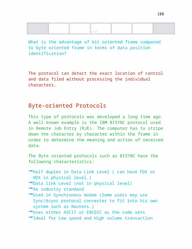
The main limitation of current networks is that they are designed only to support one type of traffic or service. For example, a telephone network makes use of circuit mode to support voice service whilst a data network makes use of packets to transport messages. However, ATM is designed to support a mixture of different kinds of services and combines these two extremes to optimise the bandwidth usage. This method is more efficient compared to the traditional communication mode. In addition, ATM handles the traffic based on demand, which means no traffic, no bandwidth drain. This is in contrast to STM (Synchronous Transfer Mode) which partitions the fixed bandwidth into fixed slot times and wastes the slots when there is no data.
Currently, 44.736 Mbps (DS3), 100 Mbps (Multimode fibre) and two 155.52 Mbps (Based on Synchronous Optical Network and ITU-T Recommendation I.432 (1992) interfaces are specified in ATM Forum (1993).
ATM is the underlying transmission system for B-ISDN and provides the subscriber with communications services over a wide range of bit rates. These include services at a bit rate of the order of 50 bps to 100 Mbps. The current ATM standard allows a user to access telephone networks at speeds over 622 Mbps and will eventually go up to gigabit speeds.
Comparison of Different Physical Layers
Some of the functions of physical layer are:
Generation and Recovery of transmission frame Frame scrambling and descrambling
Comparison of different functionalities in these two sublayers are given below for the four specifications which include 44.736 Mbps, 100 Mbps, 155.52 Mbps (SONET) and 155.52 Mbps (ITU-T).
Physical Media Dependent Sublayer
Layer Function
44.736 Mbps
100 Mbps 155.52 Mbps (SONET)
155.52 Mbps (ITU-T)
Physical Media
Bit timing
o o o o
188
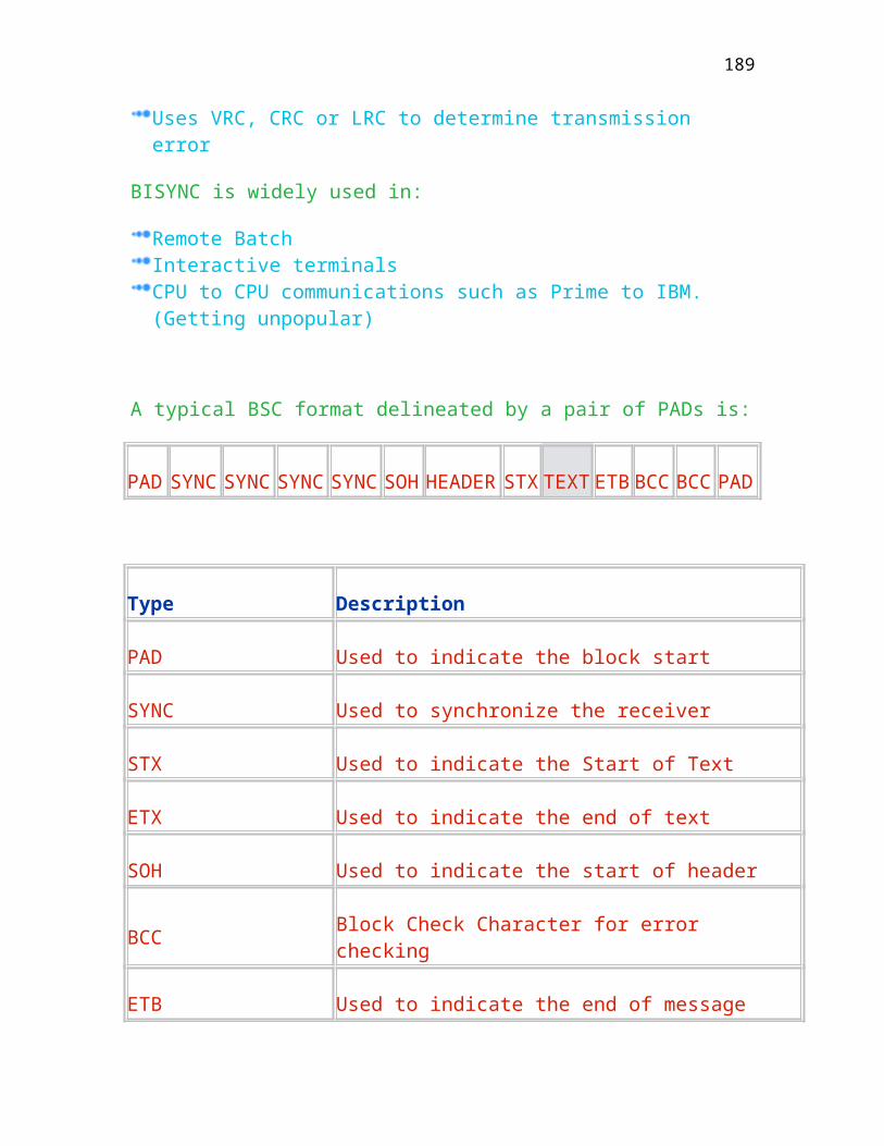
Dependent Sublayer
Line coding Based on ANSI
X3T9.5 (FDDI) committee to use the 5-bit symbol
o o o o
Physical Medium
o o o o
available
ITU-T I Series
An ITU-T committee formerly known as the CCITT was renamed as the Telecommunications standardisation sector. This is a United Nations sponsored treaty organisation and has published approved recommendations in the form of a set of books. The B-ISDN/ATM standards were classified into I and Q series. Figure shows the application scope of I series recommendations.
General aspects related to B-ISDN are specified by:
I.121, Broadband Aspects of ISDN.
The user network interface is specified by:
I.413, B-ISDN User-Network Interface; I.432, B-ISDN User-network Interface - Physical Layer Specification.
The network is monitored by the specification of I.610, B-ISDN Operation and Maintenance Principles and Functions. The traffic control is specified by I.371, Traffic Control and Congestion Control in B-ISDN. Networking aspects are specified by:
B-ISDN General Network Aspects;
Internetworking is specified by:
I.555, Frame Relaying Bearer Service Internetworking; and
189
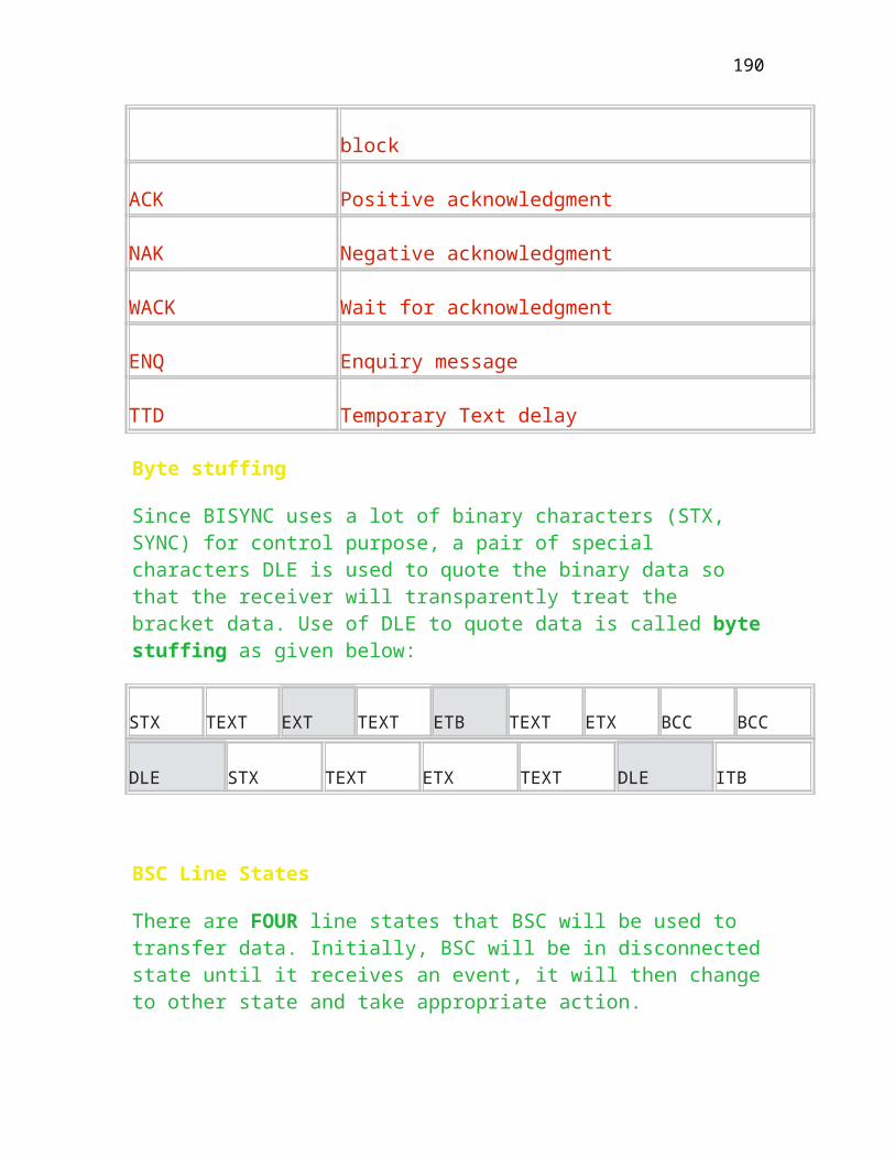
I.580, General Arrangements for Internetworking between B-ISDN and 64 kbps based ISDN.
ITU-T also plans to enhance the existing recommendations or to supplement new recommendations such as I.35BA on B-ISDN availability performance, I.581 on Internetworking Requirements for B-ISDN and G.96x on Access Digital Section for B-ISDN. ITU-T Q series recommendations for B-ISDN are a supplementary set of recommendations mainly for services, signalling, etc.
Bellcore
As early ATM implementations served as a backbone networks, it is able to support the existing Switched MultiMegabit Data Service (SMDS) proposed by Bellcore for the Regional Bell Operating Companies. SMDS is a high-speed connectionless data service at current bit rates up to 155 Mbps intended to be a Metropolitan Area Network (MAN), which can evolve into a country-wide service (Le Boudec 1992). It uses the ITU-T recommendation E.164 global addressing to connect to customer premises network via the Subscriber-Network Interface (SNI) and Network Node Interface (NNI) as shown in Figure A.. SNI is first based on the IEEE 802.6 Distributed Queue Dual Bus (DQDB) MAC protocol and uses a protocol called Subscriber Interface Protocol (SIP) containing roughly three levels up to AAL connectionless data service of ITU-T. It is now run on top of an ATM network. The functions of three levels are summarised below:
The level 1 of SIP is for data transmission and uses DS-1 signaling providing digital transmission rates of 1.544 Mbps or DS-3 at the transmission rates of 54 Mbps. As the need for speed increases to support full motion video, higher speed services like DS-3 are becoming more common. The level 2 of SIP is equivalent to the ATM cell layer and part of the Transmission Convergence Sublayer (TC). The level 3 of SIP is equivalent to AAL of CCITT and switches the frames which cross the interface to their destination.
ATM Forum
190

The ATM Forum was first founded in 1991 in United States by four companies in alphabetical order are Adaptive, Ciso, NTI, and US Sprint to manufacture ATM products that are compliant with international standard. ATM Forum has grown remarkably and has attracted over 550 member organisations from other countries since 1991. It strongly influences the ATM development and has produced the following two specifications in complementary to ITU-T ATM documentation.
B-ISDN intercarrier interface (B-ICI) specification (Version 1.0, August 1993).
Self-examined Questions
Short Questions
What is data rate for T1, T2 and T3?
T1
T2
T3 What is the data rate for ATM switch using optical fibre?
The data rate is
What is the effective data rate for ISDN?
191

The effective rate is
What is the ideal data rate for continuious moving picture?
Chapter Twelve
PC Software Characteristic
This chapter is about the characteristics of common PC software. Nowadays,
most PCs have a basic configuration including serial card for asynchronous communication. Some PCs have integrated especially Laptop PCs modems operating at the speed of 56K bps. With data processing and communications power, PCs can off-load the central computers by downloading raw data from central and then process locally, or uploading data to central after processing.
Understand the basic PC software such as PC term, Proc comm.
Communication S/W packages are usually programmes that
allow your PC to send and receive data through the telephone line via modem, They serve three primary functions:
to access a larger computer, such as a minicomputer or mainframe computer or through a LAN card to access a intranet/LAN server, as if the PCs were a terminal on that computer or a browser. An extension of terminal emulation is the ability to get data from the mainframe and put it in the PC environment. The telnet is always used. Using FTP to perform file transfer. to access Internet or Intranet server acting like a browser.
The characteristics of using telent are:
192

A typical application of PC and communication S/W is electronics mail services. Most communication S/W packages make the PC to emulate terminal(s) such as VT100 (Virtual Terminal and type 100), VT52, IBM3101 etc. Each terminal has unique characteristics, and the communication program must make the PC emulate the specific terminal precisely. The information sent from the PC to the host computer must be in the form expected by the host such as both are using ASCII or EBCDIC. Certain communication S/W packages need special H/W card such as SDLC card (Synchronous Data Link used by IBM) other than the serial card for operation, especially those for synchronous mode of operation (e.g. X.25, bisync, SDLC etc.) There are S/W package that makes a PC to emulate a FAX terminal such as WIN FAX or GAMMA FAX package as well. There are also special purpose communication S/Ws that make PCs become bulletin board hosts, central master controllers, Internet server (NT 4.+), point-of-sale terminals, etc. They are usually developed by equipment manufacturers, S/W houses, or users for specific applications, and are usually not available from the commercial S/W market.
Characteristics of Command/Menu Driven
Menu driven characteristics
The user friendliness in a communication S/W can assume various forms. The programme designer has to weight the simplicity of user interface versus programme flexibility and consider the type of user community. In a commercial programme, the designer also wants to maximise the number of potential users, who range from beginners to sophisticated users. The characteristics are:
The easiest way to interact with the user is by presenting a few simple choices or an introductory menu on the screen. This has been adopted by most communication S/W. As the number of choices displayed on the screen is limited to between 15 & 20, the programme can display additional menus after the initial selection. A menu-driven programme assumes only a minimal knowledge on the part of the user, as choices are always displayed on the screen, but it has limitation. On-line “help” facilities are usually available.
193
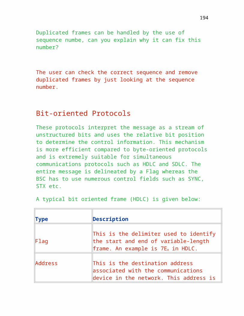
A large number of choices leads to hierarchical menus which may make a menu-driven program very cumbersome.
Command Driven
Instead of choosing from a limited number of options displayed on the screen in a menu, most communication S/Ws can also be driven by issuing short commands as well. The user then gains considerable flexibility at the expenses of having to remember the various commands, through on-line “HELP” facilities. For instance, the popular Crosstalk and Mirror programmes combine menu-driven and command driven approaches by responding to large dictionary of user commands and by displaying the most important ones in a menu on the screen.
Programmability
Many general purpose communication S/W packages support programming as well, by offering programming languages. As the programming languages are communications oriented, they are better than general purpose languages as BASIC especially for the development of simple communication application. The characteristics are:
The associated configuration and programmes are usually called command and script files. The command file is executed before a connection with a remote computer is established. It can be considered a static file. A command file contains all parameters required to establish a data connection, such as the telephone number, number of data bits and stop bits, parity information etc. The dynamic script file executes in response to queries from the remote computer after the connection is established. The script file may contain the user’s name and password for the particular service and standard responses to various questions asked by the information service. The script is written in special language, called a script language, which varies from one data communication S/W to another. By using the script file, a casual user does not need to have any familiarity with the data communications parameters and has only to know which function button to press on the keyboard to start a data connection.
194
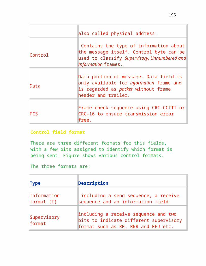
Examples of Common Communication S/W
A few common PC communications software packages are listed for comparison including Crosstalk, Procomm, Mirror and Smartcom. Some are pretty old packages.
Crosstalk
It is a general purpose asynchronous communication software ware using serial card. It has strong terminals emulation capability including DEC, DASHER and Tel Video terminals. The characteristics are:
It supports the commonly used file transfer protocols including Kermit, Xmodem, Ymodem and Compuserve-B It introduces a new file transfer protocol called DART. The programming language available is called CASL (Crosstalk Application Script Language), which is very powerful language. It contains a built-in text editor and supports answering incoming calls from other computers. It is capable of managing concurrent communication session and supports Tymnet X.PC via asynchronous serial port. It supports IBM 3278/3279 terminals models 2, 3, 4 and 5 emulation with IRMA communications board. It supports IBM 5251, 5291, 5292 an 5256 terminals/printers emulation with SmartAler communication board.
Procomm
It is a general asynchronous communication software using serial card. It has strong terminals emulation capability and supports a lot of file transfer protocols. The programming language available is called ASPECT. It includes a fast text editor called PCEDIT. The Script language supports HOST mode that lets remote user log on to an unattended computer and use it like a Bulletin Board System. It also supports background operation in Multitasking environments.
Mirror
195

It is a general purpose asynchronous communication software using serial card. It is designed and written to be a clone of the Crosstalk XVI programme. It has a strong terminal emulation capability and supports many of the more popular file transfer protocols. The communications oriented programming language supported is called SCRIPT. It has a built-in text editor with Wordstar-like command structure. It provides an answer mode processing which prepares the microcomputer to play the role of unattended host computer system. It also supports background processing.
Smartcom
It supports asynchronous communication software using serial card. It is specifically designed to work with Hayes smartmodem products or V-series system products. It supports common terminals emulation and limited file transfer protocols. It provides remote access capability, which requires both the originating and answering system. It allows the originator of a call to take control of the answer’s programme from a remote location. It has a pre-configured communication sets available to access the popular information services such as CompuServe, DJN/R etc.
Example of Hyperterminal
Windows 95/98 provide a list of software for terminal emulation. Simply click the menu of accessories, you will find the diagram as shown in Figure . Here, it has four icons with different terminal characteristics. If you click AT&T mail (a big telecommunication corporation in US), and select the mail properties, you need to configure your PC which port you need to connect to the modem, the phone number of the remote site and its area code. The area code for Hong Kong is 852. The diagram is shown in Figure
You can emulate the type of terminal characteristics as shown in Figure . Here, you an specify the type of emulation such as ANSI, TTY, VT100 etc. Each of them has similar characteristics with slight variation.
You can perform the file transfer by clicking the send icon as shown in Figure . Here, you have to specify one of the PC transfer protocols, namely, Xmodem, Ymodem, Ymodem-G, Zmodem and Kermit. They are the commonly used protocols in PC environment with different message size and handshaking. Of
196

course, both sides must configure the same protocol. Otherwise, it cannot communicate.
Figure shows the how to configure a modem including the port number, maximum speed and the volume of speaker. .
Figure shows the data bit (7 bits), parity bit and also the stop bit in your data format. here, the stop bit can be 1, 1.5 and 2 bits. 2-bit stop bit means it has to wait the duration of 2 bits before it receives a new one. .
197

Chapter Thirteen
Future Data Communications
This chapter is about the prospective of data communications. It has been
observed that for the past few years, data communications
Understand the prospective of communications network
Future Wireless Communication Concerns
As the telecommunication infrastructure gets larger and larger, new problems and issues need to be resolved. More and more countries, companies, and people are using wireless telecommunication systems. The increased demand for communication products that serve unique communication functions is pushing technology to the limit.
New technologies and industries are being created as a result of people striving to find solutions to communication needs. The solutions address such problems as traffic jams on the spectrum, reduced orbital space for satellites, and pollution of the air waves.
List two problems we foresee facing the wireless communication industry?
One of the problem is the limitation of frequency channels. Curently, it uses celluar method to divide the regions into a number of cells and re-use the frequency after a certain limitation. The smaller the cells the more the channels and the higher the badnwidth. Imagine that you now have a mobile phone (currently can support up to 9600 bps), which can support 20 M bps, what you do think you can do with this high bandwidth. You can combine multi-media together pefrom e-business etc. One main problem is the availability of frequencies on the spectrum. The spectrum has become crowded. Another is the number of satellites in orbitonly so many will fit in our atmosphere. Also, satellites are very expensive and have a relatively short life span of five to ten years. New technologies will be needed to solve both these problems in order to maximize the use of the spectrum and bandwidth.
198
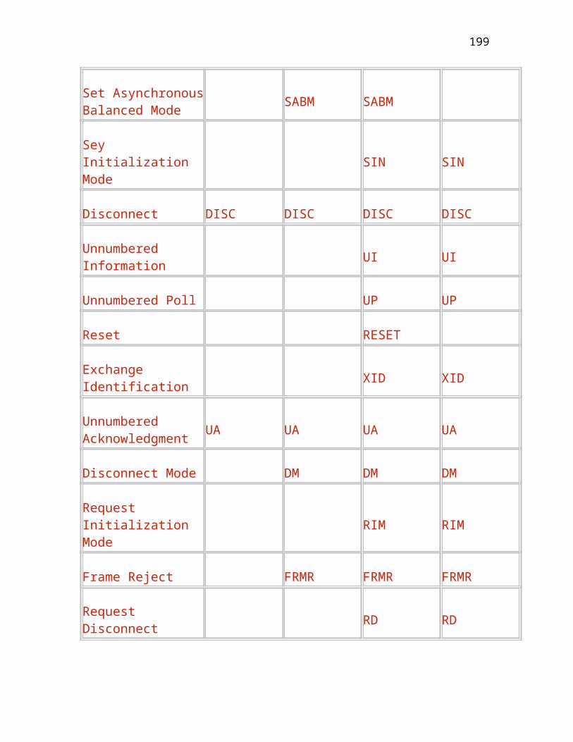
Pollution of the air waves is becoming a major problem. Electrical appliances in your home, remote control systems, radio, TV, and microwaves all fill the air around you. Wireless devices have been blamed for major accidents. An example is cellular phones interfering with aircraft guidance and control systems.
Can you think of another place where a cellular phone is not allowed? Briefly explain why.
The interference affets the equipment such as hospital, aeroplane.
Health concerns for the users of these products have also been an issue. Although it is not scientifically proven, there have been some cases where individuals feel that they developed a brain tumor from constant use of a cellular phone.
Digital communications is growing to meet the needs of increasing bandwidth. Satellites are now able to carry tens of thousands of signals simultaneously rather than only 300, as was the case in 1960. One of the fastest growing industries is that of shielding objects, machinery, and people from unnecessary electromagnetic wave exposure. This is one reason many microwave repeaters are being replaced with fibre optic cable. It is shielded communication.
Digital radio will provide consumers with clear, almost-noise-free radio sound. It takes up less spectrum space and will use a range of spectrum that is not cluttered like AM and FM radio spectrums. The frequency range used by digital radio is known as the L-band.
Search to find information about this new technology and share it with your fellow students in the conferencing sessions or using ICQ.
Another new technology is Personal Communication Services (PCS), which is a wireless communication service that takes the concept of cellular into the future. PCS produces crystal-clear quality sound, data (faxes, modem), and video. It is totally digital, offers great communication security, is clearer than a cellular phone, and has features such as call waiting, voice mail, call display, and text display.
199

PCS and digital radio are just two of the new emerging technologies. There are many others. DTHS (Direct-to-Home Satellite), and satellite modems are examples of what is coming that will have a major impact on society.
Collect information about future technologies. Use the Internet search engines and locate the wireless gallery. Use your lesson Resources file for other sources.
Example
A new, three-dimensional system for taking ultrasound images of a baby in the womb allows doctors and parents a clear view of the fetus moving. Doctors at the University of Tokyo’s medical school said they have improved their equipment by adding an extra three-dimensional probe to an existing scanner and tried it out on 66 normal fetuses. It produced an image every eight seconds, which could be viewed as a sort of slow-motion video. Investigate how ultrasound is used to create images of babies in the womb.
Past, current and future communication
Present computing can be characterized primarily by four well-established approaches: Time sharing, transaction, main frame and Client-server. Client-server systems exist recently and are growing rapidly in quantity. Banking is an example of an application area where communications needs have included the transfer of large-files, transactions-like transfers, and time-sharing.
Mainframe Computing system
In mainframe systems, peripherals are directly connected to the processors through Front End processor. The characteristics are:
Networks are used for moving large files between the mass storage peripherals on these systems. Computers are loosely coupled to each other by use of communications lines. The file size is usually from kilobytes upward and the response time is in the order of seconds for small files and minutes for large files as shown in Figure . The only choice available for long haul transfer is the existing telecommunication system which is connected oriented, a connection is
200

mandatory in order to transfer data. Traffic is not particularly bursty relative to the time that a connection exists The classes of protocols used are LAPB, High-level Data link control ((HDLC), Synchronous Data link control (SDLC), Transmission Control Protocol(TCP) and Transport Protocol4 (TP4).
Figure is the diagram showing the relationship between the size of end-user and the needed response time.
Terminal time-sharing Computer Systems
For theses systems, dumb character-oriented terminals are typically in locations remote to a central computer running a multitasking system The characteristics are:
Traffic from the terminal to the computer is often a few bytes at a time representing a few characters at a speed typed by the user. Average bit rate is not likely to exceed 200 bits per second averaged over a minute. Asynchronous line speed of 1200 or 2400 bits per second are adequate for this type of communication. In Hong Kong, the commonly achievable line speed is 56K bits per second. Traffic from the computer to the terminal is more demanding with up to a full screen such as 25x80 bytes or 20,000 bits burst to the screen at a few seconds. As the terminals are dumb, a communication connection is mandatory.
Transaction Based Computer Systems
Using the graph in Figure , it is located between the time-sharing and mainframe clouds. Semi-intelligent terminals or stations (PC/Workstations) are connected via a communication network to a multitasking mainframe computer. The characteristics are:
Traffic from the station to the computer may range from a few bytes to an entire screen of information. Usually, the station handles most human interaction and periodically sends updated and validated information to the main frame. Station to computer work units range from a few tens of bytes to 25x132 bytes or 33,000 bits burst in a few seconds.
201

In many of these systems the network is a multi-drop cable with a number of stations and a single attached computer such as IBM 3270 systems. Or a point-to-point connection such as PC to VAX. In such system, the station is connected at a distance via common carrier facilities, modems and connection-oriented dedicated or dial-up network. A polled half duplex protocol such as BSC or SDLC or Asynchronous are used.
Client-server Model
A typical example of client server model is the Internet (User to Business)/Intranet (user to Business with limited location) or Extranet (Business to Business). Currently, the line speed is limited to 56K bps for ordinary telephone line but can be extend to 1.5M bps for IMS service or Cable modem for (Cable TV) for 10M bps, it is expected that wireless data communication will soon (by 2002) provides a data rate up to 2M bps or even up to 20M bps. This means that any mobile phone can hook up to a Latop computer to visualise graphics, video, voice etc. through the Internet. The currently line speed provided by mobile phone is 9600 bps and will reach to 14.4 k bps this year. that it
Systems Software
While single task operating systems such as MSDOS will be obsolete except for old development because of the huge embedded base of application software (a certain large bank in Hong Kong still uses self-developed MSDOS-based e-mail system), multitasking operating systems such as UNIX, OS/2, NT will be getting popularity. This will also be accelerated by factors of demanding more user-friendly end users interface such as windowing systems. Figure shows the MIPS and the size of Real Memory against the size of CPU chips.
The characteristics are:
For the multitasking operating systems, virtual memory strategies using paging and caching are commonplace. Swapping operations will continue but be used less often. File management and procedure calls will continue to be common operations Multi-media including video and voice will continually receive much attention What you see is what you get word processing and desktop publishing is
202

widely used due to the growth in windowing Remote Procedure Call to access the remote computer through a network has grown rapidly in popularity. This has happened such as the use of browser to retrieve data through the remote server.
Self-examined Question
Once data has been converted to digital code, it can be easily altered by the user. For example, photographs can be scanned, digitalized then transmitted and altered. Knowing this, can we assume photographs are proof of anything? Can they still be valid sources of court documentation? In terms of news reporting, what ethics are involved here?
Think of the jobs and professions that benefit from pagers and mobile phones. What are the disadvantages?
203