
Data Communications and Networking-Chapter 20
55
20.1 Chapter 20 Network Layer: Internet Protocol Copyright © The McGraw-Hill Companies, Inc. Permission required for reproduction or display.
-
Upload
ajayrenganathan -
Category
Documents
-
view
136 -
download
1
description
Network Layer: Internet Protocol
Transcript of Data Communications and Networking-Chapter 20
20.1
Chapter 20
Network Layer: Internet Protocol
Copyright © The McGraw-Hill Companies, Inc. Permission required for reproduction or display.

20.2
20-1 INTERNETWORKING
In this section, we discuss internetworking, connecting
networks together to make an internetwork or an
internet.
Need for Network Layer
Internet as a Datagram Network
Internet as a Connectionless Network
Topics discussed in this section:

20.3
Figure 20.1 Links between two hosts
20.4
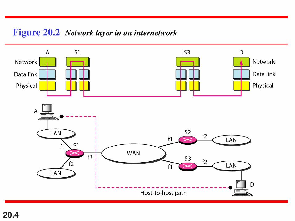
Figure 20.2 Network layer in an internetwork

20.5
Figure 20.3 Network layer at the source, router, and destination

20.6
Figure 20.3 Network layer at the source, router, and destination (continued)
20.7
Switching at the network layer in the Internet uses the datagram approach to
packet switching.
Note

20.8
Communication at the network layer in the Internet is connectionless.
Note
20.9
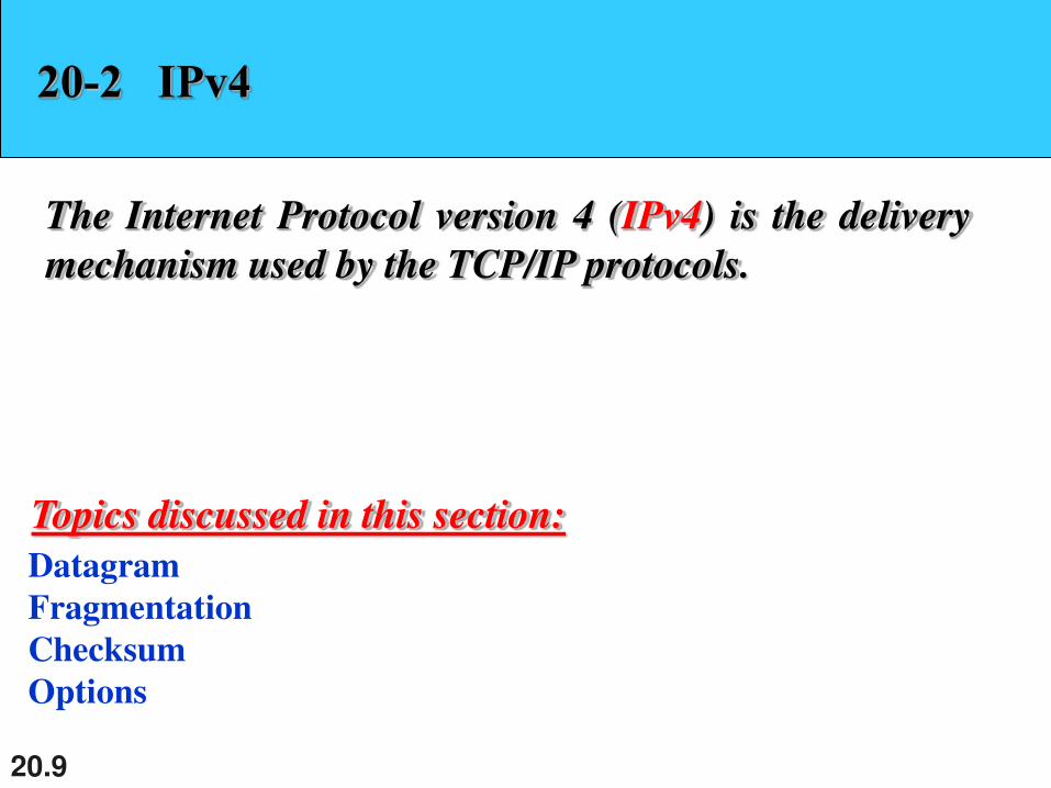
20-2 IPv4
The Internet Protocol version 4 (IPv4) is the delivery
mechanism used by the TCP/IP protocols.
Datagram
Fragmentation
Checksum
Options
Topics discussed in this section:
20.10
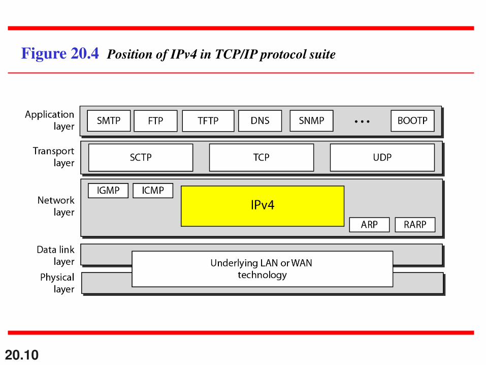
Figure 20.4 Position of IPv4 in TCP/IP protocol suite
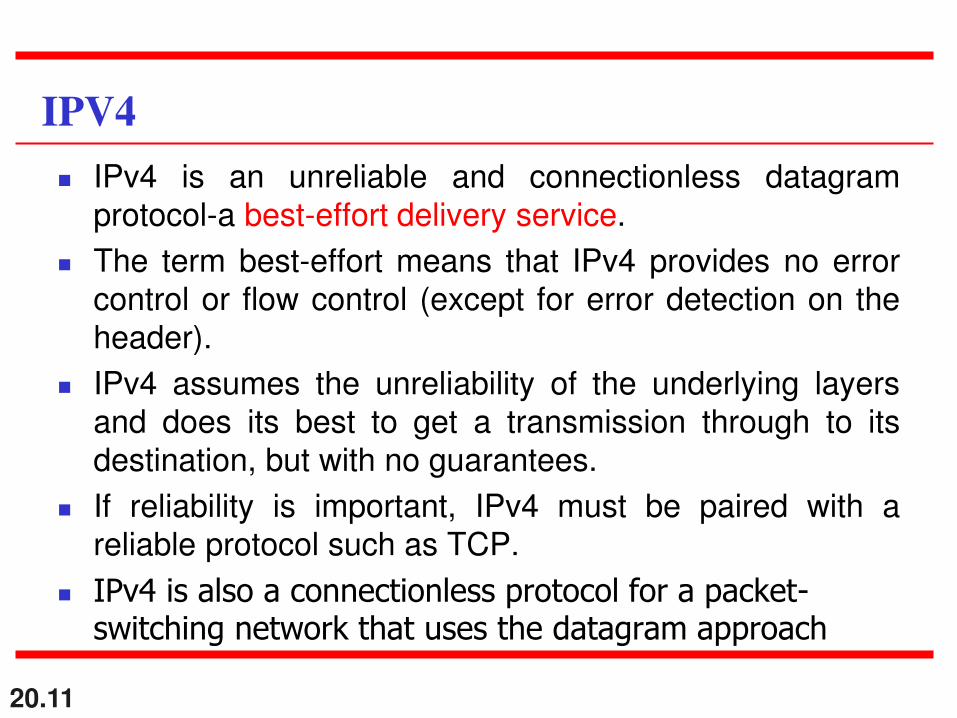
IPv4 is an unreliable and connectionless datagram
protocol-a best-effort delivery service.
The term best-effort means that IPv4 provides no error
control or flow control (except for error detection on the
header).
IPv4 assumes the unreliability of the underlying layers
and does its best to get a transmission through to its
destination, but with no guarantees.
If reliability is important, IPv4 must be paired with a
reliable protocol such as TCP.
IPv4 is also a connectionless protocol for a packet-switching network that uses the datagram approach
20.11
IPV4

20.12
Figure 20.5 IPv4 datagram format
20.13
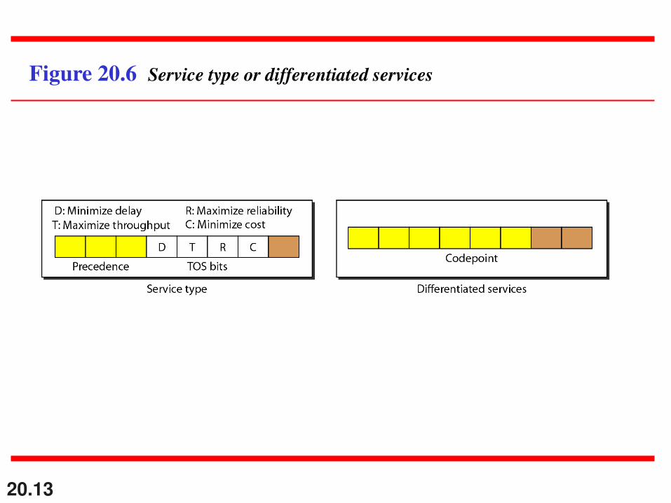
Figure 20.6 Service type or differentiated services

20.14
The precedence subfield was part of version 4, but never used.
Note

20.15
Table 20.1 Types of service
20.16
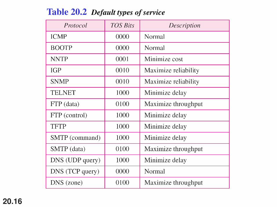
Table 20.2 Default types of service
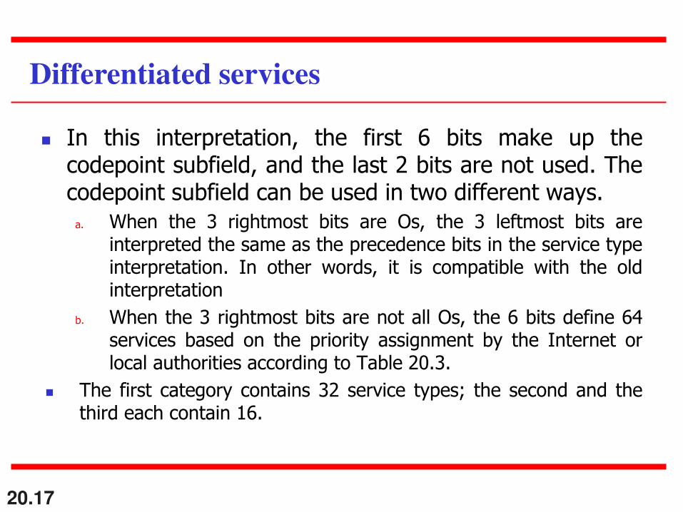
In this interpretation, the first 6 bits make up the codepoint subfield, and the last 2 bits are not used. The codepoint subfield can be used in two different ways.
a. When the 3 rightmost bits are Os, the 3 leftmost bits are interpreted the same as the precedence bits in the service type interpretation. In other words, it is compatible with the old interpretation
b. When the 3 rightmost bits are not all Os, the 6 bits define 64 services based on the priority assignment by the Internet or local authorities according to Table 20.3.
The first category contains 32 service types; the second and the third each contain 16.
20.17
Differentiated services
20.19
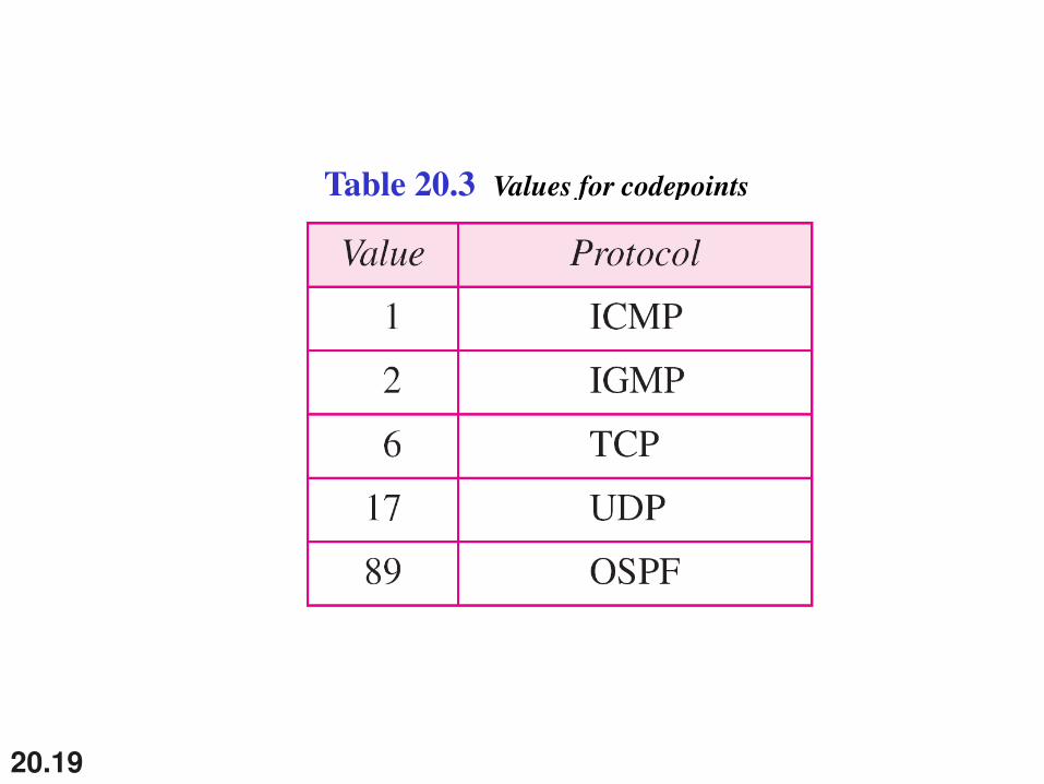
Table 20.3 Values for codepoints
20.20
The total length field defines the total length of the datagram including the
header.
Note

20.21
Figure 20.7 Encapsulation of a small datagram in an Ethernet frame

20.22
Figure 20.8 Protocol field and encapsulated data

20.23
Table 20.4 Protocol values

20.24
An IPv4 packet has arrived with the first 8 bits as shown:
01000010
The receiver discards the packet. Why?
Solution
There is an error in this packet. The 4 leftmost bits (0100)
show the version, which is correct. The next 4 bits (0010)
show an invalid header length (2 × 4 = 8). The minimum
number of bytes in the header must be 20. The packet has
been corrupted in transmission.
Example 20.1

20.25
In an IPv4 packet, the value of HLEN is 1000 in binary.
How many bytes of options are being carried by this
packet?
Solution
The HLEN value is 8, which means the total number of
bytes in the header is 8 × 4, or 32 bytes. The first 20 bytes
are the base header, the next 12 bytes are the options.
Example 20.2
20.26
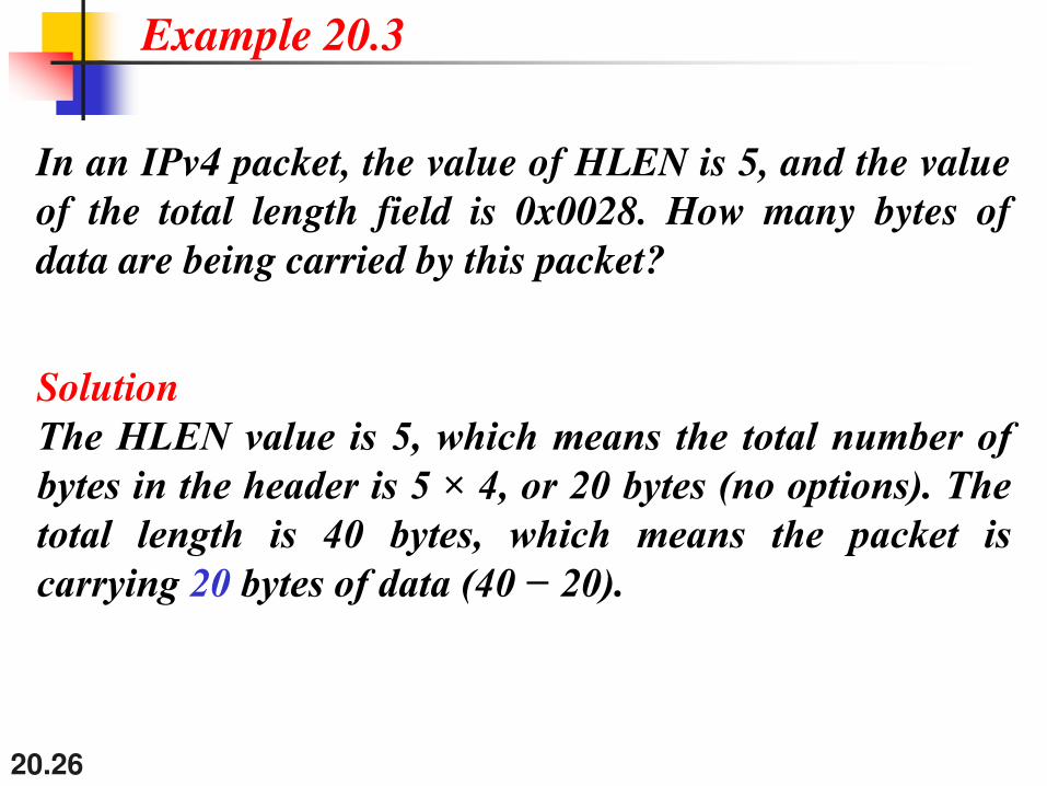
In an IPv4 packet, the value of HLEN is 5, and the value
of the total length field is 0x0028. How many bytes of
data are being carried by this packet?
Solution
The HLEN value is 5, which means the total number of
bytes in the header is 5 × 4, or 20 bytes (no options). The
total length is 40 bytes, which means the packet is
carrying 20 bytes of data (40 − 20).
Example 20.3
20.27
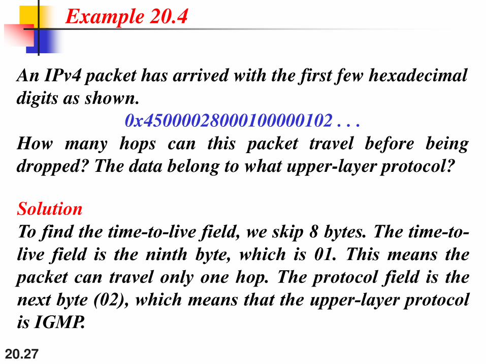
An IPv4 packet has arrived with the first few hexadecimal
digits as shown.
0x45000028000100000102 . . .
How many hops can this packet travel before being
dropped? The data belong to what upper-layer protocol?
Solution
To find the time-to-live field, we skip 8 bytes. The time-to-
live field is the ninth byte, which is 01. This means the
packet can travel only one hop. The protocol field is the
next byte (02), which means that the upper-layer protocol
is IGMP.
Example 20.4
A datagram can travel through different networks.
Each router decapsulates the IPv4 datagram from the frame it
receives, processes it, and then encapsulates it in another
frame.
The format and size of the received frame depend on the
protocol used by the physical network through which the
frame has just travelled.
The format and size of the sent frame depend on the protocol
used by the physical network through which the frame is
going to travel.
For example, if a router connects a LAN to a WAN, it receives
a frame in the LAN format and sends a frame in the WAN
format.
20.28
Fragmentation

20.29
Figure 20.9 Maximum transfer unit (MTU)

20.30
Table 20.5 MTUs for some networks

20.31
Figure 20.10 Flags used in fragmentation
20.32
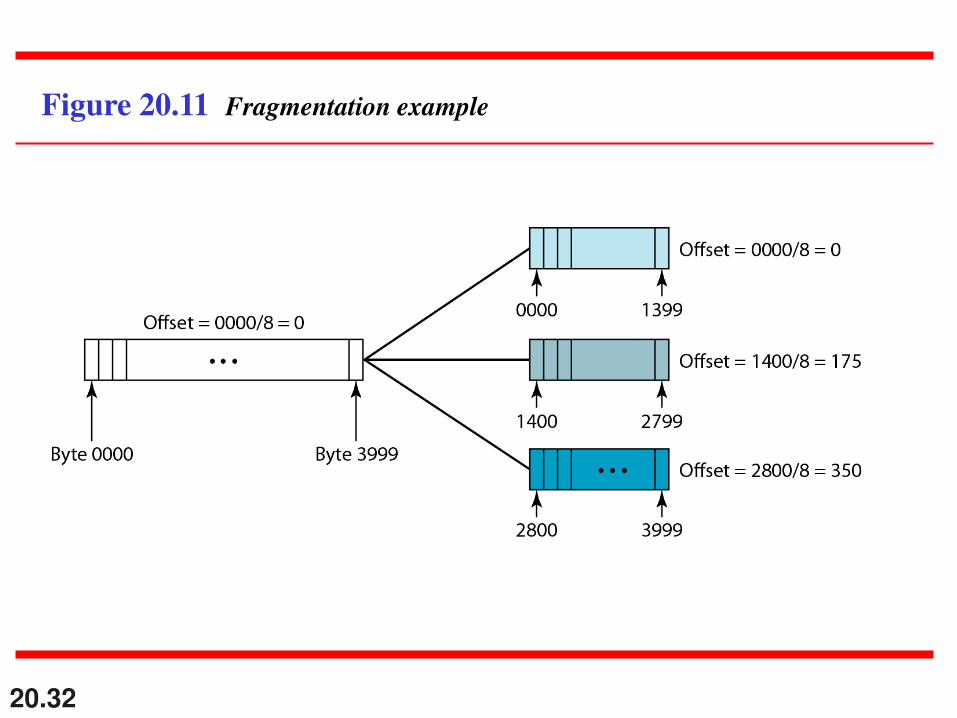
Figure 20.11 Fragmentation example
20.33
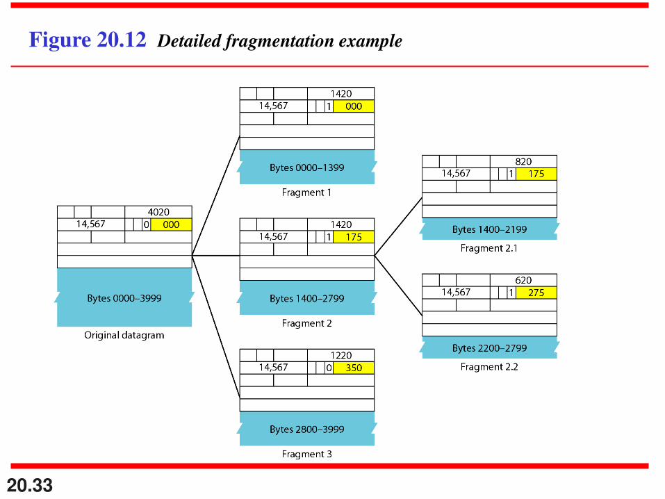
Figure 20.12 Detailed fragmentation example

20.34
A packet has arrived with an M bit value of 0. Is this the
first fragment, the last fragment, or a middle fragment?
Do we know if the packet was fragmented?
Solution
If the M bit is 0, it means that there are no more
fragments; the fragment is the last one. However, we
cannot say if the original packet was fragmented or not. A
non-fragmented packet is considered the last fragment.
Example 20.5

20.35
A packet has arrived with an M bit value of 1. Is this the
first fragment, the last fragment, or a middle fragment?
Do we know if the packet was fragmented?
Solution
If the M bit is 1, it means that there is at least one more
fragment. This fragment can be the first one or a middle
one, but not the last one. We don’t know if it is the first
one or a middle one; we need more information (the
value of the fragmentation offset).
Example 20.6
20.36
A packet has arrived with an M bit value of 1 and a
fragmentation offset value of 0. Is this the first fragment,
the last fragment, or a middle fragment?
Solution
Because the M bit is 1, it is either the first fragment or a
middle one. Because the offset value is 0, it is the first
fragment.
Example 20.7

20.37
A packet has arrived in which the offset value is 100.
What is the number of the first byte? Do we know the
number of the last byte?
Solution
To find the number of the first byte, we multiply the offset
value by 8. This means that the first byte number is 800.
We cannot determine the number of the last byte unless
we know the length.
Example 20.8
20.38
A packet has arrived in which the offset value is 100, the
value of HLEN is 5, and the value of the total length field
is 100. What are the numbers of the first byte and the last
byte?
Solution
The first byte number is 100 × 8 = 800. The total length is
100 bytes, and the header length is 20 bytes (5 × 4), which
means that there are 80 bytes in this datagram. If the first
byte number is 800, the last byte number must be 879.
Example 20.9

20.39
Figure 20.13 shows an example of a checksum
calculation for an IPv4 header without options. The
header is divided into 16-bit sections. All the sections are
added and the sum is complemented. The result is
inserted in the checksum field.
Example 20.10

20.40
Figure 20.13 Example of checksum calculation in IPv4
20.41
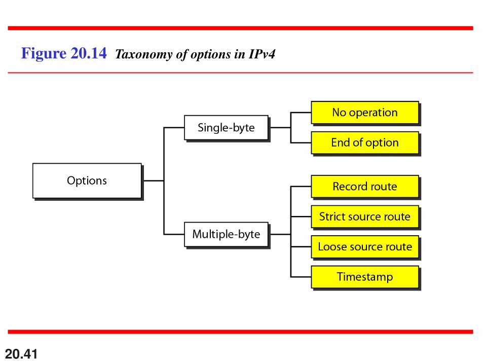
Figure 20.14 Taxonomy of options in IPv4

20.42
20-3 IPv6
The network layer protocol in the TCP/IP protocol
suite is currently IPv4. Although IPv4 is well designed,
data communication has evolved since the inception of
IPv4 in the 1970s. IPv4 has some deficiencies that
make it unsuitable for the fast-growing Internet.
Advantages
Packet Format
Extension Headers
Topics discussed in this section:

20.43
Figure 20.15 IPv6 datagram header and payload

20.44
Figure 20.16 Format of an IPv6 datagram
20.45
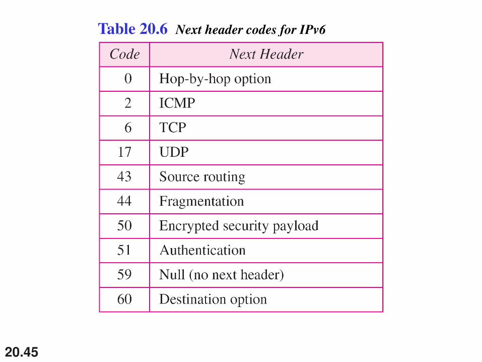
Table 20.6 Next header codes for IPv6

20.46
Table 20.7 Priorities for congestion-controlled traffic
20.47
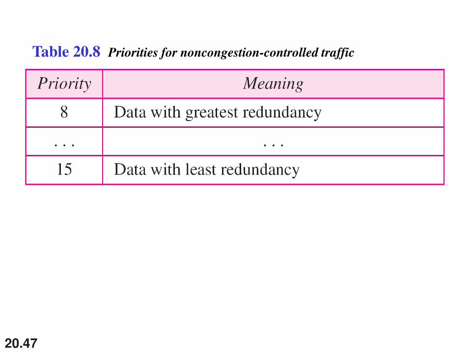
Table 20.8 Priorities for noncongestion-controlled traffic
20.48
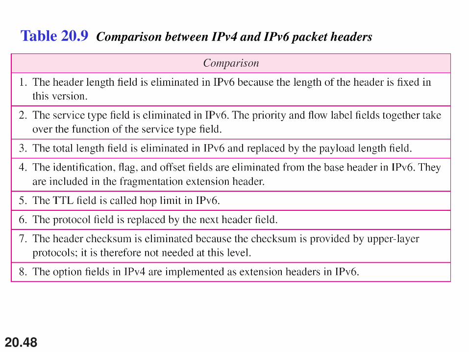
Table 20.9 Comparison between IPv4 and IPv6 packet headers

20.49
Figure 20.17 Extension header types

20.50
Table 20.10 Comparison between IPv4 options and IPv6 extension headers
20.51
20-4 TRANSITION FROM IPv4 TO IPv6
Because of the huge number of systems on the
Internet, the transition from IPv4 to IPv6 cannot
happen suddenly. It takes a considerable amount of
time before every system in the Internet can move from
IPv4 to IPv6. The transition must be smooth to prevent
any problems between IPv4 and IPv6 systems.
Dual Stack
Tunneling
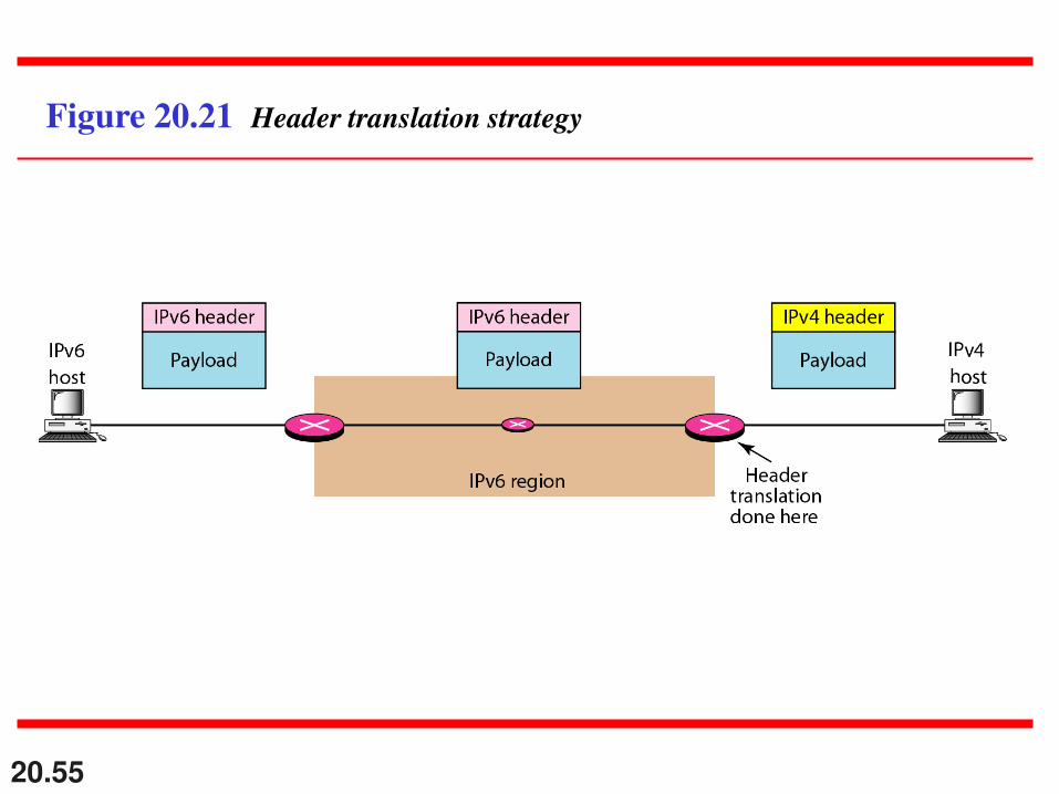
Header Translation
Topics discussed in this section:

20.52
Figure 20.18 Three transition strategies
20.53
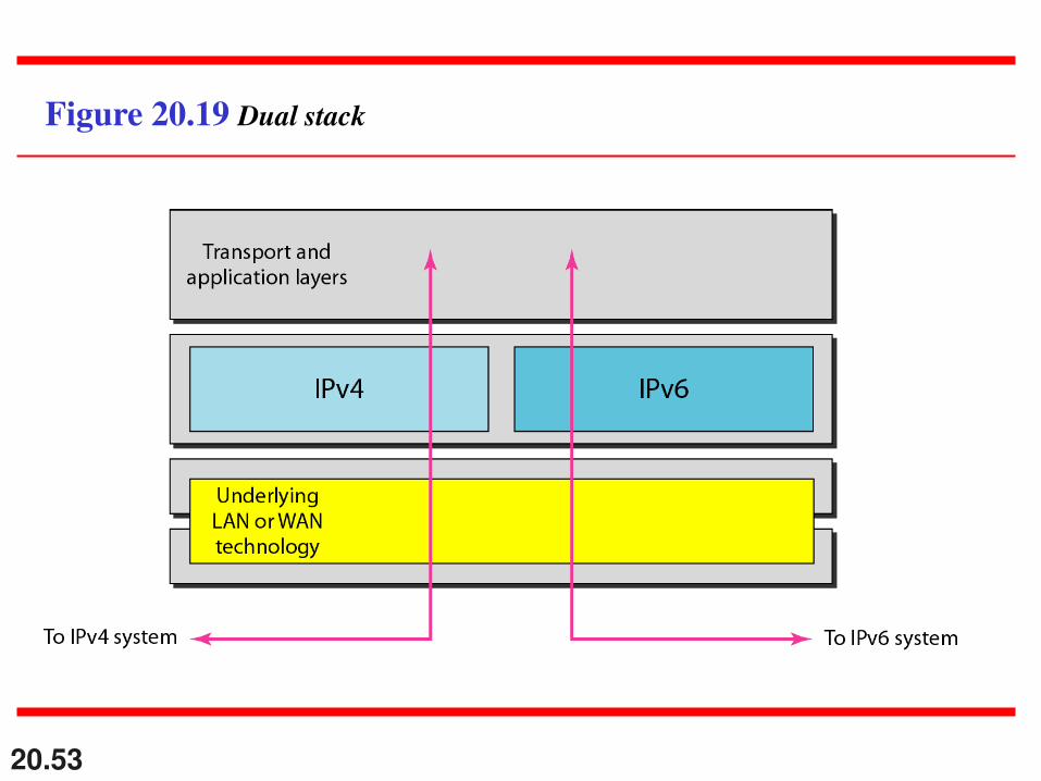
Figure 20.19 Dual stack

20.54
Figure 20.20 Tunneling strategy
20.55
Figure 20.21 Header translation strategy

20.56
Table 20.11 Header translation