NIMS Preparedness IS-0700.A – October 2014 Visual 3.1 NIMS Preparedness Unit 3.

1
Guidance Document n°3 on the harmonised free allocation methodology for the EU ETS post 2020
Data collection guidance Final version issued on 15 February 2019 The guidance does not represent an official position of the Commission and is not legally binding. However, this guidance aims to clarify the requirements established in the EU ETS Directive and the FAR and is essential to understanding those legally binding rules.
EUROPEAN COMMISSION DIRECTORATE-GENERAL CLIMATE ACTION Directorate B - European and International Carbon Markets
2
CONTENTS 1 Introduction .............................................................................................................. 4
1.1 Scope of this Guidance Document ............................................................ 4
2 Objective ................................................................................................................... 5
2.1 Background to data collection .................................................................. 5
2.2 Link to NIMs baseline data template and other documents .................... 5
2.3 Relevance of different sections for different installations ....................... 6
2.4 General guidelines on the use of the template ........................................ 8
3 MS-specific parameters in NIMs baseline data template ...................................... 10
4 Process of data collection for operators ................................................................ 11
5 Process of filling in the template ............................................................................ 12
A “Installation Data” – General information on this report ...................................... 14
A.I Identification of the Installation ............................................................. 14
A.II Information on this baseline data report ............................................... 18
A.III List of sub-installations ........................................................................... 20
A.IV List of technical connections ................................................................... 22
B+C “Annual Emissions Data” for the relevant Year ...................................... 24
B+C.I General Guidance for source stream data .............................................. 24
B+C.II Source streams and emission sources .................................................... 24
D “Emissions” – Attribution of emissions .................................................................. 26
D.I Total Direct Greenhouse Gas Emissions and Energy Input from Fuels .. 26
D.II Attribution of emissions to sub-installations .......................................... 27
D.III Cogeneration tool ................................................................................... 28
D.IV Waste gas tool......................................................................................... 31
E “Energy Flows” – Data on energy input, measurable heat and electricity ............ 35
E.I Energy input from fuels .......................................................................... 35
E.II Measurable heat ..................................................................................... 37
E.III Waste gas balance .................................................................................. 43
E.IV Electricity ................................................................................................. 44
F “Product BM” – Sub-installation data relating to product benchmarks ................ 46
F.I Historical Activity Levels and disaggregated production details ............ 46
G “Fall-back” – Sub-installation data relating to fall-back sub-installations ............. 57
G.I Historic Activity Levels and disaggregated production details ............... 57
H “Special BM” – Special data for some product benchmarks .................................. 66
H.I CWT (Refinery products) ......................................................................... 66
H.II Lime ......................................................................................................... 67
H.III Dolime ..................................................................................................... 68
H.IV Steam cracking ........................................................................................ 69
H.V Aromatics ................................................................................................ 70
H.VI Hydrogen ................................................................................................. 71
H.VII Synthesis gas ........................................................................................... 72
H.VIII Ethylene oxide/glycols ............................................................................ 73

3
H.IX Vinyl chloride monomer (VCM) .............................................................. 73
I “MS specific” – Additional data requirements by the Member State ................... 75
I.I To be defined by the Member State ....................................................... 75
J “Comments” – Comments and further information .............................................. 76
J.I Documents supporting this report ......................................................... 76
J.II Free space for all kinds of supplemental information ............................ 76
K “Summary” – Overview of most important data ................................................... 77
K.I Installation data ...................................................................................... 77
K.II Baseline period and eligibility ................................................................. 77
K.III Emissions and Energy Flows ................................................................... 77
K.IV Sub-installation data relevant for allocation purposes .......................... 78
K.V Calculation of preliminary annual amount of allowances allocated free of charge 79
Annex A: Comparison with 2011 Guidance Document 3 ............................................... 81

4
1 Introduction
1.1 Scope of this Guidance Document
This guidance document is part of a group of documents1, which are intended to support Member States, and their Competent Authorities, in the consistent implementation throughout the Union of the allocation methodology for the fourth trading period of the EU ETS (post 2020), established by the Delegated Regulation of the Commission XX/XX on “Transitional Union-wide rules for harmonised free allocation of emission allowances pursuant to Article 10a of the EU ETS Directive” (FAR). Guidance Document 3 on Data Collection may provide support when performing the data collection pursuant to Article 14 of the FAR in order to define the complete list of installations as well as to calculate any free allocation to be determined for the National Implementing Measures (NIMs) pursuant to Article 11(1) of the Directive 2003/87/EC. Note that this document only covers the transitional harmonised free allocation to industry under Article 10a of the EU ETS Directive. Any allocation under Article 10c (“Option for transitional free allocation for the modernisation of the energy sector”) is outside the scope of this document. Furthermore, it does not go into detail regarding the procedures that Member States apply when issuing greenhouse gas emissions permits. It is acknowledged that the approach to setting the installation boundaries laid down in greenhouse gas (GHG) emissions permits differ between Member States. References to articles within this document generally refer to the revised EU ETS Directive and to the FAR. Note on outstanding issues in this version of the Guidance Document As not all legal acts specifying the allocation methodology have been adopted, certain elements of this Guidance Document are as yet undefined. This especially includes issues related to the implementing act still to be adopted on the detailed rules on the changes to allocations of free allowances and the update of the benchmark values. In addition, it can also apply to references to the outstanding legislation itself or to accompanying Guidance Documents that are still to be prepared or finalized. In this Guidance Document, we have indicated such instances by yellow highlighting. Specifically for benchmark values and dates, ‘XX’ have been inserted as placeholders for the values and dates still to be determined.
1 All Guidance Documents can be found at: https://ec.europa.eu/clima/policies/ets/allowances_en#tab-0-1
5
2 Objective
2.1 Background to data collection
All Member States (MS) will have to send their National Implementation Measures (NIMs) to the European Commission (EC) by 30 September 2019. The Competent Authorities (CA) will therefore need to organise a data collection relating to each incumbent installation. Specific data collection timelines are subject to national legal obligations and will therefore vary from one MS to another, but the content of the NIMs should follow the allocation rules2 in a harmonised way. To help ensure this harmonisation, the European Commission has developed a ‘Baseline data template’, made available in all EU languages. MS can choose to make use of this template, or to develop their own, as long as all mandatory data is collected in a harmonised way. During the data collection process, operators will need to provide the following reports, in line with Article 4(2) of the FAR: a. A baseline data report verified as satisfactory, including the operational data
relating to their installation and sub-installations (using the NIMs baseline data template provided by their CA);
b. The monitoring methodology plan presenting how specific data was determined (a template is made available for this by the EC);
c. A verification report, proving that the data has been verified by a third-party (a template is made available for verifiers by the EC).
Some of the collected data may be commercially sensitive data: Member States should put in place protective measures necessary for ensuring that only persons that have a need to know have access to confidential information. They also need to ensure that all the commercially sensitive documents that will be received for the purpose of calculating allocations and updates of benchmarks will be used only for this purpose and will be treated with the utmost care in order to protect the commercial interests of the concerned undertakings.
2.2 Link to NIMs baseline data template and other documents
To facilitate the correspondence with the NIMs baseline data template, the content of this Guidance Document reflects the structure of the template from Sheet A to Sheet K3. Each chapter presents the data that needs to be reported and where necessary
2 Commission Regulation determining transitional Union-wide rules for harmonised free allocation of emission allowances pursuant to Article 10a of Directive 2003/87/EC, available at XXXX 3 Template version “NIMs P4 baseline_COM-en-250119.xls”.
6
provides guidance on this data and the way it should be determined. Whenever relevant, this document provides guidance to the use of the NIMs baseline data template. In addition, whenever relevant, this document will refer to other documents including the FAR, MRVA and other guidance documents. All references are shown in italic.
2.3 Relevance of different sections for different installations
Not all Sections in this document (and correspondingly the NIMs baseline data template) are relevant for all installations. Table 1 indicates which Sections of the template are relevant depending on the characteristics of the installation. Each Member State will decide whether installations not eligible or not applying for free allocation should fill in the NIMs baseline data template or not; if they are to fill it in, only Sections A.I (“Identification of the Installation”) and A.II (“Information on this baseline data report”)Sheet will need to be filled in by them. All installations eligible for free allocation need to fill the template if they wish to apply for a free allocation after 2020. A schematic overview of the Sections to be filled in is given in Table 1 below and relevant Sections are identified by a cross in the columns of the table. The table is indicative.

7
Table 1: Relevant sections
To be filled in by all
incumbent installations
In addition, check and fill the relevant sections for the installation under assessment in case:
Section in both this document and in the NIMs baseline data template
The installation contains at least one product
benchmark sub-
installations
The installation contains at least
one product benchmark sub-installation that
requires a special methodology1
The installation contains at least
one heat benchmark sub-
installation or district heating sub-installation
The installation contains at least
one fuel benchmark sub-
installation
The installation contains at least
one process emissions sub-
installation
Heat, waste gases, CO2, or an
intermediate product is imported or
exported to another installation or entity,
and/or installation produces nitric acid.
The installation
has a CHP on site, or
imports heat that has been produced in a
CHP
The installation consumes waste gases produced
outside a product benchmark sub-
installation
A. Installation Data – General information on this report
I - Identification of the Installation X
II - Information on this baseline data report
X
III - List of sub-installations X
IV -List of technical connections X
B+C. Annual Emissions Data for the relevant Year
I - General Guidance for Source Stream data These Sections are only relevant if the Member State requires this detailed information.
If this is the case, then they are mandatory for all installations II - Source streams and emission sources
D. Attribution of emissions
I – Total Direct Greenhouse Gas Emissions and Energy Input from Fuels
X
II - Attribution of emissions to sub-installations
X
III – Cogeneration tool X
IV - Waste gas tool X
E. Data on energy input, measurable heat and electricity
I - Energy input from fuels X X
II - Measurable heat X X
III – Waste gas balance X
III - Electricity X
F. Sub-installation data relating to product benchmarks
I - Historic Activity levels and disaggregated production details
X
G. Sub-installation data relating to fall-back sub-installations
I - Historic Activity levels and disaggregated production details
X X X
H. Special data for some product benchmarks
All sub-sections I to IX X
1 These include the following product benchmarks: Refinery, Lime, Dolime, Steam cracking, Aromatics, Hydrogen, Synthesis gas, Ethylene oxide/glycols, Vinyl chloride monomer (VCM).
8
2.4 General guidelines on the use of the template
This is a reminder of the key guidelines listed in Sheet ‘b_Guidelines & conditions’ of the template.
o Automatic calculation (to be found in the menu Formula/Calculation options) must be turned on.
o It is recommended that you go through the file from start to end. There are a few functions which will guide you through the form which depend on previous input, such as cells changing colour if an input is not needed (see colour codes below). However, sometimes it is relevant to first continue data input in another Sheet before going on (e.g. "H_specialBM" needs input before "F_ProductBM" can be finalised in cases where Annex III of the FAR must be applied).
o It is especially important to fill in Sheet "A_InstallationData", sections A.II.2 (Baseline period chosen) and A.III (definition of sub-installations). Without correct information there, calculation results may be wrong, or data for sub-installations may not be possible to enter correctly.
o Whenever a value of zero is to be reported, it should be entered rather than keeping the cell empty. If a cell is kept empty, the CA does not know if the value has not been reported, is irrelevant or unknown. Values needed for calculations should always be entered (especially if zero, because some formulas don't give results as long as required cells are empty).
o In several fields you can choose from predefined inputs. For selecting from such a "drop-down list" either click with the mouse on the small arrow appearing at the right border of the cell, or press "Alt-CursorDown" when you have selected the cell. Some fields allow you to input your own text even if such a drop-down list exists. This is the case when drop-down lists contain empty list entries.
o Error messages will occur sometimes when data entries are incomplete. However, the non-appearance of error messages is not a guarantee for correct calculations, as not always a data completeness test is possible. If no result appears in a green field, it can be assumed that some data is still missing.
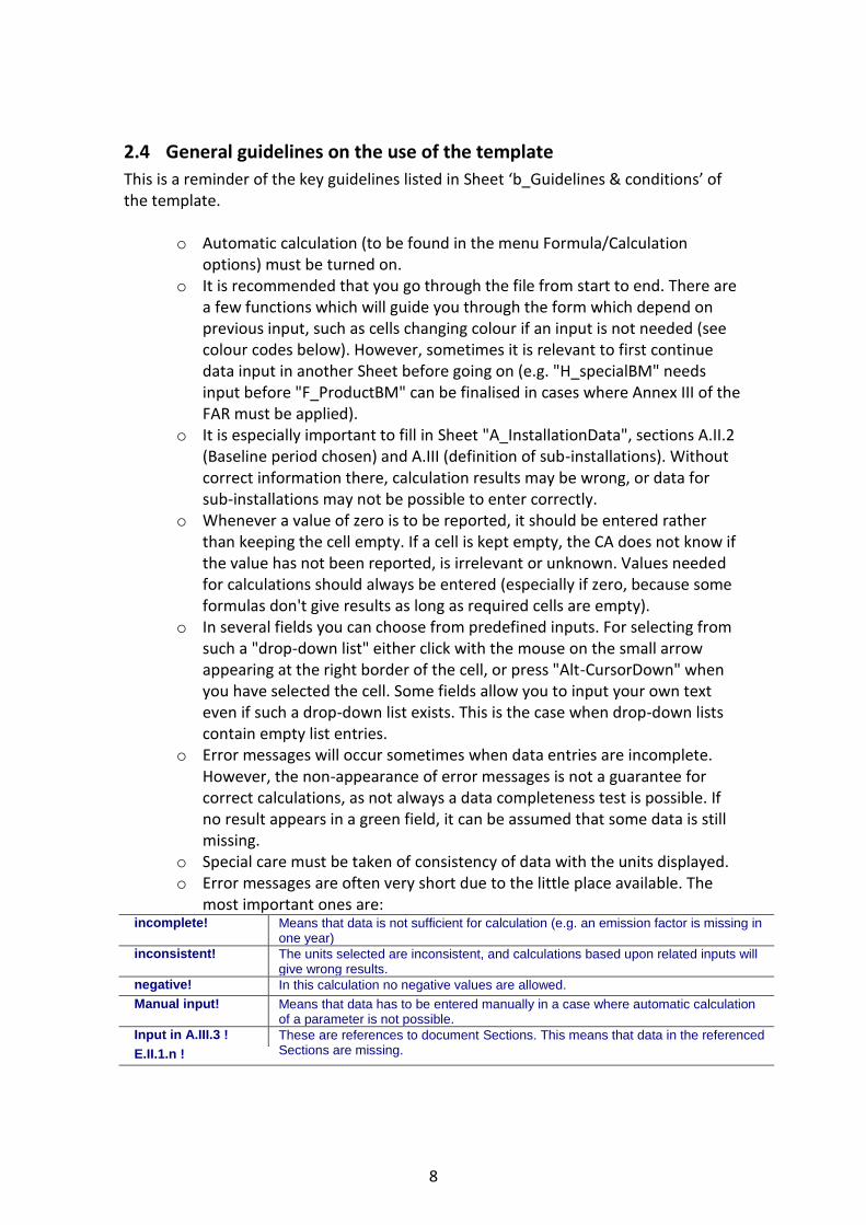
o Special care must be taken of consistency of data with the units displayed. o Error messages are often very short due to the little place available. The
most important ones are: incomplete! Means that data is not sufficient for calculation (e.g. an emission factor is missing in
one year)
inconsistent! The units selected are inconsistent, and calculations based upon related inputs will give wrong results.
negative! In this calculation no negative values are allowed.
Manual input! Means that data has to be entered manually in a case where automatic calculation of a parameter is not possible.
Input in A.III.3 ! These are references to document Sections. This means that data in the referenced Sections are missing. E.II.1.n !

9
o Colour codes and fonts: Black bold text: This is text describing the input required.
Smaller italic text: This text gives further explanations.
Yellow fields indicate mandatory inputs. However, if the topic is not relevant for the installation, no input is required.
Light yellow fields indicate that an input is optional.
Green fields show automatically calculated results. Red text indicates error messages (missing data etc).
Shaded fields indicate that an input in another field makes the input here irrelevant.
Grey shaded areas should be filled by Member States before publishing customized version of the template.
Light grey areas are dedicated for navigation and hyperlinks.
o Navigation panels on top of each Sheet provide hyperlinks for quick jumps to
individual input sections. The first line ("Table of contents", "Previous Sheet", "next Sheet", "Summary") and the points "Top of Sheet" and "End of Sheet" are the same for all Sheets. Depending on the Sheet, further menu items are added. If the background colour of one of the hyperlink areas turns red, this indicates that data is missing in the related section (not in all Sheets).
o This template has been locked against data entry except for yellow fields. However, for transparency reasons, no password has been set. This allows for complete viewing of all formulae. When using this file for data entry, it is recommended to keep the protection in force. The Sheets should only be unprotected for checking the validity of formulae. It is recommended to do this in a separate file.
o In order to protect formulae against unintended modifications, which usually lead to wrong and misleading results, it is of utmost importance NOT TO USE the CUT & PASTE. If you want to move data, first COPY and PASTE them, and thereafter delete the unwanted data in the old (wrong) place.
o Data fields have not been optimized for numerical and other formats. However, Sheet protection has been limited so as to allow you to use your own formats. In particular, you may decide about the number of decimal places displayed. The number of places is in principle independent from the precision of calculation. In principle the option "Precision as displayed" of MS Excel should be deactivated. For more details, consult MS Excel's "Help" function on this topic.

10
3 MS-specific parameters in NIMs baseline data template
This section is only relevant for Member states that use the NIMs baseline data template provided by the EC.
MSconst_RequirePermitInfo TRUE
MSconst_RequireArt27Info TRUE
MSconst_RequireArt27aInfo TRUE
MSconst_AllowInstEmmisionTotals FALSE
MSconst_RequirePermitInfo: If set to TRUE, the complete section A.I.1.g (Information on the Greenhouse gas emissions permit) becomes optional as indicated by the relevant colour change. MSconst_RequireArt27Info: If set to TRUE, entries in section A.I.4.d will become optional as indicated by the relevant colour change. MSconst_RequireArt27aInfo: If set to TRUE, entries in section A.I.4.e will become optional as indicated by the relevant colour change. “MSconst AllowInstEmissionTotals”: Member States can decide to allow operators to only declare total emissions at installation level. In order to do this, the parameter “MSconst AllowInstEmissionTotals” should be set to TRUE (this parameter is by default set to False). If this parameter is set to True, all the source stream related inputs are shown as optional, while the fields in D.I.2 change from “forbidden” to mandatory. In other words, operators no longer need to provide data for each source stream, but can enter totals only. If this parameter is set to False (default) completion of all five Sheets B+C is mandatory for each source stream and emission source.

11
4 Process of data collection for operators
This Chapter provides guidelines for operators on steps to take before submitting a complete NIMs baseline data template, the corresponding monitoring methodology plan and the verification report.
Good practice Description
Before receiving the NIMs baseline data template
Become familiar with the allocation rules
The data collection cannot be completed unless the operator knows how the allocation rules apply to his/her installation. The operator should therefore become familiar with the allocation rules.
Organise independent verification
Operators should contract an independent and accredited verifier, in line with the Accreditation and Verification Regulation, so that the completed NIMs baseline data template and the corresponding monitoring methodology plan can be verified. Especially for complex installations, it is advisable to foresee a two-step approach for verification, including a preliminary step only aimed at checking the correctness of the split into sub-installations of the installation.
After receiving NIMs baseline data template, before submission
Become familiar with the NIMs baseline data template and identify relevant Sections
Have first estimations about number of sub-installations, identify which product benchmarks are applicable, …
Make internal planning
Organise internally so that submission of NIMs baseline data template to CA will be in time, consider sufficient time for verification
Organise internal meeting(s) with relevant operators / technical experts
Operators may organise internal meetings with relevant operators and / or technical experts to discuss the availability and quality of data. Collect data sources of best available data.
Organise meeting(s) with technically connected installations (if relevant)
If an installation has relevant technical connections, it is recommended to align data of ingoing and outgoing streams (heat, waste gases, CO2) with the technically connected installation.
Ask for clarification if needed
If certain points are unclear, operators should ask their national CA for clarification.

12
5 Process of filling in the template
The next chapters of this Guidance Document mirror the structure of the Sheets of the NIMs baseline data template, including the following Sheets:
A “Installation Data” – General information on this report B+C “Annual Emissions Data” for the relevant Year D “Emissions” – Attribution of emissions E “Energy flows” – Data on energy input, measurable heat and electricity F “Product BM” – Sub-installation data relating to product benchmarks G “Fall-back” – Sub-installation data relating to fall-back sub-installations H “Special BM” – Special data for some product benchmarks I “MS specific” – Additional data requirements by the Member States J “Comments” – Comments and further information K “Summary” – Overview of most important data
The table below indicates which Sections of the template cover data relating to specific aspects.
Question Relevant Section in template
Determination of eligibility of free allocation
Is installation classified as “electricity generator”? A.II.1(a)
If yes, does it produce heat eligible for free allocation? A.II.1(d)
Determination of number of sub-installations
Is there a product benchmark sub-installation? A.III.1
Are there fall-back sub-installations (to be specified per type of sub-installation, including CL status)?
A.III.2
Determination of relevant technical connections
Which technical connections are relevant (name of connecting installation, type of connection, and flow direction)?
A.IV
Determination of direct emissions and energy flows
How many direct emissions occur at the installation? B+C (if detailed source stream data required) or D.I
How should direct emissions be attributed to sub-installations?
D.II
How are emissions split between heat and electricity in the case of a CHP?
D.III
How are process emissions calculated if waste gases are produced outside product benchmarks?
D.IV
How much energy input from fuels is there at the E.I.1(a)

13
installation?
How are fuels used attributed to sub-installations? E.I.1(c)
What is the heat balance of the installation? E.II
What is the waste gas balance of the installation? E.III
What is the electricity balance of the installation? E.IV
Determination of HAL product benchmarks
What is HAL of relevant product benchmarks? F and H in case of special product benchmarks
Determination of HAL fall-back sub-installations
HAL heat benchmark sub-installation(s) G.I.1 and G.I.2
HAL district heating sub-installation G.I.3
HAL fuel benchmark sub-installation(s) G.I.4 and G.I.5
HAL process emissions sub-installation(s) G.I.6 and G.I.7
14
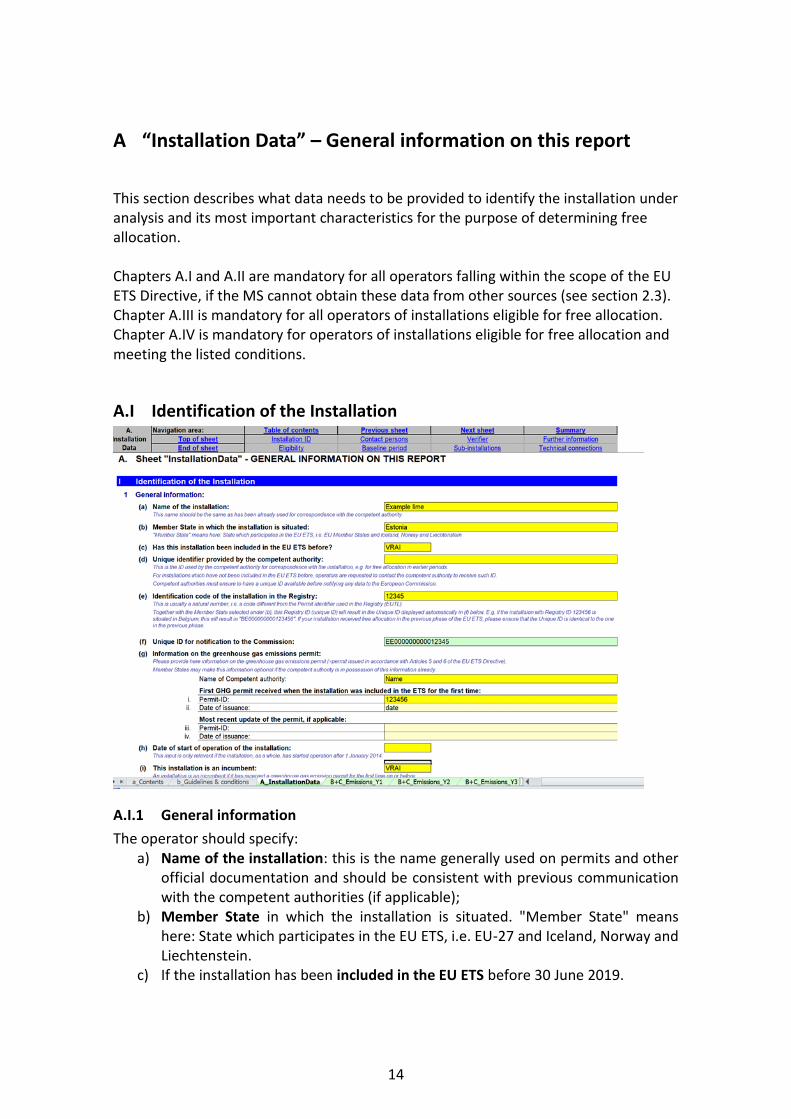
A “Installation Data” – General information on this report
This section describes what data needs to be provided to identify the installation under analysis and its most important characteristics for the purpose of determining free allocation. Chapters A.I and A.II are mandatory for all operators falling within the scope of the EU ETS Directive, if the MS cannot obtain these data from other sources (see section 2.3). Chapter A.III is mandatory for all operators of installations eligible for free allocation. Chapter A.IV is mandatory for operators of installations eligible for free allocation and meeting the listed conditions.
A.I Identification of the Installation
A.I.1 General information
The operator should specify: a) Name of the installation: this is the name generally used on permits and other
official documentation and should be consistent with previous communication with the competent authorities (if applicable);
b) Member State in which the installation is situated. "Member State" means here: State which participates in the EU ETS, i.e. EU-27 and Iceland, Norway and Liechtenstein.
c) If the installation has been included in the EU ETS before 30 June 2019.

15
d) Unique identifier code: this is usually the ID code used for the Phase 3 NIMs or any other ID issued by the competent authorities in accordance with Art 5 and 6 of the EU ETS Directive. For installations which have not been included in the EU ETS before, operators are requested to contact the competent authority to receive such ID. Competent authorities must ensure to have a unique ID available before notifying any data to the European Commission.
e) Identification code of the Installation in the Registry. This is usually a natural number, i.e. a code different from the Permit identifier used in the Registry, usually known as the installation ID. Together with the Member State selected under (b), this Registry ID (unique ID) will result in the Unique ID displayed automatically in (f) below. If your installation received free allocation in the previous phase of the EU ETS, please ensure that the Unique ID is identical to the one in the previous phase.
f) Unique ID for notification to the Commission, this is automatically derived and is an ID to be used with correspondence with the Commission;
g) Permit information: here the operator should fill in the name of the competent authority responsible for handling the permit of that installation, the permit ID and the date of issuance when the installation was first included in the EU ETS, as well as the most recent updated permit ID and date of issuance if applicable (i.e. re-issue dates and IDs). Member States may make this information optional if the competent authority is in possession of this information already.
h) Date of start of operation of the installation. This input is only relevant if the installation has started operation after 1 January 2014. If this date is left blank, it will be assumed that the date of start of operation was before 1 January 2014.
i) If the installation is an incumbent or a new entrant. A new entrant is an installation that has received a greenhouse gas emission permit for the first time after the 30 June 2019, or 30 June 2024, respectively. See Guidance Document 7 on new entrants and closures for more information on definitions of incumbents and new entrants. See also Guidance Document 2 on allocation approaches.
j) Operator data: name, address and phone numbers. The operator is the person who operates or controls an installation or to whom decisive economic power over the technical functioning of the installation has been delegated.
k) Installation address
A.I.2 Contact persons
The operator should specify the contact details of the person(s) responsible for completing or overseeing this report in case clarifications or communication is needed, In particular: name, address, email and telephone number should be reported.
A.I.3 Verifier engaged for this baseline data report
The operator should specify: a) The details of the verification company, in particular: company name, address
and country

16
b) The person who carried out (or project managed) the verification, in particular: name, e-mail address and telephone number
c) Information about the verifier’s accreditation, in particular the Member States in which it is allowed to operate in and the registration number issued by the Accreditation body. The availability of such registration information may depend on the administering Member State's practice of accreditation / permitting of verifiers. In case the Member State does not use accreditation but another way of recognising verifiers, the relevant information should be entered below as if it were accreditation.
A.I.4 Further installation data
The objective of this section is to further understand the activities carried out in the installation being assessed and to identify installations that may be opted-out of the EU ETS.
The operator is requested to specify:
a) The activities carried out at the installation as defined in Annex I of the EU ETS Directive. If activities other than 'combustion of fuels' are carried out, then it is not necessary to indicate activity 'combustion of fuels'. This specific activity is only relevant in case no other annex 1 activity is carried out by the installation. If several annex I activities are applicable, they should be listed starting with the activity causing the highest direct emissions, to the extent feasible.
b) Activity code according to the NACE classification under which the operator reported value added for structural business statistics. NACE rev 2.0 (used for the year 2010), at 4-digit level, should be specified. The list can be found here: http://ec.europa.eu/eurostat/ramon/nomenclatures/index.cfm?TargetUrl=LST_CLS_DLD&StrNom=NACE_REV2&StrLanguageCode=EN&StrLayoutCode=HIERARCHIC
In case of doubt, the operator is requested to contact the relevant national
17
statistics office. The NACE codes should be entered in the format of 4 digits with no dots or other delimiters in between.
c) The EPRTR4 identifier, optional and if applicable. This information is useful for the competent authorities for consistency checks and alignment of environmental information sources (i.e. national GHG inventories).
d) and e) Whether the installation is eligible for exclusion pursuant to Articles 27 or 27a of the EU ETS Directive. According to article 27(1) of the Directive, the following types of installations may be excluded from the EU ETS if they undertake equivalent measures: - installations that have reported less than 25,000 tonne of CO2 equivalent and, where they carry out combustion activities, have a rated thermal input below 35MW, excluding emissions from biomass, in each of the last three years; - installations which are hospitals. According to article 27a of the Directive, the following types of installations may be excluded from the EU ETS: - installations which have reported to the competent authority emissions of less than 2,500 tonnes of CO2 equivalent, excluding emissions from biomass, in each of the last three years; - units kept in reserve or as backup which did not operate more than 300 hours per year in each of the three years. The last three years to take into consideration for these exclusions are: - years 2016 to 2018 for the data collection in 2019; - years 2021 to 2023 for the data collection in 2024 For guidance on how to determine the total thermal rated input of an installation, see Annex I to the EU ETS Directive and “Guidance on Interpretation of Annex I of the EU ETS Directive (excl. aviation activities)”published by the Commission on XX. f) The annual emissions from the three previous years are automatically taken
from Sheet D of the tool for plausibility checks on the previous question. Nothing needs to be entered manually here.
g) Whether the installation has been opted-in. This should be indicated as True if the installation does not carry out at least one Annex I activity of the EU ETS Directive but has been unilaterally included by the Member State pursuant to Article 24 of the Directive.
4 EPRTR means European Pollutant Release and Transfer Register.

18
A.II Information on this baseline data report
A.II.1 Eligibility for free allocation
This section aims at understanding if the installation is eligible for free allocation or not. For more information on the eligibility criteria please refer to section 4 of Guidance Document 1 on general guidance. This section is mandatory for all installations, applying for free allocation or not (unless the CA prescribes otherwise). The operator should specify:
a) If the installation is an electricity generator pursuant to Article 3(u) of the EU ETS Directive.5 Article 3(u) of the EU ETS Directive defines an electricity generator as “an installation that on or after 1 January 2005, has produced electricity for sale to third parties, and in which no activity listed in Annex I [of the EU ETS Directive] is carried out than the combustion of fuels. See “Guidance paper to identify electricity generators” published by the Commission on 18 March 2010.
b) If it is an installation for the capture or transport of CO2, or if it is a CO2 storage site.
c) Whether the installation is considered to be covered by Article 10a(3) of the EU ETS Directive. This will be automatically deducted from the previous two answers (if one of them is True, this will be True as well). This will impact the application of the linear factor referred to in Article 10a(4) of the Directive. This factor is applied to allocations of installations covered by Article 10a(3) of the
5 Installations have to be classified either as electricity generator or non-electricity generators. The “Guidance paper to identify electricity generators” of March 18 2010 is to be used for this purpose.
19
Directive, except for any year in which those allocations are adjusted in a uniform manner pursuant to Article 10a(5) of the Directive (see also Article 16(8) of the FAR).
d) Whether the installation produces energy for purposes other than electricity production, e.g. qualifies for free allocation based on a fall-back approach (see section G of this guidance).
If the answer to (a) or (b) is positive and the answer to (d) is negative, then the installation is not eligible for free allocation under Article 10a of the Directive. For installations that are not eligible, the rest of this document is in principle not relevant, only the completion of this Sheet (Sheet A on “installation data”) is mandatory. It is however recommended to provide the data requested in section E ‘Data on energy input, measurable heat and electricity’ to ascertain that the status of the “electricity producer” is appropriately defined. If the answer to (a) or (b) is positive and the answer to (d) is positive as well, then the installation may be eligible for free allocation (in case heat is delivered to non ETS entities or installations). The operator should further answer either (e) or (f), which will also lead to answer (g):
e) Confirm the non-eligibility of the installation for free allocation under Article 10a of the EU ETS Directive in case the answer to (a) or (b) is positive and the answer to question (d) is negative.
f) Confirm the eligibility of the installation for free allocation under Article 10a of the EU ETS Directive in case the answers to both (a) and (b) are negative, or if answer to (d) is positive.
g) Confirm that the data contained in this file may be used by the competent authority for determining the free allocation pursuant to Article 10a of the EU ETS Directive. Furthermore these data will be notified to the European Commission in part or as a whole, if requested so, for the purpose of scrutinising the national implementation measures pursuant to Article 11(1) of the EU ETS Directive. The consent is necessary to make the submission of data complete. If the operator confirms point (e) or (f), it is automatically assumed that this also confirms consent to use data contained in this file, and therefore answer to (g) is automatic.
Important note The answers to the questions in this section have no impact on the possible free allocation under Article 10c of the EU ETS Directive which is about transitional free allocation for the modernisation of electricity production.
A.II.2 Baseline period chosen
In this section the baseline period is chosen and the years in which the installation was operating are indicated. The operator should:

20
a) Select the relevant baseline period for the report, in line with Article 21(4) of the FAR: for the period 2021 to 2025, the relevant baseline period to choose is 2014-2018 (this is the baseline period indicated by default by the template); for the period 2026 to 2030, the relevant baseline period is 2019-2023.
b) Specify the years in which the installation was operating for at least one day in that calendar year. A calendar year is the period between 1 January and 31 December of the same year. Please indicate True or False for each year. E.g. assuming the installation started on any day in 2015, the answer for 2014 would be False, and the answer for the years 2015 to 2018 would be True.
A.III List of sub-installations
This section describes what data should be reported to identify the sub-installations present in the installation. This section is mandatory for all installations that are eligible for free allocation. For more information on the eligibility criteria please refer to section 4 of Guidance Document 1 on general guidance. It is essential that all sub-installations in this section are entered correctly, as this will impact all further input relating to sub-installations. The start of normal operation needs to be reported only if it occurred after 1 January 2014, or 1 January 2019, for the respective baseline period. This will impact for each sub-installation the years to be taken into account for the determination of the HAL. If the start was on or before 1 January, entries are not mandatory.6
6 If the 95% rule (also called “de-minimis” rule) is used, then the sub-installation covering less than 5% of inputs, outputs and emissions does not need to be included in the list of sub-installations.

21
More details on how to derive the sub-installations is given in Guidance Document 2 on allocation approaches.
A.III.1 Product benchmark sub-installations
The operator should specify all product benchmark sub-installations covered by the installation’s permit. For each type of product, only one sub-installation may be chosen, and each sub-installation name may occur only once. Products that are covered by the same product definition in the FAR are aggregated in the same sub-installation and have the same product benchmark. In the NIMs baseline data template the operator can select the benchmark products in the drop down menu. For an overview of product benchmarks and associated product definitions and system boundaries see Annex I of the FAR and for more guidance on the appropriate product definition see Guidance Document 9 on sector specific guidance7 The operator should also determine for each sub-installation whether or not it is deemed to be exposed to a significant risk of carbon leakage. In the NIMs baseline data template, the carbon leakage exposure status will be determined automatically based on Commission Decision XXX. For an overview of carbon leakage exposure statuses, see Annex I of the FAR or Guidance Document 9 on sector specific guidance. In addition, in the second yellow column, the operator should provide the date of start of normal operation8 for each sub-installation, in line with Article 2(12) of the FAR. This will help identify which years are to be taken into account for the determination of the historical activity level, in line with Article 15(7) in sheets F and G. It will in particular help identify if a sub-installation has operated less than two calendar years during the baseline period, in which case specific provisions will apply for the calculation of its historical activity levels. For more information on sub-installations that haven’t been operating during the full baseline period, see section 6.2 of Guidance Document 2 on allocation approaches.
A.III.2 Sub-installations with fall-back approaches
The operator should specify which fall-back sub-installations are relevant for the installation, and which are not (no yellow fields should remain empty). Each installation can have a maximum of seven sub-installations covered by fall-back approaches: for each type of fall-back approach (heat benchmark, fuel benchmark and process emissions), a maximum of two sub-installations may exist, one deemed to be exposed to a significant risk of carbon leakage, and the other non-exposed. An exception to this rule is the possible presence of a third sub-installation for measurable
7 Note that in some cases separate sub-installations can cover the same physical units, for example two benchmarked products can be manufactured from the same production line. This is not an issue as long as the activity levels for each product are well defined. For a practical example please see to Guidance Document 2 on allocation approaches. 8 For guidance on the definition of start of normal operation, see Guidance Document 2 on allocation methodologies.
22
heat, corresponding to the delivery of heat for the purpose of district heating. See Guidance Document 1 on general guidance for further input on sub-installations covered by fall-back approaches. See also Guidance Document 5 on Monitoring and Reporting in relation to the FAR for more information on data to be provided to justify the use of a district heating sub-installation. In addition, in the second yellow column, the operator should provide the date of start of normal operation9 for each sub-installation, in line with Article 2(12) of the FAR. This will help identify which years are to be taken into account for the determination of the historical activity level, in line with Article 15(7) in sheets F and G. . It will in particular help identify if a sub-installation has operated less than two calendar years during the baseline period, in which case specific provisions will apply for the calculation of its historical activity levels. For more information on sub-installations that haven’t been operating during the full baseline period, see section 6.2 of Guidance Document 2 on allocation approaches. In line with Article 10(3) of the FAR, an exemption from the distinction between the “Carbon Leakage” and the “non-Carbon Leakage” is possible for reporting purposes, if at least 95% of inputs, outputs and emissions belong to one of the statuses. For more information on this so-called “de-minimis rule”, see Guidance Document 2 on allocation approaches at installation level, and Guidance Document 5 on Monitoring and Reporting.
A.IV List of technical connections
This section is only relevant in the following cases: - installations where measurable heat, waste gases, intermediate products
covered by product benchmarks or “transferred CO2” as defined by the Monitoring and Reporting Regulation are transferred to or from another ETS installation or non-ETS entity;
- installations where heat is consumed that was produced by a nitric acid installation, even if the nitric acid production is part of the same installation.
The data requested in this section is particularly relevant to ensure consistency of the data provided and to avoid double counting of allocation data. The information on this section will be particularly important for the treatment of cross boundary heat flows and waste gases. For more information on these two issues see Guidance Document 6 on cross boundary heat flows and Guidance Document 8 on waste gases and process emissions sub-installations.
9 For guidance on the definition of start of normal operation, see Guidance Document 2 on allocation methodologies.
23
The operator should specify: a) Information relevant for identifying technical connections to the installation, in
particular: - Name of the ETS installation or non-ETS entity linked to the installation
assessed. In case heat is consumed that was produced as a result of nitric acid production within the same installation, then the name of the installation itself should be provided in the NIMs baseline data template.
- Type of entity: “Installation covered by ETS”, “Installation outside ETS”, “Installation producing Nitric Acid”, or “Heat distribution network”. In the case of a heat distribution network, this information should be provided, regardless of whether the entity is part of the ETS or not. The NIMs baseline data template facilitates the selection by providing a drop-down menu.
- Type of connection, i.e. is the connection due to an exchange of measurable heat, waste gas, transferred CO2, or intermediate products covered by product benchmarks10?
- Flow direction, i.e. is it net import or net export, considering it from the perspective of the installation to which this report refers (‘Import’ to this installation, or ‘Export’ from this installation)?
b) Further information regarding those connected installations, if relevant: - The CITL installation ID; Installation ID is mandatory if the connected
installation is covered by the EU ETS, and if it has already been covered by the EU ETS before 30.6.2019 for the first allocation period, and before 30 June 2024 for the second allocation period.
- The name and contact details of the operator at that installation so that any communication is facilitated. For entities not covered by the EU ETS, the contact details are mandatory but the Registry ID is not required.
10 In line with Sections 1.6 and 3.1(l) of Annex IV of the FAR.

24
B+C “Annual Emissions Data” for the relevant Year
This section aims to provide guidance on the collection of data relating to emission source streams, originating from combustion and/or process emissions. A separate worksheet is prepared for each year of the baseline period. Therefore for the first baseline period, worksheet “B+C Emissions Y1” refers to year 2014, worksheet “B+C Emissions Y2” refers to year 2015, and so on until “B+C Emissions Y5” which refers to year 2018. For the second baseline period, these Sheets refer respectively to years 2019 to 2023. Chapter B+C.I indicates whether providing data in this section is mandatory or not (see section on MS-specific parameters).
B+C.I General Guidance for source stream data
The elements in this section are valid for all sections in Sheets “B+C Emissions Yx”. Member States may allow operators to only report totals for the whole installation in section D.I. If this is the case, the “Member State requires detailed source stream data generally to be reported mandatorily” is indicated as False in this section, and entering data in these Sheets is optional (it is then possible to only report annual total emissions in section D.I).
B+C.II Source streams and emission sources
The elements in this section are valid for all sections in Sheets “B+C Emissions Yx”. In line with what is indicated in the previous paragraph, data is only required in this workSheet if True is indicated in B+C.I.

25
The data has been structured to mirror the Sheet “accounting” in the Annual Emissions Report (AER) template provided by the Commission. It is therefore possible to copy data for each table from the AER and paste it into this report without further entries. If the Commission’s template is not used in the relevant Member State, or if the operator prefers to enter data manually, examples are provided at the beginning of each table to help the operator. The relevant guidance in the Commission’s AER template might still be useful for further clarification, if needed. Important note Please note that no calculations are made in these Sheets. Therefore the totals provided in columns AU to AY need to be entered correctly as these data will be further used in the template.
26
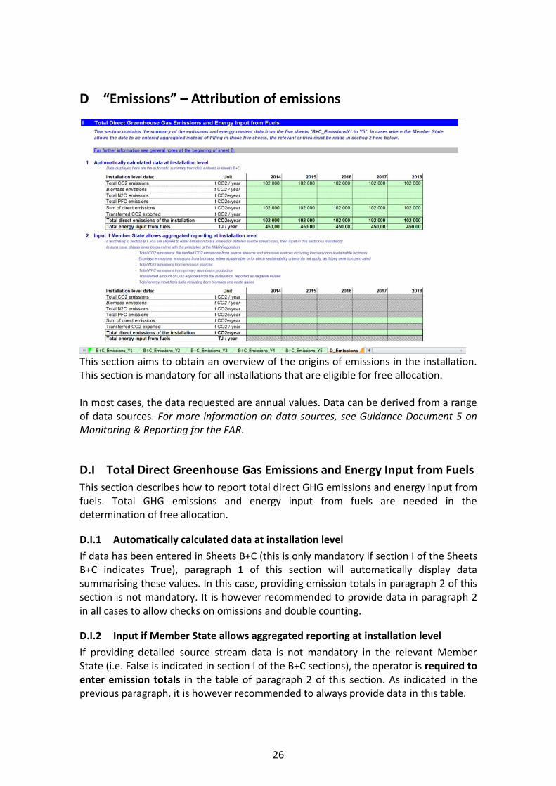
D “Emissions” – Attribution of emissions
This section aims to obtain an overview of the origins of emissions in the installation. This section is mandatory for all installations that are eligible for free allocation. In most cases, the data requested are annual values. Data can be derived from a range of data sources. For more information on data sources, see Guidance Document 5 on Monitoring & Reporting for the FAR.
D.I Total Direct Greenhouse Gas Emissions and Energy Input from Fuels
This section describes how to report total direct GHG emissions and energy input from fuels. Total GHG emissions and energy input from fuels are needed in the determination of free allocation.
D.I.1 Automatically calculated data at installation level
If data has been entered in Sheets B+C (this is only mandatory if section I of the Sheets B+C indicates True), paragraph 1 of this section will automatically display data summarising these values. In this case, providing emission totals in paragraph 2 of this section is not mandatory. It is however recommended to provide data in paragraph 2 in all cases to allow checks on omissions and double counting.
D.I.2 Input if Member State allows aggregated reporting at installation level
If providing detailed source stream data is not mandatory in the relevant Member State (i.e. False is indicated in section I of the B+C sections), the operator is required to enter emission totals in the table of paragraph 2 of this section. As indicated in the previous paragraph, it is however recommended to always provide data in this table.
27
The operators should specify the following data in the table of paragraph 2 for each year of the baseline period:
o Total CO2 emissions from fossil and non-sustainable biogenic origin in tonnes of CO2 per year11;
o Biomass emissions, either from sustainable biomass, or from biomass for which sustainability criteria do not apply, in tonnes of CO2 per year12;
o Total N2O emissions in tonnes of CO2 equivalent per year; o Total PFC emissions in tonnes of CO2 equivalent per year; o The sum of direct GHG emissions in tonnes of CO2 equivalent per year (i.e. the
sum of the fossil emissions specified above) is calculated automatically by the tool;
o Amount of transferred CO2 exported from the installation in tonnes of CO2 per year. Figures should be entered as negative values;
o Total direct emissions of the installation in tonnes of CO2 equivalent per year, taking into account the transferred CO2 are automatically calculated by the tool;
o Total energy input from fuels in TJ per year, including from biomass and waste gases. This value should reflect the total net energy input if any of the source streams of the installation is evaluated on the basis of a mass balance.
D.I.3 Result of installation level data for use in Sheets “D_Emission” and “E_EnergyFlows”
In this paragraph, the NIMs baseline data template automatically selects the data to be used further in the tool. If data is displayed both in paragraph 1 and paragraph 2, and if there are differences between the two, data provided in paragraph 2 will be used as no completeness checks can be performed on data provided in Sheets B+C. The conflicting values will be highlighted with red figures in the table of paragraph 3. It is the responsibility of the operator to review and correct the conflicting data.
D.II Attribution of emissions to sub-installations
For the purpose of allocation operators are required to attribute the total emissions to one or more sub-installation(s). In this section, data is automatically calculated based on data provided in WorkSheets F and G.
D.II.1 Total emissions at installation level
This table provides the total direct annual emissions at installation level in tonnes of CO2 equivalent per year, taken from paragraph D.I.3. This is the amount that will then be split between the different sub-installations.
11 This figure should be consistent with the annual emissions reported under the MRR, before taking into account any transferred CO2. 12 These are biomass emissions as if they were non-zero rated.

28
D.II.2 Attribution to sub-installations
The attribution of emissions to sub-installations has to be done in sheets F and G for each sub-installation. A link to the summary sheet (section K.III.2) is provided in this section to have direct access to the summary table of attributed emissions that can be found there.
D.III Cogeneration tool
This section provides a tool for assigning fuels and emissions of CHPs for the purpose of updating the benchmark values pursuant to chapter 8 of Annex VII of the FAR. Operators that have no CHP at their installation should answer False to the question “Are combined heat and power (CHP) units relevant?”, and no data will then need to be entered in this section.
Operators that have one or more CHPs at their installation should answer True to the question “Are combined heat and power (CHP) units relevant?”. In this case, providing the data in this section is mandatory for all of the CHPs.

29
In cases when heat imported from another installation has been produced by a CHP, this tool may be relevant as well if sufficient information on the data is available from the supplier. Periods during which the CHP is operated in heat-only or electricity-only generation mode (i.e. producing respectively 100% heat or 100% electricity) should be excluded from the data provided in the cogeneration tool. In this case, the assignment of fuels and emissions should be calculated separately as would be done for e.g. stand-alone heat producing boilers, in accordance with the provisions in sections 10.1.2 and 10.1.3 of Annex VII of the FAR.
D.III.1 Tool for calculating the emissions attributable to heat production in combined heat and power units (CHP)
The tool provided in this paragraph is for one CHP. If a second CHP is relevant on-site or for any measurable heat imported, data relating to the second CHP should be provided in paragraph D.III.2. If more CHPs are relevant, a separate template might be used to provide relevant information.

30
The operator should provide the following data, where relevant:
(a) Total amount of fuel input into CHP units: the annual fuel input into the CHP unit should be provided in TJ per year;
(b) Heat output from CHP: the total amount of heat produced each year by the CHP unit should be provided in TJ per year;
(c) Electricity output from CHP: the total amount of electricity (or mechanical energy, where applicable) produced each year by the CHP unit should be provided in MWh per year;
(d) Total emissions from CHP: the amount of emissions from fuel input to CHP should be provided, as well as the amount of emissions from flue gas cleaning, both in tonnes of CO2 per year. The total amount of emissions in tonnes of CO2 per year is calculated automatically by the tool.
(e) Default efficiencies: if the operator can provide evidence to the satisfaction of the competent authority that the determination of the efficiencies of heat and electricity is technically not feasible or would incur unreasonable costs, values based on technical documentation (design values) of the installation should be used. If these are also not available, then it is possible to leave tables (a) to (c) above empty, and enter only data relating to total emissions from CHP in table (d). In this case, these default efficiencies (55% for heat and 25% for electricity) will be used in the calculations;
(f) Efficiencies for heat and electricity: these dimensionless values are calculated from inputs (a) to (c) above (see (e) if inputs (a) to (c) are not available);
(g) Reference efficiencies: the included values are the reference efficiency for heat production in a stand-alone boiler, and the reference efficiency of electricity production without cogeneration, based on the use of natural gas. The operator should update these values with the appropriate fuel-specific values from Annexes I and II of the Commission Delegated Regulation (EU) 2015/2402,

31
without application of the correction factors for climatic conditions in Annex III and avoided grid losses in Annex IV of this Regulation (the Regulation can be downloaded via https://eur-lex.europa.eu/eli/reg_del/2015/2402/oj);
(h) Emissions attributable to heat production from CHP: the emissions attributable to the heat output, indicated in tonnes of CO2 per year, as well as the heat emission factor in tonnes of CO2 per TJ are automatically calculated by the tool, based on the data provided in this tool. These results should be entered in section F.I.1(k) (“Measurable heat import to and export from this sub-installation”) or in Sheet G of the NIMs baseline data template for the attributable emissions to the appropriate sub-installation. For example, this may include attributable emissions to be taken into account for the total direct emissions, or use of the emission factor for any measurable heat imported;
(i) Fuel input attributable to heat and electricity production: the fuel input for heat and the fuel input for electricity, indicated in TJ per year, are automatically calculated by the tool based on the data provided in this tool. These results should be entered in relevant sections in sheets E, F and G1(c).
D.III.2 Tool for calculating the emissions attributable to heat production in combined heat and power units (CHP)
This tool is to be filled in if the installation includes two CHPs. In this case this tool is for the second CHP and should be filled in according to instructions provided in paragraph D.III.1. If more CHPs are relevant, a separate template might be used to provide relevant information.
D.IV Waste gas tool
The objective of this section is to help operators calculate the emissions that should be attributed to process emissions sub-installations in case of waste gas production outside the boundaries of a product benchmark. Data should be provided in this waste gas tool if the following two conditions are met:
- The waste gases are produced outside the boundaries of a product benchmark (within the operator’s installation or within an installation from which the operator’s installation is importing the waste gases);
- The installation consumes such waste gases. (It does not matter whether these waste gases were produced in the same ETS installation that consumes the waste gases.) See Guidance Document 8 on waste gases and process emissions sub-installations for a definition of production processes that produce waste gases outside the boundaries of a product benchmark.
If both conditions are met, this section is relevant, True should be answered to the first question of this section, and data should be provided in this waste gas tool.

32
According to the definition in Article 2(10), combusted waste gases are considered to be process emissions if they are produced outside the boundaries of a product benchmark and only to the extent that they exceed the emissions from the combustion of an amount of natural gas with an equivalent amount of technically useable energy content. For more information on allocation in case of the production and consumption of waste gases please refer to Guidance Document 8 on waste gases and process emission sub-installations. The operator should specify the following data separately for a process emissions sub-installation deemed to be exposed to a significant risk of carbon leakage and not deemed to be exposed to a significant risk of carbon leakage. Because both possible sub-installations can be concerned in one installation, or because different waste gases can occur, the "waste gas tool" exists twofold in the NIMs baseline data template. The data for the two sub-installations together should add up to the totals for the installation.
D.IV.1 Tool for calculating the amount of process emissions if waste gases are produced outside product benchmarks
The operator should specify: a) The type of process emissions sub-installation concerned (exposed to carbon
leakage or non-exposed); b) Whether the installation consumes waste gases (i.e. select “relevant”) or not
(i.e. select “not relevant”); c) Type of waste gas. The operator should choose a name for the gas stream in
the first box, and describe the waste gas and the process that produces it in the second box. For example, the description can include the production process where the waste gas originated from, the composition of the gas (e.g. contents
33
of CO, CO2, NOx, SO2, etc.), or a description of the process where it is efficiently combusted. In case there are several waste gases streams, the operator should provide data for the different streams in separate files (in this case, the operator should provide separate files in which only this section is filled in for different streams).
d) Total amount of “uncorrected” process emissions in tonnes of CO2 equivalent per year. In line with Article 2(10) of the FAR, when calculating allocation for waste gases, an amount of CO2 equivalent to natural gas used for the “technically usable energy content” needs to be subtracted from the total process emissions. The amount of process emissions before this subtraction is referred to as “uncorrected process emissions” in this tool and reflects all types of process emissions (referred to as types a, b and c in Guidance Document 8);
e) Estimation of emissions from the combustion of the waste gases used or exported, in tonnes of CO2 equivalent per year, when combusted for other purposes than flaring (unless it is for safety flaring), taking into account the relevant carbon leakage status. This field is optional and is meant for cross checking. The values must be consistent with the amount of waste gases provided in point (f) below.
f) Amount of waste gas (in thousand Nm3 per year or in tonnes per year) produced outside of the product benchmark sub-installations and combusted for other purposes than flaring (only in case of safety flaring can the amount of flared waste gases for safety reasons be taken into account). The relevant carbon leakage status (as selected under point (b)) must be taken into account. The data can be entered either in tonnes per year, or in 1000 Nm3 per year; the NIMs baseline data template facilitates the selection of unit by providing a drop-down menu. The choice of unit must be consistent with the unit used for the NCV below (point (g)). It does not matter whether the waste gases were produced in the same ETS installation as the one consuming the waste gases or not.
g) Net calorific value (NCV) of the consumed waste gas, The net caloric value is the amount of heat released during the combustion of the fuel, minus the energy required to vaporise water produced during combustion. NCVs should be determined in compliance with Annex VI of the FAR. The NCV should be expressed in GJ per1000Nm3 or GJ per tonne depending on the unit chosen under point (f). The data collection automatically selects the proper unit based on the selection under (f).
h) Necessary assumptions: these include the reference efficiencies for the production of electricity using natural gas and using waste gas in %, as well as the emission factor for natural gas. See Guidance Document 8 on waste gases and process emission sub-installations for guidance on the reference efficiencies.
i) Emissions to be subtracted for taking into account the technically usable energy content. These amounts in tonnes of CO2 equivalent per year are automatically calculated based on the provided data. They correspond to the “consumer part” of the emissions, to be distinguished from the “producer part”

34
of the emissions; see Guidance Document 8 on waste gases and process emission sub-installations for additional guidance.
j) Process emissions calculated taking into account the correction for waste gases. This is the final result provided by the tool, in tonnes of CO2 per year. This amount is defined as the difference between the emissions specified under (d) and (i). The NIMs baseline data template automatically performs the calculation. The resulting data should be entered in section G of the tool for the relevant process emissions sub-installation. If the result is negative, it should be set to zero.
D.IV.2 Tool for calculating the amount of process emissions if waste gases are produced outside product benchmarks
This tool is to be filled in if the installation includes two process emissions sub-installations (one CL and one non-CL), both including waste gases, or if several types of waste gases are consumed within the installation. In this case this tool is for the second process emissions sub-installation or for the second type of waste gas, and should be filled in according to instructions provided in paragraph D.IV.1.
35
E “Energy Flows” – Data on energy input, measurable heat and electricity
E.I Energy input from fuels
This section describes how to report data relating to the attribution of fuel input to the different sub-installations. The free allocation to fuel benchmark sub-installations is directly based on the fuel input attributed in this section. In most cases, the data requested are annual values. Data can be derived from a range of data sources. See Guidance Document 5 on Monitoring & Reporting for the FAR for more guidance on this topic.
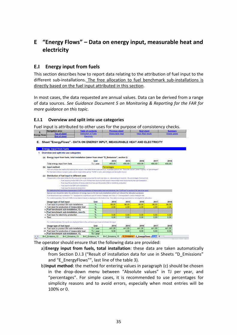
E.I.1 Overview and split into use categories
Fuel input is attributed to other uses for the purpose of consistency checks.
The operator should ensure that the following data are provided:
a) Energy input from fuels, total installation: these data are taken automatically from Section D.I.3 (“Result of installation data for use in Sheets “D_Emissions” and “E_EnergyFlows””, last line of the table 3).
b) Input method: the method for entering values in paragraph (c) should be chosen in the drop-down menu between “Absolute values” in TJ per year, and “percentages”. For simple cases, it is recommended to use percentages for simplicity reasons and to avoid errors, especially when most entries will be 100% or 0.

36
c) Indicate the fuel input attributed to different usage types of fuel input. These include: o Fuel input used within the boundaries of product benchmarks. See
Guidance Document 9 on sector-specific guidance for guidance on system boundaries of product benchmarks. The fuel input includes: - Fuel input to production processes in the installation covered by
product benchmarks. This excludes fuel input for to the production of measurable heat that is consumed by production processes covered by product benchmarks.
- Fuel input for the onsite production of measurable heat consumed by production processes in the installation covered by the product benchmark. Note that since only the fuel input to the installation is considered here, fuel input related to the production of imported heat should not be included.
Because heat import and export is not considered, the fuel input under this bullet may not completely conform to fuel input related to product benchmark sub-installation.
o Fuel input for the production of measurable heat outside the boundaries of product benchmarks. This should exclude fuel input related to electricity production. Note that since only the fuel input to the installation is considered here, fuel input related to the production of imported heat should not be included. Because heat import and export is not considered, the fuel input under this bullet may not completely conform to fuel input related to heat benchmark sub-installations. It should be noted that heat may be produced both for consumption within product benchmark sub-installations and outside product benchmark sub-installations (e.g. heat export, consumption of production processes not covered by product benchmarks, electricity production). If the heat is used within the boundaries of a product benchmark, then the share of fuel used to produce this amount of heat should be included in the share of fuel input to product benchmark sub-installations;
o Fuel input within the boundaries of a fuel benchmark sub-installation deemed to be exposed to a significant risk of carbon leakage (i.e. “Fuel benchmark sub-installation, CL”). See Guidance Document 2 on allocation approaches for guidance on which fuel is consumed within the boundaries of a fuel benchmark sub-installation. This excludes fuel input for the production of measurable heat and electricity. The fuel benchmark sub-installation covers the use of waste gases as fuel for the production of non-measurable heat. For waste gases that were produced outside the boundaries of a product benchmark sub-installation, this sub-installation also covers safety flaring (so no other flaring). If part of the carbon in the fuel leaves the product benchmark sub-installation as part of a waste gas, then the energy content of the share of the waste gas that originates from the fuel should be subtracted from the fuel input. See Guidance Document 8 on waste gases and process emission sub-installations for additional

37
guidance on this topic. It should be noted that a production process may be involved in the production of both products covered by a product benchmark and of products not covered by a product benchmark. In that case shares of the total fuel input related to that process should be attributed to product benchmark sub-installations on the one side and to heat production and fuel benchmark sub-installations on the other side.
o Fuel input within the boundaries of a fuel benchmark sub-installation not deemed to be exposed to a significant risk of carbon leakage (i.e. “Fuel benchmark sub-installation, non-CL”). The guidance for this sub-installation is identical as the guidance in the previous bullet.
o Fuel input for the production of electricity. o Fuel input used for other purposes. The NIMs baseline data template
automatically calculates this amount as ‘Rest’.
The units used are those chosen in paragraph (b); a second table is provided with the values displayed in the other unit (in % if TJ/year were chosen, in TJ/year if % were chosen), allowing for a control of the results by the operator. If fuel is used in a CHP, the results from the CHP tool in Section D.III.1(i) should be used here for measurable heat and electricity production. Extra care should be taken in the calculation of the values provided for the two fuel benchmarks sub-installations, as these will be used for allocation purposes. The sum of all the provided values should be equal to the total annual fuel input at installation level indicated in paragraph (a). This is checked in the last line of the table. Any rest of fuel that is indicated there refers to energy input which is not eligible for allocation. The attribution of fuel input to different uses should be made on a fair basis (such as shares of operating time or production volumes combined with specific fuel input related to different products). The operator should report in detail on the way that the attribution of fuel use was made. In case of uncertainty, the attribution should be biased such that more fuel input is attributed to the product benchmark sub-installation. In general, the attribution of fuel input as described in this Section should be consistent with the attribution of emissions to different uses as indicated in Section D.II.2 (only if that Section is relevant for the installation under consideration).
E.II Measurable heat
This Section describes how to report data related to heat production, consumption, import and export. The operator should first indicate whether this section is relevant, by answering the question “Are any measurable heat flows produced or consumed in, imported to or exported from this installation?”

38
If the answer to this question is “TRUE”, then the data included in this section should be provided13; if the answer to this question is “FALSE”, then the operator can move on to the next section. Note that this section will always be relevant if any of the heat benchmark or district heating sub-installations are selected to be relevant in section A.III.2. In such case, the indicator will be greyed out. See Guidance Document 5 on Monitoring & Reporting for the FAR for guidance on how to determine amounts of net measurable heat. All heat data refers to “net amount of measurable heat”, which is the heat content of the heat flow to the user from which the content of the return flow is subtracted. To calculate the amount of heat that is eligible for free allocation under a heat benchmark sub-installation, the operator should first obtain a complete balance of the measureable heat at the installation. The following distinctions should be made:
o For heat input: o “eligible” heat: net measurable heat is considered eligible if it is
produced by the installation or imported from another ETS installation.
o “non-eligible” heat: heat is considered non-eligible if it is imported from a non-ETS installation, or produced from a nitric acid sub-installation.
o For heat use: o “eligible” heat: net measurable heat is considered eligible if it is
used within the installation or exported to a non-ETS entity. o “non-eligible” heat: heat is considered non-eligible if it is consumed
for electricity production or exported to an ETS installation. The aim of this tool is to clearly identify the amounts of eligible and non-eligible heat, and to earmark each of them. For this the following hierarchy of approaches is proposed:
1. If the distinction between eligible and non-eligible heat is clear on site, because e.g. of separated heat grid connections or different steam pressures, the eligible and non-eligible heat amounts should be reported based on the real situation and measured values.
2. If this first approach is not feasible, all uses should be weighted based on the ratio of inputs (ETS input over total input).
In this tool, the operator should first ensure that the following data are specified, listing all heat inputs: a) Total net amount of measurable heat produced within the boundaries of the
installation in TJ per year. This includes the measurable heat production from all
13 Unless all heat produced is consumed exclusively within the system boundaries of a unique sub-installation with no import or export of heat. In this case only the detailed heat data do not need to be provided.
39
sources, e.g. CHP units, boilers, recovered heat, etc. See Guidance Document 6 on cross-boundary heat flows for additional guidance on the definition of measurable heat.
b) Net measurable heat imported from installations covered by the EU ETS (eligible for free allocation under the heat benchmark sub-installation), specified per ETS installation in TJ per year. The name of installations is to be selected from the drop-down list, which is based on the list of technical connections described in Section A.IV (“List of technical connections”). If the name of the connecting installation cannot be found, it should be in Section A.IV.
c) Net measurable heat imported from installations and entities not covered by the EU ETS (not eligible for free allocation under the heat benchmark sub-installation), specified per non-ETS entity in TJ per year. This should include heat produced from nitric acid sub-installations (in this case “Within installation” should be selected as name of installation, if the nitric acid production is part of this installation). The data entered in this table will be checked for double counting with deductions under product benchmark sub-installations (see Sheet F_ProductBM). The name of installations is to be selected from the drop-down list, which is based on the list of technical connections described in Section A.IV (“List of technical connections”). If the name of the connecting installation cannot be found, it should be in Section A.IV. The amount of heat included here should include the amount of net measurable heat produced from electricity indicated in section (d) here-after.
d) Net measurable heat produced from electricity in TJ per year (not eligible for free allocation under the heat benchmark sub-installation). This includes heat from any electric pumps, electric boilers, etc. This amount of heat is to be included in the total net measurable heat imported from installations and entities not covered by the EU ETS in (c) above.
e) Sum of measurable heat available in the installation in TJ per year. This is the sum of the amount of measurable heat produced (a), the net imported measurable heat from ETS installations (b) and non-ETS entities (c). The NIMs baseline data template automatically calculates this amount.
f) Ratio of “ETS heat” to “Total heat” in %. “ETS heat” is the sum of the measurable heat produced in the installation (a) and the measurable heat imported from other ETS installations (b). “Total heat” is the measurable heat specified under (e). The NIMs baseline data template automatically calculates this amount. This ratio is only needed in case it is not feasible to clearly earmark which shares of individual heat flows are produced within and outside the boundaries of ETS installations.
Next the operator needs to assess which part of the measurable heat is not eligible for free allocation under a heat benchmark sub-installation. See Guidance Document 2 on allocation approaches for guidance on this topic. The operator should therefore ensure that the following data, relating to heat not falling under heat benchmark sub-installations, are specified: g) Measurable heat consumed for electricity production within the installation (not
eligible for free allocation under the heat benchmark sub-installation). This includes:

40
i. Measurable heat used for electricity production in TJ per year. ii. Amount of this heat that is provided by non-ETS sources in TJ per year.
By default, the ratio determined under (f) is used to calculate this amount. The NIMs baseline data template automatically performs this calculation.
iii. If more precise information on the amount of heat from non-ETS sources is available (e.g. because steam from different sources can be distinguished due to different pressure levels), the values calculated in g.ii can be modified here in a manual override. If this amount exceeds the amount indicated in (c).iv, the available maximum value will be used for further calculation.
h) Measurable heat consumed for product benchmark sub-installations within the installation (not eligible for free allocation under the heat benchmark sub-installation), in TJ per year: the operator should check this amount for plausibility by comparing it to the total amount of heat from non-ETS sources in product benchmark sub-installations as requested in Section F.I.1(g) (“Heat imported from non-ETS installations or entities”) and to the total net import from non-ETS entities (E.II(c), “Measurable heat imported from installations and entities not covered by the EU ET”). The NIMs baseline data template facilitates the plausibility check by automatically showing the non-ETS heat consumption in product benchmark sub-installations under point F.I.1(g).ii. It is recommended to first fill in data for Sheet “F_ProductBM” before continuing with this tool, to ensure that the plausibility check is correctly carried out. In relatively complex installations, it will not be straightforward to assess how much heat is used in electricity production, product benchmark sub-installations and other sub-installations. A production process consuming heat may for instance be used to produce both product benchmarked and not-products-benchmarked products. In such cases, the attribution of heat consumption to different uses should be made on a fair basis (such as shares of operating time or production volumes combined with specific heat use related to different products). The operator should report to the CA in detail on the way that the attribution of heat use was made, based on the monitoring methodology plan. In case of uncertainty, the attribution should be biased such that more heat is attributed to the product benchmark sub-installation. In general, the attribution of heat use should be consistent with the attribution of emissions and fuel use to different uses as discussed in Section D.II.2 (“Attribution to sub-installations”) and E.I.1 (“Overview and split into use categories”) respectively (only if those Sections are relevant for the installation under consideration).
i) Heat export to each ETS installations (not eligible for free allocation under the heat benchmark sub-installation) in TJ per year. The name of installations is to be selected from the drop-down list, which is based on the list of technical connections described in Section A.IV (“List of technical connections”). If the name of the connecting installation cannot be found, it should be in Section A.IV.. The amount of heat export should not be greater than the total amount of measurable
41
heat available in the installation (see Section E.II.(e), “Sum of measurable heat available at installation”).
The operator then needs to calculate the amount of measurable heat which is part of a heat benchmark or district heating sub-installation. See Guidance Document 2 on allocation approaches for guidance on this topic. The following data are calculated automatically by the NIMs baseline data template. j) Sub-total: remaining total measurable heat, potentially belonging to heat
benchmark sub-installations, split in a share eligible by origin and not eligible by origin (in line with the definitions provided previously), so more specifically:
i. Determine the amount of heat available in the installation (item (e)), not used for electricity (item (g)), not used in product benchmark sub-installations (item (h)) and not exported to other ETS installations (item (i)); so the value is calculated via (e)-(g)-(h)-(i).
ii. Determine the heat eligible by origin in TJ per year. The calculation of the amount of heat not eligible is specified under iii. The amount of heat that is eligible is the difference between i and iii.
iii. Determine the heat not-eligible by origin in TJ per year. This amount is equal to the sum of heat imported from non-ETS installations (c.iv) minus the amount of non-ETS heat used for electricity production (g.ii) minus the amount of non-ETS heat used in product benchmarks (h.xi).
k) Determine the eligibility ratio in %. This is equal to (j).ii/(j).i (see above) The operator should then provide: l) The net amount of measurable heat consumed within the installation and eligible
under the heat benchmark, in TJ per year, outside the boundaries of product benchmarks and not for electricity production.
m) The heat exported to installations or entities not covered by the EU ETS (e.g. district heating networks), in TJ per year. In case heat is exported to complex heating networks, the network itself may be regarded as non-ETS entity. See Guidance Document 6 on cross-boundary heat flows for more guidance on allocation in case of complex heat networks. The name of installations is to be selected from the drop-down list, which is based on the list of technical connections described in Section A.IV (“List of technical connections”). If the name of the connecting installation cannot be found, it should be in Section A.IV..
n) The heat losses in TJ per year and as share of the available heat under (e). This value is provided for reasons of completeness of the heat balance. The NIMs baseline data template automatically determines this amount and share. If negative values are displayed, this means that the heat consumption levels entered above exceed the amount of heat available from production and imports.
o) Total amount of measurable heat potentially part of a heat benchmark or district heating sub-installation in TJ per year. This amount is the sum of the quantities specified under (l) and (m). The NIMs baseline data template performs this calculation automatically.
42
p) The final result is the amount of measurable heat attributable to the heat benchmark or district heating sub-installations in TJ per year. This amount is equal to the amount calculated under (o) multiplied by the ratio calculated under (k). The NIMs baseline data template performs this calculation automatically. The maximum value allowed is the eligible amount identified under point (j).i.
Finally, the operator should attribute the measurable heat under item (o) to the different sub-installations. See below for more guidance on the use of the NIMs baseline data template. q) The operator should first select the input method (either percentages or absolute
values) and then complete the attribution r) Attribution of heat sub-installations to Carbon Leakage exposure levels and to
the district heating sub-installation. Here the amount of measurable heat which is consumed by each sub-installation is identified, where 100% refers to the sum calculated under point (o):
i. A heat benchmark sub-installation deemed to be exposed to a significant risk of carbon leakage (Heat benchmark sub-installation, CL). The measurable heat to be attributed to this sub-installation is equal to: - The measurable heat not used for electricity production or in product
benchmark sub-installations that is consumed by production processes deemed to be exposed to a significant risk of carbon leakage (in TJ per year). PLUS
- The heat export to non-ETS entities that are deemed to be exposed to a significant risk of carbon leakage14 (in TJ per year). MULTIPLIED BY
- The ratio of heat eligible for free allocation, calculated under (k)) ii. A heat benchmark sub-installation not deemed to be exposed to a
significant risk of carbon leakage (Heat benchmark sub-installation, non-CL). The measurable heat to be attributed to this sub-installation is equal to: - The measurable heat not used for electricity production or in product
benchmark sub-installations that is consumed by production processes not deemed to be exposed to a significant risk of carbon leakage (in TJ per year). PLUS
- The heat export to non-ETS entities that are not deemed to be exposed to a significant risk of carbon leakage14 (in TJ per year). MULTIPLIED BY
14 Non-ETS entities are by default deemed not exposed to carbon leakage. The carbon leakage exposure factor for carbon leakage exposed sectors can only be used if the heat exporter provides satisfactory evidence that it exports heat to a non-ETS entity that is exposed to a significant risk of carbon leakage: the operator will for example provide a list of his customers consuming the heat, along with the NACE codes of these customers and the amounts of heat delivered to them.

43
- The ratio of heat eligible for free allocation calculated under (k)) iii. A district heating sub-installation. The measurable heat to be attributed to
this sub-installation is equal to: - The measurable heat exported for the purpose of district heating or
cooling. The operator should check that:
o The sum of the measurable heat attributed to the three sub-installations is equal to the amount of measurable heat calculated under (o).
o The sum of the heat export to non-ETS entities is equal to the sum of the amounts specified under (m).
o The sum of the consumed measurable heat not used for electricity production or in product benchmark sub-installations is equal to the amount specified under (l).
E.III Waste gas balance
Complete balance of waste gases at the installation
This Section describes how to report data relating to waste gas production and consumption. It is only mandatory if waste gases are relevant for the installation. The operator should therefore first indicate whether this Section is relevant, by answering the question “Are any waste gases produced or consumed in, imported to or exported from this installation?” If the answer to this question is “TRUE”, then the data included in this Section should be provided; if the answer to this question is “FALSE”, then the operator can move on to the next Section. This balance is mainly used for consistency checking between related entries made in the “waste gas tool” in section D.IV and the sub-installation level waste gas balances in sheets F and G. Where possible, the tool automatically fills in the data in this Section. In paragraphs (a) and (b), data relating to the waste gases produced within the system boundaries of a product benchmark sub-installations, as well as waste gases produced outside the system boundaries of a product benchmark sub-installation, respectively, are automatically copied from Sheets F and G. Paragraph (c) sums the values to have the total amount of waste gases produced within the installation. The operator should provide the following data:
d) The amount of waste gases imported from other installations or entities, in TJ per year. A drop-down menu proposes the list of relevant installations or entities, based on data provided in Sheet A.IV. Please make sure that there is no double counting with (b) when imported amounts are included there.

44
e) The amount of waste gases exported to other installations or entities, in TJ per year. A drop-down menu proposes the list of relevant installations or entities, based on data provided in Sheet A.IV.
f) The sum of waste gases available at the installation is automatically calculated by the template and equal to (c)+(d)-(e).
g) The amount of waste gases consumed within the product benchmark sub-installations is automatically taken from Sheet F.
h) The amount of waste gases consumed within fall-back sub-installations is automatically taken from Sheet G.
i) The amount of waste gases consumed for the production of electricity, in TJ per year.
j) The amount of waste gases flared for reasons other than safety flaring The amount of waste gases produced outside any product benchmark sub-installation and flared for reasons other than for safety flaring should be provided in TJ per year in line (xi) of the table. The amount of waste gases produced within product benchmark sub-installations and flared for reasons other than for safety flaring is taken automatically from Sheet F.
k) The template automatically performs a plausibility check on the full waste gas balance, with an absolute value of the identified difference provided both in TJ per year and as a percentage of the amount of waste gases available at the installation (i.e. (f)).
E.IV Electricity
Complete balance of electricity at the installation
This Section describes how to report data relating to electricity production and consumption. Despite the fact that electricity production is not eligible for free allocation, this Section is relevant for two reasons:
It ensures that a plausibility check can be carried out on whether the installation should be classified as electricity generator or not;
It ensures that the issue of exchangeability between fuel and electricity is addressed appropriately.
Under (a), the operator should indicate whether the installation produces electricity or not. This question applies to all installations and is not directly related to whether the installation is an “electricity generator” within the meaning of Article 3(u) of the EU ETS Directive. The remainder of this Section is only mandatory for installations that produce electricity (i.e. if False is indicated as answer here, the remaining questions of this Section are optional). If the installation produces electricity, the operator should ensure that the following data are specified:
b) The total net amount of electricity produced in the installation. This should be split between electricity produced from fuels (both fossil fuels and biomass) and electricity generated by other technologies: e.g. hydropower, wind power

45
and solar power. The sum of both should be equal to the total electricity production with the installation. Electricity production should be expressed in net MWh produced per year.
c) The total net electricity imported from the grid or from other installations in MWh per year.
d) The total net electricity exported to the grid or to other installations in MWh per year.
e) The total electricity available for use in the installation. These values are automatically calculated by the template. This is calculated in the following way: (b)+(c)-(d).
f) The total net electricity consumed in the installation in MWh per year. g) The sum of electricity input in Sheet “F_ProductBM” for exchangeability of
electricity is copied here to allow for a plausibility check, comparing these values to those provided in (f).

46
F “Product BM” – Sub-installation data relating to product benchmarks
F.I Historical Activity Levels and disaggregated production details
This Section describes what data should be reported for product benchmark sub-installations. These data will serve two purposes: the determination of the amount of free allocation based on product benchmark sub-installations, and the determination of the improvement rates of product benchmark values. The operators should only report data on sub-installations that are present in the installation, and therefore this Section is not relevant for installations that do not contain product benchmark sub-installations. For each product benchmark sub-installation included in the installation, one specific Section should be filled in.
In most cases, the data requested are annual values. Data can be derived from a range of data sources. See Guidance Document 5 on Monitoring & Reporting for the FAR for more guidance on this topic. In the NIMs baseline data template, the name of the product benchmark sub-installation is automatically displayed based on the inputs in Section A.III.1 (“Product benchmark sub-installations”) The operator should specify:
a) Annual historical activity levels: the annual historical activity level for product benchmark sub-installations is the annual production of the product. The unit to be used will depend on the product benchmark, as defined in Annex I of the FAR (e.g. tonnes of grey cement clinker, or air dried tonnes for short fiber kraft

47
pulp). For some product benchmark sub-installations the historical activity level needs to be calculated according to a special methodology. The relevant methodologies are specified in Annex III of the FAR. Point (b) here-after will automatically indicate if such a methodology should be applied. The tool will automatically determine, based on the start of normal operation indicated in Section A.III, whether the sub-installation has been operating less than one year during the baseline period. If this is the case, the historic activity level will be determined based on the first calendar year after the start of normal operation, in line with the third sub-paragraph of Article 15(7). The corresponding entries (i.e. historic activity level for either year 2019 or year 2020) are to be entered in the last column of the table. This can however only be done at a later stage after the NIMs submission, once these values are known.
b) In the NIMs baseline data template, the need to follow a special methodology to calculate the historical activity level is automatically shown under (b). This can for example be CWT values. For more guidance on product definitions, unit of production and special methodologies, see Guidance Document 9 on sector specific guidance. See Section H in this document for guidance on data collections for special methodologies. In the NIMs baseline data template, the historical activity levels according to special methodologies should be calculated in Section H, it is then automatically copied in this Sheet.
c) Exchangeability of fuel and electricity: this paragraph relates to the data needed to apply a correction for the exchangeability of fuel and electricity. This correction is only relevant for products listed in Annex I.2 to the FAR. The NIMs baseline data template automatically indicates the need for such a correction. See Guidance Document 2 on allocation approaches for the background of the correction and Guidance Document 9 on sector specific guidance for application of the correction in determining the free allocation for specific products benchmark sub-installations. More specifically, the operator should ensure that the following data are specified:
o Direct emissions attributed to the sub-installation in tonnes of CO2 per year. The total direct emissions are usually identical to the values provided under point (g) below. However, in particular where waste gases are used, further corrections might be necessary. Please consider the guidance provided under point (g) here-after.
o Net measurable imported heat from both ETS installations and non-ETS entities in TJ per year. These data are automatically taken from paragraph (k).i of this workSheet.
o Relevant electricity consumption of the sub-installation. See Annex I.2 of the FAR for formal definitions of system boundaries and Guidance document 9 with sector-specific guidance for additional guidance.
Based on the provided data, the NIMs baseline data template automatically calculates the total direct emissions and the indirect emissions relevant for this sub-installation, which are then used to calculate the exchangeability factor of fuel and electricity.

48
d) Measurable heat imported from non-ETS installations or entities: heat import from non-ETS entities is not eligible for free allocation. Pursuant to Article 21 to the FAR, an amount of emissions has to be deducted from the preliminary annual free allocation of product benchmark sub-installations in case of heat import from non-ETS entities, corresponding to the amount of measurable heat imported from non-ETS installations or entities or from nitric acid sub-installations, multiplied by the heat benchmark. To allow this deduction, the operator should specify the net measurable heat imported from non-ETS or from nitric acid sub-installations, defined as the consumed measurable heat produced outside the scope of the EU ETS in TJ per year. See Guidance Document 6 on cross-boundary heat flows for additional guidance on the definition of net measurable heat import. If feasible, this amount should be specified based on the configuration of the steam system. If this is not feasible, it should be obtained by multiplying the measurable heat consumption of the product benchmark sub-installation times the ratio of “ETS heat” to “Total heat” as determined in Section E.II.2.e The operator should check that the values are consistent with the sub-totals for import from non-ETS under point E.II(c) in sheet E, as well as with the total net measurable heat imported entered under point (k).i below. The NIMs baseline data template automatically performs these checks and calculates the reduction in allocation. See Guidance Document 6 on cross-boundary heat flows for more guidance on allocation in case of heat import from non-ETS entities.
Production details Annex I to the FAR lists the formal definitions of the products covered by a product benchmark sub-installation. See Guidance Document 9 on sector specific guidance for more guidance on product definitions. These definitions may however encompass multiple products or product groups. The operator should therefore:
e) Identify the products included in the product benchmark sub-installation, as well as the corresponding PRODCOM codes. This will allow the competent authority to check if the boundaries defined for this product benchmark are respected. PRODCOM 2010 codes should be used. A list of these codes can be found at: http://ec.europa.eu/eurostat/ramon/nomenclatures/index.cfm?TargetUrl=LST_CLS_DLD&StrNom=PRD_2010&StrLanguageCode=EN&StrLayoutCode=HIERARCHIC
f) Provide individual production levels of products included in this product benchmark sub-installation. The data should be based on the PRODCOM 2010 references identified in paragraph (h). For each product, the operator should indicate: o The relevant PRODCOM 2010 code for the products. The PRODCOM codes
should be entered in the format “nnnnnnnn”, i.e. without any dots or other delimiters between the numbers. Only if PRODCOM codes are not available for the specific product should 4-digit level NACE codes be provided, in the format “nnnn”.
o The name of product or group of products produced. o The unit in which the production levels are provided (i.e. tonne, etc.).
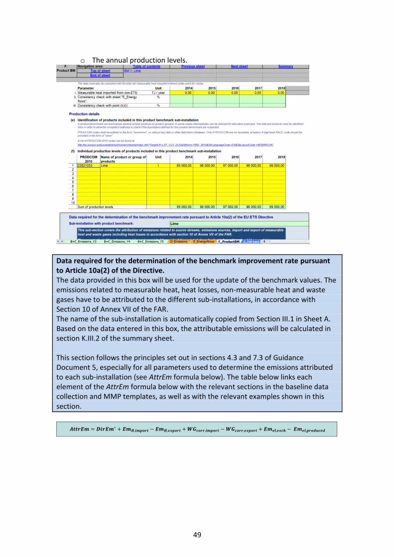
49
o The annual production levels.
Data required for the determination of the benchmark improvement rate pursuant to Article 10a(2) of the Directive. The data provided in this box will be used for the update of the benchmark values. The emissions related to measurable heat, heat losses, non-measurable heat and waste gases have to be attributed to the different sub-installations, in accordance with Section 10 of Annex VII of the FAR. The name of the sub-installation is automatically copied from Section III.1 in Sheet A. Based on the data entered in this box, the attributable emissions will be calculated in section K.III.2 of the summary sheet. This section follows the principles set out in sections 4.3 and 7.3 of Guidance Document 5, especially for all parameters used to determine the emissions attributed to each sub-installation (see AttrEm formula below). The table below links each element of the AttrEm formula below with the relevant sections in the baseline data collection and MMP templates, as well as with the relevant examples shown in this section.
𝑨𝒕𝒕𝒓𝑬𝒎 = 𝑫𝒊𝒓𝑬𝒎∗ + 𝑬𝒎𝑯,𝒊𝒎𝒑𝒐𝒓𝒕 − 𝑬𝒎𝑯,𝒆𝒙𝒑𝒐𝒓𝒕 + 𝑾𝑮𝒄𝒐𝒓𝒓,𝒊𝒎𝒑𝒐𝒓𝒕 −𝑾𝑮𝒄𝒐𝒓𝒓,𝒆𝒙𝒑𝒐𝒓𝒕 + 𝑬𝒎𝒆𝒍,𝒆𝒙𝒄𝒉 − 𝑬𝒎𝒆𝒍,𝒑𝒓𝒐𝒅𝒖𝒄𝒆𝒅
1
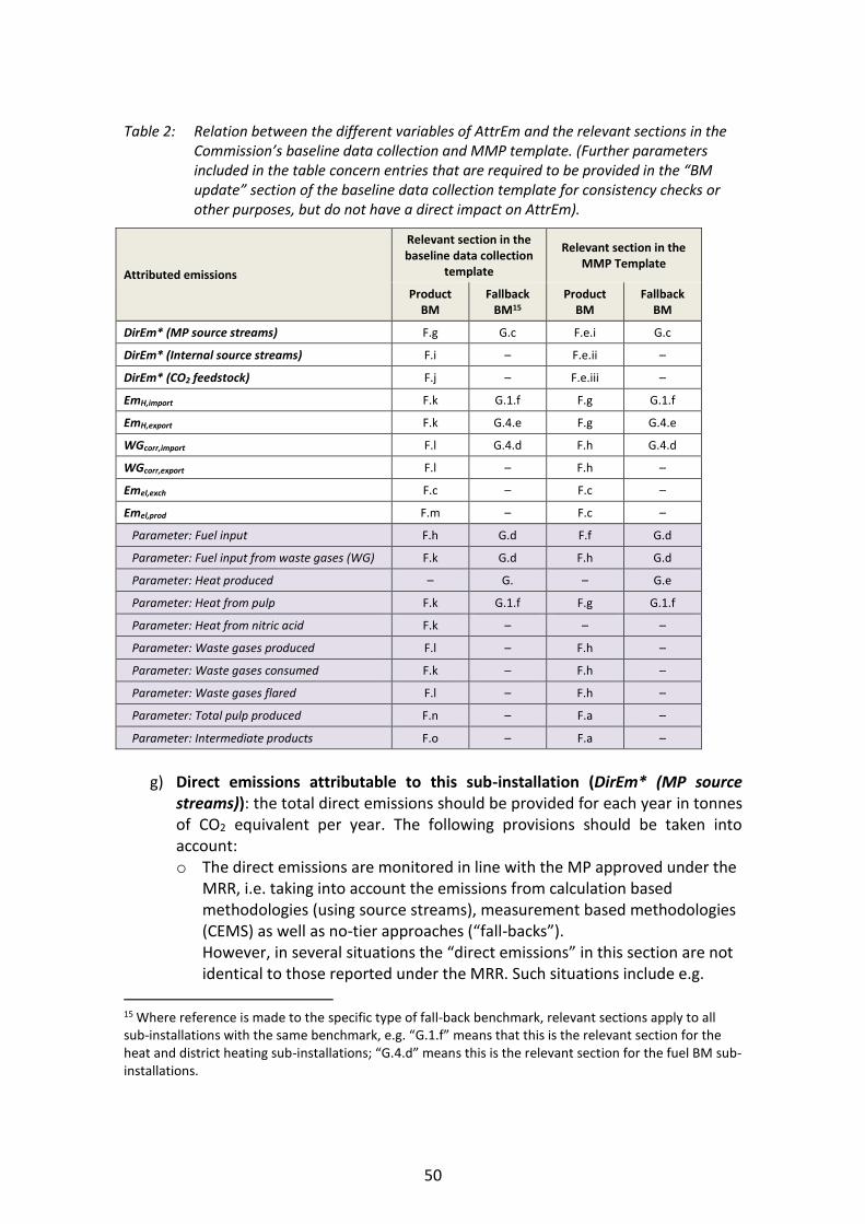
50
Table 2: Relation between the different variables of AttrEm and the relevant sections in the Commission’s baseline data collection and MMP template. (Further parameters included in the table concern entries that are required to be provided in the “BM update” section of the baseline data collection template for consistency checks or other purposes, but do not have a direct impact on AttrEm).
Attributed emissions
Relevant section in the baseline data collection
template
Relevant section in the MMP Template
Product BM
Fallback BM15
Product BM
Fallback BM
DirEm* (MP source streams) F.g G.c F.e.i G.c
DirEm* (Internal source streams) F.i – F.e.ii –
DirEm* (CO2 feedstock) F.j – F.e.iii –
EmH,import F.k G.1.f F.g G.1.f
EmH,export F.k G.4.e F.g G.4.e
WGcorr,import F.l G.4.d F.h G.4.d
WGcorr,export F.l – F.h –
Emel,exch F.c – F.c –
Emel,prod F.m – F.c –
Parameter: Fuel input F.h G.d F.f G.d
Parameter: Fuel input from waste gases (WG) F.k G.d F.h G.d
Parameter: Heat produced – G. – G.e
Parameter: Heat from pulp F.k G.1.f F.g G.1.f
Parameter: Heat from nitric acid F.k – – –
Parameter: Waste gases produced F.l – F.h –
Parameter: Waste gases consumed F.k – F.h –
Parameter: Waste gases flared F.l – F.h –
Parameter: Total pulp produced F.n – F.a –
Parameter: Intermediate products F.o – F.a –
g) Direct emissions attributable to this sub-installation (DirEm* (MP source
streams)): the total direct emissions should be provided for each year in tonnes of CO2 equivalent per year. The following provisions should be taken into account: o The direct emissions are monitored in line with the MP approved under the
MRR, i.e. taking into account the emissions from calculation based methodologies (using source streams), measurement based methodologies (CEMS) as well as no-tier approaches (“fall-backs”). However, in several situations the “direct emissions” in this section are not identical to those reported under the MRR. Such situations include e.g.
15 Where reference is made to the specific type of fall-back benchmark, relevant sections apply to all sub-installations with the same benchmark, e.g. “G.1.f” means that this is the relevant section for the heat and district heating sub-installations; “G.4.d” means this is the relevant section for the fuel BM sub-installations.

51
source streams used for the production of measurable heat, waste gases etc. In other words, care must be taken when filling the sections below to follow strictly the instructions in order to avoid double counting or omissions.
o Measurable heat: where the heat is exclusively produced for one sub-installation, the emissions may be directly attributed here via the fuel’s emissions. Wherever fuels are used to produce measurable heat which is consumed in more than one sub-installation (which includes situations with imports from and exports to other installations), the fuels should not be included in the direct emissions of the sub-installation but under point (k) below. "Imports" include measurable heat from a unit (e.g. a central power house at the installation, or a more complex steam network with several heat producing units) that supplies heat to more than one sub-installation. In such case, emissions should also not attributed here but under point (k).i. below.
o Measurable heat exported: where such heat is recovered from the process and exported, no corrections should be made here. The deduction for the associated emissions will be done based on entries under point (k).v. below.
o Waste gases: emissions from waste gases which are IMPORTED from other installations and consumed in this sub-installation, should not be included here but under point (l) below.
The specific emission factors (EF) should take into account the provisions in chapters 8 and 10, in particular Sections 10.1.2 and 10.1.3.
h) Fuel input to this sub-installation and relevant emission factor (Parameter: fuel input): in line with Annex IV, section 2.4(a) of the FAR, the following should be provided: the total fuel input in TJ per year, and the corresponding weighted emission factor in tonnes of CO2 per TJ, taking into account related energy content of each fuel which is included in the figure given under point (g), including fuels used to produce measurable heat, applying the same system boundaries as for point (g). The term "fuel" should be understood as any source stream in accordance with the M&R Regulation that is combustible and for which a net calorific value can be determined. The weighted emission factor corresponds to the accumulated emissions from the fuels divided by the total energy content. The weighted emission factor should furthermore include emissions from corresponding flue gas cleaning, if applicable. Data provided here is only used for consistency checking and have no direct impact on either the attributable emissions or the allocation.
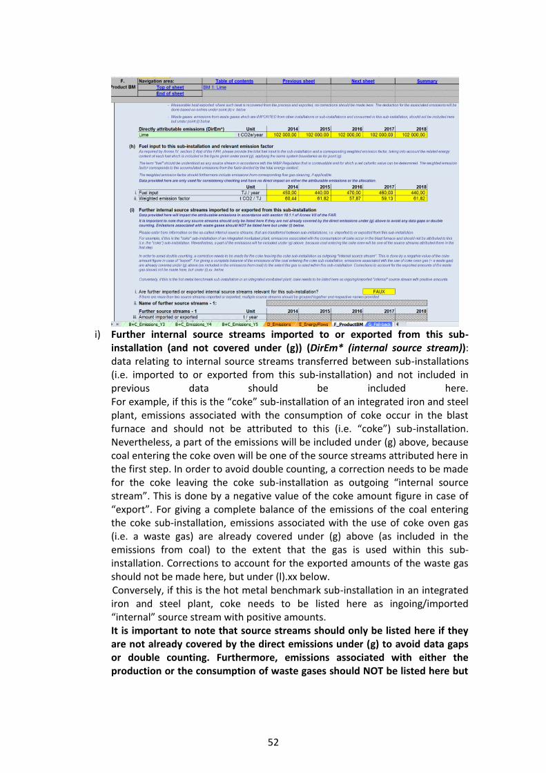
52
i) Further internal source streams imported to or exported from this sub-
installation (and not covered under (g)) (DirEm* (internal source stream)): data relating to internal source streams transferred between sub-installations (i.e. imported to or exported from this sub-installation) and not included in previous data should be included here. For example, if this is the “coke” sub-installation of an integrated iron and steel plant, emissions associated with the consumption of coke occur in the blast furnace and should not be attributed to this (i.e. “coke”) sub-installation. Nevertheless, a part of the emissions will be included under (g) above, because coal entering the coke oven will be one of the source streams attributed here in the first step. In order to avoid double counting, a correction needs to be made for the coke leaving the coke sub-installation as outgoing “internal source stream”. This is done by a negative value of the coke amount figure in case of “export”. For giving a complete balance of the emissions of the coal entering the coke sub-installation, emissions associated with the use of coke oven gas (i.e. a waste gas) are already covered under (g) above (as included in the emissions from coal) to the extent that the gas is used within this sub-installation. Corrections to account for the exported amounts of the waste gas should not be made here, but under (l).xx below. Conversely, if this is the hot metal benchmark sub-installation in an integrated iron and steel plant, coke needs to be listed here as ingoing/imported “internal” source stream with positive amounts. It is important to note that source streams should only be listed here if they are not already covered by the direct emissions under (g) to avoid data gaps or double counting. Furthermore, emissions associated with either the production or the consumption of waste gases should NOT be listed here but

53
under (l).xx. below. The operator should indicate:
i. Whether or not such source streams are relevant for this sub-installation. The template allows for two types of source streams; if there are more than two source streams imported or exported, multiple source streams should be grouped together and respective names provided.
ii. A name representing the source stream should be given. iii. The following annual data should be provided: iii. Amount imported or exported in tonnes per year iv. Net calorific value if applicable, in GJ per tonne v. Carbon content in mass percentages
vi. Biomass content, as fraction of carbon, in percentages vii. Fossil emissions, in tonnes of CO2 per year – these are automatically
calculated by the tool viii. Biomass emissions, in tonnes of CO2 per year – these are automatically
calculated by the tool ix. Energy content in TJ per year – this is automatically calculated by the
tool x. In the last line of the table, an error message is provided if data is
incomplete or inconsistent. j) Amount of GHG imported or exported as feedstock (DirEm* (CO2 feedstock)):
the amount of greenhouse gas imported or exported should be provided in tonnes of CO2 equivalent per year, in line with Annex IV, section 3.1(k) of the FAR, and with the rules set out in the M&R Regulation. Exported amounts should be entered as negative values and correspond to CO2 that is exported and not released to the atmosphere by this sub-installation.
k) Measurable heat import to and export from this sub-installation. The following data should be provided:
i. Total net heat imported, in TJ per year ii. Specific emission factor for the imported heat in tonnes of CO2 per TJ (i.
and ii. combine for EmH,import) iii. Amount of net heat imported from pulp sub-installation in TJ per year
(Parameter: Heat from pulp). See Guidance Document 6 on cross-boundary heat flows, and Guidance Document 9 on sector specific guidance for more information on this topic.
iv. Amount of heat imported from nitric acid sub-installation in TJ per year (Parameter: Heat from nitric acid). See Guidance Document 6 on cross-boundary heat flows, and Guidance Document 9 on sector specific guidance for more information on this topic.
v. Total net heat exported, in TJ per year vi. Specific emission factor for the exported heat in tonnes of CO2 per TJ.
(v. and vi. combine for EmH,export) The specific emission factors (EF) associated with the heat should take into account the provisions in FAR Annex VII sections 8 and 10, in particular sections 10.1.2 and 10.1.3.

54
For attributing emissions from cogeneration to production of heat and electricity, the “CHP tool” in section III of Sheet D should be used.
l) Waste gas balance for this sub-installation. The following data should be provided:
i. Whether or not waste gases are relevant for this sub-installation. If this is not the case, no data needs to be filled in relating to waste gases in this section.
Types of waste gases produced (Parameter: Waste gases produced) ii. Types of waste gases produced. Here a name or description of the
waste gas should be provided. The following data relate to the waste gases produced. Data provided here is only used for consistency checking and have no direct impact on either the attributable emissions or the allocation.
iii. Amounts produced: the data may be reported either in tonnes or in 1000 Nm3 (the unit can be changed via a drop-down menu). The units must be consistent with those for the net calorific value and emission factor here-after.
iv. Net calorific value: the unit in which the data are reported (GJ per 1000Nm3, or GJ per tonnes) should be consistent with the unit chosen in (iii); this is ensured automatically by the template.
v. Waste gas produced: the amount of waste gas produced in TJ per year is automatically calculated by the template.
vi. Specific emission factor of the produced waste gas in tonnes of CO2 per TJ.
Types of waste gases consumed (Parameter: Waste gases consumed) vii. Types of waste gases consumed. Here a name or description of the
waste gas should be provided. The following data relate to the waste gases consumed. This includes all types of waste gases that are consumed by this sub-installation for the purpose of the production of measurable heat, non-measurable heat (including safety flaring) or mechanical energy (other than for electricity). Amounts that are flared for reasons other than for safety flaring should be reported under the next point. Data provided here is only used for consistency checking and have no direct impact on either the attributable emissions or the allocation. viii. Amounts consumed: the data may be reported either in tonnes or in
1000 Nm3 (the unit can be changed via a drop-down menu). The units must be consistent with those for the net calorific value and emission factor here-after.
ix. Net calorific value: the unit in which the data are reported (GJ per 1000Nm3, or GJ per tonnes) should be consistent with the unit chosen in (viii); this is ensured automatically by the template.
x. Waste gas consumed: the amount of waste gas consumed in TJ per year is automatically calculated by the template.
xi. Specific emission factor of the consumed waste gas in tonnes of CO2 per TJ.

55
Types of waste gases flared (Parameter: Waste gases flared) xii. Types of waste gases flared. Here a name or description of the waste
gas should be provided. The following data relate to the waste gases flared. This includes all types of waste gases that are ultimately flared for reasons other than for safety flaring, either within or outside this sub-installation. Data provided here is used for consistency checking and have no direct impact on the attributable emissions. However, as of 2026, allocation will be reduced with respect to flaring of waste gases other than safety flaring. See Guidance Document 8 on waste gases and process emission sub-installations for more information on this topic. xiii. Amounts flared: the data may be reported either in tonnes or in 1000
Nm3 (the unit can be changed via a drop-down menu). The units must be consistent with those for the net calorific value and emission factor here-after.
xiv. Net calorific value: the unit in which the data are reported (GJ per 1000Nm3, or GJ per tonnes) should be consistent with the unit chosen in (xiii); this is ensured automatically by the template.
xv. Waste gas flared: the amount of waste gas flared in TJ per year is automatically calculated by the template.
xvi. Specific emission factor of the flared waste gas in tonnes of CO2 per TJ. Types of waste gases imported (data entered here is used for WGcorr,import) xvii. Types of waste gases imported. Here a name or description of the waste
gas should be provided. The following data relate to the waste gases imported. This includes all types of waste gases that are produced outside the system boundaries of this sub-installation, but imported to this sub-installation and used for the production of measurable heat, non-measurable heat (including safety flaring) or mechanical energy (other than for electricity).
xviii. Amounts imported: the data may be reported either in tonnes or in 1000 Nm3 (the unit can be changed via a drop-down menu). The units must be consistent with those for the net calorific value and emission factor here-after.
xix. Net calorific value: the unit in which the data are reported (GJ per 1000Nm3, or GJ per tonnes) should be consistent with the unit chosen in (xviii); this is ensured automatically by the template.
xx. Waste gas imported: the amount of waste gas imported in TJ per year is automatically calculated by the template.
xxi. Specific emission factor of the imported waste gas in tonnes of CO2 per TJ.
Types of waste gases exported (data entered here is used for WGcorr,export) xxii. Types of waste gases exported. Here a name or description of the waste
gas should be provided. The following data relate to the waste gases exported. This includes all types of waste gases that are produced within the system boundaries of this sub-

56
installation and exported from this sub-installation to any other sub-installation, or to any other installations or entities.
xxiii. Amounts exported: the data may be reported either in tonnes or in 1000 Nm3 (the unit can be changed via a drop-down menu). The units must be consistent with those for the net calorific value and emission factor here-after.
xxiv. Net calorific value: the unit in which the data are reported (GJ per 1000Nm3, or GJ per tonnes) should be consistent with the unit chosen in (xxiii); this is ensured automatically by the template.
xxv. Waste gas exported: the amount of waste gas exported in TJ per year is automatically calculated by the template.
xxvi. Specific emission factor of the exported waste gas in tonnes of CO2 per TJ.
m) Electricity production (Emel,prod): the amount of electricity produced directly from this sub-installation should be indicated in MWh per year. This includes electricity that is produced directly from this sub-installation, in line with Annex IV, section 3.1(i) of the FAR. Any electricity that is produced via intermediate measurable heat should not be listed here but under export of measurable heat under (k).v.
n) Total amount of pulp produced (Parameter: Total pulp produced): in line with section 2.4(k) of Annex IV of the FAR, the total amount of pulp produced for the short fibre kraft pulp, long fibre kraft pulp, sulphite pulp, thermo-mechanical pulp and mechanical pulp product benchmark sub-installations should be reported. If this product benchmark sub-installation is included in this list, the number of tonnes per year should be indicated. If this is not one of these product benchmarks, this table will be automatically greyed out by the template.
o) Import or export of intermediate products covered by product benchmarks (Parameter: Intermediate products). In order to avoid any double counting or gaps in attributed emissions when determining the updated benchmarks, the following information should be provided, in line with Annex IV, section 2.7(d) of the FAR:
i. Whether any import or export of intermediate products is covered by the product benchmark. If this is the case, then the following data should be provided, where relevant:
ii. Imported amounts in tonnes. iii. Exported amounts in tonnes. iv. A description of the intermediate products which are imported or
exported.
57
G “Fall-back” – Sub-installation data relating to fall-back sub-installations
G.I Historic Activity Levels and disaggregated production details
This section describes how to report on disaggregated production details for fall-back approaches. There can only be a total of 7 sub-installations: two heat benchmark sub-installations, two fuel benchmark sub-installations, and two process emissions sub-installations – with one of each deemed to be exposed to a significant risk of carbon leakage, and one not – and one district heat sub-installation. These data will serve two purposes: the determination of the amount of free allocation based on fall-back benchmark sub-installations, and the determination of the improvement rates of fall-back benchmark values. See Guidance Document 1 on general guidance for a discussion on the maximum number of sub-installations with fall-back approaches. For more information on how to define sub-installations please refer to Guidance Document 2 on allocation approaches. The operators should only report data on sub-installations that are present in the installation. In most cases, the data requested are annual values. Data can be derived from a range of data sources. See Guidance Document 5 on Monitoring & Reporting for the FAR for more guidance on this topic. In the NIMs baseline data template, each section in this chapter starts with an overview of historical activity levels taken from the Sheet ‘EnergyFlows’.
G.I.1 Fall-Back Sub-installation 1, heat benchmark carbon leakage
This section covers sub-installations covered by a heat benchmark and deemed to be exposed to a significant risk of carbon leakage. The tool provides automatically the name of the sub-installation if it is relevant for this installation, based on information provided in section A.III.2 (“Sub-installations with fall-back approaches”).
a) Historical activity levels are copied automatically from Sheet E_EnergyFlows, in section E.II.r. The tool will automatically determine, based on the start of normal operation indicated in section A.III, whether the sub-installation has been operating less than one year during the baseline period. If this is the case, the historic activity level will be determined based on the first calendar year after the start of normal operation, in line with the third sub-paragraph of Article 15(7). The corresponding entries (i.e. historic activity level for either year 2019 or year 2020) are to be entered in the last column of the table. This can however only be done at a later stage, once these values are known.
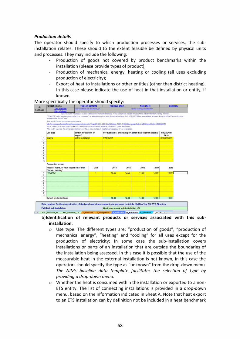
58
Production details The operator should specify to which production processes or services, the sub-installation relates. These should to the extent feasible be defined by physical units and processes. They may include the following:
- Production of goods not covered by product benchmarks within the installation (please provide types of product);
- Production of mechanical energy, heating or cooling (all uses excluding production of electricity);
- Export of heat to installations or other entities (other than district heating). In this case please indicate the use of heat in that installation or entity, if known.
More specifically the operator should specify:
b) Identification of relevant products or services associated with this sub-
installation: o Use type: The different types are: “production of goods”, “production of
mechanical energy”, “heating” and “cooling” for all uses except for the production of electricity; In some case the sub-installation covers installations or parts of an installation that are outside the boundaries of the installation being assessed. In this case it is possible that the use of the measurable heat in the external installation is not known, in this case the operators should specify the type as “unknown” from the drop-down menu. The NIMs baseline data template facilitates the selection of type by providing a drop-down menu.
o Whether the heat is consumed within the installation or exported to a non-ETS entity. The list of connecting installations is provided in a drop-down menu, based on the information indicated in Sheet A. Note that heat export to an ETS installation can by definition not be included in a heat benchmark

59
sub-installation. See Guidance Document 6 on Cross-boundary heat flows for more guidance on this topic.
o The name of the product for which the heat is consumed, or heat export for uses other than “district heating”.
o The relevant PRODCOM 2010 code for the activity related to the heat consumption or heat export to non-ETS entities. A list of PRODCOM 2010 codes can be found at: http://ec.europa.eu/eurostat/ramon/nomenclatures/index.cfm?TargetUrl=LST_CLS
_DLD&StrNom=PRD_2010&StrLanguageCode=EN&StrLayoutCode=HIERARCHIC. The PRODCOM codes should be entered in the format “nnnnnnnn”, i.e. without any dots or other delimiters between the numbers. If PRODCOM codes are not available for the specific product, 4-digit level NACE codes should be provided, in the format “nnnn”. NACE codes can also be used instead of PRODCOM codes if several similar products within the same NACE sector are covered. The PRODCOM/NACE codes should be used to verify the carbon leakage status of activities within the sub-installation. Note that in case of heat export to non-ETS entities, the carbon leakage exposure factor for carbon leakage exposed sectors can only be used if the heat exporter provides satisfactory evidence that it exports heat to a non-ETS entity that is exposed to a significant risk of carbon leakage: the operator will for example provide a list of his customers consuming the heat, along with the NACE codes of these customers and the amounts of heat delivered to them.
Production levels: unit and production levels of each of the products or the amount of heat exported. This second table automatically copies the product name or heat export listed in (b).
Data required for the determination of the benchmark improvement rate pursuant to Article 10a(2) of the Directive. The data provided in this box will be used for the update of the benchmark values. The emissions related to measurable heat, heat losses, non-measurable heat and waste gases have to be attributed to the different sub-installations, in accordance with section 10 of Annex VII of the FAR. This section follows the principles set out in sections 4.3 and 7.3 of Guidance Document 5, especially for all parameters used to determine the emissions attributed to each sub-installation (see AttrEm formula below). Table 2 on page 50 links each element of the AttrEm formula below with the relevant sections in the baseline data collection and MMP templates, as well as with the relevant examples shown in this section.
𝑨𝒕𝒕𝒓𝑬𝒎 = 𝑫𝒊𝒓𝑬𝒎∗ + 𝑬𝒎𝑯,𝒊𝒎𝒑𝒐𝒓𝒕 − 𝑬𝒎𝑯,𝒆𝒙𝒑𝒐𝒓𝒕 + 𝑾𝑮𝒄𝒐𝒓𝒓,𝒊𝒎𝒑𝒐𝒓𝒕 −𝑾𝑮𝒄𝒐𝒓𝒓,𝒆𝒙𝒑𝒐𝒓𝒕 + 𝑬𝒎𝒆𝒍,𝒆𝒙𝒄𝒉 − 𝑬𝒎𝒆𝒍,𝒑𝒓𝒐𝒅𝒖𝒄𝒆𝒅
1
Based on the data entered in this box, the attributable emissions will be calculated in section K.III.2 of the summary sheet.

60
The operator should ensure that the following elements are provided:
c) Direct emissions attributable to this sub-installation (DirEm* (MP source streams)): the total direct emissions should be provided for each year in tonnes of CO2 equivalent per year. The following provisions should be taken into account: o The direct emissions are monitored in line with the MP approved under the
MRR, i.e. taking into account the emissions from calculation based methodologies (using source streams), measurement based methodologies (CEMS) as well as no-tier approaches (“fall-backs”). However, in several situations the “direct emissions” in this section are not identical to those reported under the MRR. Such situations include e.g. source streams used for the production of measurable heat, waste gases etc. In other words, care must be taken to fill the sections here-after following strictly the instructions provided in order to avoid double counting or omissions.
o Measurable heat: where the heat is exclusively produced for one sub-installation, the emissions may be directly attributed here via the fuel’s emissions. Wherever fuels are used to produce measurable heat which is consumed in more than one sub-installation (e.g. a central power house at the installation, or a more complex steam network with several heat producing units), the fuels should not be included in the direct emissions of the sub-installation but under point (f).i. below.
o Waste gases: emissions associated with measurable heat produced from waste gases imported from other installations or sub-installations and used in this sub-installation should not be included here, but under point (f).xiii. here-after.
d) Fuel input to this sub-installation and relevant emission factor: the total fuel input in TJ per year, and the corresponding weighted emission factor in tonnes of CO2 per TJ, taking into account related energy content of each fuel, should be provided, in line with section 2.4(a) of FAR Annex IV. The term "fuel" should be understood as any source stream in accordance with the M&R Regulation that is combustible and for which a net calorific value can be determined. The weighted emission factor corresponds to the accumulated emissions from the fuels divided by the total energy content. The weighted emission factor should furthermore include emissions from corresponding flue gas cleaning, if applicable. The fuel input from waste gases includes the corresponding energy input to produce the measurable heat included in this sub-installation. The values entered here are used for the waste gas balance in section E.III.h. Data provided here is only used for consistency checking and have no direct impact on either the attributable emissions or the allocation.

61
e) Measurable heat produced (Parameter: Heat produced):: the measurable heat
produced should be entered here, in line with section 3.2(a) of Annex IV of the FAR. This value is usually different from the sub-installation’s activity level listed under point (a) above, as it takes into account the heat losses in addition to the net amounts of measurable heat consumed or exported to non-ETS entities, and disregards heat imports, which are to be entered under (f) here-after. Further guidance is provided in example MH-5 in section 7.3 of Guidance Document 5.
f) Measurable heat imported (data entered here used for EmH,import). Here the amount of measurable heat imported from each of the following sources should be entered. Do not include here any heat imports from “non-eligible” sources, i.e. installations not covered by the EU ETS, or heat produced in nitric acid sub-installations. The specific emission factors (EF) should take into account the provisions in chapters 8 and 10, in particular sections 10.1.2 and 10.1.3 thereof.
Net heat imported (other sources): this includes heat imported from other installations, or, where measurable heat is consumed by more than one sub-installation, heat produced onsite and consumed within this sub-installation. Measurable heat imported from any product BM sub-installation, pulp production, measurable heat recovered from fuel BM sub-installations or from waste gases should not be included here, because separate entry fields are provided for these figures. i. Total net heat imported, in TJ per year.
ii. Specific emission factor for the imported heat in tonnes of CO2 per TJ. Heat from product benchmark: this includes measurable heat imported from product benchmark sub-installations with the exception of measurable heat from sub-installations producing pulp or nitric acid.

62
iii. Amount of net heat imported from product benchmark sub-installations in TJ per year.
iv. Specific emission factor for the imported heat in tonnes of CO2 per TJ. Heat from pulp: this includes measurable heat from sub-installations producing pulp. v. Amount of net heat imported from pulp benchmark sub-installations in TJ
per year. vi. Specific emission factor for the imported heat in tonnes of CO2 per TJ. Heat from fuel benchmark: this includes measurable heat recovered from waste heat from fuel BM sub-installations.
vii. Amount of net heat imported from fuel benchmark sub-installations in TJ per year.
viii. Specific emission factor for the imported heat in tonnes of CO2 per TJ. Heat from waste gases: this includes measurable heat which is produced from waste gases.
ix. Amount of net heat imported from waste gases in TJ per year. x. Specific emission factor for the imported heat in tonnes of CO2 per TJ.
G.I.2 Fall-Back Sub-installation 2, heat benchmark non-carbon leakage
This section covers sub-installations covered by a heat benchmark but not deemed to be exposed to a significant risk of carbon leakage. The tool provides automatically the name of the sub-installation if it is relevant for this installation, based on information provided in section A.III.2 (“Sub-installations with fall-back approaches”). For this sub-installation, operators need to provide the same data as for the sub-installation discussed in section G.I.1. Operators should be careful and ensure that only activities not deemed to be exposed to a significant risk of carbon leakage are included in this sub-installation.
G.I.3 Fall-Back Sub-installation 3, district heating
This section covers district heating sub-installations. The tool provides automatically the name of the sub-installation if it is relevant for this installation, based on information provided in section A.III.2 (“Sub-installations with fall-back approaches”). For this sub-installation, operators need to provide the same data as for the sub-installation discussed in section G.I.1, with the exception of section (b), in which the use type is already indicated as District heating, there is no need to specify whether the heat is exported or not (it will always be exported to a district heating network), and the name of the district heating network should be provided (instead of the name of the product for which the heat is consumed in section G.I.1). For more guidance on the definition of a district heating sub-installation see Guidance Document 2 on allocation approaches
63
G.I.4 Fall-Back Sub-installation 4, fuel benchmark carbon leakage
This section covers sub-installations covered by a fuel benchmark and deemed to be exposed to a significant risk of carbon leakage. The tool provides automatically the name of the sub-installation if it is relevant for this installation, based on information provided in section A.III.2 (“Sub-installations with fall-back approaches”). The following guidance is specific for this sub-installation; for the remaining sections, the same data as for the sub-installation discussed in section G.I.1 is to be provided:
- In section (b), there is no need to specify whether the fuel is consumed on-site or not (it will always be consumed on site), and the name of the product or heat export is replaced by the name of the product or service type: the operator should list here to which product processes or services this sub-installation relates, which may include the production of goods not covered by product benchmarks within the installation (in this case the types of products should be indicated), or the production of mechanical energy, heating or cooling (all uses excluding production of electricity).
- In section (c), direct emissions monitored in line with the MP approved under the MRR, i.e. taking into account the emissions from calculation based methodologies (using source streams), measurement based methodologies (CEMS) as well as no-tier approaches (“fall-backs”) should be entered. Emissions from the combustion of waste gases should however not be included here but under point (d).iii. here-after.
- In section (d), values for i. and ii. are automatically calculated based on data entered in (a) and (c). Under iii. and iv. the fuel input from waste gases and the corresponding emission factor has to be entered, respectively.
- In section (e), only the amount of net heat exported in TJ per year needs to be provided along with its specific emission factor. This concerns any waste heat recovered and eligible for a heat benchmark or district heating sub-installation.
G.I.5 Fall-Back Sub-installation 5, fuel benchmark non-carbon leakage
This section covers sub-installations covered by a fuel benchmark and not deemed to be exposed to a significant risk of carbon leakage. The tool provides automatically the name of the sub-installation if it is relevant for this installation, based on information provided in section A.III.2 (“Sub-installations with fall-back approaches”). For this sub-installation, operators need to provide the same data as for the sub-installation discussed in section G.I.4. Operators should be careful and ensure that only activities deemed not to be exposed to a significant risk of carbon leakage are included in this sub-installation.
64
G.I.6 Fall-Back Sub-installation 6, process emissions carbon leakage
This section covers process emissions sub-installations16 deemed to be exposed to a significant risk of carbon leakage. The tool provides automatically the name of the sub-installation if it is relevant for this installation, based on information provided in section A.III.2 (“Sub-installations with fall-back approaches”).
a) Historic activity levels should be provided in tonnes of CO2 equivalent for each year. The values entered should include eligible emissions from any waste gases as determined in section D.IV. The tool will automatically determine, based on the start of normal operation indicated in section A.III, whether the sub-installation has been operating less than one year during the baseline period. If this is the case, the historic activity level will be determined based on the first calendar year after the start of normal operation, in line with the third sub-paragraph of Article 15(7). The corresponding entries (i.e. historic activity level for either year 2019 or year 2020) are to be entered in the last column of the table. This can however only be done at a later stage, once these values are known.
Production details The operator should specify to which products or services the sub-installation relates. These should to the extent feasible be defined by physical units and processes. This type of sub-installation always relates to production of goods not covered by product benchmarks within the installation. More specifically the operator should specify:
b) Identification of relevant products or services associated with this sub-installation:
o Process emission type: The different types are: “N2O”, “PFCs”, “CO2 (waste gas corrected)”, “reduction of metals compounds”, ”removal of impurities”, ”decomposition of carbonates”, “chemical synthesis”, “carbon containing materials”, “reduction of metalloid oxides and non-metal oxides”. The different types of process emissions are defined in Article 2(10) of the FAR. The NIMs baseline data template facilitates the selection of type by providing a drop-down menu.
o The name of the product or service type to which the process emissions relate
o The relevant PRODCOM 2010 code for the activity related to the process emissions. A list of PRODCOM 2010 codes can be found at http://ec.europa.eu/eurostat/ramon/nomenclatures/index.cfm?TargetUrl=LST_CLS_DLD&StrNom=PRD_2010&StrLanguageCode=EN&StrLayoutCode=HIERAR
CHIC. The PRODCOM codes should be entered in the format “nnnnnnnn”, i.e. without any dots or other delimiters between the
16 It is of utmost importance of not confusing the process emissions as referred to in the MRGs and the process emission sub-installation that is relevant for allocation purposes. E.g. emissions form flue gas cleaning are “process emissions” according to Annex II MRR, but not eligible for free allocation according to Article 2(1) of the FAR. Therefore emissions from flue gas cleaning are reported in the Sheets B+C “, but they shouldn’t be related to a process emissions sub-installation See Guidance Document 2 on allocation approaches for further clarifications.

65
numbers. If PRODCOM codes are not available for the specific product, 4-digit level NACE codes should be provided, in the format “nnnn”. NACE codes can also be used instead of PRODCOM codes if several similar products within the same NACE sector are covered. The PRODCOM/NACE codes should be used to verify the carbon leakage status of activities within the sub-installation.
c) Disaggregation of production levels: unit and production levels of each of the
products or service. This second table automatically copies the product name or service type listed in (e)..
G.I.7 Fall-Back Sub-installation 7, process emissions non carbon leakage
This section covers process emissions sub-installations17 not deemed to be exposed to a significant risk of carbon leakage. For this sub-installation, operators need to provide the same data as for the sub-installation discussed in section G.I.6. Operators should be careful and ensure that only activities deemed not to be exposed to a significant risk of carbon leakage are included in this sub-installation.
17 It is of utmost importance of not confusing the process emissions as referred to in the MRGs and the process emission sub-installation that is relevant for allocation purposes. E.g. emissions form flue gas cleaning are “process emissions” according to Annex II MRR, but not eligible for free allocation according to Article 2(1) of the FAR. Therefore emissions from flue gas cleaning are reported in the Sheets B+C, but they shouldn’t be related to a process emissions sub-installation. See Guidance Document 2 on allocation approaches for further clarifications.

66
H “Special BM” – Special data for some product benchmarks
For some product benchmark sub-installations the historical activity level or allocation needs to be calculated according to a special methodology. This section gives guidance on the data collection required to apply these special methodologies. The methodologies are specified in Annex III of the FAR. For more guidance on special methodologies, see Guidance Document 9 on sector specific guidance. In the NIMs baseline data template, the historical activity levels determined in this section are automatically copied to Sheet F.
H.I CWT (Refinery products)
This section gives guidance to data collection for refinery sub-installations. This section is only relevant for installations that contain a refinery sub-installation. The NIMs baseline data template automatically shows in a) whether this section is relevant based on the data collected according to section A.III.1 (“Product benchmark sub-installations”) . See Chapter 1 of Guidance Document 9 on sector specific guidance for more information about refinery sub-installations).
b) The operator should specify the relevant throughput in kilotonnes throughput for each CWT function. The following abbreviations are used in the table: F for net fresh feed, R for reactor feed including recycle, P for product feed, and SG for synthesis gas production for POX units. See Annex II.1 of the FAR for definitions of CWT functions and definitions of throughput for each function. The tool will automatically determine, based on the start of normal operation indicated in section A.III, whether the sub-installation has been operating less than one year during the baseline period. If this is the case, the historic activity level will be determined based on the first calendar year after the start of normal operation, in line with the third sub-paragraph of Article 15(7). The corresponding entries for either year 2019 or year 2020 are to be entered in the last column of the table. This can however only be done at a later stage, once these values are known. See Chapter 1 of Guidance Document 9 on sector specific guidance for additional guidance to these definitions and to data quality.
c) The annual Historic Activity Level in CWT (in tonne) per year should then be calculated from the specified throughputs of the different functions. This should be done according to the part of the formula in Annex III to the FAR point 1 before determining the arithmetic mean. See Annex II.1 to the FAR for values of CWT factors. The NIMs baseline data template automatically performs the required calculation. See Chapter 1 of Guidance Document 9 on sector specific guidance for guidance on the calculation of the annual historical activity levels of a refinery sub-installation.
FAR
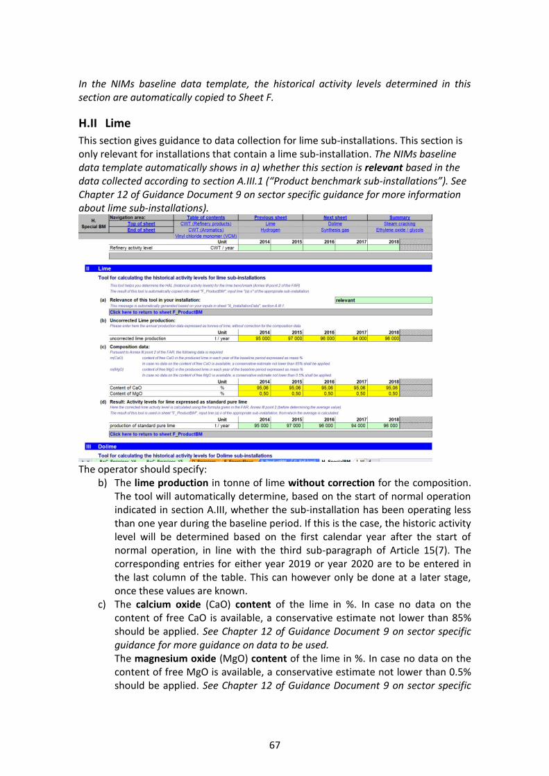
67
In the NIMs baseline data template, the historical activity levels determined in this section are automatically copied to Sheet F.
H.II Lime
This section gives guidance to data collection for lime sub-installations. This section is only relevant for installations that contain a lime sub-installation. The NIMs baseline data template automatically shows in a) whether this section is relevant based in the data collected according to section A.III.1 (“Product benchmark sub-installations”). See Chapter 12 of Guidance Document 9 on sector specific guidance for more information about lime sub-installations).
The operator should specify:
b) The lime production in tonne of lime without correction for the composition. The tool will automatically determine, based on the start of normal operation indicated in section A.III, whether the sub-installation has been operating less than one year during the baseline period. If this is the case, the historic activity level will be determined based on the first calendar year after the start of normal operation, in line with the third sub-paragraph of Article 15(7). The corresponding entries for either year 2019 or year 2020 are to be entered in the last column of the table. This can however only be done at a later stage, once these values are known.
c) The calcium oxide (CaO) content of the lime in %. In case no data on the content of free CaO is available, a conservative estimate not lower than 85% should be applied. See Chapter 12 of Guidance Document 9 on sector specific guidance for more guidance on data to be used. The magnesium oxide (MgO) content of the lime in %. In case no data on the content of free MgO is available, a conservative estimate not lower than 0.5% should be applied. See Chapter 12 of Guidance Document 9 on sector specific
68
guidance for more guidance on data to be used. The tool will automatically determine, based on the start of normal operation indicated in section A.III, whether the sub-installation has been operating less than one year during the baseline period. If this is the case, the historic activity level will be determined based on the first calendar year after the start of normal operation, in line with the third sub-paragraph of Article 15(7). The corresponding entries for either year 2019 or year 2020 are to be entered in the last column of the table. This can however only be done at a later stage, once these values are known.
d) The annual historical activity levels for lime, in tonnes of standard pure lime per year should then be calculated. This should be done according to the part of the formula in Annex III to the FAR point 2 before determining the arithmetic mean. The NIMs baseline data template automatically performs the required calculation. See also Chapter 12 of Guidance Document 9 on sector specific guidance.
In the NIMs baseline data template, the historical activity levels determined in this section are automatically copied to Sheet F.
H.III Dolime
This section gives guidance to data collection for dolime sub-installations. This section is only relevant for installations that contain a dolime sub-installation. The NIMs baseline data template automatically shows in a) whether this section is relevant based in the data collected according to section A.III.1 (“Product benchmark sub-installations”). See Chapter 13 of Guidance Document 9 on sector specific guidance for more information about dolime sub-installations). The operator should specify:
b) The dolime production in tonne of lime without correction for the composition. The tool will automatically determine, based on the start of normal operation indicated in section A.III, whether the sub-installation has been operating less than one year during the baseline period. If this is the case, the historic activity level will be determined based on the first calendar year after the start of normal operation, in line with the third sub-paragraph of Article 15(7). The corresponding entries for either year 2019 or year 2020 are to be entered in the last column of the table. This can however only be done at a later stage, once these values are known.
c) The calcium oxide (CaO) content of the dolime in %. In case no data on the content of free CaO is available, a conservative estimate not lower than 52% should be applied. See Chapter 13 of Guidance Document 9 on sector specific guidance for more guidance on data to be used. The magnesium oxide (MgO) content of the dolime in %. In case no data on the content of free MgO is available, a conservative estimate not lower than 33% shall be applied. See Chapter 13 of Guidance Document 9 on sector specific guidance for more guidance on data to be used.

69
The tool will automatically determine, based on the start of normal operation indicated in section A.III, whether the sub-installation has been operating less than one year during the baseline period. If this is the case, the historic activity level will be determined based on the first calendar year after the start of normal operation, in line with the third sub-paragraph of Article 15(7). The corresponding entries for either year 2019 or year 2020 are to be entered in the last column of the table. This can however only be done at a later stage, once these values are known.
d) The annual historical activity level in metric ton of standard pure dolime per year according to the part of the formula in Annex III to the FAR point 3 before determining the arithmetic mean, should then be calculated. The NIMs baseline data template automatically performs the required calculation. See also Chapter 13 of Guidance Document 9 on sector specific guidance.
In the NIMs baseline data template, the historical activity levels determined in this section are automatically copied to Sheet F.
H.IV Steam cracking
This section gives guidance to data collection for steam cracking sub-installations. This section is only relevant for installations that contain a steam cracking sub-installation. The NIMs baseline data template automatically shows in a) whether this section is relevant based in the data collected according to section A.III.1 (“Product benchmark sub-installations”). See Chapter 42 of Guidance Document 9 on sector specific guidance for more information about steam cracking sub-installations). The operator should specify:
b) The total production of high value chemicals in tonne per year without any corrections. The tool will automatically determine, based on the start of normal operation indicated in section A.III, whether the sub-installation has been operating less than one year during the baseline period. If this is the case, the historic activity level will be determined based on the first calendar year after the start of normal operation, in line with the third sub-paragraph of Article 15(7). The corresponding entries for either year 2019 or year 2020 are to be entered in the last column of the table. This can however only be done at a later stage, once these values are known. See Chapter 42 of Guidance Document 9 on sector specific guidance for the definition of high value chemicals.
c) Supplemental feed of hydrogen in tonne of hydrogen per year. Supplemental feed of ethylene in tonne of ethylene per year. Supplemental feed of high value chemicals other than hydrogen and ethylene in tonne of high value chemicals per year. The tool will automatically determine, based on the start of normal operation indicated in section A.III, whether the sub-installation has been operating less than one year during the baseline period. If this is the case, the historic activity level will be determined based on the first calendar year after the start of
70
normal operation, in line with the third sub-paragraph of Article 15(7). The corresponding entries for either year 2019 or year 2020 are to be entered in the last column of the table. This can however only be done at a later stage, once these values are known.
d) The annual historical activity level in metric ton of net high value chemicals per year should then be calculated. This should be done according to the part of the formula in Annex III of the FAR point 4 before determining the arithmetic mean. The NIMs baseline data template automatically performs the required calculation. See also Chapter 42 of Guidance Document 9 on sector specific guidance.
In the NIMs baseline data template, the historical activity levels determined in this section are automatically copied to Sheet F. The preliminary allocation to steam cracking sub-installations is determined according to Article 19 of the FAR. See also Chapter 42 of Guidance Document 9 on sector specific guidance. The preliminary allocation can be determined from the reported data. The NIMs baseline data template calculates allocation correction. No action is required from the operator.
H.V Aromatics
This section gives guidance to data collection for sub-installations that produce aromatics. This section is only relevant for installations that contain an aromatics sub-installation. The NIMs baseline data template automatically shows in a) whether this section is relevant based in the data collected according to section A.III.1 (“Product benchmark sub-installations”). See Chapter 43 of Guidance Document 9 on sector specific guidance for more information about sub-installations that produce aromatics)
b) The operator should specify the relevant throughput in kilotonnes throughput for each CWT function. The following abbreviations are used in the table: F for net fresh feed, and P for product feed. See Annex II.2 to the FAR for definitions of CWT functions and definitions of throughput for each function. The tool will automatically determine, based on the start of normal operation indicated in section A.III, whether the sub-installation has been operating less than one year during the baseline period. If this is the case, the historic activity level will be determined based on the first calendar year after the start of normal operation, in line with the third sub-paragraph of Article 15(7). The corresponding entries for either year 2019 or year 2020 are to be entered in the last column of the table. This can however only be done at a later stage, once these values are known. See Chapter 43 of Guidance Document 9 on sector specific guidance for additional guidance to these definitions and to data quality.
c) The annual Historic Activity Level in CWT (in tonne) per year from the specified throughputs of the different functions should then be calculated. This should be done according to the part of the formula in Annex III of the FAR point 5
71
before determining the arithmetic mean. See Annex II.2 of the FAR for values of CWT factors. The NIMs baseline data template automatically performs the required calculation. See Chapter 43 of Guidance Document 9 on sector specific guidance for guidance on the calculation of the annual historical activity levels of an aromatics sub-installation.
Important note: The reporting is done in kilotonnes, but the benchmark is expressed in t CO2/CWT, where CWT is expressed in tonnes. Therefore the results in this section are multiplied with a factor of 1000, which is not explicitly mentioned in Annex III point 5 of the FAR. In the NIMs baseline data template, the historical activity levels determined in this section are automatically copied to Sheet F.
H.VI Hydrogen
This section gives guidance to data collection for hydrogen sub-installations. This section is only relevant for installations that contain a hydrogen sub-installation. The NIMs baseline data template automatically shows in a) whether this section is relevant based in the data collected according to section A.III.1 (“Product benchmark sub-installations”). See Chapter 50 of Guidance Document 9 on sector specific guidance for more information about hydrogen sub-installations) The operator should specify:
b) The hydrogen production in 1000 Nm3 per year without any corrections for purity; norm cubic meters refer to the volume at 0°C and 101.325 kPa. The tool will automatically determine, based on the start of normal operation indicated in section A.III, whether the sub-installation has been operating less than one year during the baseline period. If this is the case, the historic activity level will be determined based on the first calendar year after the start of normal operation, in line with the third sub-paragraph of Article 15(7). The corresponding entries for either year 2019 or year 2020 are to be entered in the last column of the table. This can however only be done at a later stage, once these values are known.
c) The production volume fraction of pure hydrogen in % at 0°C and 101.325 kPa. The value can be entered either as 0.XX or XX% (e.g. 0.95 or 95%). The tool will automatically determine, based on the start of normal operation indicated in section A.III, whether the sub-installation has been operating less than one year during the baseline period. If this is the case, the historic activity level will be determined based on the first calendar year after the start of normal operation, in line with the third sub-paragraph of Article 15(7). The corresponding entries for either year 2019 or year 2020 are to be entered in the last column of the table. This can however only be done at a later stage, once these values are known.
d) The annual historical activity level in metric ton of 100% pure hydrogen per year should then be calculated. This should be done according to the part of

72
the formula in Annex III of the FAR point 6 before determining the arithmetic mean. The NIMs baseline data template automatically performs the required calculation. If the result is a negative value, it is replaced by zero. See also Chapter 50 of Guidance Document 9 on sector specific guidance.
In the NIMs baseline data template, the historical activity levels determined in this section are automatically copied to Sheet F.
H.VII Synthesis gas
This section gives guidance to data collection for synthesis gas sub-installations. This section is only relevant for installations that contain a synthesis gas sub-installation. The NIMs baseline data template automatically shows in a) whether this section is relevant based in the data collected according to section A.III.1 (“Product benchmark sub-installations”). See Chapter 51 of Guidance Document 9 on sector specific guidance for more information about synthesis gas sub-installations) The operator should specify:
b) The synthesis gas production in 1000 Nm3 per year without any corrections for hydrogen content; norm cubic meters refer to the volume at 0°C and 101.325 kPa. The tool will automatically determine, based on the start of normal operation indicated in section A.III, whether the sub-installation has been operating less than one year during the baseline period. If this is the case, the historic activity level will be determined based on the first calendar year after the start of normal operation, in line with the third sub-paragraph of Article 15(7). The corresponding entries for either year 2019 or year 2020 are to be entered in the last column of the table. This can however only be done at a later stage, once these values are known.
c) The production volume fraction of pure hydrogen in % at 0°C and 101.325 kPa. The value can be entered either as 0.XX or XX% (e.g. 0.50 or 50%). The tool will automatically determine, based on the start of normal operation indicated in section A.III, whether the sub-installation has been operating less than one year during the baseline period. If this is the case, the historic activity level will be determined based on the first calendar year after the start of normal operation, in line with the third sub-paragraph of Article 15(7). The corresponding entries for either year 2019 or year 2020 are to be entered in the last column of the table. This can however only be done at a later stage, once these values are known.
d) The annual historical activity level in metric ton per year of synthesis gas with a standardized hydrogen content of 47% should then be calculated. This should be done according to the part of the formula in Annex III of the FAR point 7 before determining the arithmetic mean. The NIMs baseline data template automatically performs the required calculation. If the result is a negative value, it is replaced by zero. See also Chapter 51 of Guidance Document 9 on sector specific guidance.

73
In the NIMs baseline data template, the historical activity levels determined in this section are automatically copied to Sheet F.
H.VIII Ethylene oxide/glycols
This section gives guidance to data collection for ethylene oxide/glycols sub-installations. This section is only relevant for installations that contain an ethylene oxide/glycols sub-installation. The NIMs baseline data template automatically shows in a) whether this section is relevant based in the data collected according to section A.III.1 (“Product benchmark sub-installations”). See Chapter 46 of Guidance Document 9 on sector specific guidance for more information about ethylene oxide/glycols sub-installations).
b) The operator should specify: o Ethylene oxide production in tonnes per year o Monoethylene glycol production in tonnes per year o Diethylene glycol production in tonnes per year o Triethylene glycol production in tonnes per year o Sum of productions specified above in tonnes per year. The NIMs baseline
data template automatically calculates this sum The table indicates the conversion factor for each substance relative to ethylene oxide, as used in the calculation (CF(EOE)). The tool will automatically determine, based on the start of normal operation indicated in section A.III, whether the sub-installation has been operating less than one year during the baseline period. If this is the case, the historic activity level will be determined based on the first calendar year after the start of normal operation, in line with the third sub-paragraph of Article 15(7). The corresponding entries for either year 2019 or year 2020 are to be entered in the last column of the table. This can however only be done at a later stage, once these values are known.
c) The annual historical activity level in metric ton per year ethylene oxide/glycols should then be calculated. This should be done according to the part of the formula in Annex III to the FAR point 8 before determining the arithmetic mean. The NIMs baseline data template automatically performs the required calculation. See also Chapter 46 of Guidance Document 9 on sector specific guidance.
In the NIMs baseline data template, the historical activity levels determined in this section are automatically copied to Sheet F.
H.IX Vinyl chloride monomer (VCM)
This section gives guidance to data collection for vinyl chloride monomer (VCM) sub-installations. This section is only relevant for installations that contain a VCM sub-installation. The NIMs baseline data template automatically shows in a) whether this section is relevant based in the data collected according to section A.III.1 (“Product

74
benchmark sub-installations”). See Chapter 47 of Guidance Document 9 on sector specific guidance for more information about VCM sub-installations) The operator should specify:
b) Emission related data, in particular: o Direct emissions attributed to this sub-installation in tCO2 per year o Net measurable heat imported in TJ per year o Measurable heat consumption from H2 combustion in TJ per year o Total direct emissions in tCO2 per year. This is equal to the direct emissions
attributed to the sub-installation (first bullet) plus the net measurable heat import (second bullet) times 62.3 tCO2/TJ. The NIMs baseline data template automatically performs this calculation
o Hydrogen related emissions in tCO2 per year. This is equal to the measurable heat consumption from H2 combustion (third bullet) times 56.1 tCO2/TJ. The NIMs baseline data template automatically performs this calculation
The tool will automatically determine, based on the start of normal operation indicated in section A.III, whether the sub-installation has been operating less than one year during the baseline period. If this is the case, the historic activity level will be determined based on the first calendar year after the start of normal operation, in line with the third sub-paragraph of Article 15(7). The corresponding entries for either year 2019 or year 2020 are to be entered in the last column of the table. This can however only be done at a later stage, once these values are known.
The factor for allocation corrected as described in Article 20 of the FAR should then be calculated. This factor is equal to the direct emissions divided by the sum of direct emissions and emissions related to hydrogen combustion. The NIMs baseline data template automatically performs the required calculation. See Chapter 47 of Guidance Document 9 on sector specific guidance for more guidance to the calculation of allocation for VCM sub-installations.

75
I “MS specific” – Additional data requirements by the Member State
I.I To be defined by the Member State
In this Sheet, the operator will find Member State specific requirements if relevant. Additional information related to these requirements should be provided by the relevant competent authority.

76
J “Comments” – Comments and further information
J.I Documents supporting this report
As indicated in section 2.1 of this Guidance Document, two documents need to be submitted together with the NIMs baseline data template. For each of these documents, the operator should provide a file name (if the document is sent electronically) or a reference (if a document is sent by hard copy), as well as a document description. This is to be done for
a) The Methodology report, as required by Article 5(2).b of the FAR. This is a mandatory document.
b) The Verification report as required by Article 5(2)c of the FAR. This is a mandatory document.
c) Justification for any data gap, in line with Article 12(2) of the FAR, requiring to provide justification for any data gaps and description of the method used to close them.
d) Any other document that is submitted together with the mandatory files. It is advised to avoid supplying non-relevant information, as this could slow down the approval process of the submission.
An electronic version is preferred, and documents can be sent in Microsoft Word, Excel or Adobe Acrobat formats. The use of other possible formats needs to be confirmed by the relevant competent authority.
J.II Free space for all kinds of supplemental information
Any other information related to the application that the operator considers important to indicate to the competent authority, and which was not suitable for input in other Sheets should be included here.

77
K “Summary” – Overview of most important data
This Sheet provides an overview of the key data from the submission. It includes the following sections:
K.I Installation data
This section provides general information about the installation as well as technical connections
K.II Baseline period and eligibility
This section summarises information relating to eligibility of the installation for free allocation and baseline years used in the calculations.
K.III Emissions and Energy Flows
This section includes the following data: - Data resulting from input under “Source streams” (Sheets B+C) or from
Emissions summary (section D.I). - Emissions attributed per sub-installation - Results from the Cogeneration tool(s) - Results from the waste gas tool(s) - Data relating to the split of energy input from fuels into use categories - Data relating to the calculation of measurable heat, including a summary of
heat and district heating sub-installations - The complete balance of waste gases at the installation - The complete balance of electricity at the installation

78
K.IV Sub-installation data relevant for allocation purposes
The section provides data relating to the calculation of the indicate number of allowances for each of the sub-installations present in the installation.
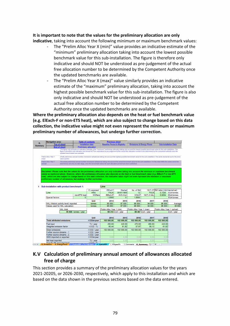
79
It is important to note that the values for the preliminary allocation are only indicative, taking into account the following minimum or maximum benchmark values:
- The “Prelim Alloc Year X (min)” value provides an indicative estimate of the “minimum” preliminary allocation taking into account the lowest possible benchmark value for this sub-installation. The figure is therefore only indicative and should NOT be understood as pre-judgement of the actual free allocation number to be determined by the Competent Authority once the updated benchmarks are available.
- The “Prelim Alloc Year X (max)” value similarly provides an indicative estimate of the “maximum” preliminary allocation, taking into account the highest possible benchmark value for this sub-installation. The figure is also only indicative and should NOT be understood as pre-judgement of the actual free allocation number to be determined by the Competent Authority once the updated benchmarks are available.
Where the preliminary allocation also depends on the heat or fuel benchmark value (e.g. ElExch-F or non-ETS heat), which are also subject to change based on this data collection, the indicative value might not even represent the minimum or maximum preliminary number of allowances, but undergo further correction.
K.V Calculation of preliminary annual amount of allowances allocated free of charge
This section provides a summary of the preliminary allocation values for the years 2021-20205, or 2026-2030, respectively, which apply to this installation and which are based on the data shown in the previous sections based on the data entered.

80
The results displayed here are indicative only. No warranty, either expressed or implied, is provided in relation to the accuracy, completeness or reliability of the result. No rights or entitlement to a certain amount of allowances can be derived from the result displayed in this template.

81
Annex A: Comparison with 2011 Guidance Document 3
The below table shows how the sections of the 2011 version of Guidance Document 3 correlate to the sections in the current, 2019 version, and where main topics are covered. Please note that the contents of corresponding sections in the different versions can be significantly changed as a result of new rules in the revised ETS Directive or the FAR regulation. ‘-‘ indicates that the topic was not included in the corresponding GD.
Content Section in Comments
2011 GD3
2019 GD3
Introduction 1 2019 GD3 refers to general introduction section in 2019 GD1
Status of the Guidance Documents -, in GD1
Background of the CIM Guidance Documents -, in GD1
Use of the Guidance documents -, in GD1
Additional guidance -, in GD1
Scope of this guidance document 1.1
Objective 2
Background to data collection 2.1
Link to NIMs baseline data template and other documents
2.2
Relevance of different sections for different installations
2.3 Table has been updated
General guidelines on the use of the template
- 2.4 Added in the 2019 version.
MS-specific parameters in NIMs baseline data template
3
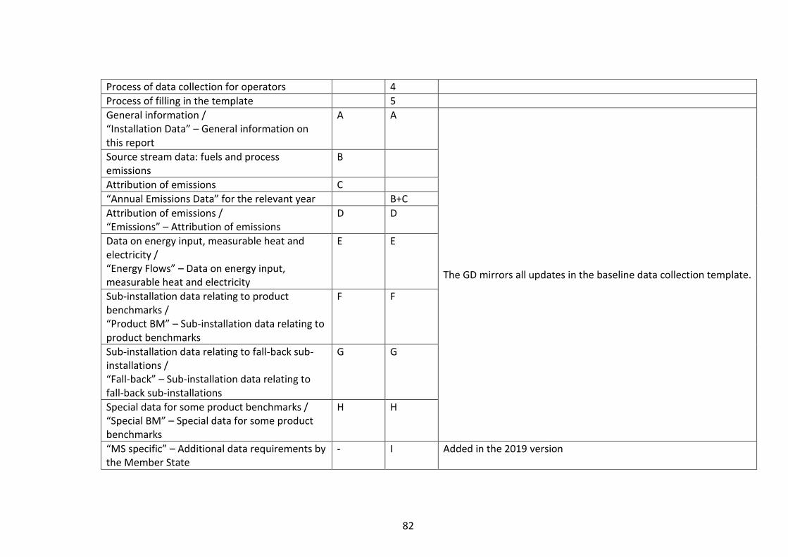
82
Process of data collection for operators 4
Process of filling in the template 5
General information / “Installation Data” – General information on this report
A A
The GD mirrors all updates in the baseline data collection template.
Source stream data: fuels and process emissions
B
Attribution of emissions C
“Annual Emissions Data” for the relevant year B+C
Attribution of emissions / “Emissions” – Attribution of emissions
D D
Data on energy input, measurable heat and electricity / “Energy Flows” – Data on energy input, measurable heat and electricity
E E
Sub-installation data relating to product benchmarks / “Product BM” – Sub-installation data relating to product benchmarks
F F
Sub-installation data relating to fall-back sub-installations / “Fall-back” – Sub-installation data relating to fall-back sub-installations
G G
Special data for some product benchmarks / “Special BM” – Special data for some product benchmarks
H H
“MS specific” – Additional data requirements by the Member State
- I Added in the 2019 version
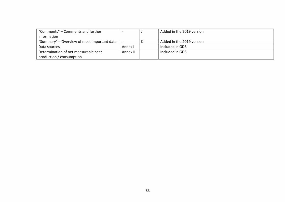
83
“Comments” – Comments and further information
- J Added in the 2019 version
“Summary” – Overview of most important data - K Added in the 2019 version
Data sources Annex I Included in GD5
Determination of net measurable heat production / consumption
Annex II Included in GD5