Data Center Design Summary - August 2014 · To ensure the compatibility of designs in the ... •...
42
Data Center Design Summary August 2014 Series
Transcript of Data Center Design Summary - August 2014 · To ensure the compatibility of designs in the ... •...

Data CenterDesign Summary
August 2014 Series
Table of Contents
Table of ContentsPreface ........................................................................................................................................1
Introduction .................................................................................................................................2
Business Overview ......................................................................................................................5Business Use Cases ................................................................................................................... 5
Use Case: Flexible Ethernet Network Foundation for Growth and Scale ................................. 5Use Case: Virtual Machine Mobility within the Data Center ..................................................... 6Use Case: Secure Access to Data Center Resources ............................................................ 6Use Case: Deploy Server Room LAN in Central and Remote Locations ................................. 6Use Case: Secure Server Room Resources with Cisco ASA .................................................. 6Use Case: Virtualize Server Hardware and Network Connectivity .......................................... 6Use Case: Centralize Server Configuration and Management ................................................ 6Use Case: Reduce Application Deployment Time ................................................................... 6Use Case: Simplify Network Management in the Data Center ................................................ 7Use Case: Increase Network Performance in the Hypervisor Environment ............................. 7
The Value of a Cohesive Data Center Strategy to an Organization ............................................. 7
Data Center Architecture .............................................................................................................8Data Center Foundation .......................................................................................................... 8Data Center Services ............................................................................................................. 8User Services ......................................................................................................................... 9
Data Center Design ..................................................................................................................... 9Physical Environment .............................................................................................................. 9Ethernet Infrastructure .......................................................................................................... 10Storage Infrastructure ............................................................................................................14Compute Connectivity ..........................................................................................................17Network Security ...................................................................................................................19
Server Room Design ................................................................................................................. 22Server Room Ethernet LAN ................................................................................................. 23Server Room Security ......................................................................................................... 23

Table of Contents
Unified Computing System Design .......................................................................................... 24Application Growth ............................................................................................................... 24Increasing Storage Requirements ......................................................................................... 25Managing Processing Resources ......................................................................................... 25Availability and Business Continuance .................................................................................. 25Computing Systems ............................................................................................................. 27Cisco UCS Manager ............................................................................................................. 27Cisco UCS Blade Server Chassis ......................................................................................... 27Cisco UCS Blade Server Network Connectivity .................................................................... 28Cisco UCS C-Series Rack-Mount Servers ........................................................................... 29Cisco UCS C-Series Network Connectivity .......................................................................... 30Third-Party Computing Systems .......................................................................................... 31Server Virtualization and Cisco UCS ..................................................................................... 31
Nexus 1000V and VMware Design............................................................................................ 31VMware Scalable Solutions .................................................................................................. 32Virtual Switching with Cisco Nexus 1000V ........................................................................... 33
Summary ...................................................................................................................................36
Glossary ....................................................................................................................................37
Preface August 2014 Series1
PrefaceCisco Validated Designs (CVDs) present systems that are based on common use cases or engineering priorities. CVDs incorporate a broad set of technologies, features, and applications that address customer needs. They incorporate a broad set of technologies, features, and applications to address customer needs. Cisco engineers have comprehensively tested and documented each CVD in order to ensure faster, more reliable, and fully predictable deployment.
This design summary provides information about the use cases covered in a series or set of related CVD guides and summarizes the Cisco products and technologies that solve the challenges presented by the use cases.
CVD Foundation SeriesThis CVD Foundation guide is a part of the August 2014 Series. As Cisco develops a CVD Foundation series, the guides themselves are tested together, in the same network lab. This approach assures that the guides in a series are fully compatible with one another. Each series describes a lab-validated, complete system.
The CVD Foundation series incorporates wired and wireless LAN, WAN, data center, security, and network management technologies. Using the CVD Foundation simplifies system integration, allowing you to select solutions that solve an organization’s problems—without worrying about the technical complexity.
To ensure the compatibility of designs in the CVD Foundation, you should use guides that belong to the same release. For the most recent CVD Foundation guides, please visit the CVD Foundation web site.
Comments and QuestionsIf you would like to comment on a guide or ask questions, please use the feedback form.
Introduction August 2014 Series2
IntroductionThe Cisco Validated Designs (CVDs) enterprise data center is a comprehensive architecture that accommodates your organization’s IT needs, from a server room to a data center, for organizations with up to 300 server ports. This out-of-the-box approach is easy to use, affordable, scalable, and flexible. The CVD enterprise data center architecture provides the ability for growing organizations to migrate from server room deployments to a scalable data center design.
This data center architecture incorporates Ethernet and storage network, computing resources, security, application resiliency, and virtualization tested together as a solution. This solution-level approach simplifies the system integration normally associated with multiple technologies, allowing you to select the modules that meet your organization’s requirements rather than worrying about matching components and interoperability.

Introduction August 2014 Series3
The following figure provides a high-level overview of the data center architecture.
Figure 1 - Data center design overview
22
16
Cisco ASA Firewalls
with IPS
Cisco UCSC-Series Servers
Cisco UCS Blade Servers, Chassis, and Fabric Interconnects
LAN Core
FCoE and iSCSIStorage Array
ExpandedCisco MDS 9100
Storage Fabric
Nexus 2200 SeriesFabric Extenders
Fibre ChannelStorage Array
Fibre ChannelStorage Array
SAN ASAN B
Nexus 5500 Layer 2/3 Ethernetand SAN Fabric
Third-partyRack Servers
SAN BSAN AEthernet
Fibre Channel
Fibre Channel over Ethernet
UCS Fabric Interconnect Link
UCS I/O and FEX Uplinks
DataCenter

Introduction August 2014 Series4
Cisco has designed, built, and tested this architecture to meet the following goals:
• Ease of deployment—A top requirement was to develop a design according to best-practice methodology that provides a fast and resilient deployment.
• Cost-effective—A requirement in the selection of products for the CVD enterprise server room and data center architecture was to meet the budget guidelines for a growing organization to scale from a server room with up to 25 servers, to a data center with up to 300 server ports supporting a mix of physical and virtual servers.
• Flexibility and scalability—As the company grows, so too must its infrastructure. Products selected need to have the ability to grow the network foundation and services in a modular manner.
• Resiliency and security—The data center foundation is designed with redundant devices and links to enhance reliability. Network services are layered on to protect critical data center resources from attacks or unplanned outages.
• Ease of management—Deployment and configuration guidance includes configuration examples of management by unique element managers or by a network management system.
Business Overview August 2014 Series5
Business OverviewAs organizations grow, they face many challenges related to information-processing capacity and the ability to keep up with the demands of their internal and external users. New organizations begin with a small group of servers to house basic resources like email, file sharing, database applications, and web services. Over time, the size of the applications and the number of applications drives increased processing and storage requirements and results in a growth explosion commonly referred to as “server sprawl.” Small organizations can use many of the same data center technologies that larger organizations use to manage growth and control operational and capital expenses. The challenge for organizations is determining how to absorb and deploy new technology with their existing IT staff and ensure that the design grows with the organization.
Organizations must address the following challenges as they look to grow their data center infrastructure:
• Supporting rapid application growth—Reduce the time necessary to expand existing applications or deploy new applications, often from months or days to hours.
• Managing growing data storage requirements—Keep up with application growth that drives the need to centralize data storage to control costs and improve the ability to back up critical information.
• Optimizing the investment in server processing resources—Reduce the cost of maintaining, operating, and deploying servers. Streamline and combine applications on a smaller number of physical servers.
• Reliably accessing information—Maintain application availability, which drives user productivity and requires a high availability foundation design.
• Securing the organization’s critical data—Protect the central repository of the organization’s most critical data from attacks and snooping.
• Controlling the cost of deploying a new data center—Use tested reference designs and avoid designing and building everything from scratch.
Business Use CasesServer virtualization technologies help to more fully utilize the organization’s investment in processing capacity, while still allowing each virtual machine to be viewed independently from a security, configuration, and troubleshooting perspective. Server virtualization and centralized storage technologies complement one another, allowing rapid deployment of new servers and reduced downtime in the event of server hardware failures. Virtual machines can be stored completely on the centralized storage system, which decouples the identity of the virtual machine from any single physical server. This allows the organization great flexibility when rolling out new applications or upgrading server hardware. In order to support the virtualization of computing resources in the data center, the underlying network must be able to provide a reliable, flexible, and secure transport.
The data center design guides address the following use cases.
Use Case: Flexible Ethernet Network Foundation for Growth and ScaleAs an organization outgrows the capacity of the basic server-room Ethernet stack of switches, it is important to be prepared for the ongoing transition of server connectivity from 1-Gigabit Ethernet attachment to 10-Gigabit Ethernet. Using a pair of switches to form a single-tier of switching, this design provides the ability to cleanly scale high speed server and appliance connectivity from a single equipment rack to multiple racks, connected back to a pair of data center core switches.
Business Overview August 2014 Series6
Use Case: Virtual Machine Mobility within the Data CenterThe hypervisor technology provides the ability to cluster many virtual machines into a domain where workloads can be orchestrated to move around the data center in order to provide resiliency and load balancing.
Use Case: Secure Access to Data Center ResourcesThe data center contains some of the organization’s most valuable assets. Customer and personnel records, financial data, email stores, and intellectual property must be maintained in a secure environment in order to assure confidentiality and availability.
Use Case: Deploy Server Room LAN in Central and Remote LocationsOrganizations often begin with application servers sitting under desks or in closets with switches—and perhaps some storage tapes for ad hoc backups stacked on top. As the organization grows and its reliance on data grows, so does the need to provide a more stable environment for its critical applications. Whether it is the fear of an outage delaying productivity, data loss that could harm the perception of an organization, or regulatory compliance, the IT person is forced to build a more suitable environment.
The server room represents the first move into a serious IT environment onsite with the business. An example environment will have controlled cooling and power, two to three equipment racks for application servers, supporting network connectivity, and a small backup system.
Use Case: Secure Server Room Resources with Cisco ASAWith communication and commerce in the world becoming increasingly Internet-based, network security quickly becomes a primary concern in a growing organization. Often organizations will begin by securing their Internet edge connection, considering the internal network a trusted entity. However, an Internet firewall is only one component of building security into the network infrastructure.
Frequently, threats to an organization’s data may come from within the internal network. This may come in the form of onsite vendors, contaminated employee laptops, or existing servers that have already become compromised and may be used as a platform to launch further attacks. With the centralized repository of the organization’s most critical data typically being the data center, security is no longer considered an optional component of a complete data center architecture plan.
Use Case: Virtualize Server Hardware and Network ConnectivitySome applications require enough processing and memory that you need to dedicate an entire server to running them, while others benefit from hypervisors to optimize workloads and storage. The key is to optimize your server environment for both requirements.
Use Case: Centralize Server Configuration and ManagementApplication servers for an organization are often placed in a variety of locations, posing an operational burden for IT management. The ability to centrally manage servers located in a data center or a remote site can reduce the time and expense required to manage an organization’s server population.
Use Case: Reduce Application Deployment TimeUtilize the VMware hypervisor to quickly deploy a new application on a portion of a server (or virtual machine). Virtualize the physical server and network connectivity components in order to optimize server deployment for hypervisor or single operating system requirements.

Business Overview August 2014 Series7
Use Case: Simplify Network Management in the Data CenterThe challenge in the virtualized data center is to reduce complexity while enabling the flexibility that virtualization provides. You can deploy a single switch fabric on physical and virtual switches.
Use Case: Increase Network Performance in the Hypervisor EnvironmentOptimize network throughput in VMware hypervisor environments by bypassing software-based switches and allowing virtual machines to connect directly to the data center fabric by using virtual machine fabric extension.
The Value of a Cohesive Data Center Strategy to an Organization
As your organization grows, you require a plan for how to grow the IT infrastructure to support user access to applications that support the business. Workforce productivity enhancements are built on the expectation of nonstop access to applications and resources that enable a user to do their job. Depending on the location of a user, many factors can influence the successful connectivity to an application that resides in the data center. However, the availability of the data center itself is core to overall reliability.
Planning, testing, and implementing various components and services in the data center on your own can pose a large challenge for organizations. By using the CVD enterprise data center design—which tests and validates the foundation infrastructure, security, application resilience, computing, and virtualization—you can reduce costs, risks, and operational issues, as well as increase deployment speed.
There are many ways an organization can benefit by deploying CVD enterprise data center architectures:
• Flexibility to address a variety of data center technologies and resiliency options
• Scalability provided by using a consistent method for data center connectivity based on the CVD enterprise campus architecture
• Reduced cost of deploying a standardized design based on Cisco-tested and supported best practices
• Summarized and simplified design choices so that IT workers with a CCNA certification or equivalent experience can deploy and operate the network
Using a modular approach to building your network with tested, interoperable designs allows you to reduce risks and operational issues and to increase deployment speed.

Data Center Architecture August 2014 Series8
Data Center ArchitectureIn the context of a building design, architecture means the art and science of designing and constructing buildings. In the context of a data center design, architecture refers to the design, structure, and behavior of the whole system—how the various components interact to communicate and process information for an application. These definitions support the broader process used to create the enterprise data center design covered in this summary guide.
The Cisco Validated Designs program follows a consistent design process of building a network based on layers of services. The CVD enterprise data center architecture consists of three primary modular layers with hierarchical interdependencies: data center foundation, data center services, and user services. The ultimate goal of the layers of the architecture is to support the user services that drive the organization’s success.
Figure 2 - CVD enterprise data center pyramid of service layers
21
96
UserServices
Data CenterServices
Data CenterFoundation
Voice,Email,
CRM, ERP
Security, Virtualization,
Application Resilience
Routing, Switching,Storage, Compute
Data Center FoundationSimilar to the foundation of a building, the primary building block of the data center is the foundation layer, upon which all other services rely. Whether it’s a server room Ethernet LAN or a formal data center, the foundation must be resilient, scalable, and flexible in order to support data center services that add value, performance, and reliability. The data center foundation provides the computing necessary to support the applications that process information and the seamless transport between servers, storage, and the end users who access the applications.
To the applications and users, the data center foundation works transparently when implemented correctly. The intelligent infrastructure of Ethernet and storage switches tied to servers and storage arrays make this all possible.
Data Center ServicesData center services are the next layer in the hierarchy. Like the customizable aspects of a building plan, they complement and customize the environment for the intended purpose. You may require large open spaces for a manufacturing floor, or high solid walls with controlled access for a secure environment. The consideration of these customizable services makes the structure more usable. Data center services allow you to customize the environment to a greater degree and enhance operation.
Data Center Architecture August 2014 Series9
Cisco data center services include:
• Firewalls and intrusion-prevention, in order to enhance the security of the applications and access to critical data.
• Application services such as load-balancing and service-monitoring, in order to enhance resilience.
Virtual switching extends the network control in a seamless manner from the foundation network into the hypervisor systems on servers, which increases control and lowers operational costs.
User ServicesUser services sit at the top of the pyramid and rely on the data center foundation and services in order to work. User services are those applications that allow a person to do their job and ultimately drive productivity for the organization. In the context of a building, this may be the elevator that takes you to your office floor, the lights in the office, or the message button on the phone that allows you to check messages. User services in the data center include email, order processing, and file sharing. Other applications in the data center that rely on the data center foundation and services—such as data base applications, modeling, and transaction processing—also sit at the top of the pyramid of services.
Data Center DesignThe following technology areas are covered within this reference architecture. Included within each chapter of this guide is a deeper and more comprehensive look at the technologies and features used in the overall design.
Physical EnvironmentThis data center design provides a resilient environment with redundant platforms and links; however, this cannot protect your data center from a complete failure resulting from a total loss of power or cooling. When designing your data center, you must consider how much power you will require, how you will provide backup power in the event of a loss of your power feed from your provider, and how long you will retain power in a backup power event. You also need to consider that servers, networking equipment, and appliances in your data center dissipate heat as they operate, which requires that you develop a cooling design in which you properly locate equipment racks and prevent hotspots.
PowerKnow what equipment will be installed in the area. You cannot plan electrical work if you do not know what equipment is going to be used. Some equipment requires standard 110V outlets that may already be available. Other equipment might require much more power.
Does the power need to be on all the time? In most cases where servers and storage are involved, the answer is yes. To prevent power outages, you need an uninterruptable power supply (UPS). During a power interruption, the UPS will switch over the current load to a set of internal or external batteries. Some UPSs are online, which means the power is filtered through the batteries all of the time; others are switchable, meaning they use batteries only during power loss. UPSs vary by how much load they can carry and for how long. Careful planning is required to make sure the correct UPS is purchased, installed, and managed properly. Most UPSs provide for remote monitoring and the ability to trigger a graceful server shutdown for critical servers if the UPS is going to run out of battery.

Data Center Architecture August 2014 Series10
CoolingWith power comes the inevitable conversion of power into heat. To put it simply: power in equals heat out. Planning for cooling of one or two servers and a switch with standard building air conditioning may work. For proper cooling, multiple servers and blade servers (along with storage, switches, and so on.) need more than building air conditioning. Be sure to at least plan with your facilities team what the options are for current and future cooling. Many options are available, including in-row cooling, overhead cooling, raised floor with underfloor cooling, and wall-mounted cooling.
Equipment RackingIt’s important to plan where to put the equipment. Proper placement and planning allow for easy growth. After you have evaluated power and cooling, you need to install racking or cabinets. Servers tend to be fairly deep and take up even more space with their network connections and power connections. Most servers will fit in a 42-inch deep cabinet, and deeper cabinets give more flexibility for cable and power management within the cabinet. Be aware of what rails are required by your servers. Most servers now come with rack mounts that use the square hole–style vertical cabinet rails. Not having the proper rails can mean that you have to use adapters or shelves, which makes managing servers and equipment difficult if not sometimes impossible without removing other equipment or sacrificing space. Data center racks should use the square rail mounting options in the cabinets. Cage nuts can be used to provide threaded mounts for routers, switches, shelves, and so on.
Physical Environment SummaryThe physical environmental requirements for a data center require careful planning in order to provide for efficient use of space, scalability, and ease of operational maintenance. For additional information on data center power, cooling, and equipment racking, contact Cisco partners in the area of data center environmental products such as Panduit and APC.
Ethernet InfrastructureThe foundation of the Ethernet network in this data center design is a resilient pair of Cisco Nexus 5500UP Series switches. These switches offer the ideal platform for building a scalable, high-performance data center supporting both 10-Gigabit and 1-Gigabit Ethernet attached servers. The data center is designed to allow easy migration of servers and services from your original server room to a data center that can scale with your organization’s growth.
This data center design leverages many advanced features of the Cisco Nexus 5500UP Series switch family to provide a central Layer 2 and Layer 3 switching fabric for the data center environment:
• The Layer 3 routing table can accommodate up to 8000 IPv4 routes.
• The Layer 3 engine supports up to 8000 adjacencies or MAC addresses for the Layer 2 domain.
• The solution provides for up to 1000 IP Multicast groups when operating in the recommended virtual port channel (vPC) mode.

Data Center Architecture August 2014 Series11
The Layer 3 data center core connects to the Layer 3 LAN core designed in the Campus Wired LAN Technology Design Guide, as shown in the following figure.
Figure 3 - Data center core to LAN core connectivity
Data Center Serversand Services
21
98LAN Internet
and DMZWAN
DataCenterCore
SeparateChange Control
Domains
LAN Core
The results of using Layer 3 to interconnect the two core layers are:
• A resilient Layer 3 interconnect with rapid failover.
• The two core networks have a logical separation of change control.
• The LAN core provides a scalable interconnect for LAN, WAN, and Internet Edge.
• The data center core provides interconnect for all data center servers and services.
• Intra-data center Layer 2 and Layer 3 traffic flows between servers and appliances are switched locally on the data center core.
• The data center has a logical separation point for moving to an offsite location while still providing core services without redesign.

Data Center Architecture August 2014 Series12
Resilient Data Center CoreThe data center needs to provide a topology in which any data center VLAN can be extended to any server in the environment in order to accommodate new installations without disruption. The topology must also allow moving a server load to any other physical server in the data center. Traditional Layer 2 designs with LAN switches rely on Spanning Tree Protocol (STP) in order to detect and block loops created when a VLAN is extended to multiple access layer switches. STP blocks links to prevent looping, as shown in the figure below.
Figure 4 - Traditional design with spanning tree blocked links
20
52
Spanning TreeBlocked Link
Spanning TreeRoot Switch
VLAN 148 VLAN 148
You can configure vPC by using the Cisco Nexus 5500UP Series switch pair that provides the central Ethernet switching fabric for the data center. The vPC feature allows links that are physically connected to two different Cisco Nexus switches to appear to a third downstream device to be coming from a single device, as part of a single Ethernet port channel. The third device can be a server, switch, or any other device or appliance that supports IEEE 802.3ad port channels. This capability allows the two data center core switches to build resilient, loop-free Layer 2 topologies that forward on all connected links instead of requiring STP blocking for loop prevention.
Cisco NX-OS Software vPC used in the data center design and Cisco Catalyst Virtual Switching System (VSS) used in LAN deployments are similar technologies in that they allow the creation of Layer 2 port channels that span two switches. A vPC consists of two vPC peer switches connected by a peer link. Of the vPC peers, one is primary and one is secondary. The system formed by the switches is referred to as a vPC domain.
Figure 5 - Cisco NX-OS vPC design
22
17
Layer 2EtherChannels
vPC Peer Keepalive
vPC Peer Link
VLAN 148 VLAN 148
vPCDomain
Ethernet Fabric ExtensionThe Cisco Nexus 2000 Series Fabric Extender (FEX) delivers a cost-effective and highly scalable 1-Gigabit Ethernet and 10-Gigabit Ethernet environment in your data center. Fabric extension allows you to aggregate a group of physical switch ports at the top of each server rack, without needing to manage these ports as a separate logical switch. The Cisco FEX behaves as a remote line card to the Cisco Nexus 5500UP switches.
Data Center Architecture August 2014 Series13
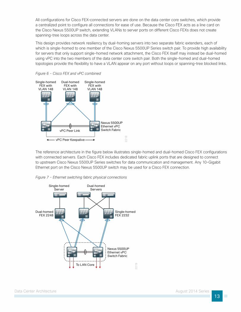
All configurations for Cisco FEX–connected servers are done on the data center core switches, which provide a centralized point to configure all connections for ease of use. Because the Cisco FEX acts as a line card on the Cisco Nexus 5500UP switch, extending VLANs to server ports on different Cisco FEXs does not create spanning-tree loops across the data center.
This design provides network resiliency by dual-homing servers into two separate fabric extenders, each of which is single-homed to one member of the Cisco Nexus 5500UP Series switch pair. To provide high availability for servers that only support single-homed network attachment, the Cisco FEX itself may instead be dual-homed using vPC into the two members of the data center core switch pair. Both the single-homed and dual-homed topologies provide the flexibility to have a VLAN appear on any port without loops or spanning-tree blocked links.
Figure 6 - Cisco FEX and vPC combined
22
18
vPC Peer Keepalive
vPC Peer Link
Single-homedFEX with
VLAN 148
Dual-homedFEX with
VLAN 148
Single-homedFEX with
VLAN 148
Nexus 5500UPEthernet vPCSwitch Fabric
The reference architecture in the figure below illustrates single-homed and dual-homed Cisco FEX configurations with connected servers. Each Cisco FEX includes dedicated fabric uplink ports that are designed to connect to upstream Cisco Nexus 5500UP Series switches for data communication and management. Any 10-Gigabit Ethernet port on the Cisco Nexus 5500UP switch may be used for a Cisco FEX connection.
Figure 7 - Ethernet switching fabric physical connections
22
19To LAN Core
Dual-homedFEX 2248
Single-homedFEX 2232
Dual-homedServers
Single-homedServer
Nexus 5500UPEthernet vPCSwitch Fabric

Data Center Architecture August 2014 Series14
Quality of ServiceTo support the lossless data requirement of fibre channel over Ethernet (FCoE) on the same links as IP traffic, the Nexus 5500 switches and the Nexus 2000 fabric extenders as a system implement an approach that uses Quality of Service (QoS) with a data center focus. Much of the QoS for classification and marking in the system is constructed through the use of the IEEE 802.1Q priority code point, also known as class of service (CoS) bits in the header of the Layer 2 frame from hosts supporting FCoE and other trunked devices. As IP traffic arrives at an Ethernet port on the Cisco Nexus 5500 Series switch, it can also be classified at Layer 3 by differentiated services code point (DSCP) bits and IP access control lists (ACLs).
The traffic classifications are used for mapping traffic into one of six hardware queues, each appropriately configured for desired traffic handling. One queue is predefined for default traffic treatment, while one hardware queue is assigned for use by lossless FCoE traffic. The remaining four queues are available for use to support queuing of multimedia and data center traffic. For example, a priority queue will be defined for jitter-intolerant multimedia services in the data center.
Lacking the guarantee that all non-FCoE devices in the data center can generate an appropriate CoS marking required for application of QoS policy at ingress to a FEX, this data center design takes the following QoS approach:
• FCoE traffic, as determined by Data Center Bridging Exchange (DCBX) negotiation with hosts, is given priority and lossless treatment end-to-end within the data center.
• Non-FCoE traffic without CoS classification for devices connected to a FEX is given default treatment over available links on ingress toward the Cisco Nexus 5500 switch, with suitable aggregated link bandwidth available to mitigate oversubscription situations. Traffic in the reverse direction toward the FEX is handled by the QoS egress policies on the Cisco Nexus 5500 switch.
• Classification by DSCP is configured at the port level and applied to IP traffic on ingress to the Cisco Nexus 5500 switch, either directly or after traversing a FEX connection. This classification is used to map traffic into the default queue or into one of the four non-FCoE internal queues to offer a suitable QoS per-hop behavior.
• To ensure consistent policy treatment for traffic directed through the Layer 3 engine, a CoS marking is also applied per Cisco Nexus 5500 internal queue. The CoS marking is used for classification of traffic ingress to the Layer 3 engine, allowing application of system queuing policies.
Non-FCoE devices requiring DSCP-based classification with guaranteed queuing treatment can be connected directly to the Cisco Nexus 5500 switch, versus taking the default uplink treatment when connected to a Cisco FEX port.
Storage InfrastructureThere is a constant demand for more storage. Storage for servers can be physically attached to the server or connected over a network. Direct attached storage (DAS) is physically attached to a single server and is difficult to use efficiently because it can only be used by the host attached to it. Storage area networks (SANs) allow multiple servers to share a pool of storage over an FC or Ethernet network. This capability allows storage administrators to easily expand capacity for servers that support data-intensive applications. The CVD enterprise data center design allows you to deploy Ethernet-based storage access, FC-based storage access, or both.
Most organizations have applications for multiple storage access technologies, such as:
• FC, for the high performance database.
• Production servers and network attached storage (NAS), for the high performance database.

Data Center Architecture August 2014 Series15
The data center core Cisco Nexus 5500UP switches that are used as the foundation of the network feature universal ports, which allow a port to transport 10 Gigabit Ethernet and FCoE on a port or native FC.
Figure 8 - Cisco Nexus 5500 with universal port
22
04
Nexus 5500UP Layer 2/3 Switch
and Storage Fabric
FCoE-attachedStorage
Array
Fibre Channel-attached
Storage Array
iSCSI or NASStorage
Array
Ethernet
Fibre Channel
Fibre Channel over Ethernet
Data Center Servers
This universal port capability provides the flexibility to support multiple SAN technologies on a single platform, thus reducing costs and operational complexity.
IP-based Storage OptionsMany storage systems provide the option for access using IP over the Ethernet network. This approach allows a growing organization to gain the advantages of centralized storage without needing to deploy and administer a separate Fibre Channel network. Options for IP-based storage connectivity include Internet small computer system interface (iSCSI) and NAS.
iSCSI is a protocol that enables servers to connect to storage over an IP connection and is a lower-cost alternative to Fibre Channel. iSCSI services on the server must contend for CPU and bandwidth along with other network applications, so you need to ensure that the processing requirements and performance are suitable for a specific application. iSCSI has become a storage technology that is supported by most server, storage, and application vendors. iSCSI provides block-level storage access to raw disk resources, similar to Fibre Channel. Network interface cards (NICs) also can provide support to offload iSCSI to a separate processor to increase performance.
NAS is a general term used to refer to a group of common file access protocols. The most common implementations use common Internet file system (CIFS) or network file server (NFS). CIFS originated in the Microsoft network environment and is a common desktop file-sharing protocol. NFS is a multi-platform protocol that originated in the UNIX environment and can be used for shared hypervisor storage. Both NAS protocols provide file-level access to shared storage resources.
Most organizations will have applications for multiple storage access technologies—for example, Fibre Channel for the high performance database and production servers and NAS for desktop storage access.
Data Center Architecture August 2014 Series16
Fibre Channel StorageFibre Channel allows servers to connect to storage across a fiber-optic network, across a data center, or even across a WAN by using Fibre Channel over IP. Multiple servers can share a single storage array.
This data center design uses the Cisco Nexus 5500UP series switches as the core that provides Fibre Channel and FCoE SAN switching. The Cisco Nexus 5500UP offers the density required for collapsed Fibre Channel connectivity requirements by supporting both Fibre Channel and FCoE servers and storage arrays. This is ideal for a larger SAN fabric with up to 48 Fibre Channel ports, providing 48 line-rate 8-Gbps Fibre Channel ports and cost-effective scalability. The Cisco MDS family of Multilayer SAN Fabric Switches also offers options like hardware-based encryption services, tape acceleration, and Fibre Channel over IP for longer distance SAN extension.
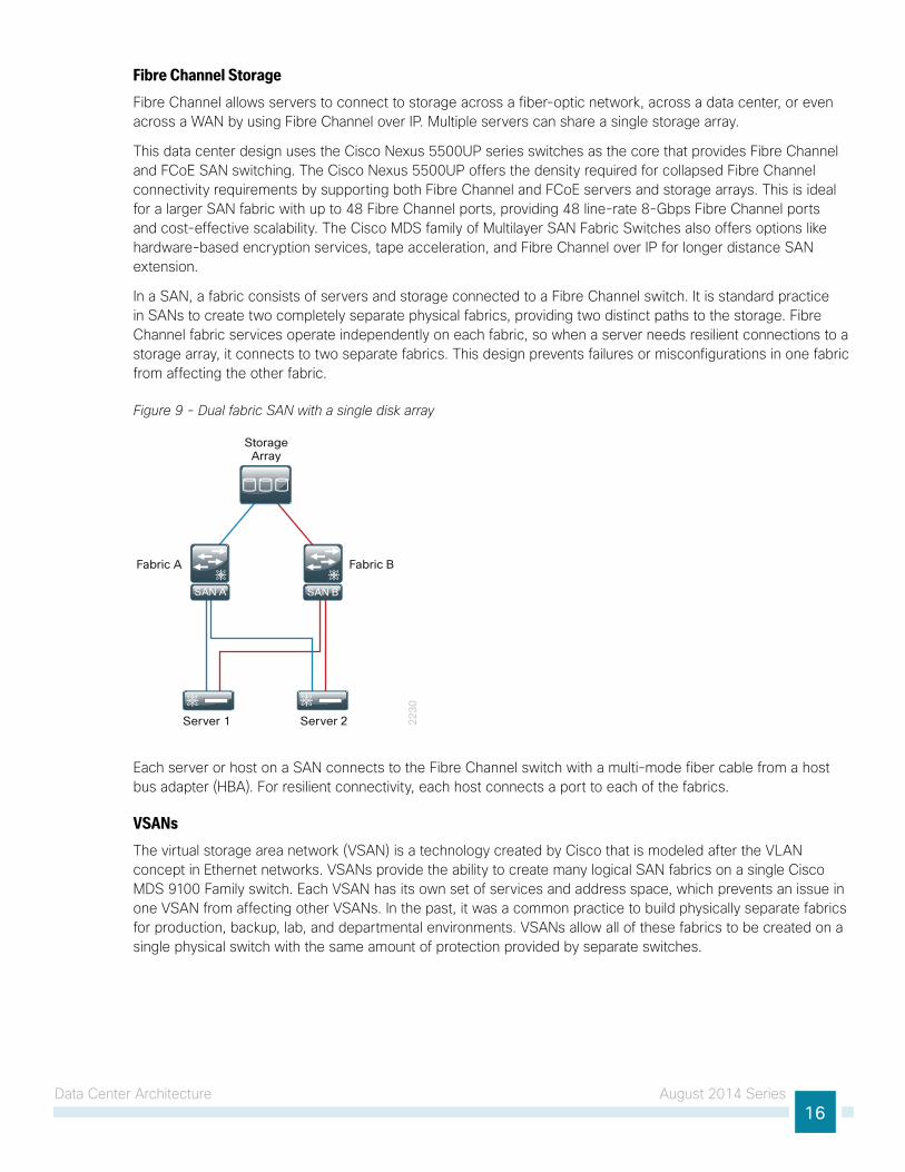
In a SAN, a fabric consists of servers and storage connected to a Fibre Channel switch. It is standard practice in SANs to create two completely separate physical fabrics, providing two distinct paths to the storage. Fibre Channel fabric services operate independently on each fabric, so when a server needs resilient connections to a storage array, it connects to two separate fabrics. This design prevents failures or misconfigurations in one fabric from affecting the other fabric.
Figure 9 - Dual fabric SAN with a single disk array 2
23
0
Server 1 Server 2
StorageArray
Fabric A Fabric B
SAN BSAN BSAN A
Each server or host on a SAN connects to the Fibre Channel switch with a multi-mode fiber cable from a host bus adapter (HBA). For resilient connectivity, each host connects a port to each of the fabrics.
VSANsThe virtual storage area network (VSAN) is a technology created by Cisco that is modeled after the VLAN concept in Ethernet networks. VSANs provide the ability to create many logical SAN fabrics on a single Cisco MDS 9100 Family switch. Each VSAN has its own set of services and address space, which prevents an issue in one VSAN from affecting other VSANs. In the past, it was a common practice to build physically separate fabrics for production, backup, lab, and departmental environments. VSANs allow all of these fabrics to be created on a single physical switch with the same amount of protection provided by separate switches.
Data Center Architecture August 2014 Series17
Zoning The terms target and initiator will be used throughout this section. Targets are disk or tape devices. Initiators are servers or devices that initiate access to disk or tape.
Zoning provides a means of restricting visibility and connectivity among devices connected to a SAN. The use of zones allows an administrator to control which initiators can see which targets. It is a service that is common throughout the fabric, and any changes to a zoning configuration are disruptive to the entire connected fabric.
Compute Connectivity Organizations frequently need to optimize the use of the investment in server resources so that the organization can add new applications while controlling costs as they move from a small server room environment into a data center scale environment. A data center foundation design must consider the computing resources as well as the network and storage transport to ensure an optimal design.
Scaling a data center with conventional servers, networking equipment, and storage resources can pose a significant challenge to a growing organization. Multiple hardware platforms and technologies must be integrated to deliver the expected levels of performance and availability to application end users. These components in the data center also need to be managed and maintained, typically with a diverse set of management tools with different interfaces and approaches.
Server virtualization offers the capability to run multiple application servers on a common hardware platform, allowing an organization to focus on maximizing the application capability of the data center while minimizing costs. Increased capability and reduced costs are realized through multiple aspects:
• Multiple applications can be combined in a single hardware chassis, reducing the number of boxes that must be accommodated in data-center space.
• Cable management is simplified, due to fewer required cable runs and greater flexibility in allocating network connectivity to hosts on an as-needed basis/
• Resiliency and application portability are improved. Hypervisors allow workload resiliency and load-sharing across multiple platforms, even in geographically dispersed locations.
• Applications are deployed on standardized hardware platforms, which reduce platform-management consoles and minimizes hardware spare stock challenges.
• Minimized box count reduces power and cooling requirements, because there are fewer lightly loaded boxes idling away expensive wattage.
Using hypervisor technologies (to virtualize server platforms and handle multiple operating systems and applications) allows the organization to lower capital and operating costs by collapsing more applications onto fewer physical servers. The hypervisor technology also provides the ability to cluster many virtual machines into a domain where workloads can be orchestrated to move around the data center. This provides resiliency and load balancing and allows new applications to be deployed in hours, versus days or weeks.
The ability to move virtual machines or application loads from one server to the next, whether the server is a blade server in a chassis-based system or a standalone rack-mount server, requires the network to be flexible and scalable, allowing any VLAN to appear anywhere in the data center. Cisco vPC and Cisco FEX technologies are used extensively in this data center design in order to provide flexible Ethernet connectivity to VLANs distributed across the data center in a scalable and resilient manner.
Data Center Architecture August 2014 Series18
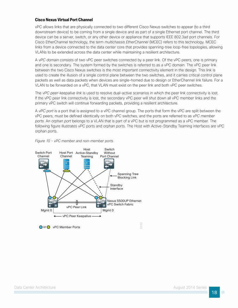
Cisco Nexus Virtual Port ChannelvPC allows links that are physically connected to two different Cisco Nexus switches to appear (to a third downstream device) to be coming from a single device and as part of a single Ethernet port channel. The third device can be a server, switch, or any other device or appliance that supports IEEE 802.3ad port channels. For Cisco EtherChannel technology, the term multichassis EtherChannel (MCEC) refers to this technology. MCEC links from a device connected to the data center core that provides spanning-tree loop-free topologies, allowing VLANs to be extended across the data center while maintaining a resilient architecture.
A vPC domain consists of two vPC peer switches connected by a peer link. Of the vPC peers, one is primary and one is secondary. The system formed by the switches is referred to as a vPC domain. The vPC peer link between the two Cisco Nexus switches is the most important connectivity element in the design. This link is used to create the illusion of a single control plane between the two switches, and it carries critical control plane packets as well as data packets when devices are single-homed due to design or EtherChannel link failure. For a VLAN to be forwarded on a vPC, that VLAN must exist on the peer link and both vPC peer switches.
The vPC peer-keepalive link is used to resolve dual-active scenarios in which the peer link connectivity is lost. If the vPC peer link connectivity is lost, the secondary vPC peer will shut down all vPC member links and the primary vPC switch will continue forwarding packets, providing a resilient architecture.
A vPC port is a port that is assigned to a vPC channel group. The ports that form the vPC are split between the vPC peers, must be defined identically on both vPC switches, and the ports are referred to as vPC member ports. An orphan port belongs to a VLAN that is part of a vPC but is not programmed as a vPC member. The following figure illustrates vPC ports and orphan ports. The Host with Active-Standby Teaming interfaces are vPC orphan ports.
Figure 10 - vPC member and non-member ports2
23
3
vPC Peer Keepalive
vPC Peer Link
vPC Member Portsor
Switch PortChannel
Host PortChannel
HostActive-Standby
Teaming
SwitchWithout
Port Channel
Nexus 5500UP EthernetvPC Switch Fabric
Mgmt 0Mgmt 0
Spanning TreeBlocking Link
StandbyInterface
Data Center Architecture August 2014 Series19
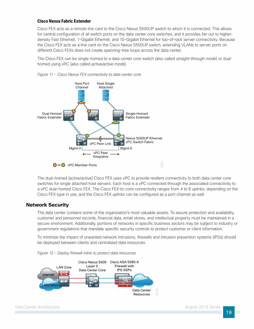
Cisco Nexus Fabric ExtenderCisco FEX acts as a remote line card to the Cisco Nexus 5500UP switch to which it is connected. This allows for central configuration of all switch ports on the data center core switches, and it provides fan out to higher-density Fast Ethernet, 1-Gigabit Ethernet, and 10-Gigabit Ethernet for top-of-rack server connectivity. Because the Cisco FEX acts as a line card on the Cisco Nexus 5500UP switch, extending VLANs to server ports on different Cisco FEXs does not create spanning-tree loops across the data center.
The Cisco FEX can be single-homed to a data center core switch (also called straight-through mode) or dual-homed using vPC (also called active/active mode).
Figure 11 - Cisco Nexus FEX connectivity to data center core
22
34
vPC PeerKeepalive
vPC Peer LinkMgmt 0 Mgmt 0
vPC Member Portsor
Dual-HomedFabric Extender
Single-HomedFabric Extender
Host PortChannel
Host SingleAttached
Nexus 5500UP EthernetvPC Switch Fabric
The dual-homed (active/active) Cisco FEX uses vPC to provide resilient connectivity to both data center core switches for single attached host servers. Each host is a vPC connected through the associated connectivity to a vPC dual-homed Cisco FEX. The Cisco FEX–to-core connectivity ranges from 4 to 8 uplinks, depending on the Cisco FEX type in use, and the Cisco FEX uplinks can be configured as a port channel as well.
Network SecurityThe data center contains some of the organization’s most valuable assets. To assure protection and availability, customer and personnel records, financial data, email stores, and intellectual property must be maintained in a secure environment. Additionally, portions of networks in specific business sectors may be subject to industry or government regulations that mandate specific security controls to protect customer or client information.
To minimize the impact of unwanted network intrusions, firewalls and intrusion prevention systems (IPSs) should be deployed between clients and centralized data resources.
Figure 12 - Deploy firewall inline to protect data resources
22
10
Cisco ASA 5585-XFirewall with
IPS SSPsLAN Core
Cisco Nexus 5500Layer 3
Data Center Core
LAN/WAN
Internet
Data CenterResources
Data Center Architecture August 2014 Series20
Because everything else outside the protected VLANs hosting the data center resources can be a threat, the security policy associated with protecting those resources has to include the following potential threat vectors:
• Internet
• Remote access and teleworker VPN hosts
• Remote office/branch networks
• Business partner connections
• Campus networks
• Unprotected data center networks
• Other protected data center networks
The data center IPSs monitor for and mitigate potential malicious activity that is contained within traffic allowed by the security policy defined on the Cisco Adaptive Security Appliances (ASA). The IPS sensors can be deployed in promiscuous intrusion detection system (IDS) mode so that they only monitor and alert for abnormal traffic. The IPS modules can be deployed inline in IPS mode to fully engage their intrusion prevention capabilities, wherein they will block malicious traffic before it reaches its destination. The choice to have the sensor drop traffic (or not) is influenced by several factors: risk tolerance for having a security incident, risk aversion for inadvertently dropping valid traffic, and other possibly externally driven reasons like compliance requirements for IPS. The ability to run in IDS mode or IPS is highly configurable, allowing the maximum flexibility in meeting a specific security policy.
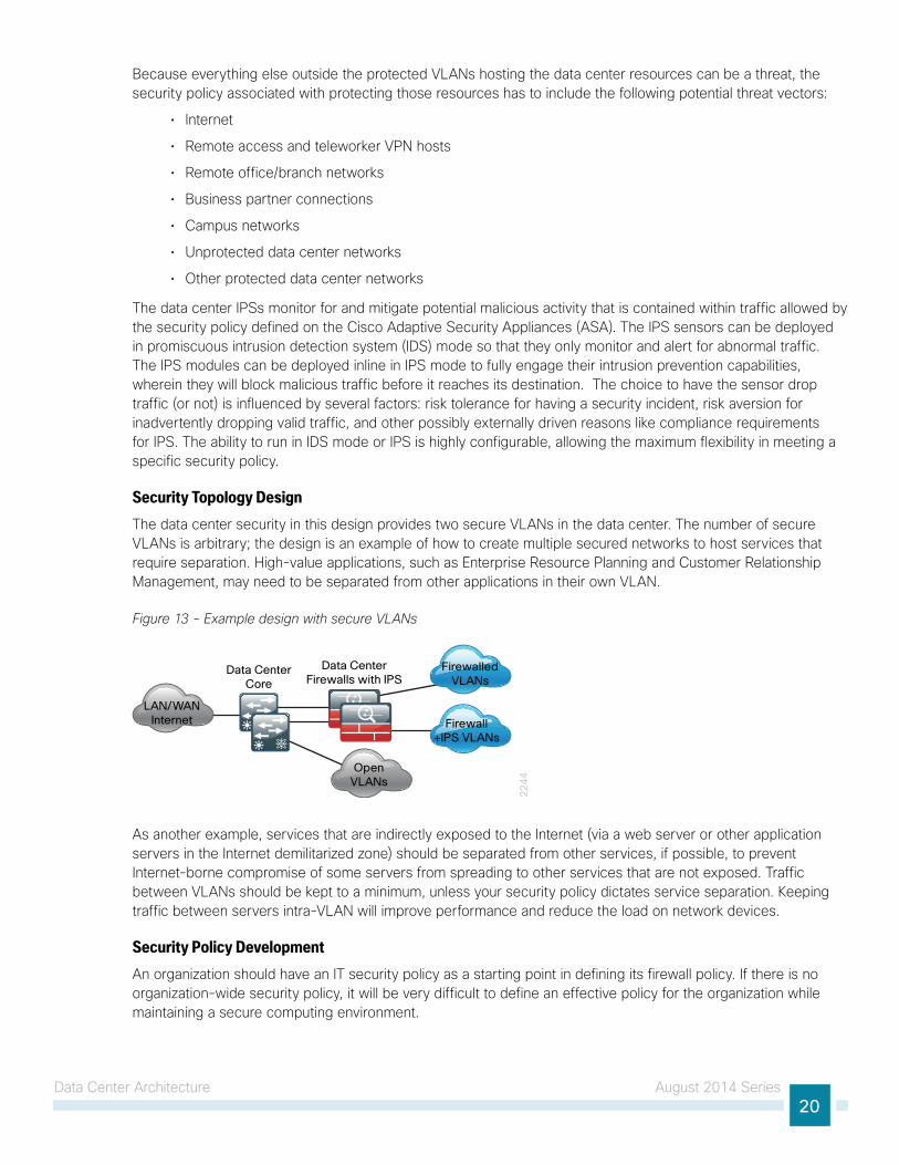
Security Topology Design The data center security in this design provides two secure VLANs in the data center. The number of secure VLANs is arbitrary; the design is an example of how to create multiple secured networks to host services that require separation. High-value applications, such as Enterprise Resource Planning and Customer Relationship Management, may need to be separated from other applications in their own VLAN.
Figure 13 - Example design with secure VLANs
22
44
LAN/WANInternet
Data CenterFirewalls with IPS
Data CenterCore
FirewalledVLANs
Firewall+IPS VLANs
OpenVLANs
As another example, services that are indirectly exposed to the Internet (via a web server or other application servers in the Internet demilitarized zone) should be separated from other services, if possible, to prevent Internet-borne compromise of some servers from spreading to other services that are not exposed. Traffic between VLANs should be kept to a minimum, unless your security policy dictates service separation. Keeping traffic between servers intra-VLAN will improve performance and reduce the load on network devices.
Security Policy Development An organization should have an IT security policy as a starting point in defining its firewall policy. If there is no organization-wide security policy, it will be very difficult to define an effective policy for the organization while maintaining a secure computing environment.

Data Center Architecture August 2014 Series21
To effectively deploy security between the various functional segments of a business’s network, you should seek the highest level of detail possible regarding the expected network behaviors. If you have greater detail of the expectations, you will be better positioned to define a security policy that enables a business’s application traffic and performance requirements while optimizing security.
Network security policies can be broken down into two basic categories: whitelist policies and blacklist policies. A whitelist policy offers a higher implicit security posture, blocking all traffic except that which must be allowed (at a sufficiently granular level) to enable applications. Whitelist policies are generally better positioned to meet regulatory requirements because only traffic that must be allowed to conduct business is allowed. Other traffic is blocked and does not need to be monitored to assure that unwanted activity is not occurring. This reduces the volume of data that will be forwarded to an IDS or IPS and also minimizes the number of log entries that must be reviewed in the event of an intrusion or data loss.
Figure 14 - Whitelist policy example
30
20
Xterm
FTP
Microsoft Data
SQL
DNS/HTTP/HTTPS
SNMP
MSRPC
Bypass
Other Data
Inversely, a blacklist policy only denies traffic that specifically poses the greatest risk to centralized data resources. A blacklist policy is simpler to maintain and less likely to interfere with network applications. A whitelist policy is the best-practice option if you have the opportunity to examine the network’s requirements and adjust the policy to avoid interfering with desired network activity.
Figure 15 - Blacklist policy example
30
19
Telnet
SNMP
Other Data
Cisco ASA firewalls implicitly end access lists with a deny-all rule. Blacklist policies include an explicit rule—prior to the implicit deny-all rule—that allows any traffic that is not explicitly allowed or denied.

Data Center Architecture August 2014 Series22
Server Room DesignThe server room design provides a growing organization its first formal foundation for centralizing up to 24 physical servers in a secure and resilient environment. It can also be used to provide a server room deployment for a regional site or in-country location for a larger organization. The following figure illustrates typical server room deployments.
Figure 16 - Typical server room deployment scenarios
30
22
DistributionSwitch
Wireless LANController
DistributionSwitch
Wireless LANController
Headquarters
Regional Site
CollapsedLAN Core
LAN Access
Server Room
Server Room
LAN
WANRouters
WAN
Routers
Internet
Internet EdgeFirewalls
Firewalls
Server RoomFirewalls
Servers
Switch Stack
Server RoomFirewalls
Servers
Client AccessSwitches
Client AccessSwitches
Switch Stack

Data Center Architecture August 2014 Series23
The design shows how to cleanly integrate network security capabilities such as firewall and intrusion prevention, while protecting areas of the network housing critical server and storage resources. The architecture provides the flexibility to secure specific portions of the server room or insert firewall capability between tiers of a multi-tier application, according to the security policy agreed upon by the organization.
Server Room Ethernet LAN The server room switches provide network connectivity for servers and appliances that offer network and user services to a variety of devices in the network. The server room design has two product lines to choose from: Cisco Catalyst 3850 Series and Cisco Catalyst 3650 Series switches. Cisco Catalyst 3850 Series offers flexible port density and server port connection speeds from 10-Mb Ethernet to 1-Gigabit Ethernet. With a Cisco Catalyst 3850 Series switch stack, you can build in fault tolerance by dual-homing servers to the server room and dual-homing the server room to the LAN distribution layer with redundant Gigabit Ethernet or 10-Gigabit Ethernet links in an EtherChannel. Cisco Catalyst 3850 Series provides platform resilience when stacked through Cisco StackWise480, which allows the control plane for the server room Ethernet switches to reside on either of the Catalyst 3850 Series switches and fail over in the event of a failure. Cisco StackPower on the Catalyst 3850 Series switch provides the ability to spread the power load over multiple power supplies in each chassis for diversity and resilience. The Cisco Catalyst 3650 Series switch offers a lower-cost option for applications where Ethernet LAN switch resiliency is not a priority.
Figure 17 - Resilience in the server room design
30
13
ServersSwitchStack
DistributionSwitch
Both the server room and the client LAN access methods connect devices to the network; the difference between the two methods that changes the switch model is the requirement in the LAN access for power over Ethernet (PoE). Although PoE-capable devices are not typical in the server room, using PoE-capable switches offers a benefit worth considering: the minor initial cost savings of a non-PoE switch may not be worth the benefits of using the same switch across multiple modules of your local LAN. Although configurations differ between LAN access switches and server room switches, the ability to use a single switch type between multiple modules can lower operational costs by allowing for simpler sparing and management, as well as provide a better chance of reuse as the organization grows.
Server Room Security Within the design, there are many requirements and opportunities to include or improve security. At the headquarters, there is a layer of security to protect the business information assets. These devices help provide direct and indirect protection against potential threats. The first product in the server room security perimeter is Cisco ASA 5500-X Series Midrange. Cisco ASA 5500-X Series is a next-generation multifunction appliance providing multi-gigabit firewall capability and intrusion prevention or intrusion detection services in a compact 1 rack-unit form-factor. Cisco ASA 5500-X Series runs the same base firewall and IPS software as the ASA 5500 Series, making transition and operational support easy for existing ASA customers.
Data Center Architecture August 2014 Series24
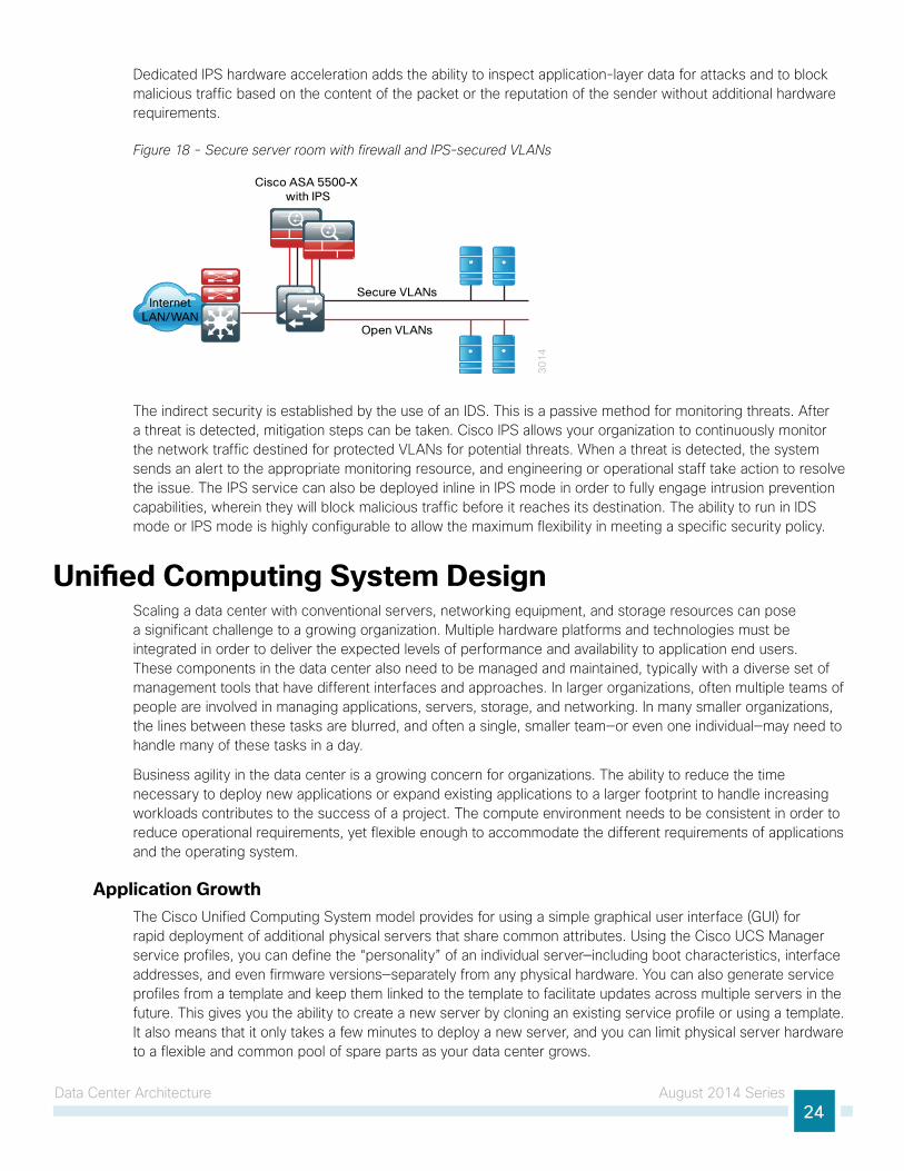
Dedicated IPS hardware acceleration adds the ability to inspect application-layer data for attacks and to block malicious traffic based on the content of the packet or the reputation of the sender without additional hardware requirements.
Figure 18 - Secure server room with firewall and IPS-secured VLANs
30
14
Secure VLANs
Open VLANs
Cisco ASA 5500-X with IPS
InternetLAN/WAN
The indirect security is established by the use of an IDS. This is a passive method for monitoring threats. After a threat is detected, mitigation steps can be taken. Cisco IPS allows your organization to continuously monitor the network traffic destined for protected VLANs for potential threats. When a threat is detected, the system sends an alert to the appropriate monitoring resource, and engineering or operational staff take action to resolve the issue. The IPS service can also be deployed inline in IPS mode in order to fully engage intrusion prevention capabilities, wherein they will block malicious traffic before it reaches its destination. The ability to run in IDS mode or IPS mode is highly configurable to allow the maximum flexibility in meeting a specific security policy.
Unified Computing System Design Scaling a data center with conventional servers, networking equipment, and storage resources can pose a significant challenge to a growing organization. Multiple hardware platforms and technologies must be integrated in order to deliver the expected levels of performance and availability to application end users. These components in the data center also need to be managed and maintained, typically with a diverse set of management tools that have different interfaces and approaches. In larger organizations, often multiple teams of people are involved in managing applications, servers, storage, and networking. In many smaller organizations, the lines between these tasks are blurred, and often a single, smaller team—or even one individual—may need to handle many of these tasks in a day.
Business agility in the data center is a growing concern for organizations. The ability to reduce the time necessary to deploy new applications or expand existing applications to a larger footprint to handle increasing workloads contributes to the success of a project. The compute environment needs to be consistent in order to reduce operational requirements, yet flexible enough to accommodate the different requirements of applications and the operating system.
Application GrowthThe Cisco Unified Computing System model provides for using a simple graphical user interface (GUI) for rapid deployment of additional physical servers that share common attributes. Using the Cisco UCS Manager service profiles, you can define the “personality” of an individual server—including boot characteristics, interface addresses, and even firmware versions—separately from any physical hardware. You can also generate service profiles from a template and keep them linked to the template to facilitate updates across multiple servers in the future. This gives you the ability to create a new server by cloning an existing service profile or using a template. It also means that it only takes a few minutes to deploy a new server, and you can limit physical server hardware to a flexible and common pool of spare parts as your data center grows.
Data Center Architecture August 2014 Series25
Increasing Storage RequirementsThe most efficient way to manage the investment in additional storage capacity is to move to a centralized storage model. The Cisco Unified Computing System model decouples the computing functions of the server farm from the storage systems, which provides greater flexibility for system growth and migration. System storage and boot disk are accessible from either the local disk that is available on each server or through access to centralized storage located on the Ethernet IP network or Fibre Channel or Fibre Channel over Ethernet SAN.
Managing Processing ResourcesSome applications require enough processing and memory that you might decide to dedicate an entire server or even a cluster of servers to support the workload. Other applications may start out on a single server where the processor and memory are underutilized, resulting in excess or wasted resources. In the case where applications need a separate operating environment but not an entire server for processing and memory resources, server virtualization is the key to combining applications and optimizing resources. Server virtualization technologies insert a hypervisor layer between the server operating systems and the hardware, allowing a single physical server to run multiple instances of different “guest” operating systems such as Microsoft Windows or Linux. This increases the utilization of the processors on the physical servers, which helps to optimize this costly resource.
The architecture of the Cisco Unified Computing System model is optimized to support the use of hypervisor-based systems or the direct installation of a base operating system such as Windows or Linux. The service profile structure of Cisco UCS, along with a centralized storage model, allows you the portability of server definitions to different hardware with or without a hypervisor system in place. The Cisco Unified Computing System model provides scalable connectivity options for not only Cisco UCS Series 5100 Blade Server Chassis but also Cisco UCS C-Series Rack-Mount Servers, as well as connectivity options to support third-party servers.
Availability and Business ContinuanceThe CVD data center foundation has been designed to ensure availability with the use of resilient network devices, links, and service models. The Cisco Unified Computing System model extends this resiliency to the servers themselves through the capabilities of Cisco Unified Computing System.
Cisco Unified Computing System uses service profiles to provide a consistent interface for managing all server resource requirements as a logical entity, independent of the specific hardware module that is used to provide the processing capacity. This service profile approach is applied consistently on both virtualized servers and “bare metal” servers, which do not run a hypervisor. This capability allows the entire personality of a given logical server to be ported easily to a different physical server module independent of any virtualization software when LAN or SAN boot are in use. This approach increases overall availability and dramatically reduces the time required to replace the function of an individual server module that has failed.

Data Center Architecture August 2014 Series26
Figure 19 - Cisco Unified Computing System CVD architecture
12
12
Cisco UCSC-Series Servers
Cisco UCS Blade Servers, Chassis, and Fabric Interconnects
FCoE and iSCSIStorage Array
ExpandedCisco MDS 9100Storage Fabric
Nexus 2200 SeriesFabric Extenders
Fibre ChannelStorage Array
Fibre ChannelStorage Array
SAN ASAN B
Nexus 5500 Layer 2/3 Ethernet and SAN Fabric
SAN BSAN A
Ethernet
Fibre Channel
Fibre Channel over Ethernet
UCS Fabric Interconnect Link
UCS I/O and FEX Uplinks
DataCenter
Cisco UCSC-Series Servers
Cisco UCSB-Series Servers
The primary computing platforms targeted for the Cisco Unified Computing System reference architecture are Cisco UCS B-Series Blade Servers and Cisco UCS C-Series Rack-Mount Servers.
Data Center Architecture August 2014 Series27
Computing SystemsThe primary computing platforms targeted for the Cisco Unified Computing System reference architecture are Cisco UCS B-Series Blade Servers and Cisco UCS C-Series Rack-Mount Servers.
The Cisco UCS 5100 Series Blade Server Chassis is a blade-server style enclosure supporting compact, slide-in server modules, but architecturally it is a significantly different approach from traditional blade-server systems on the market. Most blade server systems essentially take the components that would have been in a standalone data center rack, such as a number of standardized rack-mount servers with a pair of redundant top-of-rack switches, and attempt to condense them into a single sheet-metal box. Some of these implementations even include localized storage arrays within the chassis. That approach achieves higher system density but retains most of the complexity of traditional rack systems in a smaller form factor. Also, the number of management interfaces and switching devices multiplies with each new chassis.
Cisco UCS ManagerCisco UCS Manager is embedded software that resides on the fabric interconnects, providing complete configuration and management capabilities for all of the components in the Cisco UCS system. This configuration information is replicated between the two fabric interconnects, providing a highly available solution for this critical function. The most common way to access UCS Manager for simple tasks is to use a Web browser to open the Java-based GUI. For command-line or programmatic operations against the system, a command-line interface (CLI) and an XML API are also included with the system.
The Cisco UCS Manager GUI provides role-based access control (RBAC) in order to allow multiple levels of users granular administrative rights to system objects. Users can be restricted to certain portions of the system based on locale, which corresponds to an optional organizational structure that can be created within the system. Users can also be classified based on their access levels or areas of expertise, such as “Storage Administrator,” “Server Equipment Administrator,” or “Read-Only”. RBAC allows the comprehensive capabilities of the Cisco UCS Manager GUI to be properly shared across multiple individuals or teams within your organization in a flexible, secure manner.
Cisco UCS Blade Server ChassisThe Cisco UCS Blade Server Chassis system has a unique architecture that integrates compute, data network access, and storage network access into a common set of components under a single-pane-of-glass management interface. The primary components included within this architecture are as follows:
• Cisco UCS 6200 Series Fabric Interconnects—Provide both network connectivity and management capabilities to the other components in the system.
• Cisco UCS 2200 Series Fabric Extenders—Logically extend the fabric from the fabric interconnects into each of the enclosures for Ethernet, FCoE, and management purposes.
• Cisco UCS 5100 Series Blade Server Chassis—Provides an enclosure to house up to eight half-width or four full-width blade servers, their associated fabric extenders, and four power supplies for system resiliency.
• Cisco UCS B-Series Blade Servers—Available in half-width or full-width form factors, with a variety of high-performance processors and memory architectures to allow customers to easily customize their compute resources to the specific needs of their most critical applications.
• Cisco UCS B-Series Network Adapters—A variety of mezzanine adapter cards that allow the switching fabric to provide multiple interfaces to a server.

Data Center Architecture August 2014 Series28
The following figure shows an example of the physical connections required within a Cisco UCS Blade Server Chassis system to establish the connection between the fabric interconnects and a single blade chassis. The links between the blade chassis and the fabric interconnects carry all server data traffic, centralized storage traffic, and management traffic generated by Cisco UCS Manager.
Figure 20 - Cisco UCS Blade Chassis System component connections
22
06
UCS 5100 BladeServer Chassis
UCS Fabric Interconnects
I/O Module Ports
Integrated Ports
Ethernet, FCoE, and Management Transport
Inter-fabric Links
Cisco UCS Blade Server Network ConnectivityCisco UCS 6200 Series Fabric Interconnects provide connectivity for Cisco UCS Blade Server systems. The following figure shows a detailed example of the connections between the fabric interconnects and the Cisco Nexus 5500UP Series data center core.
The default and recommended configuration for the fabric interconnects is end-host mode, which means they do not operate as full LAN switches but rather rely on the upstream data center switching fabric. In this way, Cisco UCS appears to the network as a virtualized compute cluster with multiple physical connections. Individual server traffic is pinned to specific interfaces, with failover capability in the event of loss of the primary link. The Ethernet traffic from the fabric interconnects shown in the following figure uses vPC links to the data center core for resiliency and traffic load sharing. The Fibre Channel links to the core use SAN port channels for load sharing and resiliency as well.
Figure 21 - Cisco UCS fabric interconnect to core
22
36Cisco UCS 5100
Blade Chassis
Nexus 5500UPData Center Core
Layer 2 vPC
Links to Core
Fibre Channel SAN
Port Links to Core
I/O Module Ports
Integrated Ports
Cisco UCS Fabric Interconnects
Data Center Architecture August 2014 Series29
Cisco UCS C-Series Rack-Mount ServersCisco UCS C-Series servers extend Cisco Unified Computing System innovations and benefits to the rack-mount server form factor. Designed to operate in a standalone environment or as part of the Cisco Unified Computing System, Cisco UCS C-Series servers can be used to satisfy smaller regional or remote office requirements, or they can be used as an approach to deploy rack-mounted servers on an incremental basis. The Cisco UCS C-Series servers also implement Intel Xeon processor technology and are available in multiple models with options for processing power, local storage size, and I/O throughput requirements. They offer Cisco innovations such as extended memory and network-aware VN-Link technologies.
Cisco Integrated Management Controller (CIMC) is the management service for Cisco C-Series servers. CIMC runs within the server and allows you to use a web-based GUI or secure shell (SSH) protocol–based CLI to access, configure, administer, and monitor the server. Almost all tasks can be performed in either interface, and the results of tasks performed in one interface are displayed in the other. You can use CIMC to perform the following server management tasks, including (but not limited to):
• Power on, power off, power cycle, reset, and shut down the server
• Configure the server boot order
• View server properties and sensors
• Configure network-related settings, including NIC properties and network security
• Configure communication services, including HTTP, SSH, SNMP, and Intelligent Platform Management Interface (IPMI) over LAN
• Update CIMC firmware
• Monitor faults, alarms, and server status
Cisco UCS Manager can manage the Cisco UCS C-Series servers if they are deployed connected to the fabric interconnects via Cisco 2232PP fabric extenders as shown in the following figure. This type of deployment enables the flexibility of both rack-mounted and blade servers with a single-pane-of-glass management of all Cisco UCS servers in the data center. The newer Cisco UCS C-Series M3 model servers can be managed with a single wire connected to the Cisco 2232PP fabric extenders when the server is using the new Cisco UCS VIC 1225 virtual interface card.
Data Center Architecture August 2014 Series30
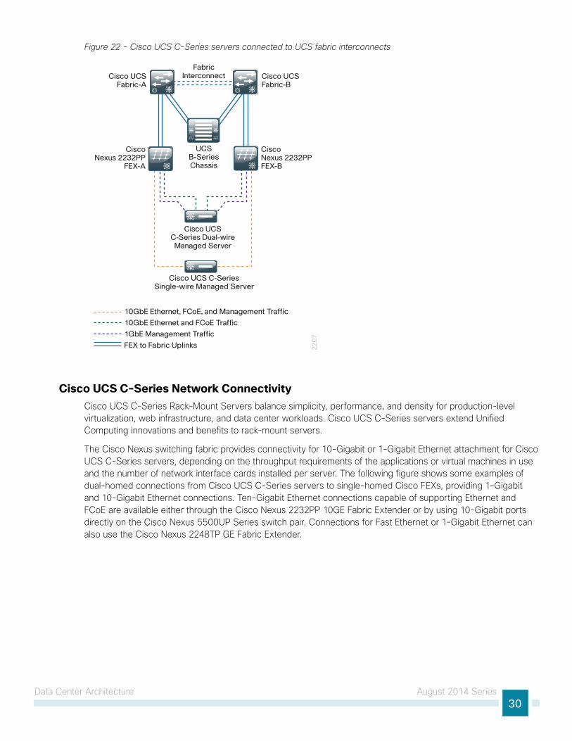
Figure 22 - Cisco UCS C-Series servers connected to UCS fabric interconnects
22
07
Cisco UCS Fabric-A
Cisco UCS Fabric-B
CiscoNexus 2232PP
FEX-A
CiscoNexus 2232PPFEX-B
FabricInterconnect
Cisco UCSC-Series Dual-wire Managed Server
UCSB-SeriesChassis
10GbE Ethernet, FCoE, and Management Traffic
10GbE Ethernet and FCoE Traffic
1GbE Management Traffic
FEX to Fabric Uplinks
Cisco UCS C-Series Single-wire Managed Server
Cisco UCS C-Series Network ConnectivityCisco UCS C-Series Rack-Mount Servers balance simplicity, performance, and density for production-level virtualization, web infrastructure, and data center workloads. Cisco UCS C-Series servers extend Unified Computing innovations and benefits to rack-mount servers.
The Cisco Nexus switching fabric provides connectivity for 10-Gigabit or 1-Gigabit Ethernet attachment for Cisco UCS C-Series servers, depending on the throughput requirements of the applications or virtual machines in use and the number of network interface cards installed per server. The following figure shows some examples of dual-homed connections from Cisco UCS C-Series servers to single-homed Cisco FEXs, providing 1-Gigabit and 10-Gigabit Ethernet connections. Ten-Gigabit Ethernet connections capable of supporting Ethernet and FCoE are available either through the Cisco Nexus 2232PP 10GE Fabric Extender or by using 10-Gigabit ports directly on the Cisco Nexus 5500UP Series switch pair. Connections for Fast Ethernet or 1-Gigabit Ethernet can also use the Cisco Nexus 2248TP GE Fabric Extender.

Data Center Architecture August 2014 Series31
Figure 23 - Example Cisco UCS C-Series FEX Connections
22
38
Cisco 2232PPFabric Extenders
Layer 2 vPC Links
Nexus 5500UPData Center Core
UCS C-Series Server 10 Gigabit
Ethernet and FCoE Connected
UCS C-Series Server
10 Gigabit Ethernet
UCS C-Series Server Multiple
1 GigabitEthernet
FEX Uplinks in
Port Channel Mode
Third-Party Computing SystemsThird-party rack server and blade server systems may also be connected to the data center topology with the available 10-Gigabit Ethernet interfaces on the Cisco Nexus 5500 Series switches, or interfaces on the Cisco Nexus 2000 Series Fabric Extenders that support Gigabit Ethernet and 10-Gigabit Ethernet connectivity, depending on the model selected. To support existing applications and facilitate smooth migration to servers that support the Cisco Unified Computing System features, you can easily integrate a previously installed base of running servers into the data center architecture.
Server Virtualization and Cisco UCSServer virtualization technologies allow a single physical server to run multiple virtual instances of a guest operating system, creating virtual machines. Running multiple virtual machines on server hardware helps to increase processor utilization levels, while still allowing each virtual machine to be viewed as independent from a security, configuration, and troubleshooting perspective.
Cisco Unified Computing System server platforms provide unique advantages that complement the implementation of server virtualization technologies. The Cisco UCS servers with Cisco UCS Manager allow the personality of a server instance to be easily ported to different physical hardware, similar to porting a virtual machine to a different host. Cisco UCS Manager provides the capability to directly integrate network interfaces to the hypervisor system for dynamic network interface allocation to virtual machines. This is currently supported with VMware ESX 4.0 Update 1 and above. Cisco Extended Memory Technology allows individual servers to scale to large numbers of virtual machines, reducing support and licensing costs.
Nexus 1000V and VMware DesignVirtualization allows you to run multiple workloads in one or more virtual machines (VMs) on a single physical server, with each VM consisting of an operating system and one or more applications. With virtualization, you can quickly move workloads from one physical server to another without any application downtime, enabling flexible and dynamic alignment of business needs with computing resources.
VMs are highly portable and can run unchanged on different physical servers because they consist only of a small number of files encapsulating applications, patches, data, and so forth. This structure allows separation of services from the underlying hardware.

Data Center Architecture August 2014 Series32
VMware Scalable SolutionsVMware ESXi is the next-generation, operating system–independent hypervisor that makes virtualization easy to deploy. Also known as the vSphere Hypervisor, it enables organizations to partition a physical server into multiple VMs to quickly start experiencing the benefits of virtualization. Requiring minimal configuration, users can be up and running in minutes with a production-ready hypervisor that scales to run the most resource-intensive applications.
VMware vSphere EditionsVMware vSphere is available for organizations in three main offerings targeted for various deployment scenarios. Each edition is licensed based on the number of processors on the physical server hosts that you want to virtualize. Each of the three editions scales easily when you add more licenses to your environment:
• VMware vSphere Standard provides an entry solution for basic consolidation of applications in order to slash hardware costs while accelerating application deployment.
• VMware vSphere Enterprise provides a strategic platform for minimizing downtime, protecting applications and data, and automating resource management.
• VMware vSphere Enterprise Plus includes the full range of components and features for transforming data centers into dramatically simplified cloud-computing environments that can provide the next generation of flexible, reliable IT services to their businesses.
Management ServersVMware vCenter Server is the simplest, most efficient way to manage VMware vSphere with scalability from a few to tens of thousands of VMs. From a single console, vCenter provides unified management of all the hosts and VMs in your data center. vCenter is available in several offerings targeted for various deployment scenarios. Each option includes vCenter, the central management tool for configuring, provisioning, and managing distributed virtual IT environments:
• VMware vCenter Server Standard provides large-scale management of VMware vSphere deployments for rapid provisioning, monitoring, orchestration, and control of virtual machines.
• VMware vCenter Foundation is the central management tool for up to three physical servers and is suitable for smaller environments looking to rapidly provision, monitor, and control virtual machines.
• VMware vSphere Essentials provides the same features as vCenter Foundation and is integrated with the Essentials and Essentials Plus starter kits.
VMware Enhanced Data Center AvailabilityVMware offers a wide range of products and solutions offering virtualization and resilience. VMware high availability provides rapid and automated restart and failover of VMs without the cost or complexity of solutions used with physical infrastructure. For server failures, VMware high availability automatically and intelligently restarts affected VMs on other production servers.
VMware Fault Tolerance provides true continuous availability for infrastructure and applications to further enhance service continuity. It enables critical applications to run with zero downtime and prevents data loss in spite of hardware failures.
VMware vMotion reduces planned downtime from server maintenance activities by enabling the live migration of running VMs from one server to another with no disruption or downtime.
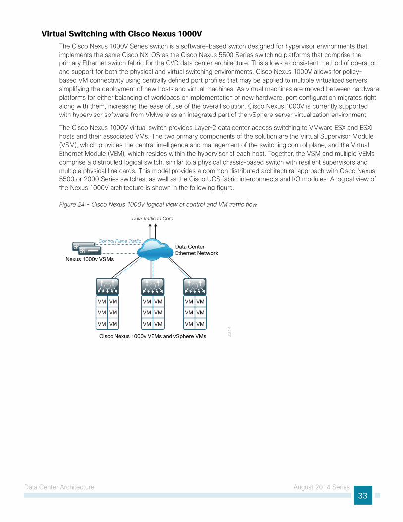
Data Center Architecture August 2014 Series33
Virtual Switching with Cisco Nexus 1000VThe Cisco Nexus 1000V Series switch is a software-based switch designed for hypervisor environments that implements the same Cisco NX-OS as the Cisco Nexus 5500 Series switching platforms that comprise the primary Ethernet switch fabric for the CVD data center architecture. This allows a consistent method of operation and support for both the physical and virtual switching environments. Cisco Nexus 1000V allows for policy-based VM connectivity using centrally defined port profiles that may be applied to multiple virtualized servers, simplifying the deployment of new hosts and virtual machines. As virtual machines are moved between hardware platforms for either balancing of workloads or implementation of new hardware, port configuration migrates right along with them, increasing the ease of use of the overall solution. Cisco Nexus 1000V is currently supported with hypervisor software from VMware as an integrated part of the vSphere server virtualization environment.
The Cisco Nexus 1000V virtual switch provides Layer-2 data center access switching to VMware ESX and ESXi hosts and their associated VMs. The two primary components of the solution are the Virtual Supervisor Module (VSM), which provides the central intelligence and management of the switching control plane, and the Virtual Ethernet Module (VEM), which resides within the hypervisor of each host. Together, the VSM and multiple VEMs comprise a distributed logical switch, similar to a physical chassis–based switch with resilient supervisors and multiple physical line cards. This model provides a common distributed architectural approach with Cisco Nexus 5500 or 2000 Series switches, as well as the Cisco UCS fabric interconnects and I/O modules. A logical view of the Nexus 1000V architecture is shown in the following figure.
Figure 24 - Cisco Nexus 1000V logical view of control and VM traffic flow
22
14
Nexus 1000v VSMs
Data CenterEthernet Network
Cisco Nexus 1000v VEMs and vSphere VMs
Data Traffic to Core
Control Plane Traffic
VM VM
VM VM
VM VM
VM VM
VM VM
VM VM
VM VM
VM VM
VM VM

Data Center Architecture August 2014 Series34
Cisco Nexus 1000V VEMThe Cisco Nexus 1000V VEM executes as part of the VMware ESX or ESXi kernel and provides a richer alternative feature set to the basic VMware virtual switch functionality. The VEM leverages the VMware vSphere distributed switch API, which was developed jointly by Cisco and VMware, to provide advanced networking capability to virtual machines. This level of integration ensures that the Cisco Nexus 1000V switch is fully aware of all server virtualization events, such as VMware vMotion and distributed resource scheduler. The VEM takes configuration information from the VSM and performs Layer 2 switching and advanced networking functions:
• Port channels
• QoS
• Security features, such as private VLAN, access control lists, port security, and DHCP snooping. To make context-aware access control decisions, Cisco TrustSec in Cisco Nexus 1000V combines with the Cisco Identity Services Engine.
• Monitoring functions, such as NetFlow, Switch Port Analyzer (SPAN), and Encapsulated Remote SPAN.
In the event of loss of communication with the VSM, the VEM has nonstop forwarding capability to continue to switch traffic based on the last-known configuration. In short, Cisco Nexus1000V brings data center switching and its operational model into the hypervisor to provide a consistent network management model from the core to the virtual machine NIC.
Cisco Nexus 1000V provides centralized configuration of switching capabilities for VEMs that support multiple hosts and VMs, allowing you to enable features or profiles in one place instead of reconfiguring multiple switches.
Nexus 1000V VSMThe Cisco Nexus 1000V Series VSM controls multiple VEMs as one logical modular switch. Instead of physical line-card modules, the VSM supports multiple VEMs running in software inside of the physical servers. Configuration is performed through the VSM and is automatically propagated to the VEMs. Instead of configuring soft switches inside the hypervisor on a host-by-host basis, administrators can define configurations for immediate use on all VEMs being managed by the VSM from a single interface. The VSM may be run as a VM on an ESX or ESXi host or on the dedicated Cisco Nexus 1010 hardware platform.
By using the capabilities of Cisco NX-OS, Cisco Nexus 1000V Series provides these benefits:
• Flexibility and Scalability—Port profiles, a Cisco NX-OS feature, provides configuration of ports by category, enabling the solution to scale to a large number of ports. Common software can run all areas of the data center network, including the LAN and SAN.
• High Availability—Synchronized, highly available VSMs enable rapid, stateful failover and help ensure an always-available virtual machine network.
• Manageability—The Cisco Nexus 1000V Series can be accessed through the Cisco CLI, simple network management protocol (SNMP), XML API, Cisco Data Center Network Manager, and Cisco Prime LAN Management Solution.
The VSM is also tightly integrated with VMware vCenter Server so that the virtualization administrator can take advantage of the network configuration in Cisco Nexus 1000V.

Data Center Architecture August 2014 Series35
Nexus 1000V Port ProfilesTo complement the ease of creating and provisioning VMs, Cisco Nexus 1000V includes the port profile feature in order to address configuration consistency challenges, which provides lower operational costs and reduces risk. Port profiles enable you to define reusable network policies for different types or classes of VMs from the Cisco Nexus 1000V VSM and then apply the profiles to individual VM virtual NICs through VMware’s vCenter.
Virtualized Network Services with Cisco vPathIn addition to virtual machine switching, Cisco Nexus 1000V Series supports Cisco vPath in order to provide a single architecture supporting multiple Layer 4 through 7 network services. In the Cisco vPath architecture, virtual service nodes can provide a variety of network services, such as virtual firewall, load balancing, and WAN acceleration. Specifically, the Cisco vPath architecture provides:
• Intelligent traffic steering—Redirect traffic from the server requesting a network service to the virtual service node (VSN) and extend port profiles to include the network service profile.
• Flexible deployment—Each VSN can serve multiple physical servers, and the VSN can be hosted on a separate or dedicated server.
• Network service acceleration—With Network Service Decision Caching, Cisco Nexus 1000V Series remembers network service policy from prior traffic, reducing traffic steering, and the performance of virtual network services can be accelerated through enforcement in the hypervisor kernel.
Nexus 1000V and VMware SummaryApplications are the heartbeat of your business and provide rich business functionality; VMware virtualization is the heartbeat of an infrastructure that drives tangible benefits for both the business and the IT organization. With VMware as the platform underlying your application landscape, infrastructure and application teams are empowered to do their work more efficiently and with fewer administrative headaches throughout the hardware and software lifecycle, from development through production and maintenance.
You can enhance the manageability of the VMware networking environment by installing Cisco Nexus 1000V. For high-performance, virtual machine environments, you can increase throughput and reduce latency with Cisco VM-FEX, while retaining the resilience and manageability of your VMware environment.

Summary August 2014 Series36
SummaryCisco CVD Enterprise data centers are proven solutions that accommodate your organization’s IT needs, from a small server room to a data center for organizations with up to 300 server ports. This out-of-the-box, lab-validated approach is easy to use, affordable, scalable, and flexible. The CVD enterprise data center architecture provides the ability for growing organizations to migrate from server room deployments to a scalable data center design.
This data center architecture incorporates Ethernet and storage network, computing resources, security, application resiliency, and virtualization tested together as a solution. This solution-level approach to building out an architecture simplifies the system integration normally associated with multiple technologies, allowing you to select the modules that meet your organization’s requirements rather than worrying about matching components and interoperability. The CVD data center design guides provide step-by-step guidance for deploying the solutions.

Glossary August 2014 Series37
GlossaryACL access control list
ASA Cisco Adaptive Security Appliance
CIFS common Internet file system
CIMC Cisco Integrated Management Controller
Cisco ASA Cisco Adaptive Security Appliance
CLI command line interface
CoS class of service
CVD Cisco Validated Designs
DAS direct attached storage
DCBX Data Center Bridging Exchange
DHCP dynamic host configuration protocol
DSCP differentiated services code point
FC Fibre Channel
FCoE fibre channel over Ethernet
FEX Cisco Fabric Extender
GUI graphical user interface
HA high availability
HBA host bus adaptor
IDS intrusion detection system
IPMI Intelligent Platform Management Interface
IPS intrusion prevention system
iSCSI Internet Small Computer System Interface
MCEC multichassis EtherChannel
NAS network attached storage
NFS network file server
NIC network interface card
PoE power over Ethernet
QoS Quality of Service
RBAC role-based access control
SAN storage area network
SNMP simple network management protocol

Glossary August 2014 Series38
SPAN Switch Port Analyzer
SSH secure shell protocol
STP spanning tree protocol
VEM Virtual Ethernet Module
VM virtual machine
vPC virtual port channel
VSAN virtual storage area network
VSM Virtual Supervisor Module
VSN virtual service node
VSS Cisco Catalyst Virtual Switching System
Americas HeadquartersCisco Systems, Inc.San Jose, CA
Asia Pacific HeadquartersCisco Systems (USA) Pte. Ltd.Singapore
Europe HeadquartersCisco Systems International BV Amsterdam,The Netherlands
Cisco has more than 200 offices worldwide. Addresses, phone numbers, and fax numbers are listed on the Cisco Website at www.cisco.com/go/offices.
ALL DESIGNS, SPECIFICATIONS, STATEMENTS, INFORMATION, AND RECOMMENDATIONS (COLLECTIVELY, “DESIGNS”) IN THIS MANUAL ARE PRESENTED “AS IS,” WITH ALL FAULTS. CISCO AND ITS SUPPLIERS DISCLAIM ALL WARRANTIES, INCLUDING, WITHOUT LIMITATION, THE WARRANTY OF MERCHANTABILITY, FITNESS FOR A PARTICULAR PURPOSE AND NONINFRINGEMENT OR ARISING FROM A COURSE OF DEALING, USAGE, OR TRADE PRACTICE. IN NO EVENT SHALL CISCO OR ITS SUPPLIERS BE LIABLE FOR ANY INDIRECT, SPECIAL, CONSEQUENTIAL, OR INCIDENTAL DAMAGES, INCLUDING, WITHOUT LIMITATION, LOST PROFITS OR LOSS OR DAMAGE TO DATA ARISING OUT OF THE USE OR INABILITY TO USE THE DESIGNS, EVEN IF CISCO OR ITS SUPPLIERS HAVE BEEN ADVISED OF THE POSSIBILITY OF SUCH DAMAGES. THE DESIGNS ARE SUBJECT TO CHANGE WITHOUT NOTICE. USERS ARE SOLELY RESPONSIBLE FOR THEIR APPLICATION OF THE DESIGNS. THE DESIGNS DO NOT CONSTITUTE THE TECHNICAL OR OTHER PROFESSIONAL ADVICE OF CISCO, ITS SUPPLIERS OR PARTNERS. USERS SHOULD CONSULT THEIR OWN TECHNICAL ADVISORS BEFORE IMPLEMENTING THE DESIGNS. RESULTS MAY VARY DEPENDING ON FACTORS NOT TESTED BY CISCO.
Any Internet Protocol (IP) addresses used in this document are not intended to be actual addresses. Any examples, command display output, and figures included in the document are shown for illustrative purposes only. Any use of actual IP addresses in illustrative content is unintentional and coincidental.
© 2014 Cisco Systems, Inc. All rights reserved.
Cisco and the Cisco logo are trademarks or registered trademarks of Cisco and/or its affiliates in the U.S. and other countries. To view a list of Cisco trademarks, go to this URL: www.cisco.com/go/trademarks. Third-party trademarks mentioned are the property of their respective owners. The use of the word partner does not imply a partnership relationship between Cisco and any other company. (1110R)
Please use the feedback form to send comments and suggestions about this guide.
Feedback
B-0000525-1 09/14