Data Center Access Layer Design - cisco.com · 6-3 Cisco Data Center Infrastructure 2.5 Design...
40
CHAPTER 6-1 Cisco Data Center Infrastructure 2.5 Design Guide OL-11565-01 6 Data Center Access Layer Design This chapter provides details of Cisco tested access layer solutions in the enterprise data center. It includes the following topics: • Overview of Access Layer Design Options • Layer 2 Looped Access Layer Model • Layer 2 Loop-Free Access Layer Model • FlexLinks Access Model Overview of Access Layer Design Options Access layer switches are primarily deployed in Layer 2 mode in the data center. A Layer 2 access topology provides the following unique capabilities required in the data center: • VLAN extension—The Layer 2 access topology provides the flexibility to extend VLANs between switches that are connected to a common aggregation module. This makes provisioning of servers to a particular subnet/VLAN simple, and without the worry of physical placement of the server in a particular rack or row. • Layer 2 adjacency requirements—NIC teaming, high availability clusters, and database clusters are application examples that typically require NIC cards to be in the same broadcast domain (VLAN). The list of applications used in a clustered environment is growing, and Layer 2 adjacency is a common requirement. • Custom applications—Many developers write custom applications without considering the Layer 3 network environment, either because of lack of skills or available tools. This can create challenges in a Layer 3 IP access topology. These servers usually depend on Layer 2 adjacency with other servers and could require rewriting code when changing IP addresses.
Transcript of Data Center Access Layer Design - cisco.com · 6-3 Cisco Data Center Infrastructure 2.5 Design...

OL-11565-01
C H A P T E R6
Data Center Access Layer DesignThis chapter provides details of Cisco tested access layer solutions in the enterprise data center. It includes the following topics:
• Overview of Access Layer Design Options
• Layer 2 Looped Access Layer Model
• Layer 2 Loop-Free Access Layer Model
• FlexLinks Access Model
Overview of Access Layer Design OptionsAccess layer switches are primarily deployed in Layer 2 mode in the data center. A Layer 2 access topology provides the following unique capabilities required in the data center:
• VLAN extension—The Layer 2 access topology provides the flexibility to extend VLANs between switches that are connected to a common aggregation module. This makes provisioning of servers to a particular subnet/VLAN simple, and without the worry of physical placement of the server in a particular rack or row.
• Layer 2 adjacency requirements—NIC teaming, high availability clusters, and database clusters are application examples that typically require NIC cards to be in the same broadcast domain (VLAN). The list of applications used in a clustered environment is growing, and Layer 2 adjacency is a common requirement.
• Custom applications—Many developers write custom applications without considering the Layer 3 network environment, either because of lack of skills or available tools. This can create challenges in a Layer 3 IP access topology. These servers usually depend on Layer 2 adjacency with other servers and could require rewriting code when changing IP addresses.
6-1Cisco Data Center Infrastructure 2.5 Design Guide

Chapter 6 Data Center Access Layer Design Overview of Access Layer Design Options
• Service modules—A Layer 2 access permits services provided by service modules or appliances to be shared across the entire access layer. Examples of this are when using the FWSM, CSM, and SSLSM. The active-standby modes of operation used by service modules require Layer 2 adjacency with the servers that use them.
• Administrative reasons—Large enterprise customers commonly consist of multiple business units and departments, often with their own individual set of IT personnel, which might be the result of acquisitions or scaling of a business. IP address space is often divided and used by these business units with specific boundaries defined, or it might be completely overlapping. As data center consolidations occur, these business units/departments begin to share common floor and rack space. The ability to group these departments with Layer 2 VLANs across multiple access switches could be a critical requirement in these environments.
The table in Figure 6-1 outlines the available access layer design models and provides a comparison of various factors to consider with each. Each access layer design model is covered in more detail in the remainder of this chapter.
Note It might be more valuable to institute a point system in place of the plus-minus rating to determine which access layer model would be more appropriate for a particular design.
Figure 6-1 Comparison Chart of Access Layer Designs
The table in Figure 6-1 contains the following column headings:
• Uplinks in blocking or standby state—Some access layer designs can use both uplinks (active-active), while others have one link active and the other blocked on a per-VLAN basis by spanning tree, or completely unused in a backup mode only. A plus is given to those models that have both uplinks active.
-++/-+++
+-+++-
+++--+
-+++++
++
FlexLinks
+-+-
(1, 2)
LoopedTriangle
LoopedSquare
Loop-freeInverted U
Loop-freeU
SingleAttached
Server Black-Holing on
Uplink Failure
AccessSwitch
Density perAgg Module
1530
46
Uplinks onAgg Switch
in Blocking orStandby State
VLANExtensionSupported
Across Access
ServiceModule
Black-Holingon UplinkFailure (5)
MustConsider
Inter-SwitchLink Scaling
(3)
(4)
1. Use of Distributed EtherChannel Greatly Reduces Chances of Black Holing Condition 2. NIC Teaming Can Eliminate Black Holing Condition3. When Service Modules Are Used and Active Service Modules Are Aligned to Agg14. ACE Module Permits L2 Loopfree Access with per Context Switchover on Uplink failure5. Applies to when using CSM or FWSM in active/standby arrangement
6-2Cisco Data Center Infrastructure 2.5 Design Guide
OL-11565-01

Chapter 6 Data Center Access Layer Design Overview of Access Layer Design Options
• VLAN extension across the access layer—A plus is given to those access design models that permit a VLAN to be extended to all access switches that are connected to a common aggregation module.
• Service module black holing—An uplink failure on the access layer switch could break connectivity between the servers and the service modules being used.
• Single attached server black holing—If an access switch has a single uplink, it could be a large failure exposure point. Uplinks that use Distributed EtherChannel can reduce the chances of black holing. Server load balancing to a VIP that includes servers physically connected across multiple access switches is another technique that can be used, as well as server NIC teaming.
• Access switch density per aggregation module—When 10GE uplinks are used, port density at the aggregation layer can be a challenge. Some access layer designs permit a larger number of access layer switches per aggregation module than others.
• Inter-switch link bandwidth scaling—Some access layer designs send all traffic towards the primary root aggregation switch, while other designs send traffic towards both aggregation switches. When sending to both aggregation switches, 50 percent of the traffic typically passes over the inter-switch link to reach the active HSRP default gateway and active service module pair. The amount of bandwidth used for the inter-switch links becomes very important in these designs and can create scaling challenges.
Service Module Influence on DesignThis section contains recommendations for service module implementations for each of the access layer design models described. Because service modules can be implemented in many different ways or none at all, the focus is on a single service module design that is commonly implemented using the FWSM and CSM modules (see Figure 6-2).
Note The Application Control Engine (ACE) is a new module that introduces several enhancements with respect to load balancing and security services. A key difference between the CSM, FWSM release 2.x, and ACE is the ability to support active-active contexts across the aggregation module with per context failover. The ACE module is not released at the time of this writing, so it is not covered.
6-3Cisco Data Center Infrastructure 2.5 Design Guide
OL-11565-01

Chapter 6 Data Center Access Layer Design Overview of Access Layer Design Options
Figure 6-2 CSM One-arm and FWSM Transparent Mode Design
The CSM one-arm combined with the FWSM transparent mode is a common implementation in the enterprise data center and has particular advantages over other designs. The main advantages lie in the areas of performance and virtualization.
Regarding performance, the CSM in one-arm mode allows client-to-server traffic to use the load balancer as necessary to balance web layer server access while allowing server-to-server traffic to bypass the CSM and use the switching capacity on the MSFC. The one-arm design also permits the real client IP address to remain intact (no client NAT) so that server applications can use it for demographic or other purposes.
The FWSM can be virtualized when operating in transparent mode. This allows individual contexts of firewall instances to be created, configured, and managed independently of each other. This allows a single FWSM module to be used across different lines of business or operations as if multiple physical firewalls existed.
Service Module/Appliance and Path PreferencesTo achieve redundancy, service modules are deployed in pairs. One module in the pair acts as the primary/active service module while the other module acts as the secondary/standby. Although service module pairs can deployed in the same aggregation chassis, they are typically placed in separate chasses to achieve the highest level of redundancy. Service modules are required to be Layer 2 adjacent on their configured VLAN interfaces to permit session state and monitoring to occur. For example, in Figure 6-2, vlan 11 on the FWSM in aggregation 1 must be extended to vlan 11 on the FWSM in aggregation 2 via the 802.1Q trunk inter-switch link. This is also true for vlans 12,13,21,22, and 23. This also applies to the server vlan 44 used by the CSM module in Figure 6-2.
1530
47
Aggregation 1 L3 Links
Core 2
802.1Q Trunk
VLAN 23
VLAN 22
VLAN 21
STP Primary RootHSRP Active
Service Module Active
STP Secondary RootHSRP Standby
Service Module Standby
Core 1
Aggregation 2
CSM CSM
Policy Based Routing
FWSM FWSM
Context 1
Context 3
Context 2
44
222321
121311
222321
121311
44
MSFC MSFC
6-4Cisco Data Center Infrastructure 2.5 Design Guide
OL-11565-01

Chapter 6 Data Center Access Layer Design Overview of Access Layer Design Options
Because only one service module in one aggregation switch can be active at any one time, Cisco recommends aligning traffic flow towards the primary service module(s). The active default gateway and spanning tree root bridge are two components that influence path selection in a Layer 2 network. If primary service modules are located in the aggregation 1 switch, it is desirable to define the HSRP primary default gateway and spanning tree root bridge to also be on the aggregation 1 switch. This prevents session flow from hopping back and forth between aggregation switches, optimizing inter-switch link usage and providing a more deterministic environment.
Note It is possible to double up on service modules and create a design such that active service modules are in each aggregation switch. This permits load balancing of access layer VLANs across uplinks to each aggregation switch without the need for flows to cross the inter-switch link between them. The disadvantage of this type of design is that there are twice the number of devices, with a corresponding increase in management and complexity.
When service modules/appliances are not used, access layer VLANs can be distributed across uplinks without concern for traffic flow issues. This can be achieved by alternating the HSRP active default gateway and spanning tree root configurations for each VLAN between the aggregation 1 and aggregation 2 switch, or by using Gateway Load Balancing Protocol (GLBP) in place of HSRP.
Because most data center implementations use service modules or appliances, the remainder of this chapter focuses on access layer topologies using service modules.
General RecommendationsThe remainder of this chapter covers the details of the various access layer design models. Although each meets their own specific requirements, the following general recommendations apply to all:
• Spanning tree pathcost—Cisco recommends optimizing the spanning tree design by implementing the “spanning-tree pathcost method long” global feature. The pathcost method long option causes spanning tree to use a 32 bit-based value in determining port path costs compared to the default 16 bit, which improves the root path selection when various EtherChannel configurations exist.
• EtherChannel protocol—Cisco also recommends using Link Aggregation Control Protocol (LACP) as the link aggregation protocol for EtherChannel configurations. LACP considers the total available bandwidth of an EtherChannel path to STP in determining the path cost. This is advantageous in situations where only a portion of an EtherChannel link fails and the blocked alternate link can provide a higher bandwidth path.
• Failover tracking with service modules and HSRP—HSRP tracking of an interface can be used to control switchover of the primary default gateway between aggregation switches. Service modules can also track interface state and be configured to failover based on various up/down criteria. Unfortunately, the service modules and HSRP do not work together and have different mechanisms to determine failover, which can create situations where active and standby components are misaligned across the aggregation layer.
There are specific situations where tracking can be of benefit, but for the most part Cisco recommends not using the various failover tracking mechanisms and relying instead on using the inter-switch aggregation links to reach active default gateway and service module(s) during failure conditions. For this reason, it is important to consider failure scenarios when determining the proper inter-switch link bandwidth to be used.
6-5Cisco Data Center Infrastructure 2.5 Design Guide
OL-11565-01

Chapter 6 Data Center Access Layer Design Layer 2 Looped Access Layer Model
• Service module timers—The convergence characteristics of various failure scenarios are influenced by the service module(s) failover timer configurations. Test lab results show that average service module failover times with these values are under ~6 seconds. The recommended service module failover timer configurations are as follows:
– CSM
module ContentSwitchingModule 3ft group 1 vlan 102priority 20heartbeat-time 1failover 3preempt
– FWSM
Unit Poll frequency 500 milliseconds, holdtime 3 secondsInterface Poll frequency 3 seconds
• Using Distributed EtherChannel (DEC)—Cisco generally recommends that the inter-switch link between aggregation switches be implemented with a DEC connection to provide the highest level of resiliency. There are known caveats in certain Cisco IOS releases related to using DEC when service modules are present. For more details, refer to the Release Notes for this guide.
Layer 2 Looped Access Layer ModelThis section covers Layer 2 looped access topologies, and includes of the following topics:
• Layer 2 Looped Access Topologies
• Triangle Looped Topology
• Square Looped Topology
Layer 2 Looped Access TopologiesIn a Layer 2 looped access topology, a pair of access layer switches are connected to the aggregation layer using 802.1Q trunks. Looped access topologies consist of a triangle and square design, as shown in Figure 6-3.
6-6Cisco Data Center Infrastructure 2.5 Design Guide
OL-11565-01

Chapter 6 Data Center Access Layer Design Layer 2 Looped Access Layer Model
Figure 6-3 Triangle and Square Looped Access Topologies
In Figure 6-3, a VLAN is configured on each access switch on the corresponding 802.1Q uplink, and is also extended between aggregation switches, forming a looped topology for that VLAN. The left side of the diagram shows an access layer with a triangle looped topology, and the right side shows a square looped topology. In the triangle looped topology, the access switch is dual homed to each aggregation switch. In the square looped topology, a pair of access switches are interconnected together, with each connected to a single aggregation switch.
Because a loop is present, all links cannot be in a forwarding state at all times. Because broadcasts/multicast packets and unknown unicast MAC address packets must be flooded, they would travel in an endless loop, completely saturating the VLAN and adversely affecting network performance. A spanning tree protocol such as Rapid PVST+ or MST is required to automatically block a particular link and break this loop condition.
The dashed black lines on the aggregation layer switches represent the demarcation between Layer 2 and Layer 3 for the VLANs that are extended to the access layer switches. All packets processed in the VLAN beneath this line are in the same Layer 2 broadcast domain and are Layer 3 routed above the line. As denoted by the double solid lines, spanning tree automatically blocks one path to break the loop condition.
In both looped topologies, the service module fault-tolerant VLANs are extended between aggregation switches over the 802.1Q inter-switch link. This permits active-standby hellos and session state communications to take place to support redundancy.
1530
48
L3L2
L3L2
L2 Looped Triangle L2 Looped Square
10GE or 10GEC 802.1Q TrunksGE or EtherChannelBackup/NIC TeamingBlocked Path by Spanning Tree
Vlan 10 Vlan 20
6-7Cisco Data Center Infrastructure 2.5 Design Guide
OL-11565-01

Chapter 6 Data Center Access Layer Design Layer 2 Looped Access Layer Model
Triangle Looped TopologyThe triangle looped topology is currently the most widely implemented in the enterprise data center. This topology provides a deterministic design that makes it easy to troubleshoot while providing a high level of flexibility (see Figure 6-4).
Figure 6-4 Triangle Looped Access Topology
Spanning Tree, HSRP, and Service Module Design
In a triangle looped access layer design, it is desirable to align the spanning tree root, HSRP default gateway, and active service modules on the same aggregation switch, as shown in Figure 6-4. Aligning the access layer switch uplink that is in the forwarding state directly to the same switch that is the primary default gateway and active service module/appliance optimizes the traffic flows. Otherwise, traffic flows can hop back and forth between aggregation switches, creating undesirable conditions and difficulty in troubleshooting.
1530
49
L3L2
10GE or 10GEC 802.1Q TrunksGE or EtherChannelBackup/NIC TeamingBlocked Path by Spanning Tree
Vlan 10 Vlan 20
Root PrimaryHSRP Primary
Active Services
Root SecondaryHSRP SecondaryStandby Services
Row 2, Cabinet 3 Row 9, Cabinet 8
Vlan 10
6-8Cisco Data Center Infrastructure 2.5 Design Guide
OL-11565-01

Chapter 6 Data Center Access Layer Design Layer 2 Looped Access Layer Model
Failure Scenarios
The level of resiliency that is incorporated into the access layer design can vary based on the model used. Other features such as route health injection and route tuning can influence this. This section describes the four main failure scenarios that can occur in a looped access design. Understanding the amount of exposure a customer faces in these scenarios helps in selecting the best access layer design.
Failure 1—Access Layer Uplink Failure
In this failure scenario, spanning tree unblocks the uplink to aggregation 2 because no loop exists (see Figure 6-5).
Figure 6-5 Triangle Looped Failure Scenario 1—Uplink Down
Default gateway and active service modules remain on aggregation 1 unless tracking mechanisms are configured and triggered. Traffic flow goes through aggregation 2 and uses the inter-switch link to aggregation 1 to reach the active HSRP default gateway and active service module.
The convergence characteristics of this failure scenario depend on spanning tree. Test lab results show that with Rapid-PVST+ implementations, this value should be under ~1.5 seconds, but can vary based on the number of spanning tree logical and virtual ports per line card values used.
Failure 2—Service Module Failure (Using CSM One-arm and FWSM Transparent Mode)
In this failure scenario, there is no spanning tree convergence, and the primary default gateway remains active on the aggregation 1 switch (see Figure 6-6).
1530
50
L3L2
Vlan 10
Root PrimaryHSRP Primary
Active Services
Root SecondaryHSRP SecondaryStandby Services
1
6-9Cisco Data Center Infrastructure 2.5 Design Guide
OL-11565-01

Chapter 6 Data Center Access Layer Design Layer 2 Looped Access Layer Model
Figure 6-6 Triangle Looped Failure Scenario 2—Service Modules
The backup service module moves to the active state on aggregation 2 because it no longer receives hello packets from the active service module, and times out.
Figure 6-6 shows the two following failure instances:
• 2.1 (FWSM failure)—Traffic flow goes through aggregation 1 and across the inter-switch link to aggregation 2, through the now active FWSM module context, and back across the inter-switch link to the active HSRP default gateway on the aggregation 1 MSFC. Because the CSM is still active in aggregation 1, return traffic flow is directed to the CSM based on the PBR configuration on the MSFC VLAN interface, and on to the client via the core.
• 2.2 (CSM failure)—Traffic flow goes through aggregation 1, through the active FWSM module context in aggregation 1, and to the MSFC VLAN interface. The MSFC VLAN interface PBR configuration forces the return CSM traffic to travel across the inter-switch link to aggregation 2 and through the now active CSM module. Because the active default gateway of the CSM server VLAN is still active on aggregation 1, the traffic must flow back across the inter-switch link to the MSFC on aggregation 1 and then on to the client via the core.
1530
51
msfc vlan interface
L3L2
Vlan 10
Root PrimaryHSRP Primary
Active CSM
Root SecondaryHSRP Secondary
Active FWSM
Vlan 10
Root PrimaryHSRP PrimaryActive FWSM
Root SecondaryHSRP Secondary
Active CSM
22L3L2
21
6-10Cisco Data Center Infrastructure 2.5 Design Guide
OL-11565-01

Chapter 6 Data Center Access Layer Design Layer 2 Looped Access Layer Model
Failure 3—Inter-Switch Link Failure
Figure 6-7 shows failure scenario 3.
Figure 6-7 Triangle Looped Failure Scenario 3—Inter-Switch Link Failure
This failure scenario has many side effects to consider. First, spanning tree unblocks the uplink to aggregation 2 because no loop exists. RootGuard on the aggregation switch then automatically disables the link to access 2 because it sees root BPDUs on the now-unblocked path to Aggregation 1 via the access layer switch.
With the inter-switch link down and RootGuard disabling the path to Aggregation 1 via access2, HSRP multicast hello messages no longer have a path between Aggregation 1 and 2, so HSRP goes into an active state on both switches for all VLANs.
Because the service module failover VLANs are configured across the inter-switch link only, service modules in both aggregation switches determine that the other has failed and become active (this is referred to as a split-brain effect).
If inbound traffic from the core flows into the aggregation 2 switch during this failure scenario, it attempts to flow through the now-active service modules and stop, because RootGuard has the path to the servers blocked. If for some reason RootGuard is not configured, this still results in asymmetrical flows and breaks connectivity. It is for these reasons that Cisco recommends tuning the aggregation-core routing configuration such that the aggregation 1 switch is the primary route advertised to the core for the primary service module-related VLANs.
Route tuning plus RootGuard prevents asymmetrical connections and black holing in a split-brain scenario because traffic flows are aligned with the same default gateway and service module combination, preventing asymmetrical conditions. More detail on route tuning can be found in Establishing Path Preference with RHI, page 7-1.
1530
52
L3L2
Vlan 10
Root PrimaryHSRP Active
Active Services
Root SecondaryHSRP Active
Active Services
3
RootGuardBlocks Path
6-11Cisco Data Center Infrastructure 2.5 Design Guide
OL-11565-01

Chapter 6 Data Center Access Layer Design Layer 2 Looped Access Layer Model
Failure 4—Switch Power or Sup720 Failure (Non-redundant)
Figure 6-8 shows failure scenario 4.
Figure 6-8 Triangle Looped Failure Scenario 4—Single Sup720 or Power Failure
In this failure scenario, the spanning tree root, primary default gateway, and active service modules transition to the aggregation 2 switch.
The convergence characteristics of this failure scenario depend on spanning tree, HSRP, and service module failover times. Because the spanning tree and HSRP failover times are expected to be under that of service modules, the actual convergence time depends on service module timer configurations.
Square Looped TopologyThe square-based looped topology is not as common today in the enterprise data center but has recently gained more interest. The square looped topology increases the access layer switch density when compared to a triangle loop topology while retaining the same loop topology characteristics. This becomes particularly important when 10GE uplinks are used. This topology is very similar to the triangle loop topology, with differences in where spanning tree blocking occurs (see Figure 6-9).
1530
53
L3L2
Vlan 10
Root SecondaryHSRP Active
Active Services
4
6-12Cisco Data Center Infrastructure 2.5 Design Guide
OL-11565-01

Chapter 6 Data Center Access Layer Design Layer 2 Looped Access Layer Model
Figure 6-9 Square Looped Access Topology
Spanning tree blocks the link between the access layer switches, with the lowest cost path to root being via the uplinks to the aggregation switches, as shown in Figure 6-9. This allows both uplinks to be active to the aggregation layer switches while providing a backup path in the event of an uplink failure. The backup path can also be a lower bandwidth path because it is used only in a backup situation. This might also permit configurations such as 10GE uplinks with GEC backup.
The possible disadvantages of the square loop design relate to inter-switch link use, because 50 percent of access layer traffic might cross the inter-switch link to reach the default gateway/active service module. There can also be degradation in performance in the event of an uplink failure because, in this case, the oversubscription ratio doubles.
Figure 6-9 shows the spanning tree blocking point on the link between the access switch pair. This is ideal if active services are deployed in each aggregation switch because it permits the uplinks to be load balanced without traversing the aggregation layer inter-switch trunk. If active services are only on Agg1, it might be desirable to adjust the STP cost such that the uplink to Agg2 is blocking instead of the link between the access pair. This forces all traffic to the Agg1 switch without having to traverse the aggregation layer inter-switch trunk.
1530
54
L3L2
10GE or 10GEC 802.1Q TrunksGE or EtherChannelBackup/NIC TeamingBlocked Path by Spanning Tree
Vlan 10 Vlan 20
Root PrimaryHSRP PrimaryActive Services
Root SecondaryHSRP SecondaryStandby Services
Row 2, Cabinet 3 Row 9, Cabinet 8
Vlan 10
6-13Cisco Data Center Infrastructure 2.5 Design Guide
OL-11565-01
Chapter 6 Data Center Access Layer Design Layer 2 Looped Access Layer Model
Spanning Tree, HSRP, and Service Module Design
Similar to a triangle design, it is desirable in a square looped access layer design to align the spanning tree root, HSRP default gateway, and active service modules on the same aggregation switch, as shown in Figure 6-9. By aligning the access layer switch uplink that is in the forwarding state directly to the same switch that is the primary default gateway and active service module/appliance, traffic flows are optimized. Otherwise, traffic flows can hop back and forth between aggregation switches, creating undesirable conditions that are unpredictable and difficult to troubleshoot.
Failure Scenarios
This section examines the square loop design in various failure scenarios.
Failure 1—Access Layer Uplink Failure
Figure 6-10 shows failure scenario 1.
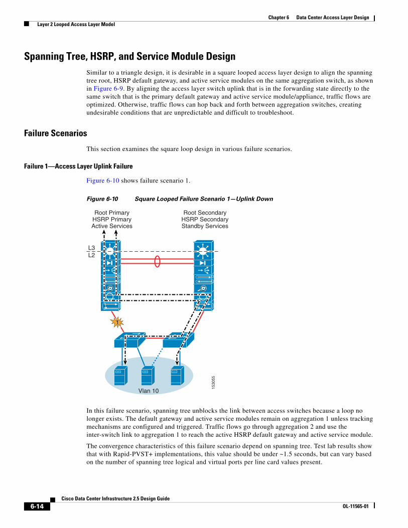
Figure 6-10 Square Looped Failure Scenario 1—Uplink Down
In this failure scenario, spanning tree unblocks the link between access switches because a loop no longer exists. The default gateway and active service modules remain on aggregation 1 unless tracking mechanisms are configured and triggered. Traffic flows go through aggregation 2 and use the inter-switch link to aggregation 1 to reach the active HSRP default gateway and active service module.
The convergence characteristics of this failure scenario depend on spanning tree. Test lab results show that with Rapid-PVST+ implementations, this value should be under ~1.5 seconds, but can vary based on the number of spanning tree logical and virtual ports per line card values present.
1530
55
L3L2
Vlan 10
Root PrimaryHSRP PrimaryActive Services
Root SecondaryHSRP SecondaryStandby Services
1
6-14Cisco Data Center Infrastructure 2.5 Design Guide
OL-11565-01

Chapter 6 Data Center Access Layer Design Layer 2 Looped Access Layer Model
Failure 2—Service Module Failure (using CSM One-arm and FWSM Transparent Mode)
In the failure scenario shown in Figure 6-11, there is no spanning tree convergence, and the primary default gateway remains active on the aggregation 1 switch.
Figure 6-11 Square Looped Failure Scenario 2—Service Modules
The backup service module moves to the active state on aggregation 2 because it no longer receives hello packets from the active service module, and times out.
The following failure scenarios are shown:
• 2.1 (FWSM failure)—Traffic flow goes through aggregation 1 and across the inter-switch link to aggregation 2, through the now-active FWSM module context, and back across the inter-switch link to the active HSRP default gateway on the aggregation 1 MSFC. Because the CSM is still active in aggregation 1, return traffic flow is directed to the CSM based on the PBR configuration on the MSFC VLAN interface, and then on to the client via the core.
• 2.2 (CSM failure)—Traffic flow goes through aggregation 1, through the active FWSM module context in aggregation 1, and to the MSFC VLAN interface. The MSFC VLAN interface PBR configuration forces return CSM traffic to travel across the inter-switch link to aggregation 2 and through the now-active CSM module. Because the active default gateway of the CSM server VLAN is still active on aggregation 1, the traffic must flow back across the inter-switch link to the MSFC on aggregation 1, and then on to the client via the core.
1530
56
msfc vlan interface
L3L2
Vlan 10
Root PrimaryHSRP Primary
Active CSM
Root SecondaryHSRP Secondary
Active FWSM
21
Vlan 10
Root PrimaryHSRP PrimaryActive FWSM
Root SecondaryHSRP Secondary
Active CSM
22L3L2
6-15Cisco Data Center Infrastructure 2.5 Design Guide
OL-11565-01

Chapter 6 Data Center Access Layer Design Layer 2 Looped Access Layer Model
Failure 3—Inter-Switch Link Failure
Figure 6-12 shows failure scenario 3.
Figure 6-12 Square Looped Failure Scenario 3—Inter-Switch Link Failure
This failure scenario has many side effects to consider. First, spanning tree unblocks the access layer inter-switch link because a loop no longer exists. RootGuard on the aggregation switch then automatically disables the link to access 2 because it sees root BPDUs via the now-unblocked path to aggregation 1.
With the inter-switch link down and RootGuard disabling the path to aggregation 1 via access 2, HSRP multicast hello messages no longer have a path between aggregation 1 and 2, so HSRP goes into an active state on both switches for all VLANs.
Because the service module failover VLANs are configured across the inter-switch link only, service modules in both aggregation switches determine that the other has failed. This results in service modules in aggregation 1 remaining in the active state, and service modules in aggregation 2 moving from standby to the active state as well. This is commonly referred to as a split-brain effect and is very undesirable.
If inbound traffic from the core flows into the aggregation 2 switch during this failure scenario, it attempts to flow through the now-active service modules and stops, because RootGuard has the path to the servers blocked. If for some reason RootGuard is not configured, this still results in asymmetrical flows and breaks connectivity. For these reasons, Cisco recommends tuning the aggregation-core routing configuration such that the aggregation 1 switch is the primary route advertised to the core for the primary service module-related VLANs.
Route tuning plus RootGuard prevents asymmetrical connections and black holing in a split-brain scenario because traffic flows are aligned with the same default gateway and service module combination, preventing asymmetrical conditions.
1530
57
L3L2
Vlan 10
Root PrimaryHSRP Active
Active Services
Root SecondaryHSRP Active
Active Services
3
RootGuardBlocks Path
6-16Cisco Data Center Infrastructure 2.5 Design Guide
OL-11565-01
Chapter 6 Data Center Access Layer Design Layer 2 Loop-Free Access Layer Model
Failure 4—Switch Power or Sup720 Failure (Non-redundant)
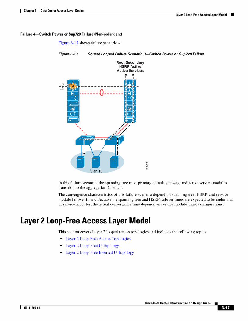
Figure 6-13 shows failure scenario 4.
Figure 6-13 Square Looped Failure Scenario 3—Switch Power or Sup720 Failure
In this failure scenario, the spanning tree root, primary default gateway, and active service modules transition to the aggregation 2 switch.
The convergence characteristics of this failure scenario depend on spanning tree, HSRP, and service module failover times. Because the spanning tree and HSRP failover times are expected to be under that of service modules, the actual convergence time depends on service module timer configurations.
Layer 2 Loop-Free Access Layer ModelThis section covers Layer 2 looped access topologies and includes the following topics:
• Layer 2 Loop-Free Access Topologies
• Layer 2 Loop-Free U Topology
• Layer 2 Loop-Free Inverted U Topology
1530
58
L3L2
Vlan 10
Root SecondaryHSRP Active
Active Services
4
6-17Cisco Data Center Infrastructure 2.5 Design Guide
OL-11565-01
Chapter 6 Data Center Access Layer Design Layer 2 Loop-Free Access Layer Model
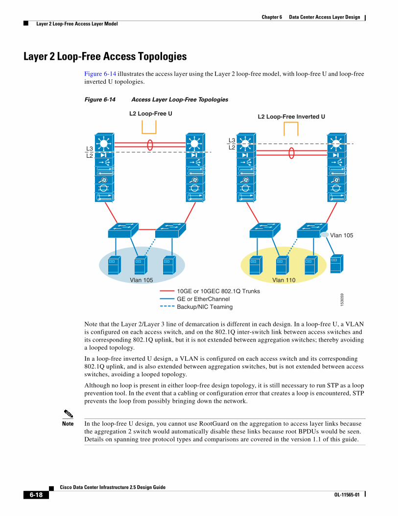
Layer 2 Loop-Free Access TopologiesFigure 6-14 illustrates the access layer using the Layer 2 loop-free model, with loop-free U and loop-free inverted U topologies.
Figure 6-14 Access Layer Loop-Free Topologies
Note that the Layer 2/Layer 3 line of demarcation is different in each design. In a loop-free U, a VLAN is configured on each access switch, and on the 802.1Q inter-switch link between access switches and its corresponding 802.1Q uplink, but it is not extended between aggregation switches; thereby avoiding a looped topology.
In a loop-free inverted U design, a VLAN is configured on each access switch and its corresponding 802.1Q uplink, and is also extended between aggregation switches, but is not extended between access switches, avoiding a looped topology.
Although no loop is present in either loop-free design topology, it is still necessary to run STP as a loop prevention tool. In the event that a cabling or configuration error that creates a loop is encountered, STP prevents the loop from possibly bringing down the network.
Note In the loop-free U design, you cannot use RootGuard on the aggregation to access layer links because the aggregation 2 switch would automatically disable these links because root BPDUs would be seen. Details on spanning tree protocol types and comparisons are covered in the version 1.1 of this guide.
1530
59
Vlan 105
L3L2
L3L2
L2 Loop-Free U L2 Loop-Free Inverted U
10GE or 10GEC 802.1Q TrunksGE or EtherChannelBackup/NIC Teaming
Vlan 105 Vlan 110
6-18Cisco Data Center Infrastructure 2.5 Design Guide
OL-11565-01

Chapter 6 Data Center Access Layer Design Layer 2 Loop-Free Access Layer Model
In both loop-free topologies, the service module fault-tolerant VLANs are extended between aggregation switches over the 802.1Q inter-switch link. This permits active-standby hellos and session state communications to take place to support redundancy.
Layer 2 Loop-Free U TopologyThe loop-free U topology design provides a Layer 2 access solution with active uplinks and redundancy via an inter-switch link between the access layer switches. The chance of a loop condition is reduced but spanning tree is still configured in the event of cabling or configuration errors occur (see Figure 6-15).
Figure 6-15 Loop-Free U Access Topology
With a loop-free U topology, there are no blocked paths by spanning tree because a loop does not exist. The VLANs are configured on the access layer uplink 802.1Q trunks and access layer inter-switch 802.1Q trunks but are not extended between the aggregation layer switches (note the dashed line designating the Layer 2 and Layer 3 boundaries). The service module fault tolerant VLANs are carried across the 802.1Q trunk for redundancy operations.
This topology allows both uplinks to be active for all VLANs to the aggregation layer switches while providing a backup path in the event of an uplink failure. This also permits a higher density of access switches to be supported on the aggregation module.
1530
60
Root PrimaryHSRP PrimaryActive Services
Root SecondaryHSRP SecondaryStandby Services
FT Vlanscarried acrossinter-switch link
L3L2
10GE or 10GEC 802.1Q TrunksGE or EtherChannelBackup/NIC Teaming
Vlan 105 Vlan 110
msfc vlan interface
6-19Cisco Data Center Infrastructure 2.5 Design Guide
OL-11565-01

Chapter 6 Data Center Access Layer Design Layer 2 Loop-Free Access Layer Model
The main disadvantages of the loop-free U design is the inability to extend VLANs outside of an access pair, and failure conditions that can create black holes in the event of an uplink failure when service modules are used. Extending VLANs outside of a single access pair creates a loop through the aggregation layer, essentially creating a four-node looped topology with blocked links. The black holes condition is covered in the failure scenarios later in this section.
Spanning Tree, HSRP, and Service Module Design
Because a loop does not exist in the topology, it does not actually require a spanning tree protocol to be running. However, it is very wise to maintain spanning tree in case an error creates a loop condition. It is also still recommended to maintain spanning tree primary root and secondary root configurations just as in the triangle and square looped topology designs. This way, if a loop error condition does exist, the service module and default gateway still operate optimally.
Note Cisco does not recommend using the loop-free U design in the presence of service modules because of black holing in the event of an uplink failure. More detail is covered in the failure scenarios part of this section. Service modules can be used with a loop-free inverted U topology when the design permits server black holing conditions and uses other mechanisms, such as when load balancers are combined with server distribution across the access layer.
Failure Scenarios
This section describes the loop-free U design in various failure scenarios.
6-20Cisco Data Center Infrastructure 2.5 Design Guide
OL-11565-01

Chapter 6 Data Center Access Layer Design Layer 2 Loop-Free Access Layer Model
Failure 1—Access Layer Uplink Failure
Figure 6-16 shows failure scenario 1.
Figure 6-16 Loop-Free U Failure Scenario 1—Uplink Failure
In this failure scenario, HSRP multicast hellos are no longer exchanged between the aggregation switches, which creates an active-active HSRP state for the vlan 5 and 10 MSFC interfaces on both aggregation switches.
The servers on access pair 1 are not able to reach the active FWSM context on aggregation 1 because there is no Layer 2 path for vlan 105 across the aggregation layer inter-switch links. Although the FWSM can be configured to switchover the active-standby roles by using the interface monitoring features, this requires the entire module to switchover (all contexts) on a single uplink failure. This is not a desirable condition and is further complicated if there are multiple uplink failures, or when maintenance requires taking down an access layer switch/uplink.
Note Because of the lack of single context failover, improved tracking and mis-aligned components, Cisco does not recommend using service modules with the loop-free U topology.
1530
62
1
Vlan 44
Vlan 5, 10 outside
Vlan 105, 110 inside
L3L2
Vlan 105 Vlan 110
HSRP ActiveActive Services
HSRP ActiveStandby Services
FT Vlanscarried acrossinter-switch link
Vlan 44
Vlan 5, 10 outside
Vlan 105, 110 inside
Access Pair 1 Access Pair 2
msfc vlan interface
6-21Cisco Data Center Infrastructure 2.5 Design Guide
OL-11565-01

Chapter 6 Data Center Access Layer Design Layer 2 Loop-Free Access Layer Model
Failure 2—Inter-Switch Link Failure
Figure 6-17 shows failure scenario 2.
Figure 6-17 Loop-Free U Failure Scenario 2—Inter-Switch Link Failure
This failure scenario has many side effects to consider. Because the service module failover VLANs are configured across the inter-switch link only, service modules in both aggregation switches determine that the other has failed. This results in service modules in aggregation 1 remaining in the active state, and service modules in aggregation 2 moving from standby to the active state as well. This is commonly referred to as a split-brain effect, and is very undesirable because the opportunity for asymmetrical connection failure exists.
The HSRP heartbeats travel along the access layer path, so HSRP remains in the same state with primary on aggregation 1 and standby on aggregation 2.
If inbound traffic from the core flows into the aggregation 2 switch during this failure scenario, it reaches the MSFC and then attempts to flow through the now-active service modules. By default, the core switches are performing CEF-based load balancing, thereby distributing sessions to both aggregation 1 and 2. Because state is maintained on the service modules, it is possible that asymmetrical connection failures can occur. For these reasons, Cisco recommends tuning the aggregation-core routing configuration such that the aggregation 1 switch is the primary route from the core for the primary service module-related VLANs.
Route tuning prevents asymmetrical connections and black holing in a split-brain scenario because traffic flows are aligned with the same default gateway and service module combination, preventing asymmetrical conditions. More information on route tuning can be found in Establishing Path Preference with RHI, page 7-1.
1530
63
msfc vlan interface
L3L2
Vlan 10
HSRP PrimaryActive CSM
Active FWSM
HSRP SecondaryActive CSM
Active FWSM
2
FT Vlans carried on aggregation layerinter-switch links
6-22Cisco Data Center Infrastructure 2.5 Design Guide
OL-11565-01

Chapter 6 Data Center Access Layer Design Layer 2 Loop-Free Access Layer Model
Failure 3—Switch Power or Sup720 Failure (Non-redundant)
Figure 6-18 shows failure scenario 3.
Figure 6-18 Loop-Free U Failure Scenario 3—Single Sup720 or Power Failure
In this failure scenario, the spanning tree root, primary default gateway, and active service modules transition to the aggregation 2 switch.
The convergence characteristics of this failure scenario depend on spanning tree, HSRP, and service module failover times. Because the spanning tree and HSRP failover times are expected to be under that of service modules, the actual convergence time depends on service module timer configurations. Test lab results show this convergence time to be ~ 6 seconds.
Layer 2 Loop-Free Inverted U TopologyThe loop-free inverted-U topology design provides a Layer 2 access solution with a single active access layer uplink to a single aggregation switch, as shown in Figure 6-19.
1530
64
msfc vlan interface
Vlan 10
HSRP PrimaryActive FWSM
HSRP SecondaryActive CSM
3
L3L2
FT Vlans carried on aggregation layerinter-switch links
6-23Cisco Data Center Infrastructure 2.5 Design Guide
OL-11565-01

Chapter 6 Data Center Access Layer Design Layer 2 Loop-Free Access Layer Model
Figure 6-19 Loop-Free Inverted-U Access Topology
With a loop-free inverted-U topology, there are no blocked paths by spanning tree because a loop does not exist. The VLANs are configured on the access layer uplink 802.1Q trunks and are extended between the aggregation layer switches (note the dashed line designating the Layer 2 and Layer 3 boundaries). The service module fault tolerant VLANs are carried across the aggregation inter-switch 802.1Q trunk for redundancy operations. This topology allows both uplinks to be active for all VLANs to the aggregation layer switches and permits VLAN extension across the access layer. The loop-free inverted-U design does not provide a backup link at the access layer, but resiliency can be improved by the use of distributed EtherChannel (DEC), as shown in Figure 6-19.
The main disadvantage of the loop-free inverted-U design can be attributed to an aggregation switch failure or access switch uplink failure that black holes servers because there is no alternate path available. The following improvements to the design can offset the effects of these failures and improve overall resiliency:
• Aggregation nodes with redundant Sup720s using NSF/SSO
• Distributed EtherChannel uplinks
• NIC teaming
• Server load balancing with REALS spread across access switches
1530
65
L3L2
10GE or 10GEC 802.1Q TrunksGE or EtherChannelBackup/NIC Teaming
Vlan 105 Vlan 110
Root PrimaryHSRP Primary
Active Services
Root SecondaryHSRP SecondaryStandby Services
Vlan 105
msfc vlan interface
6-24Cisco Data Center Infrastructure 2.5 Design Guide
OL-11565-01

Chapter 6 Data Center Access Layer Design Layer 2 Loop-Free Access Layer Model
Spanning Tree, HSRP, and Service Module Design
Because a loop does not exist in the topology, it does not require a spanning tree protocol to be running. However, Cisco recommends maintaining spanning tree in case an error creates a loop condition. Cisco also still recommends maintaining spanning tree primary root and secondary root configurations just as in the triangle and square looped topology designs. This way if a loop error condition does exist, the service module and default gateway still operate optimally.
As in all other access layer designs that use service modules, Cisco recommends aligning the HSRP default gateway, STP root, and active service modules on the same aggregation switch. If the primary default gateway and active service modules are not aligned, it creates session flows that travel across the inter-switch links unnecessarily.
When HSRP, STP root, and primary service modules are aligned, the session flows are more optimal, easier to troubleshoot, and deterministic, as shown in Figure 6-20. Note that in a loop-free inverted-U topology, 50 percent of the session flows use the aggregation layer inter-switch link to reach the active HSRP default gateway and active service modules.
Figure 6-20 Loop-Free Inverted-U with HSRP and Service Modules Aligned –Recommended
1530
67
L3L2
Vlan 105 Vlan 110
HSRP SecondaryStandby Services
HSRP PrimaryActive Services
msfc vlan interface
6-25Cisco Data Center Infrastructure 2.5 Design Guide
OL-11565-01
Chapter 6 Data Center Access Layer Design Layer 2 Loop-Free Access Layer Model
Failure Scenarios
This section describes the loop-free inverted-U design in various failure scenarios.
Failure 1—Access Layer Uplink Failure
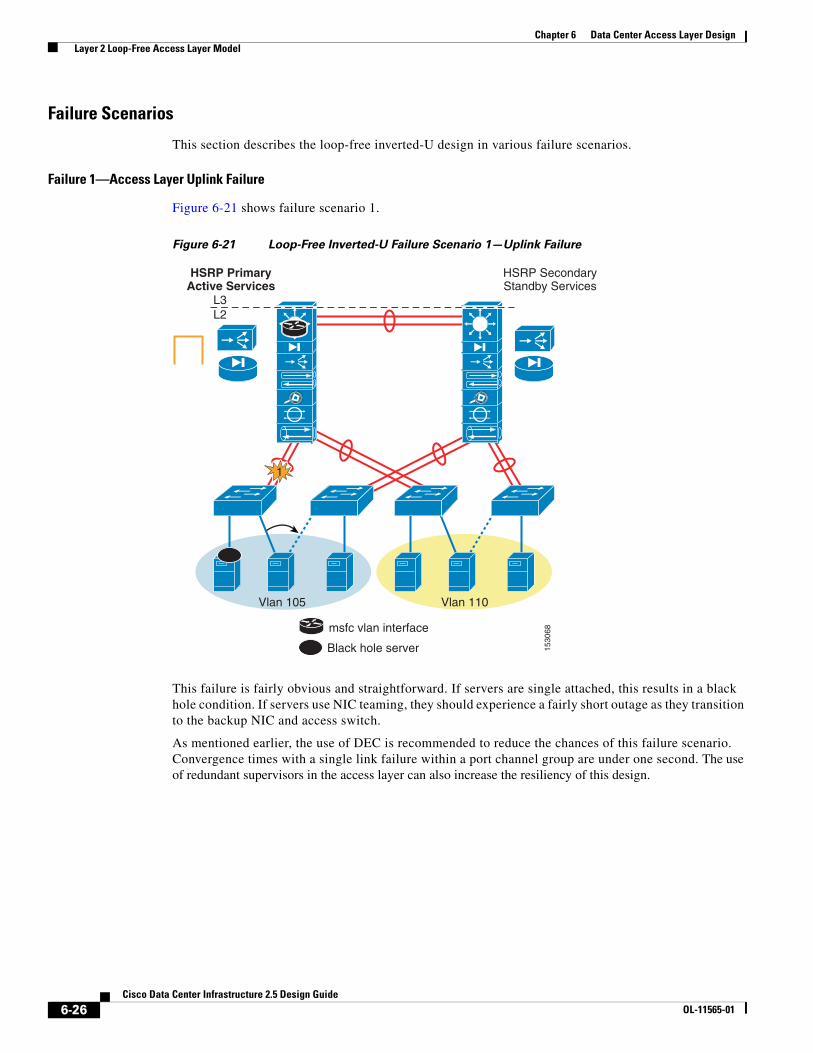
Figure 6-21 shows failure scenario 1.
Figure 6-21 Loop-Free Inverted-U Failure Scenario 1—Uplink Failure
This failure is fairly obvious and straightforward. If servers are single attached, this results in a black hole condition. If servers use NIC teaming, they should experience a fairly short outage as they transition to the backup NIC and access switch.
As mentioned earlier, the use of DEC is recommended to reduce the chances of this failure scenario. Convergence times with a single link failure within a port channel group are under one second. The use of redundant supervisors in the access layer can also increase the resiliency of this design.
1530
68
L3L2
Black hole server
Vlan 105 Vlan 110
HSRP PrimaryActive Services
HSRP SecondaryStandby Services
msfc vlan interface
1
6-26Cisco Data Center Infrastructure 2.5 Design Guide
OL-11565-01

Chapter 6 Data Center Access Layer Design Layer 2 Loop-Free Access Layer Model
Failure 2—Service Module Failure (using CSM One-arm and FWSM Transparent Mode)
Figure 6-22 shows failure scenario 2.
Figure 6-22 Failure Scenario 2—Service Module Failure with Loop-Free Inverted U Topology
In this failure scenario, the backup service module moves to the active state on aggregation 2 because it no longer receives hello packets from the active service module, and times out.
Figure 6-22 shows the following two scenarios:
• 2.1 (FWSM failure)—Sessions cross the inter-switch link to aggregation 2 through the now-active FWSM module context and return back through the inter-switch link to the active HSRP default gateway on the aggregation 1 MSFC. Because the CSM is still active in aggregation 1, return traffic flow is directed to the CSM based on the PBR configuration on the MSFC VLAN interface, and on to the client via the core.
• 2.2 (CSM failure)—Sessions flow through the active FWSM module context in aggregation 1 and to the MSFC VLAN interface. The MSFC VLAN interface PBR configuration forces return CSM traffic to travel across the inter-switch link to aggregation 2 and through the now-active CSM module. Because the active default gateway of the CSM server VLAN is still active on aggregation 1, the traffic must return back across the aggregation layer inter-switch link to the MSFC on aggregation 1, and then on to the client via the core.
1530
69
msfc vlan interface
FT Vlans carried on aggregation layerinter-switch links
L3L2
Vlan 10
HSRP PrimaryActive CSM
HSRP SecondaryActive FWSM
21
Vlan 10
HSRP PrimaryActive FWSM
HSRP SecondaryActive CSM
22
L3L2
6-27Cisco Data Center Infrastructure 2.5 Design Guide
OL-11565-01
Chapter 6 Data Center Access Layer Design Layer 2 Loop-Free Access Layer Model
Failure 3—Inter-Switch Link Failure
Figure 6-23 shows failure scenario 3.
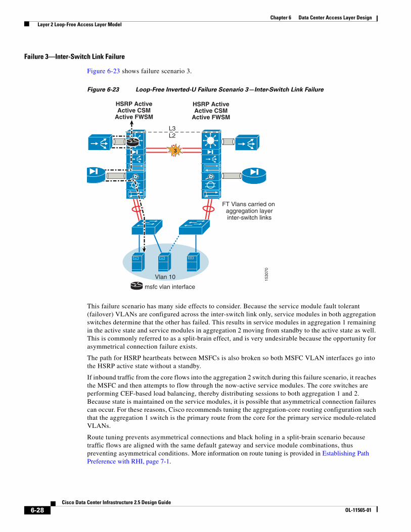
Figure 6-23 Loop-Free Inverted-U Failure Scenario 3—Inter-Switch Link Failure
This failure scenario has many side effects to consider. Because the service module fault tolerant (failover) VLANs are configured across the inter-switch link only, service modules in both aggregation switches determine that the other has failed. This results in service modules in aggregation 1 remaining in the active state and service modules in aggregation 2 moving from standby to the active state as well. This is commonly referred to as a split-brain effect, and is very undesirable because the opportunity for asymmetrical connection failure exists.
The path for HSRP heartbeats between MSFCs is also broken so both MSFC VLAN interfaces go into the HSRP active state without a standby.
If inbound traffic from the core flows into the aggregation 2 switch during this failure scenario, it reaches the MSFC and then attempts to flow through the now-active service modules. The core switches are performing CEF-based load balancing, thereby distributing sessions to both aggregation 1 and 2. Because state is maintained on the service modules, it is possible that asymmetrical connection failures can occur. For these reasons, Cisco recommends tuning the aggregation-core routing configuration such that the aggregation 1 switch is the primary route from the core for the primary service module-related VLANs.
Route tuning prevents asymmetrical connections and black holing in a split-brain scenario because traffic flows are aligned with the same default gateway and service module combinations, thus preventing asymmetrical conditions. More information on route tuning is provided in Establishing Path Preference with RHI, page 7-1.
1530
70
msfc vlan interface
FT Vlans carried on aggregation layerinter-switch links
L3L2
Vlan 10
HSRP ActiveActive CSM
Active FWSM
HSRP ActiveActive CSM
Active FWSM
3
6-28Cisco Data Center Infrastructure 2.5 Design Guide
OL-11565-01

Chapter 6 Data Center Access Layer Design FlexLinks Access Model
Failure 4—Switch Power or Sup720 Failure (Non-redundant)
Figure 6-24 shows failure scenario 4.
Figure 6-24 Loop-Free Inverted-U Failure Scenario 4—Single Sup720 or Power Failure
In this failure scenario, the primary HSRP default gateway and active service modules transition to the aggregation 2 switch. Servers that are single attached to an access layer switch are black holed. NIC teaming can be used to prevent this failure.
The convergence characteristics of this failure scenario depend on HSRP and service module failover times. Because the HSRP failover time is expected to be under that of service modules, the actual convergence time depends on service module timer configurations. Test lab results show this convergence time to be ~5–6 seconds.
FlexLinks Access ModelFlexLinks are an alternative to the looped access layer topology. FlexLinks provide an active-standby pair of uplinks defined on a common access layer switch. After an interface is configured to be a part of an active-standby FlexLink pair, spanning tree is turned off on both links and the secondary link is placed in a standby state, which prevents it from being available for packet forwarding. FlexLinks operate in single pairs only, participate only in a single pair at a time, and can consist of mixed interface types with mixed bandwidth. FlexLinks are configured with local significance only because the opposite end of a FlexLink is not aware of its configuration or operation. FlexLinks also has no support for preempt, or an ability to return to the primary state automatically after a failure condition is restored.
1530
71
FT Vlans carried on aggregation layerinter-switch links
Black hole server
msfc vlan interface
Vlan 10
HSRP ActiveActive CSM and FWSM
4
L3L2
6-29Cisco Data Center Infrastructure 2.5 Design Guide
OL-11565-01

Chapter 6 Data Center Access Layer Design FlexLinks Access Model
The main advantage of using FlexLinks is that there is no loop in the design and spanning tree is not enabled. Although this can have advantages in reducing complexity and reliance on STP, there is the drawback of possible loop conditions that can exist, which is covered in more detail later in this chapter. Other disadvantages are a slightly longer convergence time than R-PVST+, and the inability to balance traffic across both uplinks. Failover times measured using FlexLinks were usually under two seconds.
Note When FlexLinks are enabled on the access layer switch, it is locally significant only. The aggregation switch ports to which FlexLinks are connected do not have any knowledge of this state, and the link state appears as up and active on both the active and standby links. CDP and UDLD packets still traverse and operate as normal. Spanning tree is disabled (no BPDUs flow) on the access layer ports configured for FlexLink operation, but spanning tree logical and virtual ports are still allocated on the aggregation switch line card. VLANs are in the forwarding state as type P2P on the aggregation switch ports.
Figure 6-25 shows the FlexLinks access topology.
Figure 6-25 FlexLinks Access Topology
1530
72
L3L2
Vlan 10 Vlan 20
Root PrimaryHSRP Primary
Active Services
Root SecondaryHSRP SecondaryStandby Services
Row 2, Cabinet 3 Row 9, Cabinet 8
Vlan 10
FlexLink Active 10GE or 10GEC 802.1Q trunksFlexLink Standby LinkGE or EtherChannelBackup/NIC Teaming
6-30Cisco Data Center Infrastructure 2.5 Design Guide
OL-11565-01

Chapter 6 Data Center Access Layer Design FlexLinks Access Model
The configuration steps for FlexLinks are as follows. FlexLinks are configured only on the primary interface.
ACCESS1#conf tACCESS1(config-if)#interface tenGigabitEthernet 1/1ACCESS1(config-if)#switchport backup interface tenGigabitEthernet 1/2ACCESS1(config-if)#May 2 09:04:14: %SPANTREE-SP-6-PORTDEL_ALL_VLANS: TenGigabitEthernet1/2 deleted from all Vlans May 2 09:04:14: %SPANTREE-SP-6-PORTDEL_ALL_VLANS: TenGigabitEthernet1/1 deleted from all Vlans ACCESS1(config-if)#end
To view the current status of interfaces configured as FlexLinks:
ACCESS1#show interfaces switchport backup
Switch Backup Interface Pairs:
Active Interface Backup Interface State------------------------------------------------------------------------TenGigabitEthernet1/1 TenGigabitEthernet1/2 Active Up/Backup Standby
Note that both the active and backup interface are in up/up state when doing a “show interface” command:
ACCESS1#sh interfaces tenGigabitEthernet 1/1TenGigabitEthernet1/1 is up, line protocol is up (connected) Hardware is C6k 10000Mb 802.3, address is 000e.83ea.b0e8 (bia 000e.83ea.b0e8) Description: to_AGG1 MTU 1500 bytes, BW 10000000 Kbit, DLY 10 usec, reliability 255/255, txload 1/255, rxload 1/255 Encapsulation ARPA, loopback not set Keepalive set (10 sec) Full-duplex, 10Gb/s input flow-control is off, output flow-control is off ARP type: ARPA, ARP Timeout 04:00:00 Last input 00:00:09, output 00:00:09, output hang never Last clearing of "show interface" counters 00:00:30 Input queue: 0/2000/0/0 (size/max/drops/flushes); Total output drops: 0 Queueing strategy: fifo Output queue: 0/40 (size/max) 5 minute input rate 32000 bits/sec, 56 packets/sec 5 minute output rate 0 bits/sec, 0 packets/sec 1150 packets input, 83152 bytes, 0 no buffer Received 1137 broadcasts (1133 multicasts) 0 runts, 0 giants, 0 throttles 0 input errors, 0 CRC, 0 frame, 0 overrun, 0 ignored 0 watchdog, 0 multicast, 0 pause input 0 input packets with dribble condition detected 26 packets output, 2405 bytes, 0 underruns 0 output errors, 0 collisions, 0 interface resets 0 babbles, 0 late collision, 0 deferred 0 lost carrier, 0 no carrier, 0 PAUSE output 0 output buffer failures, 0 output buffers swapped out
ACCESS1#sh interfaces tenGigabitEthernet 1/2TenGigabitEthernet1/2 is up, line protocol is up (connected) Hardware is C6k 10000Mb 802.3, address is 000e.83ea.b0e9 (bia 000e.83ea.b0e9) Description: to_AGG2 MTU 1500 bytes, BW 10000000 Kbit, DLY 10 usec, reliability 255/255, txload 1/255, rxload 1/255 Encapsulation ARPA, loopback not set Keepalive set (10 sec)
6-31Cisco Data Center Infrastructure 2.5 Design Guide
OL-11565-01

Chapter 6 Data Center Access Layer Design FlexLinks Access Model
Full-duplex, 10Gb/s input flow-control is off, output flow-control is off ARP type: ARPA, ARP Timeout 04:00:00 Last input 00:00:51, output 00:00:03, output hang never Last clearing of "show interface" counters 00:00:33 Input queue: 0/2000/0/0 (size/max/drops/flushes); Total output drops: 0 Queueing strategy: fifo Output queue: 0/40 (size/max) 5 minute input rate 32000 bits/sec, 55 packets/sec 5 minute output rate 0 bits/sec, 0 packets/sec 1719 packets input, 123791 bytes, 0 no buffer Received 1704 broadcasts (1696 multicasts) 0 runts, 0 giants, 0 throttles 0 input errors, 0 CRC, 0 frame, 0 overrun, 0 ignored 0 watchdog, 0 multicast, 0 pause input 0 input packets with dribble condition detected 7 packets output, 1171 bytes, 0 underruns 0 output errors, 0 collisions, 0 interface resets 0 babbles, 0 late collision, 0 deferred 0 lost carrier, 0 no carrier, 0 PAUSE output 0 output buffer failures, 0 output buffers swapped outACCESS1#
Note that both the spanning-tree is no longer sending BPDUs in an effort to detect loops on interfaces in the FlexLink pair:
ACCESS1#sh spanning-tree interface tenGigabitEthernet 1/1no spanning tree info available for TenGigabitEthernet1/1ACCESS1#sh spanning-tree interface tenGigabitEthernet 1/2no spanning tree info available for TenGigabitEthernet1/2
CDP and UDLD packets are still transmitted across Flexlinks as shown below:
ACCESS1#show cdp neighborCapability Codes: R - Router, T - Trans Bridge, B - Source Route Bridge S - Switch, H - Host, I - IGMP, r - Repeater, P - Phone
Device ID Local Intrfce Holdtme Capability Platform Port IDAggregation-1.cisco.com Ten 1/1 156 R S WS-C6509 Ten 7/4Aggregation-2.cisco.com Ten 1/2 178 R S WS-C6509 Ten 7/4
ACCESS1#show udld neighbor Port Device Name Device ID Port ID Neighbor State---- ----------- --------- ------- --------------Te1/1 TBM06108988 1 Te7/4 Bidirectional Te1/2 SCA0332000T 1 Te7/4 Bidirectional ACCESS1#
Spanning Tree, HSRP, and Service Module DesignFlexLinks automatically disable spanning tree BPDUs on both the active and standby links, as noted in the preceding section. Cisco still recommends enabling spanning tree on the aggregation switches that are connected to FlexLink-enabled access switches. It is also desirable to align the spanning tree root, HSRP default gateway, and active service modules on the same aggregation switch just as recommended in looped access layer designs. This is shown in Figure 6-25. By aligning the primary access layer switch uplink directly to the same switch that is the primary default gateway and active service module/appliance, traffic flows are optimized. Otherwise, traffic flows can hop back and forth between aggregation switches, creating undesirable conditions and difficulty in troubleshooting.
6-32Cisco Data Center Infrastructure 2.5 Design Guide
OL-11565-01

Chapter 6 Data Center Access Layer Design FlexLinks Access Model
Implications Related to Possible Loop Conditions
Because spanning tree is disabled on FlexLinks, there is the possibility that a loop condition can exist in particular scenarios, such as a patch cable that is mistakenly connected between access layer switches that are configured for FlexLinks. This is shown in Figure 6-26.
Figure 6-26 Possible Loop Condition
Figure 6-26 demonstrates two possible loop conditions that can be introduced by configuration error or patch cable error. The first example demonstrates a connection between the aggregation switch and an access switch. This can be the result of an incorrect patch/uplink cable or simply the configuration of a separate link that is not part of the FlexLink channel group. Because STP BPDUs are not passed along the FlexLink path, a loop in the topology cannot be detected, and an endless replication of broadcast/multicast frames occurs that can have a very negative impact on the whole aggregation module. Note that RootGuard is ineffective in this scenario because Agg1 does not see a path to the root (Agg2) through the access switch with FlexLinks enabled.
The second example demonstrates a patch cable connection error between access switches.
If BPDU Guard is supported and enabled on access layer server ports, the port is automatically disabled when BPDUs are detected, as shown in the following console message:
ACCESS1#Apr 13 16:07:33: %SPANTREE-SP-2-BLOCK_BPDUGUARD: Received BPDU on port GigabitEthernet2/2 with BPDU Guard enabled. Disabling port.
1539
78vlan 6
Root PrimaryHSRP Primary
Active Services
Campus Core
Root SecondaryHSRP Primary
Backup Services
Po-2T7/4
T7/4
G2/1
Patch cableerror
G2/2
Po-3
BPDU-Guardcan prevent aloop condition
6-33Cisco Data Center Infrastructure 2.5 Design Guide
OL-11565-01
Chapter 6 Data Center Access Layer Design FlexLinks Access Model
Apr 13 16:07:33: %PM-SP-4-ERR_DISABLE: bpduguard error detected on Gi2/2, putting Gi2/2 in err-disable stateACCESS1#sh int g2/2GigabitEthernet2/2 is administratively down, line protocol is down (disabled)
If BPDU Guard is not supported or is not enabled on access layer server ports, a loop condition occurs. This loop condition endlessly forwards multicast and broadcast packets through the aggregation 1 switch and back through the access switches via the patch cable link that now extends between them. This could create negative conditions that affect all servers connected to this aggregation module.
Note Because spanning tree BPDUs are not passed from the access layer switch when using FlexLinks, cabling or configuration errors can create a loop condition with negative implications. Although cabling mistakes such as these might be considered rare, the degree of change control in your data center environment can be the barometer in determining whether Flexlinks are a proper solution.
Failure Scenarios
The level of resiliency that is incorporated into the access layer design can vary based on the model used. Other features such as route health injection and route tuning can influence this. The four main failure scenarios that can occur in a looped access design are covered in this section. Understanding the amount of exposure in these scenarios helps to determine the best access layer design selection.
6-34Cisco Data Center Infrastructure 2.5 Design Guide
OL-11565-01
Chapter 6 Data Center Access Layer Design FlexLinks Access Model
Failure 1—Access Layer Uplink Failure
Figure 6-27 shows failure scenario 1.
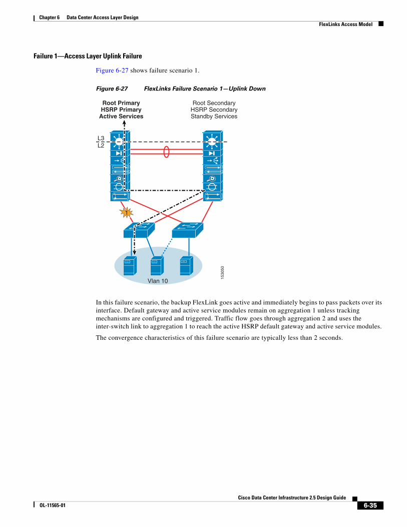
Figure 6-27 FlexLinks Failure Scenario 1—Uplink Down
In this failure scenario, the backup FlexLink goes active and immediately begins to pass packets over its interface. Default gateway and active service modules remain on aggregation 1 unless tracking mechanisms are configured and triggered. Traffic flow goes through aggregation 2 and uses the inter-switch link to aggregation 1 to reach the active HSRP default gateway and active service modules.
The convergence characteristics of this failure scenario are typically less than 2 seconds.
1530
50
L3L2
Vlan 10
Root PrimaryHSRP Primary
Active Services
Root SecondaryHSRP SecondaryStandby Services
1
6-35Cisco Data Center Infrastructure 2.5 Design Guide
OL-11565-01

Chapter 6 Data Center Access Layer Design FlexLinks Access Model
Failure 2—Service Module Failure (using CSM One-arm and FWSM Transparent Mode)
Figure 6-28 shows failure scenario 2.
Figure 6-28 FlexLinks Failure Scenario 2—Service Modules
In this failure scenario, there is no FlexLink convergence and the primary default gateway remains active on the aggregation 1 switch. The backup service module moves to the active state on aggregation 2 because it no longer receives hello packets from the failed active service module and times out.
Figure 6-28 shows the following two failure instances:
• 2.1 (FWSM failure)—Traffic flow goes through aggregation 1 and across the inter-switch link to aggregation 2, through the now-active FWSM module context, and back across the inter-switch link to the active HSRP default gateway on the aggregation 1 MSFC. Because the CSM is still active in aggregation 1, return traffic flow is directed to the CSM based on the PBR configuration on the MSFC VLAN interface and on to the client via the core.
• 2.2 (CSM failure)—Traffic flow goes through aggregation 1, through the active FWSM module context in aggregation 1, and to the MSFC VLAN interface. The MSFC VLAN interface PBR configuration forces return CSM traffic to travel across the inter-switch link to aggregation 2 and through the now-active CSM module. Because the active default gateway of the CSM server VLAN is still active on aggregation 1, the traffic must flow back across the inter-switch link to the MSFC on aggregation 1 and then on to the client via the core.
1530
73
msfc vlan interface
L3L2
Vlan 10
Root PrimaryHSRP Primary
Active CSM
Root PrimaryHSRP Secondary
Active FWSM
Vlan 10
Root PrimaryHSRP PrimaryActive FWSM
Root PrimaryHSRP Secondary
Active CSM
22L3L2
21
6-36Cisco Data Center Infrastructure 2.5 Design Guide
OL-11565-01

Chapter 6 Data Center Access Layer Design FlexLinks Access Model
The convergence characteristics of these failure scenarios depend on the service module(s) failover time. The recommended service module failover timer configurations are as follows:
• CSM:
module ContentSwitchingModule 3 ft group 1 vlan 102 priority 20 heartbeat-time 1 failover 3 preempt
• FWSM:
Unit Poll frequency 500 milliseconds, holdtime 3 secondsInterface Poll frequency 3 seconds
Test lab results show that average service module failover times with these values is under ~5 seconds.
Failure 3—Inter-Switch Link Failure
Figure 6-29 shows failure scenario 3.
Figure 6-29 FlexLinks Failure Scenario 3—Inter-Switch Link Failure
FlexLinks do not converge in this failure scenario.
With the inter-switch link down, HSRP multicast hello messages no longer have a path between aggregation 1 and 2, so HSRP goes into an active state on both switches for all VLANs.
Service modules in both aggregation switches determine that the other has failed and become active (this is referred to as a split-brain effect).
1530
74
L3L2
Vlan 10
Root PrimaryHSRP Active
Active Services
Root SecondaryHSRP Active
Active Services
3
6-37Cisco Data Center Infrastructure 2.5 Design Guide
OL-11565-01

Chapter 6 Data Center Access Layer Design FlexLinks Access Model
If inbound traffic from the core flows into the aggregation 2 switch during this failure scenario, it attempts to flow through the now-active service modules and stops because the path to the servers is blocked by a standby FlexLink. For these reasons, Cisco recommends tuning the aggregation-core routing configuration such that the aggregation 1 switch is the primary route advertised to the core for the primary service module-related VLANs.
Route tuning helps to prevent asymmetrical connections and black holing in a split-brain scenario because traffic flows are aligned with the same default gateway and service module combination, preventing asymmetrical conditions.
Failure 4—Switch Power or Sup720 Failure (Non-redundant)
Figure 6-30 shows failure scenario 4.
Figure 6-30 FlexLinks Failure Scenario 4—Switch Power of Sup720 Failure
In this failure scenario, the active FlexLinks, primary default gateway, and active service modules transition to the aggregation 2 switch.
The convergence characteristics of this failure scenario depend on FlexLink failure detection, HSRP failover, and service module failover times. Because the FlexLink and HSRP failover times are expected to be under that of service modules, the actual convergence time depends on service module timer configurations.
1530
75
L3L2
Vlan 10
Root SecondaryHSRP Active
Active Services
4
6-38Cisco Data Center Infrastructure 2.5 Design Guide
OL-11565-01

Chapter 6 Data Center Access Layer Design Using EtherChannel Min-Links
Using EtherChannel Min-LinksEtherChannel Min-Links is a new feature as of the Cisco 12.2.18 SXF IOS Release. EtherChannel Min-Links permit you to designate the minimum number of member ports that must be in the link-up state and bundled in an LACP EtherChannel for a port channel interface to be in a link-up state. In the data center access layer, this can be useful in making sure that a higher bandwidth uplink path is chosen as the active path. For example, consider the diagram in Figure 6-31.
Figure 6-31 Using EtherChannel Min-Links
In the above example,4G EtherChannels connect the access layer switch to both aggregation layer switches. A failure has occurred that has taken down two of the port members on the EtherChannel to the aggregation 1 switch. Because two members of the port channel are still up, the port channel itself remains up and server traffic uses this path as normal, although it is a path with less available bandwidth. With EtherChannel Min-Links, you can designate a minimum number of required ports that must be active or the port channel is taken down. In this example, if EtherChannel Min-Links are set to 3, the port channel is taken down and server traffic is forced to use the higher 4G bandwidth path towards the aggregation 2 switch.
The EtherChannel Min-Links feature requires the LACP EtherChannel protocol to be used. The access layer topology can consist of looped, loop-free, or FlexLink models. The Min-Links feature works at the physical interface level and is independent of spanning tree path selection.
1539
79
Port-Channel 2with 2 portsdown (2G)
Campus Core
Min-Links set to 3 wouldbring the port-channel
down, forcing all traffic touse higher bandwidth path
via Agg2
Port-Channel3 with all
links up (4G)
6-39Cisco Data Center Infrastructure 2.5 Design Guide
OL-11565-01

Chapter 6 Data Center Access Layer Design Using EtherChannel Min-Links
Consider the following when deciding whether Min-Links should be used:
• Active/standby service modules are used—If active services are primarily on the aggregation 1 switch, a failure that forces Min-Links to use the path to aggregation 2 will likely cause all traffic to also traverse the inter-switch link between the aggregation switches.
• Looped topologies with spanning tree—If a looped access topology is used, it is possible to provide a similar capability by using the spanning-tree pathcost method long global option. This permits spanning tree to use larger cost values when comparing the cost of different paths to root, which in turn can differentiate the cost value of various paths when a port member fails.
• Dual failures—With Min-Links, it is possible to have a situation where if both EtherChannels do not have the minimum required port members, both uplinks would be forced down, which would black-hole all connected servers.
The configuration steps for EtherChannel Min-Links are as follows:
ACCESS2#conf tEnter configuration commands, one per line. End with CNTL/Z.ACCESS2(config)#interface port-channel 2ACCESS2(config-if)#port-channel ? min-links Minimun number of bundled ports needed to bring up this port channelACCESS2(config-if)#port-channel min-links ? <2-8> The minimum number of bundled ports needed before this port channel can come up.ACCESS2(config-if)#port-channel min-links 3ACCESS2(config-if)#end
6-40Cisco Data Center Infrastructure 2.5 Design Guide
OL-11565-01