Data Communications & Computer Networks, Second Edition1 Chapter 7 Local Area Networks: The Basics.
Upload
maxim-bobbyCategory
view
213download
0
Data and Computer Communications
Chapter 15 – Local Area Network Overview
Local Area Networks (LANs)
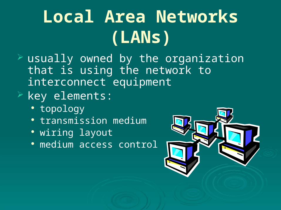
usually owned by the organization that is using the network to interconnect equipment
key elements: topology transmission medium wiring layout medium access control
LAN Topologies
In the context of a communication network, the term topology refers to the way in which the end points, or stations, attached to the network are interconnected.
Historically common topologies for LANs are bus, tree, ring, and star .

LAN Topologies

Bus and Tree
Bus:
• stations attach through tap to bus
• full duplex allows transmission and reception
• transmission propagates throughout medium
• heard by all stations• terminator at each
end
Tree:
• a generalization of bus
• branching cable with no closed loops
• tree layout begins at headend and branches out
• heard by all stations
Bus Topology All stations attach, through appropriate hardware
interfacing known as a tap, directly to a linear transmission medium, or bus.
Full-duplex operation between the station and the tap allows data to be transmitted onto the bus and received from the bus.
A transmission from any station propagates the length of the medium in both directions and can be received by all other stations.
At each end of the bus is a terminator, which absorbs any signal, removing it from the bus.

Tree topology The tree topology is a generalization of the bus
topology. The transmission medium is a branching cable with
no closed loops. The tree layout begins at a point known as the
headend. One or more cables start at the headend, and each of
these may have branches. The branches in turn may have additional branches to
allow quite complex layouts. Again, a transmission from any station propagates throughout the medium and can be received by all other stations.

Frame Transmissionon Bus LAN

Ring Topology
a closed loop of repeaters joined by point-to-point links
receive data on one link & retransmit on another links unidirectional stations attach to repeaters
data transmitted in frames circulate past all stations destination recognizes address and copies frame frame circulates back to source where it is removed
medium access control determines when a station can insert frame

Frame Transmission
Ring LAN

Star Topology
each station connects to common central node usually via two point-to-point link
• one for transmission and one for reception
• operate in broadcast fashion• physical star, logical bus• only one station can transmit at a time (hub)• can act as frame switch
central node
Bus LAN Transmission Media
cont…
• early LANs used voice grade cable• scaling up for higher data rates not practical
twisted pair
• uses digital signaling• original Ethernet
baseband coaxial cable

Bus LAN Transmission Media
only baseband coaxial cable has achieved widespread use
• used in cable TV systems• analog signals at radio and TV frequencies• expensive, hard to install and maintain
broadband coaxial cable
• expensive taps• better alternatives available
optical fiber

Ring and Star Topologies
Ring
• very high speed links over long distances
• potential of providing best throughput
• single link or repeater failure disables network
Star
• uses natural layout of wiring in building
• best for short distances• high data rates for small
number of devices
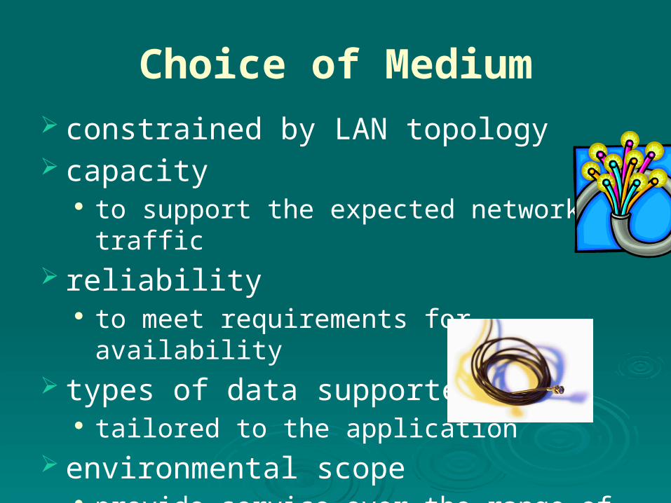
Choice of Medium constrained by LAN topology capacity
to support the expected network traffic reliability
to meet requirements for availability types of data supported
tailored to the application environmental scope
provide service over the range of environments

LAN PROTOCOL ARCHITECTURE
The architecture of a LAN is best described in terms of a layering of protocols that organize the basic functions of a LAN.
This section opens with a description of the standardized protocol architecture for LANs, which encompasses physical, medium access control (MAC), and logical link control (LLC) layers.
The physical layer encompasses topology and transmission medium,

LAN Protocol Architecture

IEEE 802 Layers
Physical Layer Encoding / decoding of signals preamble generation / removal bit transmission / reception transmission medium and topology

IEEE 802 Layers
Logical Link Control Layer (LLC)
provide interface to higher levels
perform flow and error control
Media Access Control
on transmit assemble data into frame
on reception disassemble frame, perform address recognition and error detection
govern access to transmission medium
for same LLC, may have several MAC options
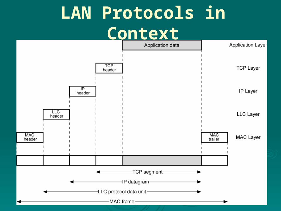
LAN Protocols in Context

Logical Link Control
transmission of link level PDU protocol data unit (PDU). s between stations
must support multi-access, shared medium
relieved of some details of link access by the MAC layer
addressing involves specifying source and destination LLC users referred to as service access points (SAPs)

LLC Protocol
modeled after HDLC (high-level data link control)
asynchronous balanced mode connection mode (type 2) LLC service
unacknowledged connectionless service using unnumbered information PDUs (type 1)
acknowledged connectionless service using 2 new unnumbered PDUs (type 3)
permits multiplexing using LSAPs

MAC Frame Format

Bridges
connects similar LANs with identical physical and link layer protocols
minimal processing can map between MAC formats reasons for use:
reliability performance security geography
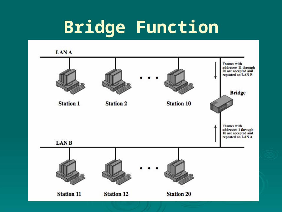
Bridge Function
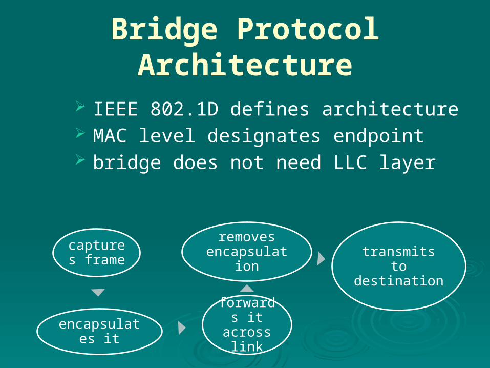
Bridge Protocol Architecture
IEEE 802.1D defines architecture MAC level designates endpoint bridge does not need LLC layer
captures frame
encapsulates it
forwards it across
link
removes encapsulation transmits to
destination

Connection of Two LANs
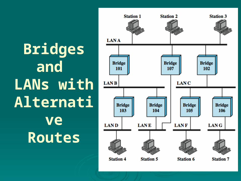
Bridges and
LANs withAlternative
Routes
Fixed Routing
simplest and most common suitable for Internets that are stable a fixed route is selected for each pair of LANs
• usually least hop route only changed when topology changes widely used but limited flexibility

Spanning Tree
bridge automatically develops routing table automatically updates routing table in
response to changing topology
algorithm consists of three mechanisms:
frame forwarding address learning loop resolution

Address Learning can preload forwarding database when frame arrives at port X, it has come from
the LAN attached to port X use source address to update forwarding
database for port X to include that address have a timer on each entry in database if timer expires, entry is removed each time frame arrives, source address
checked against forwarding database if present timer is reset and direction recorded if not present entry is created and timer set

Spanning Tree Algorithm address learning works for tree layout if there
are no alternate routes in the network alternate route means there is a closed loop
for any connected graph there is a spanning tree maintaining connectivity with no closed loops
algorithm must be dynamic
• each bridge assigned unique identifier• cost assigned to each bridge port• exchange information between bridges to find spanning tree• automatically updated whenever topology changes
IEEE 802.1 Spanning Tree Algorithm:

Interconnecting LANs - Hubs
active central element of star layout each station connected to hub by two UTP lines hub acts as a repeater limited to about 100m by UTP properties optical fiber may be used out to 500m physically star, logically bus transmission from a station seen by all others if two stations transmit at the same time have a
collision

Two Level Hub Topology
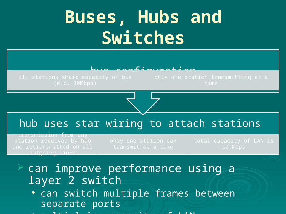
Buses, Hubs and Switches
can improve performance using a layer 2 switch can switch multiple frames between separate ports multiplying capacity of LAN
hub uses star wiring to attach stations transmission from any station
received by hub and retransmitted on all outgoing lines
only one station can transmit at a time total capacity of LAN is 10 Mbps
bus configurationall stations share capacity of bus (e.g. 10Mbps) only one station transmitting at a time

Shared Medium Bus and
Hub

Layer 2 Switch Benefits
no change to attached devices to convert bus LAN or hub LAN to switched LAN
e.g. Ethernet LANs use Ethernet MAC protocol have dedicated capacity equal to original LAN
assuming switch has sufficient capacity to keep up with all devices
scales easily additional devices attached to switch by increasing
capacity of layer 2

Types of Layer 2 Switches
store-and-forward switch
accepts frame on input line, buffers briefly, routes to destination port
see delay between sender and receiver
boosts overall integrity
cut-through switch use destination
address at beginning of frame
switch begins repeating frame onto output line as soon as destination address is recognized
highest possible throughput
risk of propagating bad frames

Two types of layer 2 switches are available as commercial products:
Store-and-forward switch: The layer 2 switch accepts a frame on an input line, buffers it briefly, and then routes it to the appropriate output line.
Cut-through switch: The layer 2 switch takes advantage of the fact that the destination address appears at the beginning of the MAC (medium access control) frame. The layer 2 switch begins repeating the incoming frame onto the appropriate output line as soon as the layer 2 switch recognizes the destination address.

Layer 2 Switch vs. Bridge
differences between switches & bridges: layer 2 switch can be
viewed as full-duplex hub
incorporates logic to function as multiport bridge
new installations typically include layer 2 switches with bridge functionality rather than bridges
Bridge
frame handling done in software
analyzes and forwards one
frame at a time
uses store-and-forward operation
Switch
performs frame forwarding in
hardware
can handle multiple frames
at a time
can have cut-through operation

Virtual LANs (VLANs)
subgroup within a LAN created by software combines user stations and network
devices into a single broadcast domain functions at the MAC layer router required to link VLANs physically dispersed but maintains group
identity

A VLAN Configuration

Defining VLANs
broadcast domain consisting of a group of end stations not limited by physical location and communicate as if they were on a common LAN
membership by: port group MAC address protocol information

Communicating VLAN Membership
Switches need to know VLAN membership
configure information manually network management signaling protocol frame tagging (IEEE802.1Q)
Summary
LAN topologies and transmission media bus, tree, ring, star
LAN protocol architecture IEEE 802, LLC, MAC
bridges, hubs, layer 2 switches virtual LANs