DAS-000066-01 sPDS-480ca 75v Product Guide
12
sPDS-480ca Power / data supply for large-scale Ethernet installations
Transcript of DAS-000066-01 sPDS-480ca 75v Product Guide

sPDS-480caPower / data supply for large-scale Ethernet installations

sPDS-480ca Product Guide2
Versatile Power and Data for Large-Scale Ethernet InstallationsProvides power to up to 240 low-voltage fixtures. Features include short-circuit protection, on-board controls, and diagnostic functions to assist with the proper operation of Philips Color Kinetics lighting systems.
sPDS-480caPower / data supply for large-scale Ethernet installations
sPDS-480ca 24 V delivers 480 watts of output via eight 60-watt ports. The 7.5 V version delivers 480 watts of output via 16 30-watt ports. Both automatically accommodate input voltages ranging from 100 VAC to 240 VAC. Short-circuit protection prevents device failure due to incorrectly wired fixtures. The standard IEC power inlet accepts both North American and international power cables.
With onboard controls, sPDS-480ca incorporates automatic fixture discovery and testing, eliminating the need for additional addressing tools or software. sPDS-480ca features a backlit LCD for easy menu viewing.
Housed in a 2U rack-mountable enclosure, sPDS-480ca includes rack handles and surface-mount brackets, for versatile mounting options.
Over-temperature detection and selectable shutdown options protect sPDS-480ca against operation beyond its rated temperature specification. Variable-speed fans keep noise levels low and include user serviceable air filters.
Compatible Fixtures
Device Fixture Max. Quantity Per sPDS-480ca
Max. Quantity Per Output Port
sPDS-480ca 7.5 ViColor Flex MX 960 nodes 60 nodes
iColor Tile MX 6 tiles 1/2 tile
sPDS-480ca 24 V
eW Flex SLX 480 nodes 60 nodes
iColor Flex LMX 480 nodes 60 nodes
iColor Cove EC 7 in 240 fi xtures 30 fi xtures
iColor Cove EC 12 in 240 fi xtures 30 fi xtures
iColor Cove QLX 6 in 240 fi xtures 30 fi xtures
iColor Cove QLX 12 in 160 fi xtures 20 fi xtures
sPDS-480ca is a power / data supply designed for large-scale Ethernet LED lighting installations using low-voltage fixtures from Philips Color Kinetics. sPDS-480ca includes 7.5 V and 24 V versions to meet the power requirements of different fixtures.

sPDS-480ca Product Guide 3
100-240VAC, 6A - 2.5A, 50-60 Hz
sPDS-480ca 24VITEM# 109-000026-00
8765
sPDS-480ca 24V
1 2 3 4
POWER/DATA24VDC
Ethernet
to Ethernet Switch
IEC Power Inlet
and US Cable set
Fixture Leader Cables
Power Switch
Onboard Push-button Controls
Menu LCD
Ordering Information
Use Item Number when ordering in North America.
Item Item Number Philips 12NC
sPDS-480ca 7.5 V 109-000022-00 910503700107
sPDS-480ca 24 V 109-000026-00 910503700110
Specifi cations Due to continuous improvements and innovations, specifications may change without notice.
Item Specifi cation Details
Electrical
Input Voltage 100 – 240 VAC, auto-switching, 50 / 60 Hz
Maximum Input Current 6 A at 100 VAC, 5 A at 120 VAC, 2.5 A at 240 VAC
Power Output
sPDS-480ca 7.5 V 7.5 VDC, 480 W (30 W per power port)
sPDS-480ca 24 V 24 VDC, 480 W (60 W per power port)
Fuse Rating
sPDS-480ca 7.5 (16) 5 A, 125 V, 5 x 20 fast blow fuses
sPDS-480ca 24 V (8) 4 A, 125 V, 5 x 20 fast blow fuses
Physical
Dimensions(Height x Width x Depth) 3.5 x 19 x 18 in (89 x 483 x 457 mm)
Weight 26.5 lb (12 kg)
Construction 2U rack and surface-mountable chassis
Finish Black matte
Connectors
Data RJ45 input connector
Power OutputsPDS-480ca 7.5 V (8) 4-pin output receptacles
sPDS-480ca 24 V (16) 4-pin output receptacles
Power Input IEC 320 receptacle type C13, locking clamp
Temperature Ranges14° – 122° F (-10° – 50° C) Operating14° – 122° F (-10° – 50° C) Startup-40° – 176° F (-40° – 80° C) Storage
Humidity 0 – 95%, non-condensing
Cooling Air cooled. (2) speed-confi gurable fans, with serviceable air fi lters
Airfl ow Front panel input, back panel output
Heat Dissipation 25% of total power input
Data Input Source Philips full range of Ethernet controllers, or third-party KiNET-compatible* Ethernet controllers
Certifi cation and Safety
Certifi cation UL / cUL, CE, PSE
Classifi cation UL Class 2 power supply
Environment Dry Location, IP20
19.0 in
sPDS-480ca 24V
Ethernet
(483 mm)
1.8 in(46 mm)
3.5 in(89 mm)
16.4 in(417 mm)
18.0 in(457 mm)
17.0 in(432 mm)
Dimensions: Rack Mount Configuration
sPDS-480ca 24V
Ethernet
19.0 in(483 mm)
18.4 in(467 mm)
12.3 in(312 mm)
10.6 in(269 mm)
1.8 in(46 mm)
2.9 in(74 mm)
10.6 in(269 mm)
13.5 in(343 mm)
3.0 in(76 mm)
2.3 in(58mm)
Dimensions: Surface Mount Configuration
* KiNET is the Ethernet lighting protocol from Philips Color Kinetics.
Included in the box
sPDS-480ca power / data supply(2) Rack mount bracket and handles
(2) Surface mount brackets
(8) Screws, 0.7 X 10 mm
(8) Lock washers
100 VAC T VAC 50Hz-60Hz, 8A Max.
LISTED78GF
POWER/D ATA7.5VDC
sPDS-480ca 7.5VITEM# 109-000022-00
121110987654321 13 14 15 16
sPDS-480ca 24 V sPDS-480ca 7.5 V

sPDS-480ca Product Guide4
InstallationsPDS-480ca is a power / data supply designed for large-scale Ethernet LED lighting installations using low-voltage fixtures from Philips Color Kinetics. sPDS-480ca delivers 480 watts of output and automatically accommodates input voltages ranging from 100 VAC to 240 VAC. Onboard controls incorporate automatic fixture discovery, addressing, and testing. sPDS-480ca is available in 7.5 V and 24 V versions to meet the power requirements of different fixtures.
Owner / User ResponsibilitiesIt is the responsibility of the contractor, installer, purchaser, owner, and user to install, maintain, and operate sPDS-480ca in such a manner as to comply with all applicable codes, state and local laws, ordinances, and regulations. Consult with the appropriate electrical inspector to ensure compliance.
Plan the InstallationTo streamline installation and ensure accurate confi guration, start with a layout or a lighting design plan that shows the physical layout of the installation and identifi es the locations of all lighting fi xtures, power / data supplies, controllers, switches, and cables.
Ethernet Confi gurationsPDS-480ca is designed for use in Ethernet networks. Typical Ethernet installations with Philips Color Kinetics LED fixtures include an Ethernet switch, an Ethernet controller such as Light System Manager or Video System Manager Pro, Ethernet Controller Keypads for light show triggering, and one or more sPDS-480ca devices.
In an Ethernet environment, each Philips Color Kinetics power / data supply has a unique IP address. Each fixture connected to the device is automatically assigned unique identifiers that controllers use to identify and manage the fixture.
Maximum data cable lengths are 328 ft (100 m) between Ethernet devices without a repeater. The number of fixtures that each sPDS-480ca unit can support depends on the power requirements of the specifi c fi xtures that you are using. See the table on the following page for the maximum quantities of each fi xture that you can connect per device.
sPDS-480ca 7.5 V
LightSystemManager
EthernetSwitch
PC
iColor Flex MX
E Refer to the sPDS-480ca Installation Instructions for specifi c warning and caution statements.
PDS-480 caEthernetSwitch
328 ft (100 m) Max
Typical Ethernet Installation
E To connect sPDS-480ca to a DMX Controller such as iPlayer 3 or a third-party controller, use the Multi-Protocol Converter with a Power-over-Ethernet (PoE) injector or PoE switch.

sPDS-480ca Product Guide 5
Electrical Confi guration GuidelinesLinear fi xtures such as iColor Cove EC and iColor Cove QLX can be installed in series using the fi xtures’ end-to-end connectors. You can install one string of Flex fi xtures per port. iColor Tile MX requires two ports per fi xture for a total of eight tiles on a 7.5 V sPDS-480ca.
Each sPDS-480ca connects to line power with a standard IEC inlet and power cable, which can be secured using a locking clamp located on the back of the device’s housing.
The sPDS-480ca should be installed in a dry location.
Assemble Additional ItemsThe following items are required to mount and connect the sPDS-480ca:
• The 2 included rack mount brackets with handles (if rack mounting)
• 4 screws (typically 10-32) and lock washers suitable for mounting the device to a rack (if rack mounting)
• The 4 included surface mount brackets (if surface mounting)
• 16 screws suitable for the surface (if surface mounting)
• A power screwdriver (if surface mounting)
• A Phillips screwdriver (if surface mounting)
• The 8 included screws, 0.7 x 10 mm
• The 8 included lock washers
• The included IEC power cable
• CAT 5e or better data cable, as required
You must also have access to a dedicated Ethernet network, an Ethernet switch, and a controller that is compatible with a KiNET-based lighting system, such as Philips Color Kinetics Light System Manager, Video System Manager Pro, or ColorDial Pro.
Inspect sPDS-480ca and AccessoriesCarefully inspect the box containing the sPDS-480ca and the contents for any damage that may have occurred in transit.
Device Fixture Max. Quantity Per sPDS-480ca
Max. Quantity Per Output Port
sPDS-480ca 7.5 ViColor Flex MX 960 nodes 60 nodes
iColor Tile MX 6 tiles 1/2 tile
sPDS-480ca 24 V
eW Flex SLX 480 nodes 60 nodes
iColor Flex LMX 480 nodes 60 nodes
iColor Cove EC 7 in 240 fi xtures 30 fi xtures
iColor Cove EC 12 in 240 fi xtures 30 fi xtures
iColor Cove QLX 6 in 240 fi xtures 30 fi xtures
iColor Cove QLX 12 in 160 fi xtures 20 fi xtures
Compatible Fixtures
Included in the boxsPDS-480ca power / data supply
IEC power cable
(8) Lock washers
(2) Rack mount brackets with handles
(8) Screws, 0.7 X 10 mm
(2) Surface mount brackets
sPDS-480ca 24V
iColor Cove QLX
EthernetSwitch
PC
LightSystemManager
Typical iColor Cove QLX Installation
E KiNET Ethernet is the high performance network protocol engineered by Philips Color Kinetics for LED lighting control.
sPDS-480ca Product Guide6
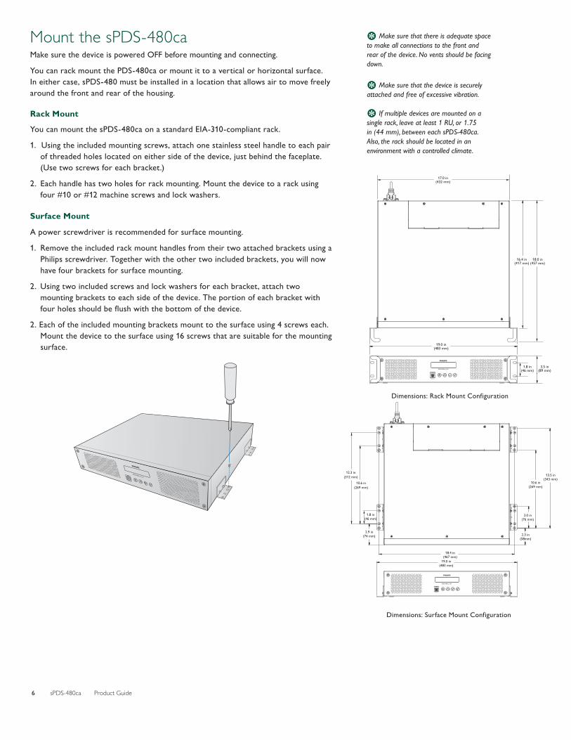
Mount the sPDS-480caMake sure the device is powered OFF before mounting and connecting.
You can rack mount the PDS-480ca or mount it to a vertical or horizontal surface. In either case, sPDS-480 must be installed in a location that allows air to move freely around the front and rear of the housing.
Rack Mount
You can mount the sPDS-480ca on a standard EIA-310-compliant rack.
1. Using the included mounting screws, attach one stainless steel handle to each pair of threaded holes located on either side of the device, just behind the faceplate. (Use two screws for each bracket.)
2. Each handle has two holes for rack mounting. Mount the device to a rack using four #10 or #12 machine screws and lock washers.
Surface Mount
A power screwdriver is recommended for surface mounting.
1. Remove the included rack mount handles from their two attached brackets using a Philips screwdriver. Together with the other two included brackets, you will now have four brackets for surface mounting.
2. Using two included screws and lock washers for each bracket, attach two mounting brackets to each side of the device. The portion of each bracket with four holes should be fl ush with the bottom of the device.
2. Each of the included mounting brackets mount to the surface using 4 screws each. Mount the device to the surface using 16 screws that are suitable for the mounting surface. 19.0 in
sPDS-480ca 24V
Ethernet
(483 mm)
1.8 in(46 mm)
3.5 in(89 mm)
16.4 in(417 mm)
18.0 in(457 mm)
17.0 in(432 mm)
Dimensions: Rack Mount Configuration
sPDS-480ca 24V
Ethernet
19.0 in(483 mm)
18.4 in(467 mm)
12.3 in(312 mm)
10.6 in(269 mm)
1.8 in(46 mm)
2.9 in(74 mm)
10.6 in(269 mm)
13.5 in(343 mm)
3.0 in(76 mm)
2.3 in(58mm)
Dimensions: Surface Mount Configuration
E If multiple devices are mounted on a single rack, leave at least 1 RU, or 1.75 in (44 mm), between each sPDS-480ca. Also, the rack should be located in an environment with a controlled climate.
E Make sure that there is adequate space to make all connections to the front and rear of the device. No vents should be facing down.
E Make sure that the device is securely attached and free of excessive vibration.

sPDS-480ca Product Guide 7
Connect the sPDS-480ca to Line Power1. Connect the IEC power cable to the inlet in the back of the sPDS-480ca.
2. To secure the cord, tighten the locking clamp around the inlet with a Phillips screwdriver.
3. Connect the power cable to line power.
Connect the sPDS-480ca to FixturesMake sure the device is powered OFF before connecting to fixtures.
1. Connect the leader cables or Flex strands to an available port on the back of the device. Ports are labeled 1 through 8.
2. Power the device ON.
Note that before you can control the connected fixtures, you must discover fixtures using either the sPDS-480ca device’s on-board menu (described in the next section), QuickPlay Pro software, or the discover functionality in the software for Light System Manager or Video System Manager.
Discovering fi xtures fi nds the quantity of connected fi xtures and registers them on your power / data supply.
E You can download QuickPlay Pro from www.colorkinetics.com/support/ addressing/

sPDS-480ca Product Guide8
Using the sPDS-480ca On-Board MenusPDS-480ca has a navigable LCD screen with three menu levels.
Menu LevelDescription
1 2 3
View Status
Network
NET: IP Address ... Displays device’s current IP address MAC Address Displays device’s MAC address
Data Rate Displays an estimate of network bandwidth currently used by the device
Serial Number Displays the device’s serial numberLights Lights Per Port Displays the nodes scanned for each port
Temperature
Internal Temp Displays an estimate of the device’s internal temperature
Min / Max Temp Displays minimum and maximum temperature since device was last turned on
Fan Status Displays whether fan is on or off, and speed of fan as percentage of maximum
Configure
Set IP Address 10.X.X.X Modifies the device’s IP address
Scan Lights Press Select Discovers and counts the nodes connected to each port
Fan Settings
Low Sets fans to run continuously at the selected speed. If temperature rise is detected, fan speed automatically switches to High until the temperature reaches a safe level.
Medium
High
Auto* Fan speed automatically adjusts based on the detected temperature
Thermal Settings
Turn Lights Off* If device overheats, lights turn offRamp Down Lights If device overheats, lights smoothly fade outStay On If device overheats, lights remain on
LCD Backlight
BrightSets the brightness of the device’s LCD backlightMedium*
Dim
Auto-Dim Dims the LCD backlight when no buttons have been pressed for 15 seconds
Restore Defaults Press Select
Restores factory default settings for LCD Backlight, Fan Settings, and Thermal Settings. Network configuration is unaffected.
TestTest Lights
All Off Turns off all nodesAll Red
Turns on all channels of a particular colorAll GreenAll BlueAll White
Rainbow Cycles through red, green, and blue, showing waves of different colors across all nodes
Single Port
Turns on nodes connected to one port. Press Select to begin test. Press the Down button to begin automatically cycling through the device’s ports. Press the Down button again to manually cycle through the device’s ports.
Single Light
Turns on a single node. Press Select to begin test. Press the Down button to begin automatically cycling through the connected nodes. Press the Down button again to manually cycle through the connected nodes.
Test Fans on Full Turns on the device’s two fans at full speed
Reset System Press Select
Resets the device. This has the same effect as powering it down and turning it back on. Your configured settings are unaffected.
About Press Select Displays system information, including unit model, serial number, and firmware revision number
To navigate the on-board menu:
• Press the Up and Down buttons () to move up and down in the current menu’s set of options.
• Press the Select button () to select a menu item or display its submenu.
• Press the Cancel button () to return to the previous menu level.
sPDS-480ca 7.5 V
Ethernet
* Default settings.

sPDS-480ca Product Guide 9
Scanning LightsYou can scan the nodes attached to the device’s ports to discover fi xtures and confi rm that they are connected and receiving data. The discovery determines the quantity of connected nodes and registers them on your power / data supply. The power / data supply then assigns DMX addresses to uniquely identify each node, which controllers can use to perform video and light shows.
► To scan lights:1. Press Select to activate the sPDS-480ca menu.2. Select Confi gure.3. Select Scan Lights. The LCD menu displays “scanning...”4. When scanning fi nishes, you can confi rm that your light fi xtures are successfully
connected by using the Up and Down buttons to scroll through the number of nodes for each port.
Changing an IP AddressEach sPDS-480ca comes factory-set with a unique IP address. If necessary, you can change a fi xture’s IP address. To ensure that fi xtures function properly, make sure that the IP addresses of all sPDS-480ca devices within a single installation are unique.
► To change an IP address on an sPDS-480ca:1. Press Select to activate the sPDS-480ca menu.2. Select Confi gure.3. Select Set IP Address.4. Use the Up and Down buttons to change the second IP byte fi eld. (The fi rst IP
byte fi eld is not editable.)5. Press Select. The cursor moves to the next byte fi eld.6. Repeat steps 4 and 5 for each of the next two fi elds, as necessary.7. Press Select. Press Select again to confi rm changes.
Testing The test commands verify that the device, its connected fi xtures, and cooling fans are operating properly.
► To test lights and fans:1. Press Select to activate the sPDS-480ca menu.2. Select Test. The fi rst test command turns all lights off.3. Press the Down button. If you have RGB fi xtures, the All Red test command
turns on the red LED channel of all connected fi xtures. 4. Continue to cycle through the Green, Blue, White, and Rainbow test commands.5. At the Single Port option, press the Down button once to begin automatically
cycling through the device’s ports and nodes. Press the Down button a second time to cycle through the ports and nodes manually.
6. At the Single Light option, press the Down button to begin automatically cycling through the device’s nodes. Press the Down button a second time to cycle through the nodes manually.
7. The Fans on Full option tests both fans at full speed.
E Make sure you confi rm the address changes. If you leave the menu option without confi rming your change, it does not go into effect.
E The IP addresses 10.1.3.100 and 10.1.3.101 are reserved and are not available as addresses.
E A node is an individually controllable fixture, or fixture segment, on your lighting network. Fixtures have one or more controllable nodes, depending on the fixture type.
E For more on fi xture discovery and addressing, refer to the Addressing and Confi guration Guide available online at www.colorkinetics.com/support/ addressing/

sPDS-480ca Product Guide10
Adjusting Thermal SettingsThermal settings determine how the device behaves if overheating occurs. The device’s LCD screen fl ashes in case of overheating. Turn Lights Off sets lights to black when overheating occurs. Ramp Down Lights smoothly reduces brightness in case of overheating. With either of these settings, lights return to normal operation when the device’s temperature returns to safe levels. Stay On continues running lights even if overheating occurs.
► To adjust thermal settings:
1. Press Select to activate the sPDS-480ca menu.2. Select Confi gure.3. Select Thermal Settings.4. Use the Up and Down buttons to fi nd the desired thermal setting, then press
Select.
Cleaning the sPDS-480ca Air Intake FilterTo prevent overheating, inspect the air intake fi lter regularly and clean as needed. The air intake fi lters are located behind the device’s front faceplate.
1. Disconnect line power from the device.
2. Using a Phillips screwdriver, loosen the four captive screws on the front of the device. Pull the faceplate out from the front of the device.
3. Remove the fi lters by sliding them up, then pulling them out.
4. Remove the fi lters from the fi lter covers, clean them with a vacuum or with water (then air dry them completely).
5. Place each fi lter in its cover, then replace the two fi lters on the front of the device.
6. Replace the faceplate on the device.
E Never operate the sPDS-480ca with the faceplate off.

sPDS-480ca Product Guide 11
Replacing FusessPDS-480ca has a fuse for each of its ports, protecting each port from excessive current. Always replace blown fuses with the same rated fuse:
1. Make sure that the device’s power is OFF.
2. Using a Phillips screwdriver, unscrew the two screws holding the cover in place. Lift the back side of the cover first, then remove it.
3. Remove the blown fuse from its metal clips. (The blown fuse is adjacent to the port of the fixtures that failed.)
4. Replace the fuse with a new, identically-rated fuse.
5. Replace the cover and screws to close the fuse box.
Device Number of Fuses Replacement Fuse
sPDS-480ca 7.5 V 16 5 A, 125 V, 5 x 20 fast blow fusesPDS-480ca 24 V 8 4 A, 125 V, 5 x 20 fast blow fuse

Copyright © 2011 Philips Solid-State Lighting Solutions, Inc. All rights reserved. Chromacore, Chromasic, CK, the CK logo, Color Kinetics, the Color Kinetics logo, ColorBlast, ColorBlaze, ColorBurst, eW Fuse, ColorGraze, ColorPlay, ColorReach, iW Reach, eW Reach, DIMand, EssentialWhite, eW, iColor, iColor Cove, IntelliWhite, iW, iPlayer, Optibin, and Powercore are either registered trademarks or trademarks of Philips Solid-State Lighting Solutions, Inc. in the United States and / or other countries. All other brand or product names are trademarks or registered trademarks of their respective owners. Due to continuous improvements and innovations, specifications may change without notice.
Philips Color Kinetics3 Burlington Woods DriveBurlington, Massachusetts 01803 USATel 888.385.5742Tel 617.423.9999Fax 617.423.9998www.philipscolorkinetics.com DAS-000066-00 R00 06-11