Damage to railway earth structures and foundations caused ... · Tunnels 0 4 sites Stations and...
18
Damage to railway earth structures and foundations caused by the 2011 off the Pacific Coast of Tohoku Earthquake Junichi Koseki a,n , Masayuki Koda b , Shinji Matsuo c , Hideaki Takasaki c , Torajiro Fujiwara c a Institute of Industrial Science, The University of Tokyo, Japan b Railway Technical Research Institute, Japan c East Japan Railway Company, Japan Received 15 March 2012; received in revised form 10 July 2012; accepted 27 July 2012 Available online 11 December 2012 Abstract Statistics are compiled on the damage to railway earth structures, soil retaining walls and bridge foundations caused by the 2011 off the Pacific Coast of Tohoku Earthquake in Japan and the subsequent tsunami. Several case histories are reported on the damage they created and the rehabilitation works implemented, including the collapse of a high cut slope, the excessive settlement of embankments in lowland areas, the significant scoring of the backfill soil of bridge abutments, the restoration works of tilted bridge foundations and the tsunami- induced collapse of soil-retaining walls and bridge foundations. The good performance of well-designed foundations, which were able to survive the impact of the earthquake, particularly the effects of the earthquake-induced liquefaction of the subsoil layers, is also described. & 2012 The Japanese Geotechnical Society. Production and hosting by Elsevier B.V. Keywords: Railway; Cut slope; Embankment; Retaining structure; Bridge foundation; The 2011 off the Pacific Coast of Tohoku Earthquake; Tsunami (IGC: E04/E06/E08) 1. Introduction The 11 March 2011 off the Pacific Coast of Tohoku Earthquake, Japan, along with subsequent events, includ- ing a large tsunami, severely damaged many earth struc- tures, including railway earth structures. Tables 1 and 2 summarize the major damage to earth structures (cut slopes and embankments), soil retaining walls and foundations of the East Japan Railway and other railways, respectively. Data on the damage were compiled on the basis of information provided by the East Japan Railway Company (2011), Nozawa et al. (2012), Ministry of Land, Infrastructure, Transport and Tourism (2011), Iwamoto (2011), Mizutani et al. (2011) and Tetsudo.com (2012). Including both major and minor sites, a total of about 220 earth structures belonging to the East Japan Railway Company were damaged, as summarized in Table 3. The total fee for reconstructing all types of damaged structures, including the earth structures, has amounted to 71.7 billion yen as of March 2012 (East Japan Railway Company, 2012). It should be noted that some of the damaged lines are still partially suspended; their reconstruction would thus require an additional fee. Also, the loss in profits due to reduced commercial activities has amounted to 111.0 billion yen as of March 2012, where most of the loss, as large as 107.0 billion yen, can be attributed to the suspension of railway opera- tions (East Japan Railway Company, 2012). In the case of the Sanriku Railway, which was severely affected by the tsunami, about 70 earth structures were The Japanese Geotechnical Society www.sciencedirect.com journal homepage: www.elsevier.com/locate/sandf Soils and Foundations 0038-0806 & 2012 The Japanese Geotechnical Society. Production and hosting by Elsevier B.V. http://dx.doi.org/10.1016/j.sandf.2012.11.009 n Corresponding author. E-mail address: [email protected] (J. Koseki). Peer review under responsibility of The Japanese Geotechnical Society. Soils and Foundations 2012;52(5):872–889 Open access under CC BY-NC-ND license. Open access under CC BY-NC-ND license.
Transcript of Damage to railway earth structures and foundations caused ... · Tunnels 0 4 sites Stations and...
The Japanese Geotechnical Society
Soils and Foundations
Soils and Foundations 2012;52(5):872–889
0038-0
http://d
nCor
E-m
Peer
806 & 201
x.doi.org
respondin
ail addre
review un
www.sciencedirect.comjournal homepage: www.elsevier.com/locate/sandf
Damage to railway earth structures and foundations caused by the 2011off the Pacific Coast of Tohoku Earthquake
Junichi Kosekia,n, Masayuki Kodab, Shinji Matsuoc, Hideaki Takasakic, Torajiro Fujiwarac
aInstitute of Industrial Science, The University of Tokyo, JapanbRailway Technical Research Institute, Japan
cEast Japan Railway Company, Japan
Received 15 March 2012; received in revised form 10 July 2012; accepted 27 July 2012
Available online 11 December 2012
Abstract
Statistics are compiled on the damage to railway earth structures, soil retaining walls and bridge foundations caused by the 2011 off the
Pacific Coast of Tohoku Earthquake in Japan and the subsequent tsunami. Several case histories are reported on the damage they created
and the rehabilitation works implemented, including the collapse of a high cut slope, the excessive settlement of embankments in lowland
areas, the significant scoring of the backfill soil of bridge abutments, the restoration works of tilted bridge foundations and the tsunami-
induced collapse of soil-retaining walls and bridge foundations. The good performance of well-designed foundations, which were able to
survive the impact of the earthquake, particularly the effects of the earthquake-induced liquefaction of the subsoil layers, is also described.
& 2012 The Japanese Geotechnical Society. Production and hosting by Elsevier B.V.
Keywords: Railway; Cut slope; Embankment; Retaining structure; Bridge foundation; The 2011 off the Pacific Coast of Tohoku Earthquake;
Tsunami (IGC: E04/E06/E08)
Open access under CC BY-NC-ND license.
1. Introduction
The 11 March 2011 off the Pacific Coast of TohokuEarthquake, Japan, along with subsequent events, includ-ing a large tsunami, severely damaged many earth struc-tures, including railway earth structures.
Tables 1 and 2 summarize the major damage to earthstructures (cut slopes and embankments), soil retaining wallsand foundations of the East Japan Railway and otherrailways, respectively. Data on the damage were compiledon the basis of information provided by the East Japan
2 The Japanese Geotechnical Society. Production and hostin
/10.1016/j.sandf.2012.11.009
g author.
ss: [email protected] (J. Koseki).
der responsibility of The Japanese Geotechnical Society.
Railway Company (2011), Nozawa et al. (2012), Ministry ofLand, Infrastructure, Transport and Tourism (2011), Iwamoto(2011), Mizutani et al. (2011) and Tetsudo.com (2012).Including both major and minor sites, a total of about 220
earth structures belonging to the East Japan RailwayCompany were damaged, as summarized in Table 3. Thetotal fee for reconstructing all types of damaged structures,including the earth structures, has amounted to 71.7 billion
yen as of March 2012 (East Japan Railway Company, 2012).It should be noted that some of the damaged lines are stillpartially suspended; their reconstruction would thus requirean additional fee. Also, the loss in profits due to reducedcommercial activities has amounted to 111.0 billion yen as ofMarch 2012, where most of the loss, as large as 107.0 billionyen, can be attributed to the suspension of railway opera-tions (East Japan Railway Company, 2012).In the case of the Sanriku Railway, which was severely
affected by the tsunami, about 70 earth structures were
g by Elsevier B.V. Open access under CC BY-NC-ND license.

Table 1
Major damage to earth structures and foundations of East Japan Railway.
Line Original service
length (km)
Types of damaged
earth structures
First date of full re-operation
(or percentage of re-operational lengthnn)
Tohoku Shinkansen 713.7 R April 29, 2011
Tohoku (including branch line for freight) 571.7 E, S, R, F April 21, 2011
Joban 350.4 En, F (73%)
Senzan 58.0 E April 23, 2011
Suigun 147.0 E, S, F April 15, 2011
Narita (west side between Narita and Abiko stations) 32.9 [in total 119.1] E March 16, 2011
Hachinohe 64.9 En March 17, 2012
Yamada (coastal side) 55.4 [in total 157.5] En, Fn (65%)
Ofunato (ditto) 43.7 [in total 105.7] En, Sn, Fn (65%)
Kesennuma 72.8 En, Fn (24%)
Ishinomaki 44.9 En (80%)
Senseki 50.2 En (77%)
E: Embankment, S: Cut or natural slope, R: Retaining wall and F: Bridge foundation.nIncluding tsunami-induced damage.nnDefined as a ratio of current to original service length (as of July 3, 2012).
Table 2
Major damage to earth structures and foundations of other railways.
Railway Original total service
length in total (km)
Types of damaged
earth structures
First date of full re-operation
(or percentage of re-operational lengthnn)
Sanriku 107.6 En, Sn, Rn (24%)
Iwate-Kaihatsu 11.5 En, Sn, R November 7, 2011
Sendai Airport Transit 7.1 F October 1, 2011
Sendai-Rinkai 9.5 En March 13, 2012
Fukushima-Rinkai 5.4 En February 1, 2012
Kashima-Rinkai 72.2 En, S, R July 12, 2011
Keisei (main line) 69.3 E March 12, 2011
Tsukuba Express 58.3 F March 12, 2011
E: Embankment, S: Cut or natural slope, R: Retaining wall and F: Bridge foundation.nIncluding tsunami-induced damage.nnDefined as a ratio of current to original service length (as of July 3, 2012).
Table 3
Approximate number of damaged sites of East Japan Railway (modified after East Japan Railway Company, 2011).
Category Tsunami-affected linesn Other lines
Cause of damage By tsunami and earthquake loads By main shock load (March 11) By aftershock load (April 7)
Track rails 210 sites (with 60 km-long tracks lost) 2200 sites 600 sites
Base ballasts 80 sites 220 sites 0
Platforms 40 sites 220 sites 40 sites
Earth structures 50 sites 170þ1nn sites 2 sites
Bridges and viaducts 30 sites (with 101 girders lost) 120þ130nn sites 30þ40nn sites
Tunnels 0 30 sites 2 sites
Rockfalls 1 site 20 sites 10 sites
Station buildings 25 stations (with 23 station buildings lost) 80 stations 10 stations
Electricity poles 950 sites 1150þ540nn sites 90þ270nn sites
As of April 5, 2011 for tsunami-affected lines and April 17, 2011, for other lines.nA part of Hachinohe, Yamada, Ofunato, Kesennuma, Ishinomaki, Senseki and Joban lines (in total 325 km long).nnFor Tohoku Shinkansen (bullet train) line.
J. Koseki et al. / Soils and Foundations 52 (2012) 872–889 873

J. Koseki et al. / Soils and Foundations 52 (2012) 872–889874
damaged over a total service length of about 110 km, assummarized in Table 4. As of July 2012, railway operationhas resumed for only 24% of the original service length(Table 2).
In this paper, we attempt to describe the features of thedamage and the techniques used for their rehabilitation, byfocusing on several case histories of cut slopes, embank-ments, retaining walls and bridge foundations of railwayfacilities. It is also shown that well-designed foundationswere able to survive the impact of the earthquake,particularly the effects of the earthquake-induced liquefac-tion of the subsoil layers.
Table 4
Number of damages sites of Sanriku Railway (modified after Mochizuki,
2011).
North Rias line South Rias line
Service length (km) 71.0 36.6
Track rails 38 sites 96 sites
Earth structures 11 sites 61 sites
Bridges 15 sites 20 sites
Tunnels 0 4 sites
Stations and platforms 1 site 4 sites
Other facilitiesn 5 sites 62 sites
nIncluding electricity and telecommunication facilities.
Fig. 1. Location of earth structures damaged by (a) earthquake lo
2. Earthquake-induced damage to cut slopes and
embankments
Fig. 1(a) shows the location of the sites at which earthstructures suffered from major damage due to the earth-quake load throughout the East Japan Railway network.Case studies of some of these sites are reported herein,along with their rehabilitation works.
2.1. Collapse of cut slopes
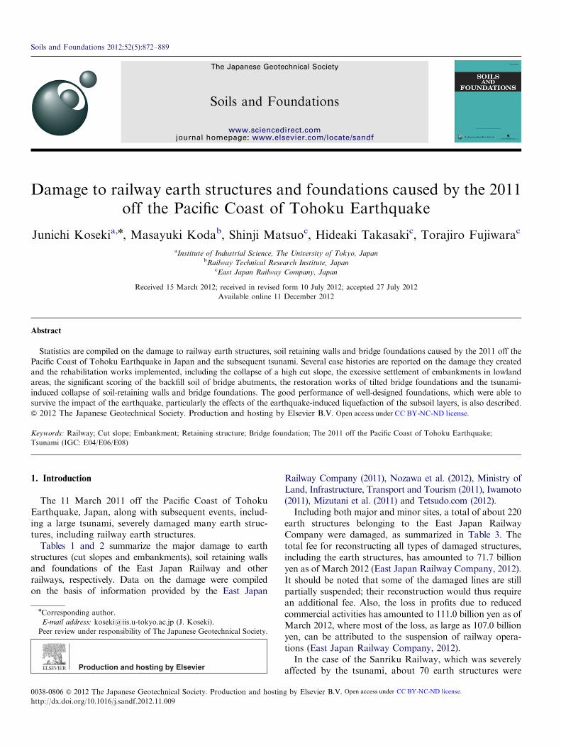
Fig. 2(a) shows the collapse of a cut slope (V:H¼1:1)along the JR Tohoku Line, located at 179kl00m betweenToyohara and Shirasaka Stations. It had a maximumheight of about 23 m, and consisted of volcanic ash-origin soil called loam. Several boring surveys, conductedafter the earthquake, have revealed that this soil layerexhibits typical SPT-N values of 2–4. As shown inFig. 2(b), the collapsed soil fully covered the railway track,while the masonry soil-retaining wall that had beenconstructed at the toe of the cut slope was found intact.In contrast, cut slopes in the adjacent areas consisting of
the same soil type, which had a maximum height of 14 m,were found to have survived the earthquake. The apparentcohesion of this type of soil, mobilized by the suction effectunder partially saturated conditions, may not have providedsufficient resistance against the earthquake load exerted on
ads and b) tsunami along the network of East Japan Railway.
(Road: collapsed)
Estimated failure plane
About 100
H-shaped steel piles(H = 0.3, L = 10.5, ctc.=2 m)
Reconstructed slope (V:H = 1: 1.5) with cast-in-place concrete lattice frame and shotcrete
(Existing soil retaining wall: undamaged)
After earthquake
Before earthquake(V:H = 1:1)
Abo
ut 2
3
Berm with concrete facing
(collapsed soil volume: about 13,000 m3)
Berm with concrete facing
Fig. 2. (a) and (b) Collapse of cut slope along JR Tohoku line at 179k100m between Toyohara and Shirasaka stations and (c) its reconstruction.
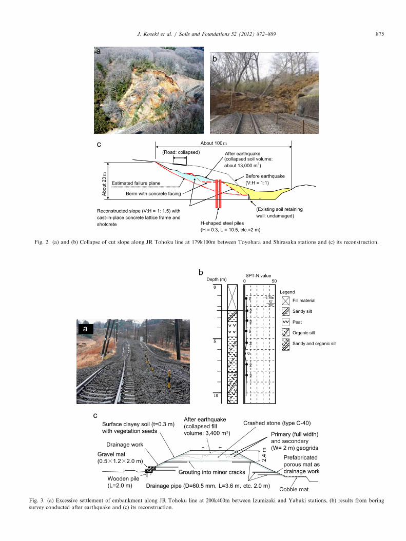
Fig. 3. (a) Excessive settlement of embankment along JR Tohoku line at 200k400m between Izumizaki and Yabuki stations, (b) results from boring
survey conducted after earthquake and (c) its reconstruction.
J. Koseki et al. / Soils and Foundations 52 (2012) 872–889 875

J. Koseki et al. / Soils and Foundations 52 (2012) 872–889876
the failed slope, while it may have been sufficient to supportthe other lower slopes.
As shown in Fig. 2(c), the failed slope was reconstructedinto a more gentle slope (V:H¼1:1.5), which was coveredwith a cast-in-place concrete lattice frame and shotcrete.H-shaped steel piles were imbedded to increase the resis-tance to sliding failures.
2.2. Damage to embankments
Fig. 3(a) shows the excessive settlements of an embank-ment along the JR Tohoku Line, located at 200k400mbetween Izumizaki and Yabuki Stations. It had a height ofabout 5 m and consisted of alternative layers of sandy soiland clayey soil. It was filled on soft subsoil layers (withtypical SPT-N values of 1 to 2) consisting of peat andorganic silt in a lowland area.
As shown in Fig. 3(b), a boring survey, conducted afterthe earthquake, has revealed that the groundwater level waslocated within the filled soil layer above the subsoil layers,suggesting that the saturated part of the fill, consisting of asandy soil, may have liquefied and induced a large deforma-tion. The survey has also revealed that the subsoil layers
4805 2750 2750
5600
Ballastrack
1563
580
400
1060
4805 2750 2750
5600
Ballastrack
Steel sheet pile (type III,
1563
580
400
1060
Tie rod (D=43.3 mmctc. 4.0m)
Fig. 4. (a) Excessive settlement of embankment along JR Narita line at 25k
consisted predominantly of organic soils, exhibiting SPT-Nvalues equal to or less than 2.As shown in Fig. 3(c), the failed embankment was
reconstructed into a reinforced embankment having thesame dimensions as the one before the failure, with a slopeof V:H¼1:1.6 to 1:2.2. For the fill material, a gravelly soilconsisting of crushed sand and/or volcanic stone particleswas used, which was well compacted and reinforced bygeogrids inserted at a vertical spacing of 30 cm. Full-widthgeogrids are used as primary reinforcements, while shorterand weaker geogrids with a width of 2 m are used assecondary reinforcements. The drainage capacity was alsoenhanced by using horizontal drainage pipes in the fill andgravel mats at the toe of the fill.Fig. 4(a) shows the excessive settlement of an embank-
ment along the JR Narita Line, which was located at25k500m between Aziki and Kobayashi Stations. It had aheight of about 3 m and was filled on sandy subsoil layersin a lowland area. After the earthquake, sand boiling fromthe subsoil level was observed at the level ground adjacentto the embankment. Therefore, the occurrence of liquefac-tion in the subsoil would have been the major cause of theexcessive settlement of the embankment.
Unit in mm
4535
5600
6040 75
00
t
3023
at V: H = 1
Pond
Unit in mm
4535
5600
6040 75
00
ted
L=7500)
3023
at V: H = 1 :1.5
Pond
Additional fill usingborrowed sandy soil (A=1.04 m2)
500m between Aziki and Kobayashi stations and (b) its reconstruction.
J. Koseki et al. / Soils and Foundations 52 (2012) 872–889 877
As shown in Fig. 4(b), the failed embankment wasreconstructed into an unreinforced embankment, havingdimensions which are similar to those before the failure, witha slope of V:H¼1:1.5. A pair of steel sheet piles, connected toeach other at the top with a tie rod, was imbedded at the toeof the embankment. This measure is expected to prevent thepossible deformation of the subsoil layers which may againliquefy during future earthquake-related events.
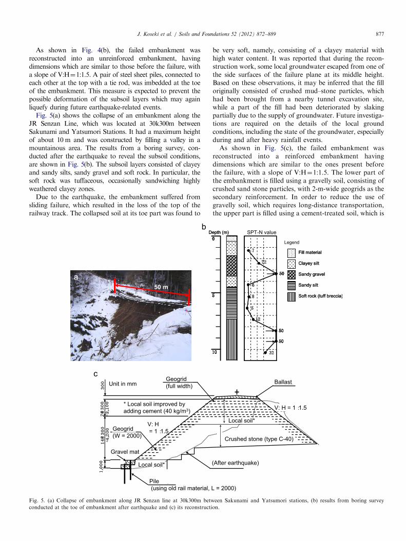
Fig. 5(a) shows the collapse of an embankment along theJR Senzan Line, which was located at 30k300m betweenSakunami and Yatsumori Stations. It had a maximum heightof about 10 m and was constructed by filling a valley in amountainous area. The results from a boring survey, con-ducted after the earthquake to reveal the subsoil conditions,are shown in Fig. 5(b). The subsoil layers consisted of clayeyand sandy silts, sandy gravel and soft rock. In particular, thesoft rock was tuffaceous, occasionally sandwiching highlyweathered clayey zones.
Due to the earthquake, the embankment suffered fromsliding failure, which resulted in the loss of the top of therailway track. The collapsed soil at its toe part was found to
50 m
Fig. 5. (a) Collapse of embankment along JR Senzan line at 30k300m betw
conducted at the toe of embankment after earthquake and (c) its reconstructi
be very soft, namely, consisting of a clayey material withhigh water content. It was reported that during the recon-struction work, some local groundwater escaped from one ofthe side surfaces of the failure plane at its middle height.Based on these observations, it may be inferred that the filloriginally consisted of crushed mud–stone particles, whichhad been brought from a nearby tunnel excavation site,while a part of the fill had been deteriorated by slakingpartially due to the supply of groundwater. Future investiga-tions are required on the details of the local groundconditions, including the state of the groundwater, especiallyduring and after heavy rainfall events.As shown in Fig. 5(c), the failed embankment was
reconstructed into a reinforced embankment havingdimensions which are similar to the ones present beforethe failure, with a slope of V:H¼1:1.5. The lower part ofthe embankment is filled using a gravelly soil, consisting ofcrushed sand stone particles, with 2-m-wide geogrids as thesecondary reinforcement. In order to reduce the use ofgravelly soil, which requires long-distance transportation,the upper part is filled using a cement-treated soil, which is
een Sakunami and Yatsumori stations, (b) results from boring survey
on.

Sea side
Fig. 6. Tsunami-induced damage to cut slope along JR Ofunato line at
89k900m between Wakinosawa and Otomo stations.
Sea side
Fig. 7. Tsunami-induced damage to embankment along North Rias line
of Sanriku Railway between Shimanokoshi and Tanohata stations
(adjacent to Hiraiga tunnel).
Fig. 8. Tsunami-induced damage to Orikasa station on embankment
along JR Yamada line.
J. Koseki et al. / Soils and Foundations 52 (2012) 872–889878
available nearby. The upper part is further combined withfull-width geogrids as the primary reinforcement. Thedrainage capacity was also enhanced by placing gravelmats at the toe of the fill on the downstream side of thevalley.
3. Tsunami-induced damage to cut slopes and embankments
Fig. 1(b) shows the locations of sites at which earthstructures were damaged by the tsunami along the EastJapan Railway network. Typical case histories are reportedherein, including damage to an embankment belonging tothe Sanriku Railway. The respective locations of these sitesare also indicated in the figure.
3.1. Damage to cut slopes
Fig. 6 shows the tsunami-induced damage to a cut slopealong the JR Ofunato Line, which was located at 89k900mbetween Wakinosawa and Otomo Stations. The slopesurface suffered from a shallow slide for a longitudinallength of about 100 m, among which shotcrete coveringhad been made for about 20 m.
When compared to the sites with embankments, thetsunami-induced damage to cut slopes was limited. Ingeneral, cut slopes are less affected by tsunamis becausethey are located at higher elevations than embankments.In addition, they appear to exhibit more resistance againsttsunami-induced erosion than embankments; this is possiblydue to the effect of natural cementation that has developedwithin the cut slopes.
3.2. Collapse of embankments
Fig. 7 shows the tsunami-induced damage to an embank-ment along the North Rias Line of the Sanriku Railway,which was located adjacent to the Hiraiga Tunnel betweenShimanokoshi and Tanohata Stations. The overflow of thetsunami caused severe erosion of the ballasted track and thefill body. Similar damage patterns were observed at manyother embankments, including railway stations constructedon embankments, as shown in Fig. 8.
Fig. 9(a) and (b) show the tsunami-induced damage to thebackfill soil of a bridge abutment along the JR YamadaLine, which was located adjacent to Namiita-kaigan Station.In addition to the washing away of the bridge girders, theoverflow of the tsunami caused severe scoring around theabutment body. As shown in Fig. 9(c), the top of the backfillsoil of the abutment and that of the bridge girders werelocated at a height of about 6 m above the ground level.
It should be noted that, in cases where the tsunami did notoverflow, there was no major induced damage to railwayembankments, as typically shown in Fig. 10(a). Consideringas well the good performance of highway embankments thatwere able to effectively block the tsunami, it is proposed thatrailway embankments be utilized as part of the multipledefense facilities against tsunamis (Miyagi Prefecture, 2011),
as schematically shown in Fig. 10(b). In doing so, it is alsoproposed that recent geotechnical technologies, such as rein-forced soil walls (Japanese Geotechnical Society, 2011 andRailway Technical Research Institute, 2011), be employed,as shown in Fig. 10(c).
4. Earthquake-induced damage to soil-retaining structures
and bridge foundations
Fig. 1(a) also shows the location of sites where soil-retaining structures and bridge foundations were damaged

Fig. 9. (a) and (b) Tsunami-induced damage to backfill soil of Namiita-gawa bridge abutment along JR Yamada line near Namiita-Kaigan station and
(c) original cross-section.
J. Koseki et al. / Soils and Foundations 52 (2012) 872–889 879
by earthquake motion along the East Japan Railwaynetwork. In general, the earthquake-induced damage tosoil-retaining walls and bridge foundations as railwaystructures was limited. Among them, some case historiesare reported herein, including damage to bridge founda-tions of the Tsukuba Express Line and no damage toviaducts of the JR East Keiyo Line located in ground thatunderwent liquefaction. The respective locations of thesesites are indicated in the figure.
4.1. Damage to soil-retaining structures
Fig. 11(a) shows the inclination and the breach of aretaining wall, consisting of plain concrete. It is located inthe face of a cut slope along the JR East TohokuShinkansen Line at 345k642m between Sendai and Fur-ukawa Stations (East Japan Railway Company, 2011).It has a length of 58 m and a maximum height of 9 m,including the embedment. Due to the earthquake, the wallinclination, measured at its base, changed from 70.71(which is the design gradient) to 741. This resulted in anopening of 100–150 mm at the top of the wall. The wallbody was breached at a height of about 1.0 m, forminga horizontal gap of about 150 mm at the constructionjoint, as shown in Fig. 11(b).
The above damage was possibly affected by the fact thatthe wall was relatively high, namely, about 7.4 m excludingthe embedment. It can be inferred that the earthquakeresponses of the wall and the cut slope may have beendifferent from each other, inducing an accumulation of the
opening at the wall top and the breach of the wall body,which was accompanied by the formation of several cracksin the original ground behind the wall, as shown inFig. 11(a).In the restoration work, a part of the wall was removed,
and the slope was cut with a gentle gradient and blown byshotcrete for surface protection, as shown in Fig. 11(c)and (d).Fig. 12(a) shows a damaged retaining wall, which is
located at the Shichigobori Bridge abutment along theJR East Tohoku Kamotsu Line at 350k047m betweenNagamachi and Sendai Cargo Terminal Stations (EastJapan Railway Company, 2011). A water channel existedin front of the wall, which had a height of 5.3 m from thebase of the channel, as shown in Fig. 12(b). Both the walland a part of the backfill soil collapsed due to theearthquake motion. The backfill consisted of sandy soilwith gravel. The collapsed retaining wall was built with thebridge, and was one of four retaining walls on which noprevious deformation had been recorded.According to the records, there were some deformations
and slides in the embankments around the bridge after theMiyagi-Ken-Oki Earthquake in 1978. Some drainage pipes(length of 3600 mm, outside diameter of 60.5 mm and intervalspacing of 1000 mm) had been inserted into the embankmentslope as countermeasures to increase both the drainagecapacity and the shear strength of the embankments.The above countermeasures seem to have acted effectively
in reducing the extent of the damage to the embankments,which settled moderately by about 100 mm. On the other

FarmlandRailway
Road
Green belt
Coastal dike
Residential areas
Sea
FarmlandResidential areas
RailwayRoad
Green belt
Coastal dike
Nailed slope withgood drainage Original ground
surface Geosynthetic- reinforced soilstructures with rigid facing
Fig. 10. (a) Embankment along JR Joban line between Hisanohama and Suetsugi stations that blocked the tsunami; and schematic diagrams of multiple
tsunami defense facilities showing applications of (b) conventional and (c) recent geotechnical technologies to the restoration program (after Japanese
Geotechnical Society, 2011).
J. Koseki et al. / Soils and Foundations 52 (2012) 872–889880
hand, the wall and its backfill, beside the abutment, had beenwithout any countermeasures, and thus, completely collapsed.
As shown in Fig. 12(c)–(e), during the restoration work,a geogrid-reinforced soil-retaining wall was used, whichformed a part of the water channel revetment as well. Thecollapsed soil, from which grass and trees were removed,was reused as the backfill material. During the backfillingwork, the water content of the backfill soil was controlledto exceed 95% of its optimum value. The compactiondegrees of the backfill were measured as well; theyexhibited minimum and mean values of 91.9% and92.1%, respectively.
4.2. Damage to bridge foundations
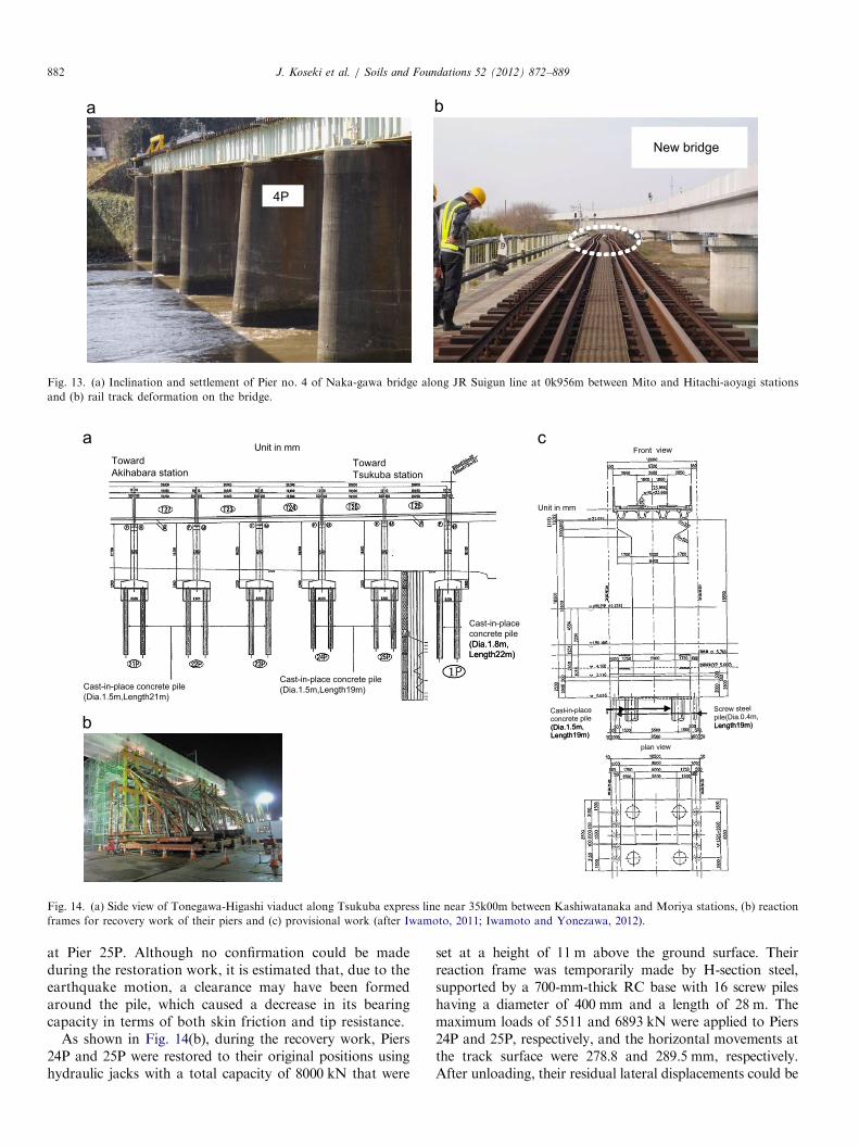
Fig. 13(a) shows the inclination and the settlement ofPier 4P, located at the Naka-gawa Bridge on the JR EastSuigun Line at 0k956m between Mito and Hitachi-AoyagiStations. This pier was supported by a wooden pilefoundation resting on subsoil layers consisting of 11.15-m-thick silt to fine sand layers with SPT-N values in the
range of 2–8, with an exceptional value of 32 measured at adepth of about 8.3 m, and a 2.4-m-thick gravelly layer withSPT-N values exceeding 50. They were underlain by a stiffmud–stone layer.Due to the earthquake, the foundation moved 200 mm
horizontally and settled 50 mm down at the top of the pier(East Japan Railway Company, 2011). As shown in Fig. 13(b),track deformation occurred with the pier displacement.The bridge was restored by switching from the old
bridge to a new bridge (Fig. 13(b)). It was reconstructedas part of the river improvement works.Fig. 14(a) shows a side view of the Tonegawa-higashi
Viaduct near 35k000m between Kashiwatanaka and MoriyaStations on the Tsukuba Express Line. The movement atthe track surface was a maximum of 151 mm on the top ofPiers 24P and 25P (Iwamoto, 2011; Iwamoto and Yonezawa,2012).The Tonegawa-higashi Viaduct is located at the Inatoi
Balancing Reservoir of the Tone River Basin in MoriyaCity, Ibaraki Prefecture, and it has a continuous beamwith a respective length of 20 m. Each pier is supported by

JR propertyPrivate property
After earthquake:74 deg.
Gap&breachCracksInclination
Assumed failure plane
Opening
Before earthquake:70.7 deg.
JR propertyPrivate property
After earthquake:74 deg.
Gap&breachCracksInclination
Assumed failure plane
Opening
JR propertyPrivate property
After earthquake:74 deg.
Gap&breachCracksInclination
Assumed failure plane
Opening
Before earthquake:70.7 deg.
5.0m
2.0m
1:1.52.0m
1:1.0
1:0.35
Removal of damagedretaining wall
New power poleSlope excavation
Downline
Upline
Reuse of undamaged retaining wall
Telecommunication cables
5.0m
Shotcrete2.0m
1:1.52.0m
Shotcrete 1:1.0
1:0.35
Removal of damagedretaining wall
New power poleSlope excavation
Downline
Upline
Reuse of undamaged retaining wall
Telecommunication cables
Fig. 11. (a) and (b) Inclination and breach of retaining wall along JR Tohoku Shinkansen line at 345k642m between Sendai and Furukawa stations
and (c) and (d) its restoration (after East Japan Railway Company, 2011).
8300
5650
60053
00
3000
1:0.
353000
2900
450
600
750
8300
8300
5650
60053
00
3000
1:0.
353000
2900
450
600
750 Unit i n mm
Geogrid
Concrete facing
1:0.35
Geogrid -reinforced retaining wall
Collapsed slope
Geogrid
Fig. 12. (a) Collapse of retaining wall beside abutment of Shichigobori Bridge along JR Tohoku Kamotsu line at 350k047m between Nagamachi and Sendai
cargo terminal stations, (b) its side view and (c), (d) and (e) its reconstruction by using geogrid-reinforced soil (after East Japan Railway Company, 2011).
J. Koseki et al. / Soils and Foundations 52 (2012) 872–889 881
four cast-in-place RC piles with a diameter of 1.5–1.8 mand a length of 19–22 m. The track is a straight line at aninclination of 1.4% towards Tsukuba Station. As listed in
Table 5, a settlement of 80 mm and a lateral displacementof 132 mm occurred at the track surface at Pier 24P, and asettlement of 50 mm and a lateral displacement of 151 mm
4P
New bridge
Fig. 13. (a) Inclination and settlement of Pier no. 4 of Naka-gawa bridge along JR Suigun line at 0k956m between Mito and Hitachi-aoyagi stations
and (b) rail track deformation on the bridge.
Toward Akihabara station
Toward Tsukuba station
Cast-in-place concrete pile (Dia.1.5m,Length21m)
Cast-in-place concrete pile (Dia.1.5m,Length19m)
Cast-in-place concrete pile (Dia.1.8m,Length22m)
Side viewToward Akihabara station
Toward Tsukuba station
Cast-in-place concrete pile (Dia.1.5m,Length21m)
Cast-in-place concrete pile (Dia.1.5m,Length19m)
Cast-in-place concrete pile (Dia.1.8m,Length22m)
Side viewUnit in mm
Screw steel pile(Dia.0.4m,Length19m)
Front view
Cast-in-place concrete pile (Dia.1.5m,Length19m)
plan view
Screw steel pile(Dia.0.4m,Length19m)
Front view
Cast-in-place concrete pile (Dia.1.5m,Length19m)
plan view
Unit in mm
Fig. 14. (a) Side view of Tonegawa-Higashi viaduct along Tsukuba express line near 35k00m between Kashiwatanaka and Moriya stations, (b) reaction
frames for recovery work of their piers and (c) provisional work (after Iwamoto, 2011; Iwamoto and Yonezawa, 2012).
J. Koseki et al. / Soils and Foundations 52 (2012) 872–889882
at Pier 25P. Although no confirmation could be madeduring the restoration work, it is estimated that, due to theearthquake motion, a clearance may have been formedaround the pile, which caused a decrease in its bearingcapacity in terms of both skin friction and tip resistance.
As shown in Fig. 14(b), during the recovery work, Piers24P and 25P were restored to their original positions usinghydraulic jacks with a total capacity of 8000 kN that were
set at a height of 11 m above the ground surface. Theirreaction frame was temporarily made by H-section steel,supported by a 700-mm-thick RC base with 16 screw pileshaving a diameter of 400 mm and a length of 28 m. Themaximum loads of 5511 and 6893 kN were applied to Piers24P and 25P, respectively, and the horizontal movements atthe track surface were 278.8 and 289.5 mm, respectively.After unloading, their residual lateral displacements could be

Table 5
Residual lateral displacements and settlements of the Tonegawa-higashi
viaduct (modified after Iwamoto, 2011).
Pier no. Lateral disp.
on rail track (mm)
Settlement of
rail track (mm)
22P þ1 0
23P þ9 50
24P �132 80
25P �151 50
1P (located next to 25P) �17 0
Toward Kashimajingu station
Toward Nobukata station
Box girder
Box girder
Top of pier
Toward Kashimajingu station
Toward Nobukata station
Box girder
Box girder
Platform
Top of pier
J. Koseki et al. / Soils and Foundations 52 (2012) 872–889 883
reduced to 43 and 40 mm, respectively, which were withinthe adjustable ranges of the rail-fastening devices. In addi-tion, the settled beams were jacked up, and spacers wereinserted into the existing shoes.
To reinforce the foundation, 10 screw piles with adiameter of 400 mm and a length of 19 m were imbeddedbeside Piers 23P, 24P and 25P and connected to the footing,as shown in Fig. 14(c). In doing so, some of the screw pilesthat had been employed to support the temporary reactionframe, mentioned above, were reused.
28.0 m
Platform
1350mm800mm
700mm
600mm
28.0 m
Fig. 15. (a) and (b) Steel beam rotation of Daiichi-Kyuchu bridge along
JR Kashima line at 14kl71m between Nobukata and Kashimajingu stations.
4.3. Superstructure damage to skewed bridge
Fig. 15(a) shows the steel beam rotations of the Daiichi-Kyuchu Bridge on the JR East Kashima Line at 14k171mbetween Nobukata and Kashimajingu Stations. The bridgehas 28-m-span steel beams with box sections (i.e., boxgirders). The piers have a skew angle of 601with respect tothe track line. They were supported by a pile foundationusing pre-stressed concrete piles having a diameter of40 cm and a length of 20–31 m. Between their footingand the supporting firm soil layers, with SPT-N valuesexceeding 50, there were subsoil layers consisting of about3-m-thick fine sand layers with SPT-N values in the rangeof 4 to 15, about a 1-m-thick peat layer with an SPT-Nvalue of 2, an approximately 16-m-thick clayey silt layerexhibiting SPT-N values of zero (i.e., the hammer settleddown by its self-weight) and loose to medium-dense finesand layers between which a 0.5-m-thick peat layer wassandwiched.
As shown in Fig. 15(b), one beam rotated by about1350 mm at one side, with a fixed end, and by about800 mm at the other side, with a movable end (East JapanRailway Company, 2011). Similarly, the other beam rotatedby about 700 mm and 600 mm, respectively.
In general, the seismic response of the beams and thepiers with a skew angle is asymmetric with respect to thetrack line, inducing a rotational excitation on a horizontalplane. As a result, the beam may suffer residual rotation.This seems to be the case with the above skewed bridge.Similar behavior was reported for road bridges in the 1995Hyogo-ken Nanbu Earthquake.
During the restoration work, the beam was temporarily sup-ported by a hydraulic jack and restored to its original position.
Devices to limit earthquake-induced displacement wereinstalled at the top of the piers instead of side blocks.
4.4. No damage to bridge foundation in liquefied subsoil
As shown in Fig. 16, the JR Keiyo Line in the region ofUrayasu and Ichikawa Cities, Chiba Prefecture, includingShin-Urayasu Station, to be mentioned below, is con-structed in a low land area at the mouth of the Edo River,which is at an elevation of 2 to 3 m above the Tokyo Pile(Tokyo Office of Japan Railway Construction PublicCorporation, 1991). The ground consists of a landfill layer(B), Holocene sand layer (As), Holocene clay layer (Ac)and diluvium layers (Ds and Dc). The surface landfill layerconsists of fine silty sand and sandy silt, which are bothsoft and exhibit SPT-N values ranging from 0 to 3. TheHolocene sand layer consists of fine sand and fine siltysand, exhibiting SPT-N values of less than 10. It isestimated that the surface landfill layer and the Holocenesand layer were liquefied by the earthquake motion in thevicinity of Shin-Urayasu Station.

Ichikawa cityUrayasu city
Shinurayasu station
Maihama station
Ichikawashiohama station
12k720m16k060m
18k220m
T.P.(m)
0
-10
-20
-30
-40
-50
-60
-70
Viaduct of JR Keiyo line
Ichikawa cityUrayasu city
Shinurayasu station
Maihama station
Ichikawashiohama station
12k720m16k060m
18k220m
Ichikawa cityUrayasu city
Shinurayasu station
Maihama station
Ichikawashiohama station
12k720m16k060m
18k220m
T.P.(m)
0
Viaduct of JR Keiyo line
Fig. 16. Ground profile along JR Keiyo line (Tokyo Office of Japan Railway Construction Public Corporation, 1991).
J. Koseki et al. / Soils and Foundations 52 (2012) 872–889884
Fig. 17(a) shows side and front views of the Daini-Irifune(rigid frame) Viaducts near Shin-Urayasu Station at 16k060mon the JR Keiyo Line (Tokyo Office of Japan RailwayConstruction Public Corporation, 1991). They are stationviaducts supported by end-bearing pile foundations, whichconsist of steel tube concrete piles (SC piles) for the upperpiles and pre-stressed high-strength concrete piles (PHC piles)for the lower piles. Considering the possible occurrence ofliquefaction, they had been designed without considering thesubgrade reaction of the soil layers from the surface to adepth of 10 m. Due to the earthquake, liquefaction did takeplace, inducing a residual ground surface settlement of 100–300 mm around these viaducts, while they did not suffer anystructural damage, as shown in Fig. 17(b) and (c).
Fig. 18(a) shows side and front views of the Daini-Urayasu(beam type) Viaducts at 13k899m on the JR Keiyo Line(Tokyo Office of Japan Railway Construction PublicCorporation, 1991). Except for the station viaducts men-tioned above, the viaducts of the JR Keiyo Line in betweenShinkiba and Ichikawa-Shiohama Stations are supported bypile foundations using long friction piles. They had beendesigned considering the effects of negative friction, causedby residual settlement, which would occur after the comple-tion of the construction work. In addition, they had beendesigned without considering the skin friction to be mobilizedin the uppermost layers from the surface to a depth of 10 mby assuming the possible occurrence of liquefaction. Due tothe earthquake, liquefaction-induced ground surface settle-ment of 100 to 300 mm took place around the viaducts, while
they did not suffer any structural damage, as shown inFig. 18(b) and (c).
5. Tsunami-induced damage to soil-retaining structures
and bridge foundations
Fig. 1(b) shows the locations of sites at which retainingstructures and bridge foundations were damaged by thetsunami along the East Japan Railway network. Typicalcase histories are reported herein. Their respective locationsare also indicated in Fig. 1(b).
5.1. Collapse of soil-retaining structure
Fig. 19(a)–(c) show the tsunami-induced damage to theretaining wall beside the Ohsawa-gawa Bridge along theJR Kesennuma Line at 54k098m between Motoyoshi andKoganezawa Stations (East Japan Railway Company,2011). The wall fell down to the seaside, and the backfillsoil was eroded by the tsunami.The Ohsawa-gawa Bridge had a total length of 53.2 m,
consisting of 4 T-type reinforced concrete beams, 3 piersand 2 abutments. Due to the tsunami, these beams andpiers fell down into the river.
5.2. Damage to bridge foundations
Fig. 20(a) and (b) show the tsunami-induced damage tothe Ohtsuchi-kawa Bridge along the JR Yamada Line at
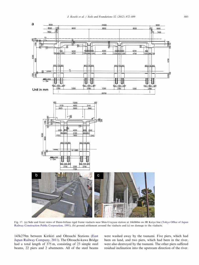
Fig. 17. (a) Side and front views of Daini-Irifune rigid frame viaducts near Shin-Urayasu station at 16k060m on JR Keiyo line (Tokyo Office of Japan
Railway Construction Public Corporation, 1991), (b) ground settlement around the viaducts and (c) no damage to the viaducts.
J. Koseki et al. / Soils and Foundations 52 (2012) 872–889 885
143k279m between Kirikiri and Ohtsuchi Stations (EastJapan Railway Company, 2011). The Ohtsuchi-kawa Bridgehad a total length of 375 m, consisting of 23 simple steelbeams, 22 piers and 2 abutments. All of the steel beams
were washed away by the tsunami. Five piers, which hadbeen on land, and two piers, which had been in the river,were also destroyed by the tsunami. The other piers sufferedresidual inclination into the upstream direction of the river.

SC pile(Pile Dia. 600mm)
SC pile(Pile Dia. 600mm)
Unit in mm
Fig. 18. (a) Side and front views of Daini-Urayasu beam type viaducts at 13k899m on JR Keiyo line (Tokyo Office of Japan Railway Construction Public
Corporation, 1991), (b) ground settlement around the viaducts and (c) no damage to the viaducts.
J. Koseki et al. / Soils and Foundations 52 (2012) 872–889886
Fig. 21(a) and (b) show the tsunami-induced damage tothe Tsuya-gawa Bridge along the JR Kesennuma Lineat 50k099m between Rikuzenkoizumi and MotoyoshiStations (East Japan Railway Company, 2011). TheTsuya-gawa Bridge is 462 m long in total, consisting of 6pre-stressed concrete beams (PC beams) and 13 reinforcedconcrete simple beams (RC beams), 17 piers and 2abutments. All the PC beams, having a length of 35 or40 m, were severely cracked and washed away by thetsunami. In addition, four piers fell down due to thetsunami. Each of the piers had been reinforced by 48 steelbars with a nominal diameter of 29 mm, while some steelbars were torn down by the tsunami. The backfill soil ofone of the abutments was washed away by the tsunami aswell. Fig. 21(c) shows the foundation scouring of a pier ina river bed, where the maximum depth of scouring wasabout 1 m.
6. Summary
In addition to compiling the statistics on the damage torailway earth structures, soil retaining walls and bridgefoundations, some case histories on their performancehave been described.
Case histories on the earthquake-induced damage torailway earth structures, including cut slopes and embank-ments, can be summarized as follows:
(1)
A cut slope, with a height of about 30 m and consistingof a volcanic ash-origin soil called loam, collapsed. Onthe other hand, cut slopes in adjacent areas, consistingof the same type of soil and with a maximum height of14 m, survived the earthquake.(2)
Embankments that had been filled on soft or liquefi-able subsoil layers in lowland areas suffered fromexcessive settlement. In one case, with a soft subsoillayer, the groundwater level was found within the filledsoil layer above the subsoil, suggesting that the satu-rated part of the fill consisting of a sandy soil may haveliquefied and induced significant deformation. Inanother case with a liquefiable subsoil layer, sandboiling from the subsoil layer was observed, confirmingthe occurrence of liquefaction in the subsoil.(3)
An embankment that had been filled on a valley in amountainous area suffered from sliding failure. Thecollapsed soil at its toe part was found to be very soft,namely, consisting of a clayey soil with high watercontent.
Location of damaged retaining wall
Fig. 19. (a), (b) and (c) Tsunami-induced damage to retaining wall beside Ohsawa-gawa bridge along JR Kesennuma line at 54k098m between Motoyoshi
and Koganezawa stations.
Fig. 20. (a) and (b) Tsunami-induced damage to Ohtsuchi-kawa bridge on JR East Yamada line at 143k279m between Kirikiri and Ohtsuchi stations.
J. Koseki et al. / Soils and Foundations 52 (2012) 872–889 887
The tsunami-induced damage to railway earth structurescan be summarized as follows:
(1)
Embankments that were subjected to the tsunamioverflow suffered from erosion of the ballasted trackon the top and the fill body itself. In particular, therewas significant scoring at the backfill soil of bridgeabutments. Railway stations constructed on embank-ments were also severely damaged.(2)
Without overflow, the tsunami induced no majordamage to embankments in general. Considering therelatively good performance of the highway andrailway embankments that were able to effectivelyblock the tsunami, it is proposed that they shallbe utilized as part of the multiple defense facilitiesagainst tsunamis, while employing recent geotechni-cal technologies, such as reinforced soil-retainingwalls.
Fig. 21. (a), (b) and (c) Tsunami-induced damage to Tsuya-gawa bridge on JR East Kesennuma line at 50k099m between Rikuzenkoizumi and
Motoyoshi stations.
J. Koseki et al. / Soils and Foundations 52 (2012) 872–889888
The performance of the soil-retaining walls and the
bridge foundations of railway facilities against earthquakeloads can be summarized as follows:(1)
Damage to soil-retaining walls induced by earthquakemotion was generally limited, while the inclination of aretaining wall on a cut slope and the collapse of aretaining wall at the side of a bridge abutment wereobserved. In both cases, the earthquake-response char-acteristics of the walls and their backfill soil may havebeen largely different from each other, affecting theirpoor performance.(2)
Earthquake-induced damage to bridge foundationswas also limited. However, it was learned from thecase history on the Tonegawa-higashi Viaduct that,once they were damaged, particularly when they under-went tilting, their restoration work required a signifi-cant amount of time and effort. A beam and piers,which had a skew angle against the track line, sufferedfrom residual rotation, possibly due to the torsionbehavior during the earthquake. Detailed attentionshould be given to such types of structures.(3)
Two types of viaducts, that had been designed con-sidering the effects of liquefaction and constructed onreclaimed land, suffered no structural damage, despitethe residual settlement of the surrounding ground by100–300 mm due to liquefaction.The performance of the soil-retaining walls and thebridge foundations of railway facilities during the tsunamican be summarized as follows:
(1)
Soil-retaining walls, subjected to the overflowing of thetsunami, collapsed completely, and their backfill soilswere washed away. They had not been designed to resistthe effects of tsunamis. Even at the present time, it wouldbe difficult to establish rational design procedures forthem considering the effects of tsunamis. Use of aretaining wall structure that would perform in a ductilemanner against the overflow of tsunamis, such asreinforced soil-retaining walls, is desirable.(2)
Bridge foundations in rivers and in dry river bedscollapsed completely by the tsunami; they had not been
J. Koseki et al. / Soils and Foundations 52 (2012) 872–889 889
designed to combat the effects of tsunamis. When thetsunami overflowed them, their beams, piers and abut-ments were washed away. It is important to reduce theforce of tsunamis acting on the beams and foundations,for example, by adopting thin beams, particularly whenconnecting the beam and pier rigidly.
Acknowledgments
The authors wish to express their sincere thanks toProfessor K. Okada of Kokushikan University, Dr. M.Tateyama, Mr. M. Samizo and Dr. K. Watanabe of theRailway Technical Research Institute and Mr. S. Shimizu andMr. N. Masuda of Tekken Corporation for their valuablecomments on the case studies which were reported in thispaper. The kind assistance of those who are in charge of therehabilitation works of the railway earth structures and thosewho conducted the damage surveys is also highly appreciated.
References
East Japan Railway Company, 2011. Special issue on the 2011 off the
Pacific coast of Tohoku earthquake and railway structures, Structural
Engineering Data, 37, 302p (in Japanese).
East Japan Railway Company, 2012. Accounting report as of March 2012
(in Japanese). Available from: /http://www.jreast.co.jp/investor/
guide/pdf/201203guide1.pdfS (accessed 05.07.12).
Iwamoto, H., 2011. Recovering work on Tonegawa-higashi viaduct of
Tsukuba Express. Journal of Japan Railway Civil Engineering
Association 49 (10), 52–54 (in Japanese).
Iwamoto, H., Yonezawa, T., 2012. Damage to Tonegawa-higashi viaduct
of Tsukuba Express and its recovering work. Kisoko 40 (4),
74–77 (in Japanese).
Japanese Geotechnical Society, 2011. Geo-hazards during earthquakes
and mitigation measures-lessons and recommendations from the 2011
Great East Japan Earthquake, 84p.
Miyagi Prefecture, 2011. Miyagi prefecture disaster recovery plan. Avail-
able from: /http://www.pref.miyagi.jp/seisaku/sinsaihukkou/keikaku/
index en.htmS (accessed 16.03.12).
Ministry of Land, Infrastructure, Transport and Tourism, 2011. Report
of survey and restoration planning of tsunami-induced damage to
medium- and small-scale private railways (in Japanese).
Mizutani, K., Suzuki, Y., Okada, N., 2011. Damage to Keisei Electric
Railway and its restoration. Journal of Japan Railway Civil Engineering
Association 49 (10), 48–51 (in Japanese).
Mochizuki, M., 2011. Damage to Sanriku Railway and its restoration
activities up to today. Journal of Japan Railway Civil Engineering
Association 49 (10), 43–45 (in Japanese).
Nozawa, S., Shirasaki, H., Wada, A., Tomori, M., 2012. Damage and
restoration of the railway structures caused by the 2011 off the Pacific
coast of Tohoku earthquake. Japanese Geotechnical Journal, Japanese
Geotechnical Society 7 (1), 127–137 (in Japanese).
Railway Technical Research Institute, 2011. Technical proposals for
restoration and rehabilitation works of earthquake-induced damage
to railways, 94p (in Japanese).
Tetsudo.com, 2012. Summary of re-opening status of suspended railway
lines (in Japanese). Available from: /http://www.tetsudo.com/special/
disaster2011/?date=20120317S (accessed 05.07.12).
Tokyo Office of Japan Railway Construction Public Corporation, 1991.
Keiyo line construction record, pp. 167–168 (in Japanese).