Modelling and Analysis of High-damping Rubber Bearings for ...
DAMAGE OF RUBBER BEARINGS AND DAMBERS OF BRIDGES
IN 2011 GREAT EAST JAPAN EARTHQUAKE
Yoshikazu TAKAHASHI1
1 Associate Professor, Disaster Prevention Research Institute, Kyoto University, Kyoto, Japan, [email protected]
ABSTRACT: In the 2011 Great East Japan Earthquake, many structures were heavily damaged by Tsunami, but most structures designd by post-1990 code were not damaged by ground motion. However in some bridges designed by post-1995 code, rubber bearings and dampers were severely damaged. In this earthquake, cracks of rubber bearings were observed in the wide region in the east part of Japan, and in Sendai area the rupture of bearings were occurred in two highway viaducts. The paper summarizes damage of rubber bearings and dampers of bridges. Key Words: Rubber bearing, Damper, Bridges, Great East Japan earthquake
INTRODUCTION The 2011 off the Pacific coast of Tohoku Earthquake with moment magnitude of 9.0 occurred at 14:46 (local time in Japan) on March 11, 2011 along the Japan Trough in the Pacific. It was the sixth largest earthquake ever recorded in the world. The fault zone extended 450 km and 200 km in the north-south and west-east directions, respectively. Extensive damage occurred in the wide region in the east part of Japan.
The author surveyed Miyagi Pref. and Iwate Pref. between March 13-16 to collect damage of bridges induced by the ground motion, and was dispatched by Japan Society of Civil Engineers for field damage investigation to bridges between March 29-April 3, 2011. In addition to these investigations, damage investigations ,including Ibaragi Pref. and Kanagawa Pref., were conducted several times. This paper presents damage of rubber bearings and dampers of bridges.
GROUND MOTION RECORDED AROUND BRIDGES A number of strong motion accelerations were recorded by Japan Meteorological Agency (JMA), the National Institute of Earth Science and Disaster Prevention (NIED), Ministry of Land, Infrastructure, Transport and Tourism (MLIT). And NEXCO also has a network of seismometer for traffic control. Rank 7 of JMA seismic intencity is recorded at Tsukidate, Miyagi-Pref. The ground motion continued over 300 seconds, and the peak ground acceleration of 2765 gal was recorded.
Proceedings of the International Symposium on Engineering Lessons Learned from the 2011 Great East Japan Earthquake, March 1-4, 2012, Tokyo, Japan
1333

Fig. 1 Location of bridges shown in this article (red star) on aftershock distribution map
Fig. 2 Location of bridges and seismograph station
1334

(a) Sendai Area
(b) Hitachi Area
(c) Mito Area
Fig. 3 Response Spectra with JRA Design Spectra (L2-Type II)
Fig. 2 shows the distribution of seismograph stations around the bridges and the response spectra
are shown in Fig. 3. In Sendai area, K-net Sendai and NEXCO Sendai Higashi are similar to the Design Spectra of Level II – Type II (Soil Type I), but the other ground motion are smaller than the Design Spectra especially in 0.5-5 second.
JRA SEISMIC DESIGN SPECIFICATIONS REVISED AFTER 1995 The Kobe Earthquake (Hyogo-ken Nanbu Earthquake) of January 17, 1995, caused destructive damage to highway bridges, including collapse of superstructures, occurred at 25 sites. Based on the lessons learned from the earthquake, the Japan Road Association’s (JRA) Specifications for Highway
10
100
1000
10000
0.1 1 5
Sa (g
al) [
h=0.
05]
Period (sec)
NS dir.
K-net SendaiNEXCO SendaiHigashiNEXCO SendaiPortKitaNEXCO RifuShiogamaNEXCO ShirakashiDai
10
100
1000
10000
0.1 1 5
Sa (g
al) [
h=0.
05]
Period (sec)
EW dir.
K-net SendaiNEXCO SendaiHigashiNEXCO SendaiPortKitaNEXCO RifuShiogamaNEXCO ShirakashiDai
10
100
1000
10000
0.1 1 5
Sa (g
al) [
h=0.
05]
Period (sec)
NS dir.
K-net HitachiMLIT Hitachi
NEXCO Hitachi Kita
10
100
1000
10000
0.1 1 5
Sa (g
al) [
h=0.
05]
Period (sec)
EW dir.
K-net HitachiMLIT Hitachi
NEXCO Hitachi Kita
10
100
1000
10000
0.1 1 5
Sa (g
al) [
h=0.
05]
Period (sec)
NS dir.
K-net NakaMinatoNEXCO MitoMinami
10
100
1000
10000
0.1 1 5
Sa (g
al) [
h=0.
05]
Period (sec)
EW dir.
K-net NakaMinatoNEXCO MitoMinami
1335
Bridges, Part V: Seismic Design were significantly revised in 1996. The intensive earthquake motion with a short distance from the inland earthquakes with Magnitude 7 class has been considered in the design. As the design philosophy for large earthquakes, the JRA code does not allow critical damage for standard bridges and allow limited damage for important bridges. The 1990 JRA code required that RC piers be designed by ductility design method, but the 1996 JRA code expanded the scope of applicability of the ductility design method to include not only RC piers but steel piers and other structural elements that are seriously affected by earthquake such as foundations, unseating prevention systems and bearings.
SUMMARY OF URGENT SAFETY INSPECTIONS OF BRIDGES After March 11, 2011, MLIT conducted urgent safety inspections of 1,504 bridges of 11 National Route in Iwate, Miyagi and Fukushima Prefectures in which strong seismic intensity of stronger than rank of 6 lower was recorded. 1,350 bridges were located in area of seismic intensity of stronger than the rank of 5 upper and 815 bridges were suffered damage (Maeda et al. 2011). In this earthquake, no bridges were severely damages induced by ground motions but 140 bridges were affected by Tsunami and girders of 5 bridges on Route 45 were washed away by Tsunami.
The major damage of bridges is subsidence of backfill soil of abutments (364 bridges) and bearings (80 bridges) and expansion joints (67 bridges). The main failures of bearings were excessive movement and breakage of side block of steel bearings.
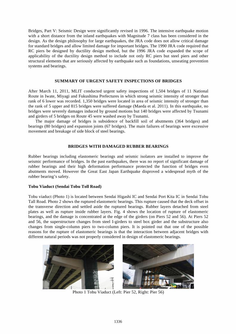
BRIDGES WITH DAMAGED RUBBER BEARINGS Rubber bearings including elastomeric bearings and seismic isolators are installed to improve the seismic performance of bridges. In the past earthquakes, there was no report of significant damage of rubber bearings and their high deformation performance protected the function of bridges even abutments moved. However the Great East Japan Earthquake disproved a widespread myth of the rubber bearing’s safety. Tobu Viaduct (Sendai Tobu Toll Road) Tobu viaduct (Photo 1) is located between Sendai Higashi IC and Sendai Port Kita IC in Sendai Tobu Tall Road. Photo 2 shows the ruptured elastomeric bearings. This rupture caused that the deck offset in the transverse direction and settled aside the ruptured bearings. Rubber layers detached from steel plates as well as rupture inside rubber layers. Fig. 4 shows the location of rupture of elastomeric bearings, and the damage is concentrated at the edge of the girders (on Piers 52 and 56). At Piers 52 and 56, the superstructure changes from steel I-girders to steel box girder and the substructure also changes from single-column piers to two-column piers. It is pointed out that one of the possible reasons for the rupture of elastomeric bearings is that the interaction between adjacent bridges with different natural periods was not properly considered in design of elastomeric bearings.
Photo 1 Tobu Viaduct (Left: Pier 52, Right: Pier 56)
1336
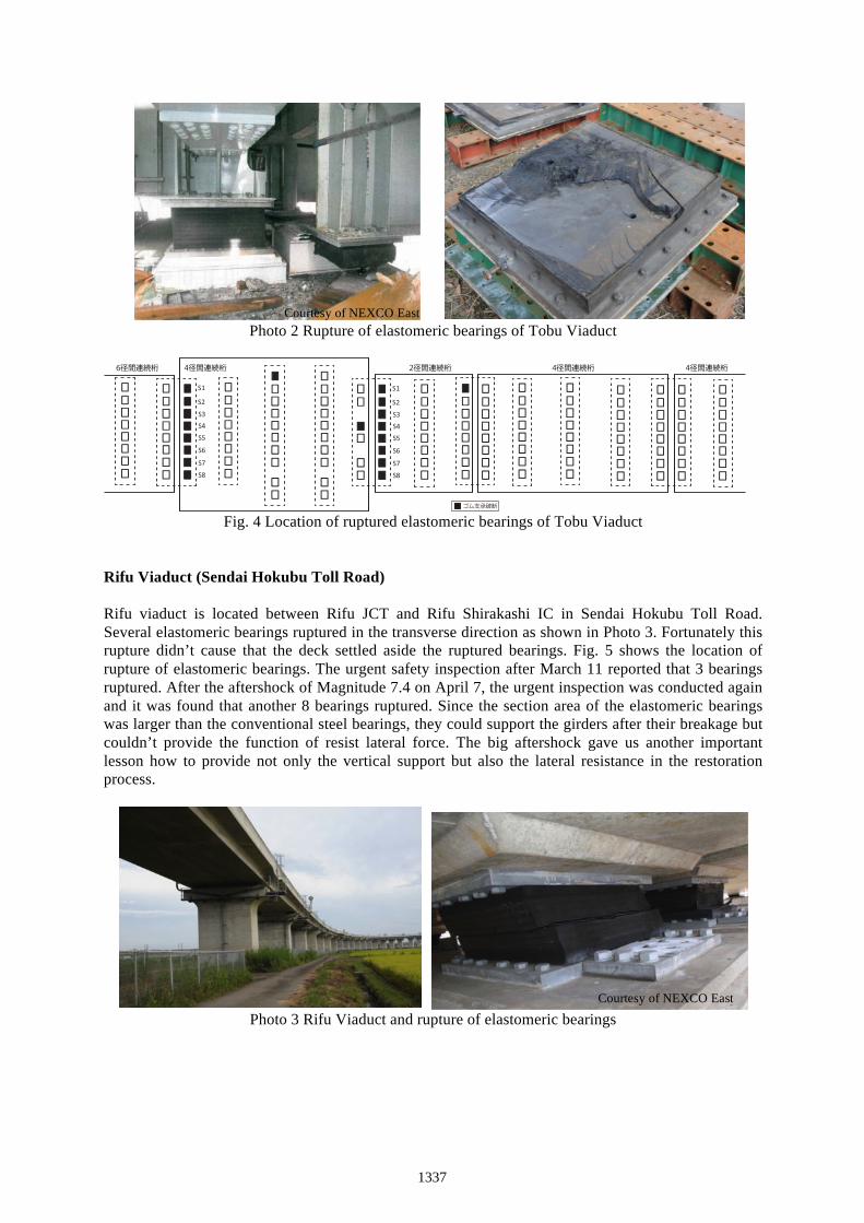
Photo 2 Rupture of elastomeric bearings of Tobu Viaduct
Fig. 4 Location of ruptured elastomeric bearings of Tobu Viaduct
Rifu Viaduct (Sendai Hokubu Toll Road) Rifu viaduct is located between Rifu JCT and Rifu Shirakashi IC in Sendai Hokubu Toll Road. Several elastomeric bearings ruptured in the transverse direction as shown in Photo 3. Fortunately this rupture didn’t cause that the deck settled aside the ruptured bearings. Fig. 5 shows the location of rupture of elastomeric bearings. The urgent safety inspection after March 11 reported that 3 bearings ruptured. After the aftershock of Magnitude 7.4 on April 7, the urgent inspection was conducted again and it was found that another 8 bearings ruptured. Since the section area of the elastomeric bearings was larger than the conventional steel bearings, they could support the girders after their breakage but couldn’t provide the function of resist lateral force. The big aftershock gave us another important lesson how to provide not only the vertical support but also the lateral resistance in the restoration process.
Photo 3 Rifu Viaduct and rupture of elastomeric bearings
S1
S2S3S4S5S6
S7S8
6径間連続桁 4径間連続桁 4径間連続桁2径間連続桁 4径間連続桁
S1
S2S3S4S5S6
S7S8
ゴム支承破断
Courtesy of NEXCO East
Courtesy of NEXCO East
1337

Photo 4 Various crack patterns of damaged elastomeric bearings of Rifu Viaduct
Fig. 5 Rupture of elastomeric bearings of Rifu Viaduct
Shin Nakagawa Bridge (Higashi Mito Toll Road) Shin Nakagawa Bridge (Fig. 6) is the cable-stayed bridge located at Mito City in Ibaragi Prefecture. The steel box girder is supported by one tower and 5 piers. The bridge was completed in 1999. The 4 elastomeric bearings were installed on the piers and the bearings on 3 piers were ruptured in the longitudinal direction (Photo 5). The bearings deformed about 45 cm and hit the prevention devices of excessive movement.
Fig. 6 Shin Nakagawa Bridge and location of ruptured elastomeric bearings
S1 S1 S1
S2
S1
5径間連続桁 4径間連続桁 4径間連続桁 4径間連続桁 ゴム支承破断
1338

Photo 5 Ruptured elastomeric bearings of Shin Nakagawa Bridge
Asahi Viaduct (Hitachi By-pass of Route 6) Asahi Viaduct (Photo 6) is located at Hitachi City in Ibaragi Prefecture. The viaduct consists of 4-span and 7-span continuous PC box girders. The bridge was completed in 2008. The 2 and 3 lead rubber bearings were installed on the piers and the abutments, respectively, and one bearing on the abutment was cracked in the earthquake (Photo 7). Since the bridge is located along the coastline, the bearings were coated by rubber for prevention of corrosion. But the side stoppers of the bearings bite into the rubber coat and prevent the deformation of the bearings.
Photo 6 Asahi Viaduct
Photo 7 Damage of lead rubber bearings of Asahi Viaduct
1339

Kinko JCT Viaduct (Kanagawa Route 1 Yokohane Line, Metropolitan Expressway) Kinko JCT (Photo 8) is located at Yokohama City in Kanagawa Prefecture. The superstructure is simple steel I girder and supported by rubber pad type bearings. The side blocks were damaged and one bearing moved away from the original position.
Photo 8 Kinko JCT Viaduct and damage of rubber pad
BRIDGES WITH DAMAGED DAMPERS Dampers were installed in many bridges in Sendai area. There is no report that damper itself was damaged by ground motion. But the attachments and the anchors of some dampers were damaged. These dampers were installed in the seismic retrofit program but were not properly considered in design of the attachments. According to the damage, the strong motion must input into these bridges. Since no measurement systems were installed in almost all bridges, it is difficult to evaluate the effect of the dampers on the seismic response of bridges.
Photo 9 Nakanose bridge and damage of anchors of dampers
Courtesy of Metropolitan Expressway
1340
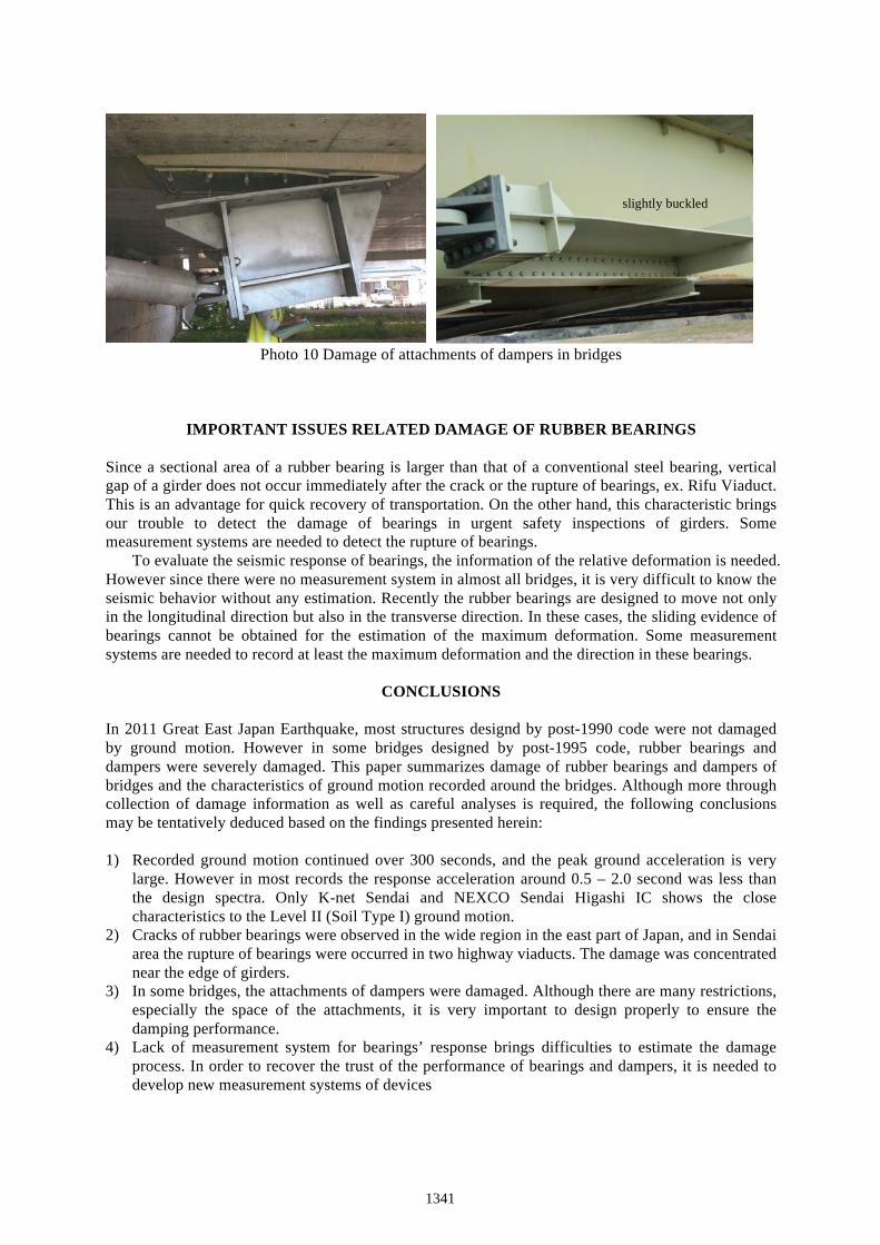
Photo 10 Damage of attachments of dampers in bridges
IMPORTANT ISSUES RELATED DAMAGE OF RUBBER BEARINGS Since a sectional area of a rubber bearing is larger than that of a conventional steel bearing, vertical gap of a girder does not occur immediately after the crack or the rupture of bearings, ex. Rifu Viaduct. This is an advantage for quick recovery of transportation. On the other hand, this characteristic brings our trouble to detect the damage of bearings in urgent safety inspections of girders. Some measurement systems are needed to detect the rupture of bearings.
To evaluate the seismic response of bearings, the information of the relative deformation is needed. However since there were no measurement system in almost all bridges, it is very difficult to know the seismic behavior without any estimation. Recently the rubber bearings are designed to move not only in the longitudinal direction but also in the transverse direction. In these cases, the sliding evidence of bearings cannot be obtained for the estimation of the maximum deformation. Some measurement systems are needed to record at least the maximum deformation and the direction in these bearings.
CONCLUSIONS In 2011 Great East Japan Earthquake, most structures designd by post-1990 code were not damaged by ground motion. However in some bridges designed by post-1995 code, rubber bearings and dampers were severely damaged. This paper summarizes damage of rubber bearings and dampers of bridges and the characteristics of ground motion recorded around the bridges. Although more through collection of damage information as well as careful analyses is required, the following conclusions may be tentatively deduced based on the findings presented herein: 1) Recorded ground motion continued over 300 seconds, and the peak ground acceleration is very
large. However in most records the response acceleration around 0.5 – 2.0 second was less than the design spectra. Only K-net Sendai and NEXCO Sendai Higashi IC shows the close characteristics to the Level II (Soil Type I) ground motion.
2) Cracks of rubber bearings were observed in the wide region in the east part of Japan, and in Sendai area the rupture of bearings were occurred in two highway viaducts. The damage was concentrated near the edge of girders.
3) In some bridges, the attachments of dampers were damaged. Although there are many restrictions, especially the space of the attachments, it is very important to design properly to ensure the damping performance.
4) Lack of measurement system for bearings’ response brings difficulties to estimate the damage process. In order to recover the trust of the performance of bearings and dampers, it is needed to develop new measurement systems of devices
slightly buckled
1341

ACKNOWLEDGMENTS The author expresses their sincere appreciation for a number of organizations and persons for their kind support and cooperation for the field damage investigation. Special appreciation is extended to Mr. Hirose of NEXCO East and Mr. Namikawa of Metropolitan Expressway.
REFERENCES Kawashima, K. (2000). “Seismic design and retrofit of bridges”, Key note presentation, 12th World
Conference on Earthquake Engineering, pp. 1-20, Paper No. 1818, 2000. Japan Road Association (1997). “Specifications for highway bridges, Part V Seismic design.” Maruzen,
Japan. Maeda, T. and Koyamada, K. (2011). “Damage of Bridges in 2001 Great East Japan Earthquake. (in
Japanese)” Proc. of 29th Japan Road Congress, Paper No. 2009, 2011.
1342