Prefabricated Steel Buildings Manufacturers & Suppliers in UAE
- 1 -
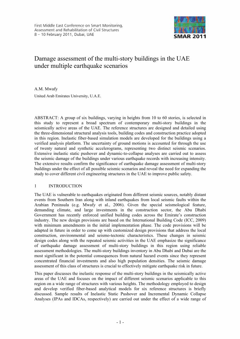
Damage assessment of the multi-story buildings in the UAE under multiple earthquake scenarios
A.M. Mwafy
United Arab Emirates University, U.A.E.
ABSTRACT: A group of six buildings, varying in heights from 10 to 60 stories, is selected in this study to represent a broad spectrum of contemporary multi-story buildings in the seismically active areas of the UAE. The reference structures are designed and detailed using the three-dimensional structural analysis tools, building codes and construction practice adopted in this region. Inelastic fiber-based simulation models are developed for the buildings using a verified analysis platform. The uncertainty of ground motions is accounted for through the use of twenty natural and synthetic accelerograms, representing two distinct seismic scenarios. Extensive inelastic static pushover and dynamic-to-collapse analyses are carried out to assess the seismic damage of the buildings under various earthquake records with increasing intensity. The extensive results confirm the significance of earthquake damage assessment of multi-story buildings under the effect of all possible seismic scenarios and reveal the need for expanding the study to cover different civil engineering structures in the UAE to improve public safety.
1 INTRODUCTION
The UAE is vulnerable to earthquakes originated from different seismic sources, notably distant events from Southern Iran along with inland earthquakes from local seismic faults within the Arabian Peninsula (e.g. Mwafy et al., 2006). Given the special seismological feature, demanding climate, and large investments in the construction sector, the Abu Dhabi Government has recently enforced unified building codes across the Emirate’s construction industry. The new design provisions are based on the International Building Code (ICC, 2009) with minimum amendments in the initial implementation phase. The code provisions will be adapted in future in order to come up with customized design provisions that address the local construction, environmental and seismo-tectonic characteristics. These changes in seismic design codes along with the repeated seismic activities in the UAE emphasize the significance of earthquake damage assessment of multi-story buildings in this region using reliable assessment methodologies. The multi-story buildings inventory in Abu Dhabi and Dubai are the most significant in the potential consequences from natural hazard events since they represent concentrated financial investments and also high population densities. The seismic damage assessment of this class of structures is crucial to effectively mitigate earthquake risk in future.
This paper discusses the inelastic response of the multi-story buildings in the seismically active areas of the UAE and focuses on the impact of different seismic scenarios applicable to this region on a wide range of structures with various heights. The methodology employed to design and develop verified fiber-based analytical models for six reference structures is briefly discussed. Sample results of Inelastic Static Pushover and Incremental Dynamic Collapse Analyses (IPAs and IDCAs, respectively) are carried out under the effect of a wide range of

- 2 -
natural and artificially generated ground motions are presented to provide insight into the seismic behavior of typical multi-story buildings (10 to 60 stories high) in the UAE.
2 SIMULATION MODELS OF REFERENCE STRUCTURES
2.1 Structural design
The six reference structures have the same layout shown in Figure 1. Each building consists of two basements, a ground story, and a number of typical stories. The height of all floors is 3.2 meters except for the ground story, which is 4.5 meters. The total height of the six buildings is therefore 65.3, 97.3, 129.3, 161.3 and 193.3 meters, respectively. The permanent loads include the self-weight in addition to a superimposed dead load of 4.0 kN/m2. The live load is 2.0 kN/m2 except for stairs and exit ways, which is 4.8 kN/m2. Wind loads are estimated using ASCE/SEI 7-05 (2006) based on a basic wind speed of 45 m/s and an exposure category C. Equivalent mapped spectral accelerations are adopted based on a site class D (stiff soil) and used to calculate the seismic loads according to ASCE/SEI 7-05 (2006) and previous hazard assessment studies for Dubai (Abdalla and Al-Homoud, 2004; Mwafy et al., 2006). Detailed three-dimensional (3D) models are developed for the six investigated buildings using the structural analysis program ETABS (CSI, 2008). The buildings are proportioned and detailed according to various load combinations and design provisions recommended by the ACI building code (ACI, 2005). Yield strength of reinforcing steel is 460 MPa. A constant concrete strength of 45 MPa is used for floor slabs and beams, while it varies along the height of shear walls from 45 to 60 MPa. The cross-sections of walls and the corresponding reinforcement also vary along the building height. The floor slab systems comprise of a 0.28 meter cast-in-place flat slabs with a beam at the perimeter. Figure 1 shows the 3D models employed in the design of the buildings, while Table 1 summarizes the sizes and concrete strength (fc') of vertical structural members. Additional design information and detailed structural drawings of the reference structures are available elsewhere (Mwafy, 2009 & 2010).
Figure 1. Three-dimensional analytical models used in design along with the building layout, which shows different lateral force-resisting systems in the longitudinal and transverse directions.
2.2 Analytical modeling
The IPAs and IDCAs of the reference structures are performed using ZEUS-NL (Elnashai et al., 2010). The program was developed at Imperial College London and University of Illinois at
CO
RE
CO
RE
CO
RE
CO
RE
SW1 SW1 SW1 SW1
SW2
SW2
SW2
SW2
SW1 SW1 SW1 SW1
42.0 m
8.4 m 8.4 m 8.4 m 8.4 m 8.4 m
8.4
m
8.4
m
7.4
m
24.2
m
RC shear walls
SW3 SW3
SW3SW3
Flat slab system
~
Lat
eral
for
ce r
esis
ting
syst
em
in th
e lo
ngit
udi
nal
dire
ctio
n
Lateral force resisting system in the transverse direction

- 3 -
Urbana-Champaign and has been extensively verified against tests carried out in Europe and the US. The fiber-based idealization adopted in the current study effectively monitors the inelastic response of each frame element over two Gauss sections through the integration of the nonlinear stress-strain response of different fibers in which the section is subdivided, as shown in Figure 2. Three cubic elasto-plastic frame elements capable of representing the spread of yielding and cracking are used to model each structural member, which enable modeling different arrangements of reinforcing steel. Two rigid arms are utilized to connect the slab/beam ends with the framing wall. RC rectangular, T, flexural wall, hollow core and steel rectangular cress sections are selected from the ZEUS-NL library to model slabs, connecting beams, shear walls, cores and rigid arms, respectively. The concrete response is represented using a uniaxial constant confinement concrete model, while a bilinear elasto-plastic model represents the reinforcing steel (Elnashai et al., 2010). Actual (mean) material strengths are employed in the ZEUS-NL models for assessment of the reference structures.
Table 1. Periods of vibration in the transverse direction (sec.), concrete strength (fc', MPa) and sizes of vertical structural members (mm) of the reference structures.
Building Periods (1st, 2nd,
3rd) Member Characteristics
Story
2nd Bas.-3 4-8 9-18 19-28 29-38 39-48 49-58
10SB 0.63, 0.12, 0.08
SW Cross section 300x1600 300x1600 Concrete strength 36 36 CORE Thickness 250 200 Concrete strength 36 36 20SB 1.55,
0.35, 0.14
SW Cross section 350x3000 350x3000 300x3000 Concrete strength 36 36 36 CORE Thickness 300 250 200 Concrete strength 36 36 36 30SB 2.56,
0.65, 0.28
SW Cross section 350x4000 350x4000 300x4000 250x4000 Concrete strength 40 40 36 36 CORE Thickness 300 300 250 200 Concrete strength 40 40 40 36 40SB 3.69,
0.98, 0.44
SW Cross section 400x5000 400x5000 350x5000 300x5000 250x5000 Concrete strength 48 48 40 36 36 CORE Thickness 350 350 300 250 200 Concrete strength 48 48 40 40 36 50SB 5.10,
1.38, 0.63
SW Cross section 450x5000 450x5000 400x5000 350x5000 300x5000 250x5000 Concrete strength 48 48 40 40 36 36 CORE Thickness 400 400 350 300 250 200 Concrete strength 48 48 40 40 36 36 60SB 6.06,
1.68, 0.77
SW Cross section 500x5000 500x5000 450x5000 400x5000 350x5000 300x5000 250x5000 Concrete strength 56 56 48 40 40 36 36 CORE Thickness 450 450 400 350 300 250 200 Concrete strength 56 56 48 40 40 36 36
Since performing 3D IDCAs of multi-story structures is computationally demanding, particularly with the broad range of buildings and input ground motions employed in the present study, a two-dimensional idealization is adopted to assess the response of the reference structures. It is assumed that four lateral-force-resisting systems are in the transverse directions of each building. Each of these framing systems, which is loaded with 25% of the total mass of the building, consist of two external shear walls (SW1) and an internal core, as shown in Figure 1. The two framing systems at the left and right margins are assumed to resist gravity loads only. It is also clear from Figure 1 that only one framing system effectively resists the lateral forces in the longitudinal direction. The latter system consists of all internal cores and the shear walls SW2. Other walls are conservatively assumed not participating in resisting the lateral forces in the longitudinal direction. Therefore, in total, twelve framing systems are modeled using ZEUS-NL to represent the six buildings (one model for each building in both the longitudinal and transverse directions). The 3D ETABS models developed for the design of the

- 4 -
buildings were employed to verify the ZEUS-NL 2D idealizations before executing IPAs and IDCAs. The latter platform is exclusively used for predicting the inelastic seismic response of the six investigated buildings. The results of this verification and additional information regarding the analytical modeling are available elsewhere (Mwafy, 2009 & 2010).
(a) Concrete and reinforcing steel hysteresis modeles
(c) Cubic elasto-plastic frame element
Figure 2. Ingredients of the ZEUS-NL (Elnashai et al., 2010) fiber-based models: (a) material models, (b) sample of concrete sections, and (c) elasto-plastic frame element.
3 ESTIMATION OF LATERAL CAPACITY
Nonlinear static analyses are performed to evaluate the lateral capacity of the reference structures, which enables comparisons with the demand predicted from IDCA. Gravity loads are applied before the application of lateral loads, which are continuously increased up to the satisfaction of the collapse limit state or the detection of significant spread of yielding and cracking. Two lateral load distributions are employed in IPA. The first load is a uniform pattern, representing lateral forces that are proportional with mass. The second lateral load is an inverted triangular load, resembling the first mode shape. Mwafy el al. (2006) concluded that the uniform lateral load distribution can be used to obtain a conservative estimate of initial stiffness and lateral capacity of high-rise buildings. Based on this conclusion, which is supported by the earlier study of Mwafy and Elnashai (2001), it was decided to use the uniform lateral load to estimate the lateral capacity of the reference structures. Moreover, the response of the 3D models developed for the design as well as IPA results indicated that the differences in response between the transverse and longitudinal directions of the buildings are insignificant. Although twelve framing systems were modeled using ZEUS-NL to represent the lateral force-resisting-systems in the longitudinal and transverse directions, the six frames representing the buildings in the transverse direction are employed in subsequent sections to predict capacity and demand.
The capacity envelopes of the six reference structures are depicted in Figure 3. The first indication of yielding in walls and horizontal members as well the global yielding and ultimate capacity are also shown. The global yield is estimated from an elastic-perfectly plastic idealization of the real capacity envelop. It is shown from Figure 3 that the first yield gradually shifts from walls to horizontal members with increasing the building height. The behavior of the 10-30 story buildings is governed by localized yielding at the base of shear walls. First yielding in horizontal members of these buildings is observed at higher lateral loads compared with yielding in shear walls, particularly for the 10- and 20-story buildings. This is unlike the response of other structures. Clearly, shifting the first indication of yield to be at a higher base shear level and in slabs/beams rather than in shear walls, as shown from the response of the 40- to 60-story structures, is more favorable. Moreover, the results depicted in Figure 3 indicate that the structural overstrength, defined as the ratio of the ultimate capacity to the seismic design
Gauss sections
L0.58 L0.21 L 0.21 L
Concrete andsteel layers
Concrete and steel fibers
(b) RC flexural wall section
Unconfined
2
b
Partially confined Fully confined
c
fc
Envelope curve
Unloading curve
Reloading curve
Stre
ss
Stress
Envelope curve
Unloading curve
Reloading curve
Strain
Stre
ss
E
Eh
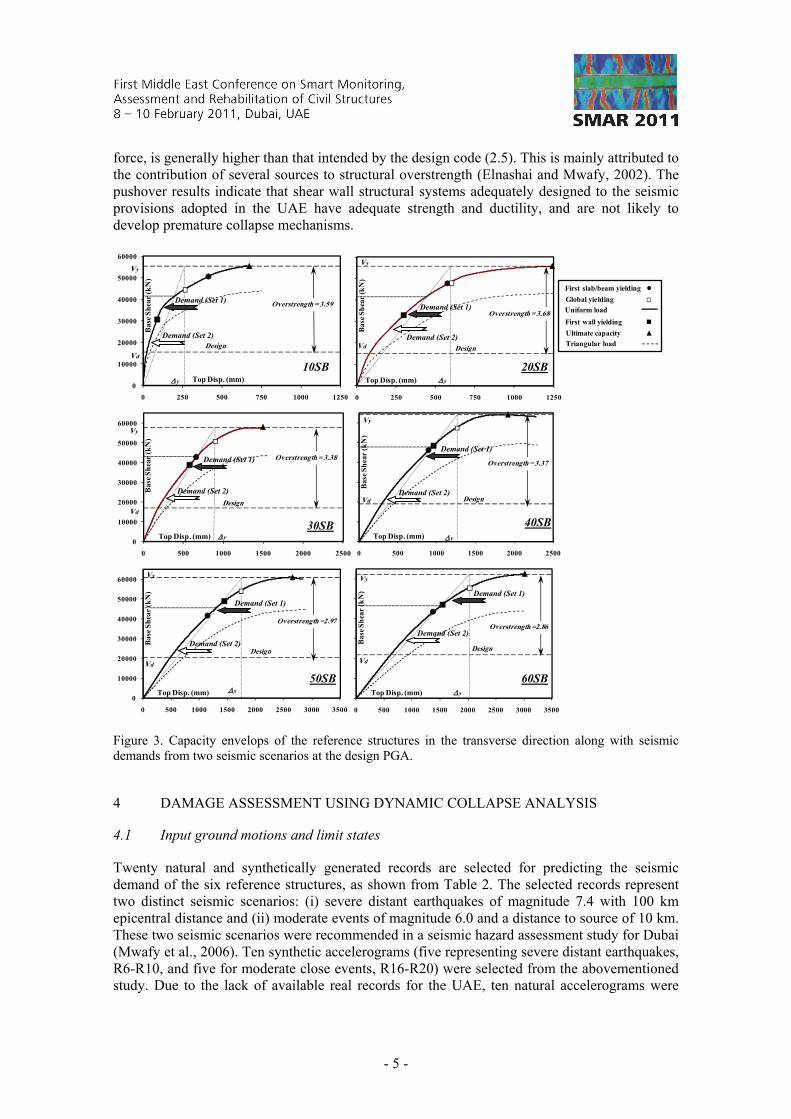
- 5 -
force, is generally higher than that intended by the design code (2.5). This is mainly attributed to the contribution of several sources to structural overstrength (Elnashai and Mwafy, 2002). The pushover results indicate that shear wall structural systems adequately designed to the seismic provisions adopted in the UAE have adequate strength and ductility, and are not likely to develop premature collapse mechanisms.
0
10000
20000
30000
40000
50000
60000
0 250 500 750 1000 1250
Bas
e S
hea
r (k
N)
Top Disp. (mm)
Design
Overstrength = 3.59
Vy
y
Vd
0 250 500 750 1000 1250
Bas
e S
hea
r (k
N)
Top Disp. (mm)
Design
Overstrength = 3.68
Vy
y
Vd
0
10000
20000
30000
40000
50000
60000
0 500 1000 1500 2000 2500
Bas
e S
hea
r (k
N)
Top Disp. (mm)
Design
Vy
y
Vd
Overstrength = 3.38
0 500 1000 1500 2000 2500
Bas
e S
hea
r (k
N)
Top Disp. (mm)
Design
Overstrength = 3.37
Vy
y
Vd
0
10000
20000
30000
40000
50000
60000
0 500 1000 1500 2000 2500 3000 3500
Bas
e S
hea
r (k
N)
Top Disp. (mm)
Design
Overstrength =2.97
Vy
y
Vd
0 500 1000 1500 2000 2500 3000 3500
Bas
e S
hea
r (k
N)
Top Disp. (mm)
Design
Overstrength =2.86
Vy
y
Vd
Figure 3. Capacity envelops of the reference structures in the transverse direction along with seismic demands from two seismic scenarios at the design PGA.
4 DAMAGE ASSESSMENT USING DYNAMIC COLLAPSE ANALYSIS
4.1 Input ground motions and limit states
Twenty natural and synthetically generated records are selected for predicting the seismic demand of the six reference structures, as shown from Table 2. The selected records represent two distinct seismic scenarios: (i) severe distant earthquakes of magnitude 7.4 with 100 km epicentral distance and (ii) moderate events of magnitude 6.0 and a distance to source of 10 km. These two seismic scenarios were recommended in a seismic hazard assessment study for Dubai (Mwafy et al., 2006). Ten synthetic accelerograms (five representing severe distant earthquakes, R6-R10, and five for moderate close events, R16-R20) were selected from the abovementioned study. Due to the lack of available real records for the UAE, ten natural accelerograms were
10SB 20SB
30SB 40SB
50SB 60SB
Demand (Set 1)
Demand (Set 2)
Demand (Set 1)
Demand (Set 2)
Demand (Set 1)
Demand (Set 2)
Demand (Set 1)
Demand (Set 2)
Demand (Set 1)
Demand (Set 2)
Demand (Set 1)
Demand (Set 2)
First slab/beam yielding ●Global yielding
Uniform load
First wall yielding
Ultimate capacity ▲
Triangular load
▲
- 6 -
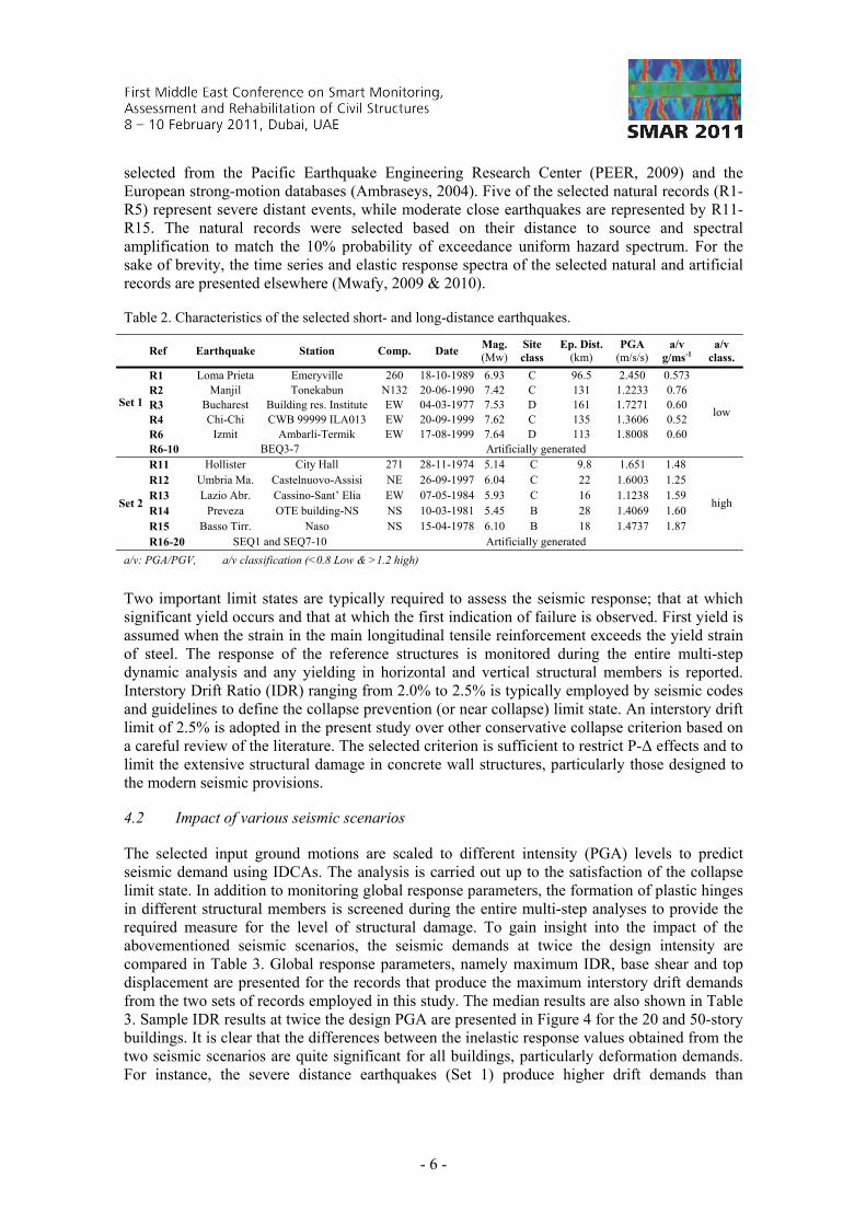
selected from the Pacific Earthquake Engineering Research Center (PEER, 2009) and the European strong-motion databases (Ambraseys, 2004). Five of the selected natural records (R1-R5) represent severe distant events, while moderate close earthquakes are represented by R11-R15. The natural records were selected based on their distance to source and spectral amplification to match the 10% probability of exceedance uniform hazard spectrum. For the sake of brevity, the time series and elastic response spectra of the selected natural and artificial records are presented elsewhere (Mwafy, 2009 & 2010).
Table 2. Characteristics of the selected short- and long-distance earthquakes.
Ref Earthquake Station Comp. Date
Mag. (Mw)
Site class
Ep. Dist. (km)
PGA (m/s/s)
a/v g/ms-1
a/v class.
Set 1
R1 Loma Prieta Emeryville 260 18-10-1989 6.93 C 96.5 2.450 0.573
low
R2 Manjil Tonekabun N132 20-06-1990 7.42 C 131 1.2233 0.76 R3 Bucharest Building res. Institute EW 04-03-1977 7.53 D 161 1.7271 0.60 R4 Chi-Chi CWB 99999 ILA013 EW 20-09-1999 7.62 C 135 1.3606 0.52 R6 Izmit Ambarli-Termik EW 17-08-1999 7.64 D 113 1.8008 0.60 R6-10 BEQ3-7 Artificially generated
Set 2
R11 Hollister City Hall 271 28-11-1974 5.14 C 9.8 1.651 1.48
high
R12 Umbria Ma. Castelnuovo-Assisi NE 26-09-1997 6.04 C 22 1.6003 1.25 R13 Lazio Abr. Cassino-Sant’ Elia EW 07-05-1984 5.93 C 16 1.1238 1.59 R14 Preveza OTE building-NS NS 10-03-1981 5.45 B 28 1.4069 1.60 R15 Basso Tirr. Naso NS 15-04-1978 6.10 B 18 1.4737 1.87 R16-20 SEQ1 and SEQ7-10 Artificially generated
a/v: PGA/PGV, a/v classification (<0.8 Low & >1.2 high)
Two important limit states are typically required to assess the seismic response; that at which significant yield occurs and that at which the first indication of failure is observed. First yield is assumed when the strain in the main longitudinal tensile reinforcement exceeds the yield strain of steel. The response of the reference structures is monitored during the entire multi-step dynamic analysis and any yielding in horizontal and vertical structural members is reported. Interstory Drift Ratio (IDR) ranging from 2.0% to 2.5% is typically employed by seismic codes and guidelines to define the collapse prevention (or near collapse) limit state. An interstory drift limit of 2.5% is adopted in the present study over other conservative collapse criterion based on a careful review of the literature. The selected criterion is sufficient to restrict P-Δ effects and to limit the extensive structural damage in concrete wall structures, particularly those designed to the modern seismic provisions.
4.2 Impact of various seismic scenarios
The selected input ground motions are scaled to different intensity (PGA) levels to predict seismic demand using IDCAs. The analysis is carried out up to the satisfaction of the collapse limit state. In addition to monitoring global response parameters, the formation of plastic hinges in different structural members is screened during the entire multi-step analyses to provide the required measure for the level of structural damage. To gain insight into the impact of the abovementioned seismic scenarios, the seismic demands at twice the design intensity are compared in Table 3. Global response parameters, namely maximum IDR, base shear and top displacement are presented for the records that produce the maximum interstory drift demands from the two sets of records employed in this study. The median results are also shown in Table 3. Sample IDR results at twice the design PGA are presented in Figure 4 for the 20 and 50-story buildings. It is clear that the differences between the inelastic response values obtained from the two seismic scenarios are quite significant for all buildings, particularly deformation demands. For instance, the severe distance earthquakes (Set 1) produce higher drift demands than

- 7 -
moderate proximate events (Set 2) by more than 300%. Figure 3 also compares between the capacity and average seismic demands at the design PGA from the two seismic scenarios. The significant difference between the demands obtained from the two seismic scenarios is clear. Generally, the seismic response from both sets of ground motions is considered satisfactory since the observed IDRs at the design and twice the design PGA are below the code recommended value (2%) as well as the adopted collapse limit state (2.5%)
The differences in seismic behavior of the reference structures from ground motion Set 1 and Set 2 is justified by the high contribution of the second mode of vibration, despite its lower mass participation, when the high-rise buildings is exited by severe far earthquakes. The response under the moderate close events (Set 2) is insignificant due to the lower spectral amplification corresponding to both first and second modes of vibration. Figure 5 compares between the vulnerability curves obtained from the two seismic scenarios employed in the present study for a sample building. It is clear that the slops are steeper and the probability of exceeding various limit states is much higher under the effect of Set 1 compared with Set 2. The seismic response of the reference structures under the Set 2 records when scaled to the design PGA is insignificant, particularly for long-period structures. Although the vulnerability of high-rise buildings in the UAE to severe distant earthquakes was confirmed from a previous study carried out by the author for a 54-story building using limited input ground motions (Mwafy et al., 2006), the present study clearly confirms that this conclusion applies to a wide range of multi-story buildings ranging from 10 to 60 stories.
Table 3. Seismic demands from two sets of input ground motions at twice the design PGA.
Record ID V D Record ID V D Record ID V D 10-story Building 20-story Building 30-story Building
Set 1 (10 Recs)
Max. Manjil 1.44 56.7 396 BEQ4 1.54 46.6 771 Chi-Chi 1.42 60.3 1141Median 1.35 54.25 389 1.06 53.5 547 0.91 61.5 693
Set 2 (10 Recs)
Max. Lazio A. 0.55 37.5 139 SEQ9 0.37 41.8 121 SEQ10 0.32 36.0 121 Median 0.40 34.52 100 0.33 41.9 115 0.23 37.9 79
Median of 20 records 0.77 43.90 201 0.55 47.4 244 0.41 49.8
40-story Building 50-story Building 60-story Building Set 1 (10 Recs)
Max. Chi-Chi 1.20 89.2 1250 BEQ4 1.34 61.2 1184 Chi-Chi 1.13 98.0 1322Median 0.96 68.9 683 0.88 68.1 755 0.89 91.5 858
Set 2 (10 Recs)
Max. Umbria M. 0.34 45.4 78 SEQ8 0.37 43.0 178 SEQ7 0.26 67.4 135 Median 0.25 43.8 77 0.23 42.4 84 0.18 57.3 93
Median of 20 records 0.52 54.9 225 0.49 56.1 204 0.46 72.6 165 ID: Maximum interstory drift (%) V: Maximum base shear (MN) D: Maximum top displacement (mm)
-2-1012
Stor
y
IDR (%)
10
20
5
15
Set 2Set 1
Median of Set 1
Median of Set 2
-2-1012
Stor
y
IDR (%)
20
50
10
30
Set 2Set 1
Median of Set 1
Median of Set 2
40
0
0.2
0.4
0.6
0.8
1
0 0.5 1 1.5 2
P(L
imit
Sta
te|G
MI)
PGA (g)
IO - Set 1LS - Set 1CP - Set 1IO - Set 2LS - Set 2CP - Set 2
30SB-Set 1
30SB-Set 1
Figure 4. Maximum and median interstory drift of the 20 and 50-story buildings at twice the design PGA from two earthquake scenarios.
Figure 5. Vulnerability curves of the 30-story building obtained from IDCAs using two seismic scenarios.
- 8 -
5 CONCLUSIONS
This paper focused on assessing the impact of various seismic scenarios on the multi-story buildings with shear walls since they are widespread in the UAE and represent concentrated economic and human assets. The approach used to design and develop fiber-based simulation models for six reference structures was discussed and sample results obtained from Inelastic Pushover Analyses (IPAs) and Incremental Dynamic Collapse Analyses (IDCAs) were presented. Tracing the capacity curves of the reference structures indicated that first yielding gradually shifts from walls to horizontal structural members with increasing the building height. The reference structures did not develop unfavorable failure mechanisms. The overstrength factors were above the value intended by the design code. IDCA results provided insight into the inelastic seismic response of the reference structures and enabled assessing the seismic response under the effect of two sets of ground motions representing two different seismic scenarios. The vulnerability of multi-story buildings ranging from 10 to 60 stories in the earthquake-prone areas of the UAE to severe distant earthquakes was confirmed in this study. Unlike moderate close events, severe distant earthquakes have high amplifications in the long period range, and hence have more impact on seismic response. The presented results confirm the importance of systematic vulnerability assessment for a population of buildings and the need for expanding the study to cover other classes of structure in this region.
6 ACKNOWLEDGEMENT
This study was supported by the Research Affairs at the UAE University under a contracts no. 07-34-07-11/07 and 07-01-07-11/09. The author would also like to thank Eng. A. Ashry for his contribution to this work.
7 REFERENCES
Abdalla, JA, and Al-Homoud, AS. 2004. Seismic hazard assessment of United Arab Emirates and its surroundings. Journal of Earthquake Engineering, 8: 17-37.
Ambraseys, NN, Douglas, J, Sigbj¨ornsson, R, Berge-Thierry, C, Suhadolc, P, Costa, G et al. 2004. Dissemination of European strong-motion data, vol. 2, using strong-motion datascape navigator, CD ROM collection. Engineering and Physical Sciences Research Council, United Kingdom.
ACI. 2005. Building Code Requirements for Structural Concrete and Commentary (318-05). American Concrete Institute, Detroit, Michigan.
ASCE. 2006. Minimum Design Loads for Buildings and Other Structures, ASCE Standard ASCE/SEI 7-05 Including Supplement No. 1 American Society of Civil Engineers, Reston, VA.
CSI. 2008. ETABS - Integrated building design software. Computers and Structures, Inc., Berkeley, CA. Elnashai, AS, Papanikolaou, V, and Lee D. 2010. Zeus-NL - A system for inelastic analysis of structures -
User manual, Mid-America Earthquake Center, Univ. of Illinois at Urbana-Champaign, Urbana, IL. Elnashai, AS, and Mwafy, AM. 2002. Overstrength and force reduction factors of multistorey reinforced-
concrete buildings. The Structural Design of Tall Buildings, 11: 329-51. ICC. 2009. International building code, International Code Council, Country Club Hills, IL. Mwafy, AM. 2010. Analytically-derived fragility relationships for the modern high-rise buildings in the
UAE. Structural Design of Tall and Special Buildings, In press. Mwafy, AM. 2009. Seismic design response factors and vulnerability functions of typical UAE buildings,
Phase I: Response factors: UAE University, Al Ain, UAE. Mwafy, AM, Elnashai, AS, Sigbjornsson, R, and Salama, A. 2006. Significance of severe distant and
moderate close earthquakes on design and behavior of tall buildings. Structural Design of Tall and Special Buildings, 15: 391-416.
Mwafy, AM, and Elnashai AS. 2001. Static pushover versus dynamic collapse analysis of RC buildings. Engineering Structures, 23: 407-24.
PEER. 2009. PEER NGA database. Pacific Earthquake Engineering Research Center, University of California, Berkeley, California.