
Dam Safety Guidance Manual - Arkansasstatic.ark.org/eeuploads/anrc/DamSafetyBook2017revised.pdf ·...
122
A R K A N S A S N A T U R A L R E S O U R C E S C O M M I S S I O N Dam Safety Guidance Manual for Arkansas Dam Owners Published by the Arkansas Natural Resources Commission Dam Safety Program
Transcript of Dam Safety Guidance Manual - Arkansasstatic.ark.org/eeuploads/anrc/DamSafetyBook2017revised.pdf ·...
ARKAN
SAS
NATURAL RESOURCES CO
MM
ISSION
Dam SafetyGuidance Manual for Arkansas Dam Owners
Published by the
Arkansas Natural Resources CommissionDam Safety Program
Arkansas Natural Resources Commission - Dam Safety Program 1
Acknowledgement
Dam safety has attracted a great deal of attention in recent years, and in preparing this manual, information from a number of sources was used. The National Dam Safety Pro-gram, instituted in response to several major dam failures in the early 1970’s, focused on the problem nationwide. Federal Emergency Management Agency (FEMA) has taken the lead in providing assistance to states in promoting dam safety. The National Dam Safety Program Act of 1996 continues to reinforce the commitment by the Federal Government to dam safety.
Special recognition is given to the Federal Emergency Management Agency (FEMA) and the Association of State Dam Safety Officials (ASDSO) for their leadership in developing effective dam safety programs and policies for the furtherance of dam safety. Their dili-gence in assisting the U.S. dam safety community was an important factor in the issuance of the FEMA grant.
The cooperation of the owners of dams within Arkansas is essential to the success of the State’s dam safety effort. The ultimate purpose of such a program is the protection of the lives and property of citizens of Arkansas.
Photographs courtesy of Mark Harrison or as noted.
This publication was funded by a dam safety grant from the Federal Emergency Management Agency (FEMA).
Cover Photo: Huckleberry Creek Dam in Pope County
This manual is intended to provide information regarding best practices with respect to management of a dam safety program for a dam or portfolio of dams. This manual does not supersede in any manner the provisions of the Arkansas Natural Resources Commission (ANRC) Title 7 “Rules Governing Design and Operation of Dams” or Arkansas law regulating the construction and maintenance of dams.
A special thanks is extended to Yohanes Sugeng, Manager of the Dam Safety Program of the Oklahoma Water Resources Board (OWRB), and to the staff of the OWRB. The majority of this manual was adapted from material in the “Dam Safety Guidance Manual for Oklahoma Dam Owners” and we are grateful to Mr. Sugeng and OWRB for sharing this information.
Arkansas Natural Resources Commission - Dam Safety Program 2
Contents DAM SAFETY: AN OWNER’S GUIDANCE MANUAL ............................... 4Introduction to Dam Safety .....................................................4Hazards, Risk, Failures ..............................................................5Inspection Guidelines ...............................................................5Instrumentation and Monitoring Guidelines ........................5Maintenance Guidelines ...........................................................6Emergency Action Plan Guidelines ........................................6Operation Plan Guidelines .......................................................7Measures to Reduce the Consequences of Dam Failure .................................................7
Water Retention Ability ..........................................................14Seepage Through a Dam ........................................................15Seepage Around a Dam ..........................................................15Release of Water .......................................................................15Principal or Mechanical Spillway ..........................................15Drawdown Facility ..................................................................16Emergency (Auxiliary) Spillway ............................................16
CHAPTER 3: HAZARDS, RISKS, FAILURES ........................................17General ......................................................................................17Hazards as Sources of Risks ...................................................17Natural Hazards That Threaten Dams .................................18Hazards from Human Activity ..............................................19Site-Specific Structural Risk ...................................................20Sources of Dam Failure ...........................................................21Three Categories of Structural Failure..................................21Failures ......................................................................................21Age and Its Relation to Failure...............................................22
CHAPTER 4: DEVELOPING A PERSONAL SAFETY PROGRAM .........24Objectives of a Safety Program ..............................................24Guidelines for Assessing Existing Conditions .....................24Procedural Guidelines – A Source Book ..............................26Documenting the Safety Program .........................................26
CHAPTER 5: INSPECTION GUIDELINES ............................................27Introduction .............................................................................27Organizing for Inspection ......................................................28Embankment Dams and Structures ......................................29Upstream Slope ........................................................................30Downstream Slope ..................................................................31Crest ..........................................................................................32Seepage Areas ...........................................................................33Concrete Dams and Structures ..............................................34Spillways ...................................................................................36Procedure for Inspection of the Spillway .............................40Inlets, Outlets, and Drains .....................................................41Inspecting the outlet system ..................................................43General Areas ...........................................................................44
DAM SAFETY: OWNER’S GUIDANCE MANUAL
CHAPTER 1: AN APPROACH TO DAM SAFETY ................................... 8General ........................................................................................8Urgency for Safety .....................................................................8Dam Ownership and Safety .....................................................8Role of the Dam Owner in Dam Safety ..................................9The Role of Consultants in Dam Safety ...............................10Role of the Arkansas Natural Resources Commission .......11
CHAPTER 2: INTRODUCTON TO DAMS ............................................12General ......................................................................................12The Watershed System ............................................................12Types of Dams ..........................................................................13Components .............................................................................13Construction Materials ...........................................................13
MA
RK H
ARR
ISO
N, O
KLAHOMA
CO
NSE
RVAT
ION
CO
MM
ISSI
ON

Arkansas Natural Resources Commission - Dam Safety Program 73
CH
APTER 7
CHAPTER 7:
Maintenance Inspection Guidelines7General
A good maintenance program will pro-tect a dam against deterioration and prolong its life. A poorly maintained
dam will deteriorate, and may fail. Nearly all the components of a dam and the materials used for its construction are susceptible to damaging de-terioration if not properly maintained. A good maintenance program protects not only you, the owner, but the general public as well. Moreover, the cost of a proper maintenance program is small compared to the costs of major repairs, loss of life and property, and litigation.
Develop a basic maintenance program based primarily on systematic and frequent inspec-tions. Inspections, as noted in Chapter 5, should be performed at least monthly and after major floods or earthquakes. During each inspection, refer to a checklist of items that call for main-tenance.
Maintenance Priorities
MAINTENANCE SHOULD NEVER BE NEGLECTED.
The following outline lists, by relative priority, the various problems or conditions that might be encountered in a dam that has deteriorated from lack of maintenance.
IMMEDIATE MAINTENANCEThe following conditions are critical and call for immediate attention:
• Adamabouttobeovertoppedorbeingovertopped
• Adamabouttobebreached(byprogressiveerosion,slopefailure,orothercircumstances)
• Adamshowingsignsofpipingorinternalerosionindicatedbyincreasinglycloudyseepageorothersymptoms
• Aspillwaybeingblockedorotherwiserenderedinoperable,orhavingnormaldischargerestricted
• Evidenceofexcessiveseepageappearinganywhereatthedamsite(anembankmentbecomingsaturated,seepageexitingonthedownstreamfaceofadam)increasinginvolume
Although the remedy for some critical problems may be obvious (such as clearing a blocked spillway), the problems listed above generally require the services of a professional engineer familiar with the construction and maintenance of dams. The emergency action plan (discussed in Chapter 8) should be activated when any of the above conditions are noted.
REQUIRED MAINTENANCE AT EARLIEST POSSIBLE DATEThe following maintenance should be completed as soon as possible after the defective condition is noted:
• Removeallunderbrushandtreesfromthedam,andestablishagoodgrasscover
• Fillanimalburrows
!
Arkansas Natural Resources Commission - Dam Safety Program74
• Repairlivestocktrailsandfencestokeeplivestockoffdam
• Restoreandreseederodedareasandgulliesonembankmentdams
• Repairdefectivespillways,gates,valves,andotherappurtenantfeatures
• Repairanyconcreteormetalcomponentsthathavedeteriorated,assoonasweatherpermits
CONTINUING MAINTENANCESeveral tasks should be performed continually:
• Routinemowingandgeneralmaintenance
• Maintenanceandfillingofanycracksandjointsonconcretedamsandinconcretespillways
• Observationofanyspringsorareasofseepage,comparingquantityandquality(clarity)withpriorobservations
• Inspectionofthedam(asdiscussedinChapter5)
• Monitoringofdevelopmentinthewatershedwhichwouldmateriallyincreaserunofffromstorms
• Monitoringofdevelopmentdownstreamandupdatingtheemergencynotificationplantoincludenewhousesorotheroccupiedstructureswithinthearea
Specific Maintenance Items
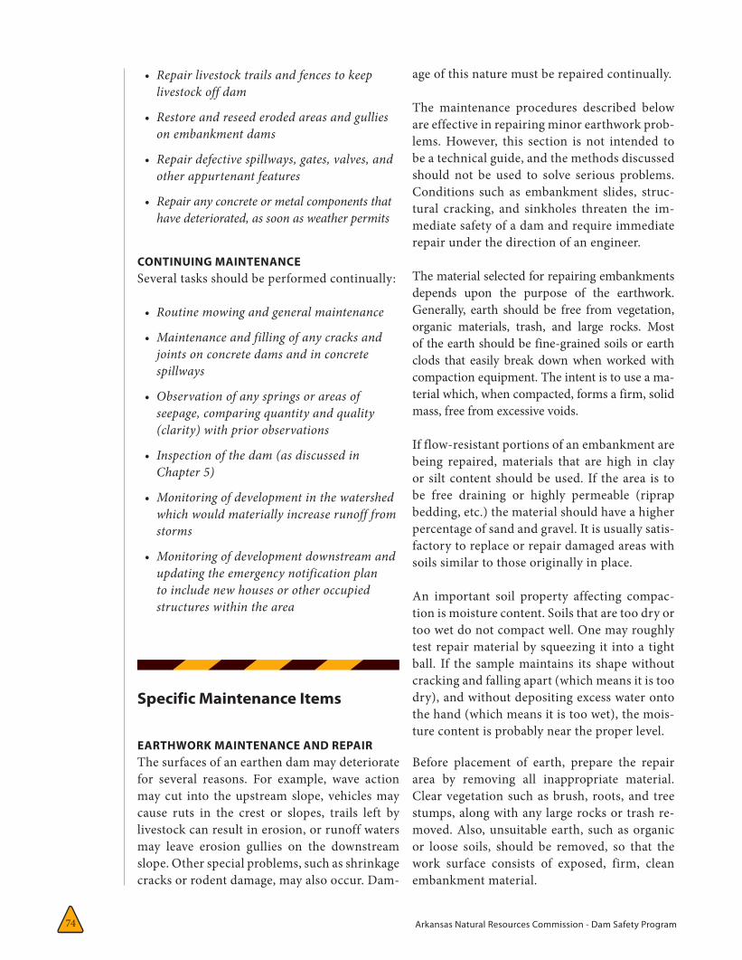
EARTHWORK MAINTENANCE AND REPAIRThe surfaces of an earthen dam may deteriorate for several reasons. For example, wave action may cut into the upstream slope, vehicles may cause ruts in the crest or slopes, trails left by livestock can result in erosion, or runoff waters may leave erosion gullies on the downstream slope. Other special problems, such as shrinkage cracks or rodent damage, may also occur. Dam-
age of this nature must be repaired continually.
The maintenance procedures described below are effective in repairing minor earthwork prob-lems. However, this section is not intended to be a technical guide, and the methods discussed should not be used to solve serious problems. Conditions such as embankment slides, struc-tural cracking, and sinkholes threaten the im-mediate safety of a dam and require immediate repair under the direction of an engineer.
The material selected for repairing embankments depends upon the purpose of the earthwork. Generally, earth should be free from vegetation, organic materials, trash, and large rocks. Most of the earth should be fine-grained soils or earth clods that easily break down when worked with compaction equipment. The intent is to use a ma-terial which, when compacted, forms a firm, solid mass, free from excessive voids.
If flow-resistant portions of an embankment are being repaired, materials that are high in clay or silt content should be used. If the area is to be free draining or highly permeable (riprap bedding, etc.) the material should have a higher percentage of sand and gravel. It is usually satis-factory to replace or repair damaged areas with soils similar to those originally in place.
An important soil property affecting compac-tion is moisture content. Soils that are too dry or too wet do not compact well. One may roughly test repair material by squeezing it into a tight ball. If the sample maintains its shape without cracking and falling apart (which means it is too dry), and without depositing excess water onto the hand (which means it is too wet), the mois-ture content is probably near the proper level.
Before placement of earth, prepare the repair area by removing all inappropriate material. Clear vegetation such as brush, roots, and tree stumps, along with any large rocks or trash re-moved. Also, unsuitable earth, such as organic or loose soils, should be removed, so that the work surface consists of exposed, firm, clean embankment material.
Arkansas Natural Resources Commission - Dam Safety Program 75
CH
APTER 7
Following cleanup, shape and dress the affected area so that the new fill can be compacted and will properly tie into the existing fill. If possible, trim slopes and roughen surfaces by scarifying or plowing to improve the bond between the new and existing fill and to provide a good base to compact against. Grade the slopes in a direction such that the soil ridges are parallel to the length of the dam—this will help to minimize or reduce rill erosion. Roughening in the wrong direction will likely increase rill erosion.
Place soils in loose layers up to eight inches thick and compact manually or mechanically to form a dense mass free from large rock or organic mate-rial. Maintain soil moisture in the proper range. The fill should be watered and mixed to the proper wetness or scarified and allowed to dry if too wet.
During backfilling, take care that the fill does not become too wet from rainstorm runoff. Di-rect runoff away from the work area and overfill repair areas so that the fill maintains a crown that will shed water. As mentioned earlier, oc-casionally minor cracks will form in an earthen dam because of surface drying. These are called desiccation (drying) cracks and should not be confused with structural or settlement cracks. Drying cracks are usually parallel to the main axis of the dam, typically near the upstream or downstream shoulders of the crest. These cracks often run intermittently along the length of the dam and may be up to four feet deep. Drying cracks can be distinguished from more serious structural cracks because the former are usually no wider than a few inches and have edges that are not offset vertically.
As a precaution, initially monitor suspected desiccation cracks with the same care used for other types of cracks. The problem area should be marked with survey stakes, and monitoring pins should be installed on either side of the crack to allow recording of any changes in width or vertical offset. Once you are satisfied that observed crack-ing is the result of shrinkage or drying, you may stop monitoring.
These cracks should close as climatic or soil
moisture conditions change. If they do not, it may be necessary to backfill the cracks to prevent entry of surface moisture, which could result in saturation of the dam. The cracks may be sim-ply filled with earth that is tamped in place with hand or tools. It is also recommended that the crest of a dam be graded to direct runoff waters away from areas damaged by drying cracks.
As Chapter 5 suggests, erosion is one of the most common maintenance problems at embank-ment structures. Erosion is a natural process and its continuous forces will eventually wear down almost any surface or structure. Periodic and timely maintenance is essential to prevent continuous deterioration and possible failure.
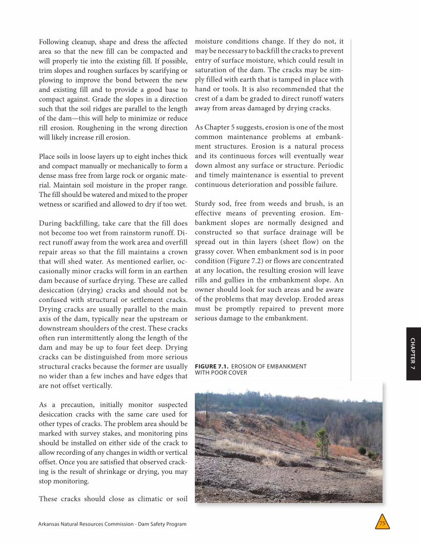
Sturdy sod, free from weeds and brush, is an effective means of preventing erosion. Em-bankment slopes are normally designed and constructed so that surface drainage will be spread out in thin layers (sheet flow) on the grassy cover. When embankment sod is in poor condition (Figure 7.2) or flows are concentrated at any location, the resulting erosion will leave rills and gullies in the embankment slope. An owner should look for such areas and be aware of the problems that may develop. Eroded areas must be promptly repaired to prevent more serious damage to the embankment.
FIGURE 7.1. EROSION OF EMBANKMENT WITH POOR COVER
Arkansas Natural Resources Commission - Dam Safety Program76
Rills and gullies should be filled with suitable soil (the upper four inches should be topsoil, if possible), compacted, and then seeded. The local Natural Resources Conservation Service office can help select the types of grass to use for protect-ing dam surfaces. Erosion in large gullies can be slowed by stacking bales of hay or straw across the gully until permanent repairs can be made.
Not only should eroded areas be repaired, but the cause of the erosion should be found to prevent a continuing maintenance problem. Erosion might be caused or aggravated by improper drainage, settlement, pedestrian traffic, animal burrows, or other factors. The cause of the erosion will have a direct bearing on the type of repair needed.
Paths due to pedestrian, livestock, or vehicular traffic (two and four-wheeled) are a problem on many embankments. If a path has become estab-lished, vegetation will not provide adequate pro-tection and more durable cover will be required unless traffic is eliminated. Small stones, asphalt, or concrete may be used effectively to cover foot-paths. In addition, railroad ties or other beams of treated wood can be embedded into an embank-ment slope to form an inexpensive stairway. All vehicular traffic, except for maintenance, should be prohibited from the dam.
Erosion is also common at the point where an em-bankment and the concrete walls of a spillway or other structure meet. Poor compaction adjacent to such a wall during construction and subse-quent settlement can result in an area along the wall that is lower than the grade of the embank-ment. Runoff, therefore, often concentrates along
these structures, resulting in erosion. People also frequently walk along these walls, wearing down the vegetative cover. Possible solutions include re-grading the area so that it slopes away from the wall, adding more resistant surface protection, or constructing wooden steps.
Adequate protection against erosion is also needed along the contact between the downstream face of an embankment and the abutments. Runoff from rainfall can concentrate in gutters constructed in these areas and can reach erosive velocities because of relatively steep slopes.
Berms on the downstream face that collect surface water and empty into these gutters add to the runoff volume. Sod surfaced gutters may not adequately prevent erosion in these areas. Paved concrete gutters may not be desirable because they do not slow the water and can be undermined by erosion. Also, small animals often construct burrows underneath these gut-ters, adding to the erosion potential.
A well-graded mixture of rocks generally 9–12” in diameter (or larger), placed on a layer of sand (which serves as a filter), generally is the best protection for these gutters on small dams. Riprap covered with thin concrete slurry has also been successful in preventing erosion on larger dams, and should be used if large stone is not available.
As with erosion around spillways, erosion adja-cent to gutters results from improper construc-tion or a poor design in which the finished gutter is too high with respect to adjacent ground—preventing much of the runoff from entering the gutter. Instead, the flow concentrates along the side of the gutter, eroding and potentially undermining it.
Care should be taken when replacing failed gut-ters or designing new gutters to assure that:
• Thechannelhasadequatecapacity.
• Adequateerosionprotectionandasatisfactoryfilterhavebeenprovided.
• Surfacerunoffcaneasilyenterthegutter.
Erosion is a natural process and its continuous forces will eventually wear down almost any surface or structure.
Arkansas Natural Resources Commission - Dam Safety Program 77
CH
APTER 7
• Theoutletisadequatelyprotectedfromerosion.
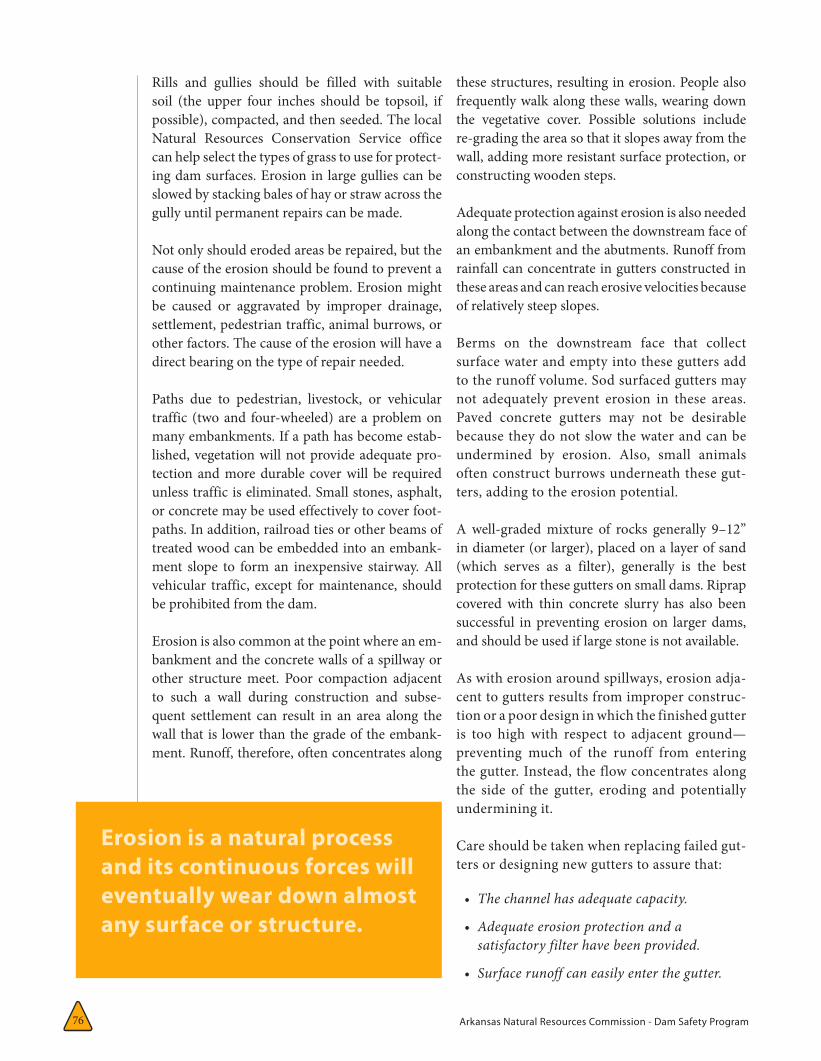
RIPRAP MAINTENANCE AND REPAIRA serious erosion problem called benching can develop on the upstream slope of a dam. Waves caused by high winds or high-speed boats can erode the exposed face of an embankment by repeatedly striking the surface just above the pool elevation, rushing up the slope, then tumbling back into the pool. This action erodes material from the face of the embankment and displaces it down the slope, creating a “bench.” Erosion of unprotected soil can be rapid and, during a severe storm, could lead to complete failure of a dam.
The upstream face of a dam is commonly protect-ed against wave erosion and resultant benching by placement on the face of a layer of rock riprap over a layer of filter material. Sometimes, materi-als such as bituminous or concrete facing, bricks, or concrete blocks are used for this upstream slope protection. Protective benches are sometimes actu-ally built into small dams by placing a berm (8–10 ft wide) along the upstream face a short distance below the normal pool level, supplying a surface on which wave energy can dissipate. Generally,
however, rock riprap offers the most economical and effective protection.
Nonetheless, benching can occur in exist-ing riprap if the embankment surface is not properly protected by a filter. Water running down the slope under the riprap can erode the embankment. Sections of riprap that have slumped downward are often signs of this kind of benching.
Similarly, concrete facing used to protect slopes may fail because waves wash soil from beneath the slabs through joints and cracks. Detection is difficult because the voids are hidden, and failure may be sudden and extensive. Effective slope protection must prevent soil from being removed from the embankment.
When erosion occurs and benching develops on the upstream slope of a dam (Figure 7.2), repairs should be made as soon as possible. Lower the pool level and prepare the surface of the dam for repair. Have a small berm built across the face of the dam at the base of the new layer of protection to help hold the layer in place. The size of the berm needed depends on the thick-ness of the protective layer.
FIGURE 7.2. BENCHING DUE TO WAVE EROSION OF UPSTREAM SLOPE OF DAM.
Arkansas Natural Resources Commission - Dam Safety Program78
slope, a spillway channel, a plunge pool, or, if erosion continues unchecked, the breaching of the embankment. The inspector should look closely for signs of soil erosion and undercut-ting in all riprap areas.
A dam owner should expect some riprap dete-rioration because of weathering. Freezing and thawing, wetting and drying, abrasive wave ac-tion and other natural processes will eventually break down the material. Therefore, allocate sufficient funds for the regular replacement of riprap. The useful life of riprap varies depending on the characteristics of the stone used. Thus, stone for riprap should be rock that is dense and well cemented. When riprap breaks down, and erosion and beaching occur more often than once every three to five years, professional ad-vice should be sought to design more effective slope protection.
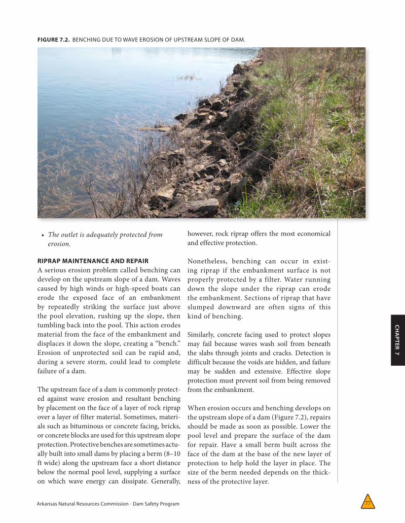
CONTROLLING VEGETATIONKeep the entire dam clear of unwanted vegeta-tion such as brush or trees. Excessive growth (Figure 7.3) may cause several problems:
• Itcanobscurethesurfaceofanembankmentandpreventathoroughinspectionofthedam.
• Largetreescanbeuprootedbyhighwindorerosionandleavelargeholesthatcanleadtobreachingofthedam.
• Somerootsystemscandecayandrot,creatingpassagewaysforwater,andthuscausingerosion.
• Growingrootsystemscanliftconcreteslabsorstructures.
• Trees,brush,andweedscanpreventthegrowthofdesirablegrasses.
• Rodenthabitatscandevelop.
When brush is cut down, it should be removed to permit a clear view of the embankment. Following removal of large brush and trees, extract their left-over root systems, fill and compact the resulting holes. In cases where trees and brush cannot be removed, the root systems should be treated with
A riprap layer should extend a minimum of 3 ft below the lowest expected normal pool level. Otherwise, wave action during periods of low lake level will undermine and destroy the pro-tection. If rock riprap is used, it should consist of a heterogeneous mixture of irregular shaped stone placed over a sand and gravel filter. The biggest rock must be large and heavy enough to break up the energy of the maximum expected waves and hold smaller stones in place. (An engineer may have to be consulted to determine the proper size.)
The smaller rocks help to fill the spaces between the larger pieces and to form a stable mass. The filter prevents soil particles on the embankment surface from being washed out through the spaces between the rocks in the riprap. If the filter material itself can be washed out through these voids and benching develops, two layers of filters may be required. The lower layer should be composed of sand or filter fabric to protect the soil surface and the upper layer should be composed of coarser materials.
When deficiencies prevent riprap from provid-ing erosion protection, the soil embankment beneath the riprap is exposed to erosion dam-age. Undercutting by wave action, slides, and slope failure can lead to failure of the upstream
FIGURE7.3. TREES AND WOODY BRUSH GROWING ON THE DAM.
Arkansas Natural Resources Commission - Dam Safety Program 79
CH
APTER 7
herbicide (properly selected and applied) to retard further growth. A licensed firm should be con-sulted regarding effective herbicides for control of vegetation on dam structures.
After the removal of brush, cuttings may need to be burned, in which case you should notify the local fire department, forest service, or other agencies responsible for fire control. If properly maintained, grass is not only an effective means of controlling erosion but also enhances the ap-pearance of a dam and provides a surface that can be easily inspected. Grass roots and stems tend to trap fine sand and soil particles, forming an erosion-resistant layer once the plants are well established. Grass is least effective in areas of concentrated runoff or in areas subjected to wave action.
CONTROLLING LIVESTOCKLivestock should not be allowed to graze on an embankment surface. When soil is wet, stock can damage vegetation and disrupt the unifor-mity of the surface. Moreover, livestock tend to walk in established paths and thus can promote severe erosion. Such paths should be re-graded and seeded, and the livestock permanently fenced out of the area.
CONTROLLING ANIMAL DAMAGEBurrowing animals (beaver, muskrat, ground-hogs, and others) are naturally attracted to the habitats created by dams and reservoirs and can endanger the structural integrity and proper performance of embankments and spillways. The burrows and tunnels of these animals gen-erally weaken earthen embankments and serve as pathways for seepage from the reservoir. This kind of damage has resulted in several failures of dams; therefore, controlling burrows is essential to their preservation.
Methods of repairing rodent damage depend upon the nature of the damage but, in any case, extermination of the rodent population is the required first step. If the damage consists mostly of shallow holes scattered across an embank-ment, repair may be necessary to maintain the appearance of the dam, to keep runoff waters
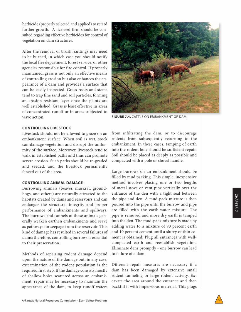
FIGURE 7.4. CATTLE ON EMBANKMENT OF DAM.
from infiltrating the dam, or to discourage rodents from subsequently returning to the embankment. In these cases, tamping of earth into the rodent hole should be sufficient repair. Soil should be placed as deeply as possible and compacted with a pole or shovel handle.
Large burrows on an embankment should be filled by mud packing. This simple, inexpensive method involves placing one or two lengths of metal stove or vent pipe vertically over the entrance of the den with a tight seal between the pipe and den. A mud-pack mixture is then poured into the pipe until the burrow and pipe are filled with the earth-water mixture. The pipe is removed and more dry earth is tamped into the den. The mud-pack mixture is made by adding water to a mixture of 90 percent earth and 10 percent cement until a slurry of thin ce-ment is obtained. Plug all entrances with well-compacted earth and reestablish vegetation. Eliminate dens promptly - one burrow can lead to failure of a dam.
Different repair measures are necessary if a dam has been damaged by extensive small rodent tunneling or large rodent activity. Ex-cavate the area around the entrance and then backfill it with impervious material. This plugs
Arkansas Natural Resources Commission - Dam Safety Program80
the passage entrance so that reservoir water is prevented from saturating the dam’s interior. This should be considered a temporary repair. Excavation and backfilling of the entire tunnel or filling of the tunnel with cement grout are possible long-term solutions, but pressure ce-ment grouting is an expensive and sometimes dangerous procedure. Indeed, pressure exerted during grouting can cause further damage to the embankment via hydraulic fracturing (an opening of cracks by high-pressure grouting). Thus, grouting should be performed only under the direction of an engineer.
CONTROLLING DAMAGE FROM TRAFFICAs mentioned earlier, vehicles driving across an embankment dam can create ruts in the crest if it is not surfaced with roadway material. The ruts can then collect water and cause saturation and softening of the dam. Other ruts may be formed by vehicles driving up and down a dam face; these can collect runoff and cause severe ero-sion. Vehicles, except for maintenance, should be banned from dam slopes and kept out by fences or barricades. Repair any ruts as soon as possible using the methods outlined in Section on Earthwork Maintenance and Repair. Main-tenance vehicles should only travel on the soil and grass portions of the dam when the surface is dry unless necessitated by an emergency.
MECHANICAL MAINTENANCEThe safe and satisfactory operation of a dam depends on proper operation of its outlet works. Release of water from a dam is normally a frequent or ongoing function. However, some reservoirs do not require the continual release of water. An operable outlet provides the only means for the emergency lowering of the reser-voir and is therefore essential for safety.
If routine inspection of the outlet works indi-cates the need for maintenance, the work should be completed as soon as access can be gained. Postponing maintenance could result in dam-age to the installation, significantly reduce the useful life of the structure, and result in more extensive and more costly repairs. More impor-tantly, failure to maintain an outlet system can
lead directly to dam failure.
The simplest procedure to ensure the smooth operation of outlet gates is to operate all gates through their full range at least once, and pref-erably twice, annually. In fact, many manufac-turers recommend operating gates as often as four times a year. Because operating gates under full reservoir pressure can result in large outlet discharges, schedule gate testing during periods of low storage, if possible, or else operate them during periods of low stream flow. If you expect large releases, only have the outlets tested after coordinating releases with the local floodplain administrator and other dam owners located downstream and after notifying downstream residents and water users.
Operation of the gates minimizes the buildup of rust in the operating mechanism and therefore the likelihood of its seizure. During this procedure:
• Checkthemechanicalpartsofthehoistingmechanism—includingdrivegears,bearings,andwearplates—foradverseorexcessivewear.
• Checkallbolts,includinganchorbolts,fortightness.
• Replacewornandcorrodedparts.
• Makemechanicalandalignmentadjustmentsasnecessary.
The way the gate actually operates should also be noted. Rough, noisy, or erratic movement could be the first signs of a developing problem. The causes of operational problems should be investigated and corrected immediately.
Excessive force should not be necessary to raise or lower a gate. Most hoisting mechanisms are de-signed to operate satisfactorily with a maximum force of 40 pounds on the operating handle or wheel. If excessive force seems necessary, some-thing may be binding the mechanical system. Excessive force may result in increased binding of the gate or damage to the outlet works. If there does seem to be undue resistance, the gate should be worked up and down repeatedly in short strokes

Arkansas Natural Resources Commission - Dam Safety Program 81
CH
APTER 7
until the binding ceases or the cause of the problem should be investigated. Of course, you should correct the problem as soon as possible to assure the contin-ued operability of the gate.
If a gate does not properly seal when closed, debris may be lodged under or around the gate leaf or frame. Raise the gate at least two to three inches to flush the debris; then have the operator attempt to reclose the gate. This procedure should be re-peated until proper sealing is achieved. However, if this problem or any other problem persists, con-sult a manufacturer’s representative or engineer experienced in gate design and operation.
An outlet gate’s operating mechanism should always be well-lubricated in accordance with the manufacturer’s specifications. Proper lubrication will not only reduce wear in the mechanism, but also protect it against adverse weather. Gates with oil-filled stems (i.e., stems encased in a larger sur-rounding pipe) should be checked twice each year to assure the proper oil level is maintained. If such mechanisms are neglected, water could enter the encasement pipe, which in turn could lead to the corrosion of both the gate stem and the interior of the encasement pipe.
The metal used in gate seats is usually brass, stain-less steel, bronze, or other rust resistant alloys. Older or smaller gates may not be fitted with seats, making them susceptible to rusting at the contact surfaces between the gate leaf and gate frame. Operation of gates should prevent excessive rust buildup or seizure.
For satisfactory operation, a gate stem must be maintained in proper alignment with the gate and hoisting mechanism. Proper alignment and support are supplied by stem guides in sufficient number and properly spaced along the stem. Stem guides are brackets or bearings through which a stem passes. They both prevent lateral movement of the stem and bending or buckling when a stem is subjected to compression as a gate is closing.
The alignment of a stem should be checked during routine inspections by sighting along the length of the stem, or more accurately by dropping a plumb
line from a point near the top of the stem to the other end. The stem should be checked in both an upstream–downstream direction as well as in a lateral direction to ensure straightness. While checking alignment, all gate stem guide anchors and adjusting bolts should be checked for tight-ness. A loose guide provides no support to the stem and could cause it to buckle at that point.
If, during normal inspection, the stem appears out of alignment, the cause should be remedied. Completely lower the gate and take all ten-
sion or compression off the stem. Loosen any misaligned stem guides and make them move freely. Then operate the hoisting mechanism so as to put tension on the stem, thereby straight-ening it, but do not open the gate. Then align and fasten the affected guides so that the stem passes exactly through their centers.
Many outlet gates are equipped with wedges that hold the gate leaf tightly against the gate frame as the gate is closed, thus ensuring a tight seal. Through years of use, gate seats may become worn, causing the gate to leak increasingly. If an installation has a wedge system, the leakage may be substantially reduced or eliminated by simply readjusting the wedges.
Because adjustment of these gates is com-plicated, inexperienced personnel can cause extensive damage. Improper adjustment could cause premature seating of the gate, possible scoring of the seats, binding, vibration, leakage, uneven closing, or damage to wedges or gate guides. Only experienced personnel should
Because adjustment of these gates is complicated, inexperienced personnel can cause extensive damage.
Arkansas Natural Resources Commission - Dam Safety Program82
perform adjustments. Consult a gate supplier or manufacturer to obtain names of persons experienced in such work.
Ice can exert great force on and cause significant damage to an outlet gate leaf. Storage levels in a reservoir during winter should be low enough that ice cannot form behind a gate. To prevent ice damage, the winter water level should be significantly higher than the gate if storage is maintained through the winter months, or, if the reservoir is to remain empty over the winter, the outlet should be fully open. If operations call for the water level to move across the gate during the winter, a bubbler or other anti-icing system may be needed.
ELECTRICAL MAINTENANCEElectricity is typically used at a dam for lighting and to operate outlet gates, spillway gates, record-ing equipment, and other miscellaneous equip-ment. It is important that an electrical system be well maintained, including a thorough check of fuses and a test of the system to ensure that all parts are properly functioning. The system should be free from moisture and dirt, and wiring should be checked for corrosion and mineral deposits. Carry out any necessary repairs immediately, and keep records of the work. Maintain generators used for auxiliary emergency power—change the oil, check the batteries and antifreeze and make sure fuel is readily available.
CLEANINGAs already suggested, the proper operation of spillways, sluiceways, approach channels, inlet and outlet structures, stilling basins, discharge conduit, dam slopes, trash racks, and debris-control devices require regular and thorough cleaning and removal of debris. Cleaning is es-pecially important after upstream storms, which tend to send more debris into the reservoir.
CONCRETE MAINTENANCEAlso as mentioned, periodic maintenance should be performed on all concrete surfaces to repair deteriorated areas. Repair deteriorated concrete immediately when noted; it is most easily repaired in its early stages. Deterioration
can accelerate and, if left unattended, can result in serious problems or dam failure. Consult an experienced engineer to determine both the ex-tent of deterioration and the proper method of repair. Seal joints and cracks in concrete struc-tures to avoid damage beneath the concrete.
METAL COMPONENT MAINTENANCEAll exposed, bare ferrous metal on an outlet installation, whether submerged or exposed to air, will tend to rust. To prevent corrosion, exposed ferrous metals must be either appro-priately painted (following the paint manufac-turer’s directions) or heavily greased. When areas are repainted, ensure that paint does not get on gate seats, wedges, or stems (where they pass through the stem guides), or on other fric-tion surfaces where paint could cause binding. Use heavy grease on surfaces where binding can occur. Because rust is especially damaging to contact surfaces, remove existing rust before the periodic application of grease.
Arkansas Natural Resources Commission - Dam Safety Program 83
CH
APTER 7
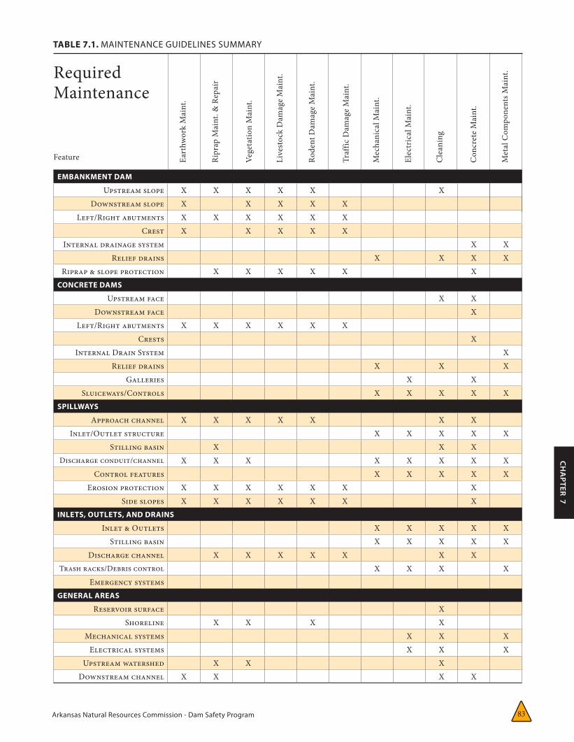
EMBANKMENT DAM
Upstream slope X X X X X XDownstream slope X X X X X
Left/Right abutments X X X X X XCrest X X X X X
Internal drainage system X XRelief drains X X X X
Riprap & slope protection X X X X X XCONCRETE DAMS
Upstream face X XDownstream face X
Left/Right abutments X X X X X XCrests X
Internal Drain System XRelief drains X X X
Galleries X XSluiceways/Controls X X X X X
SPILLWAYS
Approach channel X X X X X X XInlet/Outlet structure X X X X X
Stilling basin X X XDischarge conduit/channel X X X X X X X X
Control features X X X X XErosion protection X X X X X X X
Side slopes X X X X X X XINLETS, OUTLETS, AND DRAINS
Inlet & Outlets X X X X XStilling basin X X X X X
Discharge channel X X X X X X XTrash racks/Debris control X X X X
Emergency systemsGENERAL AREAS
Reservoir surface XShoreline X X X X
Mechanical systems X X XElectrical systems X X X
Upstream watershed X X XDownstream channel X X X X
RequiredMaintenance
TABLE 7.1. MAINTENANCE GUIDELINES SUMMARY
Eart
hwor
k M
aint
.
Vege
tatio
n M
aint
.
Ripr
ap M
aint
. & R
epai
r
Live
stoc
k D
amag
e M
aint
.
Rode
nt D
amag
e M
aint
.
Traf
fic D
amag
e M
aint
.
Mec
hani
cal M
aint
.
Elec
tric
al M
aint
.
Cle
anin
g
Con
cret
e M
aint
.
Feature Met
al C
ompo
nent
s Mai
nt.
Arkansas Natural Resources Commission - Dam Safety Program 84
CH
APTER 8
General
The primary goal of the state’s dam safety program is to reduce the risk to lives and property from the con-sequences of dam failure. Although most dam owners have a high level of confidence in the structures they own and are certain their dams will not fail. History has shown however, that, on occasion, dams do fail
and that often these failures cause extensive property damage and sometimes death. A dam owner is responsible for keeping these threats to a minimum. A carefully conceived and implemented Emergency Action Plan (EAP) is one positive step you, the dam owner, can take to accomplish dam safety objectives, protect your investment and reduce potential liability.
CHAPTER 8:
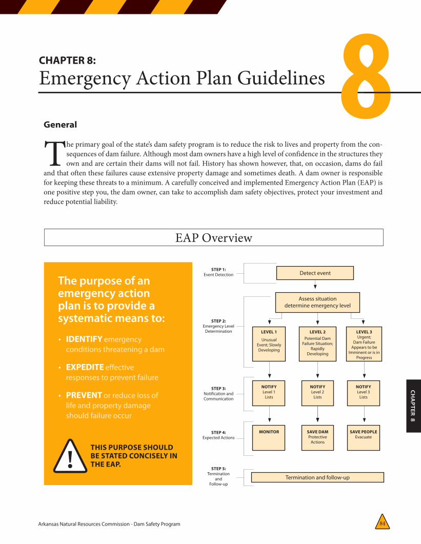
Emergency Action Plan Guidelines8The purpose of an emergency action plan is to provide a systematic means to:
THIS PURPOSE SHOULD BE STATED CONCISELY INTHE EAP.
• IDENTIFY emergency conditions threatening a dam
• EXPEDITE effective responses to prevent failure
• PREVENT or reduce loss of life and property damage should failure occur
!
Detect event
EAP Overview
Termination and follow-up
Assess situationdetermine emergency level
LEVEL 1
Unusual Event; Slowly Developing
STEP 1:Event Detection
STEP 2:Emergency Level
Determination
STEP 3:Notification and Communication
STEP 4:Expected Actions
STEP 5:Termination
andFollow-up
NOTIFYLevel 1
Lists
MONITOR
NOTIFYLevel 2
Lists
SAVE DAMProtective
Actions
NOTIFYLevel 3
Lists
SAVE PEOPLEEvacuate
LEVEL 2Potential Dam
Failure Situation; Rapidly
Developing
LEVEL 3Urgent;
Dam Failure Appears to be
Imminent or is in Progress
Arkansas Natural Resources Commission - Dam Safety Program85
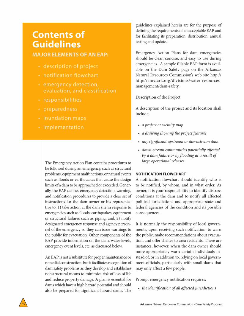
Contents of GuidelinesMAJOR ELEMENTS OF AN EAP:
• descriptionofproject
• notificationflowchart
• emergencydetection,evaluation,andclassification
• responsibilities
• preparedness
• inundationmaps
• implementation
The Emergency Action Plan contains procedures to be followed during an emergency, such as structural problems, equipment malfunctions, or natural events such as floods or earthquakes that cause the design limits of a dam to be approached or exceeded. Gener-ally, the EAP defines emergency detection, warning, and notification procedures to provide a clear set of instructions for the dam owner or his representa-tive to: 1) take action at the dam site in response to emergencies such as floods, earthquakes, equipment or structural failures such as piping; and, 2) notify designated emergency response and agency person-nel of the emergency so they can issue warnings to the public for evacuation. Other components of the EAP provide information on the dam, water levels, emergency event levels, etc. as discussed below.
An EAP is not a substitute for proper maintenance or remedial construction, but it facilitates recognition of dam safety problems as they develop and establishes nonstructural means to minimize risk of loss of life and reduce property damage. A plan is essential for dams which have a high hazard potential and should also be prepared for significant hazard dams. The
guidelines explained herein are for the purpose of defining the requirements of an acceptable EAP and for facilitating its preparation, distribution, annual testing and update.
Emergency Action Plans for dam emergencies should be clear, concise, and easy to use during emergencies. A sample fillable EAP form is avail-able on the Dam Safety page on the Arkansas Natural Resources Commission’s web site http://http://anrc.ark.org/divisions/water-resources-management/dam-safety..
Description of the Project
A description of the project and its location shall include:
• aprojectorvicinitymap
• adrawingshowingtheprojectfeatures
• anysignificantupstreamordownstreamdam
• down-streamcommunitiespotentiallyaffectedbyadamfailureorbyfloodingasaresultoflargeoperationalreleases
NOTIFICATION FLOWCHARTA notification flowchart should identify who is to be notified, by whom, and in what order. As owner, it is your responsibility to identify distress conditions at the dam and to notify all affected political jurisdictions and appropriate state and federal agencies of the condition and its possible consequences.
It is normally the responsibility of local govern-ments, upon receiving such notification, to warn the public, make recommendations about evacua-tion, and offer shelter to area residents. There are instances, however, when the dam owner should more appropriately warn certain individuals in-stead of, or in addition to, relying on local govern-ment officials, particularly with small dams that may only affect a few people.
Prompt emergency notification requires:
• theidentificationofallaffectedjurisdictions
Arkansas Natural Resources Commission - Dam Safety Program 86
CH
APTER 8
• thedevelopmentandannual(ormorefrequent)updatingofnames,telephonenumbersofindividualsandagenciestocontact;and
• thedevelopmentofprimaryandalternateproceduresfornotificationorwarningregardlessoftimeofday,dayoftheweek,orweather
When developing the notification flowchart, call the appropriate parties to determine the contacts and phone numbers for key emergency person-nel. In the event that an emergency condition is declared at a dam, you, the owner, or the operator will initiate emergency notification.
The notification element of an EAP should be brief, simple, and easy to implement under any conditions. Use the appropriate emergency level (1, 2 or 3) noti-fication message when contacting key officials about an emergency condition at a dam.
EMERGENCY DETECTION, EVALUATION, AND CLASSIFICATIONSThe EAP should indicate procedures for timely and reliable detection, evaluation, and classi-fication of an existing or potential emergency situation. It should list the conditions, events, or measures for detection of an existing or potential emergency. The EAP should also in-corporate an assessment of the dam, including its vulnerability to all appropriate known emer-gency conditions such as severe thunderstorms with lightning and excessive rains, hurricanes, tornadoes, earthquakes, etc., as well as a listing and explanation of problem indicators.
As owner, you are responsible for regularly moni-toring the condition of your dam and correcting any deficiencies. The plan must include a routine inspection schedule and name the person or position responsible for the inspection; it should emphasize indicators of the onset of problems that might cause failure of the dam:
• slumping,sloughing,orslidesonthedamortheabutment
• cloudyordirtyseepageorseepagewithan
increaseinflow,boils,piping,orbogs
• seepagearoundconduits
• cracks,settlement,misalignment,orsinkholes
• erosionorriprapdisplacement
• animalburrows,especiallythoseassociatedwithbeaversornutria
• growthoftreesandbrush
• failureofoperatingequipment
• abnormalinstrumentationreadings
• leakageofwaterintotheintaketower
• underminingofspillways
• overtoppingofthedam
The plan must address what action to take and what resources will be used when one of these in-dicators is observed and how quickly you or your responsible agent is to report the problem.
Keep records relating to any of the indicators listed above to determine if changes are occur-ring. This will permit an intelligent assessment of the problems and the proper implementation of the emergency action plan. However, if you determine that failure is at all possible, report the situation immediately to the local emer-gency management officials, Arkansas Natural Resources Commission, Dam Safety Program, and immediately implement all applicable noti-fication procedures and emergency actions.
RESPONSIBILITIESThe EAP is to identify:
• whoisresponsibleforaccomplishingeachoftherequiredemergencyactionssoastomeetallplanrequirements;
• whoisinchargeofemergencyresponseactions;
• communicationandcoordinationchannels;
• thelocationofthecommandpost,controlroom,oremergencyoperatingcenter;and
• linesofsuccessionandassumptionsofresponsibilitynecessarytoensure
Arkansas Natural Resources Commission - Dam Safety Program87
uninterrupted emergency-response actions under any conditions.
PreparednessThe EAP should identify ways of preparing for an emergency, of increasing response readiness in a uniform and coordinated manner, and helping to reduce the effects of a dam failure. The goal is maximum readiness to respond in a minimum amount of time.
Categorize potential emergencies into phases or conditions and identify specific actions to reduce the possibility of either under reacting or overre-acting to a given situation. List anticipated failure situations and appropriate responses, such as:
EMERGENCY WATER RELEASEThe release of water at the dam to lower lake levels is a normal procedure. An emergency release (i.e., in excess of normal) could flood certain down-stream areas.
WATCH CONDITIONA problem has been detected at the dam which re-quires constant monitoring or immediate action to repair or correct. At this time, the distress condition is manageable by dam personnel. A watch condition will continue until the problem is corrected, or a pos-sible dam-failure warning is issued.
POSSIBLE-DAM-FAILURE WARNINGA condition that is progressively getting worse. Efforts to correct the situation will continue but a possibility now exists that the dam could fail if these efforts are unsuccessful. There is no imme-diate danger; however, if conditions continue to deteriorate, the dam could fail.
IMMINENT-DAM-FAILURE WARNINGYou (the owner) or the operator has determined that conditions will progress to failure of the dam and an uncontrollable release of the reservoir. The dam will most likely fail regardless of what imme-diate measures are taken.
DAM FAILURE
The dam has failed and a flood wave is now mov-ing downstream. Flooding will start immediately and will continue to move downstream until water levels at the reservoir are stabilized. Massive de-struction can be expected from the flood wave and evacuation of downstream areas should continue in accordance with local plans.
The EAP should also identify:
• supportcapabilities,suchaspersonnelororganizationsthatcanprovideassistanceandtheproceduresforcontactingthem;
• theexistenceandlocationofsuppliesandequipmentavailableforuseinremedialactions;
• proceduresforemergencypurchaseorprocurementofsuppliesandequipmentneededforremedialactions;and
• remedialconstructionandotheractivitiestopreventafailureofthedam.
Inundation MapsInundation maps showing potential areas of flood-ing from a dam failure are essential in local warn-ing and evacuation planning and must be included with the emergency action plan. The inundation maps shall delineate areas that would be flooded as a result of a dam failure and should include the time to flood (the time from the breach to the time that critical structures are flooded) and the time to peak flow. See ANRC Guidelines for Dam Breach Inundation Mapping in Arkansas for more detailed information on this topic.
IMPLEMENTATIONAfter completing the plan, take steps to implement it. Supply copies of the completed plan to the Ar-kansas Natural Resources Commission and other appropriate officials. The local National Weather Service office should receive a copy of the inun-dation maps to allow development of customized watch and warning messages. The owner should schedule briefings with local officials to facilitate the incorporation of planning information into local government emergency management plans.
Arkansas Natural Resources Commission - Dam Safety Program 88
CH
APTER 8
Ove
rtop
ping
Emba
nkm
ent S
lides
Erod
ing
Flow
s
Wav
e Er
osio
n
Out
let F
ailu
re
Mas
s Slid
ing
Emba
nkm
ent S
atur
atio
n
Spill
way
Bac
kcut
ting
Emba
nkm
ent S
ettle
men
t
Loss
of A
butm
ent
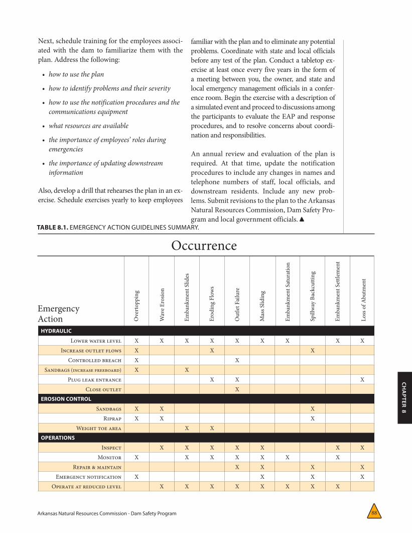
HYDRAULIC
Lower water level X X X X X X X X XIncrease outlet flows X X X
Controlled breach X XSandbags (increase freeboard) X X
Plug leak entrance X X XClose outlet X
EROSION CONTROL
Sandbags X X XRiprap X X X
Weight toe area X XOPERATIONS
Inspect X X X X X X XMonitor X X X X X X X
Repair & maintain X X X XEmergency notification X X X X
Operate at reduced level X X X X X X X X
TABLE 8.1. EMERGENCY ACTION GUIDELINES SUMMARY.
EmergencyAction
Occurrence
Next, schedule training for the employees associ-ated with the dam to familiarize them with the plan. Address the following:
• howtousetheplan
• howtoidentifyproblemsandtheirseverity
• howtousethenotificationproceduresandthecommunicationsequipment
• whatresourcesareavailable
• theimportanceofemployees’rolesduringemergencies
• theimportanceofupdatingdownstreaminformation
Also, develop a drill that rehearses the plan in an ex-ercise. Schedule exercises yearly to keep employees
familiar with the plan and to eliminate any potential problems. Coordinate with state and local officials before any test of the plan. Conduct a tabletop ex-ercise at least once every five years in the form of a meeting between you, the owner, and state and local emergency management officials in a confer-ence room. Begin the exercise with a description of a simulated event and proceed to discussions among the participants to evaluate the EAP and response procedures, and to resolve concerns about coordi-nation and responsibilities.
An annual review and evaluation of the plan is required. At that time, update the notification procedures to include any changes in names and telephone numbers of staff, local officials, and downstream residents. Include any new prob-lems. Submit revisions to the plan to the Arkansas Natural Resources Commission, Dam Safety Pro-gram and local government officials.
Arkansas Natural Resources Commission - Dam Safety Program 89
CH
APTER 9
CHAPTER 9:
Guidelines for Operations
• maintenanceguidelines(Chapter7)
• guidelinesforemergencyoperations (Chapter8)
• bibliographicalinformation(Bibliography)
As recommended in Chapter 4, collection and review of existing information on the dam’s de-sign, construction, and structural characteristics comprise the first step in developing a dam safety program. Guidelines for inspections, monitoring, maintenance, and emergency action planning ap-pear in the other chapters as indicated.
The operation plan should have several separate sections:
A. Background Data
1. Vital dam statistics
2. Description of appurtenances
B. Operating Instructions and Records
1. Operating instructions for operable mechanisms
2. Inspection instructions and forms
3. Monitoring instructions and forms
4. Maintenance instructions and forms
5. Bibliography
6. Telephone list
C. Emergency Action Plan
9General
An operation plan details each of the safety-program components outlined in Chapter 4 and detailed in Chapters 5 through 8.
The extent of an operation plan depends on the complexity of the dam itself—factors such as dam size, the number and type of appurtenances, and operating mechanisms. The operation of a dam may involve adjusting the reservoir level, controlling debris by opening and closing valves, keeping records, and, in general, ensuring public safety. Proper operation procedures are extremely important for maintaining a safe structure. Many small dams do not need a full-time operator, but should be checked regularly. Special operational procedures to be followed during an emergency should be posted, particularly if the owner/opera-tor is not always available.
Plan GuidelinesEstablishing an operations procedure or plan calls for detailed documentation of the following:
• dataonthephysicalcharacteristicsofdamandreservoir
• descriptionsofdamcomponents(Chapter2)
• operationsinstructionsforoperablemechanisms(Chapter9)
• inspectionguidelines(Chapter5)
• instrumentationandmonitoringguidelines(Chapter6)
Arkansas Natural Resources Commission - Dam Safety Program90
Sections A and B are described briefly below and a schedule of routine tasks is included. Instructions are included for frequent inspections, monitoring, and follow-up maintenance. The emergency ac-tion plan is discussed in Chapter 8.
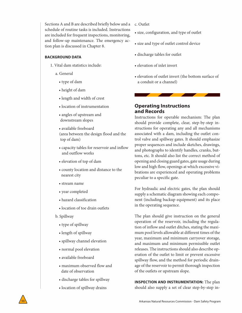
BACKGROUND DATA
1. Vital dam statistics include:
a. General
•typeofdam
•heightofdam
•lengthandwidthofcrest
•locationofinstrumentation
•anglesofupstreamand downstream slopes
•availablefreeboard (area between the design flood and the top of dam)
•capacitytablesforreservoirandinflow and outflow works
•elevationoftopofdam
•countylocationanddistancetothe nearest city
•streamname
•yearcompleted
•hazardclassification
•locationoftoedrainoutlets
b. Spillway
•typeofspillway
•lengthofspillway
•spillwaychannelelevation
•normalpoolelevation
•availablefreeboard
•maximumobservedflowand date of observation
•dischargetablesforspillway
•locationofspillwaydrains
c. Outlet
•size,configuration,andtypeofoutlet
•sizeandtypeofoutletcontroldevice
•dischargetablesforoutlet
•elevationofinletinvert
•elevationofoutletinvert(thebottomsurfaceof a conduit or a channel)
Operating Instructions and RecordsInstructions for operable mechanism: The plan should provide complete, clear, step-by-step in-structions for operating any and all mechanisms associated with a dam, including the outlet con-trolvalveandspillwaygates.Itshouldemphasizeproper sequences and include sketches, drawings, and photographs to identify handles, cranks, but-tons, etc. It should also list the correct method of opening and closing guard gates, gate usage during lowandhighflow,openingsatwhichexcessivevi-brationsareexperiencedandoperatingproblemspeculiar to a specific gate.
For hydraulic and electric gates, the plan should supply a schematic diagram showing each compo-nent (including backup equipment) and its place in the operating sequence.
Theplan should give instructionon the generaloperation of the reservoir, including the regula-tionofinflowandoutletditches,statingthemaxi-mumpoollevelsallowableatdifferenttimesoftheyear,maximumandminimumcarryoverstorage,andmaximumandminimumpermissibleoutletreleases. The instructions should also describe op-erationoftheoutlettolimitorpreventexcessivespillway flow, and the method for periodic drain-ageofthereservoirtopermitthoroughinspectionof the outlets or upstream slope.
INSPECTION AND INSTRUMENTATION: The plan should also supply a set of clear step-by-step in-
Arkansas Natural Resources Commission - Dam Safety Program 91
CH
APTER 9
structions for a comprehensive inspection of the dam and its surroundings, record data on forms like those in the Appendixes, and keep copies of all completed inspection records and photographs.
MONITORING INSTRUCTIONS: Prepare clear in-structions on how to use monitoring instruments and how to take measurements at monitoring points; include a map identifying each instrument and monitoring point and forms for recording the data. Keep the monitoring points themselves, plus any seepage or other areas needing special attention, clear of obscuring growth. The points should be clearly and permanently marked so they can be eas-ily found during inspection. The help of a qualified engineer will be useful in developing this section.
Monitoring can only be beneficial if the observa-tions are recorded in an orderly way and form a clear record of performance. Thus, plotting or charting some of the readings will be necessary. The plan should give instructions on how to make and record each measurement or observation.
If your own engineer is not going to plot or chart the data, develop instructions and forms to allow yourself, an operator, or maintenance personnel to do this work. An experienced consulting engineer may be helpful in preparing the needed formats.
Maintenance instructions: The plan should give instructions for periodic maintenance in detail, so that new personnel can understand the task and experienced personnel can verify that they have completed the work properly. See Table 9.1 for a schedule of routine tasks. List all needed maintenance work. Include the tasks described in Chapter 7, such as:
• removingbrushandtrees
• removingdebris
• mowingandtrimming
• re-gradingthecrestandaccessroads
• removingharmfulrodents
• operatingandlubricatinggates
• addingriprapwhenneeded
• sealingjointsinconcretefacings
• cleaningdrainpipesandoutlets
• maintainingmonitoringpoints
• maintainingthesecurityofoperatingequipment
BIBLIOGRAPHY: The plan should catalog all avail-able reference material in a single list. Include the title, the author or agency responsible for publica-tion, the date and place of publication, and the permanent location of the material (for example, filing cabinet in basement) for each resource.
Even materials without titles or authors, such as photographs and maintenance information, should be listed.
TELEPHONE LIST: A comprehensive up-to-date listing of important telephone numbers should be maintained and include numbers for:
• theowner’sandoperator’shome,office,mobile,pager,andanyotherphones
• employeesactivelyinvolvedwiththedam
• thelocalemergencymanagementagency
• ARDeptofEmergencyManagement
• localpoliceandfiredepartments
• theArkansasNaturalResourcesCommission,DamSafetyProgram
• qualifiedlocalengineeringconsultants
• downstreamresidents
• acontractorwithaccesstoadequateequipmentandmaterial
Schedule of Routine TasksEstablish a schedule that includes both day-to-day tasks and tasks performed less frequently during the year. Such a schedule serves to formalize in-spection and maintenance procedures and makes it easy to determine when a task should be done. As suggested in Table 9.1, the frequency of a re-
Arkansas Natural Resources Commission - Dam Safety Program92
HAZARD-POTENTIAL CLASSIFICATION
Frequency (minimum) High Hazard-Potential Significant Hazard-Potential Low Hazard-Potential
Daily Surveillance None NoneWeekly Monitor seepage Surveillance None
Monthly Collect & examine observation well or other data.
Collect & examine observations well data
Surveillance. Monitor seepageCollect & examine observation data
Quarterly Inspect visually Inspect visually None
Biannually Test outlet & spillway components. None None
AnnuallyInspection by engineer.
Check alignments & movements.
Inspection by engineer.
Test outlet & spillway components.
Check alignments & movements.
Visual inspection.
Test outlet.
As Required Routine maintenance & additional inspections.
Routine maintenance & additional inspections.
Routine maintenance & additional inspections.
Check alignments & movements.
Immediately After Floods & Earthquakes Additional inspections Additional inspections Additional inspections
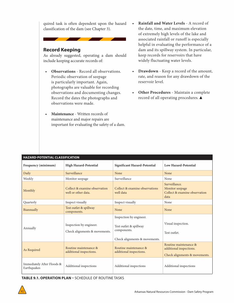
TABLE 9.1. OPERATION PLAN – SCHEDULE OF ROUTINE TASKS
quired task is often dependent upon the hazard classification of the dam (see Chapter 3).
Record KeepingAs already suggested, operating a dam should include keeping accurate records of:
• Observations - Record all observations. Periodic observation of seepage is particularly important. Again, photographs are valuable for recording observations and documenting changes. Record the dates the photographs and observations were made.
• Maintenance - Written records of maintenance and major repairs are important for evaluating the safety of a dam.
• Rainfall and Water Levels - A record of the date, time, and maximum elevation of extremely high levels of the lake and associated rainfall or runoff is especially helpful in evaluating the performance of a dam and its spillway system. In particular, keep records for reservoirs that have widely fluctuating water levels.
• Drawdown - Keep a record of the amount, rate, and reason for any drawdown of the reservoir level.
• Other Procedures - Maintain a complete record of all operating procedures.
Arkansas Natural Resources Commission - Dam Safety Program 93
CH
APTER 10
CHAPTER 10:
Reducing the Consequences of Dam Failure 10
Supplements to a Dam Safety Program
This manual has stressed safety as both a fundamental need and a prime respon-sibility of the dam owner. Developing an
effective dam safety program is the single most important measure you, the owner, can take to reduce the possibility or consequences of dam failure. The current level of dam safety is still far from acceptable. As construction continues to expand into rural areas more and more habitable structures are being built within a dam’s potential inundation area increasing the dam’s hazard clas-sification. This is a potentially dangerous practice that also creates significant costs and problems for a dam owner.
Liabilities that arise following a dam failure strongly affect organizations and people, governments and dam owners. Determination of liability is the legal means developed by society to recover damages due to a wrong (in this case, lack of dam safety). A
thorough understanding of this legal process can help you decide on measures to reduce liability. A discussion of liability and its relation to a dam owner is presented below, followed by a discussion of three important measures beyond that of individual dam safety that dam owners can promote to reduce li-ability: the use of insurance, the provision of govern-mental assistance, and the use of consultants.
LiabilityThe following discussion reviews general prin-ciples concerning liability and the operation of reservoirs. Liability in specific instances, however, is highly dependent upon the nature and con-struction of the dam, the particular circumstances surrounding the accident, the owner’s action or failure to act, and the jurisdiction in which the reservoir is located. In the event of a dam failure, the most commonly used theories to be pursued in litigation are negligence and strict liability.
The liability of an owner of a reservoir is con-sidered general civil (“tort”) liability. A tort is simply a civil wrong for which an injured party may recover damages from the responsible party. In most circumstances, simply causing damage is not a sufficient basis for the imposition of li-ability. Negligence must accompany the injury before liability is incurred. However, negligence is not a fixed concept; it has been modified and changed by court decisions over the years.
Developing an effective dam safety program is the single most important measure you, the owner, can take to reduce the possibility or consequences of dam failure.
Arkansas Natural Resources Commission - Dam Safety Program94
In simplest terms, it has been described as the violation of a duty to act as a reasonable and prudent person would act; a violation which directly results in damage to another.
The questions of what duty is imposed by soci-ety and what standard of reasonable care is im-posed by that duty have undergone enormous
scrutiny and changes over the past 40 years. In many instances the duty to make a product safe or the duty to ensure that one’s property does not pose a danger to others has significantly increased.
While the concept of negligence has substantially broadened, changes in the limits of negligence do not directly affect dam owners in those jurisdic-tions where a separate basis of liability has long been imposed upon them. This standard, “strict liability,” is based not on fault or negligence, but solely upon resulting damage, regardless of fault. Strict liability is generally applied to activities deemed extremely hazardous and not capable of being rendered reasonably safe.
The whole concept of strict liability was first es-tablished in a case involving a reservoir—the 1866 English case Fletcher v. Rylands, L.R. 1, Ex. 265. A reservoir was built in the vicinity of abandoned coal mines; the water from the reservoir found its way into the abandoned shafts and from there
into active shafts, causing damage. Under pres-ent legal thought, the basis of liability for such an occurrence may well be negligent design (i.e., failure to adequately investigate the surrounding circumstances at the time the reservoir was built). However, the actual decision assumed that no one could have known the abandoned mine shafts ex-isted and specifically determined that the owner was not negligent.
Nonetheless, the English court established the concept of strict liability for reservoir owners, and the owner of the reservoir was found liable for the escape of water from the reservoir, regard-less of fault. The holding in Fletcher v. Rylands has subsequently been adopted by many, but not all, U.S. courts and has been cited when similar circumstances are considered. It is the basis for imposing liability on the owner of a reservoir for all damages caused, regardless of fault and without a need to prove negligence.
Thus, with a very limited number of exceptions, the general principle regarding liability for the owner or operator of a reservoir (in a jurisdiction which recognizes strict liability) is:
“If water escapes from a dam, regardless of fault, the owner is responsible for all damages sustained.”
Note, however, that all of the discussion concern-ing compensation for damages due to release of water from a reservoir deal solely with water that has previously been stored. In all circumstances to date, and in most states by specific statute, a dam owner may pass on all natural flood waters without incurring any liability downstream.
Strict liability has two relatively narrow exceptions: acts of God and intentional acts of third parties over whom the owner had no control. While acts of God are recognized as a defense, they do not in-clude all natural occurrences over which the owner had no control, but are more narrowly limited to over which the owner had no control and could not have anticipated using available expertise. The other exception—intentional acts of third parties—was established by the Wyoming Supreme Court in the Wheatland case [Wheatland Irrigation District
“If water escapes from a dam, regardless of fault, the owner is responsible for all damages sustained.”
Arkansas Natural Resources Commission - Dam Safety Program 95
CH
APTER 10
v. McGuire, 537P.2d 1128 (1975)].
An irrigation district asserted that its reservoir had been damaged by saboteurs, and the Wyoming Supreme Court recognized that illegal, intentional acts by third parties which the owner could not protect against or anticipate were a viable defense to strict liability.
Still, where there is no remedial legislation, the circumstances in which the reservoir owner is not liable for all damages caused by the leaking or breaking of a dam are severely limited.
While the standard of strict liability imposed on a reservoir owner affords extremely limited relief, sev-eral states have enacted legislation that limits liability for damages in many instances. In many other states, by statute or under common law, the owner of a res-ervoir is entitled to release water to the “normal high water line” of a stream without incurring liability for property damaged within the “normal” flood area. However, the definition of the limits within which no liability is imposed varies from place to place and may not be clearly designated on maps. Nonetheless, the right to release water to defined or “historic” floodplain regions downstream from a reservoir can provide substantial relief from strict liability for a reservoir owner.
Statutory modification of the basis of a reservoir owner’s liability, as passed in some states, could have a significant effect. However, as noted above, the trend during the past 25 years has been to widen, not narrow, the scope of negligent behavior by imposing broad expectations of prudence and foresight. Even if standards of “strict liability” are replaced by standards of “negligence,” in the case of a reservoir owner, because the criteria of reason-able care and foresight are broadly interpreted, the change may not greatly affect the actual outcome.
In summary, existing law holds a reservoir owner to the highest standard of care. The owner may be held liable for all damages caused by water escaping from a reservoir—despite the best efforts of the owner
and regardless of when downstream development occurred relative to the date of completion.
Measures to Reduce the Consequences of Dam FailuresYou, the owner, can directly and indirectly in-fluence the introduction and use of a variety of measures that will reduce the consequences of dam failure. You should buy insurance, thus pool-ing your individual risk with others’. Land-use measures, although difficult to institute, can be an even better means of mitigating future disasters. (Restricting people from living in inundation zones obviously will radically improve safety.) In-creasing public awareness and better governmen-tal planning also can reduce the consequences of dam failure.
A dam owner can and should obtain insurance di-rectly. The other measures discussed here, land use, public awareness and preparedness planning, are es-sentially controlled by local governments. Therefore, you would be wise to encourage, as strongly as pos-sible, awareness and action within the public sector.
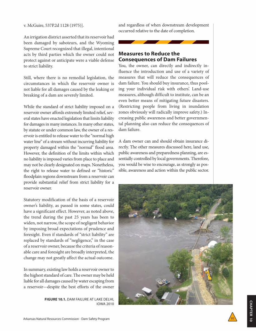
FIGURE 10.1. DAM FAILURE AT LAKE DELHI, IOWA 2010
Arkansas Natural Resources Commission - Dam Safety Program96
Finally, you may also wish to hire consultants from the private sector when the information needed for prudent decisions exceeds your expertise.
INSURANCEIn many states a minimum level of insurance cov-erage is mandated by law. In Arkansas, insurance is voluntary. In either case, the level of insurance you carry should be based on state law, the value of facilities at risk, potential downstream impacts, the condition and age of the dam, the likelihood of a claim and the cost of available insurance. Be-cause insurance spreads risk among a large group of people, it can not only protect you or your or-ganization, but also your employees and members of governing boards who may be held personally liable. Types of coverage, availability, and cost will vary from time to time; you would do well to seek professional advice when purchasing insurance. Some insurance companies and brokers specialize in issues related to dam failure.
Industry representatives can recommend insurers. A policy can cover not only damage and liability, but also the cost of business interruption, lost income, and workers’ compensation.
Insurance should be considered an accepted cost of doing business or enjoying the amenities a dam provides. Many have avoided this cost and have paid severely for their shortsightedness.
GOVERNMENT ASSISTANCEA fundamental function of government is to protect citizens from threats to their health, safety, and general welfare. Reducing the con-sequences of dam failure is clearly a duty of fed-eral, state, and local governments, which have joint and separate responsibilities to the public concerning dam safety.
Land-use planning, public-awareness programs, and emergency-preparedness planning are typi-cally conducted locally, usually the city or county. Federal agencies have technical expertise and can normally supply technical assistance when requested, but ultimately each state is responsible for its own dam-safety program.
Local-government roles – settlement pattern and population growth strongly affect the costs of dam failures. More simply, if no one were al-lowed to settle in hazardous areas, few, if any, lives would be lost and little property damaged. Conversely, as settlement continues near dams and in inundation zones, the potential for di-saster increases commensurately. “Low hazard” dams are continually being transformed into “significant-hazard” and “high-hazard” dams as this settlement continues. Increased losses are inevitable unless significant land-use measures are enacted to restrict the use of land in inun-dation zones. The strategies used will reflect federal, state, and local efforts, but local gov-ernment must make the critical decisions and only rely on state and federal government for support. All elements of mitigation planning are based on, or affected by, the way in which the affected land is used.
If the land has not been developed, the establish-ment of open space areas in potential inundation zones is a particularly effective, indeed, the best way, to reduce future costs of dam failure. None-theless, few states have organized programs or strategies of land acquisition or settlement restric-tion, usually because of strong opposition among developers and landowners.
If land is already under development, zoning measures to limit high population density can be useful. Also, the establishment of “green areas,” parks or golf courses, can be low-cost means of limiting settlement in inundation zones. In some fully developed areas, flood proofing devices (walls, barriers) may prove useful, but must also be maintained.
In much of the nation’s inundation zones, land has already been developed and housing is already in place. People who live in such areas may have a false sense of security, unaware that a hazard even exists.
Experience has clearly shown that simple warn-ing and evacuation procedures can save a signif-icant number of lives. Table 10.1 demonstrates this success and the corresponding failure when
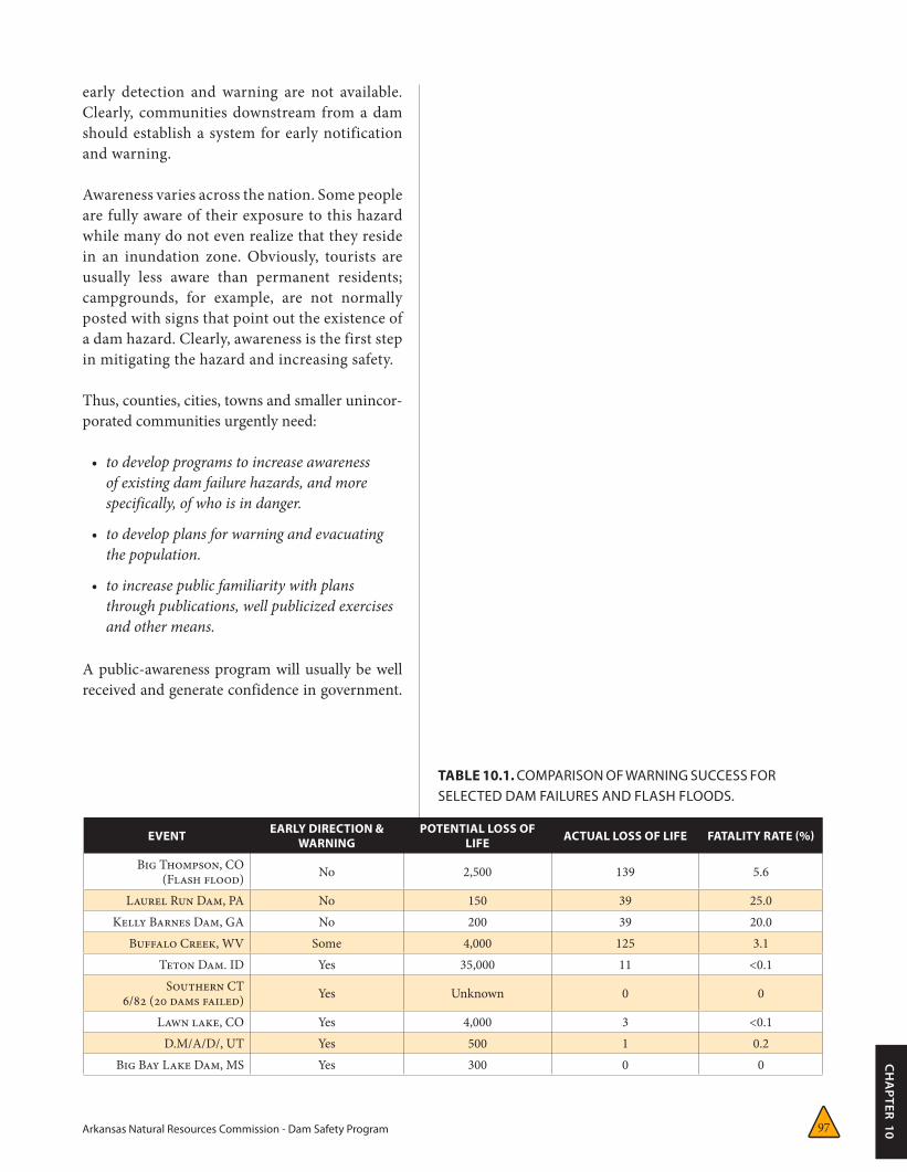
Arkansas Natural Resources Commission - Dam Safety Program 97
CH
APTER 10
TABLE 10.1. COMPARISON OF WARNING SUCCESS FOR SELECTED DAM FAILURES AND FLASH FLOODS.
EVENT EARLY DIRECTION & WARNING
POTENTIAL LOSS OF LIFE ACTUAL LOSS OF LIFE FATALITY RATE (%)
Big Thompson, CO(Flash flood) No 2,500 139 5.6
Laurel Run Dam, PA No 150 39 25.0Kelly Barnes Dam, GA No 200 39 20.0
Buffalo Creek, WV Some 4,000 125 3.1Teton Dam. ID Yes 35,000 11 <0.1 Southern CT
6/82 (20 dams failed) Yes Unknown 0 0
Lawn lake, CO Yes 4,000 3 <0.1D.M/A/D/, UT Yes 500 1 0.2
Big Bay Lake Dam, MS Yes 300 0 0
early detection and warning are not available. Clearly, communities downstream from a dam should establish a system for early notification and warning.
Awareness varies across the nation. Some people are fully aware of their exposure to this hazard while many do not even realize that they reside in an inundation zone. Obviously, tourists are usually less aware than permanent residents; campgrounds, for example, are not normally posted with signs that point out the existence of a dam hazard. Clearly, awareness is the first step in mitigating the hazard and increasing safety.
Thus, counties, cities, towns and smaller unincor-porated communities urgently need:
• todevelopprogramstoincreaseawarenessofexistingdamfailurehazards,andmorespecifically,ofwhoisindanger.
• todevelopplansforwarningandevacuatingthepopulation.
• toincreasepublicfamiliaritywithplansthroughpublications,wellpublicizedexercisesandothermeans.
A public-awareness program will usually be well received and generate confidence in government.

Arkansas Natural Resources Commission - Dam Safety Program98
APPENDIX A:
Inspection Equipment & Checklist A
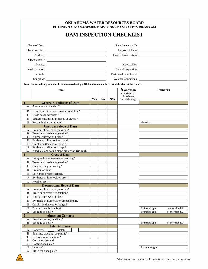
Arkansas Natural Resources Commission - Dam Safety Program100
OKLAHOMA WATER RESOURCES BOARD PLANNING & MANAGEMENT DIVISION - DAM SAFETY PROGRAM
DAM INSPECTION CHECKLIST
Name of Dam: State Inventory ID:
Owner of Dam: Purpose of Dam:
Address: Hazard Classification:
City/State/ZIP
County: Inspected By:
Legal Location: Date of Inspection:
Latitude: Estimated Lake Level:
Longitude Weather Conditions:
Note: Latitude-Longitude should be measured using a GPS and taken on the crest of the dam at the center.
Item
Yes No N/A
1Condition(Satisfactory-
Fair-Poor-Unsatisfactory)
Remarks
1 General Conditions of Dam A Alterations to the dam? B Development in downstream floodplain? C Grass cover adequate? D Settlements, misalignments, or cracks? E Recent high water marks? elevation
2 Upstream Slope of Dam A Erosion, slides, or depressions? B Trees or excessive vegetation? C Animal burrows or holes? D Evidence of livestock on dam? E Cracks, settlement, or bulges? F Evidence of slides or scarps? G Adequate and sound slope protection (rip-rap)?
3 Crest of Dam A Longitudinal or transverse cracking? B Trees or excessive vegetation? C Crest arching or bowing? D Erosion or ruts? E Low areas or depressions? F Evidence of livestock on crest? G Road on crest?
4 Downstream Slope of Dam A Erosion, slides, or depressions? B Trees or excessive vegetation? C Animal burrows or holes? D Evidence of livestock on embankment? E Cracks, settlement, or bulges? F Drains or wells flowing? Estimated gpm clear or cloudy? G Seepage or boils? Estimated gpm clear or cloudy?
5 Abutment Contacts A Erosion, cracks, or slides? B Seepage or boils? Estimated gpm clear or cloudy?
6 Inlet Structure A Concrete? Metal? B Spalling, cracking, or scaling? C Exposed reinforcement? D Corrosion present? E Coating adequate? F Leakage? Estimated gpm G Trash rack adequate? H Obstacles to inlet? I Drawdown operative? Opened & closed
7 Conduit & Outlet A Concrete? Metal? B Spalling, cracking, or scaling? C Exposed reinforcement? D Joints displaced or offset? E Joint material lost? F Leakage of valve or gates? Estimated gpm G Other leakage? Estimated gpm clear or cloudy? H Conduit misaligned? I Outlet or channel obstructed? J Outlet channel eroding?
8 Concrete Spillway A Spalling, cracking, or scaling? B Exposed reinforcement or deterioration? C Joints displaced or offset?
1 of 2Dam Inspection Checklist November 2010
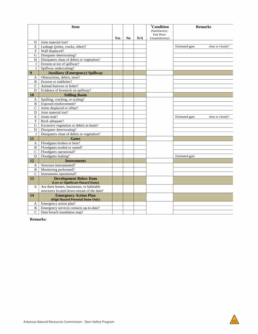
Arkansas Natural Resources Commission - Dam Safety Program 101
2 of 2 Dam Inspection Checklist November 2010
Item
Yes No N/A
1Condition (Satisfactory-
Fair-Poor-Unsatisfactory)
Remarks
D Joint material lost? E Leakage (joints, cracks, other)? Estimated gpm clear or cloudy? F Wall displaced? G Dissipater deteriorating? H Dissipaters clean of debris or vegetation? I Erosion at toe of spillway? J Spillway undercutting?
9 Auxiliary (Emergency) Spillway A Obstructions, debris, trees? B Erosion or sinkholes? C Animal burrows or holes? D Evidence of livestock on spillway?
10 Stilling Basin A Spalling, cracking, or scaling? B Exposed reinforcement? C Joints displaced or offset? D Joint material lost? E Joints leak? Estimated gpm clear or cloudy? F Rock adequate? G Excessive vegetation or debris in basin? H Dissipater deteriorating? I Dissipaters clean of debris or vegetation?
11 Gates A Floodgates broken or bent? B Floodgates eroded or rusted? C Floodgates operational? D Floodgates leaking? Estimated gpm
12 Instruments A Structure instrumented? B Monitoring performed? C Instruments operational?
13 Development Below Dam (Low or Significant Hazard Dams)
A Are there homes, businesses, or habitable
structures located down-stream of the dam?
14 Emergency Action Plan (High Hazard Potential Dams Only)
A Emergency action plan? B Emergency services contacts up-to-date? C Dam breach inundation map?
Remarks:
For High and Significant Hazard-Potential Dams Only Professional Engineer Seal
Name of Engineer:
Date:
Engineering Firm:
Address
City, State, ZIP Signature:
Telephone Number:
1Condition: Please rate the condition of Sections 1 – 11 on inspection form either: Satisfactory, Fair, Poor or Unsatisfactory.
Satisfactory - No existing or potential dam safety deficiencies are recognized. Acceptable performance is expected under all loading conditions (static, hydrologic, seismic) in accordance with the applicable regulatory criteria or tolerable risk guidelines. Fair - No existing dam safety deficiencies are recognized for normal loading conditions. Rare or extreme hydrologic and/or seismic events may result in a dam safety deficiency. Risk may be in the range to take further action. Poor - A dam safety deficiency is recognized for loading conditions which may realistically occur. Remedial action is necessary. Poor may also be used when uncertainties exist as to critical analysis parameters which identify a potential dam safety deficiency. Further investigations and studies are necessary. Unsatisfactory - A dam safety deficiency is recognized that requires immediate or emergency remedial action for problem resolution.

Arkansas Natural Resources Commission - Dam Safety Program102
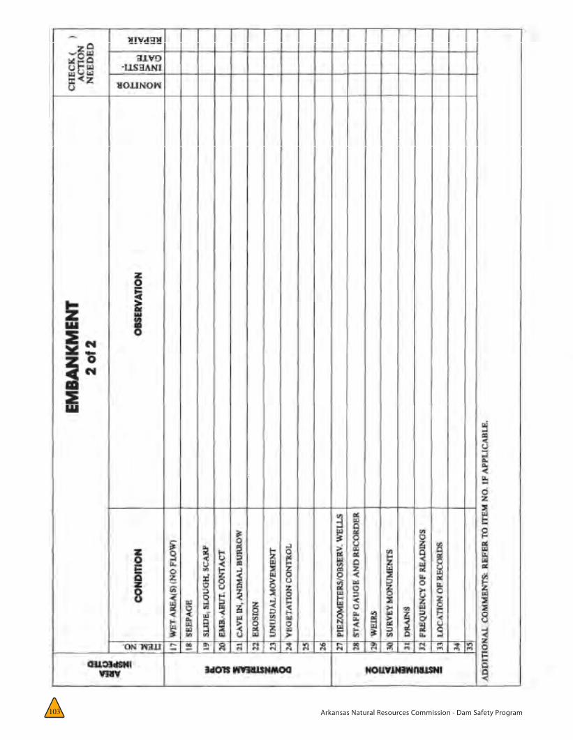
Arkansas Natural Resources Commission - Dam Safety Program103

Arkansas Natural Resources Commission - Dam Safety Program104

Arkansas Natural Resources Commission - Dam Safety Program105
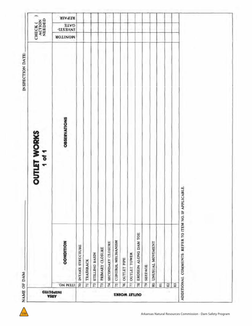
Arkansas Natural Resources Commission - Dam Safety Program106
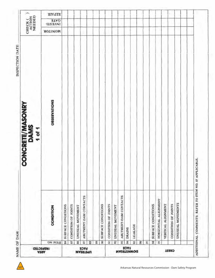
Arkansas Natural Resources Commission - Dam Safety Program107

Arkansas Natural Resources Commission - Dam Safety Program 99
APPENDIX A:
Inspection Equipment and Its Use
ROCK HAMMER: can be used to check question-able-looking riprap or concrete for soundness. Care must be taken not to break through thin spots or cause unnecessary damage.
TAPPING DEVICE: is used to determine the condition of support material behind concrete or asphalt faced dams by firmly tapping the surface of the facing material and listen for a hollow sound. The device can be made from a 1 –inch hardwood dowel with a metal tip firmly fixed to the tapping end, or it can be a length of reinforcing steel.
BINOCULARS: useful for inspecting limited-access areas, especially on concrete dams.
VOLUME CONTAINER AND TIMER: used to make accurate measurements of the rate of leakage. Various container sizes may be required, de-pending on the flow rates.
STAKES AND FLAGGING TAPE: used to mark areas requiring future attention and to stake the limits of existing conditions, such as cracks and wet areas, for future comparison.
GPS RECEIVER: used to collect positional data on locations of interest.
INCLINOMETER : used to measure degree of slope from horizontal.
WATERTIGHT BOOTS: recommended for inspecting areas of the site where water is standing.
SNAKE LEGGINGS OR CHAPS: recommended for situations where heavy brush or snakes may be encountered.
BUG REPELLENT: recommended during warm weather. Insects that bite can reduce the effi-ciency and effectiveness of the inspector.
FIRST-AID KIT: particularly recommended for inspections in areas where poisonous snakes might be present.
NOTEBOOK AND PENCIL: should be available so that observations can be written down at the time they are made, reducing mistakes and avoiding the need to return to the site to refresh the inspector’s memory.
INSPECTION CHECKLIST: serves as a reminder of all important conditions to be examined.
VOICE RECORDER: can be effective in making a record of field observations.
DIGITAL CAMERA: can be used to photograph field conditions. Photographs taken from the same vantage points can also be valuable in comparing past and present conditions. Photo-graphs can also be e-mailed to consultants or the Arkansas Dam Safety Program when neces-sary.
HAND LEVEL: may be needed to accurately locate areas of interest and to determine embankment heights and slope.
PROBE: used to gather information on condi-tions below the surface, such as the depth and softness of a saturated area.
HARD HAT: should be used when inspecting large outlets or working in construction areas.
POCKET TAPE: allows for accurate measure-ments so that meaningful comparisons can be made of movements.
FLASHLIGHT: may be needed to inspect the interior of an outlet in a small dam.
SHOVEL: useful in clearing drain outfalls, re-moving debris, and locating monitoring points.

Arkansas Natural Resources Commission - Dam Safety Program 108
APPENDIX B:
Report Form B
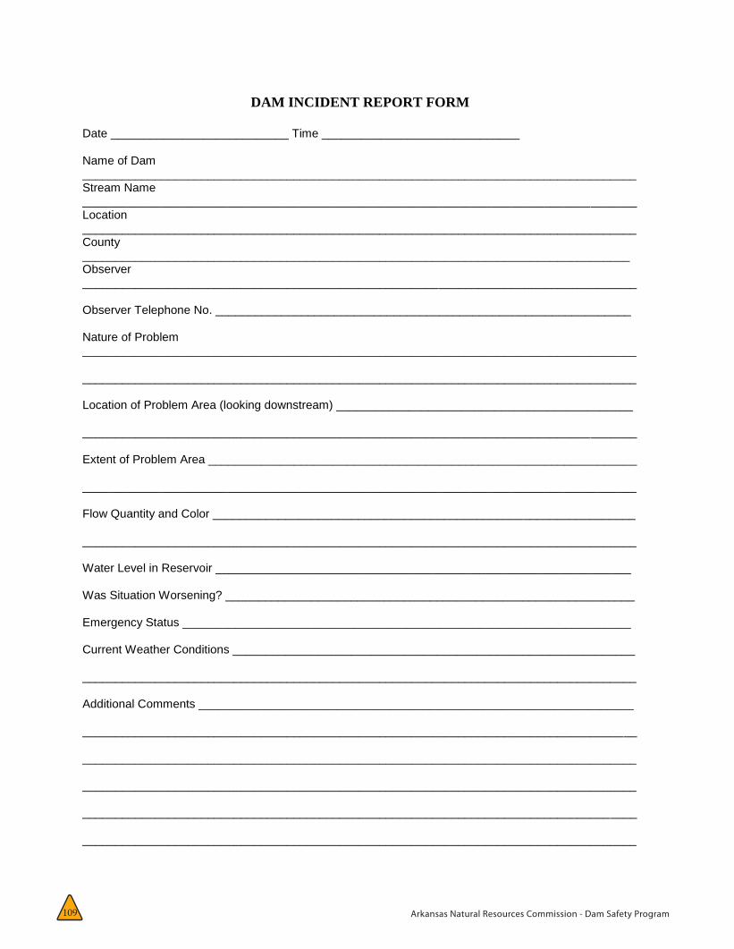
Arkansas Natural Resources Commission - Dam Safety Program109
DAM INCIDENT REPORT FORM Date ___________________________ Time ______________________________ Name of Dam ____________________________________________________________________________________ Stream Name ____________________________________________________________________________________ Location ____________________________________________________________________________________ County ___________________________________________________________________________________ Observer ____________________________________________________________________________________ Observer Telephone No. _______________________________________________________________ Nature of Problem ____________________________________________________________________________________ ____________________________________________________________________________________ Location of Problem Area (looking downstream) _____________________________________________ ____________________________________________________________________________________ Extent of Problem Area _________________________________________________________________ ____________________________________________________________________________________ Flow Quantity and Color ________________________________________________________________ ____________________________________________________________________________________ Water Level in Reservoir _______________________________________________________________ Was Situation Worsening? ______________________________________________________________ Emergency Status ____________________________________________________________________ Current Weather Conditions _____________________________________________________________ ____________________________________________________________________________________ Additional Comments __________________________________________________________________ ____________________________________________________________________________________ ____________________________________________________________________________________ ____________________________________________________________________________________ ____________________________________________________________________________________ ____________________________________________________________________________________
Arkansas Natural Resources Commission - Dam Safety Program 110
APPENDIX C:
Glossary CABUTMENT: That part of a valley side against which a dam is constructed. Right and left abutments are those on respective sides of an observer looking downstream.
AIR-VENT PIPE: A pipe designed to provide air to the outlet conduit to reduce turbulence dur-ing release of water. Extra air is usually neces-sary downstream of constrictions.
APPURTENANT STRUCTURE: Ancillary features of a dam, such as the outlet, spillway, power-house, tunnels, etc.
ARCH DAM: A concrete or masonry dam that is curved so as to transmit the major part of the water pressure to the abutments.
AUXILIARY SPILLWAY: See spillway.
BACKWATER CURVE: The longitudinal profile of the water surface in an open channel where the depth of flow has been increased by an ob-struction, an increase in channel roughness, a decrease in channel width, or a flattening of the bed slope.
BASE WIDTH (BASE THICKNESS): The maxi-mum width or thickness of a dam measured horizontally between upstream and downstream faces and normal (perpendicular) to the axis of the dam but excluding projections for outlets, etc.
BERM: A horizontal step or bench in the slop-ing profile of an embankment dam.
DRAINAGE BLANKET: A drainage layer placed directly over the foundation material.
GROUT BLANKET: See consolidation grouting.
UPSTREAM BLANKET: An impervious layer placed on the reservoir floor upstream of a dam. In case of an embankment dam, the blanket may be connected to the impermeable element in a dam.
BUTTRESS DAM: A dam consisting of a water-tight upstream face supported at intervals on the downstream side by a series of buttresses.
COFFERDAM: A temporary structure enclosing all or part of a construction area so that con-struction can proceed in a dry area. A diversion cofferdam diverts a river into a pipe, channel, or tunnel.
CONCRETE LIFT: In concrete work the vertical distance between successive horizontal con-struction joints.
CONDUIT: A closed channel for conveying discharge through or under a dam.
CONSOLIDATION GROUTING (BLANKET GROUTING): The injection of grout to con-solidate a layer of the foundation, resulting in greater impermeability, strength, or both.
CONSTRUCTION JOINT: The interface between two successive placings or pours of concrete where a bond, not permanent separation, is intended.
CORE WALL: A wall built of impervious mate-rial, usually concrete or asphaltic concrete, in the body of an embankment dam to prevent leakage.
Arkansas Natural Resources Commission - Dam Safety Program111
CREST LENGTH: The length of the top of a dam, including the length of the spillway, pow-erhouse, navigation lock, fish pass, etc., where these structures form part of the length of a dam. If detached from a dam, these structures should not be included.
CRIB DAM: A gravity dam built up of boxes, cribs, crossed timbers, or gabions and filled with earth or rock.
CREST OF DAM: Often used when “top of dam” is meant. To avoid confusion, crest of spillway and top of dam may be used to refer to the over-flow section and the dam proper, respectively.
CULVERT: (a) A drain or waterway built trans-versely under a road, railway, or embankment, usually consisting of a pipe or covered chan-nel of box section. (b) A gallery or waterway constructed through any type of dam, which is normally dry but is used occasionally for dis-charging water, hence the terms scour culvert, drawoff culvert, and spillway culvert.
CUTOFF: An impervious construction or mate-rial which reduces seepage or prevents it from passing through foundation material.
CUTOFF TRENCH: An excavation later to be filled with impervious material to form a cut-off. Sometimes used incorrectly to describe the cutoff itself.
CUTOFF WALL: A wall of impervious material (e.g., concrete, asphaltic concrete, steel-sheet piling) built into the foundation to reduce seep-age under the dam.
DAM: A barrier built across a watercourse for impounding or diverting the flow of water.
DEAD STORAGE: The storage that lies below the invert of the lowest outlet and that, therefore, cannot be withdrawn from the reservoir.
DESIGN FLOOD: See spillway design flood.
DIAPHRAGM: See membrane.
DIKE (LEVEE): A long low embankment whose height is usually less than 5m and whose length is more than 10 times the maximum height. Usually applied to embankments or structures built to protect land from flooding. If built of concrete or masonry, the structure is usually referred to as a flood wall. Also used to describe embankments that block areas on a reservoir rim that are lower than the top of the main dam and that are quite long. In the Mississippi River basin, where the old French word levee has sur-vived, the term now applies to flood-protecting embankments whose height can average up to 15m.
DIVERSION CHANNEL, CANAL, OR TUNNEL: A waterway used to divert water from its natural course. These terms are generally applied to temporary structures such as those designed to bypass water around a dam site during con-struction. “Channel’ is normally used instead of “canal” when the waterway is short. Occa-sionally these terms are applied to permanent structures.
DRAINAGE AREA: An area that drains naturally to a particular point on a river.
DRAINAGE LAYER OR BLANKET: A layer of permeable material in a dam to relieve pore pressure or to facilitate drainage of fill.
DRAINAGE WELLS (RELIEF WELL): A vertical well or borehole, usually downstream of imper-vious cores, grout curtains, or cutoffs, designed to collect and direct seepage through or under a dam to reduce uplift pressure under or within it. A line of such wells forms a drainage curtain.
DRAWDOWN: The lowering of water surface level due to release of water from a reservoir.
EARTHEN DAM OR EARTHFILL DAM: See em-bankment dam.
EMBANKMENT: A slope of fill material, usually earth or rock that is longer than it is high. The sloping side of a dam.
Glossary
Arkansas Natural Resources Commission - Dam Safety Program 112
FLOOD WALL: A concrete wall constructed adjacent to a stream to pre-vent flooding of property on the landward side of the wall, normally constructed in lieu of or to supplement a levee where the land required for levee construction is expensive or not available.
EMBANKMENT DAM (FILL DAM): Any dam constructed of excavated natural materials.
EARTH DAM (EARTHFILL DAM): An embank-ment dam in which more than 50 percent of the total volume is formed of compacted fine-grained material obtained from a borrow area.
HOMOGENEOUS EARTHFILL DAM: An em-bankment dam constructed of similar earth material throughout, except internal drains or drainage blankets; distinguished from a zoned earthfill dam.
HYDRAULIC FILL DAM: An embankment dam constructed of materials, often dredged, that are conveyed and placed by suspension in flowing water.
ROCKFILL DAM: An embankment dam in which more than 50 percent of the total volume com-prises compacted or dumped pervious natural or crushed rock.
ROLLED FILL DAM: An embankment dam of earth or rock in which the material is placed in layers and compacted using rollers or rolling equipment.
ZONED EMBANKMENT DAM: An embankment dam composed of zones of materials selected for different degrees of porosity, permeability and density.
EMERGENCY ACTION PLAN: A predetermined plan of action to be taken to reduce the potential for property damage and loss of lives in an area affected by a dam break.
EMERGENCY SPILLWAY: See spillway.
FACE: The external surface of a structure, e.g., the surface of a wall of a dam.
FAILURE: The uncontrolled release of water from a dam.
FILTER (FILTER ZONE): A band or zone of granu-lar material that is incorporated into a dam and is graded (either naturally or by selection) so as to allow seepage to flow across or down the filter without causing the migration of material from zones adjacent to it.
FLASHBOARDS: A length of timber, concrete, or steel placed on the crest of a spillway to raise the retention water level but that may be quickly removed in the event of a flood, either by a trip-ping device or by deliberately designed failure of the flashboard or its supports.
FLOODPLAIN: An area adjoining a body of wa-ter or natural stream that has been, or may be, covered by flood water.
FLOODPLAIN MANAGEMENT: A management program to reduce the consequences of flood-ing, either by natural runoff or by dam failure, to existing and future properties in a floodplain.
FLOOD ROUTING: The determination of the attenuating effect of storage on a flood passing through a valley, channel, or reservoir.
FLOOD SURCHARGE: The volume or space in a reservoir between the controlled retention water level and the maximum water level. Flood surcharge cannot be retained in the reservoir but will flow over the spillway until the controlled retention water level is reached.
Glossary
Arkansas Natural Resources Commission - Dam Safety Program113
FOUNDATION OF DAM: The natural material on which the dam structure is placed.
FREEBOARD: The vertical distance between a stated water level and the top of a dam. Net freeboard, dry freeboard, flood freeboard, or re-sidual freeboard is the vertical distance between the estimated maximum water level and the top of a dam. Gross freeboard or total freeboard is the vertical distance between the maximum planned controlled retention water level and the top of a dam.
GALLERY: (a) A passageway within the body of a dam or abutment, hence the terms grouting gallery, inspection gallery, and drainage gallery. (b) A long and rather narrow hall, hence the following terms for a power plant: valve gallery, transformer gallery, and busbar gallery.
GATE: A device in which a leaf or member is moved across the waterway from an external position to control or stop the flow.
BULKHEAD GATE: A gate used either for tem-porary closure of a channel or conduit to empty it for inspection or maintenance or for closure against flowing water when the head differ-ence is small, e.g., for diversion tunnel closure. Although a bulkhead gate is usually opened and closed under nearly balanced pressures, it nevertheless may be capable of withstanding a high pressure differential when in the closed position.
CREST GATE (SPILLWAY GATE): A gate on the crest of a spillway to control overflow or reser-voir water level.
EMERGENCY GATE: A standby or reserve gate used only when the normal means of water con-trol is not available.
FIXED WHEEL GATE (FIXED-ROLLER GATE, FIXED-AXLE GATE: A gate having wheels or rollers mounted on the end posts of the gate. The wheels bear against rails fixed in side grooves or gate guides.
FLAP GATE: A gate hinged along one edge, usu-ally either the top or bottom edge. Examples of bottom-hinged flap gates are tilting gates and belly gates, so called due to their shape in cross-section.
FLOOD GATE: A gate to control flood release from a reservoir.
GUARD GATE (GUARD VALVE): A gate or valve that operates fully open or closed. It may function as a secondary device for shutting off the flow of water in case the primary closure device becomes inoperable, but is usually operated under condi-tions of balanced pressure and no flow.
OUTLET GATE: A gate controlling the outflow of water from a reservoir.
RADIAL GATE (TAINTER GATE): A gate with a curved upstream plate and radial arms hinged to piers or other supporting structures.
REGULATING GATE (REGULATING VALVE): A gate or valve that operates under full pressure and flow to throttle and vary the rate of dis-charge.
SLIDE GATE (SLUICE GATE): A gate that can be opened or closed by sliding it in supporting guides.
GRAVITY DAM: A dam constructed of concrete, masonry, or both that relies on its weight for stability.
ARCH GRAVITY DAM: An arch dam in which part of the water pressure is transmitted to the abutments by horizontal thrust and part to the foundation by cantilever.
CURVED GRAVITY DAM: A gravity dam that is curved in plan.
HOLLOW GRAVITY DAM (CELLULAR GRAVITY DAM): A dam that has the outward appearance of a standard gravity dam but that is of hollow construction.
Glossary
Arkansas Natural Resources Commission - Dam Safety Program 114
GROSS STORAGE (RESERVOIR CAPACITY (GROSS CAPACITY OF RESERVOIR): The gross capacity of a reservoir from the river bed up to the maximum controlled retention water level. It includes active, inactive, and dead storage.
GROUT CAP: A concrete pad or wall constructed to facilitate pressure grouting of the grout cur-tain beneath it.
GROUT CURTAIN (GROUT CUTOFF): A barrier produced by injecting grout into a vertical zone, usually narrow horizontally, in the foundation to reduce seepage under a dam.
HEIGHT ABOVE LOWEST FOUNDATION: The maximum height from the lowest point of the general foundation to the top of the dam.
HYDRAULIC HEIGHT: The height to which water rises behind a dam and the difference between the lowest point in the original streambed at the axis of the dam and the maximum controllable water surface.
HYDROGRAPH: A graphic representation of discharge, stage, or other hydraulic property with respect to time for a particular point on a stream. (At times the term is applied to the phe-nomenon the graphic representation describes; hence a flood hydrograph is the passage of a flood discharge past the observation point.)
INCLINOMETER: An instrument, usually consisting of a metal or plastic tube inserted in a drill hole and a sensitized monitor either lowered into the tube or fixed within it. The monitor measures at different points the tube’s inclination to the vertical. By integration, the lateral position at different levels of the tube may be found relative to a point, usually the top or bottom of the tube, assumed to be fixed. The system may be used to measure settlement.
INTAKE: Any structure in a reservoir, dam, or river through which water can be drawn into an aqueduct.
INTERNAL EROSION: See piping.
INUNDATION MAP: A map delineating the area that would be inundated in the event of a failure.
LEAKAGE: Uncontrolled loss of water by flow through a hole or crack.
LINING: With reference to a canal, tunnel, shaft, or reservoir, a coating of asphaltic concrete, reinforced or unreinforced concrete, shotcrete, rubber or plastic to provide water tightness, prevent erosion, reduce friction, or support the periphery of structure. May also refer to lining, such as steel or concrete, of outlet pipe or con-duit.
LOW-LEVEL OUTLET (BOTTOM OUTLET): An opening at a low level from a reservoir generally used for emptying or for scouring sediment and sometimes for irrigation releases.
MASONRY DAM: A dam constructed mainly of stone, brick, or concrete blocks that may or may not be joined with mortar. A dam having only a masonry facing should not be referred to as a masonry dam.
MAXIMUM CROSS-SECTION OF DAM: A cross-section of a dam at the point of its maximum height.
MAXIMUM WATER LEVEL: The maximum water level, including flood surcharge, the dam is de-signed to withstand.
MEMBRANE (DIAPHRAGM): A sheet or thin zone or facing made of a flexible material, sometimes referred to as a diaphragm wall or diaphragm.
MINIMUM OPERATING LEVEL: The lowest level to which the reservoir is drawn down under normal operating conditions.
MORNING GLORY SPILLWAY: See spillway.
Glossary
Arkansas Natural Resources Commission - Dam Safety Program115
NORMAL WATER LEVEL: For a reservoir with a fixed overflow sill the lowest crest level of that sill. For a reservoir whose outflow is controlled wholly or partly by movable gates, siphons or other means, it is the maximum level to which water may rise under normal operating conditions, exclusive of any provision for flood surcharge.
ONE-HUNDRED YEAR (100-YEAR) EXCEEDANCE INTERVAL: The flood magnitude expected to be equaled or exceeded on the average of once in 100 years. It may also be expressed as an exceedance frequency, i.e. a percent chance of being exceeded in any given year.
OUTLET: An opening through which water can be freely discharged from a reservoir.
OVERFLOW DAM: A dam designed to be over-topped.
PARAPET WALL: A solid wall built along the top of a dam for ornament, for the safety of vehicles and pedestrians, or to prevent overtopping.
PEAK FLOW: The maximum instantaneous dis-charge that occurs during a flood. It coincides with the peak of a flood hydrograph.
PERVIOUS ZONE: A part of the cross-section of an embankment dam comprising material of high permeability.
PHREATIC SURFACE: The free surface of groundwater at atmospheric pressure.
PIPING: The progressive development of inter-nal erosion by seepage, appearing downstream as a hole or seam discharging water that con-tains soil particles.
PORE PRESSURE: The interstitial pressure of water within a mass of soil, rock, or concrete.
PRESSURE CELL: An instrument for measuring pressure within a mass of soil, rock, or concrete or at an interface between one and the other.
PRESSURE RELIEF PIPES: Pipes used to relieve uplift or pore water pressure in a dam’s founda-tion or structure.
PROBABLE MAXIMUM FLOOD (PMF): A flood that would result from the most severe combi-nation of critical meteorologic and hydrologic conditions possible in the region.
PROBABLE MAXIMUM PRECIPITATION (PMP): The maximum amount and duration of pre-cipitation that can be expected to occur on a drainage basin.
PUMPED STORAGE RESERVOIR: A reservoir filled entirely or mainly with water pumped from outside its natural drainage area.
REGULATING DAM: A dam impounding a res-ervoir from which water is released to regulate the flow in a river.
RELIEF WELL: See drainage well.
RESERVOIR AREA: The surface area of a reser-voir when filled to controlled retention level.
RESERVOIR ROUTING: The computation by which the interrelated effects of the inflow hy-drograph, reservoir storage, and discharge from the reservoir are evaluated.
RESERVOIR SURFACE: The surface of a reser-voir at any level.
RIPRAP: A layer of large stones, broken rock, or precast blocks placed randomly on the upstream slope of an embankment dam, on a reservoir shore, or on the sides of a channel as a protec-tion against wave action. Very large riprap is sometimes referred to as armoring.
Glossary
PIEZOMETER: An instrument for measuring pore water pressure within soil, rock, or concrete.
Arkansas Natural Resources Commission - Dam Safety Program 116
RISK ASSESSMENT: As applied to dam safety, the process of identifying the likelihood and consequences of dam failure to provide the basis for informed decisions on a course of action.
ROCKFILL DAM: See embankment dam.
ROLLCRETE OR ROLLER - COMPACTED CON-CRETE: A no-slump concrete that can be hauled in dump trucks, spread with a bulldozer or grader, and compacted with a vibratory roller.
SEEPAGE: The interstitial movement of water that may take place through a dam, its founda-tion, or its abutments.
SILL: (a) A submerged structure across a river to control the water level upstream. (b) The crest of a spillway. (c) A horizontal gate seating, made of wood, stone, concrete or metal at the invert of any opening or gap in a structure, hence the expressions gate sill and stoplog sill.
SLOPE: (a) The side of a hill or mountain. (b) The inclined face of a cutting or canal or em-bankment. (c) Inclination from the horizontal. In the United States, it is measured as the ratio of the number of units of horizontal distance to the number of corresponding units of vertical distance. The term is used in English for any inclination and is expressed as a percentage when the slope is gentle, in which case the term gradient is also used.
SLOPE PROTECTION: The protection of a slope against wave action or erosion.
SLUICEWAY: See low-level outlet.
SPILLWAY: A structure over or through which flood flows are discharged. If the flow is con-trolled by gates, it is a controlled spillway; if the elevation of the spillway crest is the only control, it is an uncontrolled spillway.
AUXILIARY SPILLWAY (EMERGENCY SPILLWAY): A secondary spillway designed to operate only during exceptionally large floods.
FUSE-PLUG SPILLWAY: An auxiliary or emer-gency spillway comprising a low embankment or a natural saddle designed to be overtopped and eroded away during a very rare and excep-tionally large flood.
PRIMARY SPILLWAY (PRINCIPAL SPILLWAY): The principal or first-used spillway during flood flows.
SHAFT SPILLWAY (MORNING GLORY SPILLWAY): A vertical or inclined shaft into which flood water spills and then is conducted through, under, or around a dam by means of a conduit or tunnel. If the upper part of the shaft is splayed out and ter-minates in a circular horizontal weir, it is termed a “bellmouth” or “morning glory” spillway.
SIDE CHANNEL SPILLWAY: A spillway whose crest is roughly parallel to the channel immedi-ately downstream of the spillway.
SIPHON SPILLWAY: A spillway with one or more siphons built at crest level. This type of spillway is sometimes used for providing au-tomatic surface-level regulation within narrow limits or when considerable discharge capacity is necessary within a short period of time.
SPILLWAY CHANNEL (SPILLWAY TUNNEL): A channel or tunnel conveying water from the spillway to the river downstream.
SPILLWAY DESIGN FLOOD (SDF): The largest flood that a given project is designed to pass safely. The reservoir inflow-discharge hydro-graph used to estimate the spillway discharge capacity requirements and corresponding maximum surcharge elevation in reservoir.
STILLING BASIN: A basin constructed to dissi-pate the energy of fast-flowing water, e.g., from a spillway or bottom outlet, and to protect the riverbed from erosion.
STOPLOGS: Large logs or timber or steel beams placed on top of each other with their ends held in guides on each side of a channel or conduit
Glossary
Arkansas Natural Resources Commission - Dam Safety Program117
providing a cheaper or easily handled temporary closure than a bulkhead gate.
STORAGE: The retention of water or delay of runoff either b: planned operation, as in a res-ervoir, or by temporary filling of overflow areas, as in the progression of a flood crest through a natural stream channel.
TAILRACE: The tunnel, channel or conduit that conveys the discharge from the turbine to the river, hence the terms tailrace tunnel and tail-race canal.
TAILWATER LEVEL: The level of water in the tailrace at the nearest free surface to the turbine or in the discharge channel immediately down-stream of the dam.
TOE OF DAM: The junction of the downstream face of a dam with the ground surface, referred to as the downstream toe. For an embankment dam the junction of upstream face with ground surface is called the upstream toe.
TOP OF DAM: The elevation of the uppermost surface of a dam, usually a road or walkway, excluding any parapet wall, railings, etc.
TOP THICKNESS (TOP WIDTH): The thickness or width of a dam at the level of the top of the dam. In general, “thickness” is used for gravity and arch dams, “width” for other dams.
TRANSITION ZONE (SEMIPERVIOUS ZONE): A part of the cross-section of a zoned embank-ment dam comprising material of intermediate size between that of an impervious zone and that of a permeable zone.
TRASH RACK: A screen located at an intake to prevent the ingress of debris.
TUNNEL: A long underground excavation usually having a uniform cross-section. Types of tunnel include: headrace tunnel, pressure tunnel, col-lecting tunnel, diversion tunnel, power tunnel, tailrace tunnel, navigation tunnel, access tunnel, scour tunnel, drawoff tunnel, and spillway tunnel.
UNDERSEEPAGE: The interstitial movement of water through a foundation.
UPLIFT: The upward pressure in the pores of a material (interstitial pressure) or on the base of a structure.
UPSTREAM BLANKET: See blanket.
VALVE: A device fitted to a pipeline or orifice in which the closure member is either rotated or moved transversely or longitudinally in the waterway so as to control or stop the flow.
WATERSTOP: A strip of metal, rubber or other material used to prevent leakage through joints between adjacent sections of concrete.
WEIR: (a) A low dam or wall built across a stream to raise the upstream water level, called fixed-crest weir when uncontrolled. (b) A struc-ture built across a stream or channel for mea-suring flow, sometimes called a measuring weir or gauging weir. Types of weir include broad-crested weir, sharp-crested weir, drowned weir, and submerged weir.
Glossary
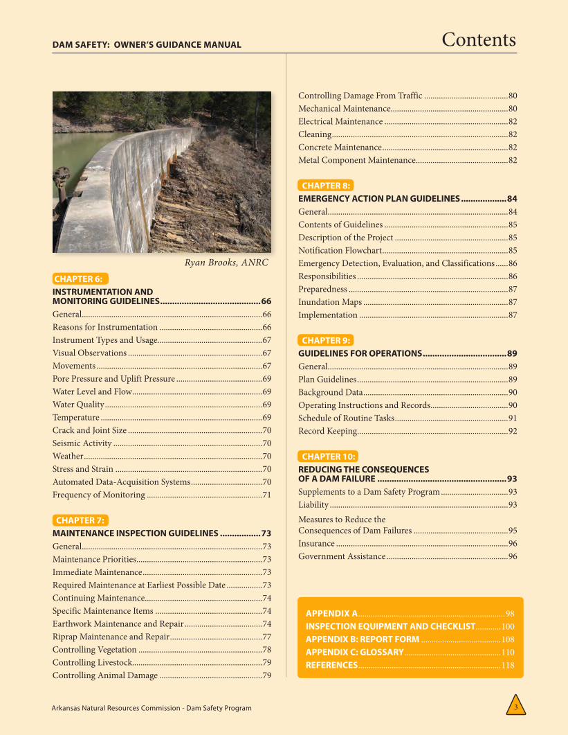
Arkansas Natural Resources Commission - Dam Safety Program 3
Contents
CHAPTER 6:INSTRUMENTATION AND MONITORING GUIDELINES ..........................................66General ......................................................................................66Reasons for Instrumentation .................................................66Instrument Types and Usage..................................................67Visual Observations ................................................................67Movements ...............................................................................67Pore Pressure and Uplift Pressure .........................................69Water Level and Flow ..............................................................69Water Quality ...........................................................................69Temperature .............................................................................69Crack and Joint Size ................................................................70Seismic Activity .......................................................................70Weather .....................................................................................70Stress and Strain ......................................................................70Automated Data-Acquisition Systems ..................................70Frequency of Monitoring .......................................................71
CHAPTER 7: MAINTENANCE INSPECTION GUIDELINES .................73General ......................................................................................73Maintenance Priorities ............................................................73Immediate Maintenance .........................................................73Required Maintenance at Earliest Possible Date .................73Continuing Maintenance........................................................74Specific Maintenance Items ...................................................74Earthwork Maintenance and Repair .....................................74Riprap Maintenance and Repair ............................................77Controlling Vegetation ...........................................................78Controlling Livestock..............................................................79Controlling Animal Damage .................................................79
Controlling Damage From Traffic ........................................80Mechanical Maintenance ........................................................80Electrical Maintenance ...........................................................82Cleaning ....................................................................................82Concrete Maintenance ............................................................82Metal Component Maintenance ............................................82
CHAPTER 8: EMERGENCY ACTION PLAN GUIDELINES ...................84General ......................................................................................84Contents of Guidelines ...........................................................85Description of the Project ......................................................85Notification Flowchart ............................................................85Emergency Detection, Evaluation, and Classifications ......86Responsibilities ........................................................................86Preparedness ............................................................................87Inundation Maps .....................................................................87Implementation .......................................................................87
CHAPTER 9: GUIDELINES FOR OPERATIONS ...................................89General ......................................................................................89Plan Guidelines ........................................................................89Background Data .....................................................................90Operating Instructions and Records .....................................90Schedule of Routine Tasks ......................................................91Record Keeping ........................................................................92
CHAPTER 10: REDUCING THE CONSEQUENCES OF A DAM FAILURE ......................................................93Supplements to a Dam Safety Program ................................93Liability .....................................................................................93Measures to Reduce the Consequences of Dam Failures .............................................95Insurance ..................................................................................96Government Assistance ..........................................................96
DAM SAFETY: OWNER’S GUIDANCE MANUAL
APPENDIX A ......................................................................98INSPECTION EQUIPMENT AND CHECKLIST ............100APPENDIX B: REPORT FORM ......................................108APPENDIX C: GLOSSARY ..............................................110REFERENCES ....................................................................118
Ryan Brooks, ANRC
Arkansas Natural Resources Commission - Dam Safety Program 4
DAM SAFETY:
An Owner’s Guidance Manual
Introduction to Dam Safety
The need for dam safety is urgent. Across the United States thousands of dams are now in place with many more built each year. Dams—essential elements of the national infrastructure—supply water for households and businesses and cooling water for power
plants, offer opportunities for recreation, and help control f loods. Should a dam fail, many lives and many dollars’ worth of property are at risk. The legal and moral responsibility for dam safety rests with the dam owner.
Existing dams are aging and new ones are being built in hazardous areas. At the same time, devel-opment continues in potential inundation zones downstream. More people are at risk from dam failure than ever, despite better engineering and construction methods, and continued deaths and property losses from dam failures are to be expected.
Society and individuals alike may profit from dam operations. Dam ownership, however, is neither justified nor effective if one cannot assure the safety of citizens and property. The costs of dam safety are small in comparison to the consequences following a dam failure, particularly in today’s litigious society. Liability due to dam failure can easily offset years of profitability.
You can directly influence the safety of a dam by developing a safety program which includes inspection, monitoring through instrumentation, maintenance of the structure, and proactive emergency planning. A high-quality safety program is attuned to the dam structure and its im-mediate environment and depends on the owner’s knowledge of the dam and how it works.
Lakes in Arkansas and in other parts of the country may either be human-built or exist because of geologic activities such as landslides, erosion, or glaciation. The majority of dams are human structures constructed of earthfill or concrete. It is important that you, as a dam owner, be aware of the different types of dams, their essential components and their function, as well as the important physical conditions that likely influence them.
As in the case with buildings, highways, and other works that we construct, dams require an on-going maintenance program to insure their continued useful life. This fact has not always been appreciated. Often there is a tendency to neglect them once construction is completed.
As is the case with buildings, highways, and other works that we construct, dams require an on-going maintenance program to ensure their continued useful life.
This fact has not always been fully appreciated. Often there is a tendency to neglect them once construction is completed.
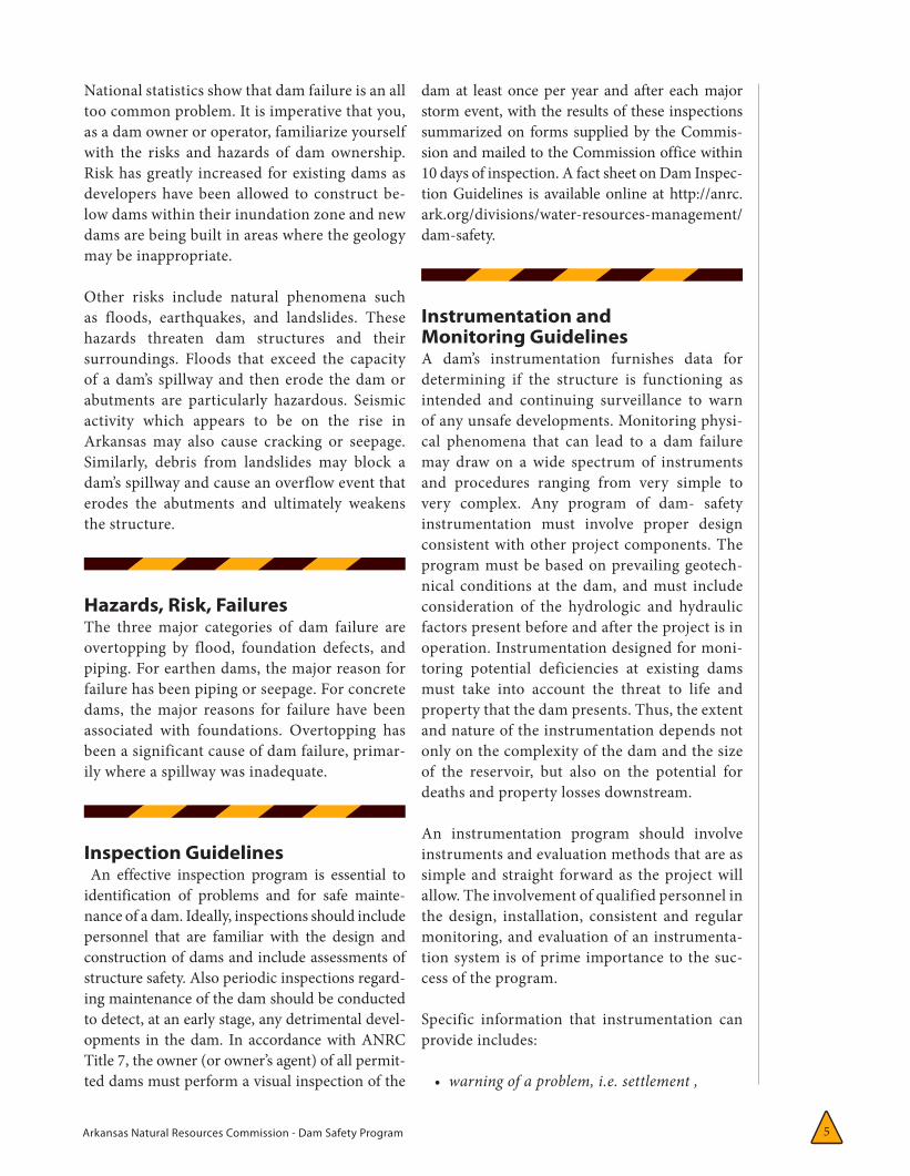
Arkansas Natural Resources Commission - Dam Safety Program 5
National statistics show that dam failure is an all too common problem. It is imperative that you, as a dam owner or operator, familiarize yourself with the risks and hazards of dam ownership. Risk has greatly increased for existing dams as developers have been allowed to construct be-low dams within their inundation zone and new dams are being built in areas where the geology may be inappropriate.
Other risks include natural phenomena such as floods, earthquakes, and landslides. These hazards threaten dam structures and their surroundings. Floods that exceed the capacity of a dam’s spillway and then erode the dam or abutments are particularly hazardous. Seismic activity which appears to be on the rise in Arkansas may also cause cracking or seepage. Similarly, debris from landslides may block a dam’s spillway and cause an overflow event that erodes the abutments and ultimately weakens the structure.
Hazards, Risk, FailuresThe three major categories of dam failure are overtopping by flood, foundation defects, and piping. For earthen dams, the major reason for failure has been piping or seepage. For concrete dams, the major reasons for failure have been associated with foundations. Overtopping has been a significant cause of dam failure, primar-ily where a spillway was inadequate.
Inspection Guidelines An effective inspection program is essential to identification of problems and for safe mainte-nance of a dam. Ideally, inspections should include personnel that are familiar with the design and construction of dams and include assessments of structure safety. Also periodic inspections regard-ing maintenance of the dam should be conducted to detect, at an early stage, any detrimental devel-opments in the dam. In accordance with ANRC Title 7, the owner (or owner’s agent) of all permit-ted dams must perform a visual inspection of the
dam at least once per year and after each major storm event, with the results of these inspections summarized on forms supplied by the Commis-sion and mailed to the Commission office within 10 days of inspection. A fact sheet on Dam Inspec-tion Guidelines is available online at http://anrc.ark.org/divisions/water-resources-management/dam-safety.
Instrumentation and Monitoring GuidelinesA dam’s instrumentation furnishes data for determining if the structure is functioning as intended and continuing surveillance to warn of any unsafe developments. Monitoring physi-cal phenomena that can lead to a dam failure may draw on a wide spectrum of instruments and procedures ranging from very simple to very complex. Any program of dam- safety instrumentation must involve proper design consistent with other project components. The program must be based on prevailing geotech-nical conditions at the dam, and must include consideration of the hydrologic and hydraulic factors present before and after the project is in operation. Instrumentation designed for moni-toring potential deficiencies at existing dams must take into account the threat to life and property that the dam presents. Thus, the extent and nature of the instrumentation depends not only on the complexity of the dam and the size of the reservoir, but also on the potential for deaths and property losses downstream.
An instrumentation program should involve instruments and evaluation methods that are as simple and straight forward as the project will allow. The involvement of qualified personnel in the design, installation, consistent and regular monitoring, and evaluation of an instrumenta-tion system is of prime importance to the suc-cess of the program.
Specific information that instrumentation can provide includes:
• warning of a problem, i.e. settlement ,
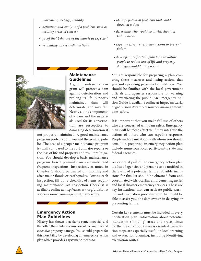
Arkansas Natural Resources Commission - Dam Safety Program 6
movement, seepage, stability
• definitionandanalysisofaproblem,suchaslocatingareasofconcern
• proofthatbehaviorofthedamisasexpected
• evaluatinganyremedialactions
Maintenance GuidelinesA good maintenance pro-gram will protect a dam against deterioration and prolong its life. A poorly maintained dam will deteriorate, and may fail. Nearly all the components of a dam and the materi-als used for its construc-tion are susceptible to damaging deterioration if
not properly maintained. A good maintenance program protects both you and the general pub-lic. The cost of a proper maintenance program is small compared to the cost of major repairs or the loss of life and property and resultant litiga-tion. You should develop a basic maintenance program based primarily on systematic and frequent inspections. Inspections, as noted in Chapter 5, should be carried out monthly and after major floods or earthquakes. During each inspection, fill out a checklist of items requir-ing maintenance. An Inspection Checklist is available online at http://anrc.ark.org/divisions/water-resources-management/dam-safety.
Emergency Action Plan GuidelinesHistory has shown that dams sometimes fail and that often these failures cause loss of life, injuries and extensive property damage. You should prepare for this possibility by developing an emergency action plan which provides a systematic means to:
•identifypotentialproblemsthatcouldthreatenadam
•determinewhowouldbeatriskshouldafailureoccur
•expediteeffectiveresponseactionstopreventfailure
•developanotificationplanforevacuatingpeopletoreducelossoflifeandpropertydamageshouldfailureoccur
You are responsible for preparing a plan cov-ering these measures and listing actions that you and operating personnel should take. You should be familiar with the local government officials and agencies responsible for warning and evacuating the public. An Emergency Ac-tion Guide is available online at http://anrc.ark.org/divisions/water-resources-management/dam-safety.
It is important that you make full use of others who are concerned with dam safety. Emergency plans will be more effective if they integrate the actions of others who can expedite response. People and organizations with whom you should consult in preparing an emergency action plan include numerous local participants, state and federal agencies.
An essential part of the emergency action plan is a list of agencies and persons to be notified in the event of a potential failure. Possible inclu-sions for this list should be obtained from and coordinated with local law enforcement agencies and local disaster emergency services. These are key institutions that can activate public warn-ing and evacuation procedures or that might be able to assist you, the dam owner, in delaying or preventing failure.
Certain key elements must be included in every notification plan. Information about potential inundation (flooding) areas and travel times for the breach (flood) wave is essential. Inunda-tion maps are especially useful in local warning and evacuation planning, including identifying evacuation routes.
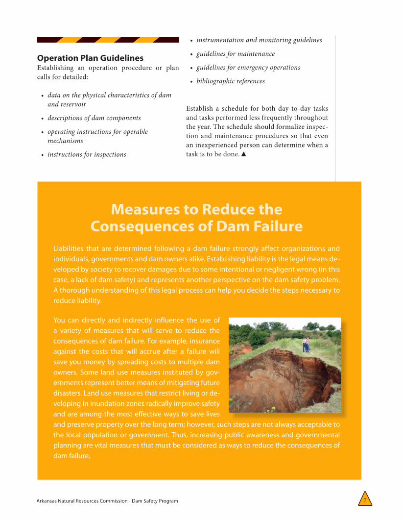
Arkansas Natural Resources Commission - Dam Safety Program 7
Operation Plan GuidelinesEstablishing an operation procedure or plan calls for detailed:
• dataonthephysicalcharacteristicsofdamandreservoir
• descriptionsofdamcomponents
• operatinginstructionsforoperablemechanisms
• instructionsforinspections
Measures to Reduce the Consequences of Dam Failure
Liabilities that are determined following a dam failure strongly affect organizations and individuals, governments and dam owners alike. Establishing liability is the legal means de-veloped by society to recover damages due to some intentional or negligent wrong (in this case, a lack of dam safety) and represents another perspective on the dam safety problem. A thorough understanding of this legal process can help you decide the steps necessary to reduce liability.
You can directly and indirectly influence the use of a variety of measures that will serve to reduce the consequences of dam failure. For example, insurance against the costs that will accrue after a failure will save you money by spreading costs to multiple dam owners. Some land use measures instituted by gov-ernments represent better means of mitigating future disasters. Land use measures that restrict living or de-veloping in inundation zones radically improve safety and are among the most effective ways to save lives and preserve property over the long term; however, such steps are not always acceptable to the local population or government. Thus, increasing public awareness and governmental planning are vital measures that must be considered as ways to reduce the consequences of dam failure.
• instrumentationandmonitoringguidelines
• guidelinesformaintenance
• guidelinesforemergencyoperations
• bibliographicreferences
Establish a schedule for both day-to-day tasks and tasks performed less frequently throughout the year. The schedule should formalize inspec-tion and maintenance procedures so that even an inexperienced person can determine when a task is to be done.
Arkansas Natural Resources Commission - Dam Safety Program 10
CH
APTER 1dam fail during this term. Thus, the potential
owner must carefully inspect the structural integrity of any dam prior to purchase and then inspect, maintain, and repair it thereafter.
Legally, the dam owner must do what is neces-sary to avoid injuring persons or property which usually applies to circumstances and situations which a reasonable person could anticipate. In order to meet your responsibility to maintain the dam in a reasonable and safe condition, you, the owner, should conduct regular inspections of the dam and maintain or repair deficient items. Regular inspections by qualified professionals are necessary to identify and correct any problems.
A dam owner should have a thorough understand-ing of the dam’s physical and social environment. This would include: knowledge of natural and technological hazards that threaten it, an under-standing of the developing human settlement patterns around the dam, and an understanding of any events that can lead to structural failure.
It is a good idea for every owner of a dam to pause and consider what lies below their dam. Several questions need to be asked.
• Whatisthenatureofthelandusedownstream:woodedoragriculturalland,scatteredhomes,roads,villages,urban?
• Howmanystructuresarelocatedwithinahalfmile,amileorseveralmilesofthedam?
• Howaredownstreamstructureslocatedwithregardtothewatercourseorfloodplain,withrespecttobothdistancesfromthewatercourseorriverandelevationaboveit?
• Whatisthefirst-floorelevationofhomeslocateddownstream.Aretheyonlyafewfeetabovethelevelofthewatersurface,oraretheyonbluffshighaboveitandoutofdanger?
• Isthevalleybelowthedamcharacterizedbysteephills,oristhereabroadfloodplain?Thisisanimportantconsideration,asitdetermineswhetherwaterreleasedina
damfailureorduringfloodingwouldsoonspreadoutandloseitsforceorwhetheradestructivewallofwaterwouldtravelalongdistancedownstream.
Owning a dam brings many different concerns and possible rewards, but in the end success will largely be measured by a continuing record of safety.
Owners can also influence the safety of dams in more direct ways. They can and should de-velop their own safety programs, which should include such important elements as inspection, monitoring through instrumentation, mainte-nance, emergency action planning, and proper operation. Such programs are directly related to a specific dam’s structure and its immediate environment and depend on the owner’s knowl-edge of the dam and how it works.
The Role of Consultants in Dam SafetyA dam is a special kind of structure, simple in concept but with many complicated com-ponents. There is no such thing as a standard dam design; furthermore, each dam site is unique. The existence of a dam necessitates the involvement of many specialists to analyze, design, build, inspect, and repair it. This wide variety of consultants will include civil, geo-technical, mechanical, and electrical engineers, geologists and hydrologists.
As owner, you should know more about your dam than anyone else. A consultant can advise you on such important items as:
• thedesignandconstructionofanewdam
• theoverallstabilityofthedamundernormalandfloodconditions
• anyrepairsormaintenanceneededbythedamandappurtenantworks
• theseverityofanyproblemsandindicateinwhatordertorepairthem
• costestimatesforrepairwork
• adequacyofthespillwaytopassthedesignflood
Arkansas Natural Resources Commission - Dam Safety Program 11
• anassessmentofdownstreamhazards
• thedamowner’spreparationandprocedurestodealwithemergencyconditions
Hazardous conditions at the dam should be reported verbally and in writing to the dam owner and the ANRC. It is uncommon that a dam owner has all of the technical skills needed to monitor the condition of the dam. Thus, the role of the consulting engineer is critical in dam safety
Role of the Arkansas Natural Resources CommissionThe Arkansas Natural Resources Commission is responsible for administrating state dam safety laws. The staff of the ANRC has four primary areas of activity in the dam safety program: (1) review and approval of plans and specifications of new dams, (2) review of plans and specifications for repairs, modification, or rehabilitation work, (3) periodic inspections of construction work on new and existing dams, and (4) review of inspection reports and approval of emergency action plans.
Arkansas Natural Resources Commission - Dam Safety Program 8
CH
APTER 1
CHAPTER 1:
An Approach to Dam Safety 1public and private agencies, and private citizens. Typical reasons for building dams include water storage for human consumption, agricultural production, power generation, flood control, reduction of soil erosion, industrial use, and recreation. Thus, dam owners serve society by meeting important state needs and may also personally profit from dam operations. How-ever, those are not sufficient reasons for build-ing or owning a dam if the owner cannot keep people and property safe in potential inunda-tion zones.
Both financially and morally, successful dam ownership and the maintenance of safety standards go hand in hand. Investment in dam safety should be accepted as an integral part of project costs and not viewed as an expendable item that can be eliminated if a budget becomes tight (Jansen, 1980). The potential cost and sta-tistical likelihood of dam failure to both life and property are simply too high to ignore.
As national needs for water intensify and its value increases, more dams are being built. At the same time, many existing dams are reach-ing or passing their design life spans and, for various reasons, people continue to settle near dams. As builders use poorer sites for dams or as areas below a dam develop, the job of protect-ing life and property becomes more difficult. Therefore, as dam construction continues and the population grows, exposure of the public to dam failure hazards increases and the overall safety problem becomes more difficult.
General
This manual is a safety guide for the dam owner. The continuing need for dam safety is critical because of the thousands
of dams now in place and the many new ones being built each year. Although these dams are essential elements of the national infrastructure, the risks to the public posed by their possible failure are great; a large and growing number of lives and valuable property are at stake. Though many are concerned about dam safety, the legal and moral responsibility essentially rests with the dam owner.
Urgency for SafetyThe critical need for dam safety is clear. World and national statistics on dam failures show an unaccept-able record of deaths and property losses. The record for U.S. losses from major dam failures in recent years, shown in Table 1 is also discouraging. Actual national losses are much higher than indicated be-cause the statistics shown exclude small dam failures and combinations of dam failure with natural flood-ing events. Two examples are dams that failed near Hearne, Texas in May 2004 and the Johnstown, Pennsylvania, disaster of 1889 which is still regarded as one of the nation’s great catastrophes. The poten-tial for future similar catastrophes due to dam failure remains strong. Only a cooperative effort in dam safety involving owners and communities can lessen this potential.
Dam Ownership and SafetyThis manual can be applied to dams owned and operated by a wide range of organizations and people, including state and local governments,
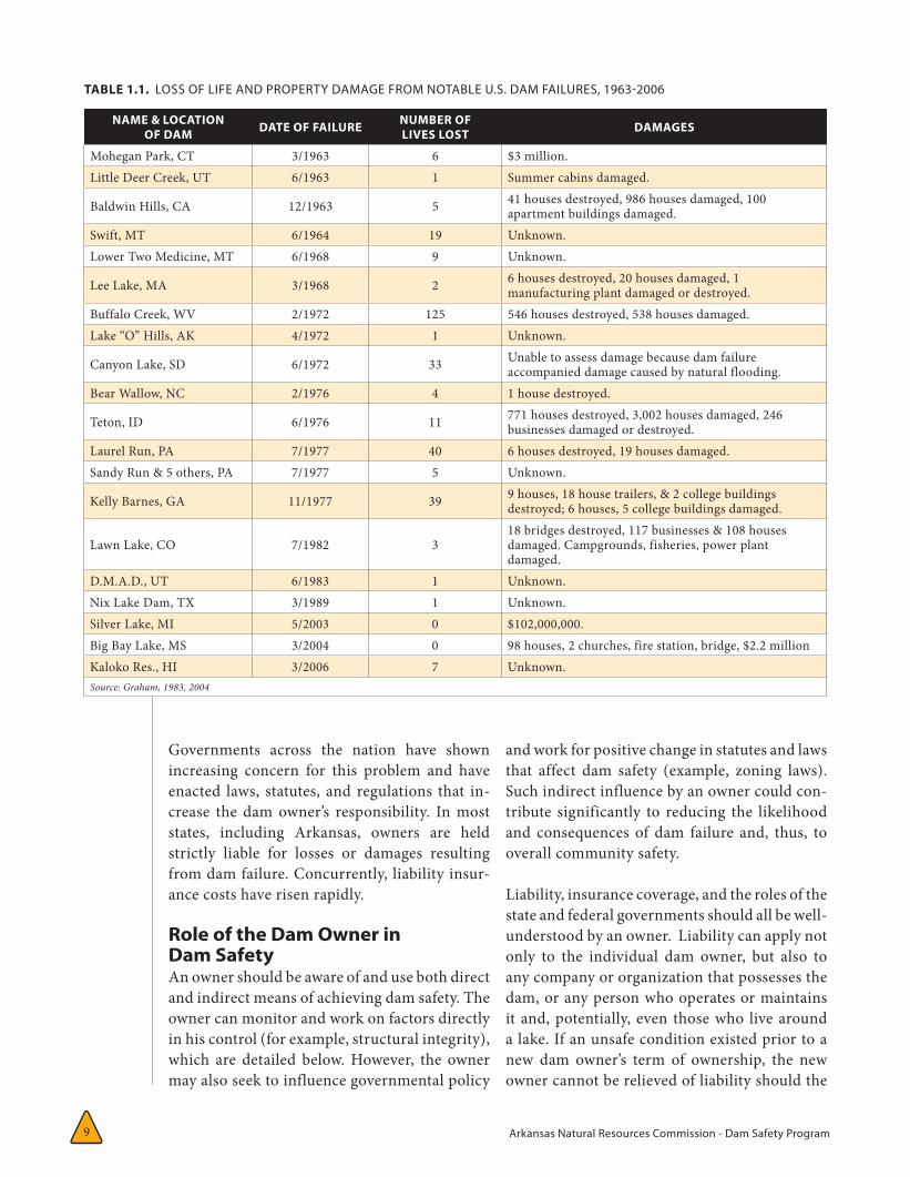
Arkansas Natural Resources Commission - Dam Safety Program 9
NAME & LOCATIONOF DAM DATE OF FAILURE NUMBER OF
LIVES LOST DAMAGES
Mohegan Park, CT 3/1963 6 $3 million. Little Deer Creek, UT 6/1963 1 Summer cabins damaged.
Baldwin Hills, CA 12/1963 5 41 houses destroyed, 986 houses damaged, 100 apartment buildings damaged.
Swift, MT 6/1964 19 Unknown. Lower Two Medicine, MT 6/1968 9 Unknown.
Lee Lake, MA 3/1968 2 6 houses destroyed, 20 houses damaged, 1 manufacturing plant damaged or destroyed.
Buffalo Creek, WV 2/1972 125 546 houses destroyed, 538 houses damaged. Lake “O” Hills, AK 4/1972 1 Unknown.
Canyon Lake, SD 6/1972 33 Unable to assess damage because dam failure accompanied damage caused by natural flooding.
Bear Wallow, NC 2/1976 4 1 house destroyed.
Teton, ID 6/1976 11 771 houses destroyed, 3,002 houses damaged, 246 businesses damaged or destroyed.
Laurel Run, PA 7/1977 40 6 houses destroyed, 19 houses damaged. Sandy Run & 5 others, PA 7/1977 5 Unknown.
Kelly Barnes, GA 11/1977 39 9 houses, 18 house trailers, & 2 college buildings destroyed; 6 houses, 5 college buildings damaged.
Lawn Lake, CO 7/1982 318 bridges destroyed, 117 businesses & 108 houses damaged. Campgrounds, fisheries, power plant damaged.
D.M.A.D., UT 6/1983 1 Unknown. Nix Lake Dam, TX 3/1989 1 Unknown. Silver Lake, MI 5/2003 0 $102,000,000. Big Bay Lake, MS 3/2004 0 98 houses, 2 churches, fire station, bridge, $2.2 million Kaloko Res., HI 3/2006 7 Unknown. Source: Graham, 1983, 2004
TABLE 1.1. LOSS OF LIFE AND PROPERTY DAMAGE FROM NOTABLE U.S. DAM FAILURES, 1963-2006
Governments across the nation have shown increasing concern for this problem and have enacted laws, statutes, and regulations that in-crease the dam owner’s responsibility. In most states, including Arkansas, owners are held strictly liable for losses or damages resulting from dam failure. Concurrently, liability insur-ance costs have risen rapidly.
Role of the Dam Owner in Dam SafetyAn owner should be aware of and use both direct and indirect means of achieving dam safety. The owner can monitor and work on factors directly in his control (for example, structural integrity), which are detailed below. However, the owner may also seek to influence governmental policy
and work for positive change in statutes and laws that affect dam safety (example, zoning laws). Such indirect influence by an owner could con-tribute significantly to reducing the likelihood and consequences of dam failure and, thus, to overall community safety.
Liability, insurance coverage, and the roles of the state and federal governments should all be well-understood by an owner. Liability can apply not only to the individual dam owner, but also to any company or organization that possesses the dam, or any person who operates or maintains it and, potentially, even those who live around a lake. If an unsafe condition existed prior to a new dam owner’s term of ownership, the new owner cannot be relieved of liability should the
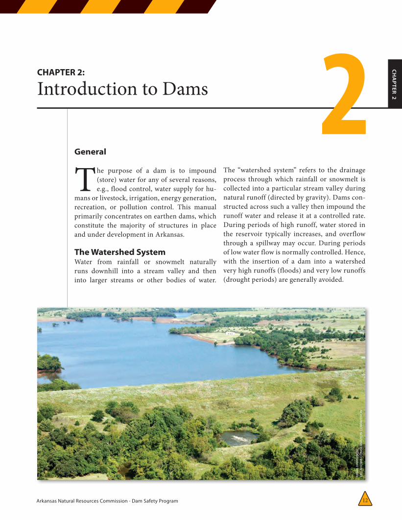
Arkansas Natural Resources Commission - Dam Safety Program 12
CH
APTER 2
CHAPTER 2:
Introduction to Dams 2General
The purpose of a dam is to impound (store) water for any of several reasons, e.g., flood control, water supply for hu-
mans or livestock, irrigation, energy generation, recreation, or pollution control. This manual primarily concentrates on earthen dams, which constitute the majority of structures in place and under development in Arkansas.
The Watershed SystemWater from rainfall or snowmelt naturally runs downhill into a stream valley and then into larger streams or other bodies of water.
The “watershed system” refers to the drainage process through which rainfall or snowmelt is collected into a particular stream valley during natural runoff (directed by gravity). Dams con-structed across such a valley then impound the runoff water and release it at a controlled rate. During periods of high runoff, water stored in the reservoir typically increases, and overflow through a spillway may occur. During periods of low water flow is normally controlled. Hence, with the insertion of a dam into a watershed very high runoffs (floods) and very low runoffs (drought periods) are generally avoided.
MA
RK
HA
RR
ISO
N,
OKLA
HOMA C
ON
SE
RVA
TIO
N C
OM
MIS
SIO
N
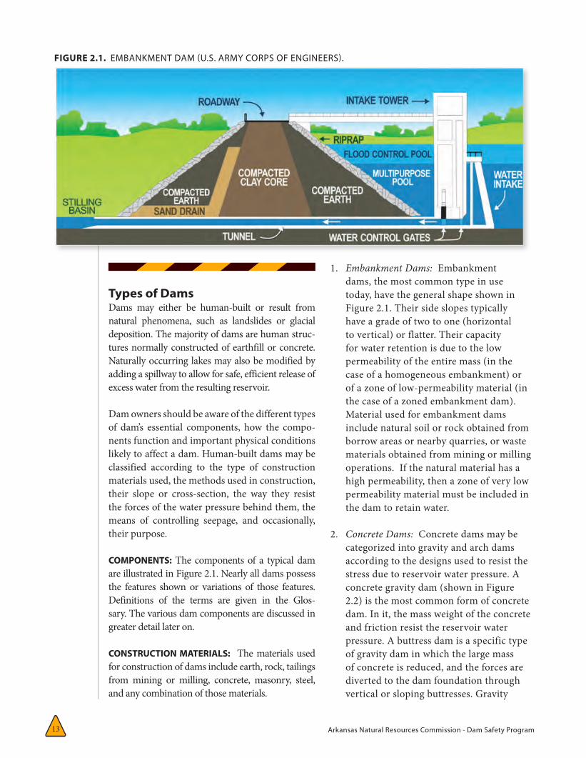
Arkansas Natural Resources Commission - Dam Safety Program 13
Types of DamsDams may either be human-built or result from natural phenomena, such as landslides or glacial deposition. The majority of dams are human struc-tures normally constructed of earthfill or concrete. Naturally occurring lakes may also be modified by adding a spillway to allow for safe, efficient release of excess water from the resulting reservoir.
Dam owners should be aware of the different types of dam’s essential components, how the compo-nents function and important physical conditions likely to affect a dam. Human-built dams may be classified according to the type of construction materials used, the methods used in construction, their slope or cross-section, the way they resist the forces of the water pressure behind them, the means of controlling seepage, and occasionally, their purpose.
COMPONENTS: The components of a typical dam are illustrated in Figure 2.1. Nearly all dams possess the features shown or variations of those features. Definitions of the terms are given in the Glos-sary. The various dam components are discussed in greater detail later on.
CONSTRUCTION MATERIALS: The materials used for construction of dams include earth, rock, tailings from mining or milling, concrete, masonry, steel, and any combination of those materials.
1. Embankment Dams: Embankment dams, the most common type in use today, have the general shape shown in Figure 2.1. Their side slopes typically have a grade of two to one (horizontal to vertical) or flatter. Their capacity for water retention is due to the low permeability of the entire mass (in the case of a homogeneous embankment) or of a zone of low-permeability material (in the case of a zoned embankment dam). Material used for embankment dams include natural soil or rock obtained from borrow areas or nearby quarries, or waste materials obtained from mining or milling operations. If the natural material has a high permeability, then a zone of very low permeability material must be included in the dam to retain water.
2. Concrete Dams: Concrete dams may be categorized into gravity and arch dams according to the designs used to resist the stress due to reservoir water pressure. A concrete gravity dam (shown in Figure 2.2) is the most common form of concrete dam. In it, the mass weight of the concrete and friction resist the reservoir water pressure. A buttress dam is a specific type of gravity dam in which the large mass of concrete is reduced, and the forces are diverted to the dam foundation through vertical or sloping buttresses. Gravity
FIGURE 2.1. EMBANKMENT DAM (U.S. ARMY CORPS OF ENGINEERS).
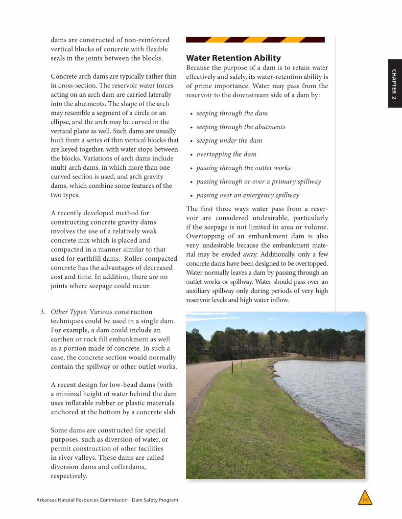
Arkansas Natural Resources Commission - Dam Safety Program 14
CH
APTER 2
dams are constructed of non-reinforced vertical blocks of concrete with flexible seals in the joints between the blocks.
Concrete arch dams are typically rather thin in cross-section. The reservoir water forces acting on an arch dam are carried laterally into the abutments. The shape of the arch may resemble a segment of a circle or an ellipse, and the arch may be curved in the vertical plane as well. Such dams are usually built from a series of thin vertical blocks that are keyed together, with water stops between the blocks. Variations of arch dams include multi-arch dams, in which more than one curved section is used, and arch gravity dams, which combine some features of the two types.
A recently developed method for constructing concrete gravity dams involves the use of a relatively weak concrete mix which is placed and compacted in a manner similar to that used for earthfill dams. Roller-compacted concrete has the advantages of decreased cost and time. In addition, there are no joints where seepage could occur.
3. Other Types: Various construction techniques could be used in a single dam. For example, a dam could include an earthen or rock fill embankment as well as a portion made of concrete. In such a case, the concrete section would normally contain the spillway or other outlet works.
A recent design for low-head dams (with a minimal height of water behind the dam uses inflatable rubber or plastic materials anchored at the bottom by a concrete slab.
Some dams are constructed for special purposes, such as diversion of water, or permit construction of other facilities in river valleys. These dams are called diversion dams and cofferdams, respectively.
Water Retention AbilityBecause the purpose of a dam is to retain water effectively and safely, its water-retention ability is of prime importance. Water may pass from the reservoir to the downstream side of a dam by:
• seepingthroughthedam
• seepingthroughtheabutments
• seepingunderthedam
• overtoppingthedam
• passingthroughtheoutletworks
• passingthroughoroveraprimaryspillway
• passingoveranemergencyspillway
The first three ways water pass from a reser-voir are considered undesirable, particularly if the seepage is not limited in area or volume. Overtopping of an embankment dam is also very undesirable because the embankment mate-rial may be eroded away. Additionally, only a few concrete dams have been designed to be overtopped. Water normally leaves a dam by passing through an outlet works or spillway. Water should pass over an auxiliary spillway only during periods of very high reservoir levels and high water inflow.
FIGURE 2.2. CONCRETE GRAVITY DAM (U.S. ARMY CORPS OF ENGINEERS).

Arkansas Natural Resources Commission - Dam Safety Program 15
tion, resulting in even greater erosion and probable dam failure.
Obviously, large, unrestricted seepage is undesirable. To minimize this possibility, dams are constructed with internal impermeable barriers and internal drainage facilities such as drainpipes or filter sys-tems, or other drainage systems such as toe, blanket, or chimney drains.
Flow through a dam foundation may be diminished by grouting known or suspected highly permeable material, constructing a cutoff wall or trench below a dam, or constructing an upstream impermeable blanket. Figure 2.3 illustrates a cutoff trench.
In summary, the overall water retention ability of a dam depends on its permeability, the abutments, the foundation, and the efforts made to reduce that permeability or restrict the flow of water through these components. Should high permeability oc-cur, seepage can lead to piping, which will likely result in failure.
Release of WaterIntentional release of water, as stated earlier, is confined to water releases through a service spillway or outlet works or over emergency spillways.
PRINCIPAL OR MECHANICAL SPILLWAY: The principal or mechanical spillway maintains the normal water level in the reservoir. Its function is to pass expected flood flows past the dam safely and without erosion. It may consist of a pipe through the dam or a system of gates that discharge water into a concrete spillway. Either method uses the
SEEPAGE THROUGH A DAM: All embankment dams and most concrete dams allow some seep-age. The earth or other material used to construct embankment dams has some permeability, and water under pressure from the reservoir will eventually seep through. However, it is impor-tant to control the quantity of seepage by using low permeability materials in construction and by channeling and restricting the flow so that embankment materials do not erode.
Seepage through a concrete dam is usually minimal and is almost always through joints between blocks, or through cracks or deteriorated concrete which may have developed. Maintenance of these joints and cracks is therefore essential. The seepage water should be collected and channelized, so that its quantity can be measured and erosion minimized.
SEEPAGE AROUND A DAM: Seepage around the ends of a dam through the abutment materials or under a dam, through the dam foundation material, may become a serious problem if the flow is large or of sufficient velocity to cause erosion. Seepage under a dam also creates high hydrostatic uplift (pore-water) pressure, which has the effect of diminishing the weight of the dam, making it less stable.
Seepage through abutments or foundations can dissolve the constituents of certain rocks such as limestone, dolomite, or gypsum so that any cracks or joints in the rock become progressively larger and in turn allow more seepage.
Abutment or foundation seepage may also result in “piping” internal erosion, in which the flow of water is fast enough to erode away small particles of soil. This erosion progresses from the water exit point backward to the entrance point. When the entrance point is reached, water may then flow without restric-
FIGURE 2.3. EMBANKMENT DAM WITH A CUT-OFF TRENCH (U.S. ARMY CORPS OF ENGINEERS).
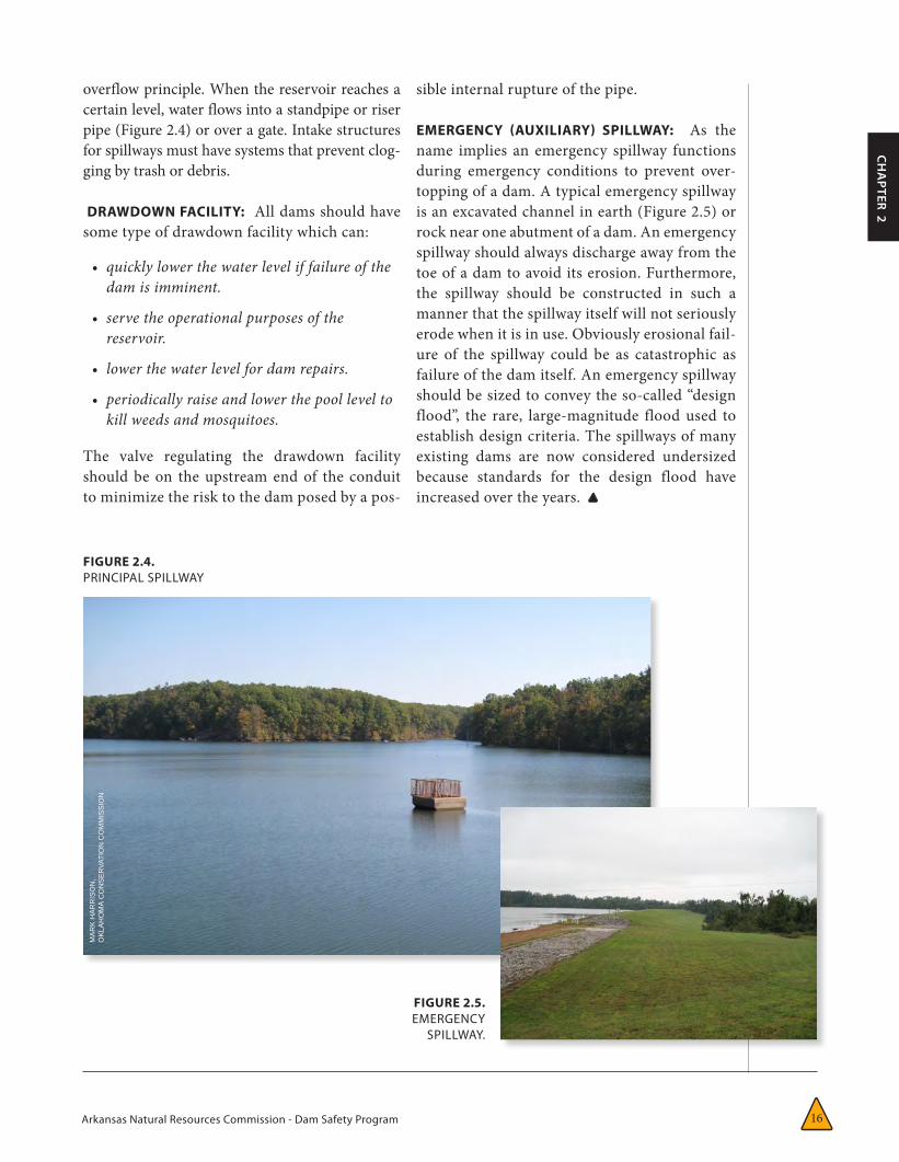
Arkansas Natural Resources Commission - Dam Safety Program 16
CH
APTER 2
overflow principle. When the reservoir reaches a certain level, water flows into a standpipe or riser pipe (Figure 2.4) or over a gate. Intake structures for spillways must have systems that prevent clog-ging by trash or debris.
DRAWDOWN FACILITY: All dams should have some type of drawdown facility which can:
• quicklylowerthewaterleveliffailureofthedamisimminent.
• servetheoperationalpurposesofthereservoir.
• lowerthewaterlevelfordamrepairs.
• periodicallyraiseandlowerthepoolleveltokillweedsandmosquitoes.
The valve regulating the drawdown facility should be on the upstream end of the conduit to minimize the risk to the dam posed by a pos-
sible internal rupture of the pipe.
EMERGENCY (AUXILIARY) SPILLWAY: As the name implies an emergency spillway functions during emergency conditions to prevent over-topping of a dam. A typical emergency spillway is an excavated channel in earth (Figure 2.5) or rock near one abutment of a dam. An emergency spillway should always discharge away from the toe of a dam to avoid its erosion. Furthermore, the spillway should be constructed in such a manner that the spillway itself will not seriously erode when it is in use. Obviously erosional fail-ure of the spillway could be as catastrophic as failure of the dam itself. An emergency spillway should be sized to convey the so-called “design flood”, the rare, large-magnitude flood used to establish design criteria. The spillways of many existing dams are now considered undersized because standards for the design flood have increased over the years.
FIGURE 2.4. PRINCIPAL SPILLWAY
FIGURE 2.5. EMERGENCY
SPILLWAY.
MA
RK
HA
RR
ISO
N,
OKLA
HOMA
CO
NS
ER
VATI
ON
CO
MM
ISS
ION
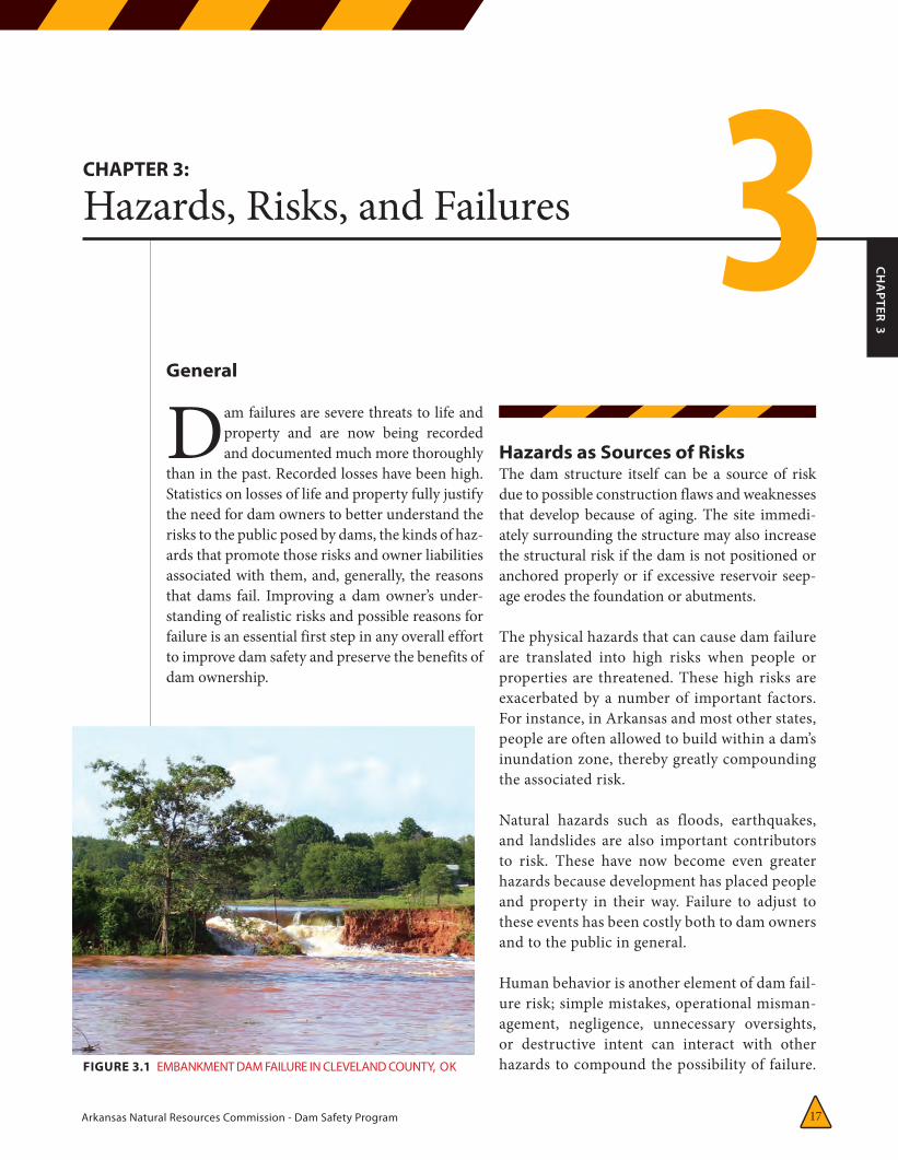
Arkansas Natural Resources Commission - Dam Safety Program 17
CH
APTER 3
CHAPTER 3:
Hazards, Risks, and Failures 3General
Dam failures are severe threats to life and property and are now being recorded and documented much more thoroughly
than in the past. Recorded losses have been high. Statistics on losses of life and property fully justify the need for dam owners to better understand the risks to the public posed by dams, the kinds of haz-ards that promote those risks and owner liabilities associated with them, and, generally, the reasons that dams fail. Improving a dam owner’s under-standing of realistic risks and possible reasons for failure is an essential first step in any overall effort to improve dam safety and preserve the benefits of dam ownership.
Hazards as Sources of RisksThe dam structure itself can be a source of risk due to possible construction flaws and weaknesses that develop because of aging. The site immedi-ately surrounding the structure may also increase the structural risk if the dam is not positioned or anchored properly or if excessive reservoir seep-age erodes the foundation or abutments.
The physical hazards that can cause dam failure are translated into high risks when people or properties are threatened. These high risks are exacerbated by a number of important factors. For instance, in Arkansas and most other states, people are often allowed to build within a dam’s inundation zone, thereby greatly compounding the associated risk.
Natural hazards such as floods, earthquakes, and landslides are also important contributors to risk. These have now become even greater hazards because development has placed people and property in their way. Failure to adjust to these events has been costly both to dam owners and to the public in general.
Human behavior is another element of dam fail-ure risk; simple mistakes, operational misman-agement, negligence, unnecessary oversights, or destructive intent can interact with other hazards to compound the possibility of failure. FIGURE 3.1 EMBANKMENT DAM FAILURE IN CLEVELAND COUNTY, OK
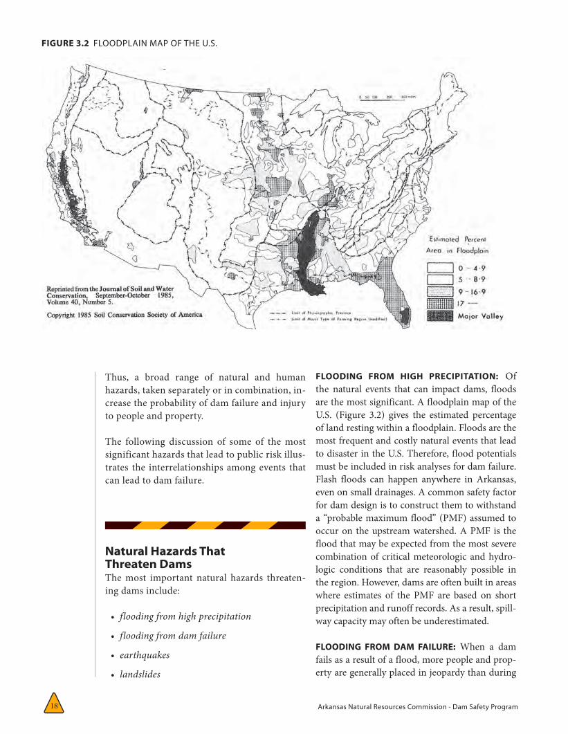
Arkansas Natural Resources Commission - Dam Safety Program 18
FLOODING FROM HIGH PRECIPITATION: Of the natural events that can impact dams, floods are the most significant. A floodplain map of the U.S. (Figure 3.2) gives the estimated percentage of land resting within a floodplain. Floods are the most frequent and costly natural events that lead to disaster in the U.S. Therefore, flood potentials must be included in risk analyses for dam failure. Flash floods can happen anywhere in Arkansas, even on small drainages. A common safety factor for dam design is to construct them to withstand a “probable maximum flood” (PMF) assumed to occur on the upstream watershed. A PMF is the flood that may be expected from the most severe combination of critical meteorologic and hydro-logic conditions that are reasonably possible in the region. However, dams are often built in areas where estimates of the PMF are based on short precipitation and runoff records. As a result, spill-way capacity may often be underestimated.
FLOODING FROM DAM FAILURE: When a dam fails as a result of a flood, more people and prop-erty are generally placed in jeopardy than during
Thus, a broad range of natural and human hazards, taken separately or in combination, in-crease the probability of dam failure and injury to people and property.
The following discussion of some of the most significant hazards that lead to public risk illus-trates the interrelationships among events that can lead to dam failure.
Natural Hazards That Threaten DamsThe most important natural hazards threaten-ing dams include:
• floodingfromhighprecipitation
• floodingfromdamfailure
• earthquakes
• landslides
FIGURE 3.2 FLOODPLAIN MAP OF THE U.S.
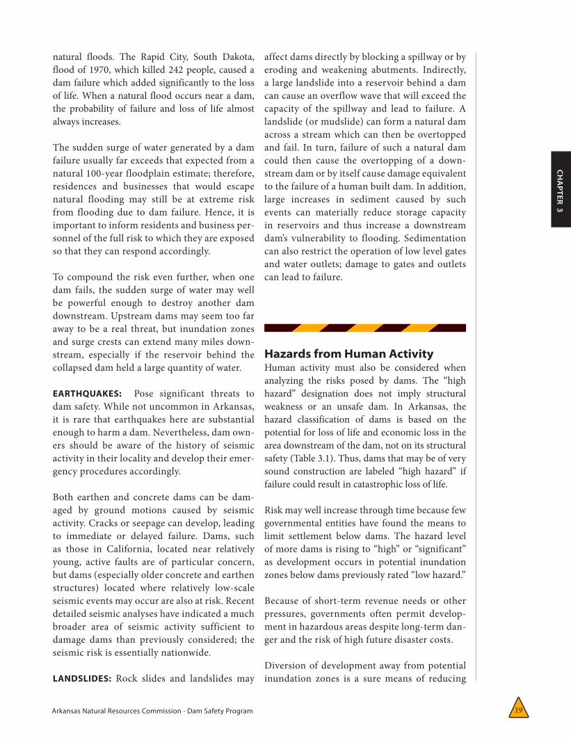
Arkansas Natural Resources Commission - Dam Safety Program 19
CH
APTER 3
natural floods. The Rapid City, South Dakota, flood of 1970, which killed 242 people, caused a dam failure which added significantly to the loss of life. When a natural flood occurs near a dam, the probability of failure and loss of life almost always increases.
The sudden surge of water generated by a dam failure usually far exceeds that expected from a natural 100-year floodplain estimate; therefore, residences and businesses that would escape natural flooding may still be at extreme risk from flooding due to dam failure. Hence, it is important to inform residents and business per-sonnel of the full risk to which they are exposed so that they can respond accordingly.
To compound the risk even further, when one dam fails, the sudden surge of water may well be powerful enough to destroy another dam downstream. Upstream dams may seem too far away to be a real threat, but inundation zones and surge crests can extend many miles down-stream, especially if the reservoir behind the collapsed dam held a large quantity of water.
EARTHQUAKES: Pose significant threats to dam safety. While not uncommon in Arkansas, it is rare that earthquakes here are substantial enough to harm a dam. Nevertheless, dam own-ers should be aware of the history of seismic activity in their locality and develop their emer-gency procedures accordingly.
Both earthen and concrete dams can be dam-aged by ground motions caused by seismic activity. Cracks or seepage can develop, leading to immediate or delayed failure. Dams, such as those in California, located near relatively young, active faults are of particular concern, but dams (especially older concrete and earthen structures) located where relatively low-scale seismic events may occur are also at risk. Recent detailed seismic analyses have indicated a much broader area of seismic activity sufficient to damage dams than previously considered; the seismic risk is essentially nationwide.
LANDSLIDES: Rock slides and landslides may
affect dams directly by blocking a spillway or by eroding and weakening abutments. Indirectly, a large landslide into a reservoir behind a dam can cause an overflow wave that will exceed the capacity of the spillway and lead to failure. A landslide (or mudslide) can form a natural dam across a stream which can then be overtopped and fail. In turn, failure of such a natural dam could then cause the overtopping of a down-stream dam or by itself cause damage equivalent to the failure of a human built dam. In addition, large increases in sediment caused by such events can materially reduce storage capacity in reservoirs and thus increase a downstream dam’s vulnerability to flooding. Sedimentation can also restrict the operation of low level gates and water outlets; damage to gates and outlets can lead to failure.
Hazards from Human ActivityHuman activity must also be considered when analyzing the risks posed by dams. The “high hazard” designation does not imply structural weakness or an unsafe dam. In Arkansas, the hazard classification of dams is based on the potential for loss of life and economic loss in the area downstream of the dam, not on its structural safety (Table 3.1). Thus, dams that may be of very sound construction are labeled “high hazard” if failure could result in catastrophic loss of life.
Risk may well increase through time because few governmental entities have found the means to limit settlement below dams. The hazard level of more dams is rising to “high” or “significant” as development occurs in potential inundation zones below dams previously rated “low hazard.”
Because of short-term revenue needs or other pressures, governments often permit develop-ment in hazardous areas despite long-term dan-ger and the risk of high future disaster costs.
Diversion of development away from potential inundation zones is a sure means of reducing
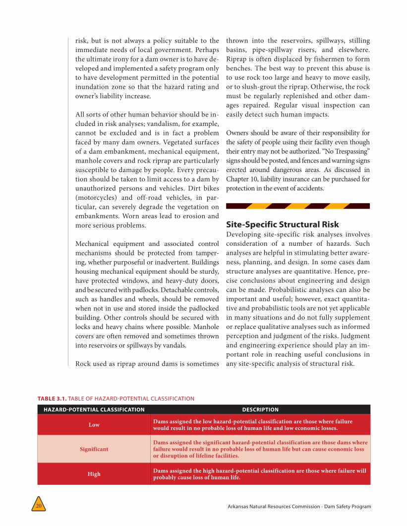
Arkansas Natural Resources Commission - Dam Safety Program 20
risk, but is not always a policy suitable to the immediate needs of local government. Perhaps the ultimate irony for a dam owner is to have de-veloped and implemented a safety program only to have development permitted in the potential inundation zone so that the hazard rating and owner’s liability increase.
All sorts of other human behavior should be in-cluded in risk analyses; vandalism, for example, cannot be excluded and is in fact a problem faced by many dam owners. Vegetated surfaces of a dam embankment, mechanical equipment, manhole covers and rock riprap are particularly susceptible to damage by people. Every precau-tion should be taken to limit access to a dam by unauthorized persons and vehicles. Dirt bikes (motorcycles) and off-road vehicles, in par-ticular, can severely degrade the vegetation on embankments. Worn areas lead to erosion and more serious problems.
Mechanical equipment and associated control mechanisms should be protected from tamper-ing, whether purposeful or inadvertent. Buildings housing mechanical equipment should be sturdy, have protected windows, and heavy-duty doors, and be secured with padlocks. Detachable controls, such as handles and wheels, should be removed when not in use and stored inside the padlocked building. Other controls should be secured with locks and heavy chains where possible. Manhole covers are often removed and sometimes thrown into reservoirs or spillways by vandals.
Rock used as riprap around dams is sometimes
thrown into the reservoirs, spillways, stilling basins, pipe-spillway risers, and elsewhere. Riprap is often displaced by fishermen to form benches. The best way to prevent this abuse is to use rock too large and heavy to move easily, or to slush-grout the riprap. Otherwise, the rock must be regularly replenished and other dam-ages repaired. Regular visual inspection can easily detect such human impacts.
Owners should be aware of their responsibility for the safety of people using their facility even though their entry may not be authorized. “No Trespassing” signs should be posted, and fences and warning signs erected around dangerous areas. As discussed in Chapter 10, liability insurance can be purchased for protection in the event of accidents.
Site-Specific Structural RiskDeveloping site-specific risk analyses involves consideration of a number of hazards. Such analyses are helpful in stimulating better aware-ness, planning, and design. In some cases dam structure analyses are quantitative. Hence, pre-cise conclusions about engineering and design can be made. Probabilistic analyses can also be important and useful; however, exact quantita-tive and probabilistic tools are not yet applicable in many situations and do not fully supplement or replace qualitative analyses such as informed perception and judgment of the risks. Judgment and engineering experience should play an im-portant role in reaching useful conclusions in any site-specific analysis of structural risk.
TABLE 3.1. TABLE OF HAZARD-POTENTIAL CLASSIFICATION
HAZARD-POTENTIAL CLASSIFICATION DESCRIPTION
Low Dams assigned the low hazard-potential classification are those where failure would result in no probable loss of human life and low economic losses.
SignificantDams assigned the significant hazard-potential classification are those dams where failure would result in no probable loss of human life but can cause economic loss or disruption of lifeline facilities.
High Dams assigned the high hazard-potential classification are those where failure will probably cause loss of human life.
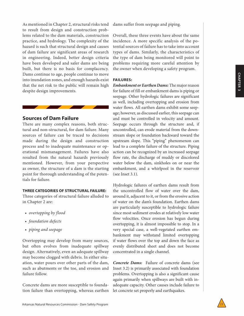
Arkansas Natural Resources Commission - Dam Safety Program 21
CH
APTER 3
As mentioned in Chapter 2, structural risks tend to result from design and construction prob-lems related to the dam materials, construction practice, and hydrology. The complexity of the hazard is such that structural design and causes of dam failure are significant areas of research in engineering. Indeed, better design criteria have been developed and safer dams are being built, but there is no basis for complacency. Dams continue to age, people continue to move into inundation zones, and enough hazards exist that the net risk to the public will remain high despite design improvements.
Sources of Dam FailureThere are many complex reasons, both struc-tural and non-structural, for dam failure. Many sources of failure can be traced to decisions made during the design and construction process and to inadequate maintenance or op-erational mismanagement. Failures have also resulted from the natural hazards previously mentioned. However, from your perspective as owner, the structure of a dam is the starting point for thorough understanding of the poten-tials for failure.
THREE CATEGORIES OF STRUCTURAL FAILURE:Three categories of structural failure alluded to in Chapter 2 are:
• overtoppingbyflood
• foundationdefects
• pipingandseepage
Overtopping may develop from many sources, but often evolves from inadequate spillway design. Alternatively, even an adequate spillway may become clogged with debris. In either situ-ation, water pours over other parts of the dam, such as abutments or the toe, and erosion and failure follow.
Concrete dams are more susceptible to founda-tion failure than overtopping, whereas earthen
dams suffer from seepage and piping.
Overall, these three events have about the same incidence. A more specific analysis of the po-tential sources of failure has to take into account types of dams. Similarly, the characteristics of the type of dam being monitored will point to problems requiring more careful attention by the owner when developing a safety program.
FAILURES: Embankment or Earthen Dams:The major reason for failure of fill or embankment dams is piping or seepage. Other hydrologic failures are significant as well, including overtopping and erosion from water flows. All earthen dams exhibit some seep-age; however, as discussed earlier, this seepage can and must be controlled in velocity and amount. Seepage occurs through the structure and, if uncontrolled, can erode material from the down-stream slope or foundation backward toward the upstream slope. This “piping” phenomenon can lead to a complete failure of the structure. Piping action can be recognized by an increased seepage flow rate, the discharge of muddy or discolored water below the dam, sinkholes on or near the embankment, and a whirlpool in the reservoir (see Inset 3.1).
Hydrologic failures of earthen dams result from the uncontrolled flow of water over the dam, around it, adjacent to it, or from the erosive action of water on the dam’s foundation. Earthen dams are particularly susceptible to hydrologic failure since most sediment erodes at relatively low water flow velocities. Once erosion has begun during overtopping, it is almost impossible to stop. In a very special case, a well-vegetated earthen em-bankment may withstand limited overtopping if water flows over the top and down the face as evenly distributed sheet and does not become concentrated in a single channel.
Concrete Dams: Failure of concrete dams (see Inset 3.2) is primarily associated with foundation problems. Overtopping is also a significant cause again primarily when spillways are built with in-adequate capacity. Other causes include failure to let concrete set properly and earthquakes.
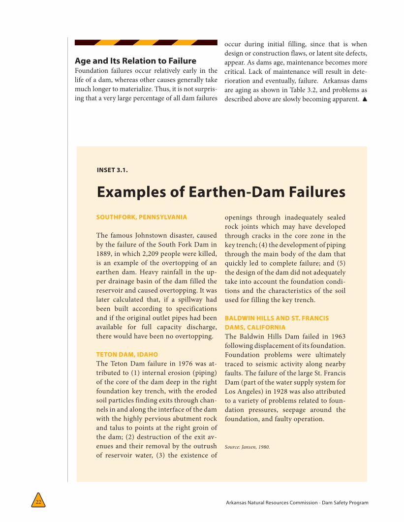
Arkansas Natural Resources Commission - Dam Safety Program 22
Age and Its Relation to FailureFoundation failures occur relatively early in the life of a dam, whereas other causes generally take much longer to materialize. Thus, it is not surpris-ing that a very large percentage of all dam failures
occur during initial filling, since that is when design or construction flaws, or latent site defects, appear. As dams age, maintenance becomes more critical. Lack of maintenance will result in dete-rioration and eventually, failure. Arkansas dams are aging as shown in Table 3.2, and problems as described above are slowly becoming apparent.
INSET 3.1.
Examples of Earthen-Dam FailuresSOUTHFORK, PENNSYLVANIA
The famous Johnstown disaster, caused by the failure of the South Fork Dam in 1889, in which 2,209 people were killed, is an example of the overtopping of an earthen dam. Heavy rainfall in the up-per drainage basin of the dam filled the reservoir and caused overtopping. It was later calculated that, if a spillway had been built according to specifications and if the original outlet pipes had been available for full capacity discharge, there would have been no overtopping.
TETON DAM, IDAHOThe Teton Dam failure in 1976 was at-tributed to (1) internal erosion (piping) of the core of the dam deep in the right foundation key trench, with the eroded soil particles finding exits through chan-nels in and along the interface of the dam with the highly pervious abutment rock and talus to points at the right groin of the dam; (2) destruction of the exit av-enues and their removal by the outrush of reservoir water, (3) the existence of
openings through inadequately sealed rock joints which may have developed through cracks in the core zone in the key trench; (4) the development of piping through the main body of the dam that quickly led to complete failure; and (5) the design of the dam did not adequately take into account the foundation condi-tions and the characteristics of the soil used for filling the key trench.
BALDWIN HILLS AND ST. FRANCIS DAMS, CALIFORNIAThe Baldwin Hills Dam failed in 1963 following displacement of its foundation. Foundation problems were ultimately traced to seismic activity along nearby faults. The failure of the large St. Francis Dam (part of the water supply system for Los Angeles) in 1928 was also attributed to a variety of problems related to foun-dation pressures, seepage around the foundation, and faulty operation.
Source: Jansen, 1980.
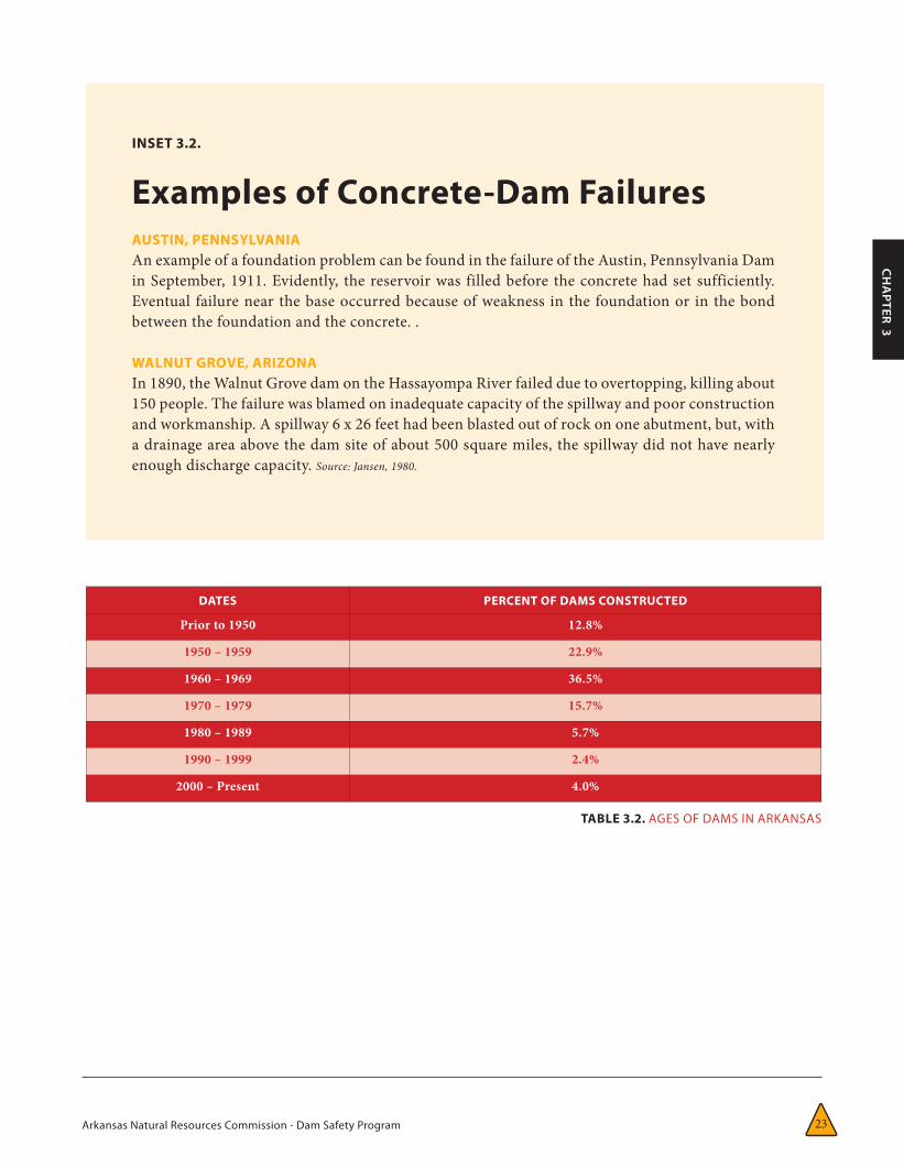
Arkansas Natural Resources Commission - Dam Safety Program 23
CH
APTER 3
INSET 3.2.
Examples of Concrete-Dam FailuresAUSTIN, PENNSYLVANIAAn example of a foundation problem can be found in the failure of the Austin, Pennsylvania Dam in September, 1911. Evidently, the reservoir was filled before the concrete had set sufficiently. Eventual failure near the base occurred because of weakness in the foundation or in the bond between the foundation and the concrete. .
WALNUT GROVE, ARIZONAIn 1890, the Walnut Grove dam on the Hassayompa River failed due to overtopping, killing about 150 people. The failure was blamed on inadequate capacity of the spillway and poor construction and workmanship. A spillway 6 x 26 feet had been blasted out of rock on one abutment, but, with a drainage area above the dam site of about 500 square miles, the spillway did not have nearly enough discharge capacity. Source: Jansen, 1980.
DATES PERCENT OF DAMS CONSTRUCTED
Prior to 1950 12.8%
1950 – 1959 22.9%
1960 – 1969 36.5%
1970 – 1979 15.7%
1980 – 1989 5.7%
1990 – 1999 2.4%
2000 – Present 4.0%
TABLE 3.2. AGES OF DAMS IN ARKANSAS

Arkansas Natural Resources Commission - Dam Safety Program 24
CH
APTER 4
Objectives of a Safety Program
The pressing issue of dam failure points up the need for a safety program. You, the owner, should base your program
on an evaluation of your dam’s structural and operational safety. Your program should iden-tify problems and recommend remedial repairs, operational restrictions and modifications, or further analyses and studies to determine solu-tions. Components of a safety program that address the spectrum of possible actions to be taken over the short and long-term include:
• assessingtheconditionofthedamanditscomponents
• conductingpreliminaryanddetailedinspections
• identifyingrepairsandcontinuingmaintenanceneeds
• establishingperiodicandcontinuousmonitoringcapabilitiesoverthelong-term
• establishinganemergencyactionplantohelpminimizeadverseimpactsshouldthedamfail
• establishingoperationsprocedureswhichrecognizedamfailurehazardsandrisks
• documentingthesafetyprogramsothattheinformationestablishedisavailableattimesofneedandcanbereadilyupdated
Develop your safety program in phases, begin-
CHAPTER 4:
Developing a Personal Safety Program4ning with collection and review of existing information, proceeding to detailed inspections and analyses, and culminating with formal documentation. You can accomplish much of the preliminary work personally, with the as-sistance of state and local agencies. However, depending upon the number and seriousness of problems identified by the initial assessment, you may require the professional assistance of qualified engineers and contractors.
Guidelines for Assessing Existing ConditionsThe guidelines for assessing existing conditions involve a sequence of steps that will enable you, the owner, to secure the information you will need to determine whether subsequent detailed investigations, repairs, and maintenance are required. The steps include:
• reviewingexistingdata
• visitingthesite
• inspectingthedam
• assessingsignificanceofobservedconditions
• decidingwhattodonext
REVIEWING EXISTING DATA: First and foremost, collect and review available information on the dam such as plans of its design, construction,
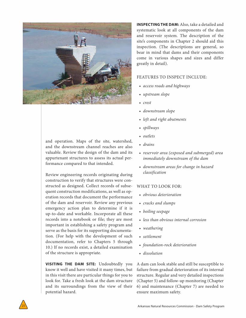
Arkansas Natural Resources Commission - Dam Safety Program25
and operation. Maps of the site, watershed, and the downstream channel reaches are also valuable. Review the design of the dam and its appurtenant structures to assess its actual per-formance compared to that intended.
Review engineering records originating during construction to verify that structures were con-structed as designed. Collect records of subse-quent construction modifications, as well as op-eration records that document the performance of the dam and reservoir. Review any previous emergency action plan to determine if it is up-to-date and workable. Incorporate all these records into a notebook or file; they are most important in establishing a safety program and serve as the basis for its supporting documenta-tion. (For help with the development of such documentation, refer to Chapters 5 through 10.) If no records exist, a detailed examination of the structure is appropriate.
VISITING THE DAM SITE: Undoubtedly you know it well and have visited it many times, but in this visit there are particular things for you to look for. Take a fresh look at the dam structure and its surroundings from the view of their potential hazard.
INSPECTING THE DAM: Also, take a detailed and systematic look at all components of the dam and reservoir system. The description of the site’s components in Chapter 2 should aid this inspection. (The descriptions are general, so bear in mind that dams and their components come in various shapes and sizes and differ greatly in detail).
FEATURES TO INSPECT INCLUDE:
• accessroadsandhighways
• upstreamslope
• crest
• downstreamslope
• leftandrightabutments
• spillways
• outlets
• drains
• reservoirarea(exposedandsubmerged)areaimmediatelydownstreamofthedam
• downstreamareasforchangeinhazardclassification
WHAT TO LOOK FOR:
• obviousdeterioration
• cracksandslumps
• boilingseepage
• lessthanobviousinternalcorrosion
• weathering
• settlement
• foundation-rockdeterioration
• dissolution
A dam can look stable and still be susceptible to failure from gradual deterioration of its internal structure. Regular and very detailed inspections (Chapter 5) and follow-up monitoring (Chapter 6) and maintenance (Chapter 7) are needed to ensure maximum safety.
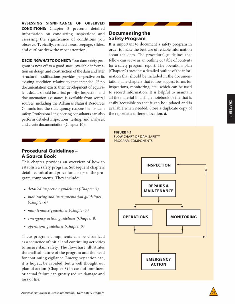
Arkansas Natural Resources Commission - Dam Safety Program 26
CH
APTER 4
ASSESSING SIGNIFICANCE OF OBSERVED CONDITIONS: Chapter 5 presents detailed information on conducting inspections and assessing the significance of conditions you observe. Typically, eroded areas, seepage, slides, and outflow draw the most attention.
DECIDING WHAT TO DO NEXT: Your dam safety pro-gram is now off to a good start. Available informa-tion on design and construction of the dam and later structural modifications provides perspective on its existing condition relative to that intended. If no documentation exists, then development of equiva-lent details should be a first priority. Inspection and documentation assistance is available from several sources, including the Arkansas Natural Resources Commission, the state agency responsible for dam safety. Professional engineering consultants can also perform detailed inspections, testing, and analyses, and create documentation (Chapter 10).
Procedural Guidelines – A Source BookThis chapter provides an overview of how to establish a safety program. Subsequent chapters detail technical and procedural steps of the pro-gram components. They include:
• detailedinspectionguidelines(Chapter5)
• monitoringandinstrumentationguidelines(Chapter6)
• maintenanceguidelines(Chapter7)
• emergencyactionguidelines(Chapter8)
• operationsguidelines(Chapter9)
These program components can be visualized as a sequence of initial and continuing activities to insure dam safety. The flowchart illustrates the cyclical nature of the program and the need for continuing vigilance. Emergency action can, it is hoped, be avoided, but a well thought out plan of action (Chapter 8) in case of imminent or actual failure can greatly reduce damage and loss of life.
FIGURE 4.1 FLOW CHART OF DAM SAFETY PROGRAM COMPONENTS
Documenting the Safety ProgramIt is important to document a safety program in order to make the best use of reliable information about the dam. The procedural guidelines that follow can serve as an outline or table of contents for a safety program report. The operations plan (Chapter 9) presents a detailed outline of the infor-mation that should be included in the documen-tation. The chapters that follow suggest forms for inspections, monitoring, etc., which can be used to record information. It is helpful to maintain all the material in a single notebook or file that is easily accessible so that it can be updated and is available when needed. Store a duplicate copy of the report at a different location.
INSPECTION
OPERATIONS MONITORING
REPAIRS & MAINTENANCE
EMERGENCYACTION

Arkansas Natural Resources Commission - Dam Safety Program 27
CH
APTER 5
CHAPTER 5:
Inspection Guidelines 5Introduction
An effective inspection program is essen-tial for identifying problems and pro-viding safe maintenance of a dam. An
inspection program should involve four types of inspections: (1) periodic technical inspec-tions; (2) periodic maintenance inspections; (3) downstream development inspections; (4) informal observations by project personnel as they operate the dam.
Technical inspections should be performed by professional engineers familiar with the design and construction of dams and should include assessments of structure safety.
Maintenance inspections are performed more frequently than technical inspections in order to detect, at an early stage, any developments that may be detrimental to the dam. They involve assessing operational capability as well as structural stability. Maintenance inspections are included as part of the more comprehensive technical inspection.
Downstream hazard verification inspections are performed by the dam owner to determine if there has been any construction of homes, buildings, or other structures downstream of their dam which could affect the hazard classification of their dam. This is a particular problem for low hazard-potential dams. If a house, other inhabited structure, or other construction is built downstream of a dam this could result in the need to reclassify to a higher hazard-potential class. This has important implications for the dam owner as it could result in a change how often the dam must be
inspected and require structural changes to the dam. Structural changes could include the amount of freeboard that must be maintained and the amount of water the spillway must be able to pass.
Informal inspections are actually a continuing effort by the dam owner’s on-site project personnel (dam tenders, powerhouse operators, maintenance workers) performed in the course of their normal duties.
The continued effectiveness of these inspections requires education of new personnel. Regular visual inspections are among the most economical means you, the owner, can use to ensure the safety and long life of your dam and its immediate environment. Visual inspection is a straightforward procedure that can be used by any properly trained person to make a reasonably accurate assessment of a dam’s condition.
Technical and maintenance inspections involve careful examination of the surface and all parts of the structure, including its adjacent environment, by a professional engineer. The equipment required is not expensive, and the inspection usually can be completed in less than one day (see Appendix A). Hazard verification and informal inspections can be performed by the dam owner or their operator. A dam owner, by applying the maximum prudent effort, can identify any changes in previously noted conditions that may indicate a safety problem. Quick, corrective action to conditions requiring attention will promote the safety and extend the useful life of your dam, while possibly preventing costly future repairs.
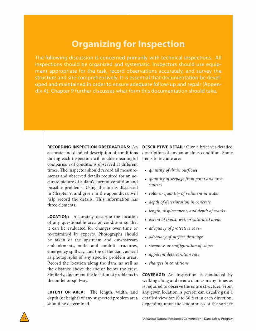
Arkansas Natural Resources Commission - Dam Safety Program28
RECORDING INSPECTION OBSERVATIONS: An accurate and detailed description of conditions during each inspection will enable meaningful comparison of conditions observed at different times. The inspector should record all measure-ments and observed details required for an ac-curate picture of a dam’s current condition and possible problems. Using the forms discussed in Chapter 9, and given in the appendices, will help record the details. This information has three elements:
LOCATION: Accurately describe the location of any questionable area or condition so that it can be evaluated for changes over time or re-examined by experts. Photographs should be taken of the upstream and downstream embankments, outlet and conduit structures, emergency spillway, and toe of the dam, as well as photographs of any specific problem areas. Record the location along the dam, as well as the distance above the toe or below the crest. Similarly, document the location of problems in the outlet or spillway.
EXTENT OR AREA: The length, width, and depth (or height) of any suspected problem area should be determined.
Organizing for InspectionThe following discussion is concerned primarily with technical inspections. All inspections should be organized and systematic. Inspectors should use equip-ment appropriate for the task, record observations accurately, and survey the structure and site comprehensively. It is essential that documentation be devel-oped and maintained in order to ensure adequate follow-up and repair (Appen-dix A). Chapter 9 further discusses what form this documentation should take.
DESCRIPTIVE DETAIL: Give a brief yet detailed description of any anomalous condition. Some items to include are:
• quantityofdrainoutflows
• quantityofseepagefrompointandareasources
• colororquantityofsedimentinwater
• depthofdeteriorationinconcrete
• length,displacement,anddepthofcracks
• extentofmoist,wet,orsaturatedareas
• adequacyofprotectivecover
• adequacyofsurfacedrainage
• steepnessorconfigurationofslopes
• apparentdeteriorationrate
• changesinconditions
COVERAGE: An inspection is conducted by walking along and over a dam as many times as is required to observe the entire structure. From any given location, a person can usually gain a detailed view for 10 to 30 feet in each direction, depending upon the smoothness of the surface
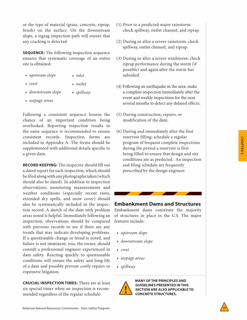
Arkansas Natural Resources Commission - Dam Safety Program 29
CH
APTER 5
or the type of material (grass, concrete, riprap, brush) on the surface. On the downstream slope, a zigzag inspection path will ensure that any cracking is detected.
SEQUENCE: The following inspection sequence ensures that systematic coverage of an entire site is obtained:
• upstreamslope
• crest
• downstreamslope
• seepageareas
Following a consistent sequence lessens the chance of an important condition being overlooked. Reporting inspection results in the same sequence is recommended to ensure consistent records. Inspection forms are included in Appendix A. The forms should be supplemented with additional details specific to a given dam.
RECORD KEEPING: The inspector should fill out a dated report for each inspection, which should be filed along with any photographs taken (which should also be dated). In addition to inspection observations, monitoring measurements and weather conditions (especially recent rains, extended dry spells, and snow cover) should also be systematically included in the inspec-tion record. A sketch of the dam with problem areas noted is helpful. Immediately following an inspection, observations should be compared with previous records to see if there are any trends that may indicate developing problems. If a questionable change or trend is noted, and failure is not imminent, you, the owner, should consult a professional engineer experienced in dam safety. Reacting quickly to questionable conditions will ensure the safety and long life of a dam and possibly prevent costly repairs or expensive litigation.
CRUCIAL INSPECTION TIMES: There are at least six special times when an inspection is recom-mended regardless of the regular schedule:
(1) Prior to a predicted major rainstorm: check spillway, outlet channel, and riprap.
(2) During or after a severe rainstorm: check
spillway, outlet channel, and riprap.
(3) During or after a severe windstorm: check riprap performance during the storm (if possible) and again after the storm has subsided.
(4) Following an earthquake in the area: make a complete inspection immediately after the event and weekly inspections for the next several months to detect any delayed effects.
(5) During construction, repairs, or modification of the dam.
(6) During and immediately after the first reservoir filling: schedule a regular program of frequent complete inspections during the period a reservoir is first being filled to ensure that design and site conditions are as predicted. An inspection and filing schedule are frequently prescribed by the design engineer.
Embankment Dams and StructuresEmbankment dams constitute the majority of structures in place in the U.S. The major features include:
• upstreamslope
• downstreamslope
• crest
• seepageareas
• spillway
MANY OF THE PRINCIPLES AND GUIDELINES PRESENTED IN THIS SECTION ARE ALSO APPLICABLE TO CONCRETE STRUCTURES.!
• inlet
• outlet
• spillway
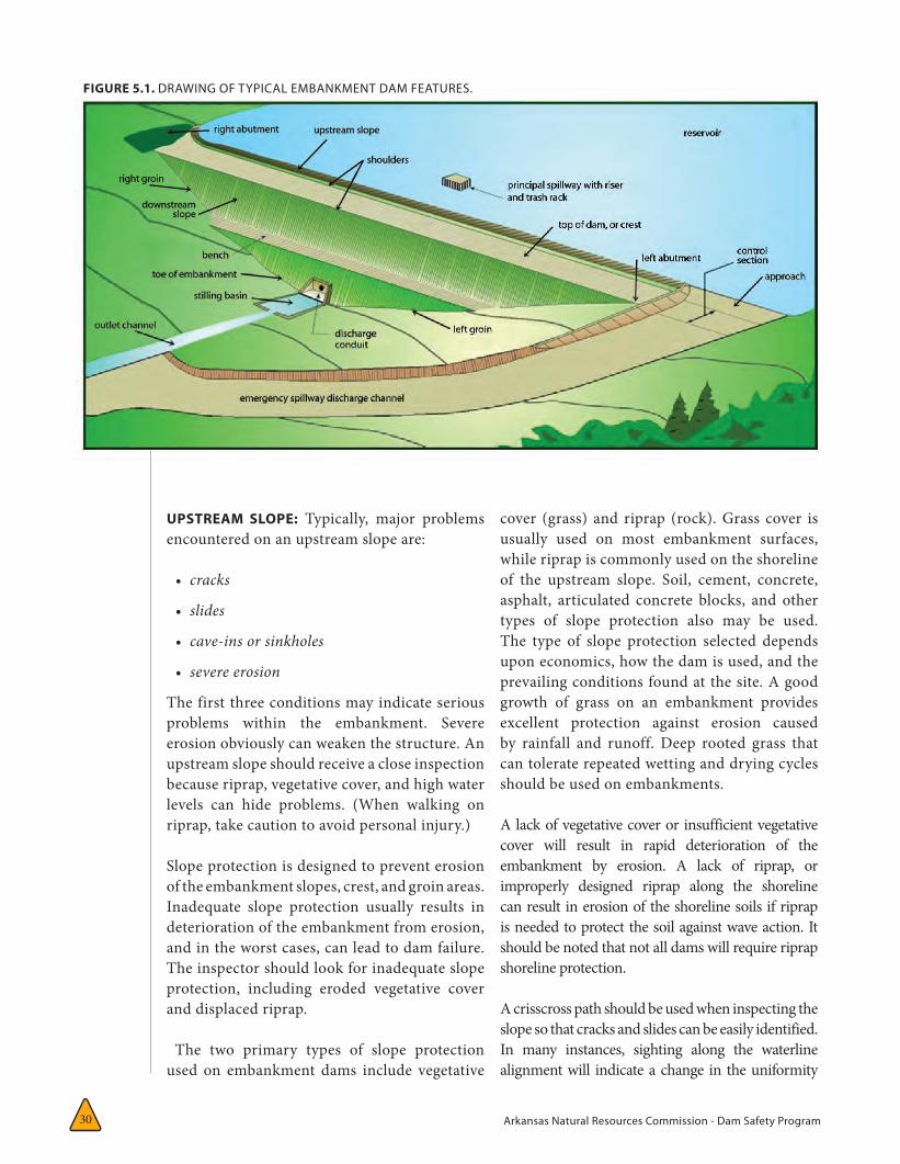
Arkansas Natural Resources Commission - Dam Safety Program30
UPSTREAM SLOPE: Typically, major problems encountered on an upstream slope are:
• cracks
• slides
• cave-insorsinkholes
• severeerosion
The first three conditions may indicate serious problems within the embankment. Severe erosion obviously can weaken the structure. An upstream slope should receive a close inspection because riprap, vegetative cover, and high water levels can hide problems. (When walking on riprap, take caution to avoid personal injury.)
Slope protection is designed to prevent erosion of the embankment slopes, crest, and groin areas. Inadequate slope protection usually results in deterioration of the embankment from erosion, and in the worst cases, can lead to dam failure. The inspector should look for inadequate slope protection, including eroded vegetative cover and displaced riprap.
The two primary types of slope protection used on embankment dams include vegetative
cover (grass) and riprap (rock). Grass cover is usually used on most embankment surfaces, while riprap is commonly used on the shoreline of the upstream slope. Soil, cement, concrete, asphalt, articulated concrete blocks, and other types of slope protection also may be used. The type of slope protection selected depends upon economics, how the dam is used, and the prevailing conditions found at the site. A good growth of grass on an embankment provides excellent protection against erosion caused by rainfall and runoff. Deep rooted grass that can tolerate repeated wetting and drying cycles should be used on embankments.
A lack of vegetative cover or insufficient vegetative cover will result in rapid deterioration of the embankment by erosion. A lack of riprap, or improperly designed riprap along the shoreline can result in erosion of the shoreline soils if riprap is needed to protect the soil against wave action. It should be noted that not all dams will require riprap shoreline protection.
A crisscross path should be used when inspecting the slope so that cracks and slides can be easily identified. In many instances, sighting along the waterline alignment will indicate a change in the uniformity
FIGURE 5.1. DRAWING OF TYPICAL EMBANKMENT DAM FEATURES.
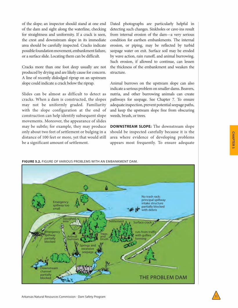
Arkansas Natural Resources Commission - Dam Safety Program 31
CH
APTER 5
of the slope; an inspector should stand at one end of the dam and sight along the waterline, checking for straightness and uniformity. If a crack is seen, the crest and downstream slope in its immediate area should be carefully inspected. Cracks indicate possible foundation movement, embankment failure, or a surface slide. Locating them can be difficult.
Cracks more than one foot deep usually are not produced by drying and are likely cause for concern. A line of recently dislodged riprap on an upstream slope could indicate a crack below the riprap.
Slides can be almost as difficult to detect as cracks. When a dam is constructed, the slopes may not be uniformly graded. Familiarity with the slope configuration at the end of construction can help identify subsequent slope movements. Moreover, the appearance of slides may be subtle; for example, they may produce only about two feet of settlement or bulging in a distance of 100 feet or more, yet that would still be a significant amount of settlement.
Dated photographs are particularly helpful in detecting such changes. Sinkholes or cave-ins result from internal erosion of the dam—a very serious condition for earthen embankments. The internal erosion, or piping, may be reflected by turbid seepage water on exit. Surface soil may be eroded by wave action, rain runoff, and animal burrowing. Such erosion, if allowed to continue, can lessen the thickness of the embankment and weaken the structure.
Animal burrows on the upstream slope can also indicate a serious problem on smaller dams. Beavers, nutria, and other burrowing animals can create pathways for seepage. See Chapter 7. To ensure adequate inspection, prevent potential seepage paths, and keep the upstream slope free from obscuring weeds, brush, or trees.
DOWNSTREAM SLOPE: The downstream slope should be inspected carefully because it is the area where evidence of developing problems appears most frequently. To ensure adequate
FIGURE 5.2. FIGURE OF VARIOUS PROBLEMS WITH AN EMBANKMENT DAM.
No trash rack: principal spillway intake structure partially blocked with debris
THE PROBLEM DAM
ruts from traffic with gullies forming
Surface crackSettlement
Treesand brush
Animal burrows
Emergency spillway too small
Emergency spillway partially blocked
Downstream channel partially blocked
Sloughed area
Springs and excessive seepage
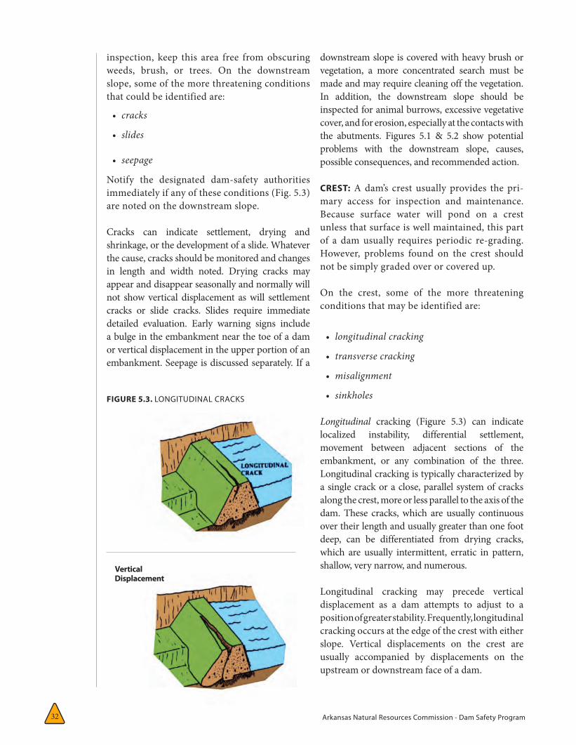
Arkansas Natural Resources Commission - Dam Safety Program32
inspection, keep this area free from obscuring weeds, brush, or trees. On the downstream slope, some of the more threatening conditions that could be identified are:
• cracks
• slides
• seepage
Notify the designated dam-safety authorities immediately if any of these conditions (Fig. 5.3) are noted on the downstream slope.
Cracks can indicate settlement, drying and shrinkage, or the development of a slide. Whatever the cause, cracks should be monitored and changes in length and width noted. Drying cracks may appear and disappear seasonally and normally will not show vertical displacement as will settlement cracks or slide cracks. Slides require immediate detailed evaluation. Early warning signs include a bulge in the embankment near the toe of a dam or vertical displacement in the upper portion of an embankment. Seepage is discussed separately. If a
downstream slope is covered with heavy brush or vegetation, a more concentrated search must be made and may require cleaning off the vegetation. In addition, the downstream slope should be inspected for animal burrows, excessive vegetative cover, and for erosion, especially at the contacts with the abutments. Figures 5.1 & 5.2 show potential problems with the downstream slope, causes, possible consequences, and recommended action.
CREST: A dam’s crest usually provides the pri-mary access for inspection and maintenance. Because surface water will pond on a crest unless that surface is well maintained, this part of a dam usually requires periodic re-grading. However, problems found on the crest should not be simply graded over or covered up.
On the crest, some of the more threatening conditions that may be identified are:
• longitudinalcracking
• transversecracking
• misalignment
• sinkholes
Longitudinal cracking (Figure 5.3) can indicate localized instability, differential settlement, movement between adjacent sections of the embankment, or any combination of the three. Longitudinal cracking is typically characterized by a single crack or a close, parallel system of cracks along the crest, more or less parallel to the axis of the dam. These cracks, which are usually continuous over their length and usually greater than one foot deep, can be differentiated from drying cracks, which are usually intermittent, erratic in pattern, shallow, very narrow, and numerous.
Longitudinal cracking may precede vertical displacement as a dam attempts to adjust to a position of greater stability. Frequently, longitudinal cracking occurs at the edge of the crest with either slope. Vertical displacements on the crest are usually accompanied by displacements on the upstream or downstream face of a dam.
Vertical Displacement
FIGURE 5.3. LONGITUDINAL CRACKS
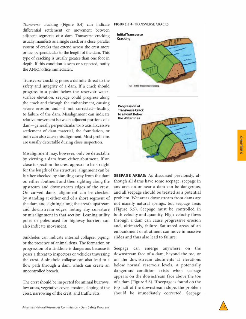
Arkansas Natural Resources Commission - Dam Safety Program 33
CH
APTER 5
Transverse cracking (Figure 5.4) can indicate differential settlement or movement between adjacent segments of a dam. Transverse cracking usually manifests as a single crack or a close, parallel system of cracks that extend across the crest more or less perpendicular to the length of the dam. This type of cracking is usually greater than one foot in depth. If this condition is seen or suspected, notify the ANRC office immediately.
Transverse cracking poses a definite threat to the safety and integrity of a dam. If a crack should progress to a point below the reservoir water-surface elevation, seepage could progress along the crack and through the embankment, causing severe erosion and—if not corrected—leading to failure of the dam. Misalignment can indicate relative movement between adjacent portions of a dam—generally perpendicular to its axis. Excessive settlement of dam material, the foundation, or both can also cause misalignment. Most problems are usually detectable during close inspection.
Misalignment may, however, only be detectable by viewing a dam from either abutment. If on close inspection the crest appears to be straight for the length of the structure, alignment can be further checked by standing away from the dam on either abutment and then sighting along the upstream and downstream edges of the crest. On curved dams, alignment can be checked by standing at either end of a short segment of the dam and sighting along the crest’s upstream and downstream edges, noting any curvature or misalignment in that section. Leaning utility poles or poles used for highway barriers can also indicate movement.
Sinkholes can indicate internal collapse, piping, or the presence of animal dens. The formation or progression of a sinkhole is dangerous because it poses a threat to inspectors or vehicles traversing the crest. A sinkhole collapse can also lead to a flow path through a dam, which can create an uncontrolled breach.
The crest should be inspected for animal burrows, low areas, vegetative cover, erosion, sloping of the crest, narrowing of the crest, and traffic ruts.
SEEPAGE AREAS: As discussed previously, al-though all dams have some seepage, seepage in any area on or near a dam can be dangerous, and all seepage should be treated as a potential problem. Wet areas downstream from dams are not usually natural springs, but seepage areas (Figure 5.5). Seepage must be controlled in both velocity and quantity. High-velocity flows through a dam can cause progressive erosion and, ultimately, failure. Saturated areas of an embankment or abutment can move in massive slides and thus also lead to failure.
Seepage can emerge anywhere on the downstream face of a dam, beyond the toe, or on the downstream abutments at elevations below normal reservoir levels. A potentially dangerous condition exists when seepage appears on the downstream face above the toe of a dam (Figure 5.6). If seepage is found on the top half of the downstream slope, the problem should be immediately corrected. Seepage
FIGURE 5.4. TRANSVERSE CRACKS.
Initial Transverse Cracking
Progression of Transverse Crack to a Point Below the Waterlines
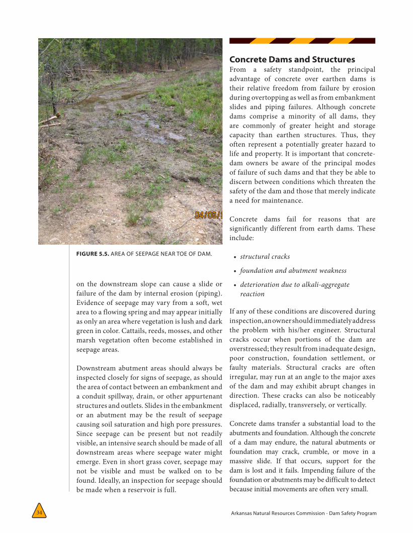
Arkansas Natural Resources Commission - Dam Safety Program34
on the downstream slope can cause a slide or failure of the dam by internal erosion (piping). Evidence of seepage may vary from a soft, wet area to a flowing spring and may appear initially as only an area where vegetation is lush and dark green in color. Cattails, reeds, mosses, and other marsh vegetation often become established in seepage areas.
Downstream abutment areas should always be inspected closely for signs of seepage, as should the area of contact between an embankment and a conduit spillway, drain, or other appurtenant structures and outlets. Slides in the embankment or an abutment may be the result of seepage causing soil saturation and high pore pressures. Since seepage can be present but not readily visible, an intensive search should be made of all downstream areas where seepage water might emerge. Even in short grass cover, seepage may not be visible and must be walked on to be found. Ideally, an inspection for seepage should be made when a reservoir is full.
Concrete Dams and StructuresFrom a safety standpoint, the principal advantage of concrete over earthen dams is their relative freedom from failure by erosion during overtopping as well as from embankment slides and piping failures. Although concrete dams comprise a minority of all dams, they are commonly of greater height and storage capacity than earthen structures. Thus, they often represent a potentially greater hazard to life and property. It is important that concrete-dam owners be aware of the principal modes of failure of such dams and that they be able to discern between conditions which threaten the safety of the dam and those that merely indicate a need for maintenance.
Concrete dams fail for reasons that are significantly different from earth dams. These include:
• structuralcracks
• foundationandabutmentweakness
• deteriorationduetoalkali-aggregatereaction
If any of these conditions are discovered during inspection, an owner should immediately address the problem with his/her engineer. Structural cracks occur when portions of the dam are overstressed; they result from inadequate design, poor construction, foundation settlement, or faulty materials. Structural cracks are often irregular, may run at an angle to the major axes of the dam and may exhibit abrupt changes in direction. These cracks can also be noticeably displaced, radially, transversely, or vertically.
Concrete dams transfer a substantial load to the abutments and foundation. Although the concrete of a dam may endure, the natural abutments or foundation may crack, crumble, or move in a massive slide. If that occurs, support for the dam is lost and it fails. Impending failure of the foundation or abutments may be difficult to detect because initial movements are often very small.
FIGURE 5.5. AREA OF SEEPAGE NEAR TOE OF DAM.
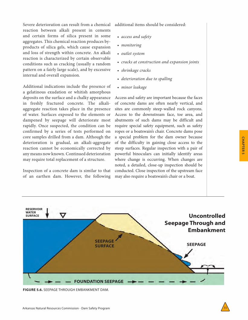
Arkansas Natural Resources Commission - Dam Safety Program 35
CH
APTER 5
Severe deterioration can result from a chemical reaction between alkali present in cements and certain forms of silica present in some aggregates. This chemical reaction produces by-products of silica gels, which cause expansion and loss of strength within concrete. An alkali reaction is characterized by certain observable conditions such as cracking (usually a random pattern on a fairly large scale), and by excessive internal and overall expansion.
Additional indications include the presence of a gelatinous exudation or whitish amorphous deposits on the surface and a chalky appearance in freshly fractured concrete. The alkali-aggregate reaction takes place in the presence of water. Surfaces exposed to the elements or dampened by seepage will deteriorate most rapidly. Once suspected, the condition can be confirmed by a series of tests performed on core samples drilled from a dam. Although the deterioration is gradual, an alkali-aggregate reaction cannot be economically corrected by any means now known. Continued deterioration may require total replacement of a structure.
Inspection of a concrete dam is similar to that of an earthen dam. However, the following
additional items should be considered:
• accessandsafety
• monitoring
• outletsystem
• cracksatconstructionandexpansionjoints
• shrinkagecracks
• deteriorationduetospalling
• minorleakage
Access and safety are important because the faces of concrete dams are often nearly vertical, and sites are commonly steep-walled rock canyons. Access to the downstream face, toe area, and abutments of such dams may be difficult and require special safety equipment, such as safety ropes or a boatswain’s chair. Concrete dams pose a special problem for the dam owner because of the difficulty in gaining close access to the steep surfaces. Regular inspection with a pair of powerful binoculars can initially identify areas where change is occurring. When changes are noted, a detailed, close-up inspection should be conducted. Close inspection of the upstream face may also require a boatswain’s chair or a boat.
FIGURE 5.6. SEEPAGE THROUGH EMBANKMENT DAM.
Uncontrolled Seepage Through and
Embankment
RESERVOIRWATER SURFACE
SEEPAGESURFACE
FOUNDATION SEEPAGE
SEEPAGE
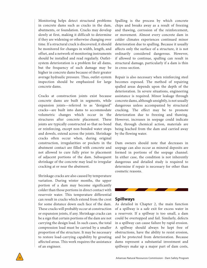
Arkansas Natural Resources Commission - Dam Safety Program36
Monitoring helps detect structural problems in concrete dams such as cracks in the dam, abutments, or foundation. Cracks may develop slowly at first, making it difficult to determine if they are widening or otherwise changing over time. If a structural crack is discovered, it should be monitored for changes in width, length, and offset, and a network of monitoring instruments should be installed and read regularly. Outlet-system deterioration is a problem for all dams, but the frequency of such damage may be higher in concrete dams because of their greater average hydraulic pressure. Thus, outlet-system inspection should be emphasized for large concrete dams.
Cracks at construction joints exist because concrete dams are built in segments, while expansion joints—referred to as “designed” cracks—are built into dams to accommodate volumetric changes which occur in the structures after concrete placement. These joints are typically constructed so that no bond or reinforcing, except non-bonded water stops and dowels, extend across the joints. Shrinkage cracks often occur when, during original construction, irregularities or pockets in the abutment contact are filled with concrete and not allowed to cure fully prior to placement of adjacent portions of the dam. Subsequent shrinkage of the concrete may lead to irregular cracking at or near the abutment.
Shrinkage cracks are also caused by temperature variation. During winter months, the upper portion of a dam may become significantly colder than those portions in direct contact with reservoir water. This temperature differential can result in cracks which extend from the crest for some distance down each face of the dam. These cracks will probably occur at construction or expansion joints, if any. Shrinkage cracks can be a sign that certain portions of the dam are not carrying the design load. In such cases, the total compression load must be carried by a smaller proportion of the structure. It may be necessary to restore load-carrying capability by grouting affected areas. This work requires the assistance of an engineer.
Spalling is the process by which concrete chips and breaks away as a result of freezing and thawing, corrosion of the reinforcement, or movement. Almost every concrete dam in colder climates experiences continued minor deterioration due to spalling. Because it usually affects only the surface of a structure, it is not ordinarily considered dangerous. However, if allowed to continue, spalling can result in structural damage, particularly if a dam is thin in cross-section.
Repair is also necessary when reinforcing steel becomes exposed. The method of repairing spalled areas depends upon the depth of the deterioration. In severe situations, engineering assistance is required. Minor leakage through concrete dams, although unsightly, is not usually dangerous unless accompanied by structural cracking. The effect may be to promote deterioration due to freezing and thawing. However, increases in seepage could indicate that, through chemical action, materials are being leached from the dam and carried away by the flowing water.
Dam owners should note that decreases in seepage can also occur as mineral deposits are formed in portions of the seepage channel. In either case, the condition is not inherently dangerous and detailed study is required to determine if repair is necessary for other than cosmetic reasons.
SpillwaysAs detailed in Chapter 2, the main function of a spillway is a safe exit for excess water in a reservoir. If a spillway is too small, a dam could be overtopped and fail. Similarly, defects in a spillway can cause failure by rapid erosion. A spillway should always be kept free of obstructions, have the ability to resist erosion, and be protected from deterioration. Because dams represent a substantial investment and spillways make up a major part of dam costs,
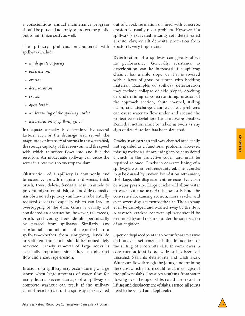
Arkansas Natural Resources Commission - Dam Safety Program 37
CH
APTER 5
a conscientious annual maintenance program should be pursued not only to protect the public but to minimize costs as well.
The primary problems encountered with spillways include:
• inadequatecapacity
• obstructions
• erosion
• deterioration
• cracks
• openjoints
• underminingofthespillwayoutlet
• deteriorationofspillwaygates
Inadequate capacity is determined by several factors, such as the drainage area served, the magnitude or intensity of storms in the watershed, the storage capacity of the reservoir, and the speed with which rainwater flows into and fills the reservoir. An inadequate spillway can cause the water in a reservoir to overtop the dam.
Obstruction of a spillway is commonly due to excessive growth of grass and weeds, thick brush, trees, debris, fences across channels to prevent migration of fish, or landslide deposits. An obstructed spillway can have a substantially reduced discharge capacity which can lead to overtopping of the dam. Grass is usually not considered an obstruction; however, tall weeds, brush, and young trees should periodically be cleared from spillways. Similarly, any substantial amount of soil deposited in a spillway—whether from sloughing, landslide or sediment transport—should be immediately removed. Timely removal of large rocks is especially important, since they can obstruct flow and encourage erosion.
Erosion of a spillway may occur during a large storm when large amounts of water flow for many hours. Severe damage of a spillway or complete washout can result if the spillway cannot resist erosion. If a spillway is excavated
out of a rock formation or lined with concrete, erosion is usually not a problem. However, if a spillway is excavated in sandy soil, deteriorated granite, clay, or silt deposits, protection from erosion is very important.
Deterioration of a spillway can greatly affect its performance. Generally, resistance to deterioration can be increased if a spillway channel has a mild slope, or if it is covered with a layer of grass or riprap with bedding material. Examples of spillway deterioration may include collapse of side slopes, cracking or undermining of concrete lining, erosion of the approach section, chute channel, stilling basin, and discharge channel. These problems can cause water to flow under and around the protective material and lead to severe erosion. Remedial action must be taken as soon as any sign of deterioration has been detected.
Cracks in an earthen spillway channel are usually not regarded as a functional problem. However, missing rocks in a riprap lining can be considered a crack in the protective cover, and must be repaired at once. Cracks in concrete lining of a spillway are commonly encountered. These cracks may be caused by uneven foundation settlement, shrinkage, slab displacement, or excessive earth or water pressure. Large cracks will allow water to wash out fine material below or behind the concrete slab, causing erosion, more cracks, and even severe displacement of the slab. The slab may even be dislodged and washed away by the flow. A severely cracked concrete spillway should be examined by and repaired under the supervision of an engineer.
Open or displaced joints can occur from excessive and uneven settlement of the foundation or the sliding of a concrete slab. In some cases, a construction joint is too wide or has been left unsealed. Sealants deteriorate and wash away. Water can flow through the joints, undermining the slabs, which in turn could result in collapse of the spillway slabs. Pressures resulting from water flowing over the open slabs could also result in lifting and displacement of slabs. Hence, all joints need to be sealed and kept sealed.
Arkansas Natural Resources Commission - Dam Safety Program38
Undermining of the spillway outlet is the erosion of foundation material and may weaken support and cause further cracks. Pressure induced by water flowing over displaced joints may wash away part of a wall or slab, or cause extensive undermining. Undermining of a spillway causes erosion at a spillway outlet, whether it is a pipe or overflow spillway, and is one of the most common spillway problems. Severe undermining of the outlet can displace sections of pipe, cause slides in the downstream embankment of the dam, and eventually lead to complete failure of a dam.
Water must be conveyed safely from the reservoir to a point downstream of the dam without endangering the spillway itself or the embankment. Often the spillway outlet is adequately protected for normal flow conditions, but not for extreme turbulent flows. It is easy to misestimate the energy and force of flowing water and the resistance of outlet material (earth, rock, concrete, etc). The required level of protection is difficult to establish by visual inspection but can usually be determined by hydraulic calculations performed by a professional engineer.
Structures that completely control erosion at a spillway outlet are usually expensive, but often necessary. Less expensive protection can also be effective, but require extensive periodic maintenance as areas of erosion and deterioration develop.
The following four factors, often interrelated, contribute to erosion at the spillway outlet:
1. Flows emerging from the outlet are above the stream channel. If outlet flows emerge at the correct elevation, tailwater in the stream channel can absorb a substantial amount of the high velocity. The flow and the hydraulic energy will be contained in the stilling basin.
2. Flows emerging from the spillway are generally free of sediment and therefore have substantial sediment-carrying
capacity. In taking on sediment, moving water will scour soil material from the channel and leave eroded areas. Such erosion is difficult to design for and requires protection of the outlet for a safe distance downstream from the dam.
3. Flows leaving the outlet at high velocity can create negative pressures that can cause material to come loose and separate from the floor and walls of the outlet channel. This process is called cavitation when it occurs on concrete or metal surfaces. Venting can sometimes be used to relieve negative pressures.
4. Water leaking through pipe joints or flowing along a pipe from the reservoir may weaken the soil structure around the pipe.
Inadequate compaction adjacent to such structures during construction can compound this problem. Deterioration of spillway gates can result in an inability of the gates to function during storm events. Causes of structural deterioration include, but are not limited to:
1. Corrosion can seriously weaken a structure or impair its operation. The effect of corrosion on the strength, stability, and serviceability of gates must be evaluated. A loss of cross section in a member causes a reduction in strength and stiffness that leads to increased stress levels and deformation without any change in the imposed loading. Flexure, shear, and buckling strength may be affected. A buildup of corrosion products can be damaging at connection details. For example, corrosion buildup in a tainter gate trunnion can lead to extremely high hoist loads. Localized pitting corrosion can form notches that may serve as fracture initiation sites, which could significantly reduce the member’s fatigue life.
2. Fracture usually initiates at a discontinuity that serves as a local stress raiser. Structural connections that are welded, bolted, or riveted are sources of discontinuities and stress concentrations.
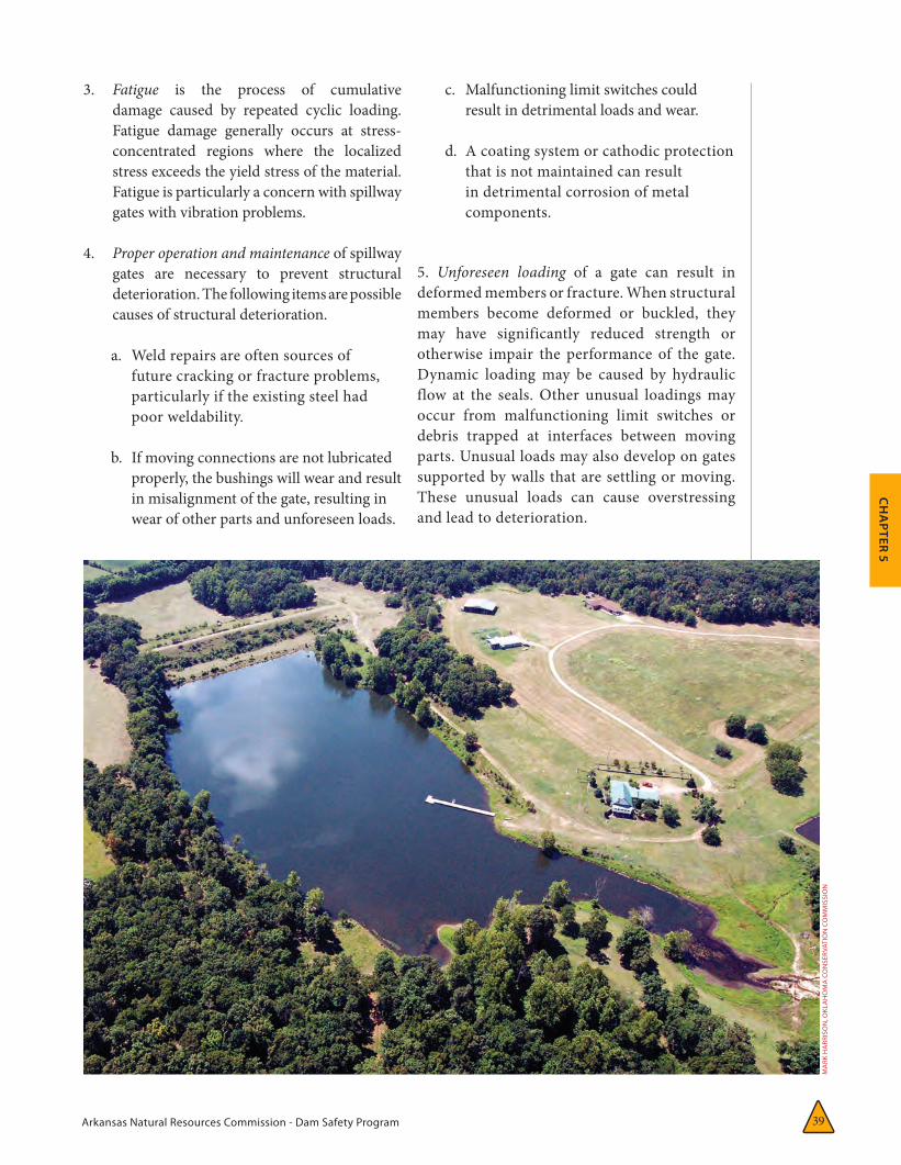
Arkansas Natural Resources Commission - Dam Safety Program 39
CH
APTER 5
3. Fatigue is the process of cumulative damage caused by repeated cyclic loading. Fatigue damage generally occurs at stress-concentrated regions where the localized stress exceeds the yield stress of the material. Fatigue is particularly a concern with spillway gates with vibration problems.
4. Proper operation and maintenance of spillway gates are necessary to prevent structural deterioration. The following items are possible causes of structural deterioration.
a. Weld repairs are often sources of future cracking or fracture problems, particularly if the existing steel had poor weldability.
b. If moving connections are not lubricated properly, the bushings will wear and result in misalignment of the gate, resulting in wear of other parts and unforeseen loads.
c. Malfunctioning limit switches could result in detrimental loads and wear.
d. A coating system or cathodic protection that is not maintained can result in detrimental corrosion of metal components.
5. Unforeseen loading of a gate can result in deformed members or fracture. When structural members become deformed or buckled, they may have significantly reduced strength or otherwise impair the performance of the gate. Dynamic loading may be caused by hydraulic flow at the seals. Other unusual loadings may occur from malfunctioning limit switches or debris trapped at interfaces between moving parts. Unusual loads may also develop on gates supported by walls that are settling or moving. These unusual loads can cause overstressing and lead to deterioration.
MA
RK H
ARR
ISO
N, O
KLAHOMA
CO
NSE
RVA
TIO
N C
OM
MIS
SIO
N
Arkansas Natural Resources Commission - Dam Safety Program4040
Procedure for Inspection of the SpillwaySpillway inspection is an important part of a dam safety program. Its basic objective is to detect any sign of obstruction, erosion, deterioration, misalignment, or cracking. An inspection of an earth spillway should determine whether side slopes have sloughed and whether there is excessive vegetation in the channel, and should look for signs of erosion and rodent activity. The inspector should also use a probe to determine the hardness and moisture content of the soil, note the location of particularly wet or soft spots, and see if the stilling basin or drop structure is properly protected with rocks or riprap. Because some erosion is unavoidable during spilling, an owner should also determine whether such erosion might endanger the embankment itself.
If the spillway is installed with a sill or wall, a dam owner should also determine if there are any cracks or misalignment in the sill or wall and check for erosion beneath the sill or wall or downstream from it. Hairline cracks are usu-ally harmless. Large cracks should be carefully inspected and their location, width, length, and orientation noted. Deterioration should be de-termined. The concrete should be examined for exposure of reinforcing bars.
Spillway surfaces exposed to freeze-thaw cycles often suffer from surface spalling. Chemical ac-tion, corrosion of the reinforcement, movement, contamination, and unsound aggregates can also cause spalling. If spalling is extensive, the spalled area should be sketched or photographed, show-ing its length, width, and depth. The problem should be examined closely to see if the remaining concrete has deteriorated or if reinforcing bars are exposed. The concrete should be tapped with a tapping device or rock hammer to determine if voids exist below the surface.
Shallow spalling should be examined from time to time to determine if it is becoming worse.
Deep spalling should be repaired as soon as possible by an experienced contractor.
Walls of spillways are usually equipped with weep (or drain) holes. Occasionally spillway chute slabs are also equipped with weep holes. If all such holes are dry, the soil behind the wall or below the slab is probably dry as well. If some holes are draining while others are dry, the dry holes may be plugged by mud or mineral deposits. Plugged weep holes increase the chances for failure of retaining walls or chute slabs. The plugged holes should be probed to determine causes of blockage, and soil or deposits cleaned out to restore drainage. If that work is not successful, rehabilitate the drain sys-tem as soon as possible under the supervision of a professional engineer.
Spillway retaining walls and chute slabs are normally constructed in sections. Between ad-joining sections, gaps or joints must be tightly sealed with flexible materials such as tar, epox-ies, or other chemical compounds. Sometimes rubber or plastic diaphragm materials or cop-per foil are used to obtain water tightness. Dur-ing inspection, one should note the location,
Arkansas Natural Resources Commission - Dam Safety Program 41
CH
APTER 5
length, and depth of any missing sealant, and probe open gaps to determine if soil behind the wall or below the slab has been undermined.
Misalignment of spillway retaining walls or chute slabs may be caused by foundation settlement or earth or water pressure. The inspector should carefully look at the upstream or downstream end of a spillway near the wall to determine if it has been tipped inward or outward. Relative displace-ment or offset between neighboring sections can be readily identified at joints. The horizontal as well as vertical displacement should be measured. A fence on top of the retaining wall is usually erected in a straight line at the time of construc-tion; thus any curve or distortion of the fence line may indicate wall deformation.
At the time of construction, the entire spillway chute should form a smooth surface. Thus, measurement of relative movement between neighboring chute slabs at joints will give a good indication of slab displacement. Misalignment or displacement of walls or the slab is often accompanied by cracks. A clear description of crack patterns should be recorded or photos taken to help in understanding the nature of the displacement.
THE FOLLOWING AREAS SHOULD BE IN-SPECTED ON ALL GATES IN SPILLWAYS:
• mainframingmembersandliftingandsupportassemblies
• locationssusceptibletofractureorweld-relatedcracking
• corrosion-susceptibleareas—normalwaterline,abrasionareas,crevices,areaswherewatercouldstand
• liftingconnectionsandchainsorcables
• trunnions
• intersectingwelds
• previouscracksrepairedbywelding
• locationsofpreviousrepairsorwheredamagehasbeenreported
• sealplates
Inlets, Outlets, and DrainsA dam’s inlet and outlet works, including internal drains, are essential to its operation.
Items for inspection and special attention include:
• reservoirpoollevels
• lakedrainsandinternaldrains
• corrosion
• trashracksonpipespillways
• cavitation
• areasongatesandspillwaysaslistedimmediatelyabove
Reservoir pool level drawdown should not exceed about 1 foot per week for slopes composed of clay or silt materials except in an emergency. Very flat slopes or slopes with free-draining upstream soils can, however, withstand more rapid drawdown rates. Pool levels can be controlled by spillway gates, drain-and-release structures, or flashboards. Flashboards, sometimes used to permanently or temporarily raise the pool level of water supply reservoirs, should not be installed or allowed unless there is sufficient freeboard remaining to safely accommodate a design flood
Conditions causing or requiring temporary or permanent adjustment of the pool level include:
• Aproblemthatrequiresloweringofthepool.Drawdownisatemporarysolutionuntiltheproblemissolved.
• Releaseofwaterdownstreamtosupplementstreamflowduringdryconditions.
• Fluctuationsintheservicearea’sdemandforwater.
• Repairofboatdocksinthewinterandgrowthofaquaticvegetationalongtheshoreline.
• Requirementsforrecreation,hydropower,orwaterfowlandfishmanagement.
!
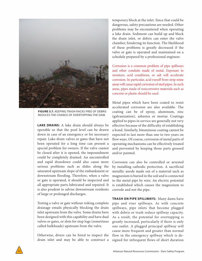
Arkansas Natural Resources Commission - Dam Safety Program42
LAKE DRAINS: A lake drain should always be operable so that the pool level can be drawn down in case of an emergency or for necessary repair. Lake-drain valves or gates that have not been operated for a long time can present a special problem for owners. If the valve cannot be closed after it is opened, the impoundment could be completely drained. An uncontrolled and rapid drawdown could also cause more serious problems such as slides along the saturated upstream slope of the embankment or downstream flooding. Therefore, when a valve or gate is operated, it should be inspected and all appropriate parts lubricated and repaired. It is also prudent to advise downstream residents of large or prolonged discharges.
Testing a valve or gate without risking complete drainage entails physically blocking the drain inlet upstream from the valve. Some drains have been designed with this capability and have dual valves or gates, or slots for stop logs (sometimes called bulkheads) upstream from the valve.
Otherwise, divers can be hired to inspect the drain inlet and may be able to construct a
temporary block at the inlet. Since that could be dangerous, safety precautions are needed. Other problems may be encountered when operating a lake drain. Sediment can build up and block the drain inlet, or debris can enter the valve chamber, hindering its function. The likelihood of these problems is greatly decreased if the valve or gate is operated and maintained on a schedule prepared by a professional engineer.
Corrosion is a common problem of pipe spillways and other conduits made of metal. Exposure to moisture, acid conditions, or salt will accelerate corrosion. In particular, acid runoff from strip mine areas will cause rapid corrosion of steel pipes. In such areas, pipes made of noncorrosive materials such as concrete or plastic should be used.
Metal pipes which have been coated to resist accelerated corrosion are also available. The coating can be of epoxy, aluminum, zinc (galvanization), asbestos or mortar. Coatings applied to pipes in service are generally not very effective because of the difficulty of establishing a bond. Similarly, bituminous coating cannot be expected to last more than one to two years on flow ways. Of course, corrosion of metal parts of operating mechanisms can be effectively treated and prevented by keeping those parts greased and/or painted.
Corrosion can also be controlled or arrested by installing cathodic protection. A sacrificial metallic anode made out of a material such as magnesium is buried in the soil and is connected to the metal pipe by wire. An electric potential is established which causes the magnesium to corrode and not the pipe.
TRASH ON PIPE SPILLWAYS: Many dams have pipe and riser spillways. As with concrete spillways, pipe inlets that become plugged with debris or trash reduce spillway capacity. As a result, the potential for overtopping is greatly increased, particularly if there is only one outlet. A plugged principal spillway will cause more frequent and greater than normal flow in the emergency spillway which is de-signed for infrequent flows of short duration
FIGURE 5.7. KEEPING TRASH RACKS FREE OF DEBRIS REDUCES THE CHANCE OF OVERTOPPING THE DAM.
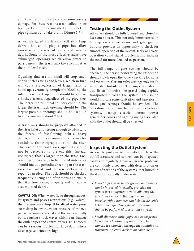
Arkansas Natural Resources Commission - Dam Safety Program 43
CH
APTER 5
and thus result in serious and unnecessary damage. For these reasons trash collectors or trash racks should be installed at the inlets to pipe spillways and lake drains (Figure 5.7).
A well-designed trash rack will stop large debris that could plug a pipe but allow unrestricted passage of water and smaller debris. Some of the most effective racks have submerged openings which allow water to pass beneath the trash into the riser inlet as the pool level rises.
Openings that are too small will stop small debris such as twigs and leaves, which in turn will cause a progression of larger items to build up, eventually completely blocking the inlet. Trash rack openings should be at least 6 inches across, regardless of the pipe size. The larger the principal spillway conduit, the larger the trash rack opening should be. The largest possible openings should be used, up to a maximum of about 2 feet.
A trash rack should be properly attached to the riser inlet and strong enough to withstand the forces of fast-flowing debris, heavy debris, and ice. It is a common occurrence for vandals to throw riprap stone into the riser. The size of the trash rack openings should not be decreased to prevent this. Instead, use riprap that is larger than the trash rack openings or too large to handle. Maintenance should include periodic checking of the trash rack for rusted and broken sections and repair as needed. The rack should be checked frequently during and after storms to ensure that it is functioning properly and to remove accumulated debris.
CAVITATION: When water flows through an out-let system and passes restrictions (e.g., valves), the pressure may drop. If localized water pres-sures drop below the vapor pressure of water, a partial vacuum is created and the water actually boils, causing shock-waves which can damage the outlet pipes and control valves. This process can be a serious problem for large dams where discharge velocities are high.
Testing the Outlet System All valves should be fully opened and closed at least once a year. This not only limits corrosion buildup on control stems and gate guides, but also provides an opportunity to check for smooth operation of the system. Jerky or erratic operation could signal problems, and indicate the need for more detailed inspection.
The full range of gate settings should be checked. The person performing the inspection should slowly open the valve, checking for noise and vibration. Certain valve settings may result in greater turbulence. The inspector should also listen for noise like gravel being rapidly transported through the system. This sound would indicate some cavitation and henceforth, those gate settings should be avoided. The operation of all mechanical and electrical systems, backup electric motors, power generators, power and lighting wiring associated with the outlet should all be checked.
Inspecting the Outlet System Accessible portions of the outlet, such as the outfall structure and control, can be inspected easily and regularly. However, severe problems are commonly associated with deterioration or failure of portions of the system either buried in the dam or normally under water.
• Outletpipes30inchesorgreaterindiametercanbeinspectedinternally,providedthesystemhasanupstreamvalveallowingthepipetobeemptied.Tappingtheconduitinteriorwithahammercanhelplocatevoidsbehindthepipe.Thistypeofinspectionshouldbeperformedatleastonceayear.
• Small-diameteroutletpipescanbeinspectedbyremoteTVcameraifnecessary.Thecameraischanneledthroughtheconduitandtransmitsapicturebacktoanequipment

Arkansas Natural Resources Commission - Dam Safety Program44
truck. This type of inspection is expensive and usually requires the services of an engineer. However, if no other method of inspection is possible, inspection by TV is recommended at least once every five years.
• Outletintakestructures,wetwells,andoutlet pipes with only downstream valves are the most difficult dam appurtenances to inspect because they are usually under water. These should be inspected whenever the reservoir is drawn down or at five-year intervals. If a definite problem is suspected, or if the reservoir remains full over extended periods, divers should be hired to perform an underwater inspection.
General AreasOther areas requiring inspection include:
• mechanicalandelectricalsystems
• thereservoirsurfaceandshoreline
• theupstreamwatershed
• downstreamfloodplains
Mechanical equipment includes spillway gates, sluice gates or valves for lake drains or water supply pipes, stop logs, sump pumps, flashboards, relief wells, emergency power sources, siphons, and other devices. All mechanical and associated electrical equipment should be operated at least once a year and preferably more often. The test should cover the full operating range of the equipment under actual operating conditions. Each operating device should be permanently marked for easy identification, and all operating equipment should be kept accessible. All controls should be checked for proper security to prevent vandalism or malicious intent, and finally, all operating instructions should be checked for clarity and maintained in a secure, but readily accessible, location.
The reservoir surface and shoreline should be inspected to identify possible problems away
from the actual structure. Whirlpools can indicate submerged outlets. Large landslides into the reservoir could cause waves to overtop the dam.
Floods arise from the upstream watershed. Therefore, characteristics of the watershed, such as impervious areas (e.g., parking lots), relate directly to the magnitude of a flood. Urban development in a watershed can increase the size of flood peaks and the volume of runoff, making a previously acceptable spillway inadequate.
Awareness of upstream development and other factors that might influence reservoir inflows is important in order to determine the necessity for any modifications to the dam or spillways. Development in downstream floodplains is also very important to the dam owner as the extent of development and flood preparedness relates directly to loss of life and damages should the dam fail. Downstream development may raise the hazard rating of the dam and therefore, should be accounted for during annual assessments.
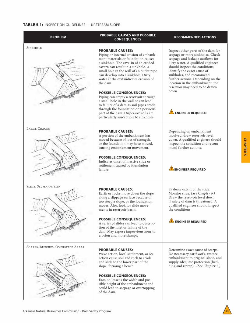
Arkansas Natural Resources Commission - Dam Safety Program 45
CH
APTER 5
TABLE 5.1: INSPECTION GUIDELINES — UPSTREAM SLOPE
PROBLEM PROBABLE CAUSES AND POSSIBLE CONSEQUENCES RECOMMENDED ACTIONS
SinkholePROBABLE CAUSES: Piping or internal erosion of embank-ment materials or foundation causes a sinkhole. The cave-in of an eroded cavern can result in a sinkhole. A small hole in the wall of an outlet pipe can develop into a sinkhole. Dirty water at the exit indicates erosion of the dam.
POSSIBLE CONSEQUENCES: Piping can empty a reservoir through a small hole in the wall or can lead to failure of a dam as soil pipes erode through the foundation or a pervious part of the dam. Dispersive soils are particularly susceptible to sinkholes.
Inspect other parts of the dam for seepage or more sinkholes. Check seepage and leakage outflows for dirty water. A qualified engineer should inspect the conditions, identify the exact cause of sinkholes, and recommend further actions. Depending on the location in the embankment, the reservoir may need to be drawn down.
! ENGINEER REQUIRED
Large CracksPROBABLE CAUSES: A portion of the embankment has moved because of loss of strength, or the foundation may have moved, causing embankment movement.
POSSIBLE CONSEQUENCES: Indicates onset of massive slide or settlement caused by foundation failure.
Depending on embankment involved, draw reservoir level down. A qualified engineer should inspect the condition and recom-mend further actions.
! ENGINEER REQUIRED
Slide, Slump, or SlipPROBABLE CAUSES: Earth or rocks move down the slope along a slippage surface because of too steep a slope, or the foundation moves. Also, look for slide move-ments in reservoir basin.
POSSIBLE CONSEQUENCES: A series of slides can lead to obstruc-tion of the inlet or failure of the dam. May expose impervious zone to erosion and more slumps.
Evaluate extent of the slide. Monitor slide. (See Chapter 6.) Draw the reservoir level down if safety of dam is threatened. A qualified engineer should inspect the conditions
! ENGINEER REQUIRED
Scarps, Benches, Oversteep AreasPROBABLE CAUSES: Wave action, local settlement, or ice action cause soil and rock to erode and slide to the lower part of the slope, forming a bench.
POSSIBLE CONSEQUENCES: Erosion lessens the width and pos-sible height of the embankment and could lead to seepage or overtopping of the dam.
Determine exact cause of scarps. Do necessary earthwork, restore embankment to original slope, and supply adequate protection (bed-ding and riprap). (See Chapter 7.)
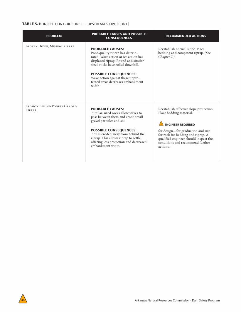
Arkansas Natural Resources Commission - Dam Safety Program46
TABLE 5.1: INSPECTION GUIDELINES — UPSTREAM SLOPE, (CONT.)
PROBLEM PROBABLE CAUSES AND POSSIBLE CONSEQUENCES RECOMMENDED ACTIONS
Broken Down, Missing RiprapPROBABLE CAUSES: Poor-quality riprap has deterio-rated. Wave action or ice action has displaced riprap. Round and similar-sized rocks have rolled downhill.
POSSIBLE CONSEQUENCES: Wave action against these unpro-tected areas decreases embankment width
Reestablish normal slope. Place bedding and competent riprap. (See Chapter 7.)
Erosion Behind Poorly Graded Riprap PROBABLE CAUSES:
Similar-sized rocks allow waves to pass between them and erode small gravel particles and soil.
POSSIBLE CONSEQUENCES: Soil is eroded away from behind the riprap. This allows riprap to settle, offering less protection and decreased embankment width.
Reestablish effective slope protection. Place bedding material.
! ENGINEER REQUIRED
for design—for graduation and size for rock for bedding and riprap. A qualified engineer should inspect the conditions and recommend further actions.
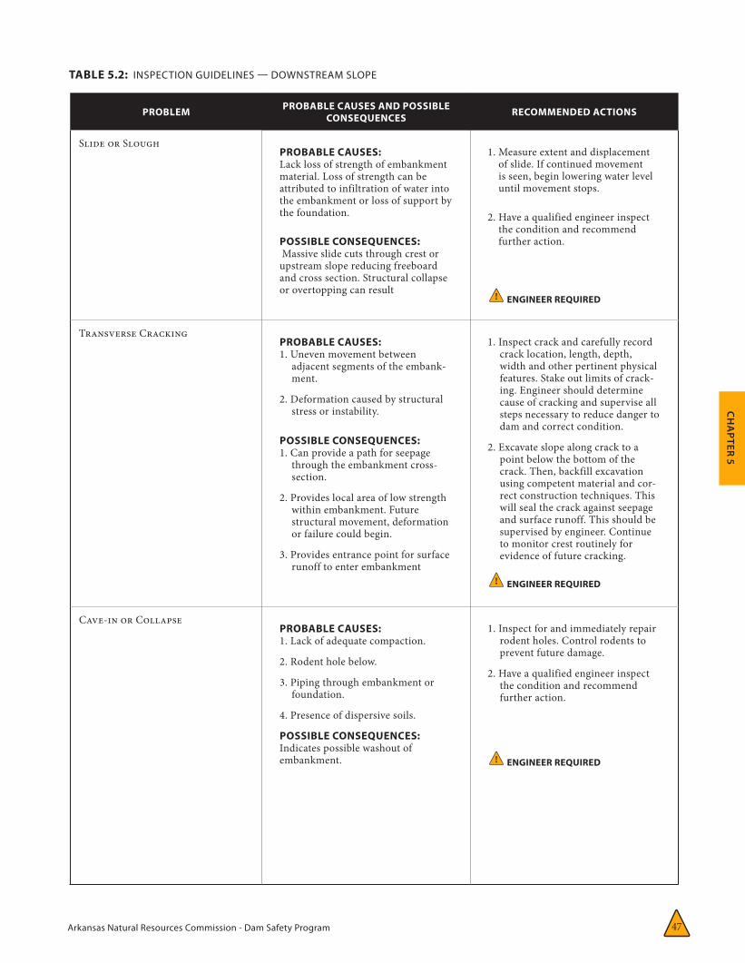
Arkansas Natural Resources Commission - Dam Safety Program 47
CH
APTER 5
TABLE 5.2: INSPECTION GUIDELINES — DOWNSTREAM SLOPE
PROBLEM PROBABLE CAUSES AND POSSIBLE CONSEQUENCES RECOMMENDED ACTIONS
Slide or SloughPROBABLE CAUSES: Lack loss of strength of embankment material. Loss of strength can be attributed to infiltration of water into the embankment or loss of support by the foundation.
POSSIBLE CONSEQUENCES: Massive slide cuts through crest or upstream slope reducing freeboard and cross section. Structural collapse or overtopping can result
1. Measure extent and displacement of slide. If continued movement is seen, begin lowering water level until movement stops.
2. Have a qualified engineer inspect the condition and recommend further action.
! ENGINEER REQUIRED
Transverse CrackingPROBABLE CAUSES: 1. Uneven movement between
adjacent segments of the embank-ment.
2. Deformation caused by structural stress or instability.
POSSIBLE CONSEQUENCES: 1. Can provide a path for seepage
through the embankment cross-section.
2. Provides local area of low strength within embankment. Future structural movement, deformation or failure could begin.
3. Provides entrance point for surface runoff to enter embankment
1. Inspect crack and carefully record crack location, length, depth, width and other pertinent physical features. Stake out limits of crack-ing. Engineer should determine cause of cracking and supervise all steps necessary to reduce danger to dam and correct condition.
2. Excavate slope along crack to a point below the bottom of the crack. Then, backfill excavation using competent material and cor-rect construction techniques. This will seal the crack against seepage and surface runoff. This should be supervised by engineer. Continue to monitor crest routinely for evidence of future cracking.
! ENGINEER REQUIRED
Cave-in or CollapsePROBABLE CAUSES: 1. Lack of adequate compaction.
2. Rodent hole below.
3. Piping through embankment or foundation.
4. Presence of dispersive soils.
POSSIBLE CONSEQUENCES: Indicates possible washout of embankment.
1. Inspect for and immediately repair rodent holes. Control rodents to prevent future damage.
2. Have a qualified engineer inspect the condition and recommend further action.
! ENGINEER REQUIRED
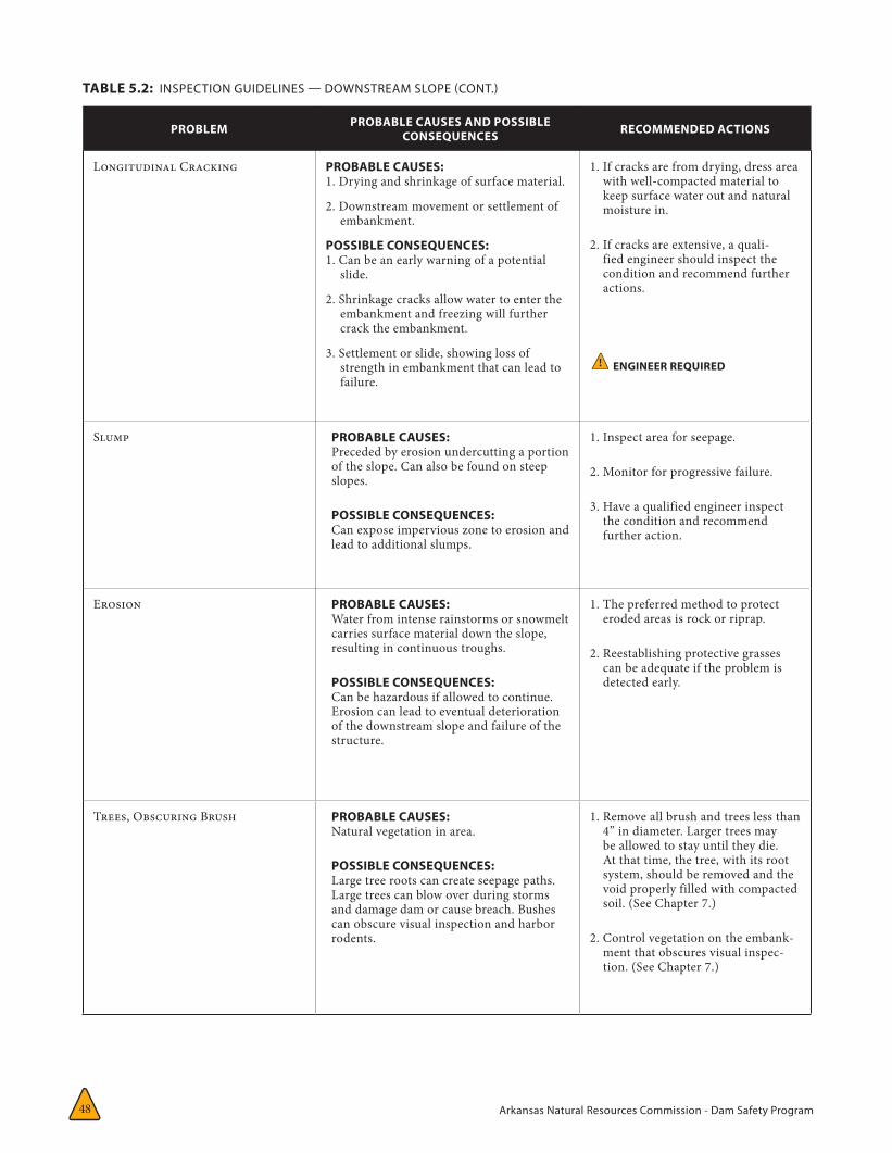
Arkansas Natural Resources Commission - Dam Safety Program48
TABLE 5.2: INSPECTION GUIDELINES — DOWNSTREAM SLOPE (CONT.)
PROBLEM PROBABLE CAUSES AND POSSIBLE CONSEQUENCES RECOMMENDED ACTIONS
Longitudinal Cracking PROBABLE CAUSES: 1. Drying and shrinkage of surface material.
2. Downstream movement or settlement of embankment.
POSSIBLE CONSEQUENCES: 1. Can be an early warning of a potential
slide.
2. Shrinkage cracks allow water to enter the embankment and freezing will further crack the embankment.
3. Settlement or slide, showing loss of strength in embankment that can lead to failure.
1. If cracks are from drying, dress area with well-compacted material to keep surface water out and natural moisture in.
2. If cracks are extensive, a quali-fied engineer should inspect the condition and recommend further actions.
! ENGINEER REQUIRED
Slump PROBABLE CAUSES: Preceded by erosion undercutting a portion of the slope. Can also be found on steep slopes.
POSSIBLE CONSEQUENCES: Can expose impervious zone to erosion and lead to additional slumps.
1. Inspect area for seepage.
2. Monitor for progressive failure.
3. Have a qualified engineer inspect the condition and recommend further action.
Erosion PROBABLE CAUSES: Water from intense rainstorms or snowmelt carries surface material down the slope, resulting in continuous troughs.
POSSIBLE CONSEQUENCES: Can be hazardous if allowed to continue. Erosion can lead to eventual deterioration of the downstream slope and failure of the structure.
1. The preferred method to protect eroded areas is rock or riprap.
2. Reestablishing protective grasses can be adequate if the problem is detected early.
Trees, Obscuring Brush PROBABLE CAUSES: Natural vegetation in area.
POSSIBLE CONSEQUENCES: Large tree roots can create seepage paths. Large trees can blow over during storms and damage dam or cause breach. Bushes can obscure visual inspection and harbor rodents.
1. Remove all brush and trees less than 4” in diameter. Larger trees may be allowed to stay until they die. At that time, the tree, with its root system, should be removed and the void properly filled with compacted soil. (See Chapter 7.)
2. Control vegetation on the embank-ment that obscures visual inspec-tion. (See Chapter 7.)

Arkansas Natural Resources Commission - Dam Safety Program 49
CH
APTER 5
PROBLEM PROBABLE CAUSES AND POSSIBLE CONSEQUENCES RECOMMENDED ACTIONS
Rodent Activity PROBABLE CAUSES: Overabundance of rodents. Animal burrowing creates holes, tunnels, and caverns. Certain habitats, such as cattail-filled areas and trees close to the reservoir encourage these animals.
POSSIBLE CONSEQUENCES: Can reduce length of seepage path and lead to piping failure. If tunnel runs through most of the dam, it can lead to collapse.
1. Control rodents to prevent more damage.
2. Backfill existing rodent holes.
3. Remove rodents. Determine exact location and extent of tunneling. Remove habitat and repair damages. (See Chapter 7.)
! ENGINEER REQUIRED
Livestock (such as cattle traffic)
PROBABLE CAUSES: Excessive travel by livestock especially harmful to slope when wet.
POSSIBLE CONSEQUENCES: Creates areas bare of erosion protection and causes erosion channels. Allows water to stand. Area susceptible to drying cracks.
1. Fence livestock outside embank-ment area.
2. Repair erosion protection, i.e. riprap, and grass.
TABLE 5.2: INSPECTION GUIDELINES — DOWNSTREAM SLOPE (CONT.)
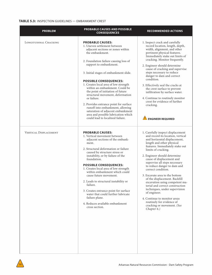
Arkansas Natural Resources Commission - Dam Safety Program50
TABLE 5.3: INSPECTION GUIDELINES — EMBANKMENT CREST
PROBLEM PROBABLE CAUSES AND POSSIBLE CONSEQUENCES RECOMMENDED ACTIONS
Longitudinal Cracking PROBABLE CAUSES: 1. Uneven settlement between
adjacent sections or zones within the embankment.
2. Foundation failure causing loss of support to embankment.
3. Initial stages of embankment slide.
POSSIBLE CONSEQUENCES: 1. Creates local area of low strength
within an embankment. Could be the point of initiation of future structural movement, deformation or failure.
2. Provides entrance point for surface runoff into embankment, allowing saturation of adjacent embankment area and possible lubrication which could lead to localized failure.
1. Inspect crack and carefully record location, length, depth, width, alignment, and other pertinent physical features. Immediately stake out limits of cracking. Monitor frequently.
2. Engineer should determine cause of cracking and supervise steps necessary to reduce danger to dam and correct condition.
3. Effectively seal the cracks at the crest surface to prevent infiltration by surface water.
4. Continue to routinely monitor crest for evidence of further cracking.
! ENGINEER REQUIRED
Vertical Displacement PROBABLE CAUSES: 1. Vertical movement between
adjacent sections of the embank-ment.
2. Structural deformation or failure caused by structure stress or instability, or by failure of the foundation.
POSSIBLE CONSEQUENCES: 1. Creates local area of low strength
within embankment which could cause future movement.
2. Leads to structural instability or failure.
3. Creates entrance point for surface water that could further lubricate failure plane.
4. Reduces available embankment cross section.
1. Carefully inspect displacement and record its location, vertical and horizontal displacement, length and other physical features. Immediately stake out limits of cracking.
2. Engineer should determine cause of displacement and supervise all steps necessary to reduce danger to dam and correct condition.
3. Excavate area to the bottom of the displacement. Backfill excavation using competent ma-terial and correct construction techniques, under supervision of engineer.
4. Continue to monitor areas routinely for evidence of cracking or movement. (See Chapter 6.)

Arkansas Natural Resources Commission - Dam Safety Program 51
CH
APTER 5
TABLE 5.3: INSPECTION GUIDELINES — EMBANKMENT CREST (CONT.)
PROBLEM PROBABLE CAUSES AND POSSIBLE CONSEQUENCES RECOMMENDED ACTIONS
Cave-in On Crest PROBABLE CAUSES: 1. Rodent activity.
2. Hole in outlet conduit is causing erosion of embankment material.
3. Internal erosion or piping of embankment material by seepage.
4. Breakdown of dispersive clays within embankment by seepage waters.
POSSIBLE CONSEQUENCES: 1. Void within dam could cause
localized caving, sloughing, instability, or reduced embankment cross-section.
2. Entrance point for surface water.
1. Carefully inspect and record location and physical character-istics (depth, width, length) of cave-in.
2. Engineer should determine cause of cave-in and supervise all steps necessary to reduce threat to dam and correct condition.
3. Excavate cave-in, slope sides of excavation and backfill hole with competent material using proper construction techniques. (See Chapter 7.) This should be supervised by engineer.
! ENGINEER REQUIRED
Transverse Cracking PROBABLE CAUSES: 1. Uneven movement between
adjacent segments of the embank-ment.
2. Deformation caused by structural stress or instability.
POSSIBLE CONSEQUENCES: 1. Can provide a path for seepage
through the embankment cross-section.
2. Provides local area of low strength within embankment. Future structural movement, deformation or failure could begin.
3. Provides entrance point for surface runoff to enter embankment.
1. Inspect crack and carefully record crack location, length, depth, width and other perti-nent physical features. Stake out limits of cracking.
2. Engineer should determine cause of cracking and supervise all steps necessary to reduce danger to dam and correct condition.
3. Excavate crest along crack to a point below the bottom of the crack. Then backfilling excavation using appropriate material and correct construc-tion techniques. This will seal the crack against seepage and surface runoff. (See Chapter 7.) This should be supervised by engineer.
4. Continue to monitor crest routinely for evidence of future cracking. (See Chapter 4.)
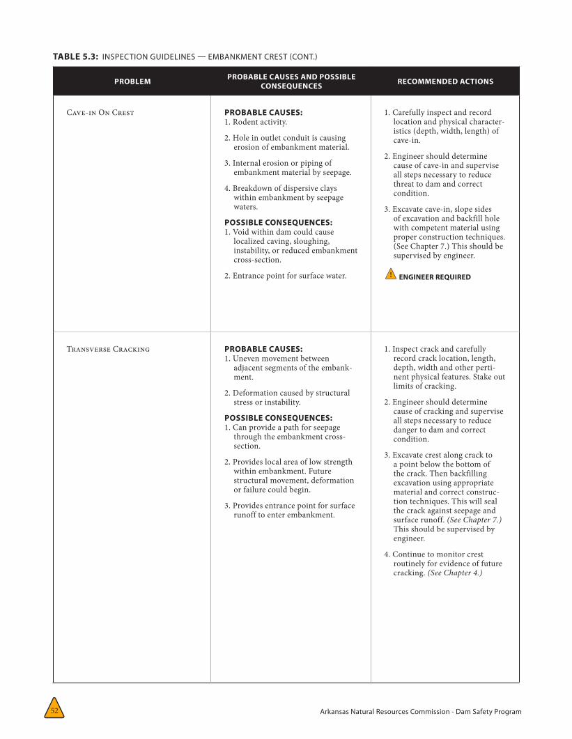
Arkansas Natural Resources Commission - Dam Safety Program52
TABLE 5.3: INSPECTION GUIDELINES — EMBANKMENT CREST (CONT.)
PROBLEM PROBABLE CAUSES AND POSSIBLE CONSEQUENCES RECOMMENDED ACTIONS
Cave-in On Crest PROBABLE CAUSES: 1. Rodent activity.
2. Hole in outlet conduit is causing erosion of embankment material.
3. Internal erosion or piping of embankment material by seepage.
4. Breakdown of dispersive clays within embankment by seepage waters.
POSSIBLE CONSEQUENCES: 1. Void within dam could cause
localized caving, sloughing, instability, or reduced embankment cross-section.
2. Entrance point for surface water.
1. Carefully inspect and record location and physical character-istics (depth, width, length) of cave-in.
2. Engineer should determine cause of cave-in and supervise all steps necessary to reduce threat to dam and correct condition.
3. Excavate cave-in, slope sides of excavation and backfill hole with competent material using proper construction techniques. (See Chapter 7.) This should be supervised by engineer.
! ENGINEER REQUIRED
Transverse Cracking PROBABLE CAUSES: 1. Uneven movement between
adjacent segments of the embank-ment.
2. Deformation caused by structural stress or instability.
POSSIBLE CONSEQUENCES: 1. Can provide a path for seepage
through the embankment cross-section.
2. Provides local area of low strength within embankment. Future structural movement, deformation or failure could begin.
3. Provides entrance point for surface runoff to enter embankment.
1. Inspect crack and carefully record crack location, length, depth, width and other perti-nent physical features. Stake out limits of cracking.
2. Engineer should determine cause of cracking and supervise all steps necessary to reduce danger to dam and correct condition.
3. Excavate crest along crack to a point below the bottom of the crack. Then backfilling excavation using appropriate material and correct construc-tion techniques. This will seal the crack against seepage and surface runoff. (See Chapter 7.) This should be supervised by engineer.
4. Continue to monitor crest routinely for evidence of future cracking. (See Chapter 4.)
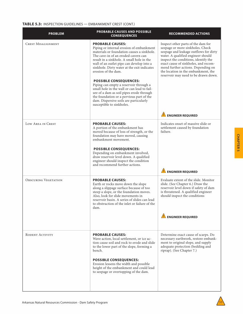
Arkansas Natural Resources Commission - Dam Safety Program 53
CH
APTER 5
PROBLEM PROBABLE CAUSES AND POSSIBLE CONSEQUENCES RECOMMENDED ACTIONS
Crest Misalignment PROBABLE CAUSES: Piping or internal erosion of embankment materials or foundation causes a sinkhole. The cave-in of an eroded cavern can result in a sinkhole. A small hole in the wall of an outlet pipe can develop into a sinkhole. Dirty water at the exit indicates erosion of the dam.
POSSIBLE CONSEQUENCES: Piping can empty a reservoir through a small hole in the wall or can lead to fail-ure of a dam as soil pipes erode through the foundation or a pervious part of the dam. Dispersive soils are particularly susceptible to sinkholes.
Inspect other parts of the dam for seepage or more sinkholes. Check seepage and leakage outflows for dirty water. A qualified engineer should inspect the conditions, identify the exact cause of sinkholes, and recom-mend further actions. Depending on the location in the embankment, the reservoir may need to be drawn down.
! ENGINEER REQUIRED
Low Area in Crest PROBABLE CAUSES: A portion of the embankment has moved because of loss of strength, or the foundation may have moved, causing embankment movement.
POSSIBLE CONSEQUENCES: Depending on embankment involved, draw reservoir level down. A qualified engineer should inspect the condition and recommend further actions.
Indicates onset of massive slide or settlement caused by foundation failure.
! ENGINEER REQUIRED
Obscuring Vegetation PROBABLE CAUSES: Earth or rocks move down the slope along a slippage surface because of too steep a slope, or the foundation moves. Also, look for slide movements in reservoir basin. A series of slides can lead to obstruction of the inlet or failure of the dam.
Evaluate extent of the slide. Monitor slide. (See Chapter 6.) Draw the reservoir level down if safety of dam is threatened. A qualified engineer should inspect the conditions
! ENGINEER REQUIRED
Rodent Activity PROBABLE CAUSES: Wave action, local settlement, or ice ac-tion cause soil and rock to erode and slide to the lower part of the slope, forming a bench.
POSSIBLE CONSEQUENCES: Erosion lessens the width and possible height of the embankment and could lead to seepage or overtopping of the dam.
Determine exact cause of scarps. Do necessary earthwork, restore embank-ment to original slope, and supply adequate protection (bedding and riprap). (See Chapter 7.)
TABLE 5.3: INSPECTION GUIDELINES — EMBANKMENT CREST (CONT.)
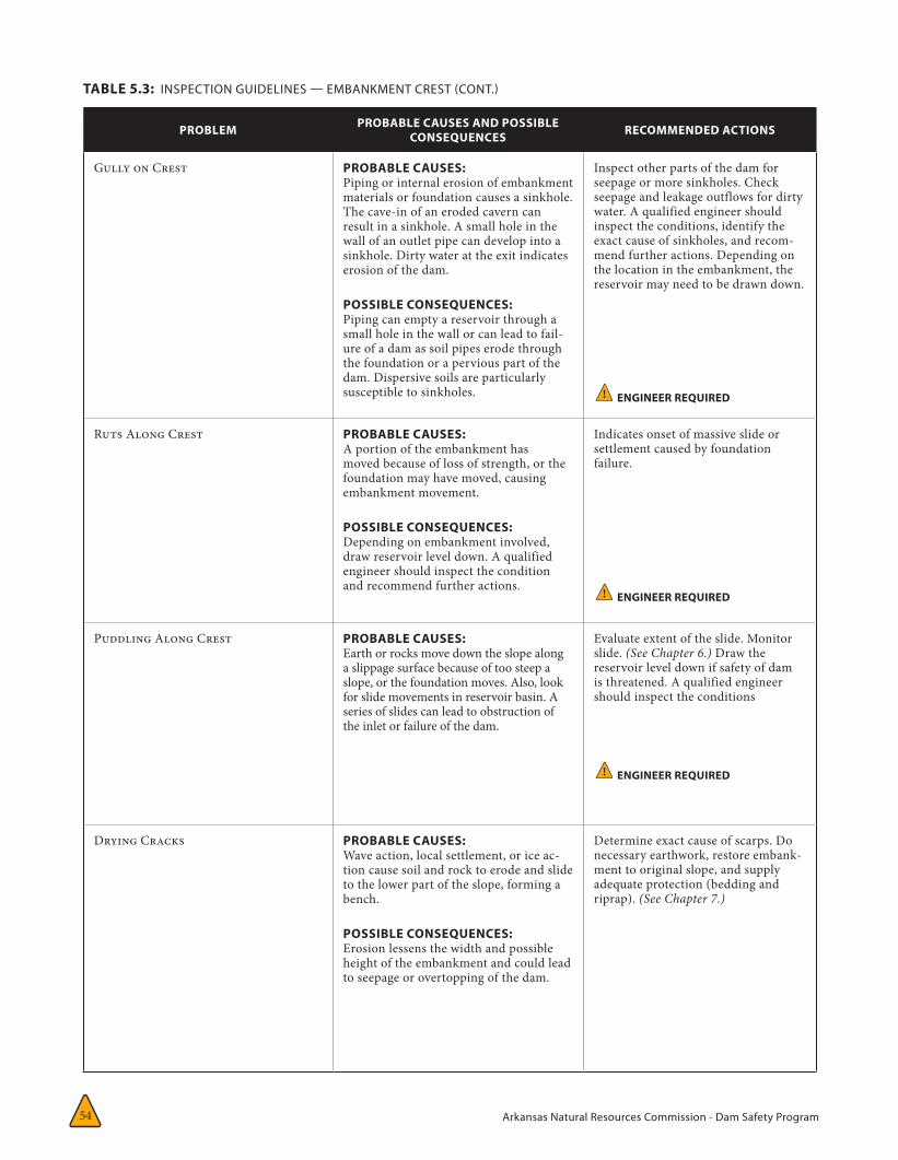
Arkansas Natural Resources Commission - Dam Safety Program54
PROBLEM PROBABLE CAUSES AND POSSIBLE CONSEQUENCES RECOMMENDED ACTIONS
Gully on Crest PROBABLE CAUSES: Piping or internal erosion of embankment materials or foundation causes a sinkhole. The cave-in of an eroded cavern can result in a sinkhole. A small hole in the wall of an outlet pipe can develop into a sinkhole. Dirty water at the exit indicates erosion of the dam.
POSSIBLE CONSEQUENCES: Piping can empty a reservoir through a small hole in the wall or can lead to fail-ure of a dam as soil pipes erode through the foundation or a pervious part of the dam. Dispersive soils are particularly susceptible to sinkholes.
Inspect other parts of the dam for seepage or more sinkholes. Check seepage and leakage outflows for dirty water. A qualified engineer should inspect the conditions, identify the exact cause of sinkholes, and recom-mend further actions. Depending on the location in the embankment, the reservoir may need to be drawn down.
! ENGINEER REQUIRED
Ruts Along Crest PROBABLE CAUSES: A portion of the embankment has moved because of loss of strength, or the foundation may have moved, causing embankment movement.
POSSIBLE CONSEQUENCES: Depending on embankment involved, draw reservoir level down. A qualified engineer should inspect the condition and recommend further actions.
Indicates onset of massive slide or settlement caused by foundation failure.
! ENGINEER REQUIRED
Puddling Along Crest PROBABLE CAUSES: Earth or rocks move down the slope along a slippage surface because of too steep a slope, or the foundation moves. Also, look for slide movements in reservoir basin. A series of slides can lead to obstruction of the inlet or failure of the dam.
Evaluate extent of the slide. Monitor slide. (See Chapter 6.) Draw the reservoir level down if safety of dam is threatened. A qualified engineer should inspect the conditions
! ENGINEER REQUIRED
Drying Cracks PROBABLE CAUSES: Wave action, local settlement, or ice ac-tion cause soil and rock to erode and slide to the lower part of the slope, forming a bench.
POSSIBLE CONSEQUENCES: Erosion lessens the width and possible height of the embankment and could lead to seepage or overtopping of the dam.
Determine exact cause of scarps. Do necessary earthwork, restore embank-ment to original slope, and supply adequate protection (bedding and riprap). (See Chapter 7.)
TABLE 5.3: INSPECTION GUIDELINES — EMBANKMENT CREST (CONT.)
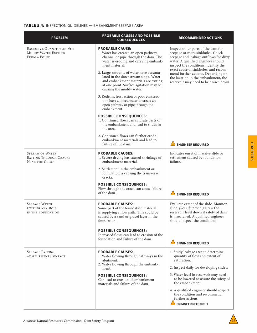
Arkansas Natural Resources Commission - Dam Safety Program 55
CH
APTER 5
PROBLEM PROBABLE CAUSES AND POSSIBLE CONSEQUENCES RECOMMENDED ACTIONS
Excessive Quantity and/orMuddy Water ExitingFrom a Point
PROBABLE CAUSE:1. Water has created an open pathway,
channel or pipe through the dam. The water is eroding and carrying embank-ment material.
2. Large amounts of water have accumu-lated in the downstream slope. Water and embankment materials are exiting at one point. Surface agitation may be causing the muddy water.
3. Rodents, frost action or poor construc-tion have allowed water to create an open pathway or pipe through the embankment.
POSSIBLE CONSEQUENCES:1. Continued flows can saturate parts of
the embankment and lead to slides in the area.
2. Continued flows can further erode embankment materials and lead to failure of the dam.
Inspect other parts of the dam for seepage or more sinkholes. Check seepage and leakage outflows for dirty water. A qualified engineer should inspect the conditions, identify the exact cause of sinkholes, and recom-mend further actions. Depending on the location in the embankment, the reservoir may need to be drawn down.
! ENGINEER REQUIRED
Stream of WaterExiting Through CracksNear the Crest
PROBABLE CAUSES: 1. Severe drying has caused shrinkage of
embankment material.
2. Settlement in the embankment or foundation is causing the transverse cracks.
POSSIBLE CONSEQUENCES:Flow through the crack can cause failure of the dam.
Indicates onset of massive slide or settlement caused by foundation failure.
! ENGINEER REQUIRED
Seepage WaterExiting as a Boilin the Foundation
PROBABLE CAUSES: Some part of the foundation material is supplying a flow path. This could be caused by a sand or gravel layer in the foundation.
POSSIBLE CONSEQUENCES:Increased flows can lead to erosion of the foundation and failure of the dam.
Evaluate extent of the slide. Monitor slide. (See Chapter 6.) Draw the reservoir level down if safety of dam is threatened. A qualified engineer should inspect the conditions
! ENGINEER REQUIRED
Seepage Exitingat Abutment Contact
PROBABLE CAUSES: 1. Water flowing through pathways in the
abutment.2. Water flowing through the embank-
ment.
POSSIBLE CONSEQUENCES:Can lead to erosion of embankment materials and failure of the dam.
1. Study leakage area to determine quantity of flow and extent of saturation.
2. Inspect daily for developing slides.
3. Water level in reservoir may need to be lowered to assure the safety of the embankment.
4. A qualified engineer should inspect the condition and recommend further actions.
! ENGINEER REQUIRED
TABLE 5.4: INSPECTION GUIDELINES — EMBANKMENT SEEPAGE AREA
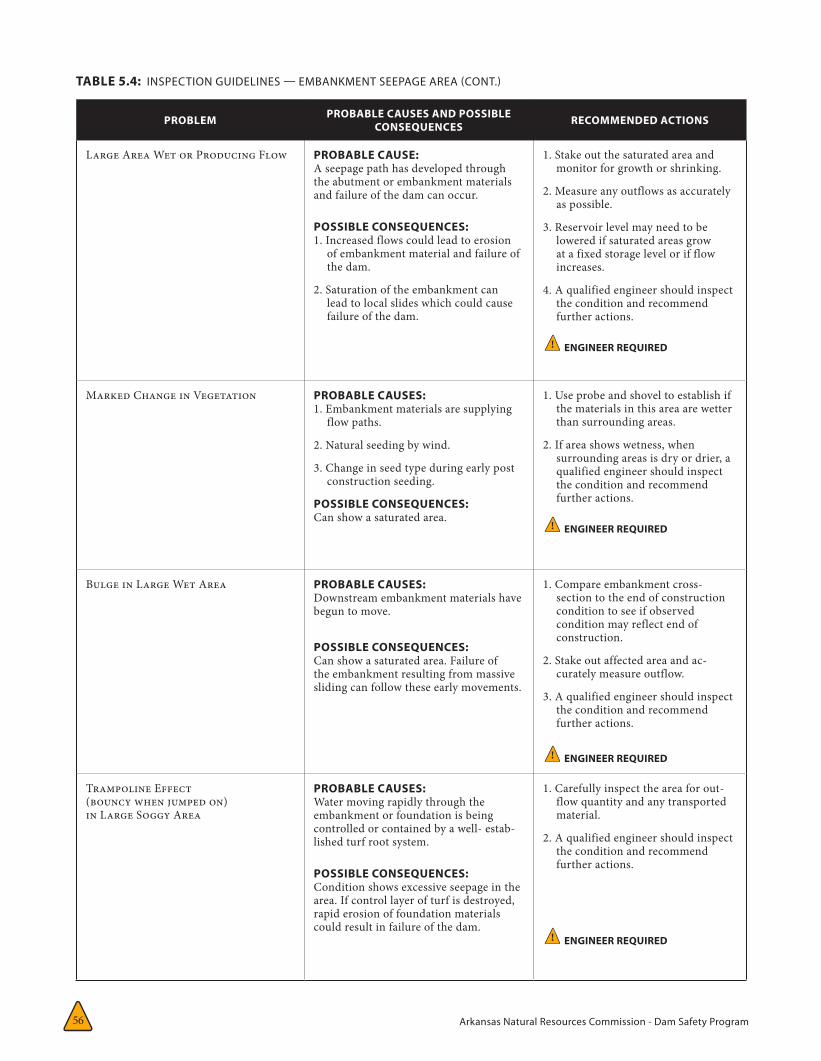
Arkansas Natural Resources Commission - Dam Safety Program56
PROBLEM PROBABLE CAUSES AND POSSIBLE CONSEQUENCES RECOMMENDED ACTIONS
Large Area Wet or Producing Flow PROBABLE CAUSE:A seepage path has developed through the abutment or embankment materials and failure of the dam can occur.
POSSIBLE CONSEQUENCES:1. Increased flows could lead to erosion
of embankment material and failure of the dam.
2. Saturation of the embankment can lead to local slides which could cause failure of the dam.
1. Stake out the saturated area and monitor for growth or shrinking.
2. Measure any outflows as accurately as possible.
3. Reservoir level may need to be lowered if saturated areas grow at a fixed storage level or if flow increases.
4. A qualified engineer should inspect the condition and recommend further actions.
! ENGINEER REQUIRED
Marked Change in Vegetation PROBABLE CAUSES: 1. Embankment materials are supplying
flow paths.
2. Natural seeding by wind.
3. Change in seed type during early post construction seeding.
POSSIBLE CONSEQUENCES:Can show a saturated area.
1. Use probe and shovel to establish if the materials in this area are wetter than surrounding areas.
2. If area shows wetness, when surrounding areas is dry or drier, a qualified engineer should inspect the condition and recommend further actions.
! ENGINEER REQUIRED
Bulge in Large Wet Area PROBABLE CAUSES: Downstream embankment materials have begun to move.
POSSIBLE CONSEQUENCES:Can show a saturated area. Failure of the embankment resulting from massive sliding can follow these early movements.
1. Compare embankment cross-section to the end of construction condition to see if observed condition may reflect end of construction.
2. Stake out affected area and ac-curately measure outflow.
3. A qualified engineer should inspect the condition and recommend further actions.
! ENGINEER REQUIRED
Trampoline Effect(bouncy when jumped on)in Large Soggy Area
PROBABLE CAUSES: Water moving rapidly through the embankment or foundation is being controlled or contained by a well- estab-lished turf root system.
POSSIBLE CONSEQUENCES:Condition shows excessive seepage in the area. If control layer of turf is destroyed, rapid erosion of foundation materials could result in failure of the dam.
1. Carefully inspect the area for out-flow quantity and any transported material.
2. A qualified engineer should inspect the condition and recommend further actions.
! ENGINEER REQUIRED
TABLE 5.4: INSPECTION GUIDELINES — EMBANKMENT SEEPAGE AREA (CONT.)
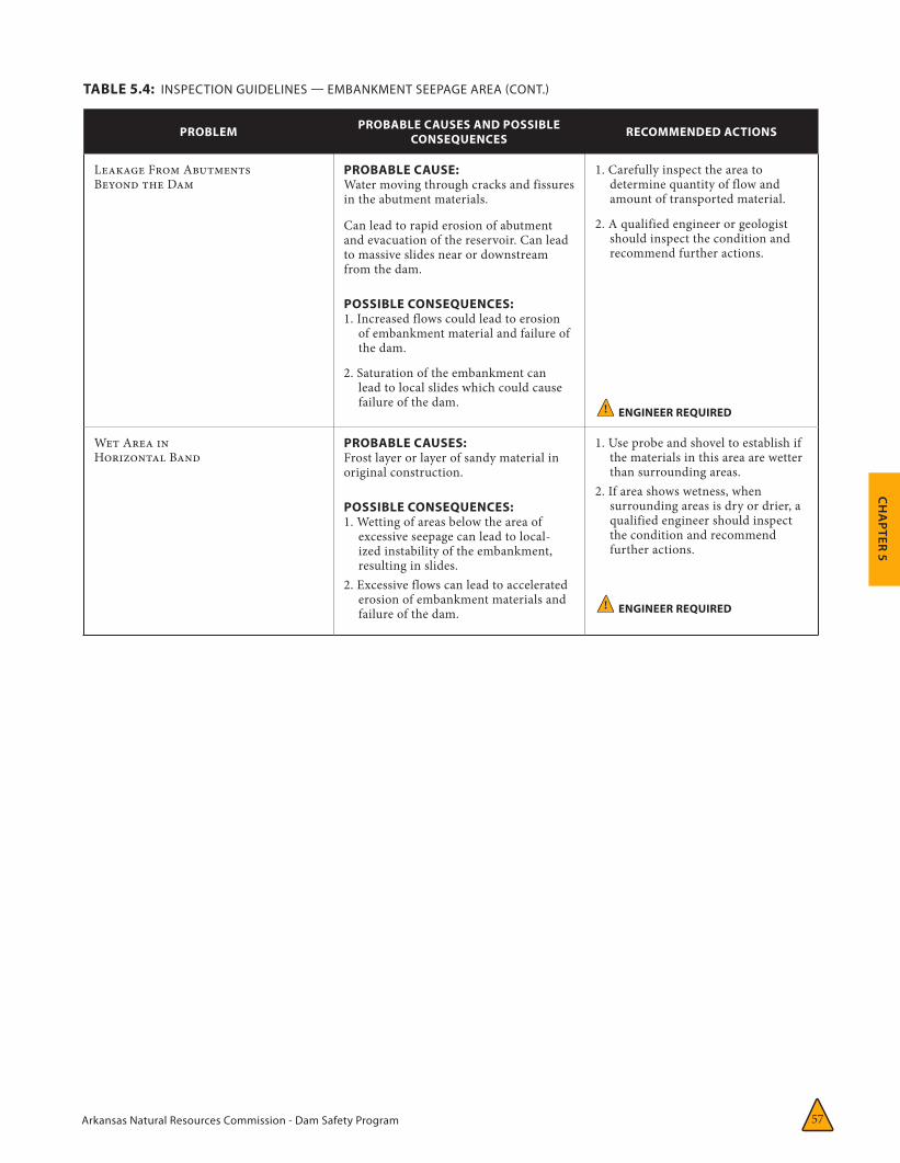
Arkansas Natural Resources Commission - Dam Safety Program 57
CH
APTER 5
PROBLEM PROBABLE CAUSES AND POSSIBLE CONSEQUENCES RECOMMENDED ACTIONS
Leakage From AbutmentsBeyond the Dam
PROBABLE CAUSE:Water moving through cracks and fissures in the abutment materials.
Can lead to rapid erosion of abutment and evacuation of the reservoir. Can lead to massive slides near or downstream from the dam.
POSSIBLE CONSEQUENCES:1. Increased flows could lead to erosion
of embankment material and failure of the dam.
2. Saturation of the embankment can lead to local slides which could cause failure of the dam.
1. Carefully inspect the area to determine quantity of flow and amount of transported material.
2. A qualified engineer or geologist should inspect the condition and recommend further actions.
! ENGINEER REQUIRED
Wet Area inHorizontal Band
PROBABLE CAUSES: Frost layer or layer of sandy material in original construction.
POSSIBLE CONSEQUENCES:1. Wetting of areas below the area of
excessive seepage can lead to local-ized instability of the embankment, resulting in slides.
2. Excessive flows can lead to accelerated erosion of embankment materials and failure of the dam.
1. Use probe and shovel to establish if the materials in this area are wetter than surrounding areas.
2. If area shows wetness, when surrounding areas is dry or drier, a qualified engineer should inspect the condition and recommend further actions.
! ENGINEER REQUIRED
TABLE 5.4: INSPECTION GUIDELINES — EMBANKMENT SEEPAGE AREA (CONT.)
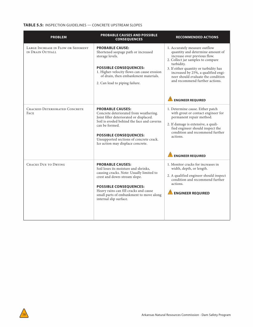
Arkansas Natural Resources Commission - Dam Safety Program58
PROBLEM PROBABLE CAUSES AND POSSIBLE CONSEQUENCES RECOMMENDED ACTIONS
Large Increase in Flow or Sediment in Drain Outfall
PROBABLE CAUSE:Shortened seepage path or increased storage levels.
POSSIBLE CONSEQUENCES:1. Higher-velocity flows can cause erosion
of drain, then embankment materials.
2. Can lead to piping failure.
1. Accurately measure outflow quantity and determine amount of increase over previous flow.
2. Collect jar samples to compare turbidity.
3. If either quantity or turbidity has increased by 25%, a qualified engi-neer should evaluate the condition and recommend further actions.
! ENGINEER REQUIRED
Cracked Deteriorated Concrete Face
PROBABLE CAUSES: Concrete deteriorated from weathering.Joint filler deteriorated or displaced.Soil is eroded behind the face and caverns can be formed.
POSSIBLE CONSEQUENCES:Unsupported sections of concrete crack. Ice action may displace concrete.
1. Determine cause. Either patch with grout or contact engineer for permanent repair method.
2. If damage is extensive, a quali-fied engineer should inspect the condition and recommend further actions.
! ENGINEER REQUIRED
Cracks Due to Drying PROBABLE CAUSES: Soil loses its moisture and shrinks, causing cracks. Note: Usually limited to crest and down-stream slope.
POSSIBLE CONSEQUENCES:Heavy rains can fill cracks and cause small parts of embankment to move along internal slip surface.
1. Monitor cracks for increases in width, depth, or length.
2. A qualified engineer should inspect condition and recommend further actions.
! ENGINEER REQUIRED
TABLE 5.5: INSPECTION GUIDELINES — CONCRETE UPSTREAM SLOPES
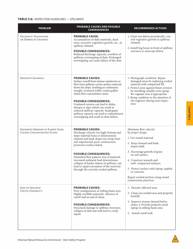
Arkansas Natural Resources Commission - Dam Safety Program 59
CH
APTER 5
PROBLEM PROBABLE CAUSES AND POSSIBLE CONSEQUENCES RECOMMENDED ACTIONS
Excessive Vegetation or Debris in Channel
PROBABLE CAUSE:Accumulation of slide materials, dead trees, excessive vegetative growth, etc., in spillway channel.
POSSIBLE CONSEQUENCES:Reduced discharge capacity; overflow of spillway, overtopping of dam. Prolonged overtopping can cause failure of the dam
1. Clean out debris periodically; con-trol vegetative growth in spillway channel.
2. Install log boom in front of spillway entrance to intercept debris.
Erosion Channels PROBABLE CAUSES: Surface runoff from intense rainstorms or flow from spillway carries surface material down the slope, resulting in continuous troughs. Livestock traffic creates gullies where flow concentrates varies.
POSSIBLE CONSEQUENCES:Unabated erosion can lead to slides, slumps or slips which can result in reduced spillway capacity. Inadequate spillway capacity can lead to embankment overtopping and result in dam failure.
1. Photograph condition. Repair damaged areas by replacing eroded material with compacted fill.
2. Protect areas against future erosion by installing suitable rock riprap. Re-vegetate area if appropriate.
3. Bring condition to the attention of the engineer during next inspec-tion.
Excessive Erosion in Earth-Slide Causes Concentrated Flows
PROBABLE CAUSES: Discharge velocity too high; bottom and slope material loose or deteriorated; channel and bank slopes too steep; bare soil unprotected; poor construction protective surface failed.
POSSIBLE CONSEQUENCES:Disturbed flow pattern; loss of material, increased sediment load downstream, collapse of banks; failure of spillway; can lead to rapid evacuation of the reservoir through the severely eroded spillway.
Minimize flow velocity by proper design.
1. Use sound material.
2. Keep channel and bank slopes mild.
3. Encourage growth of grass on soil surface.
4. Construct smooth and well- compacted surfaces.
5. Protect surface with riprap, asphalt or concrete.
Repair eroded portion using sound construction practices.
End of SpillwayChute Undercut
PROBABLE CAUSES: Poor configuration of stilling basin area. Highly erodible materials. Absence of cutoff wall at end of chute.
POSSIBLE CONSEQUENCES:Structural damage to spillway structure; collapse of slab and wall lead to costly repair.
1. Dewater affected area;
2. Clean out eroded area and properly backfill.
3. Improve stream channel below chute; 4. Provide properly sized riprap in stilling basin area.
5. Install cutoff wall.
TABLE 5.6: INSPECTION GUIDELINES — SPILLWAYS
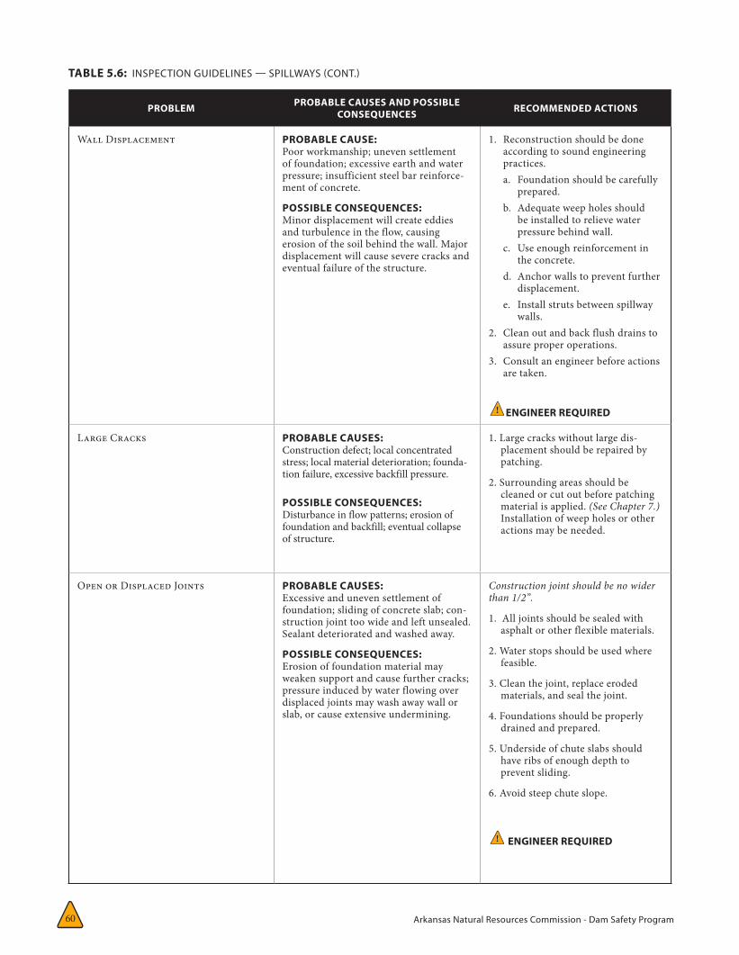
Arkansas Natural Resources Commission - Dam Safety Program60
PROBLEM PROBABLE CAUSES AND POSSIBLE CONSEQUENCES RECOMMENDED ACTIONS
Wall Displacement PROBABLE CAUSE:Poor workmanship; uneven settlement of foundation; excessive earth and water pressure; insufficient steel bar reinforce-ment of concrete.
POSSIBLE CONSEQUENCES:Minor displacement will create eddies and turbulence in the flow, causing erosion of the soil behind the wall. Major displacement will cause severe cracks and eventual failure of the structure.
1. Reconstruction should be done according to sound engineering practices. a. Foundation should be carefully
prepared. b. Adequate weep holes should
be installed to relieve water pressure behind wall.
c. Use enough reinforcement in the concrete.
d. Anchor walls to prevent further displacement.
e. Install struts between spillway walls.
2. Clean out and back flush drains to assure proper operations.
3. Consult an engineer before actions are taken.
! ENGINEER REQUIRED
Large Cracks PROBABLE CAUSES: Construction defect; local concentrated stress; local material deterioration; founda-tion failure, excessive backfill pressure.
POSSIBLE CONSEQUENCES:Disturbance in flow patterns; erosion of foundation and backfill; eventual collapse of structure.
1. Large cracks without large dis-placement should be repaired by patching.
2. Surrounding areas should be cleaned or cut out before patching material is applied. (See Chapter 7.) Installation of weep holes or other actions may be needed.
Open or Displaced Joints PROBABLE CAUSES: Excessive and uneven settlement of foundation; sliding of concrete slab; con-struction joint too wide and left unsealed. Sealant deteriorated and washed away.
POSSIBLE CONSEQUENCES:Erosion of foundation material may weaken support and cause further cracks; pressure induced by water flowing over displaced joints may wash away wall or slab, or cause extensive undermining.
Construction joint should be no wider than 1/2”.
1. All joints should be sealed with asphalt or other flexible materials.
2. Water stops should be used where feasible.
3. Clean the joint, replace eroded materials, and seal the joint.
4. Foundations should be properly drained and prepared.
5. Underside of chute slabs should have ribs of enough depth to prevent sliding.
6. Avoid steep chute slope.
! ENGINEER REQUIRED
TABLE 5.6: INSPECTION GUIDELINES — SPILLWAYS (CONT.)
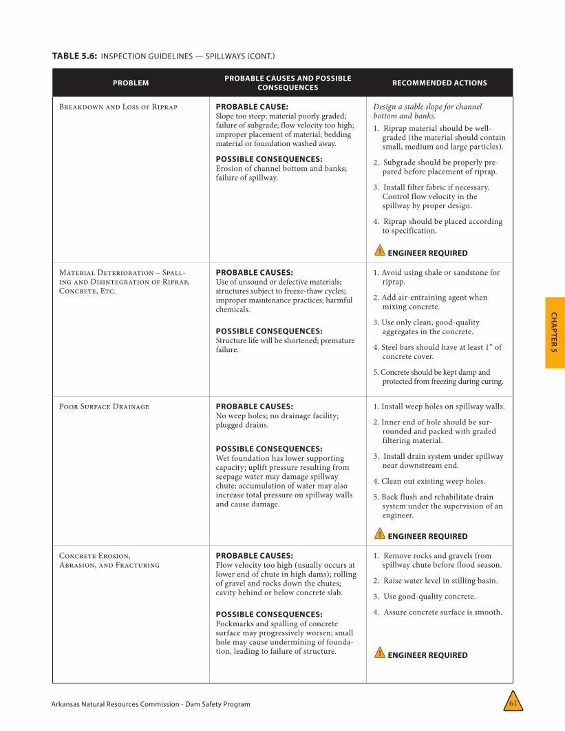
Arkansas Natural Resources Commission - Dam Safety Program 61
CH
APTER 5
PROBLEM PROBABLE CAUSES AND POSSIBLE CONSEQUENCES RECOMMENDED ACTIONS
Breakdown and Loss of Riprap PROBABLE CAUSE:Slope too steep; material poorly graded; failure of subgrade; flow velocity too high; improper placement of material; bedding material or foundation washed away.
POSSIBLE CONSEQUENCES:Erosion of channel bottom and banks; failure of spillway.
Design a stable slope for channel bottom and banks. 1. Riprap material should be well-
graded (the material should contain small, medium and large particles).
2. Subgrade should be properly pre-pared before placement of riprap.
3. Install filter fabric if necessary. Control flow velocity in the spillway by proper design.
4. Riprap should be placed according to specification.
! ENGINEER REQUIRED
Material Deterioration – Spall-ing and Disintegration of Riprap, Concrete, Etc.
PROBABLE CAUSES: Use of unsound or defective materials; structures subject to freeze-thaw cycles; improper maintenance practices; harmful chemicals.
POSSIBLE CONSEQUENCES:Structure life will be shortened; premature failure.
1. Avoid using shale or sandstone for riprap.
2. Add air-entraining agent when mixing concrete.
3. Use only clean, good-quality aggregates in the concrete.
4. Steel bars should have at least 1” of concrete cover.
5. Concrete should be kept damp and protected from freezing during curing.
Poor Surface Drainage PROBABLE CAUSES: No weep holes; no drainage facility; plugged drains.
POSSIBLE CONSEQUENCES:Wet foundation has lower supporting capacity; uplift pressure resulting from seepage water may damage spillway chute; accumulation of water may also increase total pressure on spillway walls and cause damage.
1. Install weep holes on spillway walls.
2. Inner end of hole should be sur-rounded and packed with graded filtering material.
3. Install drain system under spillway near downstream end.
4. Clean out existing weep holes.
5. Back flush and rehabilitate drain system under the supervision of an engineer.
! ENGINEER REQUIRED
Concrete Erosion, Abrasion, and Fracturing
PROBABLE CAUSES: Flow velocity too high (usually occurs at lower end of chute in high dams); rolling of gravel and rocks down the chutes; cavity behind or below concrete slab.
POSSIBLE CONSEQUENCES:Pockmarks and spalling of concrete surface may progressively worsen; small hole may cause undermining of founda-tion, leading to failure of structure.
1. Remove rocks and gravels from spillway chute before flood season.
2. Raise water level in stilling basin.
3. Use good-quality concrete.
4. Assure concrete surface is smooth.
! ENGINEER REQUIRED
TABLE 5.6: INSPECTION GUIDELINES — SPILLWAYS (CONT.)
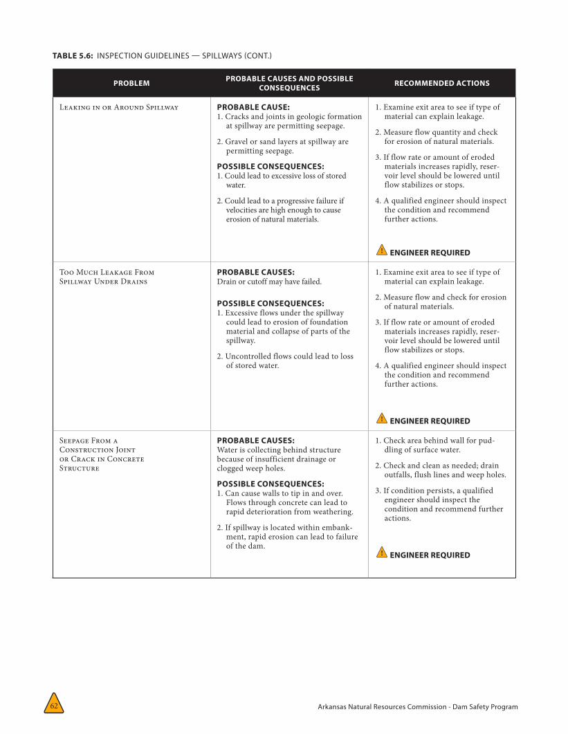
Arkansas Natural Resources Commission - Dam Safety Program62
PROBLEM PROBABLE CAUSES AND POSSIBLE CONSEQUENCES RECOMMENDED ACTIONS
Leaking in or Around Spillway PROBABLE CAUSE:1. Cracks and joints in geologic formation
at spillway are permitting seepage.
2. Gravel or sand layers at spillway are permitting seepage.
POSSIBLE CONSEQUENCES:1. Could lead to excessive loss of stored
water.
2. Could lead to a progressive failure if velocities are high enough to cause erosion of natural materials.
1. Examine exit area to see if type of material can explain leakage.
2. Measure flow quantity and check for erosion of natural materials.
3. If flow rate or amount of eroded materials increases rapidly, reser-voir level should be lowered until flow stabilizes or stops.
4. A qualified engineer should inspect the condition and recommend further actions.
! ENGINEER REQUIRED
Too Much Leakage FromSpillway Under Drains
PROBABLE CAUSES: Drain or cutoff may have failed.
POSSIBLE CONSEQUENCES:1. Excessive flows under the spillway
could lead to erosion of foundation material and collapse of parts of the spillway.
2. Uncontrolled flows could lead to loss of stored water.
1. Examine exit area to see if type of material can explain leakage.
2. Measure flow and check for erosion of natural materials.
3. If flow rate or amount of eroded materials increases rapidly, reser-voir level should be lowered until flow stabilizes or stops.
4. A qualified engineer should inspect the condition and recommend further actions.
! ENGINEER REQUIRED
Seepage From aConstruction Jointor Crack in ConcreteStructure
PROBABLE CAUSES: Water is collecting behind structure because of insufficient drainage or clogged weep holes.
POSSIBLE CONSEQUENCES:1. Can cause walls to tip in and over.
Flows through concrete can lead to rapid deterioration from weathering.
2. If spillway is located within embank-ment, rapid erosion can lead to failure of the dam.
1. Check area behind wall for pud-dling of surface water.
2. Check and clean as needed; drain outfalls, flush lines and weep holes.
3. If condition persists, a qualified engineer should inspect the condition and recommend further actions.
! ENGINEER REQUIRED
TABLE 5.6: INSPECTION GUIDELINES — SPILLWAYS (CONT.)
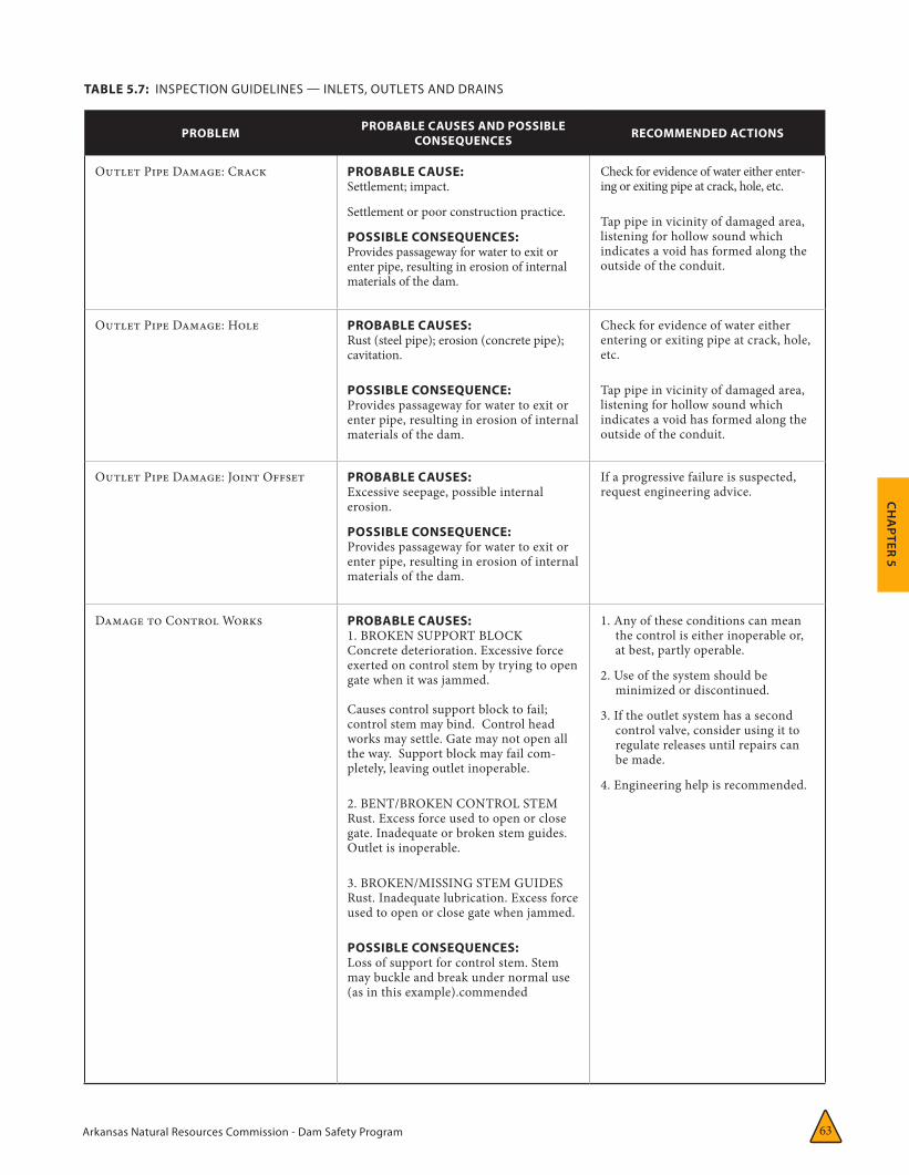
Arkansas Natural Resources Commission - Dam Safety Program 63
CH
APTER 5
PROBLEM PROBABLE CAUSES AND POSSIBLE CONSEQUENCES RECOMMENDED ACTIONS
Outlet Pipe Damage: Crack PROBABLE CAUSE:Settlement; impact.
Settlement or poor construction practice.
POSSIBLE CONSEQUENCES:Provides passageway for water to exit or enter pipe, resulting in erosion of internal materials of the dam.
Check for evidence of water either enter-ing or exiting pipe at crack, hole, etc.
Tap pipe in vicinity of damaged area, listening for hollow sound which indicates a void has formed along the outside of the conduit.
Outlet Pipe Damage: Hole PROBABLE CAUSES: Rust (steel pipe); erosion (concrete pipe); cavitation.
POSSIBLE CONSEQUENCE:Provides passageway for water to exit or enter pipe, resulting in erosion of internal materials of the dam.
Check for evidence of water either entering or exiting pipe at crack, hole, etc.
Tap pipe in vicinity of damaged area, listening for hollow sound which indicates a void has formed along the outside of the conduit.
Outlet Pipe Damage: Joint Offset PROBABLE CAUSES: Excessive seepage, possible internal erosion.
POSSIBLE CONSEQUENCE:Provides passageway for water to exit or enter pipe, resulting in erosion of internal materials of the dam.
If a progressive failure is suspected, request engineering advice.
Damage to Control Works PROBABLE CAUSES: 1. BROKEN SUPPORT BLOCKConcrete deterioration. Excessive force exerted on control stem by trying to open gate when it was jammed.
Causes control support block to fail; control stem may bind. Control head works may settle. Gate may not open all the way. Support block may fail com-pletely, leaving outlet inoperable.
2. BENT/BROKEN CONTROL STEMRust. Excess force used to open or close gate. Inadequate or broken stem guides. Outlet is inoperable.
3. BROKEN/MISSING STEM GUIDESRust. Inadequate lubrication. Excess force used to open or close gate when jammed.
POSSIBLE CONSEQUENCES:Loss of support for control stem. Stem may buckle and break under normal use (as in this example).commended
1. Any of these conditions can mean the control is either inoperable or, at best, partly operable.
2. Use of the system should be minimized or discontinued.
3. If the outlet system has a second control valve, consider using it to regulate releases until repairs can be made.
4. Engineering help is recommended.
TABLE 5.7: INSPECTION GUIDELINES — INLETS, OUTLETS AND DRAINS

Arkansas Natural Resources Commission - Dam Safety Program64
PROBLEM PROBABLE CAUSES AND POSSIBLE CONSEQUENCES RECOMMENDED ACTIONS
Failure of Concrete Outfall Structure
PROBABLE CAUSE:Excessive side pressures on non-reinforced concrete structure. Poor concrete quality.
POSSIBLE CONSEQUENCES:Loss of outfall structure exposes embank-ment to erosion by outlet releases.
1. Check for progressive failure by monitoring typical dimension.
2. Repair by patching cracks and supplying drainage around concrete structure. Outfall structure may need total replacement.
Outlet Releases Eroding Toe of Dam
PROBABLE CAUSES: Outlet pipe too short. Lack of energy-dis-sipating pool or structure at downstream end of conduit.
POSSIBLE CONSEQUENCES:Erosion of toe over steepens downstream slope, causing progressive sloughing.
1. Extend pipe beyond toe (use pipe of same size and material, and form watertight connection to existing conduit).
2. Protect embankment with riprap over suitable bedding.
Valve Leakage: Debris Stuck Under Gate
PROBABLE CAUSES: Trash rack missing or damaged.Gate will not close.
POSSIBLE CONSEQUENCES:Gate or stem may be damaged in effort to close gate.
Raise and lower gate slowly until debris is loosened and floats past valve. When reservoir is lowered, repair or replace trash rack.
Valve Leakage: Cracked Gate Leaf
PROBABLE CAUSES: Ice action, rust, affect vibration, or stress resulting from forcing gate closed when it is jammed.
POSSIBLE CONSEQUENCES:Gate-leaf valve may fail completely, evacuating reservoir.
1. Use valve only in fully open or closed position.
2. Minimize use of valve until leaf can be repaired or replaced.
Valve Leakage: Damaged Gate Seat or Guides
PROBABLE CAUSES: Rust, erosion, cavitation, vibration or wear.
POSSIBLE CONSEQUENCES:Leakage and loss of support for gate leaf.Gate may bind in guides and become inoperable.
1. Minimize use of valve until guides or seats can be repaired.
2. If cavitation is the cause, check to see if air-vent pipe exists, and is unobstructed.
Seepage Water Exiting From a Point Adjacent to the Outlet
PROBABLE CAUSE: 1. A break in the outlet pipe.
2. A path for flow has developed along the outside of the outlet pipe.
POSSIBLE CONSEQUENCES:Continued flows can lead to erosion of the embankment materials and failure of the dam.
1. Thoroughly investigate the area by probing and/or shoveling to try to determine cause.
2. Determine if leakage water is carrying soil particles.
3. Determine quantity of flow.
4. If flow increases or is carrying embankment materials, reservoir level should be lowered until leakage stops.
5. A qualified engineer should inspect the condition and recommend further actions.
! ENGINEER REQUIRED
TABLE 5.7: INSPECTION GUIDELINES — INLETS, OUTLETS AND DRAINS (CONT.)
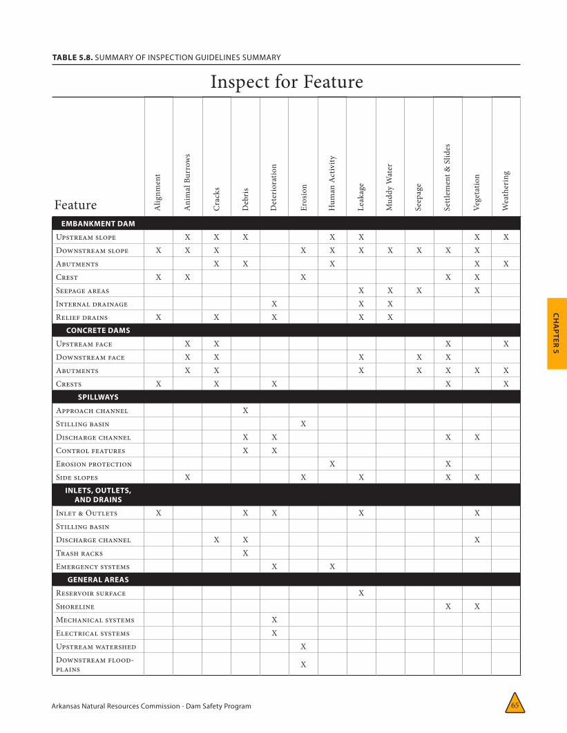
Arkansas Natural Resources Commission - Dam Safety Program 65
CH
APTER 5
Alig
nmen
t
Ani
mal
Bur
row
s
Cra
cks
Deb
ris
Det
erio
ratio
n
Eros
ion
Hum
an A
ctiv
ity
Leak
age
Mud
dy W
ater
Seep
age
Settl
emen
t & S
lides
Vege
tatio
n
Wea
ther
ing
TABLE 5.8. SUMMARY OF INSPECTION GUIDELINES SUMMARY
Inspect for Feature
FeatureEMBANKMENT DAM
Upstream slope X X X X X X XDownstream slope X X X X X X X X X XAbutments X X X X XCrest X X X X XSeepage areas X X X XInternal drainage X X XRelief drains X X X X X
CONCRETE DAMS
Upstream face X X X XDownstream face X X X X XAbutments X X X X X X XCrests X X X X X
SPILLWAYS
Approach channel XStilling basin XDischarge channel X X X XControl features X XErosion protection X XSide slopes X X X X X
INLETS, OUTLETS, AND DRAINS
Inlet & Outlets X X X X XStilling basinDischarge channel X X XTrash racks XEmergency systems X X
GENERAL AREAS
Reservoir surface XShoreline X XMechanical systems XElectrical systems XUpstream watershed XDownstream flood-plains X
Arkansas Natural Resources Commission - Dam Safety Program 66
CH
APTER 6
General
The means and methods available to monitor phenomena that can lead to dam failure include a wide spectrum of
instruments and procedures, ranging from very simple to very complex. Any program of dam safety instrumentation must be properly de-signed and consistent with other project compo-nents, must be based on prevailing geotechnical conditions at the dam, and must consider the hydrologic and hydraulic factors present both before and after the project is in operation. Ev-ery instrument should have a specific purpose and expected design response.
Instruments designed for monitoring potential deficiencies at existing dams must take into account the threat to life and property that the dam presents. Thus, the extent and nature of the instrumentation depends not only on the complexity of the dam and the size of the reser-voir, but also on the potential for loss of life and property downstream.
An instrumentation program should involve instruments and evaluation methods that are as simple and straightforward as the project will allow. Beyond that, the dam owner should make a definite commitment to an ongoing monitor-ing program or the installation of instruments probably will be wasted.
This chapter discusses deficiencies in dams that may be discovered and the types of instruments
CHAPTER 6:
Instrumentation and Monitoring Guidelines 6
that may be used to monitor those deficiencies. Increased knowledge of these deficiencies ac-quired through a monitoring program is useful in determining both the cause of the deficiencies and the necessary remedies. Continued monitor-ing is important to determine that the remedy remains effective.
Involvement of qualified personnel in the de-sign, installation, monitoring, and evaluation of an instrumentation system is of prime impor-tance to the success of the program.
Reasons for InstrumentationInstrumentation and proper monitoring and evaluation are extremely valuable in determin-ing the performance of a dam.
SPECIFIC REASONS FORINSTRUMENTATION INCLUDE:
• WarningofaProblem:Ofteninstrumentscandetectunusualchanges,suchasfluctuationsinwaterpressurewithinthedamthatarenotvisible.Inothercases,gradualprogressivechangesinseepageflow,whichwouldgounnoticedvisually,canbemonitoredregularly.Thismonitoringcanwarnofthedevelopmentofaseriousseepageproblem.
• AnalyzingandDefiningaProblem:Instrumentationdataarefrequentlyusedto
Arkansas Natural Resources Commission - Dam Safety Program67
obtain engineering information necessary for analyzing and defining the extent of a problem. For example, downstream movement of a dam because of high reservoir-water pressure must be analyzed to determine if the movement is uniformly distributed along the dam; whether the movement is in the dam, the foundation, or both; and whether the movement is constant, increasing, or decreasing. Such information can then be used to design corrective measures.
• Behavior Is as Expected: Instruments installed at a dam may infrequently (or even never) show any anomaly or problem. However, even that information is valuable because it shows that the dam is performing as designed, offering peace of mind to you, the owner. Also, although a problem may appear to be extant or imminent, instrument readings might show that the deficiency (for example, increased seepage) is normal (merely a result of higher than normal reservoir level) and was foreseen in the dam’s design.
• EvaluatingRemedialActionPerformance:Manydams, particularly older ones, are modified to allow for increased capacity or to correct a deficiency. Instrument readings before and after the change allows analysis and evaluation of the performance of the modification.
Instrument Types and UsageA wide variety of devices and procedures are used to monitor dams. The features of dams and dam sites most often monitored by instruments include:
•movements(horizontal,vertical,rotationaland lateral)
• porepressureandupliftpressures
• waterlevelandflow
• seepageflow
• waterquality
• temperature
• crackandjointsize
• seismicactivity
• weatherandprecipitation
• stressandstrain
A thorough treatment of instrument types and their usage is presented in Dunnicliff 1993. Both the U.S. Bureau of Reclamation and the U.S. Army Corps of Engineers publish guides specific to the instrumentation and monitoring of dams. The Association of State Dam Safety Officials www.damsafety.org and the U.S. Soci-ety of Dams www.USSDams.org offer technical conferences, reports, and papers related to in-strumentation and dam safety monitoring.
VISUAL OBSERVATIONS: As discussed in Chapter 5, observations by you, the dam owner, or your rep-resentative may be the most important and effective means of monitoring the performance of a dam. An inspector, upon each visit to the dam site, should inspect it visually—at a minimum, walking along the dam alignment and looking for any signs of distress or unusual conditions.
MOVEMENTS: Movements occur in every dam. They are caused by stresses induced by reservoir water pressure, unstable slopes (low shearing strength), low foundation shearing strength, settlement (compressibility of foundation and dam materials), thrust due to arching, expansion resulting from temperature change, and heave resulting from hydrostatic uplift pressures. They can be categorized by direction:
Horizontal or translational movement commonly occurs in an upstream-downstream direction in both embankment and concrete dams. It involves the movement of an entire dam mass relative to its abutments or foundation. In an embankment dam, instruments commonly used for monitoring such movement include:
• extensometers,includingmulti-pointextensometers
• inclinometers
• embankmentmeasuringpoints
Arkansas Natural Resources Commission - Dam Safety Program 68
CH
APTER 6
• shearstrips
• structuralmeasuringpoints
• time-domainreflectometry(TDR)
For a concrete dam or concrete spillway, instru-ments for monitoring horizontal movements may include:
• crackmeasuringdevices
• extensometers,includingmulti-pointextensometers
• inclinometers
• structuralmeasuringpoints
• tapegauges
• strainmeters
• plumblines
• foundation-deformationgauges
• tiltmeters
• 2Dor3Djoint-movementindicators
• electro-levelbeams
• GPSmonitoringsystem
Vertical movement is commonly a result of consolidation of embankment or foundation materials resulting in settlement of the dam. Another cause is heave (particularly at the toe of a dam) caused by hydrostatic uplift pressures.
In an embankment dam, vertical movements may be monitored by:
• settlementplatesandsensors
• extensometers
• embankmentsurveymonuments
• structuralmeasuringpoints
• inclinometercasingmeasurements
In a concrete dam or concrete spillway, vertical movement monitoring devices may include:
• settlementsensors
• extensometers
• GPSmonitoringsystem
• structuralmeasuringpoints
• foundation-deformationgauges
Rotational movement is commonly a result of high reservoir water pressure in combination with low shearing strength in an embankment or foundation; it may occur in either compo-nent of a dam. This kind of movement may be measured in either embankment or concrete dams by instruments such as:
• extensometers
• inclinometers
• tiltmeters
• surfacemeasurementpoints
• crack-measurementdevices
• electro-levelbeamsensors
• foundation-deformationgauges
• plumblines(concreteonly)
Lateral movement (parallel with the crest of a dam) is common in concrete arch and grav-ity dams. The structure of an arch dam causes reservoir water pressure to be translated into a horizontal thrust against each abutment. Grav-ity dams also exhibit some lateral movement because of expansion and contraction due to temperature changes. These movements may be detected by:
• structuralmeasurementpoints
• tiltmeters
• extensometers
• crack-measurementdevices
• plumblines
• strainmeters
• stressmeters
• inclinometers
• jointmeters
• loadcells
Arkansas Natural Resources Commission - Dam Safety Program69
PORE PRESSURE AND UPLIFT PRESSURE: As discussed in Chapter 2, a certain amount of wa-ter seeps through, under, and around the ends of all dams. The water moves through pores in the soil, rock, or concrete as well as through cracks, joints, etc. The pressure of the water as it moves acts uniformly in all planes and is termed pore pressure. The upward force (called uplift pressure) has the effect of reducing the effective weight of the downstream portion of a dam and can materially reduce dam stability. Pore pres-sure in an embankment dam, a dam foundation, or an abutment reduces that component’s shear strength. In addition, excess water, if not effec-tively channeled by drains or filters, can result in progressive internal erosion (piping) and failure. Pore pressures can be monitored with the following equipment.
• piezometers
• electrical
• openwell
• pneumatic
• hydraulic
• poroustube
• slottedpipe
• pressuremetersandgauges
• loadcells
Pore-pressure measurements and monitoring can supply critical information regarding the overall stability of an embankment dam follow-ing a major earthquake.
WATER LEVEL AND FLOW: For most dams, it is important to monitor the water level in the reservoir and the downstream pool regularly to determine the quantity of water in the reservoir and its level relative to the regular outlet works and the emergency spillway. The water level is also used to compute water and pore pressure; the volume of seepage is usually directly related to the reservoir level. It is also important to establish the normal or typical flow through the outlet works for legal purposes.
Water levels may be measured by simple el-evation gauges—either staff gauges or numbers painted on permanent, fixed structures in the reservoir—or they may use complex devices that sense water levels.
Flows are often computed from knowledge of the dimensions of the outlet works and the depth of flow in the outlet channel or pipe.
SEEPAGE FLOW: Seepage must be monitored on a regular basis to determine if it is increasing, de-creasing, or remaining constant as the reservoir level fluctuates. A flow rate changing relative to a reservoir water level can be an indication of a clogged drain, piping or internal cracking of the embankment. Seepage may be measured using the following devices and methods:
• Weirs(anyshapesuchasV-notch,rectangular,trapezoidal,etc.)
• Flumes(suchasaParshallflume)
• Pipemethods
• Timed-bucketmethods
• Flowmeters
WATER QUALITY: Seepage comes into contact with various minerals in the soil and rock in and around the dam, which can cause two problems: the chemical dissolution of a natural rock such as limestone and the internal erosion of soil. Dissolution of minerals can often be detected by comparing chemical analyses of reservoir water and seepage water. Such tests are site specific; for example, in a limestone area, one would look for calcium and carbonates; in a gypsum area, calcium and sulfates. Other tests, such as pH, can also sometimes provide useful information on chemical dissolution. Internal erosion can be detected by comparing turbidity of reservoir water with that of seepage water. A large increase in turbidity indicates erosion.
TEMPERATURE: The internal temperature of concrete dams is commonly measured both during and after construction. During construc-tion, the heat of hydration of freshly placed con-
Arkansas Natural Resources Commission - Dam Safety Program 70
CH
APTER 6
crete can create high stresses which can result in cracking later. After construction is completed and a dam is in operation, very significant temperature differentials are not uncommon, depending on the season.
For example, during winter, the upstream face of a dam remains relatively warm because of reser-voir-water temperature, while the downstream face of the dam is reduced to a cold ambient air temperature. The reverse is true in summer.
Temperature measurements are important both to determine causes of movement due to expansion or contraction and to compute actual movement. Temperature may be measured us-ing any of several different kinds of embedded thermometers or by simultaneous temperature readings on devices such as stress and strain meters, which allow for indirect measurement of the temperature of the mass.
CRACK AND JOINT SIZE: Knowing the locations and widths of cracks and joints in concrete dams and in concrete spillways and other concrete ap-purtenances of embankment dams is important because of the potential for seepage through those openings. It is even more important to know if the width of such openings is increasing or decreasing. Various measuring devices are available for cracks and joints, most allowing very accurate measurement. Some use simple tape or dial gage; others, complex electronics.
SEISMIC ACTIVITY: Seismic measuring devices record the intensity and duration of large-scale earth movements such as earthquakes. Many federal and state dams use these instruments because they are part of the U.S. Geological Sur-vey’s network of seismic recording stations. It may or may not be necessary for a private dam to contain seismic devices depending upon the area’s seismic risk. Seismic instruments can also be used to monitor any blasting conducted near a dam site.
WEATHER: Monitoring the weather at a dam site can provide valuable information about both day-to-day performance and developing
problems. A rain gauge, thermometer, and wind gauge can be easily purchased, installed, main-tained, and monitored at a dam site.
STRESS AND STRAIN: Measurements to determine stress and strain are common in concrete dams and, to a lesser extent, in embankment dams. The monitoring devices previously listed for measur-ing dam movements, crack and joint size, and temperature are also appropriate for measuring stress and strain. Monitoring for stress and strain permits very early detection of movement.
Automated Data-Acquisition SystemsOver the last 20 years, there have been signifi-cant efforts, primarily led by federal dam-safety organizations, to advance the state of practice in automating dam-safety instrumentation. These projects were initially targeted towards high hazard dams that posed significant potential risk to downstream communities. These two decades have seen many advances in sensor technology, data acquisition equipment, and data management that have made automated data acquisition more reliable, cost-effective, and readily available for broader applications in dam-safety monitoring.
An automated data-acquisition system (or ADAS) can range from a simple data logger temporarily connected to one or more instru-ments to a permanent system that automates up to several hundred instruments at a dam. Generally, an ADAS for dam-safety monitoring includes the following key components:
• oneormoreelectronicsensors(forwaterlevels,displacements,etc.)
• aremotedatalogger(permanentorportable)
• acommunicationlinktothedamforremoteaccess(cellphone,landline,radio,orsatellite)
Arkansas Natural Resources Commission - Dam Safety Program71
An ADAS usually consists of one or more solar-powered remote monitoring units (RMUs) lo-cated on the dam connected to key instruments to be automated. The RMUs communicate via radio, hardwire, or cell phone with a central net-work monitor—a conventional desktop PC with vendor-supplied interface and communication software to provide access to the on-site RMUs by remote users. Typically, the monitor is located onsite; however, it can be located at a remote loca-tion (such as a district or administration build-ing). Instrument readings are stored in memory for either manual or automatic downloading for plotting and tabular reporting.
These systems can send out an alarm via cell phone, pagers, or e-mail if user defined instru-ment thresholds are exceeded. More recently, ADASs now incorporate remote digital still or video cameras. Since these systems are employed outdoors, it is important to use only data acquisi-tion equipment that is designed for geotechnical instrumentation and dam safety monitoring. Pay special attention to lightning protection and grounding, surge protection, and backup power supplies. You would be wise to contact engineer-ing companies and vendors that are experienced in this area if you are considering an ADAS for your dam monitoring requirements.
A properly designed and installed ADAS can provide cost-effective and reliable instrumenta-tion data acquisition and presentation to assist dam safety personnel in both long-term moni-toring and during safety events. These systems provide the ability to adjust the frequency of instrument readings and provide the ability to quickly assess trends from remote locations. When coupled with downstream warning sirens,
ADAS can provide early warning to downstream residents during a safety problem.
For more information on ADASs for dam safety monitoring, refer to U.S. Society of Dams (2002).
Frequency of MonitoringThe frequency of instrument readings or mak-ing observations at a dam depends on several factors including:
• therelativehazardtolifeandpropertyitrepresents
• itsheightoroverallsize
• therelativequantityofwaterimpounded
• therelativeseismicriskatthesite
• itsage
• thefrequencyandamountofwaterlevelfluctuationinthereservoir
In general, as each of the above factors increases, the frequency of monitoring should increase. For example, very frequent (even daily) read-ings should be taken during the first filling of a reservoir, and more frequent readings should be taken when water levels are high and after significant storms and earthquakes. As a rule of thumb, simple visual observations should be made during each visit to the dam and not less than monthly. Daily or weekly readings should be made during the first filling. Immediate readings should be taken following a storm or earthquake. Significant seepage, movement, and stress-strain readings should probably be made at least monthly.

Arkansas Natural Resources Commission - Dam Safety Program 72
CH
APTER 6
TABLE 6.1. INSTRUMENTATION AND MONITORING GUIDELINES SUMMARY.
EMBANKMENT DAM
Upstream slope X X X X XDownstream slope X X X X X X X
Left/Right abutments X X X X X XCrest X X X X X
Internal drainage system X X XRelief drains X X X
Riprap & slope protection XCONCRETE DAMS
Upstream face X X X X X X XDownstream face X X X X X X X
Left/Right abutments X X X X X X XCrests X X X X X X X
Internal Drain System X X XRelief drains X X X
Galleries X X X X XSluiceways/Controls X X
SPILLWAYS
Approach channel X X XInlet/Outlet structure X X X X X
Stilling basin X X X XDischarge conduit/channel X X X X
Control features XErosion protection X
Side slopes X X X XINLETS, OUTLETS, AND DRAINS
Inlet & Outlets X X X X X XStilling basin X
Discharge channel X X X X XTrash racks/Debris control X
Emergency systems XGENERAL AREAS
Reservoir surface X XShoreline X X
Mechanical systems X XElectrical systems X X
Upstream watershed X XDownstream channel X X X
Means of Problem Detection
Feature Vis
ual
Obs
erva
tions
Upl
ift &
Por
e
Pres
sure
Mov
emen
ts
Wat
er L
evel
s &
Flo
ws
Seep
age
Flow
s
Wat
er Q
ualit
y
Tem
pera
ture
M
easu
rem
ent
Cra
ck &
Join
t M
easu
rem
ent
Seis
mic
M
easu
rem
ent
Stre
ss-S
trai
n M
easu
rem
ent
Arkansas Natural Resources Commission - Dam Safety Program 118
References
STATE MANUALS
Arkansas Soil and Water Conservation Commission. 2002. Inspection and Maintenance Manual for Arkansas Dam Owners. Little Rock.
Colorado State Engineer’s Office, Division of Water Resources. 2002. Dam Safety Manual. Denver.
Georgia Department of Natural Resources, Environmental Protection Division. 1988. Operation, Maintenance and Inspection Procedures for Earthfill Dams. Atlanta.
Illinois Department of Natural Resources. 1999. Guidelines and Forms for Inspection of Illinois Dams. Springfield.
Indiana Department of Natural Resources, Division of Water. 2001. General Guidelines for New Dams and Improvements to Existing Dams in Indiana. Indianapolis.
Kentucky Natural Resources and Environmental Protection Cabinet, Division of Water. 1985 Guidelines for Maintenance and Inspection of Dams in Kentucky. Frankfort.
Missouri Department of Natural Resources, Division of Geology and Land Survey. 1991. Maintenance, Inspection, and Operation of Dams in Missouri. Rolla.
New Mexico State Engineer Office. 1989. A Dam Owner’s Guidance Manual. Santa Fe.
North Carolina Department of Environmental and Natural Resources, Division of Land Resources, Land Quality Security. 1989. Dam Operation, Maintenance and Inspection Manual. Raleigh.
North Dakota Division of the State Engineer. 1985. North Dakota Dam Design Handbook, 1985. Bismarck.
Ohio Department of Natural Resources, Division of Water. 1987. Suggested Procedures for Safety Inspection of Dams. Columbus.
Pennsylvania Department of Environmental Resources, Division of Dam Safety. 1999.The Inspection, Maintenance and Operation of Dams in Pennsylvania. Harrisburg.
Washington State, Department of Ecology, Dam Safety Guidelines, 1992, Olympia.
General Bibliography American Society of Civil Engineers / U.S. Commission on Large Dams. 1975. Lessons from Dam Incidents, USA. New York: ASCE.
GENERAL BIBLIOGRAPHY
American Society of Civil Engineers / U.S. Commission on Large Dams. 1975. Lessons from Dam Incidents, USA. New York: ASCE.
———. 1993. Loren Anderson, ed. Geotechnical Practices in Dam Rehabilitation. Proceedings, Specialty Conference, Raleigh, NC.
Arkansas Natural Resources Commission - Dam Safety Program119
Bomar, George W. 1983. Texas Weather. Austin: University of Texas Press.
Brater, E. F,. and H.W. King. 1996. Handbook of Hydraulics for the Solution of Hydraulic Engineering Problems. 7th ed. New York: McGraw-Hill.
Casagrande, Arthur, Ronald C. Hirschfield, and George E. Bertram. 1973. Embankment Dam Engineering: Casagrande Volume. New York: John Wiley.
Cedergren, Harry R.1997. Seepage, Drainage, and Flownets. 3rd ed. New York: John Wiley and Sons.
Chow, Ven Te. 1959. Open Channel Hydraulics. New York: McGraw-Hill.
Dam Removal: Science and Decision Making. 2002. Washington: H. John Heinz III Center for Science, Economics and the Environment.
Dunnicliff, John.1993. Geotechnical Instrumentation for Monitoring Field Performance. New York: John Wiley and Sons.
Federal Emergency Management Agency (FEMA). 2003. Federal Guidelines for Dam Safety: Glossary of Terms (FEMA 148). Jessup, MD.
———. 2004a. Federal Guidelines for Dam Safety: Emergency Action Planning for Dam Owners (FEMA 64). Jessup, MD.
———. 2004b.—Federal Guidelines for Dam Safety (FEMA 93). Jessup, MD.
———. 2004c.—Federal Guidelines for Dam Safety: Selecting and Accommodating Inflow Design Floods for Dams—(FEMA 94). Jessup, MD.
———. 2004d.—Federal Guidelines for Dam Safety: Hazard Potential Classification System for Dams (FEMA 333). Jessup, MD.
———. Dam Owner’s Guide to Animal Impacts on Earthen Dams (FEMA L-264). 2005a. Jessup, MD.
———. 2005b.—Technical Manual: Conduits through Embankment Dams: Best Practices for Design, Construction, Identification and Evaluation, Inspection, Maintenance, Renovation, and Repair (FEMA L-266 or FEMA 484DVD). Jessup, MD.
———. 2005c.—Technical Manual for Dam Owners: Impacts of Animals on Earthen Dams (FEMA 473). Jessup, MD.
———. 2005d.—Technical Manual for Dam Owners: Impacts of Plants on Earthen Dams (FEMA 534). Jessup, MD.
Golze, A. R., ed. 1977. Handbook of Dam Engineering. New York: Van Nostrand Reinhold. Graham, Wayne J. 1983.
Dam Failure Warning Effectiveness. Denver: U.S. Bureau of Reclamation. Unpublished report.
———. 1997. A Procedure for Estimating Loss of Life Due to Dam Failure. Annual Conference Proceedings, ASDSO. 629–40.
———. 2004. A Method for Easily Estimating the Loss of Life from Dam Failure. Denver: U.S. Bureau of Reclamation. Unpublished report.
Jansen, R. B. 1980. Dams and Public Safety. Denver: U.S. Bureau of Reclamation.
McCook, Danny. 1997. Chimney Filters—Design and Construction Considerations. ASDSO Annual Conference Proceedings, Pittsburgh. 29–38.
References
Arkansas Natural Resources Commission - Dam Safety Program 120
———. 2004. A Comprehensive Discussion of Piping and Internal Erosion Failure Mechanisms. CD-ROM. ASDSO Annual Conference Proceedings, Phoenix.
———. 2006. ASDSO West Regional Conference, Overland Park, KS.
——— and James Talbot. 1995.—NRCS Filter Design Criteria: A Step by Step Approach. ASDSO Annual Conference Proceedings, Atlanta. 49–58.
National Research Council. 1982a. Geotechnical Instrumentation for Monitoring Field Performance. Washington: National Academy Press.
———. 1982b.—Safety of Non-Federal Dams: A Review of the Federal Role. Washington: National Academy Press.
———. Safety of Existing Dams, Evaluation and Improvement, 1983. Washington: National Academy Press.
———. 1985. Safety of Dams Flood and Earthquake Criteria. Washington: National Academy Press.
———. 1988. Estimating Probabilities of Extreme Floods, Methods and Recommended Research. Washington: National Academy Press.
Portland Cement Association. 2002. Design Manual for RCC Spillways and Overtopping Protection. Skokie, IL: Portland Cement Association.
———. 2003. Design Manual for Small RCC Dams. Skokie, IL: Portland Cement Association.
Sherard, James L., et al. 1963. Earth and Earth-Rock Dams: Engineering Problems of Design and Construction. New York: John Wiley and Sons.
Terzaghi, Karl, Ralph Peck, and Gholamaeza Mesri. 1996. Soil Mechanics and Engineering Practices. New York: John Wiley and Sons.
Thompson, Stephen A., and Gilbert F. White. 1985. “A National Floodplain Map.” Journal of Soil and Water Conservation 40(5): 417–19.
U.S. Army Corps of Engineers. 1985. Earthquake Analysis and Design of Concrete Gravity Dams. TL 1110-2-203. Washington.
———. 1986. Seepage Analysis and Control of Dams, EM 1110-2-1901. Washington.
———.1995. Construction Control for Earth and Rock-Fill Dams, EM 1110-2-1911. Washington.
———. 2000. Roller-Compacted Concrete, EM 1110-2-2006. 2000. Washington.
———. 2004. General Design and Construction for Earth and Rock-Fill Dams, EM 1110-2-2300. Washington.
U.S. Bureau of Reclamation. 1974. Earth Manual. 2nd ed
———. 1981. Concrete Manual. Denver.
———. 1983. Dam Safety Hazard Classification Guidelines. Denver.
———. 1986. Guidelines to Decision Analysis. ACER Technical Memorandum 7. Denver.
References
References
———. 1987. Design of Small Dams. 3rd ed. Denver.
———. 1988. Training Aids For Dam Safety. Denver.
———. 1995a.—Design of Arch Dams. Denver.
———. 1995b.—Design of Gravity Dams. Denver.
———. 1995c.—Embankment Dams Instrumentation Manual. Denver.
———. 2003. Guidelines for Achieving Public Protection in Dam Safety Decisionmaking. Denver.
———. 2005. Safety Evaluation of Existing Dams (SEED Manual). Washington: U.S. GPO.
U.S. Department of Agriculture, Natural Resources Conservation Service. 2004. National Engineering Handbook 4. Washington.
U.S. Geological Survey. 2003. Major and Catastrophic Storms and Floods in Texas. Open file report 03-193. Denver.
U.S. Society of Dams. 2002. General Guidelines for Automated Performance Monitoring of Dams. Denver.
Viessman, Warren Jr., and Gary L. Lewis. 2003. Introduction to Hydrology. 5th ed. New York: Prentice Hall.