Dakota State University Residence Village
12
Dakota State University Residence Village Facility Design Plan Dakota State University requests approval of the Facility Design Plan to construct a new residence hall on the campus. The Preliminary Facility Statement for this project was approved by the Board of Regents on May 9 th , 2018. April 3 rd , 2019, the Board of Regents approved the Facility Program Plan. A. Architectural, Mechanical, and Electrical Schematic Design Architectural: The planned facility will have 128 beds across 4 floors with a unit mix of 4-bedroom suite style units and 6-bedroom apartment style units. Common spaces include student lounges and study spaces, shared laundry facilities and corridor and vertical circulation. The new site location will allow the facility to connect to the Courtyard project through the existing stair tower creating a large community of upper- class students. The building is being designed for potential future expansion to the west. See Attachment-I for current site plan and floor plans. The building structure is planned to be a combination of load-bearing steel studs and structural steel columns and beams supporting precast concrete hollow core floors and a wood roof-truss system. Interior partitions would be light gauge steel studs and gypsum board with hollow metal frames and solid core wood doors. The corridor partition walls and common walls between units will be designed to provide acceptable levels of sound privacy. The exterior cladding of the building will include a combination of masonry veneer (low) and light weight cladding (high). The windows within the living units will be sliding aluminum or fiberglass windows. The larger expanses of glass at the common spaces on the corner will be an aluminum storefront system. The roof will be a combination of architectural asphalt shingles over the sloped wood trusses and fully- adhered EPDM membrane at low-slope roof areas. See Attachment 2 for current exterior renderings. Mechanical: HVAC System (Bulldog HEAT PUMPS): Suites/Apartment Units with Mechanical Closets Each individual suite would have a compact bulldog heat pump located in a mechanical closet within the suite. This combination heating-and-cooling bulldog heat pump unit allows comfort control for each individual suite. This 2-pipe closed loop heat transfer piping system allows synchronous heating & cooling in different suites at the same time. Within the suites supply and return ductwork will distribute air into the rooms. Fresh air would be ducted into each suite’s HVAC unit and pulled into the return thus mixing with return air and distributed throughout the suite. Mechanical closets with doors to the hallway would provide service access without entering the student’s space.
Transcript of Dakota State University Residence Village
Dakota State University Residence Village
Facility Design Plan
Dakota State University requests approval of the Facility Design Plan to construct a new residence hall on the campus. The Preliminary Facility Statement for this project was approved by the Board of Regents on May 9th, 2018. April 3rd, 2019, the Board of Regents approved the Facility Program Plan.
A. Architectural, Mechanical, and Electrical Schematic Design
Architectural: The planned facility will have 128 beds across 4 floors with a unit mix of 4-bedroom suite style units and
6-bedroom apartment style units. Common spaces include student lounges and study spaces, shared
laundry facilities and corridor and vertical circulation. The new site location will allow the facility to
connect to the Courtyard project through the existing stair tower creating a large community of upper-
class students. The building is being designed for potential future expansion to the west. See
Attachment-I for current site plan and floor plans.
The building structure is planned to be a combination of load-bearing steel studs and structural steel
columns and beams supporting precast concrete hollow core floors and a wood roof-truss system.
Interior partitions would be light gauge steel studs and gypsum board with hollow metal frames and
solid core wood doors. The corridor partition walls and common walls between units will be designed to
provide acceptable levels of sound privacy.
The exterior cladding of the building will include a combination of masonry veneer (low) and light weight cladding (high). The windows within the living units will be sliding aluminum or fiberglass windows. The larger expanses of glass at the common spaces on the corner will be an aluminum storefront system. The roof will be a combination of architectural asphalt shingles over the sloped wood trusses and fully-adhered EPDM membrane at low-slope roof areas. See Attachment 2 for current exterior renderings.
Mechanical:
HVAC System (Bulldog HEAT PUMPS):
Suites/Apartment Units with Mechanical Closets
Each individual suite would have a compact bulldog heat pump located in a mechanical closet within the
suite. This combination heating-and-cooling bulldog heat pump unit allows comfort control for each
individual suite. This 2-pipe closed loop heat transfer piping system allows synchronous heating &
cooling in different suites at the same time. Within the suites supply and return ductwork will distribute
air into the rooms. Fresh air would be ducted into each suite’s HVAC unit and pulled into the return thus
mixing with return air and distributed throughout the suite. Mechanical closets with doors to the
hallway would provide service access without entering the student’s space.

Study Rooms, Etc.
These study rooms would have individual vertical stacked units serving individual rooms with individual
control. Neutral fresh air would be ducted into each space in areas served by these vertical stacked
style units. Access to the unit for service would need to be through the space.
Common Areas
The common areas will utilize the same system that is used for the individual suites. The quantity and
type of heat pump units used will be selected based on how the spaces are utilized to maximize the
system efficiency and comfort control throughout the common areas. Again, fresh air would be mixed
with the return air into the heat pump units and distributed throughout the common areas to maximize
indoor air quality. Any office areas would be served by ducted horizontal units concealed above ceilings,
while stairwells and vestibules would utilize console units.
Temperature Controls
The temperature control system shall be an extension of the existing DDC control system. All equipment
shall be controlled and monitored by the existing color graphic operator’s workstation for Owner’s
designated personnel to change schedules and setpoints.
Hydronic System
The hydronic piping will consist of an insulated, two-pipe hydronic water loop that will use circulating
pumps to circulate water to all of the Bulldog Hybrid Heat Pumps. This will allow the heat pumps to
extract heat from the water loop when they are in heating mode and reject heat to the water loop when
they are in cooling mode. As previously mentioned, the water loop will thus transfer heat from one heat
pump to another within the building. The two-pipe hydronic piping system is designed to circulate
between 85F and 125F fluid (the supply fluid temperatures are increased as the outside air
temperatures drop).
Heat Injection & Heat Rejection
Heat will only be injected or rejected from the water loop as needed to maintain the water loop
temperature within a range to optimize the operating efficiency of the heat pumps. If the water loop
temperature drops below the range minimum, heat will be injected using high efficiency, natural gas
fired boilers. If the water loop temperature rises above the range maximum, heat will be rejected using
a closed circuit, fluid cooler.
Ventilation Systems
The ventilation system will utilize a packaged natural gas-fired electric-cooling energy recovery unit that
will supply neutral air to designated heat pumps or designated spaces. The energy recovery units will
transfer energy from the exhaust air stream to the outside air, then heat or cool or dehumidify the air
before distributing it within the building. The ventilation system will be sized to meet the Green Globe
requirements.
PLUMBING SYSTEM: The plumbing system shall consist of the following:
Plumbing Fixtures
Plumbing fixtures to be high efficiency low water consumption fixtures to meet the requirements for the
Water Use Reduction Green Globe credits. Fiberglass showers are planned in all suites. Exterior wall
hydrants to be located such that they cover the perimeter exterior of first floor.

Domestic Water Piping & Insulation
To prevent pitting, scaling, or corrosion aboveground domestic cold, hot, and recirculating hot water
piping & fittings shall be Uponor Pex A with a twenty-five-year warranty. The exception will be all piping
with in the mechanical room at the water meter fit and domestic hot water system will be Type L
copper. All mains & branch piping shall be insulated with fiberglass with vapor barrier.
Domestic Hot Water System
Natural gas fired, high efficiency domestic hot water heaters will be utilized to provide domestic hot
water for the building. A domestic hot water recirculation system will be used to ensure that the
building occupants don’t have to wait for hot water.
Sanitary Waste/Venting
All sanitary waste and venting shall be PVC piping, and cast iron when within return air plenums.
Natural Gas Piping
All natural gas piping shall be schedule 40 black pipe with isolation valves and pressure reducing valves
as necessary serving high efficiency hot water boilers & water heaters.
Storm Drainage
Room drainage is to be scuppers and downspouts. If required primary & overflow roof drains for any
flat roof areas will be PVC piping encased in insulation piped down to below grade to the city storm
sewer.
Condensate Drainage
All condensate drain piping shall be PVC piping encased in insulation.
Fire Sprinkler System: A complete fire sprinkler system will be installed meeting NFPA, local codes, & the Fire Marshal.
The system shall consist of a dedicated 6” fire protection water service located in the mechanical room
with zoning installed per floor. The fire sprinkler riser within the mechanical room shall be iron pipe &
fittings. CPVC piping concealed within the truss space shall be used for the majority of the facility. All
piping to be rated for fire sprinkler installation. Flush concealed heads shall be used throughout the
facility.
Electrical:
Lighting System:
Apartment Lighting
LED fixtures will be used. The bedroom fixtures will be controlled by vacancy/dimmer switches to
maximize the energy savings by combining the functionality of a vacancy sensor with the versatility and
ambiance control of a dimmer.
Hallways and Common Areas
LED fixtures will be used. Hallways and common areas will be controlled using a combination of sensors,
standard switches, or dimmers as appropriate to allow the occupants maximum comfort for a variety of
activities.

Exterior Lighting
LED fixtures will be used. Nighttime friendly fixtures will be utilized to help mitigate light pollution. For
student/faculty safety any pathway lighting shall be operated by photocell control, on at dusk, off at
dawn. LED fixtures will be used on the building and for bollards. All exterior lights will be controlled by
photocells out of a lighting control panel. For student/faculty safety any pathway lighting shall be
operated by photocell control, on at dusk, off at dawn.
Fire Alarm System / Life Safety Systems: The fire alarm system shall be installed to meet the present code requirements and meet DSU’s
standards. A fully addressable system will be used. The fire alarm system shall be able to communicate
on the campus network through the Metasys BAS. Exit and emergency lighting will be placed according
to life safety codes.
Data / Phone System: The data system will be installed by a BICSI certified installer. CAT6A cabling will be used throughout the
building. Panduit network racks with cable management will be utilized. The data and phone systems
will be connected to the campus system using fiber optic cable.
Security System: The security system will consist of rough-ins for the cameras and door accesses systems. The locations
would be coordinated with the owner. Rough-ins would consist of empty conduits and boxes. The
security equipment and cabling would be by owner.
Power System: The campus loop system is the preferred choice to bring power in for the building. Service will be 120-
208V 3 Phase with individual apartment panels distributing 120-208V single phase. Common area
lighting, power, and equipment will be metered according to the Green Globe’s requirements.
Additional monitoring for power system is yet to be determined. The power consumption could be
monitored through the BAS.
All electrical devices (switches, outlets) will be commercial grade. All wiring will be in accordance with
the National Electrical Code and the South Dakota State Electrical Commission Wiring Bulletin. The
apartment building will have MC cable for branch circuits. EMT conduit raceway system will be used for
feeders and homeruns.
B. Changes from Facility Program Plan There are several changes from the Facility Program Plan submitted to the Board in April 2019.
Location The previous location proposed was the NW corner of 9th Street and Washington Avenue. This is
currently a parking lot. After review, a more ideal location was determined. The new facility would be
connected to the current Courtyard Hall and located just south of that building (location of former
Madison Clinic, which was razed shortly after DSU acquired the property).
Staffing By connecting the new residence hall to the existing Courtyard Hall, the University can eliminate the
need for an additional Residence Hall director position. One RD can then mange the existing Courtyard

(107 beds) and the new residence hall as one residence hall, thus eliminating operating costs in the
auxiliary system and improving the pro forma.
Bed Count – Change from 120 to 128 By eliminating the need for an RD, there is also no need for an RD apartment within the new residence
hall. This space is then converted to student housing, thus increasing the bed count from the Facility
Program Plan of 120 to 128 beds in the Facility Design Plan.
Total Project Cost Because of the decreased staffing costs and increase in bed count (without additional space), the pro
forma improves and thus allows for a greater total project cost than submitted in the Facility Program
Plan. The FPP has a total project of approximately $10.6 million. Changes to the pro forma allow for the
project to increase to $11.5 million. This also allows for some improved construction types that will
benefit the long-term maintenance of the building, including but not limited to a combination steel and
wood construction as opposed to a wood only system.
Other Pro Forma Improvements The overall pro forma has also improved because of changes to Van Eps Place. This property has been
under renovation the last year and within the Facility Program Plan, anticipated 20 beds at 90%
occupancy. The final floorplan for the Van Eps Place contains 23 beds. The pro forma still assumes a
90% occupancy.
Within the new residence hall, the original plan included four residence hall advisors. Due to the types
of rooms and these students being upper-class students, only two RA’s are needed, thus decreasing the
operating costs of the facility.
C. Impact to Existing Building or Campus-wide Heating/Cooling/Electrical
Systems The new residence hall will have stand-alone heating system, thus not impacting the current boiler plant
facility. DSU is still determining if the new building will connect to the campus electrical loop or direct
connect to the utility provider, similar to how the Courtyard/LEC is connected. The new residence hall
would connect physically to the Courtyard, which will have programmatic benefits. The connecting
point to the Courtyard was designed to connect to another building (former clinic) so there is no
significant impact to that existing building.
D. Total Construction Cost Estimates Total project cost is $11.5 million including construction, fees, furnishings as identified in the following
table. Several changes have been made to the program previously submitted with the Facility Program
Plan, which allows the budget to increase and still meet all financial requirements. The detailed FDP
budget is as follows:
Description Budget amount
Construction Costs $8,732,000
CMR Fee $455,000
Total Contingency $800,000
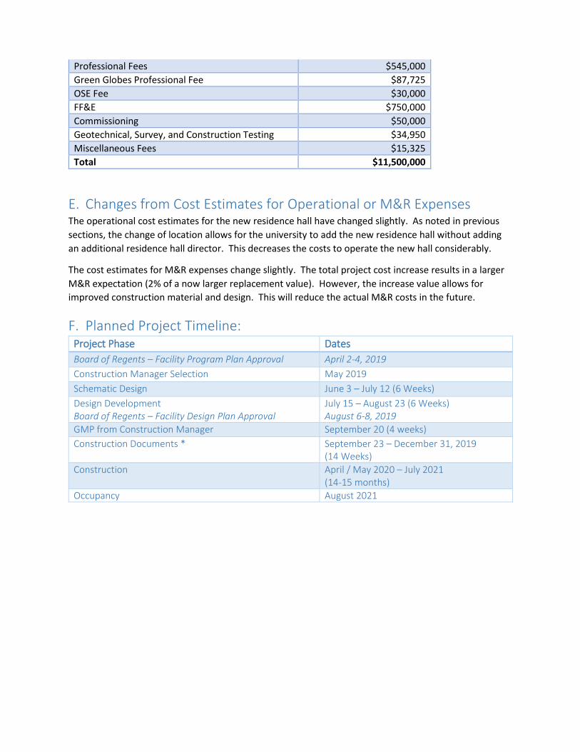
Professional Fees $545,000
Green Globes Professional Fee $87,725
OSE Fee $30,000
FF&E $750,000
Commissioning $50,000
Geotechnical, Survey, and Construction Testing $34,950
Miscellaneous Fees $15,325
Total $11,500,000
E. Changes from Cost Estimates for Operational or M&R Expenses The operational cost estimates for the new residence hall have changed slightly. As noted in previous
sections, the change of location allows for the university to add the new residence hall without adding
an additional residence hall director. This decreases the costs to operate the new hall considerably.
The cost estimates for M&R expenses change slightly. The total project cost increase results in a larger
M&R expectation (2% of a now larger replacement value). However, the increase value allows for
improved construction material and design. This will reduce the actual M&R costs in the future.
F. Planned Project Timeline: Project Phase Dates
Board of Regents – Facility Program Plan Approval April 2-4, 2019
Construction Manager Selection May 2019
Schematic Design June 3 – July 12 (6 Weeks)
Design Development Board of Regents – Facility Design Plan Approval
July 15 – August 23 (6 Weeks) August 6-8, 2019
GMP from Construction Manager September 20 (4 weeks)
Construction Documents * September 23 – December 31, 2019 (14 Weeks)
Construction April / May 2020 – July 2021 (14-15 months)
Occupancy August 2021

Attachment I – Site Plan:
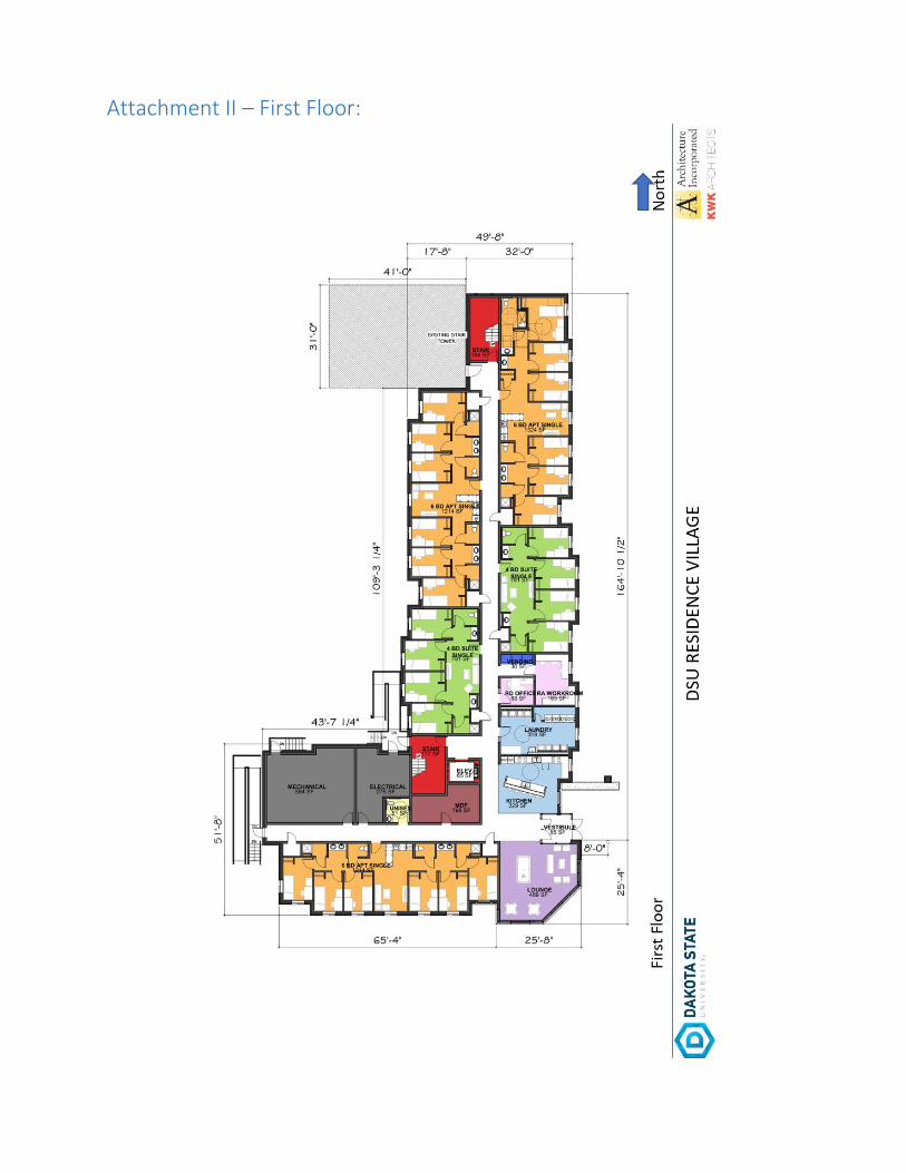
Attachment II – First Floor:
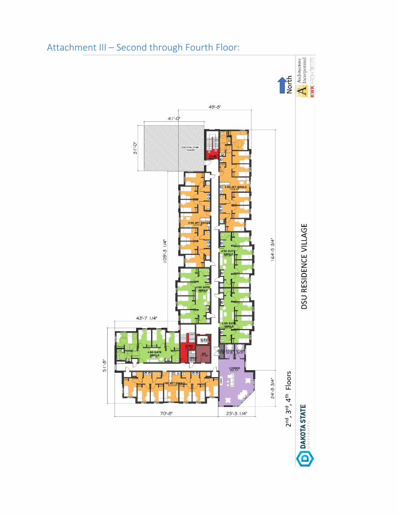
Attachment III – Second through Fourth Floor:
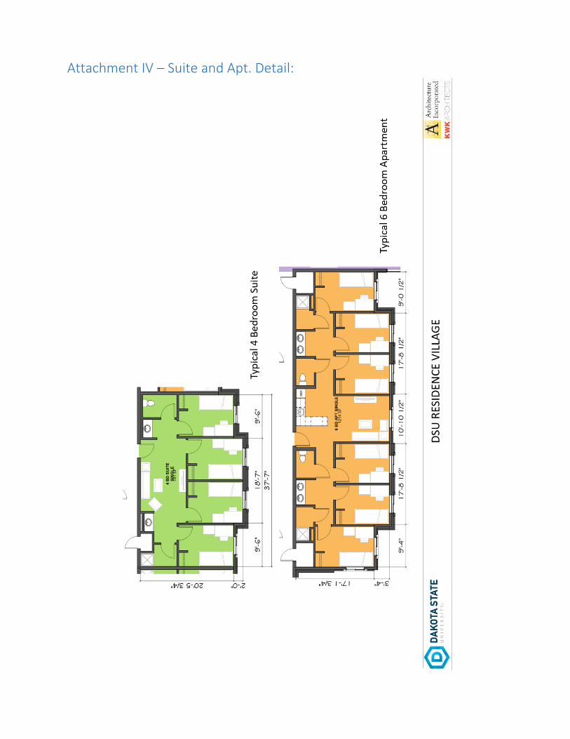
Attachment IV – Suite and Apt. Detail:

Attachment V – Aerial Views: