Daewoo+XG-332V,+334V,+335V,+336V
31
Service Manual S/N No. : FEB. 2004 DAEWOO DAT CO., LTD. Mini Component System Model: XG-332V, 334V[K], 335V[K]/336V[K] 9CD8303800 XG-332V/334V/335V/336V XG-334VK/335VK/336VK Feb. 2005 33xVK MIC MIC VOL 33xVK
-
Upload
fingersound -
Category
Documents
-
view
51 -
download
0
Transcript of Daewoo+XG-332V,+334V,+335V,+336V
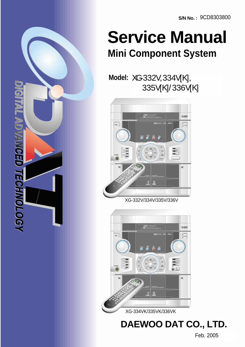
Service ManualS/N No. :
FEB. 2004DAEWOO DAT CO., LTD.
Mini Component System
Model: XG-332V, 334V[K],335V[K]/336V[K]
9CD8303800
XG-332V/334V/335V/336V
XG-334VK/335VK/336VK
Feb. 2005
33xVK
MIC
MIC VOL
33xVK

SAFETY PRECAUTIONS ................................................................................... 1
ADJUSTMENTS .................................................................................................. 3
EXPLODED VIEW AND PARTS LIST .............................................................. 5/6
WIRING DIAGRAM .......................................................................................... 7/8
BLOCK DIAGRAM ......................................................................................... 9/10
SCHEMATIC DIAGRAM ............................................................................... 11/20MAIN Section ...................................................................................................... 11/12TUNER Section .................................................................................................. 13/14TAPE Section ...................................................................................................... 15/16FRONT Section ........................................................................................................ 17MP3/VCD Section .................................................................................................... 18KARAOKE Section ................................................................................................... 19POWER Section ...................................................................................................... 20
PCB PATTERN LAYOUT .............................................................................. 21/29MAIN ................................................................................................................... 21/24FRONT ..................................................................................................................... 25MP3/VCD ................................................................................................................. 26KARAOKE ................................................................................................................ 27POWER .............................................................................................................. 28/29
ELECTRICAL PART LIST ...................................................................... Appendix
Table of Contents
MINI COMPONENT SYSTEMXG-332V
XG-334V[K]XG-335V[K]XG-336V[K]
Safety Precautions
1
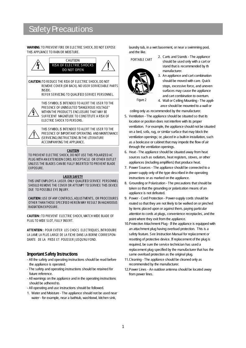
WARNING: TO PREVENT FIRE OR ELECTRIC SHOCK, DO NOT EXPOSE THIS APPLIANCE TO RAIN OR MOISTURE.
CAUTION :TO REDUCE THE RISK OF ELECTRIC SHOCK, DO NOTREMOVE COVER (OR BACK). NO USER SERVICEABLE PARTS INSIDE.REFER SERVICING TO QUALIFIED SERVICE PERSONNEL.
THIS SYMBOL IS INTENDED TO ALERT THE USER TO THE PRESENCE OF UNINSULTED "DANGEROUS VOLTAGE"
WITHIN THE PRODUCT'S ENCLOSURE THAT MAY BE SUFFICIENT MAGNITUDE TO CONSTITUTE A RISK OF ELECTRIC SHOCK TO PERSONS.
THIS SYMBOL IS INTENDED TO ALERT THE USER TO THEPRESENCE OF IMPORTANT OPERATING AND MAINTENANCE (SERVICING) INSTRUCTIONS IN THE LITERATURE ACCOMPANYING THE APPLIANCE.
CAUTION TO PREVENT ELECTRIC SHOCK, DO NOT USE THIS POLARIZED AC PLUG WITH AN EXTENSION CORD, RECEPTACLE OR OTHER OUTLET UNLESS THE BLADES CAN BE FULLY INSERTED TO PREVENT BLADE EXPOSURE.
LASER SAFETY THIS UNIT EMPLOYS A LASER. ONLY QUALIFIED SERVICE PERSONNEL SHOULD REMOVE THE COVER OR ATTEMPT TO SERVICE THIS DEVICE DUE TO POSSIBLE EYE INJURY.
CAUTION : USE OF ANY CONTROLS, ADJUSTMENTS, OR PROCEDURES OTHER THAN THOSE SPECIFIED HEREIN MAY RESULT IN HAZARDOUS RADIATION EXPOSURE.
CAUTION : TO PREVENT ELECTRIC SHOCK, MATCH WIDE BLADE OF PLUG TO WIDE SLOT, FULLY INSERT.
ATTENTION : POUR EVITER LES CHOCS ELECTRIQUES, INTRODUIRE LA LAME LA PLUS LARGE DE LA FICHE DANS LA BORNE CORRESPON-DANTE DE LA PRISE ET POUSSER JUSQU'AU FOND.
Important Safety Instructions- All the safety and operating instructions should be read before
the appliance is operated.- The safety and operating instructions should be retained for
future reference.- All warnings on the appliance and in the operating instructions
should be adhered to.- All operating and use instructions should be followed.
1. Water and Moisture - The appliance should not be used near water - for example, near a bathtub, washbowl, kitchen sink,
laundry tub, in a wet basement, or near a swimming pool,and the like.
2. Carts and Stands - The applianceshould be used only with a cart orstand that is recommended by thmanufacturer.
3. An appliance and cart combination
should be moved with care. Quick
stops, excessive force, and unevensurfaces may cause the appliance
and cart combination to overturn.4. Wall or Ceiling Mounting - The appli-
ance should be mounted to a wall or
ceiling only as recommended by the manufacturer.
5. Ventilation - The appliance should be situated so that its
location or position does not interfere with its proper
ventilation. For example, the appliance should not be situated
on a bed, sofa, rug, or similar surface that may block the
ventilation openings; or, placed in a built-in installation, such
as a bookcase or cabinet that may impede the flow of air through the ventilation openings.
6. Heat - The appliance should be situated away from heat
sources such as radiators, heat registers, stoves, or other
appliances (including amplifiers) that produce heat.
7. Power Sources - The appliance should be connected to a
power supply only of the type described in the operating
instructions or as marked on the appliance.
8. Grounding or Polarization - The precautions that should be
taken so that the grounding or polarization means of an appliance is not defeated.
9. Power - Cord Protection - Power-supply cords should be
routed so that they are not likely to be walked on or pinched
by items placed upon or against them, paying particular
attention to cords at plugs, convenience receptacles, and the
point where they exit from the appliance.10.Protective Attachment Plug - If the appliance is equipped with
an attachment plug having overload protection. This is a
safety feature. See Instruction Manual for replacement or
resetting of protective device. If replacement of the plug is
required, be sure the service technician has used a
replacement plug specified by the manufacturer that has the same overload protection as the original plug.
11.Cleaning - The appliance should be cleaned only as recommended by the manufacturer.
12.Power Lines - An outdoor antenna should be located away from power lines.
CAUTIONRISK OF ELECTRIC SHOCKS
DO NOT OPEN
PORTABLE CART
Figure 2

Safety Precautions
2
13.Outdoor Antenna Grounding - If an outside antenna is
connected to the receiver be sure the antenna system is grounded so as to provide some protection against voltage
surges and built-up static charges. Article 810 of the National
Electrical Code, ANSI/NFPA 70, provides information with
regard to proper grounding of the mast and supportingstructure, grounding of the lead-in wire to an antenna-discharge unit, size of grounding conductors,location of antenna-discharge unit, connection to grounding electrodes and requirements for the grounding electrode. See Figure 1.
14.Non-use Periods - The power cord of the appliance should be
unplugged from the outlet when left unused for a long period of time.
15.Object and Liquid Entry - Care should be taken so that objects do not fall and liquids are not spilled into the enclosure through openings.
16.Damage Requiring Service - The appliance should be serviced by qualified service personnel when:
a) The power-supply cord or the plug has been damaged; or
b) Objects have fallen, or liquid has been spilled into the appliance; or c) The appliance has been exposed to rain; or
d) The appliance does not appear to operate normally or
exhibits a marked change in performance; or
e) The appliance has been dropped, or the enclosure damaged.
17.Servicing - The user should not attempt to service the appliance beyond that described in the operating instructions.
All other servicing should be referred to qualified service personnel.
ANTENNA DISCHARGE UNIT(NEC SECTION 810-20)
ANTENNA LEADIN WIRE
POWER SERVICE GROUNDINGELECTRODE SYSTEM(NEC ART 250 PART H)
GROUND CLAMP
ELECTRICSERVICEEQUIPMENT
GROUNDING CONDUCTORS(NEC SECTION 810-21)
GROUND CLAMPS
EXAMPLE OF ANTENNA GROUNDING
NEC - NATIONAL ELECTRICAL CODE

Adjustments
3

Adjustments
4

Exploded View and Mechanical Parts List
5

Exploded View and Mechanical Parts List
6
No. Part Name Part Code Description Q'ty
41 HOLDER AC CORD 9CD2303300 ABS 1
42 COVER ANT 9CD0410400 ABS 1
43-1 HEAT SINK 10 9CD4404500 AL 1
43-2 HEAT SINK N30 9CD4406200 AL 1
43-3 HEAT SINK N50 9CD4405800 AL 1
43-4 HEAT SINK N65 9CD4408200 AL 1
44 BRACKET HEAT TR 9CD2414600 SECC 1.0T 2
45 BRACKET HEAT TR 9CD2414600 SUS 0.5T 1
46 KNOB MIC 9CD1332000 MIPS 1
47 BRACKET MIC PCB 9CD2415500 SECC 1.0T 1
48 GUIDE FLT 9CD2506500 ABS 1
332 334 335 336
S1 SCREW TAPTTITE 7173261011 TT2 BIN 2.6 X 10 MFZN 16 16 16 16
S2 SCREW TAPTTITE 7173301011 TT2 BIN 3.0X10 MFZN 16 15 15 15
S3 SCREW TAPTTITE 7173301212 TT2 BIN 3.0X12 BK 21 21 21 21
S4 SCREW TAPTTITE 7173301612 TT2 BIN 3.0X16 BK 2 2 2 2
S5 SCREW TAPTTITE 7173300411 TT2 BIN 3.0X6 MFZN 5 8 8 8
S6 SCREW TAPTTITE 7173301411 TT2 BIN 3.0X14 MFZN * 4 4 4
S7 SCREW TAPTTITE 7173400611 TT2 BIN 4.0X6 MFZN * 4 4 4
S8 SCREW TAPTTITE 7173401011 TT2 BIN 4.0X10 MFZN 4 * * *
S9 WASHER SCREW 9CD3102401 TT2 BIN 3.0X8 + D12 1 * * *
S10 WASHER SCREW 9CD3102400 TT2 BIN 3.0X10 + D14 1 1 1 1
W1 WASHER PLAIN 1 * * *
No. Q'ty
P1 1
P2 1
P3 1
P4 1
P5 1
P6 1
P7 1
option
option
Q'tyNo.
Part Name
PCB FRONT
PCB MAIN
PCB POWER
DescriptionPart CodeScrew Type
PCB JACK
PCB MIC
PCB CD
PCB MP3
334
335
336
334/335/336
option
332/334/335/336
Remark
334/335/336
332
option
option
332
No. Part Name Part Code Description Q'ty
1 WINDOW DOOR A 9CD16206A0 ACRYL 1
2 WINDOW DOOR B 9CD16206B0 ACRYL 1
3 DOOR CASS A 9CD18141A0 HIPS 1
4 DOOR CASS B 9CD18141B0 HIPS 1
5 SRING DOOR EJECT L 9CD30080L0 STS 0.9 1
6 SRING DOOR EJECT R 9CD30080R0 STS 0.9 1
7 DOOR FRAME A 9CD18113A0 MIPS 1
8 DOOR FRAME B 9CD18113B0 MIPS 1
9 CUSHION FOOT 9CD4207700 URETHAN 2
10-A DAMPER GEAR B 9CD2603200 ACETAL 2
10-B DAMPER BASE B 9CD2603300 ABS 2
11-A LOCKER BASE 9CDOB01900 ABS 2
11-B LOCKER CAM 9CDOB02000 ABS 2
11-C LOCKER SPRING 9CDOB01600 STS 2
12 BRKT SIDE 9CD2412900 ABS 2
13 KNOB POWER 9CD1350100 HIPS 1
14 LENS POWER 9CD1620900 ACRYL 1
15 KNOB OPEN 9CD1350200 HIPS 1
16 KNOB EQ 9CD1350700 HIPS 1
17 KNOB DISC 9CD1350800 HIPS 1
18 KNOB FUNCTION 9CD1351000 ACRYL 1
19 PLATE FILTER 9CD0913200 MIPS 1
20 GUIDE FUNCTION 9CD2507800 HIPS 1
21 KNOB CAP 9CD1350600 HIPS 1
22 DECO KNOB CAP 9CD1005200 ABS 1
23 KNOB PRESET 9CD1350900 HIPS 1
24 DECO KNOB PRESET 9CD1005300 ABS 2
25 KNOB TUNING 9CD1350400 HIPS 1
25-1 KNOB JOG 9CD1350300 HIPS 1
26 DECO RING VR 9CD1005100 ACRYL 2
27 KNOB VR 9CD1350500 HIPS 1
28 DECO RING PRESET 9CD1005400 ACRYL 1
29 WINDOW FLT 9CD1620700 ACRYL 1
30 CD DECK MECHA 9CD6012900 DCC-01DA 1
31 DOOR CD 9CD1814200 HIPS 1
32 WINDOW CD DOOR 9CD1620800 ACRYL 1
33 PANEL FRONT 9CD0312200 HIPS 1
34 BADGE DAEWOO 9CD1500900 ABS 1
35-A CASSETTE DECK LOGIC 9CD6010000 1
35-B CASSETTE DECK LOGIC 9CD6010100 1
36 COVER TOP 9CD0411400 MIPS 1
37 COVER SIDE L 9CD04115L0 MIPS 1
38 COVER SIDE R 9CD04115R0 MIPS 1
39-1 CHASSIS BOTTOM 9CD0607500 ABS 1
39-2 CHASSIS BOTTOM 9CD0607100 SECC 1.0T 1
40 COVER BACK 9CD0409800 MIPS 1
CR COATING
CR COATING
332/334/335/336
option
332 option
334/335/336 option
332
334/335/336
332/334/335/336
Remark

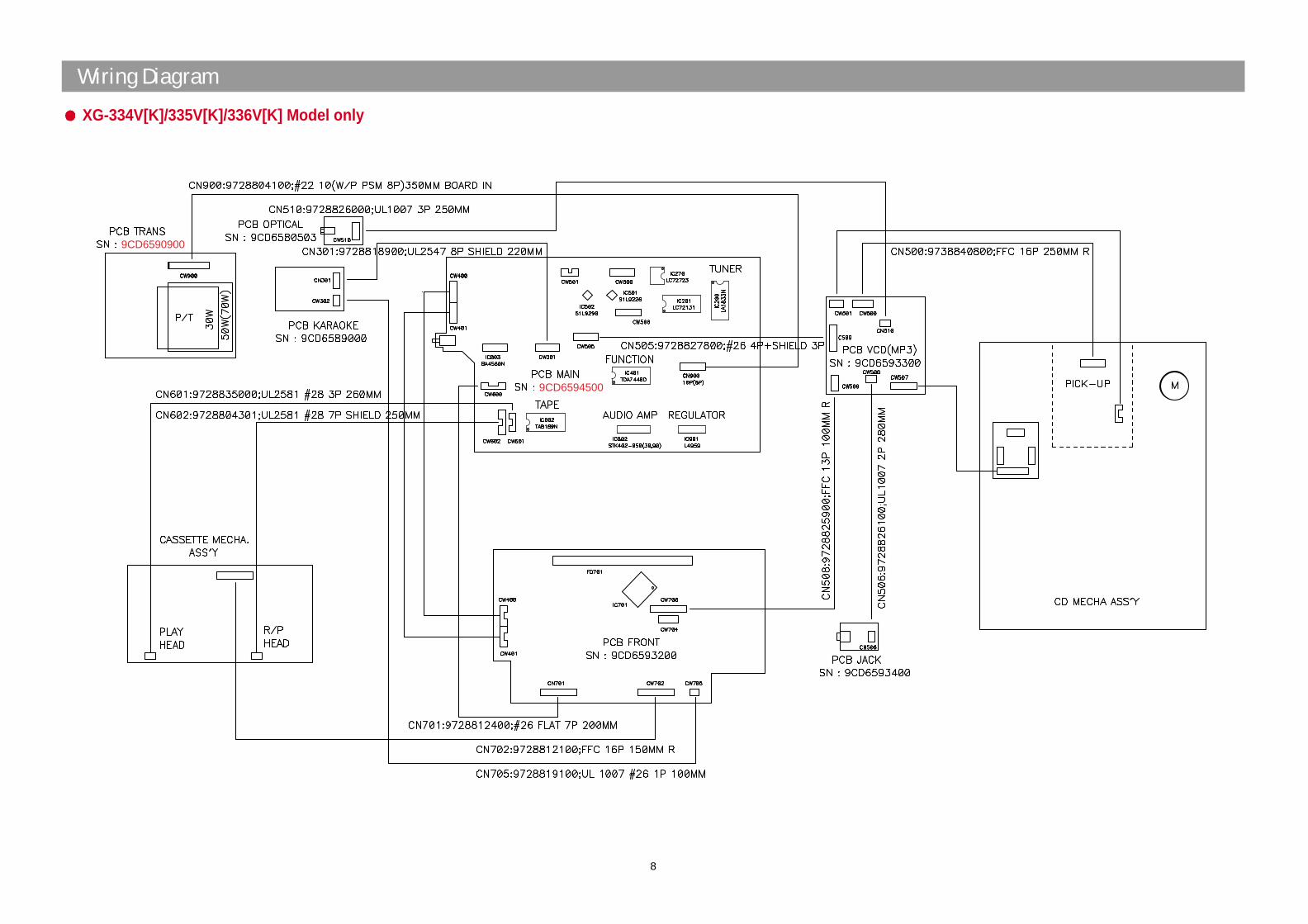
Wiring Diagram
7
XG-332V Model only
Wiring Diagram
8
9CD6590900
9CD6594500
XG-334V[K]/335V[K]/336V[K] Model only
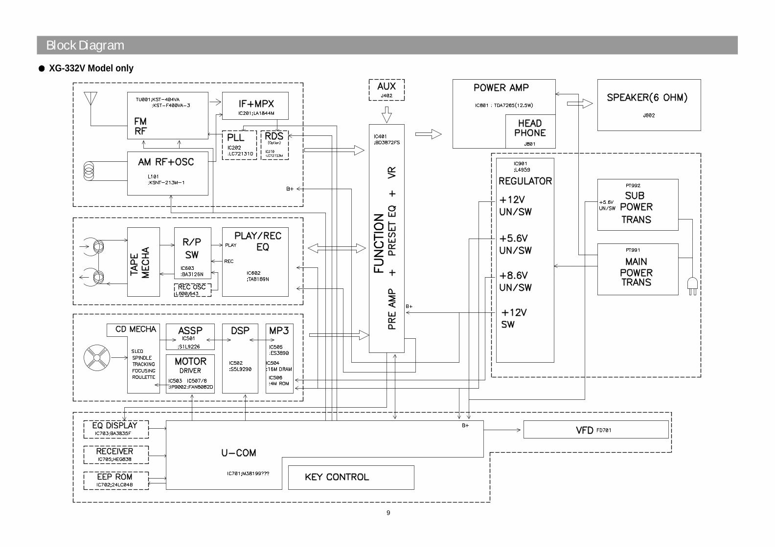
Block Diagram
9
XG-332V Model only

Block Diagram
10
XG-334V[K]/335V[K]/336V[K] Model only

Schematic Diagram
11
MAIN/POWER Section : XG-332V Model only
0dB¡›-87dB-¡˜
0dB¡›-87dB-¡˜

Schematic Diagram
12
MAIN Section : XG-334V[K]/335V[K]/336V[K] Models only

4.8 #3
23 24
#5
12
2.5
13 14
0
15
0
16
0
17 18
#1
19
#2
20
#3
21
#4
22
N.C 0 0
CE
X
MJ
X
O
X X
O
O
O
#7 ? #6 #7 #8 2.5
00
012 5
CE
O
1K
X
O
X
OO
JW
XX
X X
6 7 8 9 12 1 2 3 4 5 6 7 8 9 10 11
CE X O O O
IC201 13 14 15
2.1 4.8 2.1
16 17 18 19
2.1 GND #2#1
20 21 22
#4
IC202
2 GANG
N.C
322
VCC E(1) 12 12
22K
S-AM 270
FTZ MS3
322
SEMP
X
X
470pF
12K12K
O
O
2.13.2 3.2 2.1 2.1 4.5 #6 4.8#8 #9
3 & 4 GANG
#5 N.C
324/325
#8 : VT
1.1VCC GND
Vtg(V)B(3)C(2) 12
0GND BASIC : FM
S-AM 18K
FTZ
HR202
22K
S-AM
FTZ
MS3MS2
47
HR003
CF001
SEMP
CE & SEMP
FTZ
X
O
L201 L202
OO
O
HR215 HR219
102 pF
102 pF
HC203 HC214
33K33K
JW
R218
XX
HR220
X
JW204
HC215 HC216
1 2 3 4 5 10 11 Name Name Q003 Q104 IC205 REMARK
47
324/325
X O
#8 : FM(0.6V), AM(2.3V)
#5 : FM(4.1V), AM(3.0V)
Pin No.
Vtg(V) 4.8
#7 : FM(2.4V), AM(0V)
#4 : FM(0), AM(12)
Pin No.
Vtg(V)
12K
270 OHM
15K
27K
HR212/213
3-Gang
#2 : STEREO(0V) MONO(5V)
#9 : FM(?V), AM(?V)
#6 : FM(0V), AM(1.3V)#7 : FM(3.6V), AM(1.0V)
Vtg(V) 3.5
#4 : FM(4V), AM(2.6V)
MAIN GND
HR003
#5 : TUNING ON(VCC) TUNING OFF(0V) #6 : FM(0V), AM(2.4V)
#1 : FM(3.7), AM(0)
1.1Vtg(V)
5.6K
47 OHM
15K
HR203
10K
R217
MS3MS2
HR214
CF002
R217/218
2.7K
2-Gang
TU001
4-Gang
JW205
HC217
#1 : SD ON(0V) OTHERWISE(5V)
#3 : NORMAL(V=< 0.5V ) MUTE(1.4V=<V=<2.2V) SEEK(V>=3.5V)
Pin No.
#3 : FM(3.7), AM(0)
#2 : TUNING ON(VCC) TUNING OFF(0V) #2 : TUNING ON(VCC) TUNING OFF(0V)
Pin No.
R204B
Q001
18K
3
56 94
14
13
1
10
8 7 1211
2
6
5
3
2
41 7
9
8 13
11 14
1210
Schematic Diagram
13
TUNER Section : XG-332V Model only

Schematic Diagram
14
TUNER Section : XG-334V[K]/335V[K]/336V[K] Models only

ALC
Schematic Diagram
15
TAPE Section : XG-332V Model only

Schematic Diagram
16
TAPE Section : XG-334V[K]/335V[K]/336V[K] Models only

Schematic Diagram
17
FRONT Section

Schematic Diagram
18
MP3/VCD Section

Schematic Diagram
19
KARAOKE Section : XG-334VK/335VK/336VK Karaoke Models only

Schematic Diagram
20
POWER Section : XG-334V[K]/335V[K]/336V[K] Models only

P.C.B Pattern Layout
21
MAIN <Top View> : XG-332V Model only

P.C.B Pattern Layout
22
MAIN <Bottom View> : XG-332V Model only

P.C.B Pattern Layout
23
MAIN <Top View> : XG-334V[K]/335V[K]/336V[K] Models only

P.C.B Pattern Layout
24
MAIN <Bottom View> : XG-334V[K]/335V[K]/336V[K] Models only

P.C.B Pattern LayoutFRONT
25

P.C.B Pattern LayoutMP3/VCD
26
<Top View> <Bottom View>

P.C.B Pattern LayoutKARAOKE : Karaoke Model Only - XG-334V[K]/335V[K]/336V[K]
27

P.C.B Pattern Layout
28
POWER : XG-332V, CE Region only POWER : XG-332V, Other Region only
P.C.B Pattern Layout
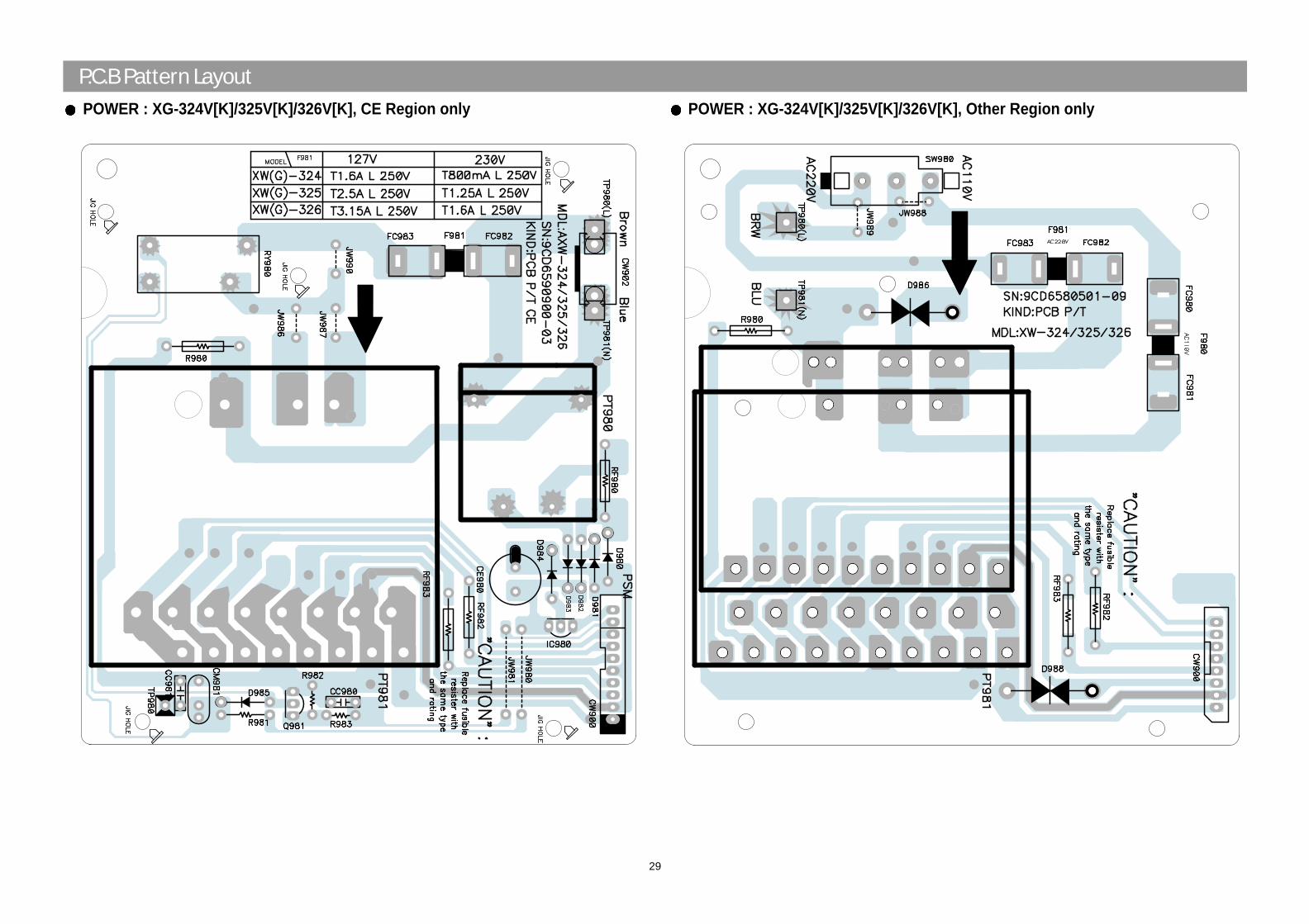
29
POWER : XG-324V[K]/325V[K]/326V[K], CE Region only POWER : XG-324V[K]/325V[K]/326V[K], Other Region only