
DAC 8 DSD - ta-hifi.de · 23.12.2015 V 1.01 Minor corrections 26.01.2016 V 1.10 Service Modes 11,...
21
DAC 8 DSD RS 232 Control (c) T+A elektroakustik GmbH&Co KG – Herford – Germany Version 1.12 02.06.2016
Transcript of DAC 8 DSD - ta-hifi.de · 23.12.2015 V 1.01 Minor corrections 26.01.2016 V 1.10 Service Modes 11,...

DAC 8 DSDRS 232 Control
(c) T+A elektroakustik GmbH&Co KG – Herford – Germany Version 1.12 02.06.2016

Document History
22.12.2015 V 1.00 Document released
23.12.2015 V 1.01 Minor corrections
26.01.2016 V 1.10 Service Modes 11, 97, 98 added
31.05.2016 V 1.11 Firmware version requirements for Service Modes 11, 97, 98 added
02.06.2016 V 1.12 Corrected brightness level range to 0...8 for DAC8DSD

CONTENTS
0 GENERAL
1 HARDWARE
2 PROTOCOL
2.1 Physical layer
2.2 Data Link Layer
2.3 Application Layer
3 COMMANDS
3.1 Command Overview
3.2 Command Details
4 RESPONSES
4.1 Prompt
4.2 Query Responses
4.3 Query Response Format
5 NOTIFICATIONS
5.1 Error Notifications
5.2 Status Notifications
5.3 Notification Level
6 FIRST STEPS

General
This document defines a simple ASCII-based (but 8 bit) control interface via RS-232C with the following properties:
· Simple enough to be emulated by any terminal program· Readable command names· Numbers in commands transferred as ASCII strings not as binary data· Notifications about the current settings and state of DAC 8 transmitted as ASCII strings or binary data· Asymmetric at the application layer (commands vs. response / notification)· Asymmetric at the data link layer (one-sided flow control only)· No error protection
The control interface can be used to control a DAC 8 from a PC or any other ControlPoint equipped with aRS232 interface. USB to RS232 converters can be used if the ControlPoint does not provide a RS232 interface.
1 Hardware
The control interface uses a RS232 type of interface. The socket on the rear panel of the DAC 8 is a RJ12socket with the following pinning:
Pinout DAC_8 / RS232 adapter cable
Pin No. (RJ-12)Pin No.
(Sub-D 9 - female)Signal
2 5 GND
3 2 RxD (DAC_8 → PC)
5 3 TxD (PC → DAC_8)
1 NC DAC_8 Trigger Out (+5V)
Notes:
For easy connection an adapter RJ-12 → SUB-D 9 (female) can be obtained from T+A as an accessory.
In case the controlling device (PC) does not feature a RS232 interface, a standard USB/RS232 converter can be used.
Pin 1 of the RJ12 socket carries a +5V trigger voltage that is high when DAC_8 is powered ON.
This trigger voltage can be used to turn an extrernal device (e.g. amplifier) ON.

2 Protocol
2.1 Physical Layer
Bidirectional communication by RS-232C lines TxD and RxD (no control lines used)
Port settings: Baud rate: 38400, 8 bit, no parity, 1 stop bit
2.2 Data Link Layer
The data link layer uses an asymmetric, connectionless and line-oriented protocol.
The DAC 8 will echo received characters. The echo can be turned off by sending an „ECHO OFF“ command.
Information from the DAC 8 is sent as message lines of max. 32 8-bit characters. Every message is terminated by a CR/LF combination.
jIf Hyper terminal is used: Check the ASCII setup and activate the setting “Send line ends with line feeds”.
Flow Control
The DAC 8 will read in an entire data line of max. 32 8-bit ASCII characters, terminated by a termination character sequence CR/LF (0x0D, 0x0A). As soon as a line termination character sequence has been received the received data will be interpreted and executed by the DAC 8.
After processing the received data and when ready for a new command the DAC 8 will send a prompt character >
After receiving the prompt character, the ControlPoint may send the next command.
2.3 Application Layer
The application layer transfers messages. The message types "command", "response" and "notification" exist. This classification has no effect on the notation of the messages. It describes only the functionality of the messages sent to or received from the device.
Commands are properly formatted ASCII strings sent from a ControlPoint to the DAC 8.
Responses are messages sent from DAC 8 to the ControlPoint as a response to a query sent by the ControlPoint.
Notifications are messages generated by the DAC 8 to inform the ControlPoint about changed device settings or in case of errors. Notifications can be set to different formats (ASCII or binary) or can be turnedOFF completely.
Note:
If notifications are turned ON, the ControlPoint is automatically informed about all changes in device settings (changed inputs, changed volume level etc.), about errors and about or changes in the audio datastream received (sample rate changes etc.).
Instead of automatic notification the ControlPoint can also query device settings and status information from the DAC 8 and will receive the requested information as response to the query.

3 Commands
A command is a string of 8 bit ASCII characters consisting of a command ID followed by one or more parameters. A command is terminated by a CR/LF (carriage return / line feed) sequence. String length is max. 32 characters. Command ID and parameters are separated by spaces (0x20).
Commands are not case-sensitive (i.e.: the commands „POWER ON“, „Power On“, „power on“ will have the same effect).
For some commands short forms exist (ex. „VOL“ instead of „VOLUME“)
All DAC 8 commands are described in detail in this chapter.
3.1 Command Overview
Command ID
ID (short form)
Parameter(s) Example Comment RS 232Version
POWER PWR [ON / OFF / ?] POWER ON Switches DAC 8 ON 1.0
INPUT I [1...8 / ?] INPUT 7 Selects Input no. 7 (AES/EBU) 1.0
VOLUME V {RAMP} [0...64 / ?] VOL RAMP 50 Ramps VOLUME to 50 1.0
OVS [1...4 / ?] OVS 3 Selects Oversampling no. 3 (Bezier 1) 1.0
INV [ON / OFF / ?] INV ON Turns INVERT function ON 1.0
WIDE [ON / OFF / ?] WIDE ? Returns WIDE Status 1.0
MUTE [ON / OFF / ?] MUTE ON Switches analogue outputs OFF 1.0
ECHO [ON / OFF / ?] ECHO OFF Turns RS232 ECHO OFF 1.0
NOTIFY NTF [0, 1, 2, / ?] NOTIFY 2 Selects „All Notifications ON“ mode 1.0
STATUS S [?] STATUS ? Returns the current operation status and device settings
1.0
LED L [?] Returns current LED state as ASCII string. 1.0
RATE R [?] Returns current sample rate as ASCII string.
1.0
BRIGHTNESS BRT [0...8] BRT 4 Sets display brightness to 50% 1.0
VER [?] VER ? Returns the current RS 232 Version 1.0
Notes:1.) Required parameters are enclosed in squared brackets ([…]).
2.) Parameters in curly braces ({ }) are optional.
3.) The column „ID (short form) contains alternative short commands (i.e. „POWER ON“ will have the same effect as „PWR ON“).
4.) The column “RS232 Version” contains the DAC 8 firmware version since the command is available.

3.2 Command Details
3.2.1 POWER
This command switches the Device ON or OFF or queries the current power state.
Format: POWER [ON / OFF / ?]
Examples:Query current power state: POWER ? or (short form): PWR ?Turn device ON: POWER ON or (short form): PWR ONTurn device OFF: POWER OFF or (short form): PWR OFF
ID Parameter(s) Comment
POWER
orPWR
[ON / OFF / ?] Switch or query the current power state.
ON Turn device ON
OFF Turn device OFF
? Query current power state
3.2.2 INPUT
This command is used to select one of the eight digital inputs or to query the currenly selected input.
Format: INPUT [1...9]
Examples:Select input 1 (=S/P-DIF 1): INPUT 1 or (short form): INP 1Query current input: INPUT ? or (short form): INP ?
ID Parameter(s) Comment
INPUT
orINP
[1 … 9] Switch or query the current input.
1 Select input 1 = S/P-DIF 1
2 Select input 2 = S/P-DIF 2
3 Select input 3 = S/P-DIF 3
4 Select input 4 = S/P-DIF 4
5 Select input 5 = OPTical S/P-DIF Input (TOS-Link)
6 Select input 6 = BNC
7 Select input 7 = AES-EBU
8 Select input 8 = SYS – Input (DAC 8 DSD only)
9 Select input 9 = USB
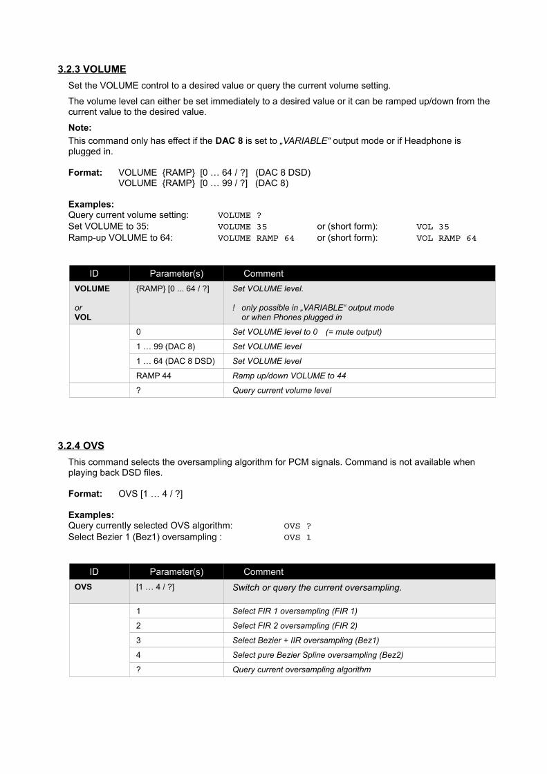
3.2.3 VOLUME
Set the VOLUME control to a desired value or query the current volume setting.
The volume level can either be set immediately to a desired value or it can be ramped up/down from the current value to the desired value.
Note:
This command only has effect if the DAC 8 is set to „VARIABLE“ output mode or if Headphone is plugged in.
Format: VOLUME {RAMP} [0 … 64 / ?] (DAC 8 DSD)VOLUME {RAMP} [0 … 99 / ?] (DAC 8)
Examples:Query current volume setting: VOLUME ?Set VOLUME to 35: VOLUME 35 or (short form): VOL 35Ramp-up VOLUME to 64: VOLUME RAMP 64 or (short form): VOL RAMP 64
ID Parameter(s) Comment
VOLUME
orVOL
{RAMP} [0 ... 64 / ?] Set VOLUME level.
! only possible in „VARIABLE“ output mode or when Phones plugged in
0 Set VOLUME level to 0 (= mute output)
1 … 99 (DAC 8) Set VOLUME level
1 … 64 (DAC 8 DSD) Set VOLUME level
RAMP 44 Ramp up/down VOLUME to 44
? Query current volume level
3.2.4 OVS
This command selects the oversampling algorithm for PCM signals. Command is not available when playing back DSD files.
Format: OVS [1 … 4 / ?]
Examples:Query currently selected OVS algorithm: OVS ?Select Bezier 1 (Bez1) oversampling : OVS 1
ID Parameter(s) Comment
OVS [1 … 4 / ?] Switch or query the current oversampling.
1 Select FIR 1 oversampling (FIR 1)
2 Select FIR 2 oversampling (FIR 2)
3 Select Bezier + IIR oversampling (Bez1)
4 Select pure Bezier Spline oversampling (Bez2)
? Query current oversampling algorithm

3.2.5 INV
This command switches the absolute phase inversion ON or OFF or queries the current inversion state.
Format: INV [ON / OFF / ?]
Examples:Query current inversion state: INV ?Select inverted absolute phase : INV ON
ID Parameter(s) Comment
INV [ON / OFF / ?] Switch or query the current phase setting.
ON Select inverted phase
OFF Select non-inverted phase
? Query current phase setting
3.2.6 WIDE
This command switches the analogue reconstruction filters of the DAC 8 to NORMAL (CLEAN) or WIDE bandwidth mode or queries the current bandwidth state.
Format: WIDE [ON / OFF / ?]
Examples:Query current bandwidth state: WIDE ?Select normal bandwidth: WIDE OFF
ID Parameter(s) Comment
WIDE [ON / OFF / ?] Switch or query the current analogue bandwidth.
ON Select WIDE bandwidth mode
OFF Select NORMAL bandwidth mode (CLEAN)
? Query current bandwidth setting
3.2.7 MUTE
This command switches the analogue outputs ON or OFF or queries the current output state.
Format: MUTE [ON / OFF / ?]
Examples:Query current mute state: MUTE ?Switch muting ON (=outputs OFF): MUTE ON
ID Parameter(s) Comment
MUTE [ON / OFF / ?] Switch or query the muting state.
ON Switch muting ON (= outputs OFF)
OFF Switch muting OFF (= outputs ON)
? Query current muting state

3.2.8 BRIGHTNESS
This command sets or queries the brightness of the display and LEDs of the DAC 8.
Format: BRIGHTNESS [1 … 10 / ?] (DAC 8)
BRIGHTNESS [1 … 8 / ?] (DAC 8 DSD)
Example:Set the brightness to 80% : BRIGHTNESS 8
ID Parameter(s) Comment
BRIGHTNESS
orBRT
[0 … 10 / ?]
[0 … 8 / ?]
Switch or query the current display brightness.
0 Switch the display OFF
1 … 10 (DAC 8) Set the brightness to 0 .. 100 % in 10% increments
1 … 8 (DAC 8 DSD) Set the brightness to 0 .. 100 % in 12.5% increments
? Query current display brightness
3.2.6 STATUS
This command queries the current operating state of DAC 8.DAC 8 will return Input Number ($INP:), Sample Rate ($SRT:), Volume Setting ($VOL:) and LED state ($LED:)The STATUS query is a short form of the query sequence INP ?, RATE ?, VOL ?, LED ?
Format: STATUS [ ? ]
Examples:Query current DAC 8 state: STATUS ?Short form: S ?
ID Parameter(s) Comment
STATUS
orS
[?] Query the current DAC 8 operating state.
? Query current DAC 8 state.
DAC 8 response: Input_No., Sample_Rate, Volume, LED_State

3.2.9 ECHO
This command switches the echo function for the RS232 interface ON or OFF or queries the current state.
If ECHO is set to „ON“ all characters sent to DAC 8 via the RS232 interface are echoed. This is useful when sendingcommands to the DAC 8 from a PC terminal program (like Hyperterm). The characters sent to the DAC 8 are then displayed in the terminal window on the PC.
When DAC 8 is controlled from a home automation system the echo function is normally not needed or the echoed characters might even interfere with the control system. In such cases the echo can be switched OFF.
Switching OFF the echo also minimizes traffic on the RS232 interface which increases performance and throughput.
After power-on the echo function is always set to ON.
It is recommended to switch it OFF after powering on the DAC 8 by sending a „ECHO OFF“ command.
Format: ECHO [ON / OFF / ?]
Examples:Query current echo state: ECHO ?Switch echo function OFF: ECHO OFF
ID Parameter(s) Comment
ECHO [ON / OFF / ?] Switch or query the muting state.
ON Switch echo function ON (= Terminal Mode)
OFF Switch echo function OFF
? Query current echo state
3.2.10 NOTIFY
This command sets or queries the current notification level.
Format: NOTIFY [0 / 1 / 2 / ?]
Examples:Query currently selected OVS algorithm: NOTIFY ?Select (ASCII) string notification mode: NOTIFY 2
ID Parameter(s) Comment
NOTIFY [0 … 2 / ?] Switch or query the current notification level.
0 Switch all notifications OFF
1 Only ERROR notifications
2 All notifications ON (ERROR + STATUS notifications)
? Query current notification level
Notes
If notification mode 2 is selected DAC 8 will send (push) a notification message whenever a setting or the state of the digital audio receiver changes.
By these push-notifications a ControlPoint can correctly display all relevant information without having to regularly request (poll) the current device state of the DAC 8.
Of course additional polling of the DAC 8 status is possible when notification mode is set to 2.
After each mains power interruption the notification level will be reset to 1.If push-notifications are wanted it is necessary to send a „NOTIFY 2“ command to the DAC 8 after a mains interruption. It is a good practice to send the „NOTIFY 2“ command after powering ON the DAC 8 to ensure push notifications will be sent.

3.2.11 Service Mode
This command enters the DAC 8 DSD service mode.
Format: SERV_MODE [0 .. 999 / ?]
Examples:Query currently selected service mode: SERV_MODE ?Set PLL adjustment mode: SERV_MODE 1
ID Parameter(s) Comment
SERV_MODE [0 … 999 / ?] Set or query the current service mode.
0 Switch Service Mode OFF
1 Display PLL control voltage on DAC8 display
2 Display S/P-DIF receiver ERROR rate on DAC8 display
11(DAC8_DSD > V1.10)
LED Test
97(DAC8_DSD > V1.10)
Erase & re-program USB receiver firmware CAUTION:This routine will erase the USB receiver firmware.ONLY use this service routine if you have access to the USB receiver firmware and programming tools.
For details see T+A service information 1602-0108
98(DAC8_DSD > V1.10)
(re-) program the DSP firmware
CAUTION: This routine will erase and automatically re-program the DSP firmware. Do not disconnect from the mains voltage before this routine has finished !!!!
100 (DAC8_DSD > V1.03) Display total operation time in hours
101 Erase EEPROM (= factory default settings)
? Query currently active service mode
Service Mode 0
Calling service mode 0 ends all service routines and enters normal operation. To return to normal sample rate display, switch to another input.
Service Modes 1 and 2
These service modes are for DAC 8 PLL and LocalOscillator adjustments. They use the front panel display of the DAC 8 to indicate the currently measured values of internal control voltages.
For details of the adjustment procedures, please refer to the corresponding T+A service notes.
To return to normal operation, call SERV_MODE 0.
Service Mode 100 (DAC8_DSD Firmware V 1.03 or higher required)
Calling this routine returns the total operation time of the unit in hours.
Note: The operation time is counted on a minute basis but the returned time only changes every 4 operation hours.
Service Mode 101
Calling this routine erases the EEPROM of the device and restores factory default settings. Afterwards a reset and power down of the DAC 8 is performed.

3.3 QUERY Commands
Most of the DAC 8 commands can be used to set or to query a certain setting. To query the current setting just use the appropriate command with a question mark (?) as parameter.
Example: the command VOL ? will return the current volume setting.
Besides the normal set / query commands there are some additional query commands which willnot alter any settings just return the current status of the queried item.
Query responses
The responses to queries have the same format as notifications and are described in chapter „Notification Format“.
The following commands can be used to query the operating state of the DAC 8.
3.3.1 STATUS
This command queries the complete operating status of the DAC 8. It is a short form for the separate INP, RATE, VOL and LED queries.
The response will be:
INPUT, VOLUME, SAMPLE_RATE and LED_STATE as described further down below.
Example:
Query Response
STATUS ?
or
S ?
$INP: 01
$SRT: 044.1
$VOL: 35
$LED: 00A30260
3.3.2 LED
This command queries the current LED state of DAC 8. Response will be a string with the Response ID $LED: followed by four hexadecimal bytes (= 8 ASCII characters) as parameter.
For explanation of the 4 parameter hex-bytes see table 4.3.1.
Example:
Query Response
LED ?orL ?
$LED: 00A32460

3.3.3 RATE
This command queries the sample rate of the currently received audio data stream. Response will be a ASCII string beginning with the Response ID $SRT: followed by five ASCII characters as parameter.
Example:
Query Response
RATE ?
orSRT ?
orR ?
$SRT: 032.0 : PCM / 32 kHz
044.1 : PCM / 44.1 kHz
048.0 : PCM / 48 kHz
088.2 : PCM / 88.2 kHz
096.0 : PCM / 96 kHz
176.4 : PCM / 176.4 kHz
192.0 : PCM / 192 kHz
352.8 : PCM / 352.8 kHz
384.0 : PCM / 384 kHz
$SRT: 002.8 : 2.8 MHz DSD 64, Basis 44.1
003.1 : 3.1 MHz DSD 64, Basis 48
005.6 : 5.6 MHz DSD 128, Basis 44.1
006.1 : 6.1 MHz DSD 128, Basis 48
011.2 : 11.2 MHz DSD 256, Basis 44.1
012.3 : 12.3 MHz DSD 256, Basis 48
022.6 : 22.6 MHz DSD 512, Basis 44.1
024.6 : 24.6 MHz DSD 512, Basis 48
3.3.4 VER
This command returns the RS232 control version.
Example:
Query Response
VER ? $VER: 01.00.00
3.3.5 FW
This command returns the DAC_8 firmware version.
Example:
Query Response
FW ? $FWV: V 1.00 19.12.2015

4 Responses
4.1 Prompt
On receipt of a valid command DAC 8 will execute the command and then will respond with a prompt character (>) when ready for the next command.
I.e.: After the prompt (>) is received the ControlPoint may send the next command.
4.2 Query Responses
The settings and the state of DAC 8 can be queried by a number of query commands. Query commands consist of a command ID plus a question mark (?) as parameter.
Examples for query commands are „VOL ?“, „LED ?“ etc.
DAC 8 responds to a query with a response message. The format of response messages is descibed in chapter 4.3 further down below.
The difference between responses and notifications (see chapter 5) is that responses are sent as a reaction to a query from the ControlPoint whereas notifications are sent automatically by DAC 8 in case of changes in its operation state.
Note
Responses are not affected by the setting of the notification level.
I.e. a response to a query will always be sent, even if notification level is set to „0“.
Responses can be used additionally to notifications.
Example:
When establishing a fresh connection to a DAC 8 queries can be used to find out the current state of the DAC 8.

4.3 Query Response Format
Responses consist of a response ID followed by a parameter (ASCII string) containing the information.
Table xx: Overview DAC 8 Response Messages
Response ID
Parameter(s) Comment
$LED: [8 ASCII Char.] LED Notification (ASCII String mode)
Informs about changes in the front panel LED status – for details see chapter 5.4.1.The 8 ASCII characters represent 4 Hexadecimal coded bytes. Each bit within these 4 bytes represents the state of one front panel LED. The status of the DAC 8 (selected input, state of jitter-bug, audio data error etc.) can be determined by evaluating the state of these LEDs.
$PWR: [ON / OFF]
$INP: [2 Byte – ASCII coded 2 digit number]
Input number01...04 : S/P-DIF Coax-input 1 … 405 : TOS-Link (optical)06 : BNC07 : AES/EBU08 : USB
$VOL: [2 Byte – ASCII coded 2 digit number/ LINE]
Volume Setting
This notification informs about changes in volume level (attenuator setting). If VRBL switch set to „LINE“ mode, „LINE“ is returned instead of VOLUME setting.The parameter value (00 … 99 / LINE) corresponds to the DAC8 front panel volume display.
$SRT: [3 Byte – ASCII coded 4 digit number]
Sample Rate information
This notification informs about the current sample rate.The value is the integer part of the sample rate PCM: 000.0, 032.0, 044.1, 048.0, 088.2, 096.0, 176.4, 192.0, 352.8, 384.0 [kHz]DSD: 000.0, 002.8, 003.1, 005.6, 006.1, 011.2, 012.3, 022.6, 024.6 [MHz]
$MUT: [ON / OFF] Muting informationON : Muting ON (= outputs switched OFF)OFF : Muting OFF (= outputs switched ON)
$WID: [ON / OFF] Setting of the analogue bandwidthON : WIDE analogue bandwidthOFF : Standard analogue bandwidth
$INV: [ON / OFF] Setting of the phase inversion
$OVS: [2 Byte – ASCII coded 2 digit number]
Oversampling information01 : FIR1 oversampling (long FIR)02 : FIR2 oversampling (short FIR)03 : Bezier / IIR oversampling04 : Bezier oversampling
$BRT [2 Byte – ASCII coded 2 dig. number]
Display Brightness00..08 : Display Brightness 0...8
$ECH: [ON / OFF] ECHO stateON : Received characters echoed (=“Terminal mode“)OFF : Received characters not echoed (=“ControlPoint mode“)
$NTF: [2 Byte – ASCII coded 2 digit number]
Notify Level00 : all notifications OFF01 : only ERROR notifications02 : all notifications ON
$VER: [ASCII string] RS232 Control Version
$FWV: [ASCII string] DAC_8 Firmware Version

4.3.1 LED Response / LED Notification
The LED information parameter bytes consist of 4 bytes of data representing the state of the LEDs of the DAC 8.
From these 4 data bytes information about the current operating state of the DAC 8 can be retrieved. The four data bytes are transmitted as a string of 8 ASCII characters representing the HEX notation of the 4 data bytes.
LED information contains information about:
• Power state
• Active input
• Reception state (receive error, jitterbug locking state, de-emphasis etc.)
• Oversampling algorithm
• Phase invert
• bandwidth setting of analogue filters
• Volume control mode + VRBL switch setting
• Phones connection state
Example - LED Response / Notification
Received ASCII data: LED$: 00A30560
The HEX data string 00 A3 05 60 represents the binary number
0000 0000 1010 0011 0000 0101 0110 0000
Evaluating this bit pattern according to table 4.3.1 leads to the following result:
Byte 1 (0000 0000) Variable switch: VRBL position
Phones not plugged in
Byte 2 (1010 0011) Digital Receiver LOCKED (Jitterbug stage 1)
ERROR state: No Error
Local Oscillator LOCKED (Jitterbug stage 2)
NET control OFF
Asynchr. mode OFF
De-emphasis OFF
Output ON
Volume Control ENABLED
Byte 3 (0000 0101) Oversampling Bezier 1
WIDE ON
Byte 4 (1100 0000) Power state ON
Input S/P DIF 1

TABLE 4.3.1
Response ID Parameter(s) Comment
LED$: [8 ASCII char.] Returns the state of all DAC 8 front panel LED indicators.
Byte 1 Bit 0 ---
Bit 1 ---
Bit 2 ---
Bit 3 ---
Bit 4 ---
Bit 5 ---
Bit 6 VRBL switch 1 := LINE 0 :=VARIABLE
Bit 7 Phones 1 := Phones plug inserted
Byte 2 Bit 0 VOLUME-Control 1 := Volume Control enabled (VRBL or PHONES)
Bit 1 OUTPUT 1 := output ON 0 := output OFF
Bit 2 DEEMP 1 := De-emphasis ON
Bit 3 ASY 1 := asynchronous USB mode
Bit 4 NET * not yet implemented
Bit 5 LO 1 := local oscillator ON (jitterbug stage 2)
Bit 6 ERR 1 := audio data error / not valid
Bit 7 LCK 1 := digital audio receiver locked (jitterbug stage1)
Byte 3 Bit 0 WIDE 1 := wide analogue bandwidth mode ON
Bit 1 Bez 2
Bit 2 Bez 1
Bit 3 FIR2
Bit 4 FIR1
Bit 5 INV 1 := absolute phase inverted
Bit 6 Input SYS
Bit 7 Input USB
Byte 4 Bit 0 Input AES
Bit 1 Input BNC
Bit 2 Input OPT
Bit 3 Input SPD 4
Bit 4 Input SPD 3
Bit 5 Input SPD 2
Bit 6 Input SPD 1
Bit 7 ON-LED 1 := DAC 8 power ON

5 Notifications
Notifications are messages generated by the DAC 8 to inform the ControlPoint about changed device settings or in case of errors.
Notifications are terminated with CR/LF after a notification a prompt character (>) is sent to signal that the DAC 8 is ready for a new command.
Notifications have the same IDs and format as the responses described in chapter 4.
Notifications can be turned OFF completely by setting the notification level to „0“ by sending a „NOTIFY 0“command.
If notifications are turned ON, the ControlPoint is automatically informed about all changes in device settings (changed inputs, changed volume level etc.), about errors and about or changes in the audio datastream received (sample rate changes etc.). The level of notification information and notification format is depending on the notification level and can be set by sending an appropriate „NOTIFY“ command. For details refer to the description of NOTIFY command in chapter 3.
Note: The notification level must be set after each interruption of the mains voltage by sending a „NOTIFY“. If notifications shall be received it is a good practice to send a „NOTIFY“ command after sending a „POWER ON“ command.
5.1 Error notifications
On receipt of an invalid command or parameter an ERROR notification message will be sent followed by CR/LF and a prompt character (>) as specified above.
Note:Error notifications are always sent as ASCII strings.
Note: When the notification level is set to 0 by the „NOTIFY“ command, ERROR messages will not be sent.
5.2 Status Notifications
STATUS notifications will be sent by the device depending on specific events, provided notifications have been enabled by setting the notification level to a value of 2 by sending a n appropriate „NOTIFY“ command.
5.2.1 LED-Status notification
A LED status notification has the notification ID „$LED: “ (notification level 4 / ASCII string mode).
A LED notification is sent if the state of one or more LEDs on the DAC 8 front panel changed.
By evaluating the state of the LEDs according to table 4.3.1 the state of the DAC 8 (selected input, oversampling, reception state etc.) can be determined.
5.2.2 VOLUME notification
A VOLUME notification has the notification ID „$VOL: “. A volume notification is sent, each time the volume setting changes.

5.2.3 SAMPLE_RATE notification
A SAMPLE RATE notification has the notification ID „$SRT: “.
A sample rate notification will be sent if a change in the sample rate of the incoming audio signal occurred.
5.2.4 POWER notification
A POWER notification has the notification ID „$PWR: “
A POWER notification will be sent if the DAC 8 is switched ON or OFF
5.3 Notification level
The notification level determines the amount of notification information sent and its format according to thefollowing scheme:
Notification level 0 all notifications disabled
1 only error notifications
2 turn on all notifications (Error + Status notifications)
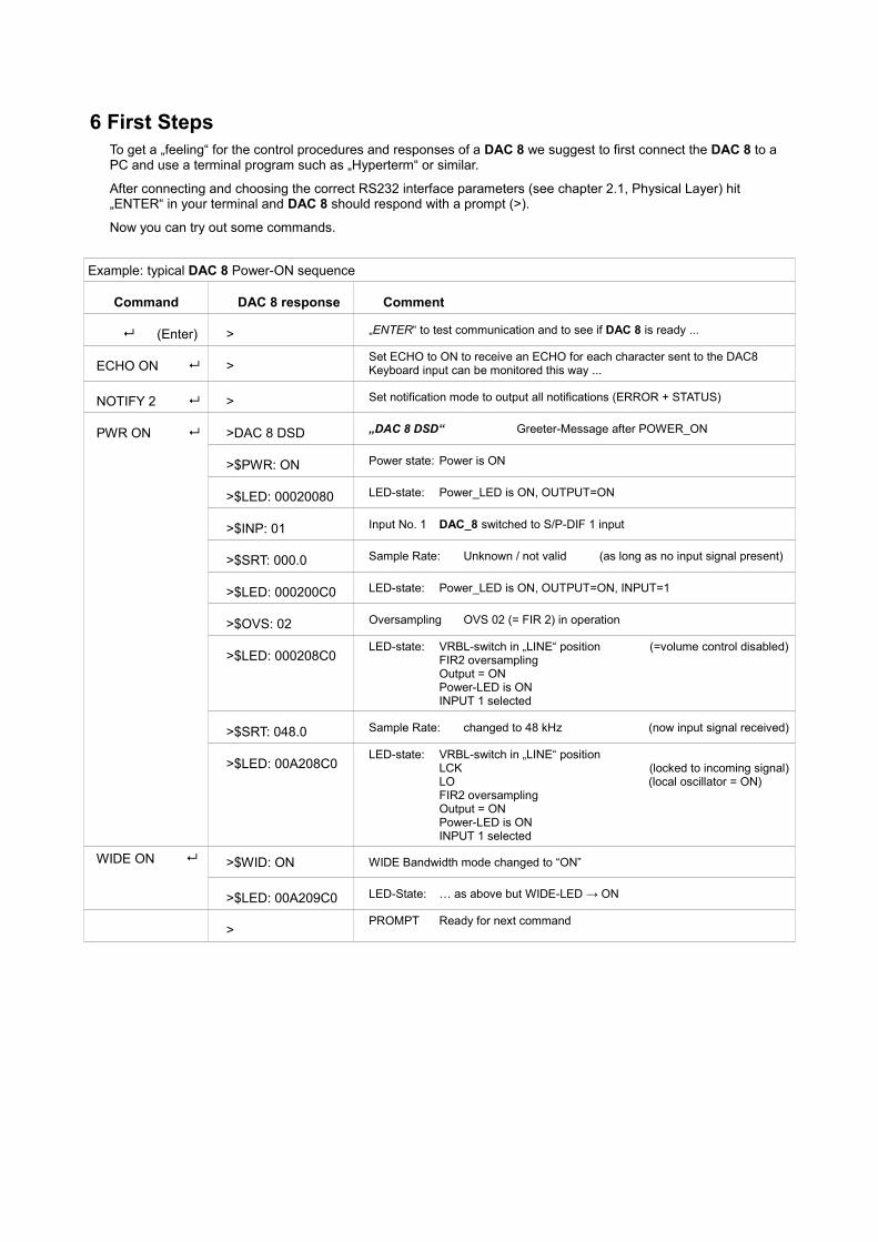
6 First StepsTo get a „feeling“ for the control procedures and responses of a DAC 8 we suggest to first connect the DAC 8 to a PC and use a terminal program such as „Hyperterm“ or similar.
After connecting and choosing the correct RS232 interface parameters (see chapter 2.1, Physical Layer) hit „ENTER“ in your terminal and DAC 8 should respond with a prompt (>).
Now you can try out some commands.
Example: typical DAC 8 Power-ON sequence
Command DAC 8 response Comment
(Enter) > „ENTER“ to test communication and to see if DAC 8 is ready ...
ECHO ON >Set ECHO to ON to receive an ECHO for each character sent to the DAC8 Keyboard input can be monitored this way ...
NOTIFY 2 > Set notification mode to output all notifications (ERROR + STATUS)
PWR ON >DAC 8 DSD „DAC 8 DSD“ Greeter-Message after POWER_ON
>$PWR: ON Power state: Power is ON
>$LED: 00020080 LED-state: Power_LED is ON, OUTPUT=ON
>$INP: 01 Input No. 1 DAC_8 switched to S/P-DIF 1 input
>$SRT: 000.0 Sample Rate: Unknown / not valid (as long as no input signal present)
>$LED: 000200C0 LED-state: Power_LED is ON, OUTPUT=ON, INPUT=1
>$OVS: 02 Oversampling OVS 02 (= FIR 2) in operation
>$LED: 000208C0LED-state: VRBL-switch in „LINE“ position (=volume control disabled)
FIR2 oversamplingOutput = ONPower-LED is ONINPUT 1 selected
>$SRT: 048.0 Sample Rate: changed to 48 kHz (now input signal received)
>$LED: 00A208C0LED-state: VRBL-switch in „LINE“ position
LCK (locked to incoming signal)LO (local oscillator = ON)FIR2 oversamplingOutput = ONPower-LED is ONINPUT 1 selected
WIDE ON >$WID: ON WIDE Bandwidth mode changed to “ON”
>$LED: 00A209C0 LED-State: … as above but WIDE-LED → ON
>PROMPT Ready for next command