DA PAM 738_751 Functional users Manual for the Army Maintenance magement System
277
Department of the Army Pamphlet 738–751 Logistics Management Functional Users Manual for the Army Maintenance Management System— Aviation (TAMMS-A) Headquarters Department of the Army Washington, DC 15 March 1999 UNCLASSIFIED
-
Upload
pauleus2002 -
Category
Documents
-
view
1.170 -
download
16
Transcript of DA PAM 738_751 Functional users Manual for the Army Maintenance magement System
Department of the ArmyPamphlet 738–751
Logistics Management
FunctionalUsers Manualfor the ArmyMaintenanceManagementSystem—Aviation(TAMMS-A)
HeadquartersDepartment of the ArmyWashington, DC15 March 1999
UNCLASSIFIED

SUMMARY of CHANGEDA PAM 738–751Functional Users Manual for the Army Maintenance Management System—Aviation (TAMMS-A)
This revision--
o Adds an Aircraft Transfer Decision Table (chap 1).
o Converts the removal/achievement codes back to failure codes (chap 1).
o Adds procedures for the Unit Level Logistics System-Aviation (chaps 1, 2, 3,and 4).
o Introduces DA Form 2408-14-1 (Uncorrected Fault Record Aircraft) (chap 2). DAForm 2408-14 (Uncorrected Fault Record) will no longer be used for aviationequipment.
o Incorporates Standard Army Maintenance System procedures (chap 3).
o Adds procedures for documentation of component repair at AviationIntermediate Maintenance and depot levels of maintenance (chap 3).
o Adds phase maintenance and periodic inspection documentation procedures(chap 3).
o Adds information on migrating automated DA Form 2410 (Component Removal andRepair/Overhaul Record) data (chap 3).
o Changes DA Form 2410 and instructions. Therefore, the U.S. Army Aviation andMissile Command’s Guide/Workbook for the DA Form 2410, The Army MaintenanceManagement System Aviation (TAMMS-A), October 1992, is obsolete (chap 3).
o Adds instructions for DA Form 2408-16 (Aircraft Component Historical Record)and DA Form 2410 to track aircraft survivability equipment electroniccountermeasures and avionics systems Line Replaceable Units that havesoftware installed (chaps 3 and 4).
o Incorporates the forms and records instructions published in TB 1-2840-248-20-2 (One Time Inspection and Conversion of Forms and Records for T700, 701,and 701C Series Gas Turbine Engines) (chaps 3 and 4).
o Incorporates the forms and records instructions published in TB 1-2840-214-20-1 (One Time Inspection of Forms and Records for H-60 Series AircraftAuxiliary Power Units) (chaps 3 and 4).
o Adds DA Form 2408-33-R (Meter Tracked Component Record) and instructions fortracking countermeasure set, AN/ALQ-144A (chap 4).
o Incorporates the forms and records instructions published in TB 55-1520-238-23 (AH-64A Components Requiring Maintenance Management and Historical Data)(chap 4).

o Adds Aviation Life Support Equipment and Aviation Night Vision Gogglerecordkeeping procedures (chap 5).
o Changes DA Form 2408-25 (Mesh Net Survival Vest Inspection Record) to includefirst aid components (chap 5).
o Discontinues use of DA Form 2409 (Equipment Maintenance Log Consolidated) foraircraft and aviation associated equipment use.
o Rescinds DA Form 2408-15-1 (Warranty Identification Card).
o Rescinds DA Form 2408-5-2 (Equipment Modification Record).
o Rescinds DA Form 2408-32, (Jet Fuel Conversion Chart).
o Rescinds DA Form 5504 and 5504-1, (Maintenance Request and Continuation Sheet(SAMS)).

HeadquartersDepartment of the ArmyWashington, DC15 March 1999
Logistics Management
Functional Users Manual for the Army Maintenance Management System—Aviation (TAMMS-A)
*Department of the ArmyPamphlet 738–751
History. This is a revision of this publication.Graphics that were incomplete in the printedc o p y h a v e b e e n c o r r e c t e d i n t h i s e l e c t r o n i cedition.Summary. This pamphlet covers the prepa-ration and management of forms and recordsneeded to manage maintenance, control theuse, and report warranty actions and deficien-cies on Army aircraft and aviation associatedequipment.Applicability.
a. This pamphlet applies to the Active Ar-my, US Army National Guard of the UnitedS t a t e s ( A R N G U S ) , U S A r m y R e s e r v e(USAR), Department of Defense (DOD), andother Government agencies that operate andmaintain Army aircraft.
b. This pamphlet also applies to all aircraftand aviation associated equipment operated,maintained, and stored by DOD contract sup-port maintenance activities.
c. During mobilization, chapters and poli-c i e s c o n t a i n e d i n t h i s p a m p h l e t m a y b emodified by the proponent.P r o p o n e n t a n d e x c e p t i o n a u t h o r i t y .The proponent of this pamphlet is the DeputyChief of Staff for Logistics. The proponenthas the authority to approve exceptions tothis pamphlet that are consistent with control-l i n g l a w a n d r e g u l a t i o n s . P r o p o n e n t s m a ydelegate the approval authority, in writing, toa division chief within the proponent agencyin the grade of colonel or the civilian equiva-lent.Suggested Improvements. Users are in-vited to send comments and suggested im-p r o v e m e n t s o n D A F o r m 2 0 2 8(Recommended Changes to Publications andBlank Forms) directly to Commander, U.S.A r m y A v i a t i o n a n d M i s s i l e C o m m a n d ,A T T N : A M S A M - M M C - R E - F F , R e d s t o n eA r s e n a l , H u n t s v i l l e , A L 3 5 8 9 8 - 5 2 3 0 . Y o umay also submit your recommended changesb y e - m a i l d i r e c t l y t o ( w a l d e c k - a b @ e x c h a -nge1.redstone.army.mil). The following for-mat must be used if submitting an electronic2028. The subject line must be exactly thesame and all fields must be included; howev-er, only the following fields are mandatory:1, 3, 4, 5, 6, 7, 8, 9, 10, 13, 15, 16, 17, and27.From: "Whomever" ([email protected]).T o : w a l d e c k - a b @ e x c h a n g e 1 . r e d s t o n e . a r m y .milSubject: DA Form 20281. From: Joe Smith2. Unit: home3. Address: 4300 Park
4. City: Hometown5. St: MO6. Zip: 77777-77777. Date Sent: 19-OCT-948. Pub No: 738-7519. Pub Title: DA Pam10. Pub Date: 15-JUN-9211. Change Number: 712. Submitter Rank: MSG13. Submitter FName: Joe14. Submitter MName: T15. Submitter LName: Smith16. Submitter Phone: 123-123-123417. Problem: 118. Page: 219. Paragraph: 320. Line: 421. NSN: 522. Reference: 623. Figure: 724. Table: 825. Item: 926. Total: 12327. Text:This is the text for the problem below line27.
Distribution. Distribution of this publica-tion is made in accordance with initial distri-bution number (IDN) 092374, intended forcommand levels A, B, C, D, and E for ActiveA r m y , t h e A r m y N a t i o n a l G u a r d o f t h eUnited States, U.S. Army Reserve, and otherGovernment Agencies.
Contents (Listed by paragraph and page number)
Chapter 1Introduction, page 1Purpose • 1–1, page 1References • 1–2, page 1Explanation of abbreviations and terms • 1–3, page 1Types of records • 1–4, page 1Tables and appendixes • 1–5, page 1General instructions • 1–6, page 1Responsibilities of forms • 1–7, page 3How to use status symbols • 1–8, page 4
Clearing status symbols • 1–9, page 5Evacuation of aircraft on a Red “X” status symbol • 1–10, page 6Maintenance test flight verification of aircraft on a Red “X” status
symbol • 1–11, page 6Safety-Of-Flight Messages, Aviation Safety Action Messages,
Technical Bulletins, and Maintenance Informational Messages(MIMs) • 1–12, page 6
Safety-Of-Use Messages, Urgent MWOs, and TBs • 1–13, page 7Missing historical records or information • 1–14, page 7Aircraft and aviation associated equipment files content and
management • 1–15, page 8Records to accompany aircraft • 1–16, page 9
*This pamphlet supersedes DA Pam 738-751, 15 June 1992; TB 55-1520-238-23, 4 June 1984; TB 1-2840-248-20-2, 30 June 1994; TB 1-2835-214-20-1, 30 June 1994,and TB 1-1500-348-20, 18 November 1994.
DA PAM 738–751 • 15 March 1999 i
UNCLASSIFIED

Contents—Continued
Excess, Deteriorated, Crash Damaged, or Destroyed U.S. ArmyAircraft Transferred to Defense Reutilization and MarketingOffice • 1–17, page 9
Aircraft transferred to other Government agencies and the MilitaryAssistance Program • 1–18, page 10
Aircraft used for static display or transferred to museums • 1–19,page 11
Aircraft and components used for maintenance training • 1–20,page 11
U.S. Army aircraft loaned or bailed, or procured for other U.S.Government departments and agencies • 1–21, page 11
Classifying records and reports • 1–22, page 12Unit Level Logistics System-Aviation and Logbook Automated
System • 1–23, page 12Aircraft Quality Control Program • 1–24, page 13Aircraft weight and balance Control • 1–25, page 13Aviation night vision goggles maintenance • 1–26, page 13Standard Army Maintenance System • 1–27, page 13Aircraft component/module repair • 1–28, page 14
Chapter 2Aircraft Logbook Forms and Records, page 25General-aircraft logbook forms and records • 2–1, page 25Logbook Binder (NSN 7510–00–889–3494 (2 1/2 inch)) • 2–2,
page 25DA Form 2408, Equipment Log Assembly • 2–3, page 25DA Form 2408–31, Aircraft Identification Card • 2–4, page 25DA Form 2408–4–1, Weapon Record Data • 2–5, page 25DA Form 2408–4–2, Weapon Sighting Data (OH-58D) • 2–6,
page 26DA Form 2408–4–3, Weapon Sighting Data (AH-64A) • 2–7,
page 26DA Form 2408–12, Army Aviator’s Flight Record • 2–8, page 26DA Form 2408–13, Aircraft Status Information Record • 2–9,
page 27DA Form 2408–13–1, Aircraft Inspection and Maintenance Record
• 2–10, page 28DA Forms 2408–13–2, Related Maintenance Actions Record
• 2–11, page 30DA Form 2408–14–1, Uncorrected Fault Record (Aircraft) • 2–12,
page 31DA Form 2408–18, Equipment Inspection List • 2–13, page 31
Chapter 3Maintenance Forms and Records, page 61General maintenance forms • 3–1, page 61Product quality deficiency reports • 3–2, page 61PQDR exhibits • 3–3, page 64Reporting initial failure of a stock-funded depot level reparable
item • 3–4, page 66DA Form 2402, Exchange tag. • 3–5, page 66DD Form 2332, Product Quality Deficiency Report Exhibit. • 3–6,
page 66DD Form 173/3, Joint Message Form (Category I Deficiency
Report). • 3–7, page 66SF Form 368, Product Quality Deficiency Report. • 3–8, page 66DA Form 2408–13–3, Aircraft Technical Inspection Worksheet.
• 3–9, page 67DA Form 2405, Maintenance Request Register. • 3–10, page 69DA Form 2407, Maintenance Request, and DA Form 2407–1,
Maintenance Request Continuation Sheet. • 3–11, page 69Maintenance inspection checklist. • 3–12, page 71DA Form 2410, Component Removal and Repair/Overhaul Record
(RCS CSGLD-1052 (R3)). • 3–13, page 72DA Form 2410, Gains to Inventory. • 3–14, page 73DA Form 2410, Normal Removal, Repair, Overhaul/Rebuild and
Installation. • 3–15, page 73
DA Form 2410, Changes from Serviceable to Unserviceable Statusfor Uninstalled Items. • 3–16, page 74
DA Form 2410, NSN/PN/Serial Number (SN) Changes. • 3–17,page 74
DA Form 2410, Removal of Serviceable Reportable Items forControlled Exchange. • 3–18, page 74
DA Form 2410, Loss to Inventory. • 3–19, page 74Materiel Condition Tags/Labels on Uninstalled Aviation Equipment
and Aviation Associated Equipment. • 3–20, page 74Supply condition codes. • 3–21, page 75DD Form 1574, Serviceable Tag-Materiel, and DD Form 1574-1,
Serviceable Label-Materiel, (Yellow). • 3–22, page 75DD Form 1575, Suspended Tag-Materiel, and DD Form 1575-1,
Suspended Label-Materiel, (Brown). • 3–23, page 75DD Form 1576, Test/Modification Tag-Materiel, and DD Form
1576-1, Test/Modification Label-Materiel, (Blue). • 3–24,page 75
DD Form 1577, Unserviceable (Condemned) Tag-Materiel, and DDForm 1577-1, Unserviceable (Condemned) Label-Materiel, (Red).• 3–25, page 75
DD Form 1577-2, Unserviceable (Reparable) Tag-Materiel, and DDForm 1577-3 Unserviceable (Reparable) Label-Material, (Green).• 3–26, page 75
Chapter 4Historical Forms and Records, page 159General-historical forms • 4–1, page 159Missing historical records or information. • 4–2, page 159DA Form 2408–5, Equipment Modification Record. • 4–3,
page 159DA Form 2408–5–1, Equipment Modification Record (Component)
. • 4–4, page 160DA Form 2408–15, Historical Record for Aircraft. • 4–5,
page 160DA Form 2408–15–2, Aircraft Vibration Record. • 4–6, page 161DA Form 2408–16, Aircraft Component Historical Record. • 4–7,
page 161DA Form 2408–16–1, History Recorder, Component, Module
Record. • 4–8, page 162DA Form 2408–17, Aircraft Inventory Record. • 4–9, page 163DA Form 2408–19, Aircraft Engine Turbine Wheel Historical
Record. • 4–10, page 164DA Form 2408–19–1, T53/T55 Turbine Engine Analysis Check
Record. • 4–11, page 164DA Form 2408–19–2, T700 Series Turbine Engine Analysis Check
Record. • 4–12, page 164DA Form 2408–19–3, Engine Component Operating Hours Record.
• 4–13, page 165DA Form 2408–20, Oil Analysis Log. • 4–14, page 165DA Form 2408–33–R, Meter Tracked Component Record • 4–15,
page 165
Chapter 5Aviation Life Support Equipment and Aviation Night Vision
Goggles Forms and Records Procedures, page 218General • 5–1, page 218DA Form 2407, Maintenance Request, and DA Form 2407–1,
Maintenance Request Continuation Sheet • 5–2, page 218DA Form 2408–5, Equipment Modification Record. • 5–3,
page 218DA Form 2408–15, Historical Record for Aircraft • 5–4, page 219DA Form 2408–21, Life Raft Inspection Record. • 5–5, page 219DA Form 2408–22, Helmet and Oxygen Mask/Connector
Inspection Record. • 5–6, page 219DA Form 2408–23, Survival Radio/Emergency Location
Transmitter Inspection Record. • 5–7, page 219DA Form 2408–24, Survival Kit Inspection and Maintenance
Record. • 5–8, page 219
ii DA PAM 738–751 • 15 March 1999
Contents—Continued
DA Form 2408–25, Mesh Net Survival Vest Inspection Record. • 5–9, page 220
DA Form 2408–26, Life Preserver Inspection Record. • 5–10,page 220
DA Form 2408–27, Life Preserver Data. • 5–11, page 220DA Form 2408–28, Oxygen Console Service Record. • 5–12,
page 220DA Form 2408–29, Anti-Exposure Coveralls Inspection Record.
• 5–13, page 220DA Form 2408–30, NVG Inspection and Maintenance Record.
• 5–14, page 220DD Forms 1574/1574–1, 1575/1575–1, 1576/1576–1, 1577/1577–1,
and 1577–2/1577–3, Tags/Labels (Material). • 5–15, page 221
Appendixes
A. References, page 246
B. Nuclear, Biological, and Chemical Detection-DecontaminationDocumentation Procedures, page 248
C. Supply Condition Codes, page 249
D. Department of the Army list of Aircraft and AviationAssociated Equipment on which forms and records are tobe maintained, page 250
E. List of Aircraft and their National Stock Numbers, page 254
Table List
Table 1–1: Red "X" Conditions for Aviation Equipment, page 14Table 1–2: Failure Codes--Alphabetical, page 15Table 1–3: Failure Codes&emdash;Numerical, page 18Table 1–4: When Discovered Codes, page 20Table 1–5: How Recognized Codes, page 20Table 1–6: Malfunction Effect Codes, page 20Table 1–7: System Codes, page 20Table 1–8: DA Form 2408-18 Frequency Codes, page 20Table 1–9: Maintenance Action Codes, page 20Table 1–10: Functional Group Codes, page 21Table 1–11: Utilization Codes, page 21Table 1–12: Time Conversion Codes, page 22Table 1–13: Equipment Loss Codes, page 22Table 1–14: Equipment Gain Codes, page 22Table 1–15: Not Reparable This Station Codes (NRTS), page 23Table 1–16: Type Maintenance Request Code (Type MNT Req
CD) or Repair, page 23Table 1–17: Work Request Status Codes (STA), page 23Table 1–18: Part Source Code, page 24Table 1–19: The Metric System and Equivalents, page 24Table 1–20: Aircraft Transfer Decision Table, page 24Table 3–1: SSCOM (TROOP) QDR Action Point Address,
page 63Table 3–2: TACOM-ARDEC QDR Action Point Address, page 63Table 3–3: CECOM QDR Action Point Address, page 63Table 3–4: AMCOM QDR Action Point Address, page 63Table 3–5: TACOM QDR Action Point Address, page 64Table 3–6: IOC QDR Action Point Address, page 64Table 3–7: Logistic Assistance Offices and Logistic Assistance
Representatives1, page 76Table 3–8: Sample of a Maintenance Records Checklist, page 78Table 3–9: AMCOM Modification Work Order Contract Field
Team Application Facility Addresses and Geographical SupportAreas, page 79
Table B–1: Legend: Nuclear, Biological, and Chemical Detection-Decontamination Documentation Procedures, page 249
Table C–1: Supply Condition Codes, page 249Table D–1: DA FORMS TO BE MAINTAINED (page 1),
page 251
Table D–1: DA FORMS TO BE MAINTAINED (page 2),page 252
Table D–1: DA FORMS TO BE MAINTAINED (page 3),page 253
Table D–1: DA FORMS TO BE MAINTAINED (page 4),page 254
Table D–1: DA FORMS TO BE MAINTAINED (page 5),page 254
Table E–1: List of Aircraft and their National Stock Numbers,page 254
Figure List
Figure 2–1: Sample Logbook Binder, page 33Figure 2–2A: Sample of an Equipment Log Assembly (DA Form
2408) (Illustration #1, Front), page 34Figure 2–2B: Sample of a Equipment Log Assembly (DA Form
2408) (Illustration #2, Reverse), page 35Figure 2–3: Sample of a completed DA Form 2408–31 (Aircraft
Identification Card), page 36Figure 2–4: Sample of a completed DA Form 2408–4–1 (Weapon
Record Data), page 37Figure 2–5: Sample of a completed DA Form 2408–4–2 (Weapon
Sighting Data OH-58D), page 38Figure 2–6: Sample of a completed DA Form 2408–4–3 (Weapon
Sighting Data AH-64A), page 39Figure 2–7A: Sample of a completed DA Form 2408–12 (Army
Aviators Flight Record) (Illustration #1), page 41Figure 2–7B: Sample of a completed DA Form 2408–12 (Army
Aviators Flight Record) (Illustration #2), page 43Figure 2–8A: Sample of a completed DA Form 2408–13 (Aircraft
Status Information Record) (Illustration #1), page 45Figure 2–8B: Sample of a completed DA Form 2408–13 (Aircraft
Status Information Record) (Illustration #2), page 46Figure 2–9A: Sample of a completed DA Form 2408–13–1
(Aircraft Inspection and Maintenance Record) (Illustration #1),page 49
Figure 2–9B: Sample of a Completed DA Form 2408–13–1(Aircraft Inspection and Maintenance Record) (Illustration #2),page 50
Figure 2–9C: Sample of a completed DA Form 2408–13–1(Aircraft Inspection and Maintenance Record) (Illustration #3),page 51
Figure 2–10A: Sample of a completed DA Form 2408–13–2(Related Maintenance Actions Record) (Illustration #1, Front),page 55
Figure 2–10B: Sample of a completed DA Form 2408–13–2(Related Maintenance Actions Record) (Illustration #2, Reverse),page 56
Figure 2–11: Sample of a completed DA Form 2408–13–2 (RelatedMaintenance Action Record) (Component Repair), page 57
Figure 2–12: Sample of a completed DA Form 2408–14–1(Uncorrected Fault Record) (Aircraft), page 59
Figure 2–13: Sample of a completed DA Form 2408–18(Equipment Inspection List), page 60
Figure 3–1: Sample of a DA Form 2402 Exchange Tag, page 80Figure 3–2: Sample of a completed DD Form 2332 (Product
Quality Deficiency Report Exhibit), page 82Figure 3–3A: Sample of a completed Category I Deficiency Report
(message format), page 84Figure 3–3B: Sample of a completed Category I Deficiency Report
(message format), page 85Figure 3–3C: Sample of a completed Category I Deficiency Report
(message format), page 86Figure 3–3D: Sample of a completed Category I Deficiency Report
(message format), page 87Figure 3–4A: Sample of a completed SF 368 for a Category II
Deficiency Report, page 91
iiiDA PAM 738–751 • 15 March 1999
Contents—Continued
Figure 3–4B: Sample of a completed SF 368 for a Category IIDeficiency Report, page 92
Figure 3–5: Sample of a completed DA Form 2408-13-3 (AircraftTechnical Inspection Worksheet) (Technical Inspection), page 95
Figure 3–6: Sample of a completed DA Form 2408-13-3 (AircraftTechnical Inspection Worksheet) (Component Repair), page 96
Figure 3–7: Sample of a completed DA Form 2405, MaintenanceRequest Register, page 99
Figure 3–8: Sample of a completed DA Form 2407 to requestsupport maintenance., page 100
Figure 3–9: Sample of a completed DA Form 2407 to show workdone at support maintenance, page 103
Figure 3–10: Sample of a completed DA Form 2407 to requestapplication of an MWO, page 107
Figure 3–11: Sample of a completed DA Form 2407 to report anMWO done at Support Maintenance, page 110
Figure 3–12: Sample of a completed page of a phase maintenancechecklist., page 113
Figure 3–13: Sample of a completed DA Form 2408-13-2 used todocument disassembly to complete an inspection requirementduring phase maintenance, page 115
Figure 3–14A: Sample of a completed DA Form 2410 for gain tothe Army inventory. (Illustration #1), page 117
Figure 3–14B: Sample of a completed DA Form 2410 for gain tothe Army inventory. (Illustration #2), page 118
Figure 3–15: Sample of a completed DA Form 2410 for thenormal removal, evacuation, repair, and installation cycle.(Removal and Evacuation), page 120
Figure 3–16: Sample of a completed DA Form 2410 for normalremoval, evacuation, repair, and installation cycle (Repair/Overhaul), page 123
Figure 3–17: Sample of a completed DA Form 2410. Reverse ofcopy #2., page 125
Figure 3–18: Sample of a completed DA Form 2410 for theNormal Evacuation Repair and Installation Cycle, (Installation),page 126
Figure 3–19: Sample of a completed DA Form 2410 for changefrom serviceable to unserviceable uninstalled items. (Installation),page 128
Figure 3–20A: Sample of a completed DA Form 2410 for an NSN/PN/serial number change for an uninstalled item. (Illustration #1), page 129
Figure 3–20B: Sample of a completed DA Form 2410 for an NSN/PN/serial number change of an uninstalled item. (Illustration #2),page 130
Figure 3–21A: Sample of a completed DA Form 2410 for a NSN/PN/serial number change for an installed item. (Illustration #1),page 132
Figure 3–21B: Sample of a completed DA Form 2410 for a NSN/PN/serial number change for an installed item. (Illustration #2),page 133
Figure 3–21C: Sample of a completed DA Form 2410 for an NSN/PN/serial number change for an installed item. (Illustration #3),page 134
Figure 3–21D: Sample of a completed DA Form 2410 for a NSN/PN/serial number change for an installed item. (Illustration #4),page 135
Figure 3–22: Sample of a completed DA Form 2410 when aserviceable reportable item is removed for controlled exchange.(Identification and Removal Data), page 139
Figure 3–23: Sample of a completed DA Form 2410 when aserviceable reportable item is removed for controlled exchange.(Installation Data), page 141
Figure 3–24A: Sample of a completed DA Form 2410 for loss tothe Army inventory when a loss code of "D" or "J" is used.(Illustration #1), page 143
Figure 3–24B: Sample of a completed DA Form 2410 for loss tothe Army inventory when a loss code of "D" or "J" is used.(Illustration #2), page 144
Figure 3–25A: Sample of a completed DA Form 2410 for loss tothe Army inventory when a loss code other than "D", "J", or"M" is used. (Illustration #1)., page 147
Figure 3–25B: Sample of a completed DA Form 2410 for loss tothe Army inventory when a loss code other than "D", "J", or"M" is used. (Illustration #2)., page 148
Figure 3–26: Sample of a completed DD Form 1574 and DD Form1574-1, Serviceable Tag/Label-Materiel (Color Yellow),page 151
Figure 3–27: Sample of a completed DD Form 1575 and DD Form1575-1, Suspended Tag/Label-Materiel (Color Brown), page 152
Figure 3–28A: Sample of a completed DD Form 1576 and DDForm 1576-1, Test/Modification Tag/Label-Materiel (Color Blue); Illustration #1, page 154
Figure 3–28B: Sample of a completed DD Form 1576 and DDForm 1576-1, Test/Modification Tag/Label-Materiel (Color Blue); Illustration #2, page 155
Figure 3–29: Sample of a completed DD Form 1577 and DD Form1577-1, Unserviceable (Condemned) Tag/Label-Materiel (ColorRed), page 156
Figure 3–30: Sample of a completed DD Form 1577-2 and DDForm 1577-3, Unserviceable (Reparable) Tag/Label-Materiel(Color Green), page 158
Figure 4–1: Sample of a completed DA Form 2408–5, EquipmentModification Record, page 166
Figure 4–2: Sample of a completed DA Form 2408–5–1,Equipment Modification Record (Component), page 168
Figure 4–3: Sample of a completed DA Form 2408–15, HistoricalRecord For Aircraft, page 169
Figure 4–4: Sample of a completed DA Form 2408–15–2, AircraftVibration Record, page 170
Figure 4–5A: Sample of a completed DA Form 2408–16, AircraftComponent Historical Record (To record historical data onselected aircraft components, modules) (Time ChangeComponents) (Illustration #1), page 171
Figure 4–5B: Sample of a completed DA Form 2408–16, AircraftComponent Historical Record (To record historical data onselected aircraft components, modules) (Time ChangeComponents) (Illustration #2), page 172
Figure 4–5C: Sample of a completed DA Form 2408–16, AircraftComponent Historical Record (To record historical data onselected aircraft components, modules) (Condition Items)(Illustration #3), page 173
Figure 4–5D: Sample of a completed DA Form 2408–16, AircraftComponent Historical Record (To record historical data onselected aircraft components, modules) (Major Component Form)(Illustration #4), page 174
Figure 4–5E: Sample of a completed DA Form 2408–16, AircraftComponent Historical Record (To record historical data onselected aircraft components, modules) (Major Component Form)(Illustration #5), page 175
Figure 4–6A: Sample of a completed DA Form 2408–16–1,History Recorder Component Module Record. T700 series engineshowing major modules and components. (Illustration #1),page 178
Figure 4–6B: Sample of a completed DA Form 2408–16–1,History Recorder Component Module Record. T700 series engineshowing major modules and components. (Illustration #2),page 179
Figure 4–6C: Sample of a completed DA Form 2408–16–1,History Recorder Component Module Record. T700 series engineshowing major modules and components. (Illustration #3),page 180
iv DA PAM 738–751 • 15 March 1999

Contents—Continued
Figure 4–7A: Sample of a completed DA Form 2408–16–1,History Recorder Component Module Record. New T700 seriesengines, components or modules for spares. (Illustration #1),page 182
Figure 4–7B: Sample of a completed DA Form 2408–16–1,History Recorder Component Module Record. New T700 seriesengines, components or modules for spares. (Illustration #2),page 183
Figure 4–8A: Sample of a completed DA Form 2408–16–1,History Recorder Component Module Record. Removal of amodule from a T700 series engine. (Illustration #1), page 185
Figure 4–8B: Sample of a completed DA Form 2408–16–1,History Recorder Component Module Record. Installation of amodule on a T700 series engine. (Illustration #2), page 186
Figure 4–8C: Sample of a completed DA Form 2408–16–1,History Recorder Component Module Record. Installation of amodule on a T700 series engine. (Illustration #3), page 187
Figure 4–9A: Sample of a completed DA Form 2408–16–1,History Recorder Component Module Record. Depot repair of aT700 series engine module. (Illustration #1, Front), page 189
Figure 4–9B: Sample of a completed DA Form 2408–16–1,History Recorder Component Module Record. Depot repair of aT700 series engine module. (Illustration #2, Reverse), page 190
Figure 4–10A: Sample of a completed DA Form 2408–16–1,History Recorder Component Module Record. Replacement of aT700 series engine history recorder. (Illustration #1), page 192
Figure 4–10B: Sample of a completed DA Form 2408–16–1,History Recorder Component Module Record. Replacement of aT700 series engine history recorder. (Illustration #2), page 193
Figure 4–11A: Sample of a completed DA Form 2408–16–1,History Recorder Component Module Record. Depot repair oroverhaul of a H-60 series aircraft APU. (Illustration #1, Front),page 194
Figure 4–11B: Sample of a completed DA Form 2408–16–1,History Recorder Component Module Record. Depot repair oroverhaul of a H-60 series aircraft APU. (Illustration #2, Reverse), page 195
Figure 4–12A: Sample of a completed DA Form 2408–16–1,History Recorder Component Module Record. Field replacement(Installation) of a H-60 series aircraft APU) (Illustration #1),page 197
Figure 4–12B: Sample of a completed DA Form 2408–16–1,History Recorder Component Module Record. Field replacement(Removal) of a H-60 series aircraft APU) (Illustration #2),page 198
Figure 4–12C: Sample of a completed DA Form 2408–16–1,History Recorder Component Module Record. Field replacement(Controlled Substitution) of a H-60 series aircraft APU)(Illustration #3), page 199
Figure 4–13: Sample of a completed DA Form 2408–16–1, HistoryRecorder Component Module Record. Replacement of ahourmeter on a H-60 series aircraft APU., page 201
Figure 4–14A: Sample of a completed DA Form 2408–17. AircraftInventory Record. (Illustration #2, Front), page 203
Figure 4–14B: Sample of a completed DA Form 2408–17. AircraftInventory Record. (Illustration #2, Reverse), page 204
Figure 4–15A: Sample of a completed DA Form 2408–19. AircraftEngine Turbine Wheel Historical Record (Illustration #1, Front),page 205
Figure 4–15B: Sample of a completed DA Form 2408–19. AircraftEngine Turbine Wheel Historical Record (Illustration #2,Reverse), page 206
Figure 4–16A: Sample of a completed DA Form 2408–19–1. T53/T55 Turbine Engine Analysis Check Record (Illustration #1),page 208
Figure 4–16B: Sample of a completed DA Form 2408–19–1. T53/T55 Turbine Engine Analysis Check Record (Illustration #2),page 209
Figure 4–17: Sample of a completed DA Form 2408–19–2. T700Series Turbine Engine Analysis Check Record (Illustration #2),page 210
Figure 4–18: Sample of a completed DA Form 2408–19–3. EngineComponent Operating Hours Record, page 212
Figure 4–19A: Sample of a completed DA Form 2408–20. OilAnalysis Log (Illustration #1, Front), page 213
Figure 4–19B: Sample of a completed DA Form 2408–20. OilAnalysis Log (Illustration #2, Reverse), page 214
Figure 4–20A: Sample of a completed DA Form 2408–33–R.Meter Tracked Component Record (Illustration #1, Front),page 216
Figure 4–20B: Sample of a completed DA Form 2408–33–R.Meter Tracked Component Record (Illustration #2, Reverse),page 217
Figure 5–1: Sample of a completed DA Form 2408–5, EquipmentModification Record., page 222
Figure 5–2: Sample of a completed DA Form 2408–15, HistoricalRecord for Aircraft, page 223
Figure 5–3A: Sample of a completed DA Form 2408–21, Life RaftInspection Record (Illustration #1, Front), page 224
Figure 5–3B: Sample of a completed DA Form 2408–21, Life RaftInspection Record (Illustration #2, Reverse), page 225
Figure 5–4: Sample of a completed DA Form 2408–22, Helmetand Oxygen Mask/Connector Inspection Record, page 227
Figure 5–5: Sample of a completed DA Form 2408–23, SurvivalRadio/Emergency Locator Transmitter Inspection Record,page 228
Figure 5–6A: Sample of a completed DA Form 2408–24, SurvivalKit Inspection and Maintenance Record (Illustration #1, Front),page 229
Figure 5–6B: Sample of a completed DA Form 2408–24, SurvivalKit Inspection and Maintenance Record (Illustration #2, Reverse), page 230
Figure 5–7A: Sample of a completed DA Form 2408–25, MeshNet Survival Vest Inspection Record (Illustration #1, Front),page 231
Figure 5–7B: Sample of a completed DA Form 2408–25, MeshNet Survival Vest Inspection Record (Illustration #2, Reverse),page 232
Figure 5–8A: Sample of a completed DA Form 2408–26, LifePreserver Inspection Record (Illustration #1, Front), page 233
Figure 5–8B: Sample of a completed DA Form 2408–26, LifePreserver Inspection Record (Illustration #2, Reverse), page 234
Figure 5–9A: Sample of a completed DA Form 2408–27, LifePreserver Data (Illustration #1, Front), page 236
Figure 5–9B: Sample of a completed DA Form 2408–27, LifePreserver Data (Illustration #2, Reverse), page 237
Figure 5–10A: Sample of a completed DA Form 2408–28, OxygenConsole Service Record (Illustration #1, Front), page 238
Figure 5–10B: Sample of a completed DA Form 2408–28, OxygenConsole Service Record (Illustration #2, Reverse), page 239
Figure 5–11A: Sample of a completed DA Form 2408–29, Anti-Exposure Coveralls Inspection Record (Illustration #1, Front),page 240
Figure 5–11B: Sample of a completed DA Form 2408–29, Anti-Exposure Coveralls Inspection Record (Illustration #2, Reverse),page 241
Figure 5–12A: Sample of a completed DA Form 2408–30, NVGInspection and Maintenance Record (Illustration #1, Front),page 242
Figure 5–12B: Sample of a completed DA Form 2408–30, NVGInspection and Maintenance Record (Illustration #2, Reverse),page 243
vDA PAM 738–751 • 15 March 1999

Figure 5–12C: Sample of a completed DA Form 2408–30, NVGInspection and Maintenance Record (Illustration #3, Front),page 244
Glossary
Index
vi DA PAM 738–751 • 15 March 1999

Chapter 1Introduction
1–1. Purposea. This pamphlet provides instructions for the use, preparation,
and disposition of forms and records. The forms and records areused to control and manage aircraft, aviation-associated equipment,mission related equipment, and maintenance. AR 750–1 sets thepolicy for keeping records and AR 750–2 prescribes policy forevaluation, analysis, and use of data entered and collected on formsand records outlined in this pamphlet.
b. The forms and records are used to—(1) Control operations.(2) Control and manage maintenance of aircraft, aviation-associ-
ated equipment, and mission-related equipment.(3) Track aircraft components, modules and flight safety parts, by
serial number, to support reconstruction of aircraft component his-torical records for component configuration, and maintenance andfailure analysis.
(4) Track configuration, application of Department of the Army(DA) Modification Work Orders (MWOs), Safety-Of-Flight (SOF)messages, Aviation Safety Action Messages (ASAMs), Safety-Of-Use (SOU) messages, and Technical Bulletins (TBs) on aircraft,aviation-associated equipment, and reportable components.
(5) Collect maintenance performance and related logistic data toperform maintenance analysis for possible redesign and improve-ment of fielded aviation equipment per AR 750–2 and DA Pamphlet700–126.
(6) Submit deficiency reports, such as Equipment ImprovementRecommendations (EIRs) and Product Quality Deficiency Reports(PQDRs).
(7) Evaluate aviation materiel condition in support of aircraft andaviation-associated equipment readiness and safety.
1–2. ReferencesRequired and related publications and prescribed and referencedforms are listed in appendix A.
1–3. Explanation of abbreviations and termsAbbreviations and special terms used in this pamphlet are explainedin the glossary or the aircraft maintenance publication that applies.Other military terms are defined in AR 310–25 and abbreviationsare in AR 310–50. The terms, in quotation marks (“ ”), used ascorrecting information on aircraft forms are for illustration purposesonly. The quotation marks do not mean that the term(s) have to beused exactly as written. It is not an error to abbreviate or alter theterm(s), as long as the information is correctly described.
1–4. Types of recordsa. Aircraft logbook forms and records. Aircraft logbook forms
and records are filed in the aircraft logbook for easy access by theaircrew, maintenance, and quality control personnel. The aircraftlogbook is made up of a combination of operational and mainte-nance forms and records that provide a record of the following:
(1) Aircraft/aircrew flight information and servicing data.(2) Engine operational data.(3) Weapon(s) firing data.(4) When the next scheduled maintenance inspection is due.(5) When the next special inspection or item replacement is due.(6) Faults and correcting information.(7) Aircraft and mission-related equipment condition status.(8) Related maintenance actions.(9) Uncorrected or deferred faults or maintenance.(10) Rounds fired from weapon systems installed in each aircraft.(11) Cumulative rounds fired from all prior weapons installed on
the aircraft.(12) Identification plates for refueling of aircraft away from the
home station.b. Historical records. Historical records are permanent records of
historical data for aircraft, time change (TC), retirement change
(RC), and condition change (CC) components. Historical records arenot part of the logbook. They are normally filed in the productioncontrol or quality control (QC) shop. They keep a record of:
(1) MWOs, SOF messages, ASAMs, SOU messages, and TBs onaircraft, selected components, and other aviation equipment.
(2) All significant events on the aircraft and components.(3) Results of turbine engine analysis checks (TEACs) and/or
max power checks.(4) Receipt, transfer, and disposal of aviation equipment.(5) Software version of software installed on aircraft survivability
electronic countermeasures and avionics systems line replaceableunits (LRUs).
(6) T700 series engines operating hours, history recorder read-ings, and significant events on the engines.
c. Deficiency reports. Deficiency reports are used to suggest cor-rections and improvements to aircraft, aviation-associated equip-m e n t , m i s s i o n - r e l a t e d e q u i p m e n t , a n d m a i n t e n a n c e p r o c e d u r e scontained in maintenance technical publications. Deficiency report-ing policy and procedures are contained in chapter 3.
1–5. Tables and appendixesa. Information in tables 1–1 through 1–20, at the end of chapter
1, applies to aviation equipment, forms, and records. The tablescontain the codes used on forms and records throughout this pam-phlet. These codes and other data are extracted from forms receivedat the National Maintenance Point (NMP) and placed in computerdata bases. The data is then analyzed to identify areas having anadverse impact on the operational needs and readiness objectives ofaviation equipment. The following tables will be used for complet-ing operational, maintenance, and historical forms:
(1) Table 1–1 Red “X” Conditions for Aviation Equipment.(2) Table 1–2 Failure Codes — Alphabetical.(3) Table 1–3 Failure Codes — Numerical.(4) Table 1–4 When Discovered Codes.(5) Table 1–5 How Recognized Codes.(6) Table 1–6 Malfunction Effect Codes.(7) Table 1–7 System Codes.(8) Table 1–8 DA Form 2408–18 Frequency Codes.(9) Table 1–9 Maintenance Action Codes.(10) Table 1–10 Functional Group Codes.(11) Table 1–11 Utilization Codes.(12) Table 1–12 Time Conversion Codes.(13) Table 1–13 Equipment Loss Codes.(14) Table 1–14 Equipment Gain Codes.(15) Table 1–15 Not Reparable This Station Codes (NRTS).(16) Table 1–16 Type Maintenance Request Codes (Type MNT
Req CD).(17) Table 1–17 Work Request Status Codes (STA).(18) Table 1–18 Part Source Code.(19) Table 1–19 The Metric System and Equivalents.(20) Table 1–20 Aircraft Transfer Decision Matrix.b. Information in the appendixes applies to aviation equipment
forms and records. Appendix A lists the required and related publi-cations needed to use this pamphlet. Appendix B explains the proce-dures needed for operation in a nuclear, biological, or chemicalenvironment. Appendix C lists supply condition codes used to pre-pare other forms, records, and materiel condition tags/labels. Appen-dix D lists aircraft and aviation associated equipment with theirrequired forms and records.
1–6. General instructionsa. Specific details on how to use, fill out, process, and dispose of
aviation equipment forms and records will be found in the relatedchapters. Unless the specific instructions for the form or record stateotherwise, the following rules apply:
(1) “Not applicable,” “not required,” or “N/A” entries will be leftblank.
(2) All entries on the forms will be printed or typed exceptpersonal signatures, initials, and stamps. All logbook and mainte-nance form and record entries may be made in blue or black ball-point pen, black lead pencil, stamp, or they will be Unit Level
1DA PAM 738–751 • 15 March 1999

Logistics System-Aviation (ULLS-A) or Logbook Automated Sys-tem (LAS) generated unless the specific instructions state otherwise.Historical record entries will be made in blue or black ball-pointpen, typewritten, ULLS-A, or LAS generated unless the specificinstructions state to use pencil. The entry for total number of pages,on manually maintained forms, will be entered using black leadpencil. Use a red lead pencil or ball-point pen with red ink, to makeaircraft and aviation-associated equipment condition status symbols,except the no defect symbol (last name initial). Status symbols thatare computer generated by the ULLS-A or LAS programs are prin-ted in black ink. Typed or stamped entries must be in blue or blackink. On materiel condition tags/labels use blue or black waterproofink, because rain, snow or other moisture can smear the ink andimportant data will be lost.
(3) The minimum requirement to certify entries on all formsgoverned by this pamphlet is the Personnel Identifier (PID). ThePID is made up with the first and last name initials, plus last fournumbers of the person’s Social Security Account Number (SSAN).Commander’s (CDR(s)) designated representatives will use theirsignatures along with their PIDs. The first initial and last name, orthe complete first and last name can be used as the designatedrepresentative’s signature.
(4) A PID file will be maintained in the unit QC office or by theULLS-A or LAS administrator. The PID file for units using themanual method of recordkeeping will list the name, PID, and signa-ture of all personnel performing aircraft maintenance and the com-mander’s designated representatives. The PID file for units using theULLS-A or LAS exists within the ULLS-A and LAS program. Theinformation will remain on file a minimum of 6 months after theindividual leaves the unit.
(5) Using abbreviations and acronyms can save time and effort.Use only the abbreviations in the glossary of this pamphlet and AR3 1 0 – 5 0 . U s e o n l y a c r o n y m s i n a i r c r a f t a n d a v i a t i o n - a s s o c i a t e dequipment technical manuals (TMs).
(6) The terms noun, noun abbreviation, noun nomenclature, andname refer to the same basic identification of a repair part, compo-nent, module, or end item in this pamphlet.
(7) Aircraft serial numbers will be recorded without a hyphen ordash between the procurement fiscal year (FY) and the designatednumber. Aircraft serial numbers will contain only seven numericalcharacters. In case the serial number contains less than seven nu-merical characters, add a zero “0” or zeros following the first twocharacters (FY procurement) of the serial number. For example,serial number 84–23456 will be recorded as 8423456; 85–6789 willbe recorded as 8506789; or 90–123 will become 9000123. The entrymade on aircraft forms in this format is needed to fit the automationsystem format. Serial numbers for aircraft training devices, simula-tors, repair parts, components, modules, systems, and subsystemswill be recorded as listed on the aviation equipment data plate.
(8) Use the figures and illustrations as examples only. Read thepolicy in the text and the instructions for the specific figure. Thenfill out the forms showing your own aviation equipment, unit, andstatus. To assist you in filling in the status, fault, and correctinginformation on the forms covered by this pamphlet, see definition ofs t a t u s s y m b o l s a n d a c t i o n c o d e s c o n t a i n e d o n D A F o r m 2 4 0 8(Equipment Log Assembly) in figure 2–2. If there is a conflictbetween your form and the example in the figure, use the policy andinstructions for clarification.
(9) Forms may be overprinted when information is repeated. Forexample, heading information or inspection items when the form isused for a particular purpose more than once.
(10) Forms will not be changed or altered. You will not uselocally devised manual or computer-generated forms or records assubstitutes for the forms and records in this pamphlet. When theforms do not give you needed information, you can ask for writtenpermission to vary from this pamphlet from HQDA, DALO-SVM,WASH DC 20310–0505 or from U.S. Army Aviation and MissileC o m m a n d ( A M C O M ) , A T T N : A M S A M - M M C - R E - F F , R e d s t o n eArsenal, Huntsville, AL 35898–5230.
(11) Commanders and persons in equal management positions of
Department of Defense (DOD) contract support maintenance activi-ties may appoint a designated representative to sign for and repre-sent them in their absence for entries on forms and records. When adesignated representative is appointed the authority must be in writ-ing; such as, on a memorandum (letter), orders, or a DA Form 1687(Notice of Delegation of Authority-Receipt for Supplies) (see DAPamphlet 710–2– 1).
(12) When entering calendar dates and clock times use the fol-lowing guidelines:
(a) Calendar date format, for most of the forms and records inthis pamphlet, contains seven alpha and numerical characters plustwo spaces in the order of day, month, year (dd mmm yy). Forexample, 3 Oct 91 will be recorded as 03 Oct 91. Use Julian orordinal date on DA Forms 2407 (Maintenance Request)/2407–1(Maintenance Request Continuation Sheet) and 2410 (ComponentRemoval and Repair/Overhaul Record) per specific instructions oneach form.
(b) Clock time format will be entered using the 24-hour clock.For example, 4 minutes after 9 o’clock in the morning will beentered as 0904, or 10 minutes after 1 o’clock in the afternoon willbe entered as 1310.
(13) When entering hours on DA Forms 2408–16 (Aircraft Com-ponent Historical Record) and 2410 round the hours up or down tothe nearest whole number. For example, 1375.4 hours would berounded down to 1375 hours and 1375.5 would be rounded up to1376 hours.
(14) Do not start a new form or record until you have an entryfor them. For example, if there are no deferred faults do not start aDA Form 2408–14–1. When the first fault is deferred, start theform.
(15) Disposition instructions are provided for each form and re-cord. Forms and records may be kept beyond the time called for inthis pamphlet to assist maintenance managers locally or for specialsituations. A completed form will not be kept beyond the time listedin this pamphlet merely for inspection or audit purposes.
(16) Forms and records must be readable, correct, and complete.If a form is found to have missing or incorrect information, correctthe form per specific instructions in this pamphlet.
(17) Appendix D contains aircraft, aviation-associated equipment,and other equipment managed by AMCOM that require logbook,operational, maintenance, and historical forms and records filled out,maintained, processed, and disposed of. Some of the data from theforms are needed at the U.S. Army Logistics Support Activity(LOGSA), Huntsville, AL, the National Maintenance Point (NMP)at AMCOM, Redstone Arsenal, AL, and other AMCOM elements.The forms and records will be processed per instructions in thispamphlet.
(18) When instructions refer to a specific form or record, theinstructions also apply to the ULLS-A or LAS computer generatedform or record unless specifically stated.
b. When there is a conflict between related publications and thispamphlet about needed entry on aircraft and aviation-associatedequipment forms and records, the procedures, and instructions con-tained in this pamphlet will govern. Related publications, such as,TBs, TMs, SOF messages, ASAMs, SOU messages, supply bulle-tins, or letters and MWOs will be developed and issued with refer-ences made to this pamphlet on how, when, and where entries willbe made on forms and records. If you discover a conflict betweenrelated publications and this pamphlet, prepare a DA Form 2028 onthe related publication and send it to AMCOM, ATTN: AMSAM-MMC-RE-FF so corrective action can be taken.
c. If an error is discovered after a form has already been sent toAMCOM, prepare a corrected copy of the form. Print “CORREC-TED COPY” in the top margin of the form and if the form has acontrol number on it cross out the control number and enter thecontrol number of the original form. Send corrected copies of defi-ciency reports and DA Form 2410 to Commander, U.S. Army Avia-t i o n a n d M i s s i l e C o m m a n d , A T T N : A M S A M - M M C - R E - F D ,Redstone Arsenal, Huntsville, AL 35898–5320. Distribution of thecorrected form is the same as the original form. Corrected copies ofDA Form 2410 will be initiated per subparagraph 3–13c(2).
2 DA PAM 738–751 • 15 March 1999

d. Whenever you prepare an EIR, check AR 672–20. Many EIRsqualify as suggestions and could earn you some money.
e. This pamphlet gives procedures for filling out forms and re-cords manually and electronically (ULLS-A/LAS). Some DA stand-a r d a u t o m a t e d d a t a p r o c e s s i n g e q u i p m e n t o r s y s t e m s ( A D P E -Supported) also call for maintenance forms to be filled out electroni-cally. The instructions for filling out the forms under those systemsare in the functional user’s manual. When the automated systemyou’re under disagrees with this pamphlet, use the procedures in theautomated system manual. Prepare and submit a DA Form 2028 onthe automated manual and this pamphlet, and send it to the agenciesthat wrote each manual so corrective action could be taken. Theagency that wrote the user’s manual is listed in the SUGGESTEDIMPROVEMENTS statement in the heading of each manual, nor-mally the first page. Use the automated system only when—
(1) The unit or activity (military or DOD contract support) thatmakes out the forms and records has the approval to use the DAstandard automated system.
(2) The aviation equipment forms and records for the automatedsystem meets the needs of this pamphlet.
(3) Reports to be sent to the NMP fit the needs of this pamphlet.f. Automation of aircraft and aviation-associated equipment forms
and records are not generally permitted. Only aviation field units oractivities that have authority to use ULLS-A or LAS and DODcontractors providing aircraft and new, overhauled, or rebuilt report-a b l e c o m p o n e n t s a n d m o d u l e s a r e e n t i t l e d t o a u t o m a t e s p e c i f i cforms and records. All other aviation units or activities, includingDOD contract support maintenance will use hard copy DA formsand records as prescribed in this pamphlet. Do not vary from theser u l e s w i t h o u t w r i t t e n p e r m i s s i o n f r o m H Q D A , D A L O - S V M ,W A S H I N G T O N , D C 2 0 3 1 0 – 0 5 0 5 o r H Q A M C O M , A T T N :AMSAM-MMC-RE-FF.
g . M a i n t e n a n c e a c t i v i t i e s w o r k i n g u n d e r t h e S t a n d a r d A r m yManagement Information System (STAMIS) called Standard ArmyMaintenance System (SAMS) will use procedures listed in ADSM1 8 - L 2 1 - A H N - B U R - U M ( E n d U s e r M a n u a l f o r S t a n d a r d A r m yMaintenance System (SAMS-1)) and chapter 3 of this pamphlet.Aviation field units requesting maintenance by an activity operatingunder SAMS will use the procedures outlined in chapter 3.
h. Make sure you enter all maintenance actions resulting fromdeficiencies, faults, failures, problems in design, operation, mainte-nance, manufacture, overhaul and rebuild, and recommendations forimprovement of aircraft and aviation associated equipment on theform or record that applies.
i. Metric figures will be converted to English units of measurebefore the forms and records are filled out. Only English units ofmeasure will be entered on forms and records (see table 1–19).
j. Maintenance work hours, sometimes called “wrench-turningtime” or “hands-on-time,” is the time it takes to complete a mainte-nance inspection, task, action, or technical inspection. This timeincludes the time needed to fill out forms and records by mainte-nance and QC personnel. These hours will be recorded in the “Man-h o u r ” b l o c k o n s e v e r a l m a i n t e n a n c e f o r m s . M a n h o u r s w i l l b erecorded in whole and tenths of an hour (see table 1–12 at the endof this chapter).
k . A M C O M , A M S A M - M M C - R E - F D , w i l l h o l d c o p i e s o f a l lforms and records for excess or deteriorated aircraft and aircrafttransferred to other Government agencies, military assistance pro-gram, museums, and static display for 6 months, then destroy. Theoriginal forms and records received at AMCOM for other than crashdamaged aircraft will be held for 2 years, then destroyed. All formsand records for crash-damaged aircraft will be held at AMCOM for2 years. At the end of the 2 years holding period at AMCOM, theforms and records will be sent to the Director, Washington NationalRecords Centers (WNRC), General Services Administration, Wash-ington, DC 20404 and held per AR 25–400–2. Information fromforms and records will be used by AMCOM for maintenance per-f o r m a n c e a n a l y s i s o f a i r c r a f t , s y s t e m s , s u b s y s t e m s , c o m p o n e n t s ,modules, other repair parts and for Freedom of Information Act
(FOIA) purposes. Information on these forms and records is availa-ble upon request. For personnel outside the Federal Government, theinformation may be obtained through FOIA. A cost may be in-volved for this service. Send request to Commander, U.S. ArmyAviation and Missile Command, ATTN: AMSAM-CIC-OD-IS-RM,Redstone Arsenal, Huntsville, AL 35898–5320. ULLS-A disks willbe treated the same as hard copy forms and records.
1–7. Responsibilities of formsa. The forms and records called for in this pamphlet are more
than just a collection of paper and data. They provide technicalinspectors, maintenance managers, and commanders a maintenancemanagement tool, as well as a picture of the condition, use, opera-tion, maintenance status, and logistic needs of the aircraft and avia-tion-associated equipment. The final purpose of this information isto be sure of safe and reliable aviation equipment that is fullymission capable (FMC) and ready for worldwide deployment.
b . A i r c r e w m e m b e r s , m e c h a n i c s , t e c h n i c a l i n s p e c t o r s , m a i n t e -nance managers, record clerks, supervisors, and commanders at alllevels of maintenance, including DOD contract support activitieshave an equal stake in maintaining forms and records and ensuringquality maintenance. It is the responsibility of the mechanics, main-tenance managers, technical inspectors, and DOD contract supportactivities to use TMs for maintenance procedures and to ensure asafe, quality product in the end. TMs are designed to provide step-by-step guidelines in performing maintenance tasks. There is norequirement when recording related maintenance actions on formsand records to rewrite the TMs. Assemblies that are readily visible,such as a battery, may be removed with one entry on the DA Form2 4 0 8 – 1 3 – 1 ( A i r c r a f t I n s p e c t i o n a n d M a i n t e n a n c e R e c o r d ) o r2408–13–3 (Aircraft Technical Inspection Worksheet). For example,record in the fault/remark block “Battery removed.” and in thecorrective action block “Removed/replaced battery IAW TM (appli-cable TM). ” Components and safeties that are not readily visiblerequire a separate entry and inspection before being completelyassembled and covered up. Components that must be torque, requireentries. Commanders or their designated representatives may requestmore extensive documentation if they believe that the experiencelevel of maintenance or inspection personnel is not well established.
c. The forms and records will not be redone just for neatness, asthe time it takes to redo forms and records is very costly and timeconsuming. Redo forms and records only when the original form islost, damaged, or the information is almost unreadable.
(1) When aircraft, aviation associated equipment, or componentsare repaired, overhauled, or rebuilt, historical forms will not beredone. Current forms will be updated and new ones added whenneeded.
(2) When a form is redone, reenter all current information fromthe old form to the new one. If the form has a signature/PID blockand the person that originally signed the form is not available (PCS,ETS, deceased) the person redoing the form will enter PCW and hisor her PID. In the Remarks block of the new form or in the top orbottom margin, print: “New Form Initiated” and the date (dd mmmyy). The commander or the designated representative will sign theentry. This statement applies only to forms that do not alreadyprescribe replacement instructions.
(3) When the information is not available to be entered in aspecific block of the form an all out effort will be made to get theinformation. “UNK” and “N/A” will not be used on DA Forms2408–16, 2408–16–1 (History Recorder, Component, Module Re-cord), and 2410. If missing historical information is needed, useinstructions in paragraph 1-14.
(4) If a tracked reportable component or module arrives in theunit or activity without a DA Form 2410, historical records, or amateriel condition tag attached, use instructions in paragraph 1-14.
(5) If you lose, damage, falsify, or destroy a current form orrecord intentionally or through negligence, you may be subject todisciplinary action.
d. The manufacturer of new aircraft, aircraft training devices orsimulators, and reportable components or modules, is responsiblefor filling out all the applicable forms, records, and supply condition
3DA PAM 738–751 • 15 March 1999

tags/labels covered by this pamphlet. If for any reason the manufac-turer does not fill out these documents, the first maintenance unit oractivity receiving the new equipment will fill them out. When dataor information is needed to fill out any of the documents, seeparagraph 1-14.
e. Contract support maintenance activities that provide logisticsupport to nontype classified Army aircraft may, but are not re-quired to, use forms and records in this pamphlet.
f. Forms and records for aircraft and aviation-associated equip-ment will be safeguarded. This will help prevent mistakes and incor-rect entries. See subparagraph 1-16a for safeguarding of forms andrecords when aircraft are transferred from one property account toanother.
g. Owning units or activities are urged to establish and adhere toa logbook control program. This program will keep aircraft log-books that contain important forms and records from being mis-placed or lost. Logbooks are filed in a maintenance, productioncontrol, quality control office, or are kept in the aircraft. To endsome of the present day logbook problems and to agree with ULLS-A when it is fully fielded, the following is recommended:
(1) Establish a logbook control program.(2) File aircraft logbooks in the flight platoon, unit or activity
maintenance office when aircraft are not flying.(3) Place responsibility to maintain and file the logbook on the
assigned crew chief or mechanic.(4) Place responsibility for carrying out the procedures of the
logbook control program on the platoon leader, unit, or activitymaintenance officer.
1–8. How to use status symbolsa. Status symbols are used on forms and records to show the
seriousness of faults, failures, deficiencies, related maintenance ac-tions, and known safety hazards imposed by nuclear, biologic, orchemical agents in the environment. They show the condition, readi-ness for flight, operation, service, inspection, and maintenance ofthe aircraft, system, or associated equipment. There are eight statussymbols used. Five status symbols show the condition of the air-craft, system, or associated equipment; they are: Red “X,” CircledRed “X,” Red horizontal dash “-,” Red diagonal “/,” and last nameinitial. Three status symbols are used for contamination of the air-craft, they are: Circled Red “N,” Circled Red “B,” and Circled Red“C.”
(1) Red “X” status symbol. A Red “X” is the most serious statussymbol. You put a Red “X” on the form or record that applies whenthere is a fault, deficiency, or condition that makes the aircraft,system, or associated equipment inoperative or unsafe to fly. No onewill authorize or direct the aircraft to be flown when the aircraftstatus symbol is a Red “X” until maintenance actions have beentaken, the maintenance forms have been reviewed for completenessand accuracy, and the Red “X” is cleared. The following policy alsoapplies:
(a) Operation of the aircraft engines, components, and systemson the ground is allowed for troubleshooting and maintenance pur-poses when the status symbol is a Red “X” and the Red “X”condition does not affect the components or systems being operated.An example would be to operate the engine, flight controls, fuelsystem, and so forth, or when the phase or scheduled maintenanceinspection was due completion. In any case, caution must be exer-cised to be sure of safety for personnel, equipment, and facilities.
(b) A fault in a system (such as the TOW missile system) will beassigned a Red “X” status when the system is inoperative or unsafefor use. The aircraft may be flown with a system Red “X” if thefault will not affect the aircraft operation with the system disabled.If the fault affects aircraft operation with the system disabled, theaircraft will be assigned a Red “X” status.
(c) When a Red “X” status condition is discovered and the samecondition could occur in other aircraft, the Commander or desig-nated representative will immediately inspect other aircraft of thesame Mission, Design, Series (MDS) for the unsafe condition. Otheraircraft found with the unsafe condition will be placed on a Red “X”
status symbol. Prepare and send a Category I Deficiency Report onthe unsafe condition when it meets the rules in paragraph 3-7.
(d) See paragraph 1-10 for evacuation of an aircraft on a Red“X” status symbol and paragraph 1-11 for maintenance test flightverification of aircraft on a Red “X” status symbol.
(e) Refer to table 1-1 for examples of other Red “X” conditions.(2) Circled Red “X” status symbol. A Circled Red “X” means
that the aircraft has a fault, deficiency, or condition allowing theaircraft to fly under specific limitations as specified or directed byhigher authority, or as directed locally, until corrective action istaken. A Circled Red “X” status symbol applies to the followingsituations:
(a) When a condition is found that may be a hazard, but theaircraft may be flown with certain limitations; for example, noinstrument flights due to a flight instrument being erratic, no flightsabove a specific altitude due to oxygen system inoperative, and soforth. If this condition could occur on other aircraft, the commanderor designated representative will inspect those aircraft. Status sym-bols for affected aircraft will be changed as needed. The personfinding the fault, deficiency, or condition will also prepare and senda Category I Deficiency Report per paragraph 3-7.
(b) When a SOF message, TB, MWO, airworthiness release mes-sage or other directive is received that permits an aircraft to beflown within the limits stated in the publication; for example, speedlimitation of the aircraft, a restrictive inspection task that wouldlimit the aircraft operating time, or a requirement for a maintenanceaction or follow-on special inspection to be done within a certainamount of flying hours, component operating hours, calendar time,or rounds fired.
(3) Red Horizontal Dash “-” Status Symbol. A Red horizontaldash “-” symbol shows that the condition of aviation equipment isunknown. It means that a possible dangerous condition may existand will be corrected as soon as possible. A Red horizontal dash “-”symbol applies to the following situations:
(a) When a scheduled maintenance inspection, special inspection,component or module replacement, a maintenance operational check(MOC) is needed, a routine MWO is overdue application, a routineTB or a maintenance mandatory or operational ASAM is received,or a maintenance test flight (MTF) is needed.
(b) When maintenance actions listed above are due or startedearly.
(4) Red Diagonal “/” Status Symbol. The Red diagonal statussymbol “/” shows that a fault or deficiency exists in materiel in-stalled on aviation equipment. It also shows that an unsatisfactorycondition exists on aircraft or aviation associated equipment that isnot urgent or dangerous enough to ground the aircraft or stop theuse of the associated equipment. The Red diagonal “/” will be usedin the following ways:
(a) To describe the condition of the aircraft or aviation associatedequipment on the forms that apply. Do this even if the fault ordeficiency is corrected immediately. The entries are needed to makesure there is a complete maintenance history of all work done orneeded.
(b) To prevent confusion the Red diagonal “/” will be entered onthe form which applies by drawing a red line from the lower leftcorner to the upper right corner of the aircraft condition statussymbol block.
(5) Last Name Initial Status Symbol. A last name initial (blue orblack ink) symbol in the aircraft or aviation associated equipmentcondition status block shows that a satisfactory condition exists asdetermined by the individual whose last name initial is entered inthe status symbol block. This symbol will remain in the statussymbol block until a fault, deficiency, or other unsatisfactory condi-tion is found and recorded on the form that applies.
(6) Circled Red “N,” Circled Red “B,” and Circled Red “C”Status Symbols. A circled Red “N,” circled Red “B,” and circledRed “C” means that the aircraft was flown, operated, or stored in anuclear, biological, or chemical contaminated environment and maybe hazardous to personnel. Aircraft that are contaminated must bedecontaminated and any related maintenance work done per appen-dix B.
4 DA PAM 738–751 • 15 March 1999

b. Condition status symbols used in this pamphlet serve twopurposes:
(1) To show the condition and status of the aircraft, systems, andaviation associated equipment aboard the aircraft.
(2) To establish a standard way of identifying the seriousness offaults and conditions of aircraft, systems, and aviation associatedequipment.
c. A status symbol once entered on any aircraft form or recordwill never be erased, even if it is entered in error. The restriction onerasing status symbols is needed to be sure that the opinion of theperson who made the entry is completely evaluated before a symbolis changed, and that erroneous symbol entries are properly cleared.This way there is no doubt about the integrity and validity of thestatus symbol entered. Status symbol entries to be used and methodsof clearing or changing these symbols are listed below; likewise,once a status symbol is initialed, the initial will not be erased. Morespecific uses of status symbols are contained in the instructions forfilling out the various aircraft forms and records in chapters 2through 5. A status symbol in a condition status block shows theperson’s opinion as to the seriousness of the fault, deficiency, orcondition. No one may direct a person to change this symbol. Statussymbols entered or initialed in error will be corrected as follows:
(1) When a red dash “-” or red diagonal “/” symbol is entered inerror on the DA Form 2408–13–1, or other maintenance forms, theperson who made the entry or initialed the status in error will enterthe following statement in the Correcting Information block, “Statussymbol entered in error, see entry below” or “Status initialed inerror, reentered below” and his or her PID in the PID block. Forstatus symbols entered in error enter your last name initial over thestatus symbol in the Fault Information block, then reenter the faultor deficiency and proper status symbol in the next open Fault Infor-mation block on the form.
(2) When a Red “X” or Circled Red “X” is entered or initialed inerror on the DA Form 2408–13–1, or other maintenance forms, theperson who made the entry will enter the following statement in theCorrecting Information block, “Status symbol entered in error, seeentry below” or “Status symbol initialed in error, reentered below”and his or her PID in the PID block. Have a designated representa-tive (usually a technical inspector) verify the incorrect status symbolor the incorrectly initialed status symbol by entering “Insp OK”, hisor her signature and technical inspector personnel identifier (TIPID)in the Correcting Information block. The designated representativewill then enter his or her last name initial over the status symbol inthe Fault Information block. The fault or deficiency with the properstatus symbol will be reentered in the next open Fault Informationblock.
(3) If an error is found in the SYSTEM STATUS blocks on theDA Form 2408–13 (Aircraft Status Information Record), the personfinding the error will explain the error in the next open FaultInformation block of the DA Form 2408–13–1. The explanation willinclude the aircraft or mission related equipment status symbol, theblock that is in error, and the PID, of the person correcting the error,in the Fault Information PID block. For example, Red dash“-”Symbol in ACFT top block 2 entered in error. In the CorrectingInformation block enter a statement showing corrective action, andPID in the PID block. For example, “Status adjusted.” A statussymbol is not needed in the Fault Information block for these en-tries. Enter the correct status symbol in the next open SYSTEMSTATUS block on the DA Form 2408–13, if it applies.
(4) When a status symbol is entered or initialed in error on DAForm 2408–13–2 (Related Maintenance Actions Record), block 8,make an entry in block 10 stating that the status symbol was enteredor initialed in error and enter your PID in block 11. Reenter therelated maintenance action with the correct status on the next openline of the form. If the status symbol in block 1 is initialed in error,make an entry in block 9 stating that the status was initialed inerror. This entry will not require a status symbol in block 8 or anaction entry in block 10.
(5) Any maintenance or quality assurance personnel within the
Aviation Unit Maintenance (AVUM), Aviation Intermediate Mainte-nance (AVIM), or Depot Maintenance activities who believe that thefault, deficiency, or condition is more serious than depicted, maychange the symbol to a more serious status symbol. They will enter“Status symbol changed to (enter status symbol) see entry below”and their PID in the Correcting Information block. Then enter theirlast name initial over the status symbol in the Fault Informationblock. On the next open Fault Information block enter the newstatus symbol and reenter the fault or deficiency. The person chang-ing the symbol will place his or her PID in the Fault InformationPID block to take responsibility for the status symbol change andentry.
(6) If the commander or person in an equal position in DODcontract support maintenance activities considers the condition ofthe aircraft or aviation associated equipment less serious than indi-cated by the status symbol, they can change the symbol. Changingthe status symbol to a less serious symbol will not be delegated. Inthe Correcting Information block, enter “Status symbol changed to(enter status symbol) see entry below,” sign your name and enteryour PID in the PID and TIPID blocks. On the next open FaultInformation block enter the status symbol in the Status block andreenter the fault or deficiency, sign your name and enter your PIDin the PID block. Update the SYSTEM STATUS block on DAForm 2408–13.Note. These procedures also apply to DA Form 2408–13–3.
1–9. Clearing status symbolsa. When a Red “X” or Circled Red “X” condition is corrected a
qualified designated representative (normally a technical inspector)appointed by the commander, activity supervisor, or an equal man-agement or supervisory personnel in a DOD contract support main-tenance activity must inspect the completed action.
(1) The mechanic making the corrective action will fill out theCorrecting Information blocks, including the PID block of the DAForm 2408–13–1.
(2) The corrective action taken will be inspected. If the actiontaken is found to be satisfactory, the inspector will enter a statement“Insp OK” and their signature in the Correcting Information blockof the DA Form 2408–13–1. An inspector’s stamp may be usedinstead of the statement “Insp OK” and signature. The inspector willalso enter his or her PID in the TIPID block.Note. If an inspector’s stamp is used, the stamp will be no larger than 1/2inch in diameter.
(3) The inspector of the corrective action will place his or herlast name initial over the status symbol in the Fault Informationblock of the DA Form 2408–13–1 and update the proper SYSTEMSTATUS block of DA Form 2408–13, if needed.
b. When a designated representative or authorized technical in-spector does any part of the corrective action work to clear a Red“X” or Circled Red “X,” a different designated representative ortechnical inspector will have to inspect and sign off the correctiveaction. The inspector will enter his or her PID in the TIPID block.Note. These procedures also apply to DA Forms 2408–13–2 and 2408–13–3.
c. There are SOF messages, ASAMs, TBs, MWOs, and otherone-time inspection messages that call for a visual inspection of theaircraft or aviation associated equipment. When this type of inspec-tion is completed and no maintenance work is needed, any desig-n a t e d r e p r e s e n t a t i v e c a n i n s p e c t a n d s i g n t h e i n s p e c t i o n o f f .Inspector entries on the DA Form 2408–13–1 will be done persubparagraph 1-9a(2) and (3) above.
d. There may be occasions when clearing condition status sym-bols on DA Forms 2408–13–1, 2408–13–2, or 2408–13–3, wherethe action taken does not correct the fault entirely or to your satis-faction. Normally, you find this out when you inspect the correctiveaction or during the performance of a MOC. If the MOC shows theaction taken did not correct the fault, no entries are made in theCorrecting Information block after the “MOC Required” entry. Ifyou found a fault preventing you from doing the MOC, the faultdiscovered will be entered in the next open Fault Information block
5DA PAM 738–751 • 15 March 1999
with the proper status symbol in the Status block. When the fault iscorrected and it needs a MOC per TM 1–1500–328–23, go aheadand perform it on the same line or block or in the next open block.After the fault that prevented you from performing the MOC for theoriginal fault is cleared, go back and complete the MOC and recordit per paragraph 2-10.
e. If a fault or deficiency assigned a Red “X” status symbol isfound to be within the limitations, by test measurement and diagnos-tic equipment (TMDE), of the TM, TB, MWO, SOF, and ASAMthat applies, the fault can be inspected by any designated representa-tive and signed off. For example, a Red “X” for the M/R red pitchchange link upper bearing worn excessively. A designated represent-ative checks and evaluates the bearing for serviceability by using adial indicator, and finds the bearing within the allowable toleranceof the TM that applies. The designated representative can clear theentry by entering in the Correcting Information block “Checkedwith dial indicator, per TM 55–1520–210–23 Insp OK,” signing hisor her name, entering his or her PID in the PID and TIPID blocks,and last name initial over the status symbol in the Fault Informationblock.
f. Since no maintenance action is needed to clear a Circled Red“X” status symbol for a one-time evacuation mission of an aircraft,there is no need for the entry to be inspected by a qualified desig-nated representative; however, the PID of a technical inspector mustbe entered in the TIPID block for units using the ULLS-A or LASProgram. Clearing the Circled Red “X” status symbol for a one-timeevacuation mission is covered in the following paragraph.
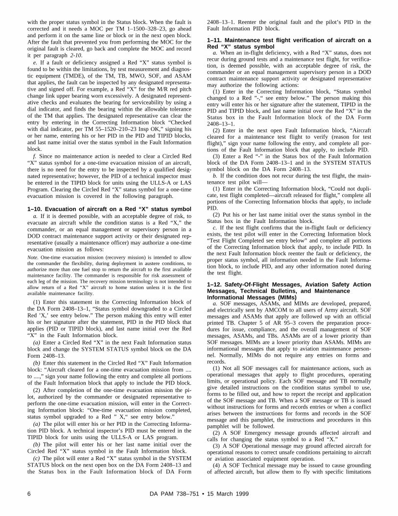
1–10. Evacuation of aircraft on a Red “X” status symbola. If it is deemed possible, with an acceptable degree of risk, to
evacuate an aircraft while the condition status is a Red “X,” thecommander, or an equal management or supervisory person in aDOD contract maintenance support activity or their designated rep-resentative (usually a maintenance officer) may authorize a one-timeevacuation mission as follows:Note. One-time evacuation mission (recovery mission) is intended to allowthe commander the flexibility, during deployment in austere conditions, toauthorize more than one fuel stop to return the aircraft to the first availablemaintenance facility. The commander is responsible for risk assessment ofeach leg of the mission. The recovery mission terminology is not intended toallow return of a Red “X” aircraft to home station unless it is the firstavailable maintenance facility.
(1) Enter this statement in the Correcting Information block ofthe DA Form 2408–13–1, “Status symbol downgraded to a CircledRed ’X,’ see entry below.” The person making this entry will enterhis or her signature after the statement, PID in the PID block thatapplies (PID or TIPID block), and last name initial over the Red“X” in the Fault Information block.
(a) Enter a Circled Red “X” in the next Fault Information statusblock and change the SYSTEM STATUS symbol block on the DAForm 2408–13.
(b) Enter this statement in the Circled Red “X” Fault Informationblock: “Aircraft cleared for a one-time evacuation mission from ....to ....,” sign your name following the entry and complete all portionsof the Fault Information block that apply to include the PID block.
(2) After completion of the one-time evacuation mission the pi-lot, authorized by the commander or designated representative toperform the one-time evacuation mission, will enter in the Correct-ing Information block: “One-time evacuation mission completed,status symbol upgraded to a Red ” X,“ see entry below.”
(a) The pilot will enter his or her PID in the Correcting Informa-tion PID block. A technical inspector’s PID must be entered in theTIPID block for units using the ULLS-A or LAS program.
(b) The pilot will enter his or her last name initial over theCircled Red “X” status symbol in the Fault Information block.
(c) The pilot will enter a Red “X” status symbol in the SYSTEMSTATUS block on the next open box on the DA Form 2408–13 andt h e S t a t u s b o x i n t h e F a u l t I n f o r m a t i o n b l o c k o f D A F o r m
2408–13–1. Reenter the original fault and the pilot’s PID in theFault Information PID block.
1–11. Maintenance test flight verification of aircraft on aRed “X” status symbol
a. When an in-flight deficiency, with a Red “X” status, does notrecur during ground tests and a maintenance test flight, for verifica-tion, is deemed possible, with an acceptable degree of risk, thecommander or an equal management supervisory person in a DODcontract maintenance support activity or designated representativemay authorize the following actions:
(1) Enter in the Correcting Information block, “Status symbolchanged to a Red ”-,“ see entry below.” The person making thisentry will enter his or her signature after the statement, TIPID in thePID and TIPID block, and last name initial over the Red “X” in theS t a t u s b o x i n t h e F a u l t I n f o r m a t i o n b l o c k o f t h e D A F o r m2408–13–1.
(2) Enter in the next open Fault Information block, “Aircraftc l e a r e d f o r a m a i n t e n a n c e t e s t f l i g h t t o v e r i f y ( r e a s o n f o r t e s tflight),” sign your name following the entry, and complete all por-tions of the Fault Information block that apply, to include PID.
(3) Enter a Red “-” in the Status box of the Fault Informationblock of the DA Form 2408–13–1 and in the SYSTEM STATUSsymbol block on the DA Form 2408–13.
b. If the condition does not recur during the test flight, the main-tenance test pilot will—
(1) Enter in the Correcting Information block, “Could not dupli-cate, test flight completed—aircraft released for flight,” complete allportions of the Correcting Information blocks that apply, to includePID.
(2) Put his or her last name initial over the status symbol in theStatus box in the Fault Information block.
c. If the test flight confirms that the in-flight fault or deficiencyexists, the test pilot will enter in the Correcting Information block“Test Flight Completed see entry below” and complete all portionsof the Correcting Information block that apply, to include PID. Inthe next Fault Information block reenter the fault or deficiency, theproper status symbol, all information needed in the Fault Informa-tion block, to include PID, and any other information noted duringthe test flight.
1–12. Safety-Of-Flight Messages, Aviation Safety ActionMessages, Technical Bulletins, and MaintenanceInformational Messages (MIMs)
a. SOF messages, ASAMs, and MIMs are developed, prepared,and electrically sent by AMCOM to all users of Army aircraft. SOFmessages and ASAMs that apply are followed up with an officialprinted TB. Chapter 5 of AR 95–3 covers the preparation proce-dures for issue, compliance, and the overall management of SOFmessages, ASAMs, and TBs. ASAMs are of a lower priority thanSOF messages. MIMs are a lower priority than ASAMs. MIMs areinformational messages that apply to aviation maintenance person-nel. Normally, MIMs do not require any entries on forms andrecords.
(1) Not all SOF messages call for maintenance actions, such aso p e r a t i o n a l m e s s a g e s t h a t a p p l y t o f l i g h t p r o c e d u r e s , o p e r a t i n glimits, or operational policy. Each SOF message and TB normallygive detailed instructions on the condition status symbol to use,forms to be filled out, and how to report the receipt and applicationof the SOF message and TB. When a SOF message or TB is issuedwithout instructions for forms and records entries or when a conflictarises between the instructions for forms and records in the SOFmessage and this pamphlet, the instructions and procedures in thispamphlet will be followed.
(2) A SOF Emergency message grounds affected aircraft andcalls for changing the status symbol to a Red “X.”
(3) A SOF Operational message may ground affected aircraft foroperational reasons to correct unsafe conditions pertaining to aircraftor aviation associated equipment operation.
(4) A SOF Technical message may be issued to cause groundingof affected aircraft, but allow them to fly with specific limitations
6 DA PAM 738–751 • 15 March 1999

and for a certain amount of calendar time, flying hours, componentoperating hours, or rounds fired. Normally, the status symbol will bechanged to a Circled Red “X.”
(5) A Maintenance Mandatory ASAM directs maintenance ac-tions, updates technical manuals, and may call for compliance repor-ting. Normally, the aircraft condition status symbol will be changedto a red horizontal dash “-.”
(6) An Informational ASAM will provide status and informationof a maintenance, technical, or general nature.
(7) An Operational ASAM pertains to aircraft operations, flightprocedures, limitations, or operational policy.
b. All SOF messages, ASAMs, and TBs will be recorded on DAForm 2408–13–1, except for informational ASAMs. Paragraph 5 ofeach message will be used to show the end item aircraft or flightsimulator by MDS that needs to be inspected. For example, para-graph 5 calls for all UH-1M series helicopters to be inspected. Thismessage will be recorded for UH-1M series aircraft only, and willnot be recorded on UH-1H or other series aircraft.Note. Informational ASAMs do not need to be entered on any form orrecord.
(1) Record SOF messages, ASAMs, or TBs on the DA Form2408–13–1 upon receipt, and then complete actions called for.
(a) After the SOF message, ASAM, or TB that calls for aninspection on aircraft, flight simulators, and their repair parts, sys-tems, subsystems, and so forth, is applied enter on the DA Form2408–15 (Historical Record for Aircraft). (See fig 4-3 for an exam-ple of entries).
(b) SOF messages, ASAMs, and TBs that call for an inspectiono n r e p o r t a b l e i t e m s ( c o m p o n e n t s a n d m o d u l e s ) l i s t e d i n T B1 – 1 5 0 0 – 3 4 1 – 0 1 , w i l l b e r e c o r d e d o n t h e D A F o r m 2 4 0 8 – 5 – 1(Equipment Modification Record (Component)) when applied. (Seefig 4-2 for an example of entries).Note. SOF messages, ASAMs, and TBs that apply to reportable items willnot be recorded on DA Forms 2408–5 (Equipment Modification Record) or2408–15. They will be recorded on DA Form 2408–5–1.
(2) SOF messages or ASAMs that call for recurring inspection(s)will be entered on the DA Form 2408–18 (Equipment InspectionList). Enter the needed inspection(s), reference (SOF or ASAMmessage number), frequency of the inspection, and when the inspec-tion is due next.
(3) SOF messages, ASAMs, or TBs that affect reportable compo-nents and modules in supply stock or are uninstalled in maintenanceactivities, enter the SOF or ASAM message number, short or abbre-viated title of message, and phrase “Not complied with” on themateriel condition tag or label attached to the component, module,or carton containing the component. When the SOF message orASAM is applied, enter the information on a DA Form 2408–5–1for the component or module and attach or enclose the form withthe component or module.
(4) When a SOF message or ASAM calls for a reportable compo-nent, or module to be changed, the related DA Forms 2410, and2408–16 or 2408–16–1 will be filled out.
(5) If a SOF message, ASAM, or TB applies to a reportablecomponent or module that does not have a serial number, obtain as e r i a l n u m b e r f r o m t h e S e r i a l N u m b e r R e p o r t i n g R e q u i r e m e n t( S N R R ) o f f i c e A M C O M , A T T N : A M S A M - M M C - R E - F D ,H u n t s v i l l e , A L , v i a e - m a i l , c f o @ r e d s t o n e . a r m y . m i l , o r D e f e n s eSwitched Network (DSN) 897–2900, commercial (256) 313–2900.
(6) When the SOF message, ASAM, or TB calls for changes insignificant historical data, such as, national stock number (NSN),part number (PN), and so forth, see instructions for the specificmaintenance and historical forms or records in chapters 3 and 4.
c. Each maintenance unit or activity where the aircraft is cur-rently assigned must submit a SOF or ASAM Compliance StatusReport per the SOF message, ASAM, or TB instructions.
(1) Include the items listed below in the report:(a) SOF or ASAM message number.(b) Aircraft.
(c) Aircraft serial number (in numerical sequence if more thanone aircraft).
(d) Any other data called for in the SOF message.(2) Send the report as directed by the Major Army Command
(MACOM) or to Commander, AMCOM, ATTN: AMSAM-SF-A,Redstone Arsenal, Huntsville, AL, 35898–5320, by the suspensedate in the reporting section of the SOF or ASAM. Reportingcompliance by e-mail, [email protected] is advised, how-ever, you can data fax to DSN 788–8643 or commercial (256)842–8643.
(3) Do not report compliance of a TB when a report has alreadybeen made on the SOF message or ASAM containing the samesubject matter. The TB will be complied with and reported per theTB instructions only when it has different maintenance actions thancalled for in the previous SOF message or ASAM.
d. Every effort will be made by maintenance personnel at eachlevel of maintenance (AVUM, AVIM, and Depot) to apply, record,and report the application of each SOF message, ASAM, or TB.When the application is not entered on the DA Form 2408–13–1 orhistorical records it is presumed that the SOF message, ASAM, orTB was not applied. If the SOF message, ASAM, or TB is notrecorded as having been applied on the DA Form 2408–13–1 orhistorical records, and the TB publication effective date has beenreached or passed, you should apply, record, and report the SOFmessage, ASAM, or TB per the above procedure.
1–13. Safety-Of-Use Messages, Urgent MWOs, and TBsa. SOU messages are developed, prepared, and electronically sent
by AMCOM to all users of Army nonaircraft equipment listed inappendix D. AR 750–10 covers procedures for issue, compliance,and management of SOU messages, urgent MWOs, and TBs.
b. SOU messages are different from SOF messages and ASAMs,which are covered in paragraph 1-12. Another SOU message, urgentMWO, or TB may follow the first SOU message. This depends onthe type of SOU message first sent. The following explains thedifferent types of SOU messages for aviation associated equipment.
(1) Operational. This message changes operating procedures orplaces limits on equipment usage.
(2) Technical. This message deadlines aviation associated equip-ment, used in support of aircraft and other aviation associated equip-ment, because of materiel or maintenance deficiencies. This type ofmessage calls for modification of the equipment or its components,modules or parts. It will be published later as an urgent MWO.
( 3 ) O n e - T i m e I n s p e c t i o n . T h i s t y p e o f m e s s a g e i m m e d i a t e l ydeadlines equipment and directs inspection procedures before itsnext use. Equipment found to be deficient will remain deadlineduntil the deficiency is corrected. This type of message will not director prescribe a configuration change. SOU one-time inspection mes-sages that are superseded by SOU technical messages will be pub-lished later as emergency TBs.
(4) Advisory or Technical Maintenance or Operational. This typeof message contains new operational or technical maintenance infor-mation vital for equipment operators or maintenance activities. Ad-v i s o r y m e s s a g e s w i l l n o t d e a d l i n e e q u i p m e n t o r d i r e c taccomplishment of a task or maintenance function.
c. Upon receipt of the SOU message, complete the action calledfor, then record the SOU message on DA Form 2408–5–1 for theaffected item. Upon completion of maintenance actions called for bySOU messages or TBs for aviation night vision goggles (NVG),enter information on the DA Forms 2408–15 and 2408–30 (NVGInspection and Maintenance Record) that apply to the aviation nightvision goggles.
d. Report compliance per instructions in the SOU message, ur-gent MWO, or TB.
1–14. Missing historical records or informationa. When aircraft and aviation associated equipment listed in ap-
p e n d i x D , o r r e p o r t a b l e c o m p o n e n t s a n d m o d u l e s l i s t e d i n T B1–1500–341–01 are received without maintenance and historical re-cords do the following:
7DA PAM 738–751 • 15 March 1999

(1) Request missing records from the transferring or shippingactivity.
(2) When missing records or information are not available from(1) above, obtain the information needed from local sources; fore x a m p l e , D D F o r m s 1 5 7 4 ( S e r v i c e a b l e T a g - M a t e r i e l ) , 1 5 7 4 – 1(Serviceable Label-Materiel), or other materiel condition tags/labelsthat were attached to the reportable component or module.
(3) When missing information is obtained, prepare new mainte-nance and historical forms per procedures in chapters 3 and 4.
(4) When (1) and (2) above do not give you needed information,request usage data and other missing information from the appropri-ate 2410 Hotline listed below in (a), (b), (c) or (d). Mark requestsfor “2410 data” . Give complete description (including part numberand serial number) of each component/module and state the recordsa n d i n f o r m a t i o n n e e d e d . I n c l u d e y o u r U n i t I d e n t i f i c a t i o n C o d e(UIC) and state if the item is serviceable or unserviceable, installedor uninstalled. Also include the next higher assembly serial numberif the item is installed.
(a) AVIM/AVUM activities and Aviation Classification RepairActivity Depots (AVCRAD) contact AMCOM 2410 Hotline at DSN8 9 7 – 2 4 1 0 , C o m m e r c i a l ( 2 5 6 ) 3 1 3 – 2 4 1 0 , o r d a t a f a x D S N897–2075, Commercial (256) 313–2075.
(b) Depot/DOD activities and manufacturers contact Field DataD i v i s i o n , C u s t o m e r I n t e r f a c e B r a n c h 2 4 1 0 H o t l i n e a t D S N7 4 6 – 2 8 5 1 , C o m m e r c i a l ( 2 5 6 ) 8 7 6 – 2 8 5 1 , o r d a t a f a x D S N746–5086, Commercial (256) 876–5086.
(c) All Corpus Christi Army Depot (CCAD) personnel contactt h e C C A D 2 4 1 0 H o t l i n e a t D S N 8 6 1 – 4 5 4 4 , C o m m e r c i a l ( 5 1 2 )939–4544, or send requests to Corpus Christi Army Depot, MailS t o p 5 5 , C o r p u s C h r i s t i , T X , 7 8 4 1 9 – 6 1 9 5 , o r d a t a f a x D S N861–3352.
(d) All other personnel requesting data on previously owned gov-ernment aircraft or parts contact the Freedom of Information ActOfficer at the Public Affairs Office at DSN 746–4161, Commercial(256) 876–4161 or mail request to Commander, U.S. Army Aviationand Missile Command, ATTN: AMSAM-PA, Redstone Arsenal,Huntsville, AL, 35898–5230.
(5) When you need information for components, modules, orparts that contain more than one data plate, be sure to locate theproper data plate by inspecting the reportable item and finding thenoun, part number, and NSN that applies. Compare the noun, partnumber, and NSN against the listing in TB 1–1500–341–01 andTM–23P manual that applies. Request usage data or other missinginformation for the correct noun, serial number, part number, andNSN of the reportable item, per subparagraph (4) above.Note. Opening packages, cartons, or containers that contain aircraft compo-nents or modules which are preserved for shipment or storage will only bedone as a last resort to obtain data and then the item will be represerved.
1–15. Aircraft and aviation associated equipment filescontent and management
a. The needed technical publications, forms, and records for air-craft and aviation associated equipment files are:
(1) Operator (TM–10) and maintenance (TM–23) manuals for theaircraft and aviation associated equipment aboard the aircraft.
(2) Operational forms and checklists used to report flight andmaintenance information.
b. Aircraft and aviation associated equipment files will be main-tained as follows:
(1) The commander, AMCOM, is responsible for the operatorand maintenance publications for aircraft, aviation-associated equip-ment, and logbooks. Required forms will be properly filled out andinserted in the logbook for new aircraft issued from the AMCOMproperty account.
(2) The commander or person in equal management position of aDOD contract support maintenance activity where the aircraft isassigned will:
(a) Obtain the needed publications and blank forms that are notsupplied by AMCOM; and fill out the forms per this pamphlet.
( b ) K e e p e n o u g h c o p i e s o f t e c h n i c a l p u b l i c a t i o n s a n d b l a n k
forms to support assigned aircraft. Each unit operating aircraft willkeep one complete set of technical publications for each flightsection to be sure of prompt deployability. Local commanders willdetermine if more sets of publications are needed.
(c) Be sure that current changes, revisions, and data are posted tothe aircraft files and deletions are not made unless prescribed byAMCOM.
(d) Be sure that the aircraft and aviation associated equipmentfiles are kept in the location listed in subparagraphs 1-15c, d, e, andf.
(e) Be sure that all classified technical publications are safeguar-ded as per AR 380–5.Note. Nonstandard aircraft will use operator manuals (–10) and maintenancemanuals (–23) that apply.
c. The publications and forms below will be located in the air-craft during operation and when transferred.
(1) Operator’s Checklist (CL).(2) Operator’s Manual (TM 10) including changes and related
SOF or TBs.(3) Current DD Form 365–4 (Weight and Balance Clearance
Form F-Transport/Tactical) (See AR 95–3, chapter 6)(4) Equipment Logbook Assembly consisting of the items below:(a) Logbook binder.(b) Turbine Engine Health Indicator Test (HIT) Exhaust Gas
Temperature (EGT) log, if applicable.(c) Preventive Maintenance Daily (PMD) Checklist or Preventive
Maintenance Service Manuals (Not required for aircraft not usingArmy TMs; such as C–11, C–12, C–21, C–23, C–26, TH–67 seriesaircraft).
(d) Aircraft logbook forms:1. A Form 2408–31 (Aircraft Identification Card).2. A Form 2408 (Equipment Log Assembly (Records)).3. A Form 2408–4–1 (Weapon Record Data).4. A Form 2408–4–2 (Weapon Sighting Data (OH-58D)).5. A Form 2408–4–3 (Weapon Sighting Data (AH-64A only)).6. A Form 2408–12 (Army Aviator’s Flight Record).7. A Form 2408–13 (Aircraft Status Information Record).8 . A F o r m 2 4 0 8 – 1 3 – 1 ( A i r c r a f t I n s p e c t i o n a n d M a i n t e n a n c e
Record).9. A Form 2408–13–2 (Related Maintenance Actions Record).1 0 . A F o r m 2 4 0 8 – 1 3 – 3 ( A i r c r a f t T e c h n i c a l I n s p e c t i o n
Worksheet).11. A Form 2408–14–1 (Uncorrected Fault Record (Aircraft)).12. A Form 2408–18 (Equipment Inspection List).13. D Form 1896 (Jet Fuel Identaplate) (white) or DD Form 1897
(AVGAS Identaplate) (purple).d. Even though all the proper forms in subparagraph 1-15c(4)(d)
above are to be kept in the aircraft logbook, only four forms arec o n s i d e r e d t h e “ F l i g h t P a c k . ” T h e f o u r f o r m s a r e D A F o r m s2408–13, 2408–13–1, 2408–13–2, and 2408–13–3. A unique pagenumbering system for the Flight Pack was developed for the pilot,crewmembers, and maintenance personnel using and making entrieson aircraft logbook forms. Of the four forms in the Flight Pack onlyt h r e e o f t h e m a r e g i v e n p a g e n u m b e r s ; t h e y a r e D A F o r m s2408–13–1, 2408–13–2, and 2408–13–3. The DA Form 2408–13 inthe Flight Pack does not have a page number. It does have a“Number of pages in the Flight Pack” entry, but this form will notbe counted as a page in the Flight Pack. An example of the uniquenumbering system: An aircraft logbook contains one DA Form2 4 0 8 – 1 3 , t h r e e D A F o r m s 2 4 0 8 – 1 3 – 1 , a n d o n e D A F o r m2408–13–2. The first DA Form 2408–13–1 will be page 1, thesecond will be page 2, and the third will be page 3. The DA Form2408–13–2 becomes page 4, which makes the number of pages inthe Flight Pack four. The number 4 will then be entered in the“Number of pages in flight pack” block on the DA Form 2408–13.The numbering system provides the pilot, crew chief, and qualitycontrol inspectors with an accounting system of how many formsare in the flight pack. If a DA Form 2408–13–1 or 2408–13–2 wasremoved from the aircraft logbook by mistake it could be detectedby the pilot or crew chief. When the missing form is placed back in
8 DA PAM 738–751 • 15 March 1999

the flight pack, the pilot can complete their review of the aircraftstatus, condition, and other important entries before flight. If a DAForm 2408–13–3 is added to the aircraft logbook, it becomes a partof the flight pack and is numbered as a page in the flight pack.
e. The historical forms and records listed below will not be keptin the aircraft. Maintenance personnel who do organizational, sup-port maintenance, quality control functions on the aircraft, will re-tain them in the quality control office or other suitable location foreasy access.
(1) Maintenance historical forms and records:(a) DA Form 2408–5 (Equipment Modification Record).( b ) D A F o r m 2 4 0 8 – 5 – 1 ( E q u i p m e n t M o d i f i c a t i o n R e c o r d
(component)).(c) DA Form 2408–15 (Historical Record for Aircraft).(d) DA Form 2408–15–2 (Aircraft Vibration Record).(e) DA Form 2408–16 (Aircraft Component Historical Record).(f) DA Form 2408–16–1 (History Recorder, Component, Module
Record).(g) DA Form 2408–17 (Aircraft Inventory Record).(h) DA Form 2408–19 (Aircraft Engine Turbine Wheel Historical
Record).( i ) D A F o r m 2 4 0 8 – 1 9 – 1 ( T 5 3 / T 5 5 T u r b i n e E n g i n e A n a l y s i s
check Record).(j) DA Form 2408–19–2 (T700 Turbine Engine Analysis Check
Record).(k) DA Form 2408–19–3 (Engine Component Operating Hours
Record).(l) DA Form 2408–20 (Oil Analysis Log).(m) Turbine Engine Health Indicator Test (HIT) or Exhaust Gas
Temperature (EGT) worksheets which apply.(2) Aviation life support equipment (ALSE) forms and records:(a) DA Form 2408–21 (Life Raft Inspection Record).(b) DA Form 2408–22 (Helmet and Oxygen Masks/Connector
Inspection Record).( c ) D A F o r m 2 4 0 8 – 2 3 ( S u r v i v a l R a d i o / E m e r g e n c y L o c a t i o n
Transmitter Inspection Record).(d) DA Form 2408–24 (Survival Kit Inspection and Maintenance
Record).( e ) D A F o r m 2 4 0 8 – 2 5 ( M e s h N e t S u r v i v a l V e s t I n s p e c t i o n
Record).(f) DA Form 2408–26 (Life Preserver Inspection Record).(g) DA Form 2408–27 (Life Preserver Data).(h) DA Form 2408–28 (Oxygen Console Service Record).( i ) D A F o r m 2 4 0 8 – 2 9 ( A n t i - E x p o s u r e C o v e r a l l s I n s p e c t i o n
Record).( j ) D A F o r m 2 4 0 8 – 3 0 ( N V G I n s p e c t i o n a n d M a i n t e n a n c e
Record).(3) Completed forms and records will be processed and disposed
of as per chapters 2, 3, 4, and 5.(4) Completed Maintenance Inspection Checklist for scheduled
maintenance, such as a phase, or any other scheduled maintenancewill be processed and disposed of per chapter 3.
f. The publications listed below will be maintained and kept up-to-date.
(1) MTF manual.(2) AVUM and AVIM manuals (–10 and –23).(3) AVUM and AVIM aircraft repair parts and special tools list
(–23P).(4) AVUM and AVIM aircraft engine maintenance manual (–23).(5) AVUM and AVIM aircraft engine repair parts and special
tools list (–23P).( 6 ) O r g a n i z a t i o n a l m a i n t e n a n c e m a n u a l : E l e c t r o n i c E q u i p m e n t
Configuration (–20 or –23).(7) Organizational maintenance repair parts and special tools lists
manual: Electronic Configuration (–20P or –23P).( 8 ) O r g a n i z a t i o n m a i n t e n a n c e m a n u a l : A r m a m e n t s u b s y s t e m
(–12).(9) Maintenance repair parts and special tools list manual: Arma-
ment subsystem (–20P or –23P).
(10) Automated Weight and Balance System, Version 6.0. Ap-plies to maintenance units or activities that have an automatedweight and balance program. Software and instructions for this sys-t e m a r e a v a i l a b l e a t A M C O M , A M S A M - M M C - R E - F D , D S N746–5219 or commercial (256) 876–5219.
(11) Army Aviation Maintenance Engineering Manual, Weightand Balance (TM 1–1500–342–23).
1–16. Records to accompany aircrafta. U.S. Army aircraft listed in appendix D will have, on board,
the publications and forms listed in subparagraph 1-15c at the timeof property transfer from one account to another, or during deploy-ment to field exercises or combat operations. Other forms, records,a n d p u b l i c a t i o n s l i s t e d i n s u b p a r a g r a p h 1 - 1 5 e w i l l b e s h i p p e dseparately to the unit or activity receiving, operating, or maintainingthe aircraft within 24 hours of the aircraft’s departure from thetransferring or deploying unit or activity. Do not load the items, insubparagraph 1-15e, aboard the aircraft, cargo aircraft, barge, shipor vehicle that is transporting the aircraft being transferred or de-ployed. Do not load items listed in subparagraph 1-15e in onecontainer, such as a conex or footlocker. This will prevent loss ordamage of valuable information on forms and records. The methodof packaging and shipping of these items will be accomplishedusing air courier service, such as Airborne Express, United ParcelService (UPS), Federal Express, or the quickest and safest waypossible. The transferring or deploying unit or activity must be ableto track the items if the shipment does not arrive at the receivingunit or activity.
b. ULLS-A units will download the records to magnetic media(diskette) to facilitate the uploading of aircraft records at the gainingorganization if they have ULLS-A capabilities. The QC will reviewall operational/historical records to determine serviceability stand-ards and make entries to records requiring notations of the transfer.The manual/hard copy aircraft logbook and historical records will becurrent and identical with the aircraft records downloaded to thediskette(s). The manual/hard copy records will be required if thegaining organization is not operating under ULLS-A.
c. All aircraft forms, records, and files will be sent to the gainingunit or activity when the aircraft is—
(1) Transferred to another unit or activity (includes the 6-monthfile).
(2) Delivered for repair, at the request of a higher-level mainte-nance activity.
(3) Delivered to a depot level, organic, or DOD contract supportm a i n t e n a n c e a c t i v i t y f o r r e p a i r , o v e r h a u l , m o d i f i c a t i o n , o rmodernization.
1–17. Excess, Deteriorated, Crash Damaged, or DestroyedU.S. Army Aircraft Transferred to Defense Reutilizationand Marketing Office
a. Flyable or deteriorated aircraft designated as excess to theArmy’s needs by AMCOM, and for sale or donation per DOD4160.21M, will be transferred to the local Defense Reutilization andMarketing Office (DRMO). The aircraft data plate will remain at-t a c h e d t o f l y a b l e a i r c r a f t , e x c e p t f o r t h e a i r c r a f t l i s t e d i n s u b -paragraph (d) below. Nonflyable aircraft will have the data plateremoved and a photocopy made of the data plate. The photocopywill remain with the aircraft and the data plate will be mailed toAMCOM. The complete logbook, including all forms, records, files,and publications, will be transferred with the aircraft. The activitytransferring the aircraft to the DRMO will complete the followingactions:
(1) Do a serial number inventory of all reportable componentsand subcomponents listed in TB 1–1500–341–01 or ULLS-A Com-ponent Legitimate Code File (LCF), and entered on DA Forms2408–16 and 2408–16–1. Due to inaccessibility of some subcom-ponents, such as internal engine subcomponents, they cannot beinventoried. Compare the serial number inventory with the DAForms 2408–16 and 2408–16–1 to be sure that the forms are currentand accurate.
(2) Review current DA Form 2408–20 to make sure that all
9DA PAM 738–751 • 15 March 1999

information is current. Notify servicing AOAP laboratory that theaircraft and components are being transferred.
(3) When AMCOM issues a “Save List” containing reportablecomponents listed in TB 1–1500–341–01 or ULLS-A ComponentLCF, submit a DA Form 2410, copy 1, for removal of the item(s)and line out the item(s) on the DA Form 2408–16 or 2408–16–1.
(4) Remove the data plate from AH-1, AH-64 and OV-1. Mail it,along with the records or a copy of the ULLS-A transfer disk toC o m m a n d e r A M C O M , A T T N : A M S A M - M M C - R E - F D ( C D R A ) ,Redstone Arsenal, Hunstville, AL 35898–5230. Make sure that theULLS-A software version is annotated on the disk label.
(5) Make a close-out entry on the DA Form 2408–15 as follows:“Close-out Statement: All items on the DA Form 2408–16 havebeen verified as installed, or removed items have been lined out.Aircraft processed to DRMO at (location of DRMO) on (date) by(name of facility or unit transferring aircraft) at (total aircraft hours).Aircraft data plate (has/has not) been removed, (include the reasonfor transfer)” followed by the PID, unit, and phone number of theindividual making the entry. If the engines are equipped with His-tory Recorders enter the history recorder serial numbers and read-ings for each engine, with the engine serial number. ULLS-A usersmay mail a transfer disk in lieu of making copies. Annotate thesoftware version on the disk label.
(6) Make a readable photocopy of the current DA Form 2408–13,all DA Forms 2408–15, 2408–16 and 2408–16–1 in the historicalrecord file and the AMCOM “Save List” and send to CommanderAMCOM, ATTN: AMSAM-MMC-RE-FD (CDRA), Redstone Ar-senal, Hunstville, AL 35898–5230. The information contained onthese forms must be current and accurate. The photocopy of theseforms will be used by AMCOM to complete the DA Form 2410,Copy 3, Loss to the Army Inventory, for all reportable componentsand subcomponents installed on the aircraft at the time of transfer.
b. Crash damaged or destroyed aircraft will be transferred to thel o c a l D R M O a f t e r d i s p o s i t i o n i n s t r u c t i o n s a r e r e c e i v e d f r o mAMCOM. The activity possessing the aircraft before transfer to theDRMO will complete the following actions:
(1) Do a serial number inventory of all reportable componentsand subcomponents listed in TB 1–1500–341–01 or ULLS-A Com-ponent LCF, and entered on DA Forms 2408–16 and 2408–16–1.Some subcomponents can not be inventoried because of inacces-s i b i l i t y o f t h e s u b c o m p o n e n t s , s u c h a s i n t e r n a l e n g i n e s u b c o m -ponents. Compare the serial number inventory with the DA Forms2408–16 and 2408–16–1 to be sure that the forms are current andaccurate. The DA Forms 2408–16 and 2408–16–1 will be used byAMCOM to complete the DA Form 2410, Copy 3 Loss to the ArmyInventory, for all reportable components and subcomponents in-stalled on the aircraft at the time of transfer.
(2) Notify servicing AOAP laboratory that the aircraft and com-ponents are being transferred.
(3) When AMCOM issues a “Save List” containing reportablecomponents listed in TB 1–1500–341–01 or ULLS-A ComponentLCF, submit a DA Form 2410, Copy 1, for removal of the item(s)and line out the item(s) on the DA Form 2408–16 or 2408–16–1. Acopy of the “Save List” must be furnished to AMCOM with theaircraft records.
(4) Remove the aircraft data plate and mail to AMCOM alongwith the forms and records or ULLS-A transfer disk. Annotate theULLS-A software version on the disk label.
(5) Make a close-out entry on the DA Form 2408–15 as follows:“Close–out Statement: All items on the DA Form 2408–16 havebeen verified as installed, or removed items have been lined out.Aircraft processed to DRMO at (location of DRMO) on (date) by(name of facility or unit transferring aircraft) at (total aircraft hours).Data Plate Sent to AMCOM ” state the reason for transfer, followedby the unit, PID, and phone number of the commander’s designatedrepresentative having jurisdiction over the aircraft at the time ofdisposal. If the engines are equipped with History Recorders enterthe history recorder serial number and readings for each engine,with engine serial number.
(6) Mail the following aircraft records and data plate to Com-m a n d e r , A M C O M , A T T N : A M S A M - M M C - R E - F D ( C D R A ) ,Redstone Arsenal, Hunstville, AL 35898–5230:
(a) Current DA Form 2408–13.(b) A Form 2408–5.(c) A Form 2408–5–1.(d) A Form 2408–15.(e) A Form 2408–15–2.(f) A Form 2408–16.(g) A Form 2408–16–1.(h) A Form 2408–19.(i) A Form 2408–19–1.(j) A Form 2408–19–2.(7) Destroy the forms listed below.(a) A Form 2408–13 (except the current form).(b) A Form 2408–13–1.(c) A Form 2408–13–2.(d) A Form 2408–14–1.(e) A Form 2408–17.(f) A Form 2408–18.(g) A Form 2408–20.(h) The aircraft 6-month file.(i) Aircraft weight and balance file.
1–18. Aircraft transferred to other Government agenciesand the Military Assistance Program
a. US Army aircraft, flyable or nonflyable, may be transferred toother Government agencies or state and local agencies when desig-nated by AMCOM. The aircraft data plate will remain attached tothe aircraft. The complete logbook assembly, forms, records, files,publications, and data plate will be transferred with the aircraft,except the DA Forms 2408–12, on file in the operations office. Theactivity possessing the aircraft before transfer will complete thefollowing actions:
(1) Do a serial number inventory of all reportable componentsand subcomponents listed in TB 1–1500–341–01 or ULLS-A Com-ponent LCF, and entered on DA Forms 2408–16 and 2408–16–1.Some subcomponents can not be inventoried due to inaccessibilityo f t h e s u b c o m p o n e n t s , s u c h a s , i n t e r n a l e n g i n e s u b c o m p o n e n t s .Compare the serial number inventory with the DA Forms 2408–16and 2408–16–1 to be sure that the forms are current and accurate.
(2) Make a close-out entry on the DA Form 2408–15 as follows:“Close-out Statement: All items on the DA Form 2408–16 havebeen verified as installed, or removed items have been lined out.Aircraft transferred to (location of receiving organization) on (date)for (reason for transfer) by (name of facility or unit transferringaircraft) at (total aircraft hours). Data Plate remained installed.”State the reason for transfer, followed by the PID, unit, and phonen u m b e r o f t h e i n d i v i d u a l m a k i n g t h e e n t r y . I f t h e e n g i n e s a r eequipped with History Recorders enter the history recorder serialnumbers and readings for each engine, with engine serial number.ULLS-A users may mail a transfer disk instead of making copies.Annotate the software version on the disk label.
(3) Review the DA Forms 2408–5, 2408–5–1 and 2408–15 tomake sure that all the MWOs, SOF messages, ASAMs, and TBsthat apply are complied with and entered.
(4) Complete any scheduled or special maintenance inspectionsdue.
( 5 ) T r a n s f e r a l l u n c o r r e c t e d f a u l t s l i s t e d o n t h e D A F o r m2408–14–1 to a DA Form 2408–13–1, Fault Information block(s).Place the DA Form 2408–14–1 in the aircraft 6-month file after allfaults have been transferred.
(6) Perform a final aircraft inventory and annotate DA Form2408–17 per instructions in chapter 4.
(7) Review current DA Form 2408–20 to make sure that allinformation is current. Notify servicing AOAP laboratory that theaircraft and components are being transferred.
(8) Send a readable photocopy of the current DA Form 2408–13,all DA Forms 2408–15, 2408–16 and 2408–16–1 in the historicalf i l e a n d t h e A M C O M “ S a v e L i s t ” t o C o m m a n d e r , A M C O M ,A T T N : A M S A M - M M C - R E - F D ( C D R A ) , R e d s t o n e A r s e n a l ,
10 DA PAM 738–751 • 15 March 1999

Hunstville, AL 35898–5230. The forms will be used by AMCOM tocomplete the DA Form 2410s, Copy 3 Loss to the Army Inventory,for all reportable components and subcomponents installed on theaircraft at the time of transfer. ULLS-A users may mail a transferdisk instead of making copies. Annotate the software version on thedisk label.
b. Aircraft transferred to the Military Assistance Program willfollow the procedures for transfer of a U.S. Army aircraft to otherU . S . G o v e r n m e n t a g e n c i e s a n d t h e i n s t r u c t i o n s i n t h e m e s s a g eauthorizing transfer of the aircraft.
1–19. Aircraft used for static display or transferred tomuseums
a. Aircraft transferred for use as a static display. The activitypossessing the aircraft before transfer will complete the followingactions:
(1) Do a serial number inventory of all reportable componentsand subcomponents listed in TB 1–1500–341–01 or ULLS-A Com-ponent LCF, and entered on DA Forms 2408–16 and 2408–16–1.Some subcomponents cannot be inventoried because of inacces-s i b i l i t y o f t h e s u b c o m p o n e n t s , s u c h a s i n t e r n a l e n g i n e s u b c o m -ponents. Compare the serial number inventory with the DA Forms2408–16 and 2408–16–1 to be sure that the forms are current andaccurate. The DA Forms 2408–16 and 2408–16–1 will be used byAMCOM to complete the DA Form 2410s, Copy 3 Loss to theArmy Inventory, for all reportable components and subcomponentsinstalled on the aircraft at the time of transfer.
(2) Review current DA Form 2408–20 to make sure that allinformation is current. Notify servicing AOAP laboratory that theaircraft and components are being transferred.
(3) When AMCOM issues a “Save List” containing reportablecomponents listed in TB 1–1500–341–01 or ULLS-A ComponentLCF, submit a DA Form 2410, Copy 1, for removal of the item(s)and line out the item(s) on the DA Form 2408–16 or 2408–16–1. Acopy of the “Save List” must be furnished to AMCOM with theaircraft records.
(4) Make a close-out entry on the DA Form 2408–15 as follows:“Close-out Statement: All items on the DA Form 2408–16 havebeen verified as installed or items removed have been lined out.A i r c r a f t t r a n s f e r r e d t o ( l o c a t i o n a n d o r g a n i z a t i o n ) o n ( d a t e ) b y(name of facility or unit transferring aircraft) at (total aircraft hours).Data Plate Sent to AMCOM,” followed by the signature, unit, andphone number of the commander’s designated representative havingjurisdiction over the aircraft at the time of transfer. If the enginesare equipped with history recorders enter the history recorder serialn u m b e r s a n d r e a d i n g s f o r e a c h e n g i n e , w i t h t h e e n g i n e s e r i a lnumber.
(5) Remove the data plate and make a photocopy of the dataplate. The photocopy will remain with the aircraft. Mail the aircraftdata plate and the following records or ULLS-A transfer disk (anno-tate ULLS-A software version on the disk label) to Commander,AMCOM, ATTN: AMSAM-MMC-RE-FD (CDRA), Redstone Ar-senal, Hunstville, AL 35898–5230:
(a) Current DA Form 2408–13.(b) DA Form 2408–5.(c) DA Form 2408–5–1.(d) DA Form 2408–15.(e) DA Form 2408–15–2.(f) DA Form 2408–16.(g) DA Form 2408–16–1.(h) DA Form 2408–19.(i) DA Form 2408–19–1.(j) DA Form 2408–19–2.(k) DA Form 2410.(6) Destroy the forms listed below.(a) DA Form 2408–13 (except the current form).(b) DA Form 2408–13–1.(c) DA Form 2408–13–2.(d) DA Form 2408–14–1.(e) DA Form 2408–17.
(f) DA Form 2408–18.(g) DA Form 2408–20.(h) Aircraft 6-month file.(i) Aircraft Weight and Balance file.b. Aircraft Transferred to Museums(1) Records of aircraft that will be used in museum displays may
remain with the aircraft provided the aircraft has significant histori-cal value, or the records will be used as part of the display. Whenthe complete logbook assembly, forms, records, files and publica-tions will be transferred with the aircraft perform the following:
(a) A serial number inventory of all reportable components andsubcomponents listed in TB 1–1500–341–01 or ULLS-A Compo-nent LCF and entered on DA Forms 2408–16 and 2408–16–1. Somesubcomponents can not be inventoried because of inaccessibility,such as, internal engine subcomponents. Compare the serial numberinventory with the DA Forms 2408–16 and 2408–16–1 to be surethat the forms are accurate and current.
(b) When AMCOM issues a “Save List” containing reportablecomponents listed in TB 1–1500–341–01 or ULLS-A ComponentLCF, submit a DA Form 2410, Copy 1, for removal of the item(s)and line out the item(s) on the DA Form 2408–16 or 2408–16–1. Acopy of the “Save List” must be furnished to AMCOM with theaircraft records.
(c) Make a close-out entry on the DA Form 2408–15 as follows:“Close-out Statement: All items on the DA Form 2408–16 havebeen verified as installed or items removed have been lined out.Aircraft transferred to (location of receiving museum) on (date) for(reason for transfer) by (name of facility or unit transferring aircraft)at (total aircraft hours). Data Plate remained installed.” followed bythe signature, unit, and phone number of the individual making theentry. If the engines are equipped with History Recorders enter thehistory recorder serial numbers and readings for each engine, withthe engine serial number.
(d) A readable photocopy of the current DA Form 2408–13, allDA Forms 2408–15, 2408–16 and 2408–16–1 in the historical filea n d t h e A M C O M “ S a v e L i s t ” w i l l b e s e n t t o C o m m a n d e r ,AMCOM, ATTN: AMSAM-MMC-RE-FD (CDRA), Redstone Ar-senal, Hunstville, AL 35898–5230. The copies of these forms willbe used by AMCOM to complete the DA Forms 2410, Copy 3 Lossto the Army Inventory, for all reportable components and subcom-ponents installed on the aircraft at the time of transfer. ULLS-Ausers may mail a transfer disk in lieu of making copies. Annotatethe software version on the disk label.
(2) When the records are not to be transferred with the aircraft,follow the procedures in subparagraph 1–19a(5) and (6).
(3) The aircraft data plate will be removed and a photocopy ofthe data plate will be made. The photocopy of the data plate willremain with the aircraft and the data plate will be mailed to Com-m a n d e r , A M C O M , A T T N : A M S A M - M M C - R E - F D ( C D R A ) ,Redstone Arsenal, Hunstville, AL 35898–5230.
1–20. Aircraft and components used for maintenancetraining
a. Aircraft designated as Category A or B maintenance trainingaircraft (MTA) will keep all forms and records required by para-graph 1–15 above. Send copies of the current DA Form 2408–13,last page of aircraft DA Form 2408–15, and all DA Forms 2408–16and 2408–16–1.
b. When an aircraft is redesignated as a MTA the procedures insubparagraph 1–18a will be followed.
c. When aircraft components or modules are designated as struc-tural training devices, dynamic training devices, or isolated aeronau-tical elements, to be used in a training environment, a DA Form2410, Copy 3 Loss to the Army Inventory, must be submitted toAMCOM for each reportable item.
d. Section XIII of TM 1–1500–328–23 provides policy for train-ing aircraft.
1–21. U.S. Army aircraft loaned or bailed, or procured forother U.S. Government departments and agenciesU.S. Army aircraft forms, records, files, and publications will go
11DA PAM 738–751 • 15 March 1999

with aircraft that are loaned or bailed to other U.S. Governmentdepartments or agencies, industrial, and research activities. Upkeepof forms, records, files, and publications for aircraft loaned or bailedwill be completed by the activity operating, maintaining, storing, ordisposing of the aircraft per this pamphlet.
1–22. Classifying records and reportsData displaying on hand quantities of end-item aircraft, such as theDA Form 1352 (Army Aircraft Inventory, Status, and Flying Time)for any size unit or organization, such as, company, squadron, bat-talion, brigade, or division of the U.S. Army is unclassified. The on-hand information is unclassified whether it is shown by single air-craft, multiple aircraft, consolidated, rolled up, or otherwise arrayed.However, any record, report, or display that shows both on handquantities and authorized quantities is to be classified at a minimumas confidential at corps level and above. Exceptions to the guidanceapply where it is listed in aircraft or aviation associated equipmentsecurity classification guides. Protect confidential information perAR 380–5. Declassify 1 full year after the date of the report.
1–23. Unit Level Logistics System-Aviation and LogbookAutomated System
a. An automated data processing (ADP) system to improve main-tenance and logistics management throughout the Army aviationcommunity has been developed, tested, approved, and is in thep r o c e s s o f b e i n g f i e l d e d . T h e n e w a n d m o r e c o m p l e x a i r c r a f tweapon systems and aviation associated equipment combined withthe streamlined fighting force, create a need for a more efficientrecord keeping system that will provide the commander and mainte-nance managers, at all levels, an improved management tool. TheADP system called LAS and developed by AMCOM, was fine-tuned and renamed Unit Level Logistics System-Aviation (ULLS-A), incorporated into the STAMIS ULLS, and is the standard sys-tem being fielded to all Army aviation field units. ULLS-A inter-faces with SAMS and the STAMIS called Standard Army RetailSupply System (SARSS). Upon completion of any other automatedrelated systems under development, such as, the flight data recorderfault analyzer and electronic aviation technical manuals, steps willbe taken to interface with these systems.
b . C o m m a n d e r s a r e r e s p o n s i b l e f o r t h e s e c u r e o p e r a t i o n o fULLS-A sites. This responsibility includes stored data, hardware,a n d s o f t w a r e . G u i d e l i n e s f o r a u t o m a t i o n s e c u r i t y p r o g r a m s a r efound in AR 380–19. ULLS-A was developed with automated pro-tection mechanisms available for use. All ULLS-A users will befamiliar with ULLS-A Security Features User’s Guide, which ex-plains specifically how the security mechanisms work, so that usersare able to consistently and effectively protect ULLS-A information.
c. All procedures in this pamphlet apply to maintenance person-nel using ULLS-A/LAS or the manual way of keeping forms andrecords. When different instructions apply to ULLS-A or LAS users,they are identified in the individual forms and records instructions.An End User Manual (AISM-25-L3P-AWD-ZZZ-EM) has been pro-vided to ULLS-A users. This manual provides the information nec-essary to use the system effectively and explains the “How To” ofthe functions on ULLS-A.
d. Electronic forms were designed and developed during test anddevelopment of ULLS-A and LAS and are completely compatiblewith current forms, records, and procedures. All DA operational,maintenance, and historical forms used in ULLS-A or LAS pro-grams have been revised to include an “E” following the number,for example, DA Form 2408–15–E. The “E” forms are electroni-cally generated and filled with data at the same time. The “E” formsare filled out the same as the DA hard copy forms, except a few ofthe electronic forms have been designed to add, delete, or combineinformation automatically. Only the DA hard copy forms, withoutthe “E,” will be preprinted, stocked, stored, and issued. The hardcopy forms will be used as a back up system when the ULLS-A orLAS computer hardware or software becomes inoperative.
e. There is no requirement to have your organization maintaintwo sets of logbook forms while using ULLS-A or LAS. Once the
conversion process from old historical (manual) forms to the newhistorical (automated) forms is completed, the old converted formsare for reference use only. The vision of the future is to have apaperless logbook; therefore, all historical forms will be converted.Old converted forms will be maintained in a safe place for at least 6months. After 6 months, if the maintainer is satisfied that the con-v e r t e d r e c o r d s a r e c o r r e c t t h e o l d c o n v e r t e d f o r m s m a y b edestroyed.
f. All faults and inspections performed will be entered in theULLS-A data base on a daily basis. This action may be delayedwhen away from home station, or the ULLS-A/LAS system is inop-erative. Currently, related maintenance actions entered on the DAForm 2408–13–2 will not be entered in the ULLS-A/LAS data base.All manhours expended in correcting a fault or completing an in-spection on the DA Form 2408–13–2 must be totaled and entered inthe Correcting Information block on the corresponding DA Form2408–13–1 for input into the ULLS-A/LAS data base.
g. The logbook flight pack will be closed out at the end of themission day or before the first flight of the next mission day. Theperson printing the flight pack will be sure that all open faults areprinted on the new DA Form 2408–13–1. He or she will place “CF”in the Action Taken block and enter his or her PID in the first PIDblock of the Correcting Information block of the old DA Form2408–13–1 for the open fault. The printing of the flight pack maybe delayed when away from home station or the ULLS-A or LASsystem is inoperative.
h . U L L S - A w o r k s w i t h t h e A r m y M a t e r i e l S t a t u s S y s t e m(AMSS), which is the automated system for reporting readiness foraircraft and aviation systems that replaces the DA Forms 1352/1352–1. ULLS-A automatically triggers the AMSS system when a“X” Aor a circled “X” status symbol for faults, deficiencies, orconditions entered on a DA Form(s) 2408–13–1 or 2408–13–3 ischanged. A problem is encountered when an aircraft has no faults,deficiencies, or conditions with a “X” or circled “X” status symbolon the DA Form(s) 2408–13–1 or 2408–13–3, but has faults, defi-ciencies, or conditions with a lesser status symbol requiring a DAForm 2408–13–2 for related maintenance actions, and one of therelated maintenance actions has a “X” status symbol, which affectsthe readiness reporting. Since the DA Form 2408–13–2 is not auto-mated and related maintenance actions are not entered into theULLS–A data base, AMSS is not being updated to show the currentand correct readiness data. Until this problem is resolved the follow-ing instructions will be used:
(1) As soon as a “X” status condition, which affects the readinessreporting is entered on a DA Form 2408–13–2, a “X” entry will bemade on the DA Form 2408–13–1 or 2408–13–3. Make the entry onthe DA Form 2408–13–1 or 2408–13–3 in the first open FaultInformation block. Enter a “X” status symbol in the STATUS block,the correct system code in the SYS block, the date the status went toa “X” in the DATE block, the time of day that the status went to a“X” in the TIME block, and the PID of the person making the entryin the PID block. Make an entry the same as the original fault,deficiency, or condition (that required the DA Form 2408–13–2)followed by “in process” in the FAULT/REMARKS section. Fill inthe rest of the blocks per paragraph 2–10 DO NOT sign off theoriginal fault, deficiency, or condition until the corrective action iscompleted.
(2) The Correcting Information block for the “X” entry will becorrected when the original fault, deficiency, or condition is com-pleted. The person entering the corrective action will enter his or herPID in the PID block, and will enter “0.1” in the HOURS block.
(3) The Correcting Information block for original fault, deficien-cy, or condition will be completed per paragraph 2–10. Enter thedate the fault was corrected in the DATE block, and enter the timethe fault was corrected in the TIME Block.
i. ULLS-A and LAS were designed to print the forms and re-cords on card stock, the same size as the logbook. The logbookpaper has been assigned NSN 7530–01–392–4969, Card, TabulatingMachine, Continuous Flat Fold. There is no requirement that thelogbook paper has to be used. It may be used, or regular printerpaper may be used to print the forms and records. Entering the
12 DA PAM 738–751 • 15 March 1999

aviation data into the ULLS-A/LAS data base, on a daily basis anddoing regular backups, ensures that the data will be available if thepaper form is damaged or lost and a new form can be printed.
j. ULLS-A units will provide an automated input monthly toC o m m a n d e r , A M C O M , A M S A M - M M C - R E - F F ( U L L S - A ) ,Redstone Arsenal, Hunstville, AL 35898–5230. AMCOM will pro-vide procedures to ULLS-A units on what the data requirement willbe.
k. ULLS-A units finding a problem with the program will submita DA Form 5005–R, Engineering Change Proposal-Software (ECP-S) to USA Information Systems, Software Development Center Lee,ATTN: ASQB-ILS-D, Stop L-74, Ft. Lee, VA 23801–6065 andsend a copy to CDR, AMCOM, ATTN: AMSAM-MMC-RE-FF,Redstone Arsenal, Hunstville, AL 35898–5230. The ULLS-A cus-tomer assistance hot line number is DSN 687–1051.
1–24. Aircraft Quality Control Programa. To be sure that the aircraft and aviation associated equipment
maintenance operations is providing the best possible support tosustain aircraft safety and combat readiness, AVUM, AVIM, andDepot-level maintenance activities will—
(1) Establish an effective QC and Technical Inspection (TI) pro-gram as outlined in FM 1–500 (Army Aviation Maintenance, chap-ter 8, Army Quality Control and Technical Inspection).
(2) Maintain and support the QC program by meeting the follow-ing objectives:
(a) Assignment of only skilled and qualified maintenance person-nel to perform QC and TI functions.
(b) Establish QC and TI procedures to assure quality mainte-nance work is being performed on aircraft, components, modules,s y s t e m s , s u b s y s t e m s , a v i a t i o n a s s o c i a t e d e q u i p m e n t , d i a g n o s t i cequipment, shops, forms, records, and files.
(c) Ensure that AVUM, AVIM and depot maintenance meetsestablished maintenance performance standards.
(d) Ensure that the QC function is managed independently ofother functions, such as, production control; maintenance; adminis-trative; forms, records, and files keeping; allied shops; preshop anal-ysis, and so on.
(e) Ensure that policy and procedures contained in DA Pamphlet738–751 and TM 1–1500–328–23 are used as a standard for aero-nautical equipment maintenance management policies and proce-dures for forms, records, and files.
1–25. Aircraft weight and balance Controla. Flight characteristics and structural limitations of aircraft are
directly dependent upon conditions of weight and balance (WB).Gross weight and center of gravity (CG) have a bearing on perform-ance, stability, and control of the aircraft. Hazardous flight condi-tions and accidents resulting from out of limit conditions can beprevented by adhering to principles set forth in AR 95–3, TM1 – 1 5 0 0 – 3 4 2 – 2 3 , a n d T e c h n i c a l O r d e r 1 – 1 B – 5 0 ( W e i g h t a n dBalance).
b . B a s i c W B d a t a i s i n i t i a l l y p r o v i d e d w h e n t h e a i r c r a f t i sdelivered to the Army. Then it becomes the responsibility of themaintenance and operating activities to maintain accurate and timelyWB data.
c. Unit WB technicians will prepare and maintain up to date andaccurate WB files for aircraft in their unit. This will include weigh-ing of aircraft at appointed times for the specific aircraft.
d. The pilot is responsible for accuracy of DD Form 365–4 andthat WB conditions of the aircraft remain within safe operatinglimits.
e. Information necessary for control of WB of Army aircraft, toinclude use and preparation of related forms are contained in AR95–3, TM 1–1500–342–23, and aircraft –10 and –23 manuals orequivalent manuals for nonstandard aircraft.
f. Aircraft that has equipment that is part of the basic aircraftweight added to, removed from, or relocated within the aircraft,because of maintenance or specific mission requirements, will not
be flown unless the WB change is documented by one of thefollowing methods:
(1) If treating the additions, removals, or relocations as perma-nent, make entries on the DD Form 365–3 (Chart C-Basic Weightand Balance Record) and establishing a new basic weight and mo-ment. If the change in basic weight and moment is beyond limitsstated in TM 1– 1500–342–23, a new DD Form 365–4 must beprepared to reflect the new basic weight and moment to replacethose in the WB file.
(2) If the changes are of a temporary nature, make the followingentries on DA Form 2408–13–1:
(a) In Status Symbol block, enter a red diagonal (/).(b) In Fault Information block, enter a description of the aircraft
equipment temporarily added, removed, or relocated. The resultingincrease or decrease in aircraft weight and moment will be includedin the entry. This entry will conclude with the statement “Changenot entered on DD Form 365–3.”
(c) Continue to reenter this deficiency on DA Form 2408–13– 1,or transfer it to DA Form 2408–14–1 until the aircraft is returned tothe previous configuration, or the DD Form 365–3 is updated toreflect the change.
(d) Temporary changes in basic weight may be reflected on DAForms 2408–13–1 or 2408–14–1 for a period not to exceed 90 days.The DD Form 365–3 will be updated to reflect the temporarychange at the end of this 90-day period. Otherwise, the aircraftstatus will be changed to a Red “X” per paragraph 1–8.
(e) AR 95–3 authorizes use of electronic computer data sheetswhen the information is the same as that required on the DD Form365 series paper forms. The Edwards Automated Weight and Bal-ance System (EAWBS) was adopted from the Air Force for Armyuse in October 1986, as it meets the requirements of AR 95–3.Printouts from this program are acceptable, instead of DD Forms365 series paper forms. The EAWBS system is not designed toaccept nonlevel weighing data. It can be used for aircraft that areweighed in a nonlevel attitude, for example, AH-64 helicopters,only if a method to correct to equivalent level attitude data isavailable. Only U.S. Government Agencies and their DOD contrac-tors authorize the EAWBS for use. It will not be made available toforeign governments. Nor will it be used in any contract, memoran-dum, or other agreement with a foreign government.
1–26. Aviation night vision goggles maintenanceDepartment of the Army forms and records for maintenance of nightvision goggles (NVG) used for aviation purposes have been desig-nated and approved for use as prescribed in this pamphlet. The useo f f o r m s , r e c o r d s , a n d p r o c e d u r e s c o n t a i n e d i n D A P a m p h l e t738–750 no longer apply to aviation NVGs. All units or activitiesu s i n g a n d m a i n t a i n i n g A N / P V S - 5 A , A N / P V S - 5 B , A N / P V S - 5 C ,(GM-6 and cut away face plates), and AN/AVS-6 (ANVIS) seriesand related modified components will convert existing TAMMS ando t h e r f o r m s a n d r e c o r d s t o c o m p l y w i t h r e q u i r e m e n t s o f t h i spamphlet.
1–27. Standard Army Maintenance Systema . T h e S t a n d a r d A r m y M a i n t e n a n c e S y s t e m ( S A M S ) f o r t h e
AVUM and AVIM levels of maintenance provides maintenance andmanagement information to each level of command, from the userto the division or corps, wholesale, and DA levels. SAMS has notbeen extended to all aviation intermediate support units/activities.
b. SAMS is divided into two levels: SAMS-1, which operates atA V I M l e v e l ; a n d S A M S - 2 , w h i c h o p e r a t e s a t c o m m a n d l e v e l sabove AVIM level, such as Materiel Management Center (MMC),division support command, corps support command, and levels ofmanagement above corps.
( 1 ) S A M S - 1 t r a c k s a l l w o r k o r d e r s a n d r e p a i r p a r t s , a n dprocesses information received from supported units.
(2) SAMS-2 collects, stores, and retrieves maintenance informa-tion from SAMS-1 sites, and allows managers to coordinate mainte-nance workloads.
c. SAMS replaces the Maintenance Reporting and ManagementSystem (MRM).
13DA PAM 738–751 • 15 March 1999

d. Unit level activities will report maintenance information toSAMS.
e. When the standard army management information system cal-led ULLS-A is fielded to a company, not mission capable mainte-nance (NMCM) and not mission capable supply (NMCS) will bepassed to SAMS using an output process in ULLS-A. Units withoutULLS-A who are supported by a SAMS AVIM unit/activity willcomplete DA Form 2407/2407–1.
f. A DA Form 2405 (Maintenance Request Register) will bemaintained at the unit level activity automated with SAMS (see fig3–7). Using units will keep other forms as called for in chapters 2,3, and 4, and appendix D.
g. The Organization Work Order Number (ORG WON) is thekey to tracking the AVIM work done for the unit on each aircraft,component/module, or other unit equipment and it assists the unit inthe NMCM process. A ORG WON is assigned to all SAMS workorders. It is also used in tracking NMCM time for the equipmentbelonging to each unit. See paragraph 3–11 for assignment of aORG WON.
1–28. Aircraft component/module repaira. All component/module repair performed at AVIM and depot
level must be properly documented. Repair of a component/moduleperformed by an AVIM or depot repair shop, such as, modulerepair, sheet metal repair, engine repair, and so on, will not bedocumented in the aircraft Flight Pack. AVUM level aircraft repairperformed by an AVIM unit or depot, such as, phase maintenanceinspection, periodic inspection, unscheduled maintenance and main-tenance other than component/module repair will be documented inthe aircraft Flight Pack.
( 1 ) R e p a i r o f c o m p o n e n t s / m o d u l e s t h a t c o u l d a f f e c t a i r c r a f ts a f e t y w i l l b e d o c u m e n t e d u s i n g D A F o r m s 2 4 0 8 – 1 3 – 2 a n d2408–13–3 in addition to DA Forms 2407/2407–1 and DD Form1574.
(2) Repair of components/modules that do not affect safety offlight of the aircraft may be documented using DA Forms 2407/2407–1 and DD Form 1574 only.
b. When an activity requests maintenance from an AVIM unit ordepot facility the following forms will be prepared by the requestingactivity and accompany the component/module to be repaired:
(1) DA Form 2407 or automated work request for ULLS-A users.(2) DD Form 1577–2 (Unserviceable (Repairable) Tag-Materiel).(3) Computer generated DA Form 2408–13–2 for ULLS-A units.(4) All historical forms and records.c. When a work request is received, the AVIM or depot activity
will—(1) Perform an initial inspection of the item to be repaired. The
quality control inspector will document the initial inspection andenter the fault verbatim from the DA Form 2407, block 24 to theDA Form 2408–13–3 for all components/modules that affect aircraftflight safety. The inspector will ensure that all required historicalrecords are present. Faults discovered for components/modules notaffecting flight safety will be documented on the DA Form 2407.
(2) Send the DA Forms 2408–13–3, 2407, and automated DAForm 2408–13–2, if supplied by an ULLS-A unit, with the item tobe repaired after acceptance by the production control office.
(3) Record any faults discovered on DA Form 2408–13–3.(4) Record related maintenance actions required to repair fault(s)
on DA Form 2408–13–2.(5) After completion of the repair, a quality control inspector will
document the final inspection on the DA Form 2408–13–3 andmake sure that all required historical records are updated for compo-nents/modules that affect flight safety. The inspector will also signthe DA Form 2407 (block 37a.) and a DD Form 1574 certifying theserviceability of the component/module.
(6) The DA Forms 2408–13–2 and 2408–13–3 will not be at-tached to the component/module or returned to the unit requestingthe maintenance. These forms will be filed at the AVIM unit or
depot. They may be destroyed 6 months after the date entered inblock 37c of the DA Form 2407.
Table 1–1Red "X" Conditions for Aviation Equipment
Affected Area Condition
General When an aircraft fails to meet operational needsof AR 95-1. As soon as you find a fault, failure, orcondition serious enough to endanger the life ofthe aircrew or ground crew during operation orflight of aircraft or installed related mission equip-ment, or would cause further damage to the air-craft that would affect its airworthiness.
Component When the removal and replacement of any com-or module ponent/module assembly is such that improperreplacement reinstallation would affect safety-of-flight or cre-
ate an operational hazard.
When replacement of a finite life/retirement life/limited time change item was not done on its duedate, flying hours, operating time, or rounds fired,as it applies.
When a component/module or repair part that iscalled for to be replaced on a calendar time basiswas not done on the due date, plus the allowedextension listed in section IV, TM 11500-328-23.
When replacement of a time change componentor module was not done on the established flyingor component/module operating hours, plus theallowed extension listed in section IV, TM 1-1500-328-23.
Safety-of-flight Upon receipt of an emergency SOF Message/TB(SOF Message/ or emergency MWO.TB or MWO)
Propeller area When a propeller, propeller blade, or propellergovernor is being replaced, removed andreinstalled, or when high revolutions per minute(RPM) settings or blade angle is being reset oradjusted.
Rotor When helicopter rotor assembly (assemblies),Assemblies controls (main and tail rotor), or any component
of these systems is being replaced, removed andreinstalled, or adjusted.
Engines When maintenance work is done in the air intakearea of gas turbine engines.
When an aircraft is undergoing an enginechange.
Flight or engine When maintenance is done on aircraft flight andcontrol systems engine throttle control systems and components.
Structural Upon removal of any airframe structural (stress)panel, component and assembly that affectssafety-off light or safe operation of the aircraft orinstalled mission related equipment.
Egress system When an egress system has been partially orcompletely disassembled. When egress mainte-nance safety pins (over and above normalaircrew or ground safety pins) are installed to aidmaintenance as called for in the maintenancetechnical manual that applies.
14 DA PAM 738–751 • 15 March 1999

Table 1–1Red "X" Conditions for Aviation Equipment —Continued
Affected Area Condition
Fuel, oil, When maintenance is performed on the fuel sys-hydraulic fluid, tem or any fuel system component while installedor lubricants on the aircraft or the installed auxiliary power
unit. This includes maintenance calling for entryinto fuel tanks and cells, or installation of plugs orcaps on the fuel system or vent lines.
When an aircraft is serviced, by mistake or ac-cidentally with the wrong type or grade of fuel,oil, hydraulic fluid, or lubricants.
Landing gear, When the aircraft landing gear, brakes or powerbrakes, or steering is inoperative on fixed wing aircraft.power steering
Electrical When a jump wire or other type of electrical shor-ting device is installed in an electrical systemwhile performing maintenance.
Pitot static When the aircraft pitot static system is inopera-tive.
Oil analysis When a grounding action is taken as a result ofan Army Oil Analysis Program (AOAP) laboratoryfinding.
Rigging pins When rig pins are installed into any system.
Inspections When a scheduled maintenance inspection, suchas a Phase/Periodic inspection is not done whendue by the established flying hour and during theprogress of any scheduled maintenance inspec-tion.
When a special or recurring inspection carried onthe DA Form 2408-18 was not done on the es-tablished flying hour, operating time, calendardate, rounds fired, etc., plus the allowed exten-sion in section II, TM 1-1500-328-23.
Weight and When entries on DA Form 2408-13-1 or 2408-14-balance 1 showing temporary changes in aircraft basic
weight (not updated on DD Form 365-3) are car-ried beyond the 90 day limit.
Table 1–2Failure Codes--Alphabetical
Code Description
717 Accident damage127 Adjustment improper002 Air Leak128 Air start failure031 Alignment improper007 Arcing, arced998 ASAM/TB compliance693 Audio faulty129 Backfiring731 Battle damage710 Bearing or bushing failure780 Bent705 Beyond specified tolerance135 Binding, includes friction excessive, locked917 Bird strike050 Blistered060 Brittle070 Broken108 Broken safety wire or key720 Brush failure/worn excessively109 Buckled, or twisted900 Burned, includes charred080 Burned out171 Burred
Table 1–2Failure Codes--Alphabetical —Continued
Code Description
111 Burst, exploded, ruptured024 Calibration incorrect025 Capacitance incorrect120 Chafed910 Chipped180 Clogged027 Collapsed**929 Component removal per DMWR*800 Component removed/reinstalled to facilitate other main-
tenance160 Contact/connection defective306 Contamination674 Controlled exchange114 Controls inoperative844 Corona effect170 Corroded190 Cracked675 Crash damage845 Crystallized029 Current incorrect116 Cut846 Delaminated200 Dented210 Detent action poor117 Deteriorated230 Dirty118 Disconnected201 Distortion235 Dry293 Electrical power loss295 Electromagnetic environmental effect (E3) Electronic in-
terference/discharge231 Elongated802 Equipment previously modified, restored to original234 Excessive G forces015 Excessive noise (electronics)508 Exposed to fire/high temperature507 Exposed to salt water environment290 Fails Diagnostic/automatic tests051 Fails to tune or drifts602 Failure caused by other component failure281 Faulty reading055 Feedback incorrect240 Flaking069 Flame out037 Fluctuates, unstable301 Foreign object damage250 Frayed748 Frequency, erratic or incorrect179 Fuel pressure incorrect280 Fungus effect472 Fuse blown061 Fused, includes melted001 Gassy214 Grooved300 Grounded311 Hard landing855 Heat damage320 High voltage breakdown065 High VSWR079 Hot firing damage317 Hot start248 Icing916 Impending or incipient failure indicated by spectrometric
oil analysis703 Improper amplitude627 Improper attenuation688 Improper energy response239 Improper fit, form, function689 Improper source output340 Improperly installed088 Incorrect gain064 Incorrect modulation
15DA PAM 738–751 • 15 March 1999

Table 1–2Failure Codes--Alphabetical —Continued
Code Description
169 Incorrect voltage923 Inspection required before use350 Insulation breakdown081 Interference360 Intermittent374 Internal failure370 Jammed381 Leaking (liquid)918 Lightning strike382 Liquid/vapor lock383 Lock-on malfunction730 Loose385 Loose or missing rivets105 Loose bolts, nuts, screws181 Low compression004 Low GM or emission537 Low power or torque092 Low Power (Electronic)500 Lubrication (over or under) or absent604 Manifold pressure beyond limits225 Manufacturer’s defect040 Mechanical binding372 Metal on magnetic plug009 Microphonic253 Misfires750 Missing106 Missing bolts, nuts, screws, safety wire908 Miswired420 Moisture saturation (condensation)801 MWO compliance*798 MWO not applicable797 MWO previously complied with425 Nicked305 No fuel cutoff367 No indicating lights022 No oscillation255 No output/incorrect output008 Noisy (Chattering)919 Obsolete part turned in to supply432 Off frequency398 Oil consumption excessive603 Oil in induction system307 Oil leak405 Oil pressure incorrect450 Open003 Open filament tube circuit437 Operating error457 Oscillating790 Out of adjustment, includes out of tolerance/calibration461 Output too high462 Output too low481 Over heats021 Over loaded259 Over size464 Over speed927 Pinched520 Pitted530 Polarity reversed263 Poor bonding964 Poor spectrum977 Pressure incorrect540 Punctured476 Rate of feather slow**931 Removal of a one time use item805 Removed for SOF Message or use analysis804 Removed for scheduled maintenance803 Removed for TC/RC567 Resistance high568 Resistance low734 Rise time incorrect324 RPM beta governing faulty315 RPM fluctuation/incorrect740 Saturation resistance high
Table 1–2Failure Codes--Alphabetical —Continued
Code Description
935 Scored473 Seal/gasket blown840 Seized799 Serviceable, no defect807 Servo mag amp time constant585 Sheared196 Shorted163 Slip ring or commutator failure640 Slippage314 Slow acceleration318 Slow deceleration159 Smoking279 Spray pattern defective271 Sprung513 Stalls, compressor329 Starting stall922 Static display/museum use928 Stolen or pilfered921 Storm damage660 Stripped945 Structural failure504 Sudden stoppage, blade/propeller strike519 Surged649 Sweep malfunction695 Sync absent or incorrect334 Temperature incorrect664 Tension incorrect274 Timing off379 Tooth broken on gear947 Torn167 Torque incorrect816 Total impedance, high817 Total impedance, low924 Transportation damage926 Troubleshooting925 Turned in to supply (Removed from maintenance trainer
aircraft)561 Unable to adjust limit670 Unbalanced275 Undersize680 Unstable930 Used for maintenance trainer aircraft690 Vibration excessive692 Video faulty701 Warped722 Weld Cracked or broken622 Wet020 Worn Excessively950 Wrong part
(1) Mechanical, General (Alphabetical)127 Adjustment improper031 Alignment improper710 Bearing or bushing failure135 Binding, includes friction excessive, locked050 Blistered060 Brittle070 Broken108 Broken safety wire or key109 Buckled or twisted900 Burned, includes charred171 Burred111 Burst, exploded, ruptured120 Chafed910 Chipped114 Controls inoperative845 Crystallized117 Deteriorated118 Disconnected201 Distortion231 Elongated061 Fused, includes melted214 Grooved
16 DA PAM 738–751 • 15 March 1999

Table 1–2Failure Codes--Alphabetical —Continued
Code Description
239 Improper fit, form, function081 Interference360 Intermittent730 Loose105 Loose bolts, nuts, screws385 Loose or missing rivets225 Manufacturer’s defect750 Missing008 Noisy (chattering)790 Out of adjustment, includes out of tolerance/calibration481 Over heats464 Over speed259 Oversize263 Poor bonding473 Seal/Gasket blown585 Sheared 640 Slippage159 Smoking660 Stripped945 Structural failure504 Sudden stoppage, blade/propeller strike334 Temperature incorrect379 Tooth broken on gear561 Unable to adjust limits670 Unbalanced680 Unstable690 Vibration excessive722 Weld cracked or broken020 Worn excessively
(2) Oil/Fuel/Air002 Air leak180 Clogged235 Dry290 Fails diagnostic/automatic tests281 Faulty reading037 Fluctuates, unstable179 Fuel pressure incorrect916 Impending or incipient failure indicated by spectrometric
oil analysis381 Leaking (liquid)382 Liquid/vapor lock372 Metal on magnetic plug305 No fuel cutoff367 No indicating lights398 Oil consumption excessive603 Oil in Induction System405 Oil pressure incorrect977 Pressure incorrect324 RPM beta governing faulty315 RPM fluctuation/incorrect279 Spray pattern defective
(3) Environmental306 Contamination230 Dirty507 Exposed to salt water environment280 Fungus effect248 Icing295 Electromagnetic environmental effect (E3) Electronic in-
terference/discharge420 Moisture saturation (condensation)
(4) Electrical/Electronic007 Arcing, arced693 Audio faulty080 Burned out024 Calibration incorrect025 Capacitance incorrect160 Contact/connection defective844 Corona effect029 Current incorrect
Table 1–2Failure Codes--Alphabetical —Continued
Code Description
293 Electrical power loss295 Electromagnetic environmental effect (E3) Electronic in-
terference/discharge015 Excessive noise (electronics)051 Fails to tune or drifts055 Feedback incorrect748 Frequency erratic or incorrect472 Fuse blown001 Gassy320 High voltage breakdown065 High VSWR703 Improper amplitude627 Improper attenuation688 Improper energy response689 Improper source output088 Incorrect gain064 Incorrect modulation169 Incorrect voltage350 Insulation breakdown383 Lock-on malfunction004 Low GM or emission092 Low Power (electronic)009 Microphonic908 Miswired022 No oscillation255 No output/Incorrect environment432 Off frequency450 Open003 Open filament tube circuit457 Oscillating461 Output too high530 Polarity reversed964 Poor spectrum567 Resistance high568 Resistance low734 Rise time incorrect740 Saturation resistance high807 Servo Mag Amp time constant196 Shorted163 Slip ring or commutator failure649 Sweep malfunction695 Sync absent or incorrect816 Total impedance high817 Total impedance low692 Video Faulty
(5) Engine Failure Codes (Alphabetical)002 Air leak128 Airstart failure129 Backfiring210 Detent action poor069 Flame out079 Hot firing damage317 Hot start374 Internal failure381 Leaking (liquid)181 Low compression537 Low power or torque604 Manifold pressure beyond limits225 Manufacturer’s defect372 Metal on magnetic plug253 Misfires750 Missing398 Oil consumption excessive603 Oil in induction system405 Oil pressure incorrect481 Over heats464 Over speed476 Rate of feather slow324 RPM beta governing faulty315 RPM fluctuation/Incorrect314 Slow acceleration318 Slow deceleration
17DA PAM 738–751 • 15 March 1999

Table 1–2Failure Codes--Alphabetical —Continued
Code Description
159 Smoking513 Stalls-compressor329 Starting stall519 Surged274 Timing off167 Torque incorrect
(6) Operationally Induced717 Accident damage998 ASAM/TB compliance731 Battle damage917 Bird strike**929 Component removal per DMWR*800 Component removed/reinstalled to facilitate other main-
tenance674 Controlled exchange675 Crash damage802 Equipment previously modified, restored to original234 Excessive G forces602 Failure caused by other component failure301 Foreign object damage311 Hard landing923 Inspection required before use918 Lightning strike500 Lubrication (over, under or absent)225 Manufacturer’s defect801 MWO compliance*798 MWO not applicable797 MWO previously complied with919 Obsolete part turned in to supply437 Operating error021 Over loaded464 Over speed**931 Removal of a one time use item805 Removed for Safety of Flight Msg/use/analysis804 Removed for scheduled maintenance803 Removed for time change/retirement change799 Serviceable, no defect922 Static display/museum use928 Stolen or pilfered921 Storm damage924 Transportation damage926 Troubleshooting925 Turned in to supply (Removed from maintenance trainer
aircraft)930 Used for maintenance trainer aircraft950 Wrong part
Notes:1 This table contains a list of codes to be entered on various aviation forms andrecords referenced in this pamphlet to show reason for failure or removal of acomponent, module, assembly, subassembly, or repair part. These codes arealso used for removal of an item to accomplish a maintenance action, to indicatethat a maintenance action is pending, that the item is being used for static dis-play, or used for training purposes.2 These codes will be used as the standard when automating any maintenancefunction.3 No additional codes will be assigned unless authorized by Department of theArmy, ATTN: DALO-SMV, 500 Army Pentagon, Room 1E572, Washington, DC20310.4 Those codes marked with an asterisk (*) will not be used on DA Form 2410.5 Those codes marked with two asterisks (**) will only be used on DA Form2410, reverse side of copy 2.
Table 1–3Failure Codes--Numerical
Code Description
001 Gassy002 Air Leak003 Open filament tube circuit004 Low GM or emission007 Arcing, arced008 Noisy (Chattering)009 Microphonic015 Excessive noise (electronics)020 Worn excessively021 Over loaded022 No oscillation024 Calibration incorrect025 Capacitance incorrect027 Collapsed029 Current incorrect031 Alignment improper037 Fluctuates/unstable040 Mechanical binding050 Blistered051 Fails to tune or drifts055 Feedback incorrect060 Brittle061 Fused, includes melted064 Incorrect modulation065 High VSWR069 Flame out070 Broken079 Hot firing damage080 Burned out081 Interference088 Incorrect gain092 Low Power (Electronic)105 Loose bolts, nuts, screws106 Missing bolts, nuts, screws108 Broken safety wire or key109 Buckled or twisted111 Burst, exploded, ruptured114 Controls inoperative116 Cut117 Deteriorated118 Disconnected120 Chafed127 Adjustment improper128 Air start failure129 Backfiring135 Binding, includes friction excessive, locked159 Smoking160 Contact/connection defective163 Slip ring or commutator failure167 Torque incorrect169 Incorrect voltage170 Corroded171 Burred179 Fuel pressure incorrect180 Clogged181 Low compression190 Cracked196 Shorted200 Dented201 Distortion210 Detent action poor214 Grooved225 Manufacturer’s defect230 Dirty231 Elongated234 Excessive G forces235 Dry239 Improper fit, form, function240 Flaking248 Icing250 Frayed
18 DA PAM 738–751 • 15 March 1999

Table 1–3Failure Codes--Numerical —Continued
Code Description
253 Misfires255 No output/incorrect output259 Over size263 Poor bonding271 Sprung274 Timing off275 Undersize279 Spray pattern defective280 Fungus effect281 Faulty reading290 Fails diagnostic/automatic tests293 Electrical power loss295 Electromagnetic environmental effect (E3) Electronic in-
terference/discharge300 Grounded301 Foreign object damage305 No fuel cutoff306 Contamination307 Oil leak311 Hard landing314 Slow acceleration315 RPM fluctuation/incorrect317 Hot start318 Slow deceleration320 High voltage breakdown324 RPM beta governing faulty329 Starting stall334 Temperature incorrect340 Improperly installed350 Insulation breakdown360 Intermittent367 No indicating lights370 Jammed372 Metal on magnetic plug374 Internal failure379 Tooth broken on gear381 Leaking (liquid)382 Liquid/vapor lock383 Lock-on malfunction385 Loose or missing rivets398 Oil consumption excessive405 Oil pressure incorrect420 Moisture saturation (condensation)425 Nicked432 Off frequency437 Operating error450 Open457 Oscillating461 Output too high462 Output too low464 Over speed472 Fuse blown473 Seal/gasket blown476 Rate of feather slow481 Over heats500 Lubrication (over or under) or absent504 Sudden stoppage, blade/propeller strike507 Exposed to salt water environment508 Exposed to fire/high temperature513 Stalls, compressor519 Surged520 Pitted530 Polarity reversed537 Low power or torque540 Punctured561 Unable to adjust limit567 Resistance high568 Resistance low585 Sheared602 Failure caused by other component failure603 Oil in induction system604 Manifold pressure beyond limits622 Wet
Table 1–3Failure Codes--Numerical —Continued
Code Description
627 Improper attenuation640 Slippage649 Sweep malfunction660 Stripped664 Tension incorrect670 Unbalanced674 Controlled exchange675 Crash damage680 Unstable688 Improper energy response689 Improper source output690 Vibration excessive692 Video faulty693 Audio faulty695 Sync absent or incorrect701 Warped703 Improper amplitude705 Beyond specified tolerance710 Bearing or bushing failure717 Accident damage720 Brush failure/worn excessively722 Weld cracked or broken730 Loose731 Battle damage734 Rise time incorrect740 Saturation resistance high748 Frequency, erratic or incorrect750 Missing780 Bent790 Out of adjustment, includes out of tolerance/calibration797 MWO previously complied with798 MWO not applicable799 Serviceable, no defect800 Component removal/installation to facilitate other main-
tenance801 MWO application802 Equipment previously modified, restored to original803 Removed for time change/retirement change804 Removed for scheduled maintenance805 Removed for Safety of Flight Msg/use/analysis807 Servo mag amp time constant816 Total impedance, high817 Total impedance, low840 Seized844 Corona effect845 Crystallized846 Delaminated855 Heat damage900 Burned, includes charred908 Miswired910 Chipped916 Impending or incipient failure indicated by spectrometric
oil analysis917 Bird strike918 Lightning strike919 Obsolete part turned in to supply921 Storm damage922 Static display/museum use923 Inspection required before use924 Transportation damage925 Turned in to supply (Removed from maintenance trainer
aircraft)926 Troubleshooting927 Pinched928 Stolen or pilfered**929 Component removal per DMWR930 Used for maintenance trainer aircraft**931 Removal of a one time use item935 Scored945 Structural failure947 Torn950 Wrong part964 Poor spectrum977 Pressure incorrect
19DA PAM 738–751 • 15 March 1999
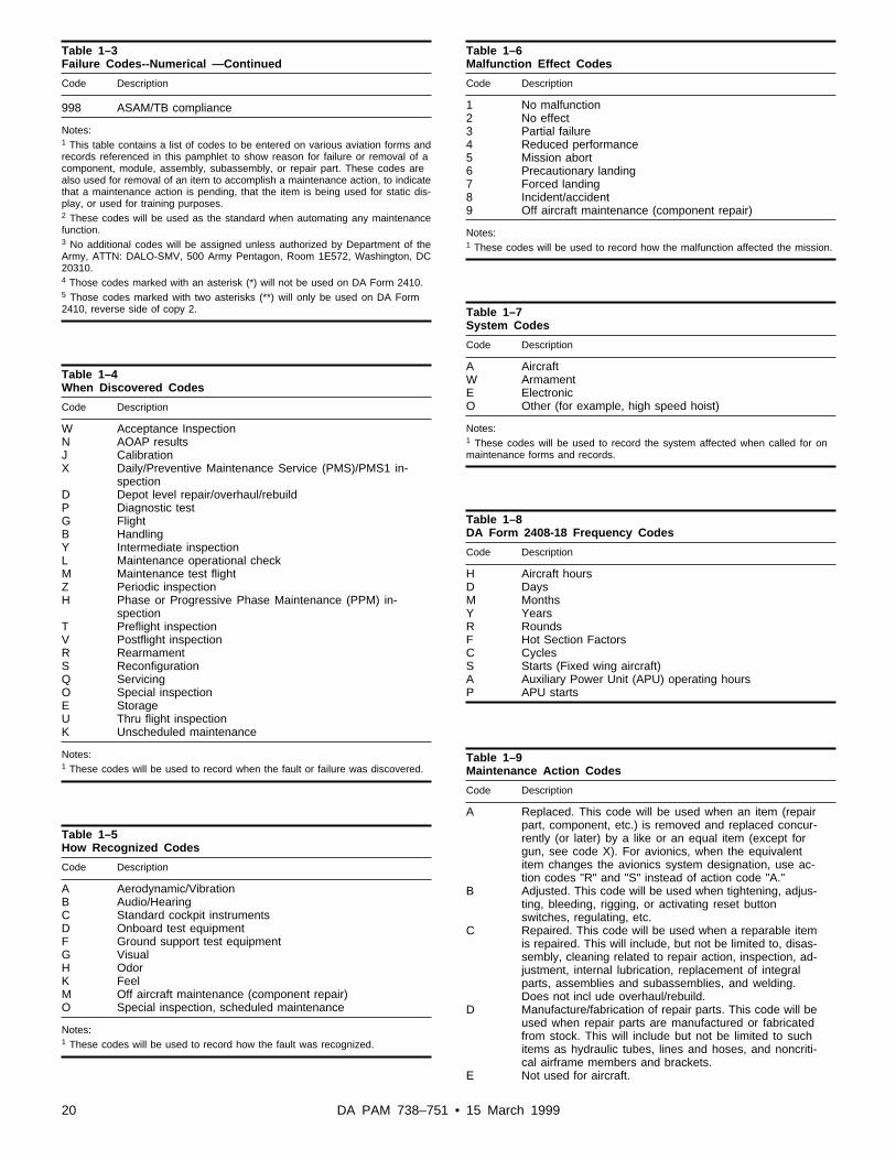
Table 1–3Failure Codes--Numerical —Continued
Code Description
998 ASAM/TB compliance
Notes:1 This table contains a list of codes to be entered on various aviation forms andrecords referenced in this pamphlet to show reason for failure or removal of acomponent, module, assembly, subassembly, or repair part. These codes arealso used for removal of an item to accomplish a maintenance action, to indicatethat a maintenance action is pending, that the item is being used for static dis-play, or used for training purposes.2 These codes will be used as the standard when automating any maintenancefunction.3 No additional codes will be assigned unless authorized by Department of theArmy, ATTN: DALO-SMV, 500 Army Pentagon, Room 1E572, Washington, DC20310.4 Those codes marked with an asterisk (*) will not be used on DA Form 2410.5 Those codes marked with two asterisks (**) will only be used on DA Form2410, reverse side of copy 2.
Table 1–4When Discovered Codes
Code Description
W Acceptance InspectionN AOAP resultsJ CalibrationX Daily/Preventive Maintenance Service (PMS)/PMS1 in-
spectionD Depot level repair/overhaul/rebuildP Diagnostic testG FlightB HandlingY Intermediate inspectionL Maintenance operational checkM Maintenance test flightZ Periodic inspectionH Phase or Progressive Phase Maintenance (PPM) in-
spectionT Preflight inspectionV Postflight inspectionR RearmamentS ReconfigurationQ ServicingO Special inspectionE StorageU Thru flight inspectionK Unscheduled maintenance
Notes:1 These codes will be used to record when the fault or failure was discovered.
Table 1–5How Recognized Codes
Code Description
A Aerodynamic/VibrationB Audio/HearingC Standard cockpit instrumentsD Onboard test equipmentF Ground support test equipmentG VisualH OdorK FeelM Off aircraft maintenance (component repair)O Special inspection, scheduled maintenance
Notes:1 These codes will be used to record how the fault was recognized.
Table 1–6Malfunction Effect Codes
Code Description
1 No malfunction2 No effect3 Partial failure4 Reduced performance5 Mission abort6 Precautionary landing7 Forced landing8 Incident/accident9 Off aircraft maintenance (component repair)
Notes:1 These codes will be used to record how the malfunction affected the mission.
Table 1–7System Codes
Code Description
A AircraftW ArmamentE ElectronicO Other (for example, high speed hoist)
Notes:1 These codes will be used to record the system affected when called for onmaintenance forms and records.
Table 1–8DA Form 2408-18 Frequency Codes
Code Description
H Aircraft hoursD DaysM MonthsY YearsR RoundsF Hot Section FactorsC CyclesS Starts (Fixed wing aircraft)A Auxiliary Power Unit (APU) operating hoursP APU starts
Table 1–9Maintenance Action Codes
Code Description
A Replaced. This code will be used when an item (repairpart, component, etc.) is removed and replaced concur-rently (or later) by a like or an equal item (except forgun, see code X). For avionics, when the equivalentitem changes the avionics system designation, use ac-tion codes "R" and "S" instead of action code "A."
B Adjusted. This code will be used when tightening, adjus-ting, bleeding, rigging, or activating reset buttonswitches, regulating, etc.
C Repaired. This code will be used when a reparable itemis repaired. This will include, but not be limited to, disas-sembly, cleaning related to repair action, inspection, ad-justment, internal lubrication, replacement of integralparts, assemblies and subassemblies, and welding.Does not incl ude overhaul/rebuild.
D Manufacture/fabrication of repair parts. This code will beused when repair parts are manufactured or fabricatedfrom stock. This will include but not be limited to suchitems as hydraulic tubes, lines and hoses, and noncriti-cal airframe members and brackets.
E Not used for aircraft.
20 DA PAM 738–751 • 15 March 1999

Table 1–9Maintenance Action Codes—Continued
Code Description
F Initial Inspection. This code will be used when inspectingitems to establish maintenance action(s) needed to re-turn item to serviceable status.
G Final Inspection. This code will be used when inspectingitems to determine acceptability of maintenance accom-plished.
H MWO. This code will be used to identify the applicationof MWOs.
I Corrosion removal/clean/wash.J Tested. This code will be used when performing diag-
nostic or mechanical tests that are used to measure theperformance of an item against established serviceabili-ty/technical standards.
K In process inspection.L Removed and Installed. This code will be used when an
item is removed for any reason and the same item isreinstalled.
M Checked NRTS. This code will be used when an item ischecked or tested and it is determined to be "Not Repa-rable at this station." Local policy may prescribe use ofNRTS codes in table 1-17.
N Checked Not Reparable. This code will be used whenan item is checked or tested and it is determined to benonreparable. This code applies also for items beyondeconomic repair limitations.
O Overhauled/Rebuilt/Remanufactured.P Checked Serviceable. This code will be used for items
checked or tested and no repair is required. This codeQMWO Removal. This code applies only if it is deter-mined that a reported fault does not exist or cannot beduplicated.
Q MWO Removal This code will be used to identify the re-moval of a MWO as a result of cancellation of the MWOrequirement.
R Removed. This code will be used when an item is re-moved and only the removal time is to be accounted for.
S Installed. This code will be used when an item is in-stalled and only the installation time is to be accountedfor.
T SOF/ASAM/TB SOU/TB Compliance. This code will beused to identify the compliance with the instructions of aspecifically cited SOF/ASAM/TB or SOU/TB.
U Decontamination.W Hour Meter Change. This code will be used to indicate
the replacement of an hour meter.X Gun Change. This code will be used to report the re-
placement of a gun.Y Special Mission Alteration (SMA), apply/applied.1 Servicing Scheduled (aircraft only). This code will be
used when servicing actions that include replenishmentor removal of consumable items used during flight oper-ations (such as fuel, oil, water, alcohol, hydraulic fluid,oxygen, air, nitrogen, ammunition, bombs, etc.) is ac-complished at intervals specified in maintenance manu-als and inspection checklists that apply.
2 Servicing unscheduled (aircraft only). This code will beused when servicing actions, which include replenish-ment or removal of consumable items used during flightoperations (such as fuel, oil, water, alcohol, hydraulicfluid, oxygen, air, nitrogen, ammunition, etc.), are ac-complished at unspecified intervals.
3 PMD, PMS or PMS1 (aircraft only). This code will beused to report accomplishment of the visual inspectionportion of the inspection. Other action codes will beused for related corrective actions as they apply.
4 Maintenance test flight/Maintenance operational check(aircraft only).
5 Preventive Maintenance. Periodic, phase or PPM (air-craft only). This code will be used to report accomplish-ment of the visual inspection portion of the inspection.Other action codes will be used for related corrective ac-tions as they apply.
Table 1–9Maintenance Action Codes—Continued
Code Description
6 Special Inspection (aircraft only). Use this code when aspecific action or inspection called for is not otherwisecovered. This code will be used for recording temporarystorage inspections. This code will be used for the visualinspection effort only. Other action codes will be usedfor related corrective actions as they apply. This codewill not be used instead of codes 3 or 5.
7 Ground Handling (aircraft only). Use this code forground support actions such as towing, jacking, parking,removal or installation of ground safety pins, mooring,etc.
8 Maintenance action not able to be performed (SAMSUnique)
9 Modification by replacement
Notes:1 These codes will be used to record maintenance actions taken on an itemwhen completing DA Form 2407 (Maintenance Request) and other maintenanceforms and records.
Table 1–10Functional Group Codes
Code Description
02 Airframe03 Landing gear04 Power plant installation05 Rotor system06 Drive system07 Hydraulics/Pneudraulics08 Instrument system09 Electrical installation10 Fuel system11 Flight control system12 Utility system13 Environmental control system14 Hoists and winches15 Auxiliary power plant16 Mission equipment17 Emergency equipment19 Avionics30 Armament sub system31 Fire control sub system32 Hellfire sub system33 TADS (Target Acquisition Designation Sight) assembly34 PNVS (Pilot Night Vision Sensor) assembly35 Area weapons system36 Other weapons systems37 Fire control/radar38 Symbol generation39 IHADSS (Integrated Helmet and Display Sighting Sys-
tem)52 Auto pilot system76 Electronics countermeasures80 Special tools82 Flyaway items83 Ground support items
Notes:1 These codes will be used to record the functional group of the aircraft and sub-systems, where the fault or maintenance action completed when called for onmaintenance forms and records.
Table 1–11Utilization Codes
Code Description
0 Active Components (except as otherwise listed)
21DA PAM 738–751 • 15 March 1999

Table 1–11Utilization Codes—Continued
Code Description
1 Depot Stock2 Post supply activities4 Operational readiness float (ORF)5 Installation maintenance and service equipment6 Customs Department/Border Patrol7 Army National Guard, except mobilization and training
equipment sites (Mates)8 Army National Guard (Mates)9 Air Force National Guard unitsA Army Reserve units, except equipment poolsB Army Reserve units, equipment poolsC Air Force ReserveD Army ROTCE Air Force ROTCG Defense Atomic Support AgencyH U.S. Army Intelligence and Security CommandJ Defense Communications Security AgencyK U.S. Army Training and Doctrine CommandL U.S. Army Test and Evaluation CommandM Civilian support unitsN Prepositioned stock in Europe, except Prepositioned
Materiel Configured to Unit Sets (POMCUS)P Depot installation equipmentQ Equipment assigned to service schools and training cen-
tersR Military Assistance Program (MAP)S Overhaul facility, militaryT Overhaul facility, commercialU Manufacturing facilityX Repair Cycle Float (RCF)Y POMCUS in Europe
Table 1–12Time Conversion Codes
Minutes Parts of hour
0 0.01-6 0.17-12 0.213-18 0.319-24 0.425-30 0.531-36 0.637-42 0.743-48 0.849-54 0.955-60 1.0
Notes:1 Time called for in manhour, flight hour, component operating hours, etc. blocksof DA Forms contained in this document will be reported in hours and tenths ofhours. When entering hours or tenths of hours on forms a zero should beentered on either side of the decimal; for example, 2.0 when entering full hoursor 0.7 when entering tenths of hours.
Table 1–13Equipment Loss Codes
Code Description
D Loss through mutilation, ie, cutting, crushing, melting,burning, alteration, etc., to prevent reuse for original in-tended purpose.
E Loss due to disassembly of a reportable integrated setassembly.
F Component/module or repair part formerly designatedby TB 1-1500-341-01 as a tracked item that no longerrequires tracking using DA Form 2410. Combat loss(abandoned, captured, or destroyed).
Table 1–13Equipment Loss Codes—Continued
Code Description
I Combat loss (abandoned, captured, or destroyed).J Turned in to Defense Reutilization and Marketing Office
or salvage point.K Shipped to other (non-Army) Government, departments,
agencies, services, foreign military sales or Security/MAP countries.
L Physical loss other than combat (pilferage, theft, etc.)M Identification loss, e.g., NSN, P/N or serial number
redesignation (change) resulting from a conversion ormodification through an approved MWO, DMWR, en-gineering change or process, to include redesignationsnot involving maintenance.
N Identification loss, integrated into a set assembly or sys-tem; or a change of equipment serial number or regis-tration number.
V Used for static displays and museums within the Army.When no longer used in this capacity, item is to be proc-essed according to TM 1-1500-328-23.
W Used for static displays and museums located outsidethe Army.
X Used for training purposes on a maintenance trainingairframe (MTA), as a Dynamic Training Device, or Iso-lated Aeronautical Element. Time Between Overhaul(TBO) components/modules must be overhauled andRC or CC items must be inspected at a depot facilitybefore being used on flyable aircraft (See TM 1-1500-328-23).
Table 1–14Equipment Gain Codes
Code Description
A Gain of new item to U.S. Army inventory. Limited togains from new procurement/manufacture. Includes newmanufactured items with a later NSN or P/N on items al-ready listed in TB 1-1500-341-01.
C Gain of items from static displays, museums, or trainingaircraft (See TM 1-1500-328-23).
F Gain of an individual reportable item as a result of disas-sembly of an integrated set/assembly.
Q Reclaimed from DRMO or cannibalization point.P Combat gain (recaptured or recovered)R Received from other (non-Army) governments, depart-
ments, agencies, services or Security/MAP countries.S Identification gain, e.g., NSN, PN or serial number
redesignated (change) resulting through an approvedMWO, engineering change or process, to includeredesignations not involving maintenance.
T Identification gain, integrated set assembly with newNSN; or a change of equipment serial number or regis-tration number
U To show the first DA Form 2410 reporting on items be-ing added to TB 1-1500-341-01 by message or by publi-cation revision or to show the first DA Form 2410 reporton a used item requiring reporting that was neverpreviously reported. Does not include items being manu-factured with the same or later NSN or P/N and not yetinducted into the Army inventory. These items will reflectan "A" gain code when accepted.
22 DA PAM 738–751 • 15 March 1999

Table 1–15Not Reparable This Station Codes (NRTS)
Code Description
1 Bench Checked-NRTS (Not Reparable This Station),Repair Not Authorized. This code will be entered whenthe shop is not authorized to accomplish the repair. Thiscode will not be used unless the repair of the item isspecifically prohibited by current technical directives.
2 Bench Check-NRTS-Lack of Equipment, Tools, or Facili-ties. This code will be entered when repair cannot beaccomplished due to lack of equipment, tools, or facili-ties. Lack of authorization for the required tools, equip-ment, or facilities does not preclude use of this code.
3 Bench Check-NRTS-Lack of Technical Skills. This codewill be entered when repair cannot be accomplished dueto lack of technically qualified people.
4 Bench Check-NRTS-Lack of parts. This code will beentered when parts are not available to accomplishrepair.
5 Bench Check-NRTS-Shop Backlog. This code will beentered when repair cannot be accomplished due to ex-cessive shop backlog.
6 Bench Check-NRTS-Lack of Technical Data. This codewill be entered when repair cannot be accomplished dueto lack of maintenance manuals, drawings, etc., whichdescribe detailed repair procedures and requirements.
7 Bench Check-NRTS-Excess to Base Requirements.This code will be entered when repair will not be sched-uled for shop repair due to item being excess to baserequirements.
8 This code not used.9 Bench Check-Condemned. This code will be entered
when the item cannot be repaired and is to be proc-essed for condemnation, reclamation or salvage. Thiscode will also be used when a "condemned" condition isdiscovered during support maintenance disassembly orrepair.
Table 1–16Type Maintenance Request Code (Type MNT Req CD) or Repair
Code Description
1 Return to user. Maintenance actions need to be per-formed and the equipment returned to the user.
2 Modification Normal. A modification, special purpose al-teration or special mission alteration is required to beapplied on an item of equipment.
3 Modification Urgent/Limited. An urgent or limited urgentmodification or safety recall ordered is required to beapplied on an item of equipment.
6 Cosmetic Maintenance. Indicates fuselage and other air-craft surface work, painting, etc.
7 Sample Data Collection. Data provided by user in re-sponse to query by support maintenance.
8 Usage Device Change. Data recorded by customer unitto support unit upon change of a usage-recording device(rounds, hours).
9 Production. A work request that applies to more thanone item, usually controlled by a maintenance controlnumber, when a production-line type of operation maybe applied.
A Estimated Cost of Damages. A request for inspection toidentify cost of repairs of a specific damage, as in an ac-cident.
C Classification. A request for the performance of an in-spection to determine the classification code for turn into the supply system.
D Reparable Exchange. A request for the repair of items insupport of a Reparable Exchange (RX) program
F Return to Stock. A work request indicating periodicmaintenance is needed.
H Recall Maintenance. Actions that can be identified andscheduled in advance.
Table 1–16Type Maintenance Request Code (Type MNT Req CD) orRepair—Continued
Code Description
J Component Change. Data recorded by a customer unitupon change.
K Oil-Analysis Recommendation. The maintenance re-quest is being generated as the result of an oil-analysislaboratory recommendation.
Notes:1 These codes are used to describe the maintenance action requested. Thesecodes are applicable to DA Form 2407. (SAMS unique.)
Table 1–17Work Request Status Codes (STA)
Code Description
A Awaiting initial inspection. Includes initial inspection, ac-ceptance, and parts determination.
B* In Shop.C* Awaiting Shop. The initial and acceptance inspections
have been completed and parts are on hand.D Deferred. Equipment in use, awaiting scheduled mainte-
nance (may or may not be awaiting parts) and not con-sidered high priority in that equipment is operating butrequires some maintenance or modification.
E Awaiting Final Inspection.F Final Inspection Complete. Includes final inspection and
work order/log book completion.H Awaiting Disposition. Awaiting disposition instructions
from a higher source.I* Awaiting Shop while Awaiting Parts. Cannot be used if
the item is Not Mission Capable (NMC) reportable.J* In Shop Awaiting Parts, Work Continues. When this
code is used, the calculation for NMCS/NMCM willremain in NMCM. This code was designed for aircraftbut may be used for other items requiring maintenance.
K Awaiting Parts (Not NMCS). No further repair actionscan be made because parts are not available in shopsupply.
M* Evacuated for Repair and Return. All items on the workrequest were evacuated to another maintenance activityfor repair and return.
N Item Checked and Found Serviceable. This code ap-plies only if the reported fault does not exist, or can notbe duplicated.
O* Awaiting Evacuation.P Deadline Other Reasons. Grounded or dead lined for
lack of facility, tools, test equipment or the completion ofintra-shopwork request.
Q Awaiting Estimated Cost of Damage (ECOD) Actions.Items awaiting release of quality control officer beforerepairs can be started.
R Awaiting Pickup. Item has been repaired or appropriateaction taken. Owning unit has been notified and item isa waiting pickup. Before code "R" can be used, the workrequest MUST be closed, using a code "S" through "Z"(minus code "U.") If item is inoperative, "R" stops sup-port NMC time. NMC time is charged to the owning unituntil it submits a code "U."
S Closed. Completed this Maintenance Activity. Repairshave been completed by the support activity receivingthe end item or component. Work request is closed.
T Closed, Completed by Other Maintenance Activity.Repairs have been completed and returned by the evac-uated activity to the support activity. Work request isclosed.
23DA PAM 738–751 • 15 March 1999

Table 1–17Work Request Status Codes (STA)—Continued
Code Description
U Picked Up (must be closed first).
a. At Unit Level-Closed the ORG WON. All related re-cords on the Inoperative Equipment File will be closed.All inoperative time stops.
b. At AVIM level--Picked up by customer. The supportwork order number and all related direct support workorders will be deleted from SAMS-1 during the nextweekly process.
V Closed for Reason of Exchange (Float). Repairs havenot been completed, however; work request closed byreason of exchange (maintenance float).
W Closed. Nonreturnable. Work request closed by turn inof an item classified as uneconomically reparable ornonreparable (classification).
X Closed. Exceeds MEL. Work request closed as exceed-ing time limits or maintenance capability (classificationexample: code F).
Y Closed. Nonacceptable for Standards (Rejected). Workrequest is closed. It did not meet acceptable standards.
Z Closed. Without Completion. Work request closed orcancelled without completion (example: initial inspectionwas not started).
1* Awaiting NMC parts. No further repairs can be made be-cause of lack of parts in shop supply. This code is onlyused for NMC reportable items.
7 Awaiting Float Transaction.8 Rework Return to Shop. If work request is "U," code 8
must be used before job is returned to working status.9 Begin Intransit Time.
Notes:1 These codes indicate the status of an individual work request as it progressesthrough maintenance shops. These codes are applicable to all SAMS forms hav-ing a "STA" block. (SAMS Unique)2 Above status codes followed by an asterisk "*" can be used at the unit level.
Table 1–18Part Source Code
Code Description
X CONTROLLED EXCHANGE. This code will be used toindicate source data for controlled exchanged repairparts when completing DA Form 2407.
Table 1–19The Metric System and Equivalents
Symbol When you know Multiply To find Symbolby
Lengthin inches 2.54 centimeters cmft feet 30.0 centimeters cmyd yards 0.9 meters mmi miles 1.6 kilometers kmmm millimeters 0.04 inches incm centimeters 0.4 inches inm meters 3.3 feet ftm meters 1.1 yards ydkm kilometers 0.62 miles mi
Areain2 square inches 6.5 square cm2
centimetersft2 square feet 0.09 square meters m2
yd2 square yards 0.8 square meters m2
Table 1–19The Metric System and Equivalents—Continued
Symbol When you know Multiply To find Symbolby
mi2 square miles 2.6 square km2
kilometersacres 0.4 hectares ha
cm2 square 0.16 square inches in2
centimetersm2 square meters 1.2 square yards yd2
km2 square 0.4 square miles mi2
kilometersha hectares 2.5 acres
(10,000 M2)
Mass (weight)oz ounces 28 grams glb pounds 0.45 kilograms kg
short tons (2000 0.9 ton tlb.)
g grams 0.035 ounces ozkg kilograms 2.2 pounds lbt ton (1000 kg) 1.1 short tons
Volumetsp teaspoons 5 milliliters mlTbsp tablespoons 15 milliliters mlfl oz fluid ounces 30 milliliters mlc cups 0.24 liters lpt pints 0.47 liters lqt quarts 0.95 liters lgal gallons 3.8 liters lft3 cubic feet 0.03 cubic meters m3
yd3 cubic yards 0.76 cubic meters m3
ml milliliters 0.03 fluid ounces fl ozl liters 2.1 pints ptl liters 1.06 quarts qtl liters 0.26 gallons galm3 cubic meters 35 cubic feet ft3
m3 cubic meters 1.3 cubic yards yd3
Temperature (exact)°F Fahrenheit 5/9 (af- Celsius °C
temperature ter temperaturesubtrac-ting32°)
°C Celsius 9/5 Fahrenheit °Ftemperature (then temperature
add32°)
Table 1–20Aircraft Transfer Decision Table
TRANSFER TO RECORDS TO REMOVE COPIES TO(NOTE 6) AMCOM DATAPLATE AMCOM (NOTE
1)
Federal, No Flyable A/C YesState, NoCounty, or Non-flyableLocal Government A/C (NOTE 7)FMS or MAP No No YesDestroyed Aircraft Yes Yes NoTransferred to No (NOTE 7) YesDRMO excess ordeteriorated aircraft(NOTE 2)Static Display Yes Yes NoMuseum within (NOTE 3) (NOTE 7) (NOTE 3)Army
24 DA PAM 738–751 • 15 March 1999

Table 1–20Aircraft Transfer Decision Table—Continued
TRANSFER TO RECORDS TO REMOVE COPIES TO(NOTE 6) AMCOM DATAPLATE AMCOM (NOTE
1)
Museum outside (NOTE 3) (NOTE 7) (NOTE 3)ArmyDavis Monthan No No YesExcess aircraft No No Yessold to private sec-torCategory A trainer No No YesCategory B trainer No No YesMaintenance Train- No No Yesing Airframe (MTA)often referred to asCategory C trainerLocal Salvage (NOTE 4) Yes NoLocal Salvage for (NOTE 5) Yes Yestraining
Notes:1 Send a copy of the current DA Form 2408-13, last page of aircraft DA Form2408-15 (to include the close-out statement), and copies of all DA Forms 2408-16 and 2408-16-1.2 Forward dataplate and all records for AH-1, AH-64, OV-1, and RV-1 toAMCOM.3 If the aircraft has significant historical value and/or the records are needed aspart of the display the records may remain with the aircraft. If the records remainwith the aircraft, comply with NOTE 1.4 Forward dataplate and a copy of aircraft disposition instructions to AMCOM.Forward the records to AMCOM upon completion of salvage.5 Forward dataplate and a copy of aircraft disposition instructions to AMCOM.Forward the records to AMCOM after all needed parts are removed from the air-craft. Parts will not be removed from the aircraft after the records are transferredto AMCOM.6 DA Form(s) 2410 will be completed for all items removed or installed beforetransfer or completion of local salvage and DA Form 2408-16 and/or 2408-16-1will be updated. A closing statement will be made on the DA Form 2408-15 stat-ing disposition of the aircraft, date of transfer, or other action (such as local sal-vage), current aircraft hours, current history recorder readings for both engines(H-60 and AH-64), unit transferring the aircraft, disposition of the aircraftdataplate, and POCs phone number.7 Remove the data plate and make a photocopy of the data plate. Photocopy willremain with the aircraft. Data plate will be forwarded to AMCOM.
Chapter 2Aircraft Logbook Forms and Records
2–1. General-aircraft logbook forms and recordsa. This chapter instructs in the use, general and special instruc-
tions, disposition, and how to fill out logbook forms and records foraircraft, aircraft training devices or simulators, and installed avia-tion-related mission equipment.
b. Aircraft logbook forms and records will be kept by all aviationunits, organizations, and/or activities that operate, fly, and maintainaircraft and aviation-related mission equipment. These records areused to control operations of aircraft, aircraft training devices orsimulators, maintenance trainer airframes, and installed aviation-related mission equipment. See appendix D for a list of forms andrecords to be maintained.
c. A “zero time closeout” may be completed at the discretion ofthe maintenance officer, but will be performed after completion ofextensive maintenance, or a periodic/phase maintenance inspectionrequiring a general test flight. The closeout will be completed beforethe test flight. See subparagraph 2–9c(1)(e) and 2–10c(9)(b). A“zero time closeout” will be performed by ULLS-A and LAS userswhen the aircraft has not flown and a new Flight Pack has beengenerated.
d. When the aircraft is operated away from its home station, the
closed out forms will stay in the logbook until the aircraft returns.During extended time away from the home station, the aircraftforms will be removed and filed in the local maintenance office.The forms will be delivered back to the home station upon comple-tion of the exercise, TDY, or combat.
e. A 6-month file of logbook forms will be kept. The monthlyfile will start on the 16th of each month and end on the 15th of thefollowing month. As each new month is added, the seventh monthmay be destroyed. If the aircraft does not fly in a given month, thefile will be kept intact until the aircraft flies again. Always keep 6flying months, plus the current month.
f. Authorized units with ADPE support can use automated orelectronically produced forms as prescribed in subparagraph 1–6f.
2–2. Logbook Binder (NSN 7510–00–889–3494 (2 1/2 inch))a. The logbook binder (fig 2–1) will be used to hold the DA
forms listed in subparagraph 1–15c for the specific type aircraft orequipment.
b. The logbook binder has a plastic slot on the outside to hold theDA Form 2408–31, identifying the aircraft or other equipment towhich the logbook belongs.
c. The logbook will remain with the aircraft or other aviatione q u i p m e n t w h e n i t i s o p e r a t e d o r f l o w n , i n s p e c t e d , s e r v i c e d ,repaired, overhauled, modified, TDY, or on loan. Logbooks mayremain with the aircraft when transferred (see para 1–16).
d. The Equipment Record Folder, NSN 7510–01–065–0166, willbe used for aviation NVG historical records and may be used forother aviation associated equipment listed in appendix D.
2–3. DA Form 2408, Equipment Log Assemblya. Purpose of the DA Form 2408 (fig 2–2). This form provides a
reference for operational, mission, duty, flight condition symbols,aircraft condition status symbols, and maintenance codes to be usedo n D A F o r m s 2 4 0 8 – 1 2 , 2 4 0 8 – 1 3 , 2 4 0 8 – 1 3 – 1 , 2 4 0 8 – 1 3 – 2 ,2408–13–3, and other related maintenance forms.Note. Flying duty, mission, and flight condition symbols are also listed inAR 95–1.
b. Use. Provide information to assist air crew and maintenancepersonnel on filling out logbook, maintenance, and historical forms,records, and files. If a conflict exists between AR 95–1 and thispamphlet, the information in AR 95–1 takes precedence.
c. Disposition. This form is a permanent part of the logbook.When it gets soiled or damaged replace it with a new one.
2–4. DA Form 2408–31, Aircraft Identification Carda. Purpose of the DA Form 2408–31 (fig 2–3). This form iden-
tifies a specific aircraft logbook to an aircraft, aircraft training de-vice or simulator, or other aviation equipment.
b. Use. A DA Form 2408–31 goes in the outside front plastic slotof each aircraft logbook, containing operational and maintenanceforms and records to show:
(1) The MDS of aircraft or other equipment.(2) Serial number of aircraft or other equipment.(3) Unit or organization to which the aircraft or equipment is
assigned.(4) Name of the crew chief or mechanic assigned to the aircraft
or person responsible for maintenance of other equipment.(5) Name of the supervisor that is responsible for the aircraft or
other equipment.c. Disposition. This form is a permanent part of the logbook. A
new card will be made out when the information, on the card,changes or the card is no longer readable. When a new card is madeout the old card will be thrown away.
2–5. DA Form 2408–4–1, Weapon Record Dataa . P u r p o s e o f t h e D A F o r m 2 4 0 8 – 4 – 1 ( f i g 2 – 4 ) . T h i s f o r m
provides a record of rounds fired, maintenance actions, and compo-nent replacement during the service life of the armament systemsinstalled on the aircraft. This information is important for crew andaircraft safety.
b. Use. The DA Form 2408–4–1 is used to—
25DA PAM 738–751 • 15 March 1999

(1) Record rounds fired for each armament subsystem that re-quire service or replacement after a specific number of rounds fired.
(2) Used for maintenance including replacement, overhaul, orrebuild of components/modules. The applicable armament TM listscomponents inspected or replaced on a rounds-fired basis.
c. General instructions.(1) Appendix D lists aircraft requiring this form. It will be main-
tained only if the aircraft is equipped with an armament system.(2) The pilot, crew chief, armament mechanic, or maintenance
supervisor will make entries in the weapons data block(s), afterf i r i n g t h e w e a p o n o r p e r f o r m i n g m a i n t e n a n c e . A n y a d d i t i o n a lremarks considered significant to the operation and/or maintenanceof the weapon system will be entered by the armament equipmentuser or support activity.
(3) One DA Form 2408–4–1 will be used for each weapon in-stalled on the aircraft, regardless of the number of barrels perweapon.
d. Disposition.(1) Keep the current DA Form 2408–4–1 in the aircraft logbook.
When the armament weapon system is removed from aircraft and isto be evacuated or stored (unmounted), remove the form from thelogbook and attach to the weapon in a protective cover.
(2) When the form is completely filled, start a new DA Form2408–4–1 with all needed information “brought forward” to the newform. The person that “brought forward” the entries will enter his orher PID on the form. Retain the old form in the maintenance officefile for 90 days, then destroy it.
(3) When armament equipment is overhauled or rebuilt, destroythe DA Form 2408–4–1 and make a new form with zero roundsfired.
2–6. DA Form 2408–4–2, Weapon Sighting Data (OH-58D)a. Purpose of the DA Form 2408–4–2 (fig 2–5). This form is
used to record data constants and other weapon sighting informationf o r t h e m a s t m o u n t e d s i g h t ( M M S ) i n s t a l l e d o n t h e O H - 5 8 Dhelicopter.
b . U s e . T h i s f o r m i s u s e d f o r O H - 5 8 D h e l i c o p t e r s f o r t h efollowing:
(1) To provide the pilot, crewmember, and armament mainte-nance personnel a ready reference of computer data for properoperation of the MMS.
(2) To show the removal and replacement of component parts ofthe MMS system. When one or more of the MMS components listedon the form is removed and replaced with a different component theform will be updated with the new component data constant(s).
(3) As a ready reference of data constants and other sightinginformation during flight and maintenance operations.
c. General. A second copy of this form may be kept in theaircraft historical file. If a backup copy is kept, anytime an entry ismade on the logbook copy, the same entry will be made on thebackup copy in the historical file. The backup form kept in thehistorical file would provide data constants for reconstruction of anew form if the logbook copy becomes lost.
d. Disposition.(1) When the MMS turret assembly is removed from the aircraft,
for any reason, the DA Form 2408–4–2 will be removed from thelogbook. The form will be placed in a protective envelope andattached to the MMS turret assembly. A new DA Form 2408–4–2will be made out for the new MMS turret assembly installed on theaircraft and placed in the logbook.
(2) Keep the DA Form 2408–4–2 in the aircraft logbook until itbecomes damaged, entries become obliterated, or all the lines inblocks 5, 8, and 9 are used and another entry is needed. Then makeout a new form, per paragraph 1–7, and throw the damaged or filledout form away.
2–7. DA Form 2408–4–3, Weapon Sighting Data (AH-64A)a. Purpose of the DA Form 2408–4–3 (fig 2–6). This form is
used to record bore sight harmonization computer data and other
weapon sighting information for armament sub system assembliesinstalled on AH-64A helicopters.
b . U s e T h i s f o r m i s u s e d f o r A H - 6 4 A h e l i c o p t e r s f o r t h efollowing:
(1) To provide the pilot, crewmember, and armament mainte-nance personnel a ready reference of fire control computers (FCC)data for proper operation of armament systems.
(2) To show removal and replacement of FCC and air data proc-essors. When the FCC or Air Data Processor, listed on the form, isremoved and replaced with a different component update the formwith the new components bore sight harmonization computer data.
(3) As a ready reference of data constants and other sightinginformation during flight and maintenance operations.
c. General. A second copy of this form may be kept in theaircraft historical file. If a backup copy is kept, anytime an entry ismade on the logbook copy, the same entry will be made on theback-up copy in the historical file. The back-up form kept in thehistorical file would provide data constants for reconstruction of anew form if the logbook copy becomes lost.
d. Disposition. Keep the DA Form 2408–4–3 in the aircraft log-book until it becomes damaged, entries become obliterated, or allthe lines in blocks 5 through 8 are filled and another entry isneeded. Then make out a new form, per paragraph 1–7, and throwthe damaged or filled up form away.
2–8. DA Form 2408–12, Army Aviator’s Flight Recorda . P u r p o s e o f t h e D A F o r m 2 4 0 8 – 1 2 ( f i g 2 – 7 ) . T h i s f o r m
p r o v i d e s a r e c o r d o f f l i g h t o p e r a t i o n s a n d s o m e m a i n t e n a n c einformation.
b. Use. This form is used for aircraft and aircraft training de-vices/simulators, listed in appendix D, to record:
(1) Air crew personnel data, aircraft flying time, duty, and typeof flight done by the pilot and crew.
(2) HIT check deviations for installed engines.(3) Operating hours and number of starts for designated APUs.(4) Rounds fired.(5) Landing gear cycles for aircraft with retractable landing gear,
when required.(6) Internal and external loads.(7) Servicing data for aircraft and APU.(8) Hot section factor (HSF) counts for the T703 engine installed
on OH-58D helicopters.Note. Record the operating hours/starts/hour meter readings for APUs whenrequired by the applicable TM-23 maintenance manual or if requested byunit or activity commander. Use only hard copies of DA Form 2408–12, DONOT USE ULLS-A generated form except in an emergency (does not gener-ate the backside).
c. General.(1) The crew chief or mechanic assigned to the aircraft will:(a) Make sure that enough copies of DA Form 2408–12 are in
the aircraft logbook to complete the assigned mission.(b) Closeout the DA Form 2408–12 after the last flight of the
mission day or before the first flight of the next mission day.( c ) U L L S - A u s e r ’ s w i l l e n t e r a l l d a t a f r o m t h e D A F o r m
2408–12 into the ULLS-A data base after the last flight of themission day.
(d) Prepare a new DA Form 2408–12 after the last flight of themission day or before the first flight of the next mission day.
(e) Before each flight check quantity of fuel and oil in tanks,anti-icing fluid level, and make sure the oxygen system pressuremeets the TM requirement. Record actual levels on the first line inblock 7, SERVICING DATA, before the first flight of the missionday.Note. For helicopter flights, this check will include the Helicopter OxygenSystem (HOS) when installed.
(2) The pilot of the aircraft will make sure that the DA Form2408–12 is properly filled out. This data is very important; it is usedin a permanent historical record for pilots/crewmembers to showflying hours, types of missions flown, flight conditions, and payp u r p o s e s f o r f l y i n g d u t i e s p e r f o r m e d . T h e p i l o t m u s t e n t e r a l l
26 DA PAM 738–751 • 15 March 1999

needed flight information for all crewmembers that were on theflight. The pilot will also enter operational data, such as landings,touchdown autorotations, engine starts, loads, cycles operated, hotsection factor readings, rounds fired, and so forth. Upon landingafter each flight, the pilot will read the engine monitor page dis-played on the multifunction display (MFD) for HSF counts andenter the counts in block 6a, HSF, of the DA Form 2408–12.
(3) When an individual on flight status has performed flyingduties in an aircraft not assigned to his or her unit or activity, acopy of the DA Form 2408–12 will be provided to that individual.The pilot in command of the flight will annotate the margin of theDA Form 2408–12 with a remark, “I certify that this is a true copyof the DA Form 2408–12,” and the date (dd mmm yy) of the flight.The signature of the pilot in command, and the date will be enteredfollowing the certification.
(4) A flight or series of flights, that take off before 2400 hoursand lands after 2400 hours is credited to the date of takeoff. Enterthe time it took for the flight in hours and tenths of an hour in theFlight Hour block. See DA Form 2408, Time Conversion Table, inthe logbook or table 1–12 at the end of chapter 1.
(5) If more than one DA Form 2408–12 is used for the missionday, enter the totals in block 8 on the last page.
d. Disposition(1) After the last flight of the mission day or before the first
flight of the next mission day, closeout the DA Form 2408–12, bytotaling the flight hours, landings, touchdown autorotations, APUstarts, APU hours, hour meter hours, engine starts, landing gearcycles, and rounds fired in block 8. Enter these totals on the DAForm 2408–13 in the blocks that apply. Make out a new DA Form2408–12. Remove the closed out DA Form 2408–12 from the air-craft logbook and send the closed out form through the maintenanceoffice to the operations office. When the aircraft is operated awayfrom its’ home station, the closed out forms will stay in the logbookuntil the aircraft returns.
(2) Operations will keep the DA Form 2408–12 for 3 months,then destroy it.
2–9. DA Form 2408–13, Aircraft Status Information Recorda . P u r p o s e o f t h e D A F o r m 2 4 0 8 – 1 3 ( f i g 2 – 8 ) . T h i s f o r m
provides a record of aircraft and aviation associated equipment con-dition status and other aircraft maintenance information.
b. Use. This form is used for aircraft and aircraft training devicesor simulators listed in appendix D for the following.
(1) To show the present status of the aircraft, aircraft trainingdevices/simulators, maintenance trainer airframes, and mission re-lated equipment aboard the aircraft.
(2) To show current hours, hours flown today, and total aircrafthours.
(3) To show number of landings and touchdown autorotationsduring the report period.
(4) To show current HSF counts readings today for the T703engine installed in OH-58D helicopters.
(5) To sign off daily inspections.(6) As a ready reference of the last 5 HIT checks when ULLS-A
is implemented.(7) To show when the next scheduled maintenance inspection,
such as when the next phase inspection is due.(8) To show operational hours and starts for the APU.(9) To show the number of engine starts for multiengine fixed
wing aircraft.c. Special instructions.(1) The crew chief or mechanic—(a) Makes out a new DA Form 2408–13 after the last flight of
the mission day or before the first flight of the next mission day.Note. On maintenance trainer airframes, make out a new DA Form 2408–13after each major maintenance action.
(b) Perform a daily inspection or PMS when due, using the mostcurrent PMD or PMS CL for the type and model aircraft assigned.E n t e r a l l f a u l t s f o u n d d u r i n g t h e i n s p e c t i o n o n D A F o r m2408–13–1.
(c) Enter the correct status symbol for the aircraft and the avia-tion mission related equipment in block 10, SYSTEM STATUSblock. There are fourteen spaces for system status symbols fora i r c r a f t o r a i r c r a f t t r a i n i n g d e v i c e s / f l i g h t s i m u l a t o r s , a n d s e v e nspaces for installed mission related equipment for use during themission day. If more spaces are needed during a mission day, start anew DA Form 2408–13.
(d) Closeout the DA Form 2408–13 after the last flight of them i s s i o n d a y , b y e n t e r i n g t h e f l i g h t t i m e , l a n d i n g s , t o u c h d o w nautorotations, and other required information in the TODAY blocks.Add these to the CURRENT blocks, and put results in TOTALblocks. Enter the HSF counts for the T703 engines from DA Form2408–12, block 8, in the TOTAL block. When using the manualmethod of recordkeeping, make out a new DA Form 2408–13 andmake sure the current data is correct. For units using ULLS-A, thenew DA Form 2408–13 will be printed when the Flight Pack isgenerated by the ULLS-A program.
(e) When performing a “zero time closeout” enter “0” in theT O D A Y b l o c k s f o r c u r r e n t a i r c r a f t h o u r s , l a n d i n g s , t o u c h d o w nautorotations, and other blocks that apply. Enter the total in theTOTAL blocks. When using the manual method of recordkeeping,make out a new DA Form 2408–13 and make sure the current datais correct. For units using ULLS-A, the new DA Form 2408–13 willbe printed when the Flight Pack is generated by the ULLS-A pro-gram. A “zero time closeout” will be performed by ULLS-A user’swhen the aircraft has not flown for a while and a new Flight Packhas been generated by the ULLS-A program without the aircraftbeing flown.
(2) The pilot—(a) Checks the aircraft and installed aviation associated equip-
ment condition status shown in the SYSTEM STATUS blocks. TheSYSTEM STATUS block must show the condition status of themost serious uncorrected fault on the DA Form 2408–13–1, DAF o r m 2 4 0 8 – 1 3 – 2 , D A F o r m 2 4 0 8 – 1 3 – 3 , o r t h e D A F o r m2408–14–1.
(b) Checks the DA Form 2408–18 to see if any inspections,services, or replacements are due or overdue.
(c) Checks that fuel, oil, oxygen, and anti-icing tanks are serv-iced to be sure sufficient amounts remain to complete the assignedmission.
( d ) P e r f o r m s a p r e f l i g h t c h e c k / i n s p e c t i o n , p e r T M - 1 0 C L , a n denters all faults/remarks found on DA Form 2408–13–1.
(e) Enters the date (dd mmm yy), in the DATE block, of the firstflight of the mission day, if the aircraft is safe to fly and can do theassigned mission.
(f) Performs a thru flight check/inspection per TM-10CL, afterlanding at any intermediate stop, and enters all faults/remarks onDA Form 2408–13–1.
(g) Performs a post flight check/inspection per TM-10CL, afterthe last flight of the mission day, and enters all faults/remarks onthe DA Form 2408–13–1.
(3) After extensive maintenance or inspection that requires a testflight, the closed out forms will remain available (preferably in theunit maintenance or quality control office) for the flight or mainte-nance crew until the test flight is signed off.
(4) DA Forms 2408–13 received in the maintenance office willbe checked against the previous DA Form 2408–13 to make surethat aircraft time, status, and other entries are correct.
(5) A DA Form 2408–13 showing current aircraft status will stayi n t h e l o g b o o k o f a i r c r a f t i n a d m i n i s t r a t i v e s t o r a g e . A F o r m2408–13, block 10, SYSTEM STATUS, must reflect the currentcondition status symbol for the most serious uncorrected fault/defi-ciency; unapplied directives, such as SOF messages, ASAMs, TBs,MWOs; component/module, accessories, or other items due or over-due replacement; or scheduled and special inspections due or over-due completion recorded on the current aircraft logbook forms.
(6) When the engine on a OH-58D helicopter is removed forreplacement, the total HSF counts recorded in block 11, will beentered on the engine DA Form 2408–16, block 7, for example, “21JAN 92, HSF counts is 1432, B. Brand, 53rd AVN CO, FortLeavenworth, KS.”
27DA PAM 738–751 • 15 March 1999

d. Disposition.(1) The closed out DA Form 2408–13 will be removed from the
logbook at the end of the mission day or before the first flight of thenext day, or after a “zero time closeout” is performed. The closedout form will be attached to the Flight Pack and sent to the unitmaintenance office.
(2) The DA Forms 2408–13 will be filed in the 6-month file anddisposed of per the instructions for the 6-month file.
2–10. DA Form 2408–13–1, Aircraft Inspection andMaintenance Record
a. Purpose of the DA Form 2408–13–1. This form has five majorpurposes (see fig 2–9). It provides a place to record aircraft andaviation associated equipment—
(1) Operational remarks and/or faults found during flight or oper-ation, preflight, through flight, and post flight inspections.
(2) Checks, services, scheduled or unscheduled maintenance in-s p e c t i o n s , M W O ’ s , S O F m e s s a g e s / A S A M s / T B s c o m p l e t e d o runapplied.
(3) Faults found including battle damage assessment and repair(BDAR): when faults were found, when faults occurred, how faultswere recognized, effect faults had on the operation or mission, andcorrective actions taken to correct faults.
( 4 ) M a n h o u r s ( m a n p o w e r r e q u i r e m e n t c r i t e r i a ( M A R C ) , A R570–2) it takes to do maintenance and quality control work, bymilitary, civilian, and contract maintenance support personnel.
( 5 ) C o n d i t i o n s t a t u s s y m b o l s f o r a i r c r a f t , a v i a t i o n a s s o c i a t e de q u i p m e n t , i n c l u d i n g m i s s i o n r e l a t e d e q u i p m e n t a b o a r d a i r c r a f t .Used to update the AMASS portion of the ULLS-A program.
b. Use. DA Form 2408–13–1 is used by the aircraft crew chief,mechanic assigned, pilot, maintenance and quality control personnel,the unit commander and his or her designated representative duringflight and maintenance operations of aircraft, aviation associatedequipment, and components/modules to record—
(1) Faults and deficiencies found during ground, flight, or main-tenance operations.
(2) Remarks related to flight and condition of the aircraft.(3) Removal and replacement of repair parts, component/module,
or assemblies that affect safety of flight of the aircraft.(4) Accident/mishap damage, battle damage, or damage resulting
from a natural phenomenon, such as wind, rain, water, and so on.(5) Contamination or suspected contamination by nuclear, biolog-
ical, or chemical agents.(6) Scheduled, unscheduled, and/or special inspections, checks,
and services due and completed.( 7 ) C o n d i t i o n s t a t u s s y m b o l s o n a i r c r a f t , a v i a t i o n a s s o c i a t e d
equipment, and mission related equipment aboard aircraft.(8) Component/module, accessories, and other items due replace-
ment at specific flying hours, operating hours, rounds fired, calendartime, starts, and so on.
(9) Uncorrected faults from DA Form 2408–13–3 and deferredfaults from DA Form 2408–14–1.
c. General instructions. When a new fault/deficiency is enteredon DA Form 2408–13–1, or a fault/deficiency has been corrected,check DA Form 2408–13 to see if the status needs to be changed.Whenever a fault or remark is entered in a Fault Information block,or corrective action has been entered in a Corrective Informationblock the person making the entry will enter his or her PID in thePID block, of the Fault Information block or the Corrective Infor-mation block.
(1) Instructions for the pilot.(a) During preflight, through flight, and post flight inspections,
enter all faults found or any remarks on the FAULT/REMARKSline, in the FAULT INFORMATION block. Faults and remarks,such as “FLT 1, Nav. Lights inop”; “FLT 2 OK”; and “Magneticcompass calibration due,” are examples of what will be entered onthe FAULT/REMARK line.
(b) Test flights will not be numbered on DA Form 2408–13–1. Ifa maintenance test flight is required between operational (numbered)flights, the operational flight following the maintenance test flight
will carry the next higher number. For example, Flt #1, Flt #2, TestFlight, Flt #4 and so on. When entering a remark, such as “Flt #1OK,” only the DATE, REMARK, and PID need be entered in theFault Information block.
(c) Only one fault/remark per Fault Information block is allowed.After entering a fault/remark, the pilot will enter the status symbol,that they feel is suitable for the fault, in the STATUS block, andcomplete all applicable sections of the Fault Information block.
(2) Instructions for the Crew Chief or Mechanic.(a) The crew chief will prepare a new Flight Pack after the last
flight of the mission day or before the first flight of the next missionday, and will prepare additional DA Forms 2408–13–1 as neededduring the mission day.
(b) Enter all faults found during the PMD or PMS in the Faultinformation block(s).
(c) When a fault is corrected the person making the correctionwill enter the corrective action on the ACTION line, and any otherrequired information in the Correcting Information block.
(3) Recording directives. Record directives such as SOF mes-sages, ASAMs, TBs, MWOs, or other one-time inspection messagesthat affect the condition status of aircraft, aviation associated equip-ment, and mission related equipment aboard the aircraft as follows:
(a) Enter the proper status symbol in the STATUS block in theFault Information block.
(b) Enter the directive number and an abbreviated title on theFAULT/REMARK line of the Fault Information block. For exam-ple, “TB 1–1520–238–07, New Canopy Rem. Sys. Inst. for AH-64AHel. not applied.”
(c) A quality control inspector will ensure compliance with SOF/ASAM/SOU messages, TBs and other directives calling for a one-time inspection of the aircraft, components/modules, assemblies orrepair parts. All SOF messages, TBs, and other directives calling fora one-time inspection of the aircraft and mission related equipmentaboard the aircraft will be recorded on the DA Form 2408–15 perfigure 4–3. Directives and application for serialized reportable com-ponents/modules installed on the aircraft, will be recorded on theDA form 2408–5–1 per figure 4–2. When the directive is issuedwithout instructions for entry on DA forms and records, or when aconflict arises between the directive instructions and this pamphlet,the policy and procedures in this pamphlet will be followed (seechap 1, para 1–6).
(d) When an ASAM, SOF message, or TB is issued and calls fora repeat or recurring maintenance inspection/action, the first mainte-nance inspection/action of an item will be recorded on the FAULT/REMARK line. The condition status symbol will be entered in theSTATUS block in the Fault Information block. Make the followinge n t r y i n t h e F a u l t I n f o r m a t i o n b l o c k : “ R e c u r r i n g m a i n t . a c t i o n(ASAM, SOF, TB or other directive number).” In the CorrectingI n f o r m a t i o n , A C T I O N l i n e , e n t e r t h e p h r a s e “ F i r s t c o m p l i a n c edone.” The date, manhours, and other information will be recordedin the Correcting Information block. The person making this entrywill initial over the status symbol in the STATUS block. Then, ifpossible, the repeat/recurring maintenance inspection/action may beentered on the DA Form 2408–18. For example: a repeat/recurringmaintenance inspection/action that will be done every 10 hours or15 days could be entered on DA Form 2408–18, or an inspection/action that is required before each flight would remain on the DAForm 2408–13–1.
(4) Recording maintenance inspection due. Record maintenanceinspections due as follows:
(a) A red horizontal dash “-” will be entered in the STATUSblock when the inspection becomes due, or when it is started early.
(b) A Red “X” will be entered in the STATUS block when ascheduled phase or periodic maintenance inspection is not com-pleted when due by the flying hours called for in the -23 TM orother directives.
(c) A Red “X” will be entered in the STATUS block when aspecial or repeat/recurring inspection was not completed by theflying hours, operating hours, rounds fired, starts, or calendar datecalled for in the -23 TM or other directives, plus the allowedextension in Section 2 of TM 1–1500–328–23.
28 DA PAM 738–751 • 15 March 1999

(d) The type and number (if numbered) of the inspection will beentered on the Fault/Remark line, of the Fault Information block.
(5) Recording completion of maintenance inspections.(a) When all scheduled inspection requirements, listed in the
maintenance inspection checklist, and maintenance related actionsand other work are done, enter the word “Completed,” or a phrase,such as “Phase 2 completed;” “Phase inspection completed;” “PhaseInsp compl;” “PMS completed;” “PMS2 completed;” “Inspectioncompleted” on the ACTION line of the Correcting Informationblock. If you use one or more words describing the correctinginformation or action taken, it will not be considered in error.C o m p l e t e a l l a p p l i c a b l e p o r t i o n s o f t h e C o r r e c t i n g I n f o r m a t i o nblock. If a maintenance test flight or MOC is needed after comple-tion of the inspection enter the requirement in the Fault Informationblock.
(b) When the phased maintenance or periodic inspection checklistcontains inspection requirements to be completed at 25, 50, 75, 100,or 125 hours, between the phase or periodic inspections, the pagescontaining the inspection requirements will be removed from thechecklist after completion of the inspection requirements; for exam-ple, pages containing inspection requirements for the 25 hour, 50hour, 75 hour, or so on, will be removed when the inspections arecompleted. The pages will be attached to the DA Form 2408–13–1on which the inspection requirement was entered. Faults will not bee n t e r e d o n t h e c h e c k l i s t p a g e s . E n t e r a l l f a u l t s o n D A F o r m2408–13–1 or 2408–13–3.Note. When a PMD inspection is completed after the last flight of themission day, the completion of the inspection is not required on the DAForm 2408–13–1. Record this inspection on the DA Form 2408–13, for thenext mission day, per figure 2–8. However, when an aircraft is in flyablestorage, the seven day PMD entry will be recorded on DA Form 2408–13–1.Enter a red dash “-” status symbol in the STATUS block, and “PMD Due”on the FAULT/REMARK line, of the Fault Information block. Complete allapplicable portions of the Fault Information block. Upon completion, thePMD inspection will be signed off by completing all applicable portions ofthe Correcting Information block.
(6) Recording Replacement of Components/Modules and Acces-sories. When a component/module, accessory, or other items requirereplacement due by the number of flying hours, operating hours,rounds fired, starts, or calendar time, make entries on the DA Form2408–13–1 as follows:
(a) Enter the proper status symbol in the STATUS block, of theFault Information block. See paragraph 1–8 for the status symbol touse and paragraph 1–9 for clearing status symbols.
(b) Enter the name and type of reportable component/module,a c c e s s o r y , o r o t h e r i t e m d u e r e p l a c e m e n t o n t h e F A U L T /R E M A R K S l i n e , o f t h e F a u l t I n f o r m a t i o n b l o c k . F o r e x a m p l e ,“Gearbox 42 degree due replacement.” Fill in all required informa-tion in the Fault Information block per figure 2–9.
(c) When a reportable component/module, accessory, or otheritem is replaced, always include the serial number (S/N) of thereplacement item. Examples, “Gearbox 42 degree replaced withSNB132277,” “Gear box repl with S/N B132277,” “Repl 42 degreegearbox with S/N D132277,” or “Replaced with S/N B132277.” Ifyou use these examples or other words describing the correctinginformation taken, it will not be considered in error.
(d) Make concurrent entries on other DA Forms, such as DAForm 2410, DA Form 2408–16, or DA Form 2408–16–1 at thistime.
(7) Recording Maintenance Test Flights and Maintenance Opera-tional Checks. The requirement for a maintenance test flight willonly be entered on a DA Form 2408–13–1. When a maintenancetest flight is required per the aircraft maintenance manual, or TM1–1500–8–23 enter a red dash “-” status symbol in the STATUSblock of the Fault Information block. On the FAULT/REMARKline enter the test flight requirement or reason(s) for the test flight.For example, “General test flight required for completion of Phase#1,” or “Limited test flight due for replacement of engine.” When ageneral test flight is needed, it is not necessary to enter everyindividual item requiring a test flight. An entry such as “General test
f l i g h t r e q u i r e d f o r c o m p l e t i o n o f e x t e n s i v e m a i n t e n a n c e . ” o r“General test flight required for completion of Phase #3.” is suffi-cient. When a limited test flight is needed, enter all the maintenanceactions that require a test flight. Complete all applicable portions ofthe Fault Information block. When the test flight is completed, theword “Completed” or a phrase similar to “MTF completed,” “Testflight completed,” “MTF compl,” and so forth, will be entered onthe ACTION line, of the Correcting Information block, followed bythe signature of the test pilot. The remainder of the CorrectingInformation block will be completed per figure 2–9. The statussymbol in the STATUS block will be initialed by the person com-pleting the test flight. The test flight sheet will be attached to theDA Form 2408–13–1.
(a) If faults/deficiencies are discovered during the maintenancetest flight, enter the fault/discrepancy in the next open Fault Infor-mation block. The test pilot will precede each fault or deficiencywith “Test Flight,” and complete all applicable portions of the FaultI n f o r m a t i o n b l o c k . T h e s t a t e m e n t “ T e s t f l o w n , n o t r e l e a s e d f o rflight.” is not needed. The original test flight entry will be used foradditional test flights when further testing is needed. If the test flightcan not be completed on that mission day, closeout the flight packand carry forward all open entries.
(b) When a MOC is required and the MOC cannot be accom-plished concurrently with the related maintenance actions, or theMOC is to be performed by an individual other than the mechanicwho performed the corrective action, a MOC entry will be made inthe Fault Information block. On the FAULT/REMARK line enterthe requirement or reason for the MOC. Complete all requiredportions of the Fault Information block. When a MOC is performedafter extensive maintenance, or periodic/phase maintenance inspec-tion where a MOC of the complete aircraft is required, it is notnecessary to enter each requirement. An entry such as “MOC duefor completion of Phase #1” is sufficient. When the MOC is com-pleted the word “Completed” or a phrase similar to “MOC com-p l e t e d ” w i l l b e e n t e r e d i n t h e C o r r e c t i n g I n f o r m a t i o n b l o c k .C o m p l e t e a l l a p p l i c a b l e p o r t i o n s o f t h e C o r r e c t i n g I n f o r m a t i o nblock, and initial the status symbol.
(c) Maintenance work completed not needing an engine runupwill be cleared and signed off by the person who did the MOC.Other minor maintenance actions, for example, changing light bulbs,radio checks, changing common hardware (not in flight controls)d o e s n o t n e e d a s e p a r a t e D A F o r m 2 4 0 8 – 1 3 – 1 o r D A F o r m2408–13–3 entry for the MOC, it may be signed off by the personthat did the correcting action. For example, an entry with a reddiagonal “/” status symbol, “Left wing incandescent lamp inop,”may be signed off “Replaced, MOC OK.” The person completingthe maintenance action and MOC will complete all applicable por-tions of the Correcting information block and initial the status sym-bol in the STATUS block. A MOC may be entered on the DA Form2408–13–2 when the MOC is completed as part of the relatedmaintenance actions; however, the MOC must be accomplished con-currently with the related maintenance action.
(8) Deferred Faults(a) Corrective action may be delayed because of lack of repair
parts, some other item of supply, or deferred maintenance. Thesupply requisition number or the maintenance request number willbe printed in the DELAY block, of the Fault Information block, andthe entry transferred to a DA Form 2408–14–1. The requisitionnumber or maintenance request number will remain with the entryuntil the fault is corrected. When parts have been received, butwould require aircraft or component disassembly to install, the faultmay be delayed until the next phase inspection or extensive mainte-nance. The fault may be reentered to the DA Form 2408–14–1 with“Awaiting Phase,” “Awaiting PMS2,” or other similar remark as areason for the delay. All information, from the Fault Informationblock, needed to complete the DA Form 2408–14–1 will be entered.
(b) When reentering a fault to the DA Form 2408–14–1, enter thephrase “Reentered to DA Form 2408–14–1” on the ACTION line,your PID in the PID block, and date in the Correcting Informationblock. The status symbol will not be initialed since the fault is onlyreentered to another form.
29DA PAM 738–751 • 15 March 1999

(c) The decision to defer and reenter a fault to the DA Form2408–14–1 will be made by the unit or activity commander, equalmanagement or supervisor in contract support maintenance, or theirdesignated representative.
(9) Flight Pack Closeout (Manual recordkeeping).(a) The Flight Pack will be closed out and removed from the
logbook at the end of the mission day or before the start of the nextmission day.
(b) A “zero time closeout” may be completed at the discretion ofthe maintenance officer. It must be performed after completion ofextensive maintenance, or a periodic/phase maintenance inspectionrequiring a general test flight. The zero time closeout will be com-pleted before the start of the test flight. All forms and records willbe made available to the test flight crew and will not be forwardedto the maintenance office until the test flight crew has completed thereview.
(c) When a Flight Pack closeout is performed, all open faults willbe carried forward to a DA Form 2408–13–1 in the new flight Packor reentered on a DA Form 2408–14–1. All information in the FaultInformation block will be carried forward to the new Flight Pack.The person carrying forward the fault will enter “CF” on the AC-TION line, of the Correcting Information block of the DA Form2408–13–1 in the old Flight Pack, the current date in the DATEblock, and his or her PID in the PID block.
(d) When a Flight Pack is closed-out, and there is an open faultthat has generated a DA Form 2408–13–2 the fault can be carriedforward. Carry forward the open fault and remove the associatedDA Form 2408–13–2 and put it in the new Flight Pack. The oldFlight Pack will then have to have its pages renumbered.
(10) Special instructions for ULLS-A user’s.(a) The person entering the faults and corrective action into the
ULLS-A data base, will initial the right and left margin of the DAForm 2408–13–1, next to each fault and corrective action after entryinto the ULLS-A data base. The initials certify that each fault andcorrective action has been entered into the data base. Faults andcorrective actions may be entered into the ULLS-A data base at anytime. Remarks will not be entered into the data base.
(b) A new Flight Pack will be printed before each mission day.This is to be sure that all the current faults are in the log book. Eachtime a Flight Pack is printed, it is not necessary to print a new DAForm 2408–18.
(c) DA Form 2408–13–1 interfaces with the AMSS portion ofU L L S - A t h a t c o m p u t e s a i r c r a f t r e a d i n e s s . A M S S r e p l a c e s D AForms 1352 and 1352–1. ULLS-A automatically triggers AMSSwhen a fault or deficiency assigned a “X” or a Circled “X” statussymbol is entered into the ULLS-A data base. Related maintenanceactions from the DA Form 2408–13–2 are not entered into theULLS A data base. Because entries from the DA Form 2408–13–2are not entered into the ULLS-A data base, the AMSS portion of theULLS-A program will not operate when the fault entered on the DAform 2408–13–2, block 7, is a diagonal “/” or a dash “-” statussymbol and block 9 has an entry with a “X” status. Until thisproblem is resolved or DA Form 2408–13–2 is automated, use thefollowing procedures:
1. When a fault/deficiency with a diagonal “/” or a dash “-”status symbol requires related maintenance actions to correct, enterthe fault/deficiency on a DA Form 2408–13–2, block 7, and com-plete all the other required blocks.
2. As soon as a “X” status condition is entered in block 9, anentry will be made in the first open Fault Information block, on theDA Form 2408–13–1. Make an entry the same as the original fault,deficiency, or condition (that required the DA Form 2408–13–2)followed by “in process.” Complete the remaining portions of theFault Information block by entering a “X” status symbol in theSTATUS block, the correct system code in the SYS block, the datethe status went to a “X” in the DATE block, the time of day that thestatus went to a “X” in the TIME block, the PID of the personmaking the entry in the PID block, and the current aircraft hours inthe A/C HRS block. Complete the remaining portions of the FaultInformation block according to the original fault, deficiency, or
condition on the DA Form 2408–13–1. Do not sign off the originalfault, deficiency, or condition until all corrective actions for theoriginal fault are completed.
3. The Correcting Information block for the writeup with the “X”status symbol will not be signed off until corrective action for thefault/deficiency is completed. When the corrective action is com-pleted, enter the corrective maintenance action in the ACTIONblock, the PID of the individual completing the action on the PIDline, and “0.1” on the HRS line. Add the PID of the inspector whoinspected the corrective action on the TIPID line and “0.1” on TIMANHOURS line.
4. The Correcting Information block for the original writeup willbe completed per paragraph 2–10. The total manhours and TI man-hours it took to complete the corrective action and inspection, willbe entered in the CORRECTING INFORMATION block of theoriginal writeup.
d. Disposition. The closed out Flight Pack will be sent to the unitor activity maintenance office. All completed DA Forms 2408–13–1that were filled out during maintenance operations will be reviewedfor accuracy and neatness, and cross-checked with related historicalforms, records, and files. The forms are part of the Flight Pack, andare filed in the 6-month file. They are kept for 6 flying months, plusthe current month, then destroyed.
2–11. DA Forms 2408–13–2, Related Maintenance ActionsRecord
a. Purpose of the DA Form 2408–13–2. This form is a supple-mental form to DA Forms 2408–13–1 and 2408–13–3 (see figures2–10 and 2–11). It records maintenance work that is related tof a u l t s / d e f i c i e n c i e s a n d i n s p e c t i o n s e n t e r e d o n t h e D A F o r m2408–13–1 or the DA Form 2408–13–3.
b. Use. To record related maintenance actions that are necessarywhen clearing faults/deficiencies and inspections that are entered onthe DA Forms 2408–13–1 and 2408–13–3. Entries will be concise,with as few entries as possible to remain safe and ensure propermaintenance procedures are followed. This form is also used toshow the condition status of the fault/deficiency or inspections onthe DA Forms 2408–13–1 and 2408–13–3, and the status of therelated maintenance action in the FAULT block.
( 1 ) O n l y o n e m a j o r f a u l t f r o m D A F o r m 2 4 0 8 – 1 3 – 1 o r2408–13–3, will be entered on each DA Form 2408–13–2, block 7(FAULT). Use one or more DA Form 2408–13–2 to record relatedmaintenance actions needed to correct the fault/deficiency or inspec-tion.Note. When a fault requires only one related maintenance action to correct it,units using the manual recordkeeping method may enter, on the DA Form2408–13–1 or 2408–13–3, that one related maintenance action. If more thanone related maintenance action is required to correct a fault, the relatedmaintenance actions must be entered on a DA Form 2408–13–2 prepared forthe fault. Related maintenance actions will not be entered on DA Form2408–13–1 or 2408–13–3 in units participating in ULLS-A, or using thelogbook module of LAS.
(2) Maintenance manhours are recorded for each related mainte-nance task, for each person doing the work (in hours and tenths ofan hour). This requirement does not apply to units using the manualrecordkeeping system.
c. General instructions.(1) The DA Form 2408–13–2 will be made out by the crew chief,
maintenance personnel working on the aircraft, or intermediate anddepot support personnel.
(2) The crew chief, mechanic, or the person doing maintenancework to clear major faults/deficiencies with a Red “X,” circled Red“X,” Red dash “-,” or Red diagonal “/” recorded on the DA Form2408–13–1 or DA Form 2408–13–3 will list related maintenancetask that need to be done on the DA Form 2408–13–2, block 9(FAULTS).
(3) Red dash “-” status symbol entries may be entered on the DAForm 2408–13–2, when the action is required by the TM-23 mainte-nance manual to correct the fault entered in block 7, such as riggingcheck, inlet guide vane opening check, bleed band closure check,and so on, and can be completed concurrently with the repair action.
30 DA PAM 738–751 • 15 March 1999

When these actions are required to be performed after the fault inblock 7 is corrected, the check must be entered on the DA Form2408–13–1. For example, a rigging check required after replace-ment/installation of a flight control may be entered on the DA Form2408–13–2. Retorquing the main rotor retaining nut after 5 hours ofoperation cannot be entered on the DA Form 2408–13–2 and mustbe entered on the DA Form 2408–13–1.
(4) All related maintenance actions recorded on the DA Form2408–13–2 will show corrective action and clearing of status sym-bols per paragraph 1–9, and figures 2–10 and 2–11.
(5) Because related maintenance actions are not faults and aredone to clear faults/deficiencies, they will never be carried forwardto any other form or record. Any maintenance actions, that do notc o n s t i t u t e a g r o u n d i n g c o n d i t i o n , r e m a i n i n g o n t h e D A F o r m2408–13–2 after the fault, entered in block 7, has been correctedwill be reentered on the DA Form 2408–13–1 as a fault. Whenreentering a fault to the DA Form 2408–13–1, enter the phrase“Reentered to DA Form 2408–13–1” in block 10 and enter yourPID in block 11. Complete the Fault Information block on the DAForm 2408–13–1 per the instructions for initial fault entry. Thestatus symbol in block 8 will not be initialed since the fault is onlyreentered to another form.
(6) When the fault entered in block 7 has not been corrected atthe time of Flight Pack closeout, remove the DA Form 2408–13–2listing the related maintenance actions for that fault from the FlightPack and insert this form in the new Flight Pack. The DA Form2408–13–2 listing the related maintenance actions for that fault willremain with the DA Form 2408–13–1 on which the uncorrectedfault is listed. Change the page numbers of the old Flight Pack afterremoving the DA Form 2408–13–2.
d. Special instructions.(1) The total maintenance manhours used to do related mainte-
nance actions on the DA Form 2408–13–2 will be added to themanhours, in hours and tenths, that it took to correct the relatedfault listed on the DA Form 2408–13–1 or DA Form 2408–13–3(ULLS-A Users only).
(2) While doing related maintenance actions listed on DA Form2408–13–2 you may find additional faults on the aircraft, compo-nent/module, or assembly, that are not related to the fault listed onthe DA Form 2408–13–1 or DA Form 2408–13–3. The new faultsw i l l b e e n t e r e d o n t h e D A F o r m 2 4 0 8 – 1 3 – 1 o r D A F o r m2408–13–3 as separate faults.
(3) This form will remain filed in the aircraft logbook with thecorresponding DA Form 2408–13–1 or 2408–13–3 as part of theFlight Pack.
(4) Maintenance test flights will not be recorded on a DA Form2408–13–2, but will be recorded on the DA Form 2408–13–1.
(5) When a MOC is needed for completion of related mainte-n a n c e a c t i o n s , t h e M O C m a y b e e n t e r e d o n t h e D A F o r m2408–13–2 if the MOC can be completed concurrently with therelated maintenance actions.
(6) Related maintenance actions will not be entered in the ULLS-A data base.
(7) ULLS-A users will not enter special inspections listed on theDA Form 2408–18 to a DA Form 2408–13–2. Record the ac-complishment of special inspections listed on the DA Form 2408–18on DA Form 2408–13–1. The automated programs update the DAForm 2408–18 when the completion of the inspection is enteredfrom the DA Form 2408–13–1.
(8) Manual recordkeeping units may list special inspections onthe DA Form 2408–13–2. To help cut down on some of the exces-sive forms in the log book, if there are several special inspectionsthat need to be done at one time, they can be listed on the DA Form2408–13–2. Make an entry, such as “25-hour inspections due,” or“50-hour inspection due” on the DA Form 2408–13–1 and then listall the special inspections on the DA Form 2408–13–2.
e. Disposition. The completed DA Form 2408–13–2 is part of theFlight Pack, along with its corresponding DA Form 2408–13–1 orDA Form 2408–13–3 and becomes part of the 6-month file.
(1) Maintenance supervisors will check the completed DA Form
2408–13–2 for accuracy, and that all entries agree with the relatedfault listed on the DA Form 2408–13–1 or DA Form 2408–13–3.
(2) Technical inspectors will inspect the completed DA Form2408–13–2 for incorrect entries and to make sure that related main-tenance actions are properly cleared per paragraph 1–9 before formsare placed in the 6-month file.
2–12. DA Form 2408–14–1, Uncorrected Fault Record(Aircraft)
a. Purpose of the DA Form 2408–14–1. This form provides arecord of uncorrected and deferred faults on aircraft, aviation associ-ated equipment, and mission related equipment aboard the aircraft(fig 2–12).
b. Use.(1) To record uncorrected and deferred faults and the reason for
deferral, from the DA Forms 2408–13–1 and 2408–13–3.(2) The maintenance unit or activity commander, equal manage-
ment or supervisor in the contract support maintenance activity, orhis or her designated representative will determine when a fault willbe reentered to the DA Form 2408–14–1. However, faults with astatus symbol of Red “X” or circled Red “X” will not be entered onthis form. A red dash “-” status symbol may be entered on this formwhen it is needed to defer the application of a normal MWO or anonemergency SOF message/ASAM/TB. Otherwise, red dash “-”symbols will not be entered on this form.Note. Categories A, B, and maintenance trainer aircraft assigned to theUnited States Army Aviation Logistics Schools may, at the discretion of theschool Commandant, enter faults with status symbols of Red “X” and circledRed “X” on the DA Form 2408–14–1.
(3) Uncleared related maintenance actions recorded on DA Form2408–13–2 will not be entered on a DA Form 2408–14–1.
c. General instructions.(1) The DA Form 2408–14–1 will be completed by the crew
chief, mechanic assigned to the aircraft, or personnel assigned to ahigher level maintenance activity when the first entry is made on theform.
(2) Commanders or their designated representatives will approvefault entries made on the DA Form 2408–14–1.
(3) The crew chief, mechanic, or person doing maintenance workto clear a fault listed on the DA Form 2408–14–1 will reenter thefault to the DA Form 2408–13–1 and complete block 9 of the DAForm 2408–14–1.
(4) If a status symbol is initialed in error, enter a remark in themargin of the form stating that the status was initialed in error.Precede the remark with the date, and sign your name after theremark.
(5) Units using ULLS-A will print a new DA Form 2408–14–1any time a fault from a DA Form 2408–13–1 or 2408–13–3 isdeferred and entered in the data base. An entry will be made in themargin of the old form, stating that a new form was printed, thedate, and PID of the individual adding the new form to the logbook.Attach the old DA Form 2408–14–1 to the current Flight Pack.
d. Disposition. When the form is filled and all entries have beenr e e n t e r e d t o a D A F o r m 2 4 0 8 – 1 3 – 1 p l a c e t h e o l d D A F o r m2408–14–1 in the 6-month file. The form will be destroyed with the6-month file.
2–13. DA Form 2408–18, Equipment Inspection Lista. Purpose of the DA Form 2408–18. This form provides a ready
reference list of all inspections, services, checks, and replacementslisted in the Special Inspections section of the aircraft maintenancemanual, TM-23, that are not done during scheduled maintenanceinspections and are not recorded on other forms and records (fig2–13).
b. Use. To maintain—(1) A list of inspections, services, checks, and replacements to be
accomplished, on aviation equipment, at intervals not compatiblewith scheduled preventive maintenance inspection intervals. For ex-ample, if an aircraft has a 150-hour phase inspection interval, aninspection completed at 25-hour intervals is not compatible with thephase maintenance inspection interval. A special inspection with a
31DA PAM 738–751 • 15 March 1999

150-hour frequency would be compatible with the phase mainte-nance inspection interval.
(2) A list of inspections, services, checks, and replacements thatbecomes due at two or more of the following frequencies: calendartime, flying hours, actual operating hours, engine/APU starts, cyclesoperated, and so forth. For example, a PMS is done every 10 flyinghours or 14 days, whichever comes first.
(3) A record of components/modules and accessories that are tobe inspected or replaced on a calendar time basis.
(4) A list of directed interim recurring inspections, services, che-cks, or replacements until they appear in a scheduled maintenanceinspection check list (TM-23, CL, PMS, PE, Phase). When theinspection, service, check, or replacement is included in a mainte-nance inspection check list, line out the DA Form 2408–18 entry.Over the lined out entry, write in the date of the preventive mainte-nance TM change.
c. Disposition. Keep the DA Form 2408–18 in the aircraft log-book. When the aircraft is transferred within the Army, this formwill go with the aircraft. When the form becomes illegible, muti-lated or all entries are lined out, make a new form, and remove theold form from the logbook. Retain in the aircraft for 6-month file.
32 DA PAM 738–751 • 15 March 1999
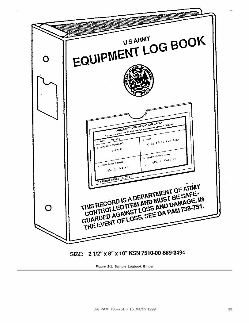
Figure 2-1. Sample Logbook Binder
33DA PAM 738–751 • 15 March 1999

Figure 2-2A. Sample of an Equipment Log Assembly (DA Form 2408) (Illustration #1, Front)
34 DA PAM 738–751 • 15 March 1999

Figure 2-2B. Sample of a Equipment Log Assembly (DA Form 2408) (Illustration #2, Reverse)
35DA PAM 738–751 • 15 March 1999

Figure 2-3. Sample of a completed DA Form 2408–31 (Aircraft Identification Card)
Legend for Figure 2-3:Preparation instructions (by block number and title) forcompleting DA Form 2408–31, Aircraft IdentificationCard
1. MDS. Enter the mission, design, and series for theaircraft or other aviation equipment.
2. AIRCRAFT SERIAL NO. Enter the serial number forthe aircraft (seven numeric digits) or other aviationequipment.
3. UNIT. Enter the name of the unit or organization theaircraft or other aviation equipment is assigned to.
4. CREW CHIEF’S NAME. Enter the rank and name ofthe crew chief or mechanic assigned to the aircraft orother aviation equipment. Leave blank when used tomark the historical binder.
5. SUPERVISOR’S NAME. Enter the rank and name ofthe supervisor (Section Sergeant, Platoon Sergeant, orPlatoon Leader) or person responsible for the aircraft orother aviation equipment. Leave blank when used tomark the historical binder.
36 DA PAM 738–751 • 15 March 1999

Figure 2-4. Sample of a completed DA Form 2408–4–1 (Weapon Record Data)
Legend for Figure 2-4:Preparation instructions (by block number and title) forcompleting a DA Form 2408–4–1, Weapon Record Data
1. END ITEM. Enter "HELICOPTER."
2. SERIAL NUMBER. Enter the aircraft serial number(seven numeric digits).
3. MODEL. Enter the mission, design, series of the air-craft.
4. UNIT. Enter the name of the organization owning theaircraft.
5. WEAPON DATA.
a. DATE FIRED. Enter the date (dd mmm yy) of firing.
Leave blank when making an entry to document mainte-nance actions.
b. CANNON MODEL. Enter the model number of thecannon.
c. SERIAL NO CANNON TUBE. Enter the serial num-ber of the cannon tube.
d. ROUNDS FIRED. Enter the number of rounds firedfor the mission day. Leave blank when making an entryfor replacement or maintenance inspection.
e. CUMULATIVE ROUNDS. Add the rounds fired todayto the previous cumulative rounds. Enter the total cumu-lative rounds fired when the maintenance action is com-pleted.
f. REMARKS. Entries will be made when a component
37DA PAM 738–751 • 15 March 1999

of the weapon is replaced. Other remarks significant tomaintenance, or the operation of the weapon will beentered.
g. NAME OR PID. The person making the entry willenter his or her PID for routine rounds fired, cumulativerounds fired, and any maintenance actions performed.AVIM level armament personnel who complete mainte-nance actions will put their UIC under the PID.
Figure 2-5. Sample of a completed DA Form 2408–4–2 (Weapon Sighting Data OH-58D)
Legend for Figure 2-5:Preparation instructions (by block number and title) forcompletion of a DA Form 2408–4–2, Weapon SightingData (OH-58D)
1. END ITEM: "Helicopter" has been preprinted..
2. SERIAL NUMBER: Enter the serial number (sevennumerical digits) of the end item.
3. MODEL: "OH-58D" has been preprinted.
4. UIC: Enter the unit identification code of the unit oractivity that owns the end item.
5. DATE: Enter the date (dd mmm yy) of the data con-stants reading. Space for five entries (a through e).When components, in block 6, are removed and re-placed enter the date of the new data constants read-ings on the next open line, and line out the previousentry.
6. COMPONENT: Components have been preprinted.
7. DATA CONSTANTS: Enter the data constants infor-mation (black lead pencil), exactly as it appears on eachcomponent data plate. As components are removed andreplaced erase this entry, and enter the data constantsfor the new component.
38 DA PAM 738–751 • 15 March 1999

Note. The use of transparent tape, in block 7, is author-ized. Tape must be of the type you can print on with apencil.
8. MMS COMPONENTS SERIAL NUMBER: Enter theserial number of the Mast Mounted Sight subsystems
components. Space for five entries (a through e). Whencomponents, in block 6, are removed and replaced enterthe new MMS component serial numbers on the nextopen line, and line out the previous entry.
9. SIGNATURE OR PID: The person making the dataconstants entry will enter his or her PID.
Figure 2-6. Sample of a completed DA Form 2408–4–3 (Weapon Sighting Data AH-64A)
Legend for Figure 2-6:Preparation instructions (by block numbers and title) forcompletion of a DA Form 2408–4–3, Weapon SightingData (AH-64A)
Note. The data in blocks 5 through 17 may change. Usepencil for entries so they can be erased and changedwhen components are removed and replaced. The use
of transparent tape is authorized and must be of thetype you can print on with a pencil.
1. END ITEM: "Helicopter" has been preprinted.
2. SERIAL NUMBER: Enter the serial number (sevennumerical digits) of the aircraft.
3. MODEL: "AH-64A" has been preprinted.
39DA PAM 738–751 • 15 March 1999

4. UIC: Enter the unit identification code of the unit oractivity that owns the end item.
5. FCC S/N: Enter the Fire Control Computer serialnumber. If the FCC is removed and replaced, erase theold serial number and enter the new serial number.
6. AIR DATA PROC S/N: Enter the Air Data Processorserial number. If the Air Data Processor is removed andreplaced, erase the old serial number and enter the newserial number.
7. DATE: Enter the date (dd mmm yy) when the AirData Processor thumb wheel setting was entered. If theAir Data Processor is removed and replaced, erase theold date and enter the date the new thumb wheel settingwas entered.
8. THUMBWHEEL SETTING: Enter the assigned thumbwheel setting. If the Air Data Processor is removed andreplaced, erase the old assigned thumb wheel settingand enter the new thumb wheel setting.
9. TADS CORRECTORS-MR.
a. DATE: Enter date (dd mmm yy) when target acquisi-tion designation sight (TADS) Correctors Milliradian(MR) sighting data listed below was entered.
b. LEFT EL=: Enter the Left Elevation (EL) TADS Cor-rector-MR data. LEFT AZ=: Enter the Left Azimuth (AZ)TADS Corrector-MR data.
c. FWD EL=: Enter the Forward (FWD) EL TADS Cor-rector-MR data. FWD AZ=: Enter the FWD AZ TADSCorrector-MR data.
d. RIGHT EL=: Enter the Right EL TADS Corrector-MRdata. RIGHT AZ=: Enter the Right AZ TADS Corrector-MR data.
10. TADS CORRECTORS-MR. Use this block afterEquipment Change Proposal (ECP) 1248 and 1251 areapplied to the aircraft.
a. DATE: Enter date (dd mmm yy) when TADS Correc-tors Milliradian (MR) sighting data listed below wasentered.
b. RATE PITCH=: Enter the Rate Pitch Corrector-MRdata.
c. YAW=: Enter the Yaw Corrector-MR data.
11. BST EGI-MR. Use this block after ECP 1198 isapplied to the aircraft.
a. DATE: Enter date (dd mmm yy) the BST EGI Correc-tors-MR data was entered.
b. AZ=: Enter the Azimuth (AZ) Corrector-MR data.
c. EL=: Enter the Elevation Corrector-MR data.
d. ROLL=: Enter the Roll Corrector-MR data.
12. GUN CORRECTORS-MR.
a. DATE: Enter date (dd mmm yy) when Gun Correc-tors-MR Sighting Data listed below was entered.
b. FWD EL: Enter the FWD EL Gun Correctors-MRdata. AZ: Enter the FWD AZ Gun Correctors-MR data.
c. ROLL LT: Enter the Roll LT Gun Correctors-MR data.RT. Enter the Roll RT Gun Correctors-MR data.
13. PNVS CORRECTORS-MR.
a. Date: Enter date (dd mmm yy) when pilot night visionsensor (PNVS) corrector-MR sighting data was entered.
b. EL=: Enter the EL PNVS Corrector-MR data. AZ=:Enter the AZ PNVS Corrector-MR data.
14. PYLON 1 CORRECTORS-MR.
a. DATE: Enter the date (dd mmm yy) when Pylon 1Correctors-MR sighting data was entered.
b. EL: Enter the EL Pylon 1 Correctors-MR data. AZ:Enter the AZ Pylon 1 Correctors-MR data.
ROLL: Enter the Roll Pylon 1 Correctors-MR data.
15. PYLON 2 CORRECTORS-MR.
a. DATE: Enter the date (dd mmm yy) when Pylon 2Correctors-MR data was entered.
b. EL: Enter the EL Pylon 2 Correctors-MR data. AZ:Enter the AZ Pylon 2 Correctors-MR data.
ROLL: Enter the Roll Pylon 2 Correctors-MR data.
16. PYLON 3 CORRECTORS-MR.
a. DATE: Enter the date (dd mmm yy) when Pylon 3Correctors-MR data was entered.
b. EL: Enter the EL Pylon 3 Correctors-MR data. AZ:Enter the AZ Pylon 3 Correctors-MR data.
ROLL: Enter the Roll Pylon 3 Correctors-MR data.
17. PYLON 4 CORRECTORS-MR.
a. DATE: Enter the date (dd mmm yy) when Pylon 4Correctors-MR data was entered.
b. EL: Enter the EL Pylon 4 Correctors-MR data. AZ:Enter the AZ Pylon 4 Correctors-MR data.
ROLL: Enter the Roll Pylon 4 Correctors-MR data.
40 DA PAM 738–751 • 15 March 1999

Figure 2-7A. Sample of a completed DA Form 2408–12 (Army Aviators Flight Record) (Illustration #1)
Legend for Figure 2-7A:Preparation instructions (by block number and title) forcompleting a DA Form 2408–12, Army Aviator’s FlightRecord (Crew chief/mechanic)
Page of . Enter page number "1" in the first spaceafter the word Page, leave the second space empty, thepilot will fill this in at completion of the mission.
1. DATE. Leave blank, the pilot will enter the date at thebeginning of the first flight of the mission day.
2. SERIAL NUMBER. Enter the aircraft serial number(seven numeric digits).
3. MODEL. Enter the aircraft mission design series.
4. ORGANIZATION. Enter the unit or activity the aircraftis assigned to.
5. STATION. Enter the aircraft’s home station.
6. Blocks a. FLIGHT DATA, b. PERSONNEL DATA,and c. DUTY SYMBOL/FLIGHT SYMBOL/HOURS/SEAT will be filled out by the pilot.
7. SERVICING DATA. At the start of the mission day,the first line will show the grade of fuel and oil, and theresults of the in-tank checks. The crew chief or me-chanic will enter their PID in the "SERVICED BY" blockand enter the location of the aircraft where the inspec-tion was performed in the "LOCATION" block. The per-son servicing the aircraft will enter the following—
FUEL ADDED (GALLONS). The person servicing theaircraft will enter the total quantity of fuel, in gallons,added at one time on the next open line. If fuel wasremoved, place a minus "-" sign in front of the quantityremoved. If no fuel was added or removed, leave blank.
41DA PAM 738–751 • 15 March 1999

Note. The person who serviced the aircraft or super-vised the servicing will make sure the DA Form 2408–12entries match the amount and grade of fuel entries re-corded on the servicing issue slip.
GRADE. Enter the grade of fuel used to service theaircraft.
IN TANKS. Enter the total quantity, in gallons, of fuel inthe tanks after servicing. If the aircraft is not serviced,estimate the amount of fuel aboard the aircraft.
OIL 1. Enter the amount of oil, in quarts, used to servicethe No. 1 engine. If oil was removed place a minus "-"sign in front of the quantity. If none, leave blank.
GRADE. Enter the grade of oil used to service the No. 1engine. If none, leave blank.
OIL 2. Enter the amount of oil, in quarts, used to servicethe No. 2 engine. If oil was removed place a minus "-"sign in front of the quantity. If none, leave blank.
GRADE. Enter the grade of oil used to service the No. 2engine. If none, leave blank.
APU. Enter the amount of oil, in pints, used to servicethe APU. If oil was removed place a minus "-" sign infront of the quantity. If none, leave blank.
GRADE. Enter the grade of oil used to service the APU.If none, leave blank.
OXYGEN. Enter the amount of oxygen, in pounds persquare inch (PSI), used to service the system. If none,leave blank.
Note. Servicing entries are needed when an OxygenSystem is placed aboard the aircraft.
ANTI-ICING. Enter the amount of anti-icing fluid, in gal-lons, used to service the system. If anti-icing fluid wasremoved place a minus "-" sign in front of the quantity. Ifnone, leave blank.
SERVICED BY. Enter the PID of the person doing theservicing, or the person who supervised the servicing onthe same line with the service. If no servicing wasneeded, the person who made the "TOTAL IN-TANKS"check will enter his or her PID in this column.
LOCATION. Enter the location where the aircraft wasserviced. The Federal Aviation Administration (FAA)Identifier in CONUS or the International Civil AviationOrganization (ICAO) Identifier for areas locatedOCONUS may be used. (For example, HOP forCampbell AAF, KY, HLR for Hood AAF, TX, GRK forGray AAF, TX, EDMA for Augsburg Heliport, GE, RKSLfor Seoul AAF Korea.) If an identifier is not assigned,enter the location where the aircraft was serviced. Au-thorized abbreviations are acceptable in this block.
TOTALS. Enter totals of all consumables used for themission day.
Note. Line one of the servicing data is the "TOTAL IN-TANKS" at the start of the mission day, and will not beadded to the totals at the end of the mission day.
Backside DA Form 2408–12 (fig 2–7, illustration no 2)
6. Blocks a. FLIGHT DATA, b. PERSONNEL DATA,and c. DUTY SYMBOL/FLIGHT SYMBOL/HOURS/SEAT will be filled out by the pilot.
8. TOTALS. If more than one DA Form 2408–12 is usedfor the mission day, enter the totals, in block 8, on thelast page. Units using ULLS-A or LAS will enter, when-ever possible, all flight data into the data base at theend of each mission day.
FLIGHT HRS. Enter the total flying hours, in hours andtenths, for the mission day. Reenter total time to the DAForm 2408–13, block 11, CURRENT AIRCRAFTHOURS.
LANDINGS: STD. AUTO. Enter the total number oflandings and touchdown auto rotations made for themission day. Reenter total landings and touchdownautorotations to the DA Form 2408–13, block 11, LAND-INGS.
APU: STARTS. HOURS. Enter the total APU starts andhours, in hours and tenths, for the mission day. Reentertotal APU starts/hours to the DA Form 2408–13, block 7,APU HISTORY STARTS and HOURS TODAY. If theAPU has a start/hour meter use the total starts shownon the start/hour meter at the end of the mission day.Reenter total starts to DA Form 2408–13, block 7, APUHISTORY STARTS TOTAL.
HOUR METER HOURS. If the APU has an hour meter,enter the operating hours on the meter at the end of themission day. Reenter total APU hours to the DA Form2408–13, block 7, APU HISTORY HR METER TOTAL.
STARTS: #1 #2 For multiengine fixed wing aircraft enterthe number of engine starts for the number 1 and num-ber 2 engines. Engine starts while the aircraft is on theground, or in the air will be recorded for each flight,when required by the applicable aircraft maintenancemanual. Reenter the number of engine starts to the DAForm 2408–13, block 9, ENGINE STARTS.
CYCLES. For fixed wing aircraft enter the total numberof times the landing gear was cycled up and down forthe mission day. Reenter total cycles to the DA Form2408–13, block 11, FLIGHT DATA, HSF/CYCLES.
HSF. For the OH-58D helicopter enter the total Hot Sec-tion Factor (HSF) counts for the mission day. Reentertotal HSF counts to the DA Form 2408–13, block 11,FLIGHT DATA, on the Today line in HSF/CYCLES col-umn.
ROUNDS. 7.62: 20MM: 30MM: 40MM: Rocket: TOW:HELLFIRE: . Enter the total number of rounds fired foreach weapon system at the end of the mission day.Reenter the totals to the DA Form 2408–4–1 as re-quired.
Note. For AH-64A Helicopters only, reenter the total
42 DA PAM 738–751 • 15 March 1999

number of 30MM cannon rounds fired today to the DA Form 2408–13, block 8, ROUNDS FIRED AIRFRAMETODAY.
Figure 2-7B. Sample of a completed DA Form 2408–12 (Army Aviators Flight Record) (Illustration #2)
Legend for Figure 2-7B:Preparation instructions (by block number and title) forcompleting DA Form 2408–12, Army Aviators Flight Re-cord (Pilot)
Page of . Enter the total number (black lead pen-cil) of pages of DA Forms 2408–12 used for the currentmission day.
1. DATE. Enter the date (dd mmm yy) at the beginningof the mission day.
Note. 2 through 5. These blocks will, normally, be filledin by the crew chief. Pilot will check the blocks for ac-curacy and completeness. The pilot will complete theseblocks when multiple pages of DA Forms 2408–12 are
needed to complete the mission day. Refer to the crewchief’s 2408–12 instructions.
6.a. FLIGHT DATA. Enter the number of the flight (Forexample, if it is the first flight of the mission day enter a1 here).
Note. The FAA identifier in CONUS or the ICAO identi-fier for areas OCONUS may be used instead of theairfield and place in the FROM and TO blocks.
FROM. Enter the airfield or place that you flew from.The word "LOCAL" may be used in this block for flightswithin the local flying area.
TO. Enter any intermediate stops during the flight (willbe left blank if "LOCAL" was used in the FROM section).
43DA PAM 738–751 • 15 March 1999

TO. Enter the airfield or place you flew to (will be leftblank if "LOCAL" was used in the FROM section).
TIME. FROM. Enter the time (24-hour clock) of take off.
TO. Enter the time (24-hour clock) of intermediate land-ing.
TO. Enter the time (24-hour clock) of landing.
Note. When flying between time zones, the FROM andTO entries will be recorded for the time zone at point oftakeoff.
FLT HRS. Enter the total time, in hours and tenths, forthis flight.
LDG: STD AUTO. Enter the total number of standardlandings, and touchdown auto rotations made duringthis flight. For example, if you landed three times andtwo of the landings were touchdown auto rotations, yourentry would be "1" standard landing and "2" touchdownauto rotations. The number of touchdown auto rotationsmay exceed the number of standard landings.
STARTS #1 #2. For multiengine fixed wing aircraft enterthe number of engine starts for the number 1 engineand number 2 engine. Engine starts while the aircraft ison the ground, or in the air will be recorded for eachflight when required by the aircraft maintenance manual.
MISSION ID. STD. Enter the mission symbol that de-scribes the purpose of the flight per AR 95–1. (MissionSymbols can be found on the DA Form 2408 in front ofthe logbook.) For flight simulators, leave blank or asprescribed by the Commander of the Synthetic FlightTraining System (SFTS) facility.
CONFIG. Leave blank.
LOADS: INTERNAL, EXTERNAL, PASSENGERS.When carrying internal cargo type loads, enter the totalnumber of pounds of the internal load; when carryingexternal loads, enter the total number of pounds of theexternal load; when carrying passengers, enter numberof passengers aboard aircraft during flight. Leave blankwhen there are no passengers, or internal or externalcargo loaded on the aircraft.
CYC. For fixed wing aircraft enter the total number oftimes the landing gear was cycled up and down for thisflight.
HSF. For OH-58D helicopters enter Hot Section Factorcounts displayed on the engine monitor page displayedon the multifunction display (MFD).
ROUNDS. 7.62 20MM 30MM 40MM ROCKET TOWHELLFIRE. Enter the number rounds fired from eachweapon system for this flight. When a block is not pres-ent for the type of weapon installed on the aircraft, lineout the title on an unused block, and enter the weapontype and number of round fired. If none, or it does notapply leave blank.
STATUS. 7.62 20MM 30MM 40MM ROCKET TOWHELLFIRE. Leave these blocks blank.
HIT CHECK NO. 1 ENGINE. Record the HIT check
deviation from the established baseline for No. 1 Engine(first flight of the mission day). If it does not apply, leaveblank.
HIT CHECK NO. 2 ENGINE. Record the HIT checkdeviation from the established baseline for No. 2 Engine(first flight of the mission day). If it does not apply, leaveblank.
APU. STARTS. HOURS. Enter the number of starts forthe APU, if required by the TM-23 and/or TB1–1500–341–01. For APUs without an hour meter, enterthe time the APU was operated, in hours and tenths, ifrequired by the TM-23 and/or TB 1–1500–341–01. IfAPU starts are shown on the Start/Hour Meter, read themeter after the last flight of the mission day and enterthe number of starts shown on the meter in block 8,TOTALS, APU STARTS portion. If it does not apply,leave blank.
HOUR METER HRS. Leave blank.
6b. PERSONNEL DATA. If your mission day has flightsthat overlap into the next calendar day, and you need toknow the actual date of takeoff, for each flight, you canenter the date (dd mmm yy) of takeoff in the title bar ofblock 6b, PERSONNEL DATA, preceding the word"PERSONNEL."
NAME. Enter last name and first name initial of eachcrewmember of each flight.
RANK. Enter rank of each crewmember for each flight.For example, CPT., MAJ., LTC., WO1, CW2, SPC,SGT., SSG., SFC., MSG., and so on.
PID/SSAN. Enter the PID for each crewmember.
6c. DUTY SYMBOL/FLIGHT SYMBOL/HOURS/SEAT.
Note. Symbols can be found on the DA Form 2408 infront of the logbook.
DS. Enter the flying duty symbol, per AR 95–1, thatshows the type of duty completed by each crewmemberlisted. If any crewmember changes their duty status,during the flight, enter the new symbol in the next open"DS" column to the right.
FS. Enter the flight condition symbol, per AR 95–1.
HR. Enter the flying time, in hours and tenths, flown foreach duty and flight symbol. The sum of these timesmust equal the total time in block 6a, FLT HRS.
S. Enter the seat each crewmember sat in for the flight,"F" for Front, "B" for Back. This applies to tandem seataircraft only (AH-1, AH-64).
Note. After all crewmembers for the mission have beenlisted in block 6b, PERSONNEL DATA, enter "LASTENTRY" on the next open line. If the number of crew-members exceeds the space available for the flight, con-tinue recording the names in the next open block 6b,PERSONNEL DATA. List only the persons on flying sta-tus. Any changes made in the PERSONNEL DATA,DUTY SYMBOL, FLIGHT SYMBOL, and HOURS blocks
44 DA PAM 738–751 • 15 March 1999

must be initialed by the pilot in command. Enter anyother information needed locally.
7. SERVICING DATA. Entries normally will be made bythe crew chief according to figure 2–7, and the entrieswill be checked by the pilot in command.
BACK SIDE OF DA FORM 2408–12 (fig 2–7, illustration2)
6. FLIGHT DATA. Pilots’ entries are the same as on thefront side, except there is no requirement for a HITcheck.
8. TOTALS. The person closing out the form, normallythe crew chief or assigned mechanic will fill in the Totalsin each block that applies per previous instructions.
Figure 2-8A. Sample of a completed DA Form 2408–13 (Aircraft Status Information Record) (Illustration #1)
45DA PAM 738–751 • 15 March 1999

Figure 2-8B. Sample of a completed DA Form 2408–13 (Aircraft Status Information Record) (Illustration #2)
Legend for Figure 2-8B:Preparation instructions (by block title) for completing aDA Form 2408–13, Aircraft Status Information Record
DATE. The pilot will enter the date (dd mmm yy) for thefirst flight of the mission day.
NUMBER OF PAGES IN FLIGHT PACK. Enter the totalnumber of pages (black lead pencil) in the Flight Pack(DA Forms 2408–13–1, 2408–13–2, and 2408–13–3.)This entry will change when a DA Form 2408–13–1,2408–13–2 or 2408–13–3 is added to the Flight Pack.
1. AIRCRAFT SERIAL NUMBER. Enter the aircraft se-rial number (seven numerics, no dashes). Computergenerated for ULLS-A/LAS users.
2. MODEL. Enter the aircraft Mission Design Series.Computer generated for ULLS-A/LAS users.
3. UIC. Enter the unit identification code of the unit oractivity owning the aircraft. Computer generated forULLS-A/LAS users.
4. STATION. Enter the aircraft’s home station. Com-puter generated for ULLS-A/LAS users.
5. NAME OF CE/MECH. Enter the name of the as-signed crew chief or mechanic.
6. ENGINE HIT READINGS.
Note. Leave these blocks blank when using the manualmethod of recordkeeping. Computer generated whenusing ULLS-A/LAS.
DATE. Dates of the last five HIT readings.
46 DA PAM 738–751 • 15 March 1999

NO 1. Last five HIT readings for NO 1 engine.
NO 2. Last five HIT readings for NO 2 engine.
7. APU HISTORY.
HOURS, CURRENT. Applies to aircraft without an hourmeter installed. Enter the total APU operating hours, inhours and tenths, from the last mission day DA Form2408–13. Computer generated for users of ULLS-A/LAS.
HOURS, TODAY. Enter the APU operating hours, inhours and tenths, for the current mission day. Get thisinformation from the backside of the current DA Form2408–12, block 8, TOTALS, APU: HOURS.
HOURS, TOTAL. Add the CURRENT and TODAY oper-ating hours for the total operating hours.
STARTS, CURRENT. Enter the total APU Starts fromthe last mission day DA Form 2408–13. Computer gen-erated for users of ULLS-A/LAS.
STARTS, TODAY. Enter the number of APU starts forthe current mission day. Get this information from thebackside of the current DA Form 2408–12, block 8, TO-TALS, APU: STARTS. If APU starts are shown on aStart/Hour Meter, leave this block blank.
STARTS, TOTAL. Add the CURRENT and TODAYSTARTS for the total starts. If starts are shown on aStart/Hour Meter enter the number of starts on the me-ter, or from the backside of current DA Form 2408–12,block 8, TOTALS, APU: STARTS.
HR METER, CURRENT. Applies to aircraft with an hourmeter installed. Enter the total APU hour meter reading.Get the information from the last mission day DA Form2408–13. Computer generated for users of ULLS-A/LAS.
HR METER, TOTAL. Enter the APU hour meter read-ing. Get this information from the backside of the currentDA Form 2408–12, block 8. TOTALS, HOUR METERHOURS.
8. ROUNDS FIRED AIRFRAME. For AH-64A helicop-ters, all others leave blank.
CURRENT. Enter the total rounds fired from the 30MMcannon(s) presently and previously installed in the air-craft. Get this information from the last mission day DAForm 2408–13. Computer generated for users of ULLS-A/LAS.
TODAY. Enter the number of rounds fired from the30MM cannon installed. Get this information from thebackside of the current DA Form 2408–12, block 8. TO-TALS, ROUNDS, 30MM.
TOTAL. Add the CURRENT and TODAY rounds firedfor the total rounds fired.
9. ENGINE STARTS
Note. For multiengine fixed wing aircraft.
NO 1, CURRENT. Enter the total number 1 enginestarts from the last mission day DA Form 2408–13.Computer generated for users of ULLS-A/LAS.
NO 1, TODAY. Enter the total number 1 engine startsfor the current mission day. Get this information from thebackside of the current DA Form 2408–12, block 8, TO-TALS, STARTS #1.
NO 1, TOTAL. Add the CURRENT and TODAY enginestarts for the total number 1 engine starts.
NO 2, CURRENT. Enter the total number 2 enginestarts from the last mission day DA Form 2408–13.Computer generated for users of ULLS-A/LAS.
NO 2, TODAY. Enter the total number 2 engine startsfor the current mission day. Get this information from thebackside of the current DA Form 2408–12, block 8, TO-TALS, STARTS #2.
NO 2, TOTAL. Add the CURRENT and TODAY enginestarts for the total number 2 engine starts.
10. SYSTEM STATUS. In these boxes enter the statussymbols, for the most serious uncorrected faults for air-craft, and mission related systems listed in the FaultInformation block on the DA Form 2408–13–1, DA Form2408–13–2, DA Form 2408–13–3, and the DA Form2408–14–1 starting in the top left box. When there areno faults on the aircraft or mission related systems, themechanic or crew chief will enter their last name initial. Ifa fault is corrected, or a new fault is added, and thestatus changes, enter the new status symbol in the nextopen box to the right (for aircraft, there are 14 boxesthat can be used). When all boxes are used, make outanother DA Form 2408–13 and enter the status symbolin the top left box. Once you have entered a statussymbol in any column in the SYSTEM STATUS block,you cannot erase, initial over, or change it. Record anystatus changes during the mission day in the next openbox to the right. Clear any incorrect entries as shown inparagraph 1–8.
ACFT. Enter the current condition status symbol for theaircraft starting in the top left box. Computer generatedfor users of ULLS-A/LAS.
ARM. Enter the current status symbol for mission re-lated armament systems starting in the left box. Com-puter generated for users of ULLS-A/LAS.
ELECT. Enter the current status symbol for missionrelated electronic equipment, such as, radar, camera,infrared, and so on, starting in the left box. Computergenerated for users of ULLS-A/LAS.
OTHER. Enter the current status symbol for any othermission related aviation associated equipment, such as,rescue hoist starting in the left box. Computer generatedfor users of ULLS-A/LAS.
11. FLIGHT DATA.
AIRCRAFT HOURS
CURRENT. Enter the current total aircraft operating
47DA PAM 738–751 • 15 March 1999

time, in hours and tenths. This time can be found on theprevious mission day DA Form 2408–13. Computer gen-erated for users of ULLS-A/LAS.
TODAY. Enter the aircraft flying time, in hours andtenths, for Today’s mission. Get this time from the back-side of the DA Form 2408–12, block 8, TOTALS,FLIGHT HRS.
TOTAL. Add the CURRENT and TODAY time for thetotal time, in hours and tenths.
LANDINGS, STD AUTO.
CURRENT. Enter the total standard landings and touch-down autorotations since the first day of the reportingperiod. Landings and autorotations can be found on theprevious mission day DA Form 2408–13. Computer gen-erated for users of the ULLS-A/LAS.
TODAY. Enter the standard landings and touchdownautorotations accomplished today. Get this informationfrom the backside of the DA Form 2408–12, block 8,TOTALS, LANDINGS: STD, AUTO.
TOTAL. Add the CURRENT to the TODAY for the totallandings andautorotations. If this form is for the last dayof the report period, do not reenter the total landingsand touchdown auto rotations to a new DA Form2408–13.
Note. Before the first flight of a new 1352 ReportingPeriod, line out the CURRENT Landings and enter "0."DO NOT zero the landings if the aircraft TM-23 requirescomponent replacement or inspections based on totalcumulative landings.
HSF/CYCLES.
CURRENT. For fixed wing aircraft with retractable land-ing gear, enter the total cycles for the landing gear. ForOH-58 aircraft enter the total HSF counts. Cycles orHSF counts can be found on the previous mission dayDA Form 2408–13. Computer generated for users ofULLS-A/LAS.
TODAY. For fixed wing aircraft with retractable landinggear enter the total number of times the landing gearwas cycled today. Get this information from the backsideof the DA Form 2408–12, block 8, TOTALS, CYCLES.Do not enter any HSF counts on this line.
TOTAL. For fixed wing aircraft with retractable landinggear add the CURRENT to the TODAY for total cycles.For the OH-58D helicopter enter the mission day’s HSFcounts on this line. Get this count from the backside ofthe DA Form 2408–12, block 8, TOTALS, HSF.
Note. Compare the HSF counts in this block to the read-ings in the CURRENT Block to ensure proper operationof the multifunction display. When an engine is replaced,enter the total HSF counts on the DA Form 2408–16,block 7, SIGNIFICANT HISTORICAL DATA and on DAForm 2410, block 13a, LCF 1. Line out the CURRENTHSF counts on the DA Form 2408–13 when the replace-ment engine is installed and enter the new HSF countsfor the replacement engine. Update the multifunctiondisplay with the correct HSF counts for the replacementengine.
12. SCHEDULED INSPECTION INFORMATION.
a. HOURS OF OPERATION SINCE LAST GENERA-TION. Leave blank when using the manual method ofrecordkeeping. Computer generated for ULLS-A/LASusers.
b. NEXT PHASE/SCHEDULED INSP (NO). Enter thenumber of the next phase or scheduled inspection.Computer generated by ULLS-A.
c. NEXT PHASE/SCHEDULED INSP DUE AT. Enterthe aircraft hours the next phase or scheduled inspec-tion is due. Computer generated by ULLS-A.
d. HOURS OF OPERATION TO NEXT PHASE/SCHEDULED INSPECTION. Leave blank when usingthe manual method of recordkeeping. Computer gener-ated by ULLS-A.
e. PMD DUE. This block is left blank for Non-PMD air-craft.
DATE COMPLETED. Enter the date (dd mmm yy) thepreventive maintenance daily inspection was completed.DO NOT erase. For aircraft under PMS maintenanceleave blank.
PID. Enter the PID of the individual who completed thedaily inspection.
Note. If any faults are found during the PMD they will beentered on the DA Form 2408–13–1 in the first openFault Information block.
13. LOCAL USE: Enter the ground run time and startsfor APU’s without hour meters that require operatinghour and start data per the TM 23 and TB1–1500–341–01 (For example, 10 JAN 95, 1 start, .5hrs.) This data will be combined with the hours and startdata for the first flight of the next mission day andentered on DA Form 2408–12, block 6.a., APU:STARTS HOURS for that flight. Other data may beentered in this block as directed by unit commander.
48 DA PAM 738–751 • 15 March 1999

Figure 2-9A. Sample of a completed DA Form 2408–13–1 (Aircraft Inspection and Maintenance Record) (Illustration #1)
49DA PAM 738–751 • 15 March 1999

Figure 2-9B. Sample of a Completed DA Form 2408–13–1 (Aircraft Inspection and Maintenance Record) (Illustration #2)
50 DA PAM 738–751 • 15 March 1999

Figure 2-9C. Sample of a completed DA Form 2408–13–1 (Aircraft Inspection and Maintenance Record) (Illustration #3)
Legend for Figure 2-9C:Preparation instructions (by block number and title) forcompletion of a DA Form 2408–13–1, Aircraft Inspectionand Maintenance Record
1. AIRCRAFT SERIAL NUMBER. Enter the completeaircraft serial number (seven numerical digits).
2. MODEL. Enter the aircraft mission, design, and se-ries.
3. DATE. The pilot will enter the date (dd mmm yy) ofthe first takeoff of the mission day.
4. PAGE. Pages are to be numbered by the mechanic,crew chief or pilot at the beginning of each mission day.Enter the page number (black lead pencil) beginningwith "1." As additional DA Form 2408–13–1 are added,enter the next page number.
PART I—FAULT INFORMATION. Any person who dis-covers a fault or condition affecting the operation/flightof the aircraft, training device/simulator, or mission re-lated equipment aboard the aircraft will record it in aFAULT INFORMATION block.
STATUS. Enter the proper status symbol in this block.Once a status symbol is entered in the STATUS Block,it will not be erased or changed even if entered in error(para 1–8). The person who corrects a red "dash" or reddiagonal "/" fault will enter their last name initial over thestatus symbol. A red "X" or circled red "X" status symbolwill be initialed over by a qualified designated represent-ative appointed by the unit or activity commander. Whenclearing a red "X" or circled red "X" a ballpoint pen withblue or black ink, or technical inspector’s stamp may beused. The maintenance test pilot will initial the symbolafter they complete the test flight and the aircraft iscleared for flight. When more than one person com-pletes the corrective action for a fault, other than aphase, periodic, or progressive phase maintenance, the
51DA PAM 738–751 • 15 March 1999

senior mechanic, who performed part of the correctiveaction will initial the status symbol for entries with a reddiagonal "/" or red dash "-" status. Initials placed in thisblock will not be erased.
Note. Changing the status symbol, for armament, elec-tronic, and other mission-related equipment, to a lessserious status symbol is not needed for a one timeevacuation mission per paragraph 1–10.
SYS. ULLS-A users only. Enter the system code thatshows which system the fault is related to. SystemCodes can be found on the DA Form 2408 in front of thelogbook. Code "A" will be used for all aircraft faults.Electronic faults that do not affect aircraft readiness andare not reportable under AMSS will also use code "A."Electronic equipment faults that affect readiness and arereportable under AMSS will use code "E." All armamentfaults will use code "W."
DATE. Enter the date (dd mmm yy) a fault is discov-ered, or a remark is made. When the fault is reenteredfrom the DA Form 2408–14–1 the original date of thefault will be entered.
NO. Leave blank for units using the manual recordkeep-ing system. Computer generated by ULLS-A.
TIME. Enter the time (24-hour clock) the fault was dis-covered or an inspection/service was entered. When afault is reentered from the DA Form 2408–14–1 leavethis block blank.
PID. The person making the entry will enter his or herpersonnel identifier.
FAULT/REMARKS
(a) The person who finds a fault or removes a compo-nent/module or part will immediately make an entry onthe first open line in the FAULT/REMARKS section.Enter the proper status symbol in the STATUS block,and update the status symbol on the DA Form 2408–13,SYSTEM STATUS block, when it applies.
(b) For ULLS-A/LAS users, when related maintenanceactions are needed to correct a fault, enter the primaryfault in the first open FAULT INFORMATION block onthe DA Form 2408–13–1. The related maintenance ac-tions will be entered on a DA Form 2408–13–2 (RelatedMaintenance Actions Record). For users under the man-ual recordkeeping system, if only one related mainte-nance action is needed to correct a fault, it may beentered on the DA Form 2408–13–1. If more than onerelated maintenance action is required, the related main-tenance actions will be entered on a DA Form2408–13–2.
(c) After a flight, if no faults are noted, the pilot will entera remark such as "Flt 1 OK," then enter his or her PID,the date, time, and aircraft hours in the correspondingblocks. If the pilot has a remark to make regarding theaircraft or installed mission-related equipment, he or shewill enter the remark in the FAULT/REMARKS section,PID in the PID block, and the date in the DATE block. Iffaults or deficiencies are noted during the flight, the pilotwill precede the fault or deficiency entry with "FLT (cor-responding flight number for the mission day)," or "Test
Flight" if the fault or deficiency is discovered during atest flight, along with his or her PID in the PID block,and all applicable portions of the FAULT INFORMA-TION block. Use as many Fault Information blocks asnecessary to enter faults, deficiencies, and remarks;with only one fault/remark per FAULT INFORMATIONblock. If more space is needed, to enter a fault/remark,than is provided in a FAULT INFORMATION block thenenter "Continued" on the last line of the FAULT/REMARKS section, and continue the fault/remark in thenext open FAULT INFORMATION block. If the fault/remark will not fit the space provided in the last FAULTINFORMATION block on the backside of the form, thenenter "Continued," at the end of the last line of theFAULT/REMARKS section, and continue the fault/remark on the next page.
(d) When a test flight or MOC is needed after mainte-nance, enter a red dash in the STATUS block, andwhen it applies update the DA Form 2408–13, SYSTEMSTATUS block. In the FAULT/REMARKS section enter"Test Flight Required," "Test flight due," "MTF required,""MTF due," or "MOC Required" and give the reason(s)why.
(e) Entries are also needed for aircraft accidents, forcedor precautionary landings, airspeed limitations, or enginetorque exceeded. Include the cause and damage, if any.
(f) If an aircraft becomes contaminated, refer to para-graph 1–8 and appendix B.
AC HRS. Enter the actual aircraft hours at the time theinspection or service was entered, or when the fault wasdiscovered. Leave blank, when a fault is reentered fromthe DA Form 2408–14–1.
WHEN DISC. ULLS-A/LAS users. Enter the appropri-ate When Discovered Code, for faults and discrepan-cies, from DA Form 2408 or table 1–4. Leave blankwhen a remark is in the FAULT/REMARKS section.
HOW REC. ULLS-A/LAS users. Enter the appropriateHow Recognized Code, for faults and discrepancies,from DA Form 2408 or table 1–5. Leave blank when aremark is in the FAULT/REMARKS section.
MAL EFF. ULLS-A/LAS users. Enter the appropriateMalfunction Effect code, for faults and discrepancies,from DA Form 2408 or table 1–6. Leave blank when aremark is in the FAULT/REMARKS section.
DELAY Enter the reason for the delay. For example,enter the work order number of the work request to fixthe fault or condition, or enter the supply requisitionnumber for a repair part that is required to repair thefault, or enter "2408–13–2" when a DA Form 2408–13–2is needed to list related maintenance actions for clearingthe fault or deficiencies. When a fault is reentered fromthe DA Form 2408–14–1 leave blank.
WUC. ULLS-A/LAS users. Enter the work unit code(WUC) that best describes which component or modulethe fault or inspection entry pertains to. If a WUC, thatapplies to the component, module, or area, has notbeen established enter the functional group code, fromDA Form 2408 or table 1–10, which best fits the fault orinspection. Leave blank when a remark is in the FAULT/REMARKS section.
52 DA PAM 738–751 • 15 March 1999

PART II—CORRECTING INFORMATION.
(a) When a fault, deficiency, condition, or incorrect entryis corrected; directives (such as, SOF messages,ASAMs, TBs, or MWO’s) are applied; and components/modules or other repair parts are removed and reinstal-led, or replaced the person making the corrective actionwill enter the action taken in the CORRECTING INFOR-MATION block, which is to the right of the FAULT IN-FORMATION Block. Using words or phrases, such as"applied," "tested," "installed," "serviced," "replaced,""repaired," "adjusted," or "erroneous entry," with otherbrief information about the action, will be enough to de-scribe the corrective action. It will not be considered inerror if you use one or more words to describe actiontaken. DO NOT use the word "corrected."
Note. A few examples of what can be entered in theFAULT/REMARKS, and CORRECTING INFORMATIONsections are:
(1) "PMD due," "PMS due," "Phase Insp Due," "#2Phase Insp due" —"completed," "PMD completed,""PMS completed," "Inspection completed," "#2 PhaseInsp completed," and so on.
(2) "Test flight due," "Test flight required," "MOC re-quired" —"completed," "Test flight completed," "Mainte-nance test flight completed," "MTF completed," "MOCcompleted," "Maintenance operational check OK," andso on.
(3) "Mag compass calibration due" — "completed," "Magcompass Cal. completed."
(4) "Copilot’s door window crazed" — "Replaced,""Changed," "Window replaced," "Replaced window assy," "Replaced copilot’s door window," "Changed window."
(5) "Oxygen System low" — "Serviced," "Oxy. Sys Serv-iced," "system serviced."
(6) "Engine deck torn" — "Replaced," "Eng. deck repl.,""Deck replaced."
(b) Upon completion of the corrective action, the personmaking the corrective action will place his or her PID inthe PID block, and last name initial over the status sym-bol in the FAULT INFORMATION block. To clear a red"X" or circled red "X" symbol, the completed action mustbe inspected by the commander or designated repre-sentative per paragraph 1–9. If the action is found to besatisfactory, the statement "Insp OK," and the inspec-tor’s signature will be entered on the line following theaction taken. If there is no space, the signature may beplaced above the corrective action taken. The inspectorwill then enter his or her PID in the TIPID Block, placelast name initial over the status symbol in the FAULTINFORMATION block, and change the status symbol inthe SYSTEM STATUS Block on the DA Form 2408–13if it applies.
Note. A technical inspector’s stamp may be used in-stead of the statement and signature. If more than onetechnical inspector performed the technical inspectionsto complete the fault correction, the senior technical in-spector performing the inspection will enter his or her
PID in the TIPID Block, enter "Insp OK," and signaturein Action section.
(c) When corrective action is taken by other than theparent unit or designated support activities, the persontaking the action will enter his or her unit or activitydesignation in this block. The unit delegation orders areofficial, and allow the delegated persons to sign off red"X" or circled red "X" entries on aircraft belonging toother units or activities. Qualified designated representa-tives may also certify work performed, or do one timeinspections on aircraft belonging to other units or activi-ties. They will enter the unit or activity in this block, andplace his or her last name initial over the status symbolin the FAULT INFORMATION block.
(d) Entries on the DA Form 2408–13–1 that call forentries on historical forms, and records (such as, re-placement of reportable items, ASAMs, SOF messages,TBs, MWO applications, special inspections/services/re-placements performed, and so forth) is the responsibilityof the technical inspector that inspected the correctiveaction.
Note. A checklist (table 3–9) is provided to help ensurethat entries are made on all forms and records thatapply, before releasing aircraft from maintenance. Thechecklist is also provided to verify that a quality inspec-tion of forms, records, and files has been done. The useof the checklist is not mandatory; however, it is recom-mended for newly assigned maintenance and qualitycontrol personnel.
DATE. Enter date (dd mmm yy) of the corrective action.
TIME. Enter the time of day (24 hour clock) the correc-tive action was completed.
ACFT HRS. Enter the actual aircraft hours when thecorrective action, on a fault, condition, inspection, serv-ice, MOC, or test flight, was completed.
ROUNDS. Enter the cumulative rounds fired from DAForm 2408–4–1, block 5e for armament system faults,discrepancies and inspections.
ACTION CODE. ULLS-A/LAS users. Enter the ActionCode from DA Form 2408 or table 1–9 that best de-scribes the action taken.
WUC. ULLS-A/LAS users. Enter the Work Unit Codethat best describes which component/module or part thecorrective action pertains to. If a WUC has not beenestablished, that applies to the component/module, partor area, enter the functional group code from DA Form2408 or table 1–10 that best fits the corrective action.The corrective action WUC may be different from thewhen discovered WUC.
ACTION. Enter an abbreviated explanation of the actiontaken.
PID. Enter the personnel identifier of the person(s) ac-complishing all or part of the corrective action. If a DAForm 2408–13–2 was used, all personnel completingactions on that form will enter their PID on this form.When a scheduled inspection (such as, phase, periodic,or progressive phase maintenance) is completed, DONOT reenter the PIDs from the maintenance checklist.
53DA PAM 738–751 • 15 March 1999

The maintenance supervisor will enter his or her PIDcertifying completion of the inspection.
CAT. ULLS-A/LAS users. Enter the level of mainte-nance for the action taken ("C" for crew level, "O" forAVUM level, "F" for AVIM level, or "D" for depot level). Ifan individual performs both crew level and AVUM levelwork to perform the corrective action, they will entertheir PID twice, once for crew level maintenance hoursand once for AVUM level maintenance hours.
Note. When DA Form 2408–13–1, Oct 91, or DA Form2408–13–3, Nov 91, is used the category will be enteredin the HOURS Block preceding the manhours expendedby each individual who corrected the fault.
HRS. ULLS-A/LAS users only. Enter the direct "handson" manhours, in hours and tenths, expended during thecorrective action. This time does not include the timeexpended chasing parts or tools, but does include timeexpended filling out forms and records. All personnelcompleting related maintenance actions on a DA Form2408–13–2 will enter manhours expended in this block.At the completion of a scheduled inspection (such as,phase, periodic or progressive phase maintenance) thesupervisor will enter the total number of manhours ex-pended to complete the visual inspection including anyrequired disassembly. The supervisor will separate themanhours by category of maintenance. When extensive
maintenance is performed, such as an engine replace-ment, and there are not enough HRS blocks availablefor all the mechanics performing maintenance to entertheir manhours, the maintenance supervisor may con-solidate the manhours by category and use his or herPID to enter the manhours.
Note. When DA Form 2408–13–1, Oct 91, or DA Form2408–13–3, Nov 91, is used the CMH, OMH, FMH, andDMH blocks will be left blank.
TIPID. Enter the personnel identifier of the technical in-spector who inspected the maintenance action. If morethan one technical inspector performed the technical in-spections of the maintenance action or related mainte-nance actions, the senior technical inspector, performingthe inspection, will enter his or her PID in this block.
TI MANHOURS. ULLS-A/LAS users only. This spaceis provided for the Technical Inspector(s) to enter themanhours, in hours and tenths, it took to inspect thecorrective action. This will include the time used for theinspection, and to complete forms and records. If morethan one technical inspector performed the technical in-spections on the maintenance action or related mainte-nance actions, the senior technical inspector, performingthe inspection will enter the total manhours used tocomplete the inspection.
54 DA PAM 738–751 • 15 March 1999

Figure 2-10A. Sample of a completed DA Form 2408–13–2 (Related Maintenance Actions Record) (Illustration #1, Front)
55DA PAM 738–751 • 15 March 1999

Figure 2-10B. Sample of a completed DA Form 2408–13–2 (Related Maintenance Actions Record) (Illustration #2, Reverse)
56 DA PAM 738–751 • 15 March 1999

Figure 2-11. Sample of a completed DA Form 2408–13–2 (Related Maintenance Action Record) (Component Repair)
Legend for Figure 2-11:Preparation instructions (by block number and title) forcompletion of a DA Form 2408–13–2, Related Mainte-nance Actions Record
This form will be used as a supplemental sheet for theDA Forms 2408–13–1 and 2408–13–3.
DATE. Enter the date (dd mmm yy) the DA Form2408–13–2 was started.
Page. Each form in the Flight Pack will be assigned apage number starting with page 1 for the first DA Form2408–13–1 in the logbook. When a new DA Form2408–13–2 is added to the logbook it will be assigned apage number. If there are three DA Forms 2408–13–1 inthe logbook, when the 2408–13–2 is added, the pagenumber of the DA Form 2408–13–2 will be 4. When thisform is used to document related maintenance actionsfor AVIM or Depot component repair, the DA Form
2408–13–3 used to document initial inspection of thecomponent will be page 1. The first DA Form2408–13–2 will be page 2, the second page will be 3,and so on.
1. STATUS. Enter the status symbol assigned to thefault or deficiency listed on the DA Form 2408–13–1 or2408–13–3. DO NOT initial over the status symbol inthis block. When the fault, in block 7, is corrected, clearthe status for the fault on the DA Form 2408–13–1 or2408–13–3.
2. SERIAL NUMBER. Enter the serial number (sevennumeric characters) of the aircraft. When this form isused to document AVIM or Depot level componentrepair, enter the component serial number.
3. SYSTEM CODE. Enter the system code of the faultfrom the DA Form 2408–13–1 or 2408–13–3, FAULTINFORMATION block.
57DA PAM 738–751 • 15 March 1999
4. TIME. Leave blank.
5. FAULT DATE. Enter the date (dd mmm yy) of thefault from the DA Form 2408–13–1 or 2408–13–3,FAULT INFORMATION block.
6. FAULT NUMBER. ULLS-A/LAS user. If a fault num-ber has been assigned by the computer, enter the faultnumber. Leave blank if no fault number has been as-signed.
7. FAULT. Enter the fault exactly as it is written on theDA Form 2408–13–1 or 2408–13–3. Only one fault willbe written in this block.
Note. When using DA Form 2408–13–2, NOV 91, do notenter a fault in block 7 on the reverse side of the form.Only one fault will be entered on each form.
8. STA. The person entering related maintenance ac-tions on this form will enter the proper condition statussymbol according to the seriousness of each relatedmaintenance action (see para 1–8).
9. RELATED MAINTENANCE ACTIONS. Enter a shortdescription of the related maintenance action to be doneto clear the fault listed in block 7. For example, thestatus symbol on the DA Form 2408–13–1 is a Red "X"for foreign object damage (FOD) to engine, you wouldenter "Engine inlet cowling removed," "Main drive shaftremoved," and so forth. Enter only one related mainte-nance action at a time in the space provided. Use asmany lines and forms, as needed, to enter related main-tenance actions called for to clear the fault listed on theDA Form 2408–13–1 or 2408–13–3. The signature fol-lowing the maintenance related action is not needed inthis block. If the unit or activity commander requires asignature following the maintenance related action, thismust be covered in the unit or activity Standard Operat-ing Procedures (SOP).
Note. If both sides of the form are filled and more roomis needed, enter "Continued," or "Cont" at the end onthe last line, and start a new DA Form 2408–13–2. Onthe new form enter the fault in Block 7 as it was origi-nally entered and enter the word "continued" or "cont"
following the fault. Blocks 1 through 6 do not have to becompleted.
10. ACTION. Enter the corrective maintenance actiontaken. DO NOT use the word "corrected." A few exam-ples of what can be entered are:
a. "Copilot’s door removed"—"Reinstalled door," "Re-placed door," "Reinstalled copilot’s door," "Doorreinstalled," "Copilot’s door replaced."
b. "Copilot’s door window removed"—"Reinstalled,""Window replaced," "Copilot’s door window reinstalled,""Reinstalled window," "Installed window."
c. "White main rotor PC link removed"—"reinstalled,""Reinstalled MR PC link," "Reinstalled white MR PCLink."
d. "Engine inlet cowling removed"—"Replaced,""Reinstalled," "Replaced cowling," "Engine inlet cowlreinstalled."
11. PID. The person completing the related mainte-nance action will place his or her PID in this block.
12. CAT. ULLS-A/LAS users. Enter the level of mainte-nance for the action taken ("C" for crew level, "O" forAVUM, "F" for AVIM, and "D" for depot).
Note. When using the DA Form 2408–13–2, Nov 91,enter the category of maintenance in the MMH Blockpreceding the manhours.
13. MMH. ULLS-A/LAS users. Enter the direct "handson" manhours, in hours and tenths, to complete theaction taken. Total each level of maintenance by PIDand enter the total on the DA Form 2408–13–1 or2408–13–3, HRS block.
Note. If the action taken to clear a related maintenanceaction entered on the DA Form 2408–13–2 is foundunsatisfactory the status symbol in block 8, no matterhow serious will not be initialed over.
58 DA PAM 738–751 • 15 March 1999
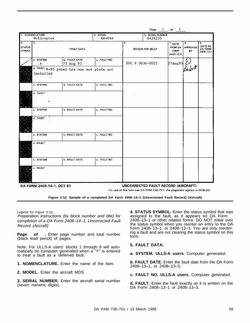
Figure 2-12. Sample of a completed DA Form 2408–14–1 (Uncorrected Fault Record) (Aircraft)
Legend for Figure 2-12:Preparation instructions (by block number and title) forcompletion of a DA Form 2408–14–1, Uncorrected FaultRecord (Aircraft)
Page of . Enter page number and total number(black lead pencil) of pages.
Note. For ULLS-A users’ blocks 1 through 8 will auto-matically be computer generated when a "Y" is enteredto treat a fault as a ’deferred fault.’
1. NOMENCLATURE. Enter the name of the item.
2. MODEL. Enter the aircraft MDS.
3. SERIAL NUMBER. Enter the aircraft serial number(seven numeric digits).
4. STATUS SYMBOL. Enter the status symbol that wasassigned to the fault, as it appears on DA Form2408–13–1 or other related forms. DO NOT initial overthe status symbol when you reenter an entry to the DAForm 2408–13–1, or 2408–13–3. You are only reenter-ing a fault and are not clearing the status symbol on thisform.
5. FAULT DATA:
a. SYSTEM. ULLS-A users. Computer generated.
b. FAULT DATE. Enter the fault date from the DA Form2408–13–1, or 2408–13–3.
c. FAULT NO. ULLS-A users. Computer generated.
d. FAULT. Enter the fault exactly as it is written on theDA Form 2408–13–1 or 2408–13–3.
59DA PAM 738–751 • 15 March 1999

6. REASON FOR DELAY. Enter the reason for delay. Ifthe repair is delayed due to shop backlog, enter thework request number. If the repair is delayed because ofreplacement parts, enter the supply requisition number/DOC number. Enter "Awaiting phase," "Awaiting PMS2,"or a similar phrase when the maintenance has beendeferred because aircraft or component disassemblywould be required causing unnecessary aircraft downtime.
7. DATE FROM 2408–13–1. Enter the date (dd mmm
yy) the fault was transferred from the DA Form2408–13–1 or 2408–13–3.
8. APPROVED BY. Enter the signature of the personthat controls the entry of faults from other maintenanceforms to the DA Form 2408–14–1.
9. DATE TO 2408–13–1. Enter the date (dd mmm yy)the fault is reentered on the current DA Form2408–13–1 or other related forms. The person doing thereentry will enter the phrase "Reentered from2408–14–1" following the fault reentry on DA Form2408–13–1.
Figure 2-13. Sample of a completed DA Form 2408–18 (Equipment Inspection List)
Legend for Figure 2-13:Preparation instructions (by block number and title) forcompletion of a DA Form 2408–18, Equipment Inspec-tion List
Page of . Enter the page number and the totalnumber (black lead pencil) of pages.
1. NOMENCLATURE. Enter the item name.
60 DA PAM 738–751 • 15 March 1999

2. MODEL. Enter the aircraft MDS.
3. SERIAL NUMBER. Enter the aircraft serial number(seven numeric digits).
4. INSP NO. For ULLS-A or LAS users. Leave blankwhen using the manual recordkeeping system.
5. ITEM TO BE INSPECTED. Enter special inspections/replacements for aircraft, components/modules, or ac-cessories that—
a. Are to be tested, calibrated, reworked, or inspected ataircraft operating time in hours or calendar time inter-vals, not compatible with aircraft scheduled maintenanceinspection intervals.
b. Are to be replaced on a calendar time basis or whenitems are due replacement on a calendar time basis incombination with operating time (hours) basis (whichev-er comes first)
c. Are inspected, serviced, checked, and/or replacedwhen they become due at the following frequencies:
(1) Actual component operating hours.
(2) Engine or APU starts.
(3) Cycles operated.
(4) Hot section factors.
d. Are replaced on a rounds fired, cycles operated, ornumber of engine starts basis or actual component op-erating hours basis.
e. Are called for on a recurring basis, directed by ASAM/SOF message/TB/urgent MWO or an interim message.Once this inspection/replacement is made part of theaircraft maintenance inspection checklist this entry willbe removed.
f. Use a two-line entry for items calling for inspection/replacement due on a calendar and/or an aircraft orcomponent/module/accessory actual operating time,number of engine starts, and/or cycles operated basis.Use one line to note aircraft or component/module/ac-cessory operating time, and the other line to note thecalendar time. List items to be inspected or replaced byusing an abbreviated title.
Note. When inspections, services, calibrations, tests, orreplacements of items are listed on scheduled mainte-nance check lists, and become due concurrently withthe scheduled maintenance inspection, they will not berecorded on this form.
6. REFERENCE. Enter the TM, TB, or other directivenumber that calls for the inspection or replacement.
7. FREQUENCY. Enter the frequency of the special in-spection, test, calibration, or replacement.
8. NEXT DUE. Manual recordkeeping system. Use ablack lead pencil, enter the aircraft operating hours,component/module or accessory operating hours,
rounds fired, or the calendar date that the next inspec-tion or replacement is due. (Example. If you did a 6-month inspection on 14 Jul 89, then the next inspectionis due on 14 Jan 90.) When a specific item is due for aninspection, make an entry on the DA Form 2408–13–1.After you make your entries on the DA Form2408–13–1, and complete the inspection or replace-ment, erase the entry in this column and enter the date,rounds fired, component/module, accessory, or aircraftoperating time, in hours and tenths, that the next inspec-tion or replacement is due.
Note. The use of transparent tape in column 8 is author-ized. Tape must be of the type you can print on with apencil.
ULLS-A users. When a specific item is due for an in-spection or replacement, an entry will be automaticallycomputer generated on the DA Form 2408–13–1. Whenthe corrective action from the DA Form 2408–13–1 isentered into the ULLS-A data base it automatically up-dates the DA Form 2408–18, block 8, NEXT DUE. If theinspection or replacement is to be completed early andan entry was not computer generated, make an entry onthe DA Form 2408–13–1. After completion of the inspec-tion or replacement, make corrective entries on the DAForm 2408–13–1, and update the DA Form 2408–18portion of the ULLS-A data base (do only if the entry onthe DA Form 2408–13–1 was not computer generated).Print a new DA Form 2408–18–E after updating theULLS-A data base. Replace the DA Form 2408–18–E inthe logbook with the new form. Attach the old form tothe current flight pack.
Note. When components/modules are removed forrework, such as rotor head components for rework (tur-ned 180 degrees at 1200 hours) the entire entry will belined out upon completion of the rework. When anotherrotor head is installed without the components beingturned 180 degrees, another entry telling you when therework is due will be made.
9. COMPLETED AT. This block may be used as de-sired.
Chapter 3Maintenance Forms and Records
3–1. General maintenance formsa. The forms in this chapter are used in the scheduling, perform-
ing, recording, tracking by serial number, and managing mainte-n a n c e o p e r a t i o n s o f a i r c r a f t , a v i a t i o n a s s o c i a t e d e q u i p m e n t , a n dreportable components and modules.
b. Maintenance forms show the results of scheduled and specialmaintenance inspections, checks, and services; replacement of repor-table components and modules, flight safety parts and other non-r e p o r t a b l e i t e m s a b o a r d a i r c r a f t . T h e y a l s o s h o w t h e r e s u l t s o fdiagnostic checks and form the bond between maintenance andneeded supply actions.
c. This chapter also tells you how to use, prepare, process, anddispose of maintenance forms used in the support of maintenance ofaircraft, aviation associated equipment, and reportable componentsand modules.
3–2. Product quality deficiency reportsa. Purpose. The PQDRs are made out and submitted to AMCOM
to suggest corrections and improvements to aircraft and aviation-associated equipment, including mission-related equipment, and to
61DA PAM 738–751 • 15 March 1999

alert AMCOM to problems encountered by the user due to receiptof defective equipment. A PQDR is also used when reporting initialfailure of a Stock-Funded Depot Level Reparable (SFDLR) item toobtain stock fund account credit. The PQDR data is used by NMP,logistic and other managers at AMCOM to assess the fault, failure,or condition of the item, to validate or change the current mainte-nance and/or inspection standards to maintain airworthiness andimprove the operational readiness of aviation equipment per AR750–2.
b. Categories of PQDR. The two categories of PQDRs are:(1) Category I.(a) Used to describe an unsafe condition, operational or mainte-
nance procedure for aircraft, mission related equipment, componentand module, or repair part whose use is critical to airworthiness, andany failure that could be expected to cause loss of the aircraft and/orserious injuries to the air crew or ground personnel.
(b) Used when the reason for failure, identified or suspected,does not provide enough warning for the air crew to complete a safelanding, and it is reasonable to assume that the problem could bepresent in other aircraft of the same MDS.
(c) Used to report incorrect or missing data in technical publica-tions that may cause a hazardous operational or maintenance prob-lem.Note. All other technical publication’s errors will be reported on DA Form2028.
(d) The individual preparing a Category I PQDR will forward ani n f o r m a t i o n a l c o p y t o t h e i r M A C O M ( f o r e x a m p l e , U . S . A r m yForces Command (FORSCOM), U.S. Army Training and DoctrineCommand (TRADOC), or the Army National Guard of the UnitedStates (ARNGUS)). An information copy will be furnished to theU.S. Army Safety Center. Send DD Forms 173/3 (Joint MessageForm) to Commander, USASC, Ft. Rucker, AL//CSSC-I//; or e-mailto [email protected]; or FAX to ATTN: CSSC-I, at DSN558-9528/2266/9478, commercial 334-255-9528/2266/9478.
(2) Category II.(a) For items that do not meet the definition of a Category I item.(b) For items that may adversely affect serviceability, durability,
maintainability and/or reliability of an aircraft system, subsystem,r e p a i r p a r t , c o m p o n e n t a n d m o d u l e , a n d / o r m i s s i o n r e l a t e dequipment.
(c) Must be sent within 5 workdays after discovering the fault orfailure. The owning or support activity finding the fault or failuremust prepare and send the original SF 368 directly to the Com-m a n d e r , A M C O M , A T T N : A M S A M - M M C - R E - F D ( Q D R ) ,Redstone Arsenal, Huntsville, AL 35898-5000.
c. Transmission. The PQDRs may be called in by telephone, sentin by electrical message (DD Form 173/3), memorandum, Fax, e-mail, or SF 368 (Product Quality Deficiency Report). Category Ireports must be telephoned to AMCOM within 24 hours, then fol-lowed up with an electronic message, Fax, or e-mail. When Cate-gory I and II reports are transmitted by Fax, the SF 368 will beused. If e-mail is used, the format must replicate the SF 368 format(see table 3–4).
d. Conditions for submitting a PQDR.(1) A materiel failure or fault that would cause a hazard to
personnel, equipment, or safe completion of the mission.(2) The equipment does not work properly because of bad design
and/or materiel, or low-quality workmanship during manufacture,modification, conversion, repair, overhaul, or rebuild.
(3) When environmental conditions cause aircraft, aviation asso-ciated equipment, including mission related equipment, componentsand modules, repair parts, systems, and/or subsystems to fail.
(4) When a SFDLR item is found, during initial test or use, to bedefective and such defect is not caused by user accident, misuse,i m p r o p e r i n s t a l l a t i o n a n d / o r o p e r a t i o n , u n a u t h o r i z e d r e p a i r , o ralteration.
(5) When submitting a PQDR to recommend improvements tomateriel, you should also consider turning in your idea as a sugges-tion. Follow the instructions in AR 672–20.Note. When submitting a PQDR and you do not wish to receive a reply from
AMCOM, print “SPO” (Statistical Purposes Only) in the bottom margin ofthe form.
e. Special conditions for submission of a PQDR.(1) A Category I PQDR will be prepared and sent immediately
upon discovery of any condition involving personnel safety or SOFas defined in AR 95–1.
(2) A PQDR will be prepared and sent per AR 385–40, whensuspected or confirmed materiel failure is the cause of a Class A, B,C, D, or E aircraft mishap.
(a) When an Accident Investigation Board has recognized anddocumented materiel failure as an actual or possible cause, a Cate-gory I PQDR will immediately be prepared and submitted by theboard. The PQDR will include all available failure data and refer tothe Mishap Report per AR 385–40. AMCOM will be kept informedof any further developments of the investigation. The person thatprepared the Category I PQDR will include telephone numbers(HOME and DSN) where he or she can be contacted after AMCOMreceives the initial report.
(b) When specifically requested by the Accident InvestigationBoard, AMCOM will immediately send a representative who is anexpert on the concerned aircraft. Each PQDR will include informa-tion about the aircraft system, part, or area that is a possible factor.From this information the AMCOM representative can determineany necessary supporting data to bring for the accident investiga-tion. Requests should be forwarded by the quickest means to theCommander, AMCOM, ATTN: AMSAM-MMC-RE-FD, RedstoneArsenal, Huntsville, AL 35898-5000 (DSN 788-8632).Note. A deficiency report is not needed just because there was a mishap.
f. Conditions that DO NOT require a PQDR:(1) Conditions resulting from normal wear, prolonged exposure
to extreme weather conditions, or problems that seem minor.(2) When corrective action has been published in ASAM/SOF
messages or Technical Bulletins.(3) Conditions resulting from operator and/or maintenance in-
duced errors (that is, improper installation and/or operation, un-authorized repair, alteration, blade strike or ground towing damage).
(4) Items purchased locally or repaired under a locally authorizedrepair contract. Use local procedures to report these items.
(5) Preservation, packaging, or marking errors (see AR 735–11–2).
(6) Shipping type errors such as overages, shortages, wrong itemreceived, or expired shelf life. Report those problems on the SFForm 364 (Report of Discrepancy (ROD)) (see AR 735–11–2).
(7) Transportation type errors such as shortages, loss, or damageduring transportation (see AR 55–38).
(8) Military Assistance Program items after they have been re-ceived by the foreign government (see AR 12–12).
(9) Medical materiel (see DLAR 4155–28).(10) Subsistence materiel.(11) Malfunctions involving ammunition and explosives (see AR
75–1).(12) Components and modules that are removed and/or replaced
during controlled exchange or that do not correct the fault.(13) FOD to turbine engines.(14) Items removed because of AOAP lab recommendations.g. The PQDRs will not be withheld for any of the following
reasons:( 1 ) M a n u f a c t u r e r s ’ r e p r e s e n t a t i v e s h a v e s h o w n t h a t t h e y a r e
aware of the problem.(2) Another unit within your command has already sent a defi-
ciency report on the same problem.h. Hot line numbers. The AMCOM Deficiency Report hot line
number (during regular duty hours) is DSN 897-1658 or commercial(256) 313-1658. After regular duty hours, weekends, or holidayscontact AMCOM, Command Operations Center (COC), DSN 897-
62 DA PAM 738–751 • 15 March 1999

2066 or commercial (256) 313-2066. E-mail address is “[email protected].” The Fax number is DSN 746-4591 or commercial (256) 876-4591.
Table 3–1SSCOM (TROOP) QDR Action Point Address
MAT CAT Position 1: B
or RIC: A35or FSC: 1660, 1670, 1940, 2330, 2590, 2805, 2835, 2910, 3010, 3030,3110, 3410, 3510 - 3540, 3605, 3635, 3655, 3730, 3740, 3910, 3930,3990, 4010 - 4030, 4110 - 4140, 4230, 4240, 4310 - 4330, 4510,4520, 4540, 4610, 4710 - 4730, 4810, 4940, 5120, 5180, 5220, 5305,5306, 5310, 5315, 5325, 5330, 5340, 5355, 5360, 5365, 5410, 5411,5419, 5450, 5640, 5670, 5680, 5920, 5925, 5930, 5950, 5975, 6105,6110, 6115, 6130, 6135, 6145, 6150, 6230, 6620, 6645, 6670, 6680,6685, 6690, 7105, 7110, 7125, 7195, 7230, 7310, 7320, 7360, 7460,7490, 7610, 7690, 8010, 8030, 8040, 8105, 8115, 8140, 8145, 8340,8415, 8465, 8475, 9510, 9520, 9905, 9999
SEND TO:CommanderU.S. Army SSCOMATTN: AMSSC-ADO14 Kansas StreetNatick, MA 01760-5011
CALL or SEND MESSAGE TO:
Call:DSN: 256-5043Comm: (508) 233-5043
Datafax:DSN 256-5286Electronic Mail Box:[email protected]
Table 3–2TACOM-ARDEC QDR Action Point Address
MAT CAT Position 1: D or M
or RIC: B14or FSC: 1005-1055, 1090-1270, 1285-1330, *1336, **1340, 1345-1398, ***2320 and 2350, 3220, 3400-3499, 3611, 3620, 3645, 3650,3660-3685, 3690, 3693-3695, 4220, 4310, 4921-4925, 4931-4933,4940, 5220-5280, 6230, 6650, 6665, 6675, 6920, 7020, 7025, 8140
SEND TO:CommanderU.S. Army TACOM-ARDECATTN: AMSTA-AR-QAW-CRock Island, IL 61299-7300DODAAC: W4MK15
CALL or SEND MESSAGE TO:
Call:DSN: 793-6764Comm: (309) 782-6764
Datafax:DSN: 793-6653
Electronic Mail Box:[email protected]
Table 3–2TACOM-ARDEC QDR Action Point Address —Continued
Send Message To:CDR ARDEC ROCK ISLAND IL//AMSTA-AR-QAW-C//Info to: CDR AMC ALEX VA//AMCQA-P//
Notes:1 To determine correct address for particular NSNs under FSC 1336, check theAMDF for position 1 of the MAT CAT.2 Except free rockets.3 SP artillery and antiaircraft guns only.
Table 3–3CECOM QDR Action Point Address
MAT CAT Position 1: G, P, Q, U
or RIC: B16, B46, B56
or FSC: 1070, 1075, 1080, 2596, 2598, 2691, 3610, 4120, 4130, 4320,4400-4499, 4520, 5450, 5805, 5810, 5811, 5815-6080, 6105, 6110,6115, 6125-6145, 6350, 6605, 6615, 6625, 6660, 6665, 6675, 6680,6660, 6695-6780, 6920, 6940-7050, 7450, 7550, 8130
SEND TO:CommanderU.S. Army CECOMATTN: AMSEL-LC-LEO-D-CS-CFOFort Monmouth, NJ 07703-5000DODAAC: W81D16
CALL or SEND MESSAGE TO:
Call:DSN: 992-3803Comm: (908) 532-3803
CFO HOTLINE:DSN 992-4190Comm: (908) 532-4190
Datafax:DSN 992-1413
Electronic Mail Box:[email protected]
Send Message:CDR CECOM FT MONMOUTH NJ//AMSEL-LC-LEO-D-CD-CFO//Info to: CDR AMC ALEX VA//AMCQA-P//
Table 3–4AMCOM QDR Action Point Address
MAT CAT Position 1: L, H
or RIC: B17, B64or FSC: 1280, *1336, **1340, 1337, 1338, 1410-1450, 1510-1730,1810-1850, 2810, 2840, 2845, 2915, 2925, 2935, 2945, 2995, 3110-3130, 4920, 4935, 4960, 5303, 5365, 6340, 6605, 6610, 6615, 6620,6920, 8140. 9135
SEND TO:CommanderU.S. Army AMCOMATTN: AMSAM-MMC-RE-FDRedstone ArsenalHuntsville, AL 35898-5000DODAAC: W81D17
CALL or SEND MESSAGE TO:
63DA PAM 738–751 • 15 March 1999

Table 3–4AMCOM QDR Action Point Address —Continued
Call:DSN: 897-1658Comm: (205) 313-1658
Datafax:DSN: 746-4904
Electronic Mail Box:[email protected]
Send Message To:CDR AMCOM REDSTONE ARSENAL AL//AMSAM-MMC-RE-FD//Info to: CDR AMC ALEX VA//AMCQA-P//
Notes:1 To determine correct address for particular NSNs under FSC 1336, check theAMDF for position 1 of the MAT CAT.2 Free rockets only.
Table 3–5TACOM QDR Action Point Address
MAT CAT Position 1: K
or RIC: AKZ
or FSC: 1900-1999, 2010, 2020, 2030, 2040, 2050, 2060, 2090, 2305,2310-2315, *2320 and 2350, 2325-2340, 2410-2430, 2510, 2590,2610, 2630-2805, 2815, 2910, 2920, 2930, 2940, 2950, 3020, 3040,3110-3130, 3805-3815, **3820, 3825, 3830, 3835, 3895, 3910, 3930,3950, ***3990, 4200-4299, 4310, 4320, 4610, 4930, 5420, 5430, 6630,6640, 4310,5430, 3820 2 , 3825, 3895, 3910, 3920, 3930, 3950, 2320and 2350
SEND TO:CommanderU.S. Army TACOMATTN: AMSTA-TR-E/MPAWarren, MI 48397-5000DODAAC: W81D19
CALL or SEND MESSAGE TO:Call:DSN: 786-5422Comm: (810) 574-5422Datafax:DSN 786-6637
Electronic Mail Box:[email protected]
Send Message To:CDR TACOM WARREN MI//AMSTA-TR-E/MPA//Info to: CDR AMC ALEX VA//AMCQA-P//
Notes:1 Except SP artillery and antiaircraft guns.2 Except well drilling equipment.3 Except cargo nets.
Table 3–6IOC QDR Action Point Address
MAT CAT Position 1: D or M (ammunition items only)
or RIC: B14 (ammunition only)
or FSC: 1300-1399
Table 3–6IOC QDR Action Point Address —Continued
SEND TO:CommanderU.S. Army IOCATTN: AMSIO-QAORock Island, IL 61299-6000DODAAC: W52P1J
CALL or SEND MESSAGE TO:
Call:DSN: 793-3761Comm: (309) 782-3761
Datafax:DSN 793-3056
Electronic Mail Box:[email protected]
Send Message To:CDR IOC ROCK ISLAND IL//AMSIO-QAO//Info to: CDR AMC ALEX VA//AMCQA-P//
Note. If you cannot decide where the report should go, send it to:
CommanderU.S. Army Materiel CommandATTN: AMCQA-PM5001 Eisenhower AvenueAlexandria, VA 22333-0001
3–3. PQDR exhibitsa. Purpose. The PQDR exhibits are to provide additional evi-
dence and data that may be related to the deficiency or failure of anitem reported in a PQDR. Each exhibit selected will be given at h o r o u g h i n v e s t i g a t i o n a n d / o r a n a l y t i c a l t e a r d o w n a n a l y s i s b yAMCOM, CCAD, TX, or a suitable contractor assigned by theAMCOM action office. Results of the tear down analysis will befurnished to the person that prepared the PQDR by AMCOM. Ex-hibits will be selected, retained, packaged, marked, and disposed ofper procedures in the next paragraph. There is no requirement tohold SFDLR items for exhibits.
b. General instructions.(1) Selection of exhibits. The type items below will automatically
be selected and held as exhibits by the person that prepared thePQDR.
(a) Items that are reported as Category I PQDRs.(b) Items that have been requested by the AMCOM action offices
to be held as exhibits.( c ) I t e m s t h a t h a v e m a n u f a c t u r i n g , m o d i f i c a t i o n , c o n v e r s i o n ,
overhaul, rebuild, or repair deficiencies and the person that preparesthe PQDR feels an analysis is needed.
(2) Retention of exhibit.(a) SF 368, block 21, will be marked to show the action and
disposition of the deficient item. For both Category I and II PQDRsa statement on the availability of the exhibit will be made in block23. This statement will also include the name and phone number(DSN and commercial) for a point of contact at the location wherethe exhibit is being held. Exhibits will be held for 60 days from dateof discovery of the defective item.
1. Category I reports will be acknowledged within 48 hours ofreceipt by AMCOM. The acknowledgment will include dispositioninstructions for exhibits.
2. Category II reports will be acknowledged within seven days ofreceipt. The acknowledgment will direct turn-in of the defectiveitem or instruct the person, holding the exhibit, to hold the exhibit
64 DA PAM 738–751 • 15 March 1999

an additional 60 days, from the date the acknowledgment letter isreceived, pending further disposition instructions.
(b) Items held as PQDR exhibits will be tagged with a MaterielCondition Tag per paragraph 3–20 and DD Form 2332 per para-graph 3–6 and figure 3–2.
(c) The exhibit will be separated from other repair parts andcomponents and modules, in a secure area, while awaiting disposi-tion instructions. Aviation field personnel will safeguard the itemand prepare it for shipment, taking care to package and hold forshipment samples of any fluids removed. Clean only as needed toship the item. DO NOT disassemble, attempt repair, or removeevidence such as heat discoloration, splinters, or corrosion. Whencontaminates or foreign materiel is suspected as the cause of thefault or failure, photographs will be taken before cleaning and for-warded with the PQDR exhibit.
(3) Initiation of PQDR exhibit. When a Contract Field Service(CFS) representative, or representatives from the prime contractor,and/or other contractors ask to get a suspected component andmodule, part or assembly that will be used as a PQDR exhibit, theunit or support activity that has the exhibit will ensure that thec o n t r a c t o r ’ s r e q u e s t i s s e n t t h r o u g h t h e s u p p o r t i n g A V I M o rAVCRAD activity to AMCOM for approval. Components and mod-ules, parts, and assemblies to be used as PQDR exhibits will not,under any condition, be released or shipped to contractors withoutthe AMCOM action office’s disposition instructions through thep r o p e r a c c o u n t a b l e o f f i c e r . W h e n d i s p o s i t i o n i n s t r u c t i o n s f r o mAMCOM have not been received after 60 days from receipt of theacknowledgment letter, action will be taken by the PQDR initiatingand/or supporting activity to dispose of the item through normalsupply channels. The previously attached DD Form 2332 will beremoved from the item(s) and container(s) before turn in to supply.This action will prevent the depot or contractor from performingcostly tear down analysis on items that were not selected as PQDRexhibits.
c. Disposition of exhibit.(1) Disposition instructions for all aircraft and aviation associated
equipment items will be furnished by the AMCOM action officewithin 30 to 60 work days from the date of receipt of the PQDR.When notified that disposition instructions are coming, keep theexhibit until instructions are received. Aviation Intensive Manage-ment Items (AIMI) identified as exhibits are handled the same asnon-AIMI exhibits. PQDR exhibit(s) disposition instructions takeprecedence over the AIMI return instructions.
(2) Upon receipt of the document management number (DMN)from AMCOM for those PQDRs calling for the exhibit to be re-tained, the PQDR initiating activity will coordinate with the supportactivity to ensure that the exhibit is cleaned, preserved, tagged, andpackaged to prevent damage during handling and shipping. DAForms 2410, 2408–16 or 2408–16–1, and 2408–5–1, on reportablec o m p o n e n t s a n d m o d u l e s l i s t e d i n T B 1 – 1 5 0 0 – 3 4 1 – 0 1 w i l l b eshipped with the exhibit. The AMCOM DMN will also be includedin the markings of the exhibit and container.
(3) The disposition instructions furnished by the AMCOM actionoffice will list the assigned DMN as well as accountability, disposi-tion, and transportation information. The PQDR exhibit will beshipped per instructions within 5 working days. To maintain controland accountability during exhibit processing and shipping, proce-dures in the next paragraph will be followed.
d. Transportation and marking of PQDR exhibits.(1) The PQDR’s initiating or support activity will arrange for the
most expeditious delivery or shipment of Category I (Army priority01, USAF MAC 999) and II PQDR exhibits per disposition instruc-tions received from AMCOM. This activity will coordinate with theproper accountable officer who will arrange for shipment whenmilitary aircraft is not available. Containers for exhibits will beclearly, permanently, and conspicuously marked. An example of ashipping label is as follows: CDR, CORPUS CHRISTI ARMYDEPOT, ATTN: SDSCC-QLA, CORPUS CHRISTI, TX 78419-
6040, AMCOM SRA 5-3723, PURPOSE CODE A, SUSPECT AIR-CRAFT PARTS FOR POSSIBLE TEAR DOWN AND ANALY-S I S , S P E C I A L H A N D L I N G R E Q U I R E D , E X P E D I T E : D AP a m p h l e t 7 3 8 – 7 5 1 A M C O M D M N . R E Q U I R E D D E L I V E R YDATE IS 999.
(2) The shipping instructions will be marked in bright red orinternational orange on a white background and in a large enoughsize to allow for ease of visual identification. Markings should beone inch, or larger letters when the size of the container will allow.
(3) When the shipping container is too small for the prescribedmarkings, a DD Form 2332 (Product Quality Deficiency ReportExhibit) will be used for this purpose. Reflective decals, used formarking PQDR exhibits, are crack and peel and self-adhesive, insizes 2 1/4- by 2 5/8-inches, 6- by 7-inches, and 12- by 14-incheswith a white background and red shipping instructions. These reflec-tive decals are available from AMCOM, AMSAM-MMC-RE-FD.Annotate the PQDR control number in Block 1 of the DD Form2332 and the Remarks Block of the Materiel Condition Tags andLabels that are attached and shipped with the item and container.
(4) A copy of the DD Form 1348–1A, (Issue Release/ReceiptDocument) (shipping document) and/or the Government Bill of Lad-ing will be forwarded to the AMCOM action officer indicated in thedisposition instructions together with a copy of the PQDR. Thisdocumentation is needed to track the exhibit through the ArmySupply System. The burden of providing needed documentation lieswith the person that prepared the PQDR. Do not assume that yoursupply support will forward this documentation to AMCOM. Whenfilling out the DD Form 1348–1A, mark Block P, Materiel Condi-tion Code “D.” This will prevent confusion between PQDR exhibitsand regular items returned to stock for other reasons. Blocks 57through 59 will contain project code “QDR.” Blocks 60 and 61 willcontain the highest transportation priority authorized. When the DDForm 1348–1A is completed, ensure that your supply support entersthe CDD in blocks 62 through 64. For Category I reports use “999”and for Category II use “555.”
( 5 ) I n f o r m a t i o n c o n c e r n i n g e x h i b i t d i s p o s i t i o n i n s t r u c t i o n s o rtransportation support can be obtained from the AMCOM officeworking the PQDR or by calling DSN 897-1658, commercial (256)313-1658 or DATA FAX 746-4904.
e. Tear down analysis.(1) AMCOM will authorize tear down and analysis at qualified
military and/or contractor facilities.(2) The CCAD or the contractor will notify the AMCOM action
officer, indicated in the exhibit disposition instructions, within 5work days after receipt of a PQDR exhibit. Notification of receipt ofexhibits will be sent to AMCOM by electrical message, DA Form209 (Delay, Referral, or Followup Notice), memorandum, FAX, e-mail, or computer printout. This notice will include a forecastedcompletion date of the analysis. If the forecasted completion datecannot be met, another notice will be provided to the same ad-dresses advising of the new analysis completion date. If AMCOMfails to receive a forecast date within 14 workdays after CCAD orthe contractor receives the exhibit, the AMCOM action officer willcontact CCAD or the contractor to make sure that a forecasted dateis furnished.
( 3 ) U p o n c o m p l e t i o n o f t h e a n a l y s i s o f e a c h P Q D R e x h i b i t ,CCAD or the contractor will furnish one copy of the final tear downand analytical report to AMSAM-MMC-RE-FD (QDR), RedstoneArsenal, Huntsville, AL 35898-5000. A copy of the report will alsobe sent to the proper AMCOM action officer, indicated in theexhibit disposition instructions. The action officer will keep therelated PQDR in an active status until a decision for correctiveaction has been reached and approved; for example, change intechnical documentation approved, issue of a formal ECP, Notice ofRevision (NOR), or minor alteration approved. After approval ofcorrective action, the AMCOM action officer will provide the fieldunit or activity, that prepared the PQDR, with a final reply as towhat corrective action will be taken to resolve the fault or failurereported. When no action is to be taken the AMCOM action officerwill furnish the person, that prepared the PQDR, with a commandletter explaining that the PQDR will be closed and the reason(s)
65DA PAM 738–751 • 15 March 1999

why. Normally, a decision on Category I PQDRs can be reachedwithin 30 days and Category II PQDRs within 180 days. However,these goals depend upon handling, shipment, tear down analysis,research, and thorough investigation of the deficient item. Theseprocesses can delay the decision for proper corrective action and thefinal reply to the field. In cases like this, the AMCOM action officerwill furnish the person that prepared the PQDR, an interim statusreport and a forecasted date for the final report.
3–4. Reporting initial failure of a stock-funded depot levelreparable item
a. Explanation.(1) Initial failure. A failure that occurs the first time a SFDLR
item is used and the failure is not caused by accident, misuse,i m p r o p e r o p e r a t i o n a n d / o r i n s t a l l a t i o n , u n a u t h o r i z e d r e p a i r , o ralteration.
(2) Depot level reparable. An item with a Maintenance RepairCode of D or L or an Automatic Return Code of C, E, R, or S.
b. Processing.(1) DO NOT tamper with the item. If you do, you will not get
initial failure credit.(2) Determine if the initial failure of the SFDLR item meets the
criteria for a Category I or II defect. If it does, follow the instruc-tions for completion of a Category I or II Deficiency Report.
(3) Prepare a SF 368 and explain completely what happened andwrite “Initial Failure Claim” in block 22. If the PQDR is a CategoryI and a message was submitted, include the date/time group of themessage in block 22.
(4) Call the AMC Logistics Assistance Office and tell the appro-priate MSC LAR that you have an initial failure that needs to becertified. The LAR will work with your activity to solve the initialfailure problem (see table 3–8).
(5) The LAR will verify that the failed item is a depot levelreparable (DLR) item.
(6) The LAR will examine the failed item and determine that it isan initial failure based on what he or she sees, what you tell him orher, and what the documentation shows. If the LAR agrees that it isan initial failure, he or she will write “Yes,” enter the date and hisor her signature following “Initial Failure Claim” in block 22 of theSF 368.
(7) Prepare nine copies of the SF 368 (see subpara 3–8d(2) fordisposition).
(8) If the item doesn’t meet the criteria for an initial failure,follow the normal SF 368 process.
3–5. DA Form 2402, Exchange tag.a. Purpose (fig 3–1). Serves as an identification tag.b. Use. Used to identify items as needed. For example, receipt for
TMDE items needing calibration or for receipt of ALSE.Note. Also tag aircraft and aviation associated equipment items with materielcondition tags as called for in paragraph 3–20 through 3–26.
c. General instructions.(1) The DA Form 2402 has four copies.(a) Copy 1 serves as a receipt for the maintenance unit.(b) Copy 2 use as needed or as locally prescribed.(c) Copy 3 serves as a receipt for support units.(d) Copy 4 identifies the item that is tagged and stays with the
item until it is issued for use.(e) Not all copies may be needed, it depends on the item that is
tagged, repair needed, and level of maintenance work.Note. The DA Form 2402 is not used to identify PQDR exhibits.
(2) Use a separate DA Form 2402 for each item.(3) When the form is used as a receipt the top portion is returned
to the customer.d. Disposition.(1) Destroy the DA Form 2402 when the repair part, or compo-
nent and module it applies to is installed or disposed of.(2) Destroy copies used as a receipt after the maintenance, repair,
or exchange action is completed.
3–6. DD Form 2332, Product Quality Deficiency ReportExhibit.
a. Purpose (fig 3–2). Serves as an identification tag for repairpart(s), component(s) and module(s), assemblies, or subassemblies,that have been selected by an AMCOM action office, as a PQDRexhibit.
b. Use. To identify items as a PQDR exhibit. A separate DDForm 2332 is used for each item of materiel that has been selectedby AMCOM as a PQDR exhibit.
c. General instructions. The maintenance activity that has thedeficient item of materiel will fill out the two-sided DD Form 2332and attach it to selected PQDR exhibit. This form will not be usedin place of Materiel Condition Tags covered in paragraph 3–20through 3–26. When a PQDR exhibit is packaged or placed in acontainer, a DD Form 2332 will also be attached to the outside ofthe container for easy identification as a PQDR exhibit.Note. Aircraft components and modules or parts that are designated for teardown analysis will be processed using the procedures in DA Pamphlet385–40 and subparagraph 3–3e of this pamphlet.
d. Disposition.(1) The DD Form 2332 will remain attached to the PQDR exhibit
and the container, of the exhibit, until completion of the analyticaltear down analysis by a depot level maintenance activity (organic orcontract support).
(2) Upon completion of the tear down analysis the form will bedestroyed.
(3) If a tear down analysis is not accomplished, the DD Form2332 will remain attached to the item until it is repaired, over-hauled, or rebuilt.
3–7. DD Form 173/3, Joint Message Form (Category IDeficiency Report).
a. Purpose (fig 3–3). A joint message form to report a Category IPQDR to AMCOM.
b. Use. Used to report Category I Deficiency Report(s) by electri-cal message. Must be sent within 24 hours of discovering the defi-ciency. Phone your report to AMCOM then followup with themessage. The message is priority and normally UNCLASSIFIED.
c. General instructions. The information provided must be keyedto the data blocks of the SF 368 (fig 3–4). All items will becompleted when the information applies and is available. If a blockdoes not apply, enter “N/A.” Do not delay the report waiting foradditional information. AMCOM will acknowledge receipt of thereport to the originator, and in most cases provide instructions forexhibit shipment, within 48 hours. AMCOM will provide MACOMswith information copies of all formal message traffic.
d. Disposition. Messages requesting disposition instructions willbe sent to Commander, AMCOM, ATTN: AMSAM-SF, RedstoneArsenal, Huntsville, AL 35898-5000. An information copy will besent to Commander, USASC, Fort Rucker, AL//CSSC-I//, and todesignated MACOMs including ARNGUS.
3–8. SF Form 368, Product Quality Deficiency Report.a. Purpose (fig 3–4). Multiuse form for reporting Category I or II
PQDRs.b. Use. To report quality deficiencies and make recommendations
for improving equipment. The reporting of a failure or unsafe condi-tion is important information. Therefore, preparation and mailing ofthe SF 368 will not be delayed or withheld. Make sure the report isclear and precise.
c. General instructions.(1) Do not always rely on the CAGE codes listed in the parts
manual. Use the shipping and packaging labels for identification ofthe manufacturing data. The actual manufacturer or repair activitymay differ from those listed in the publication. It is imperative toassure the information is as accurate and complete as possible toeliminate delays in processing.
(2) Refer to figure 3–4 for Category II deficiency report prepara-tion instructions for AMCOM managed items. Information on fillingout deficiency reports for other Army surface equipment will be
66 DA PAM 738–751 • 15 March 1999

found in DA Pam 738–750. To determine the NICP Item Managerof Army equipment refer to Federal Log or Army Log and tables 3-1 through 3-7.
( 3 ) P r e p a r e 6 c o p i e s o f t h e S F 3 6 8 t o r e p o r t t h e f o l l o w i n gconditions:
(a) The PQDR deficiencies in new or almost new products.(b) Poor quality workmanship in the manufacture, modification,
or conversion process.(c) Deficiencies related to design, manufacturing processes and
incomplete inspection, maintenance and repair procedures.(d) Failure or damage due to corrosion that occurred because of
improper selection of finish, material, workmanship, or design.(e) Recommendations for improvements to equipment or changes
in procedures.(f) A component and module or equipment that does not conform
to the design or performance procurement specification regardingsize, material, hardness, finish, or other aspects of the intended use.
(g) Reporting problems as requested by the NMP or other ele-ments of AMCOM. When such requests are received at the unitlevel, the SF 368 is used to validate the extent and severity of theproblem.
(4) Two copies will be sent to the AVIM maintenance activityfor their review to see if AVIM can resolve the problem or provideAMCOM with additional failure and/or improvement information.The AVIM review is vital for an effective aviation equipment im-provement program. It is important that the AVIM activity try toobtain any additional information. When additional information canbe provided, it should be annotated in block 22, on the back side, ofa SF 368, April 1974, or block 28, of a SF 368 revised October1985, or on a continuation sheet. Clearly mark the AVIM copy as“DUPLICATE” in the upper right corner, complete blocks 24a and24b or 25a and 25b to identify the AVIM activity.
(5) Prepare nine copies of the SF 368 when used to report initialfailure of a SFDLR item. The supply activity initially turning in theitem will enter the ’Turn-In Document Number’ from DD Form1348-1A, DD Form 1348-2, or DA Form 2765-1 (Request for Issueor Turn-In) in block 22 of the SF 368 before disposition is made.
(6) The QC office will maintain a log with the control numbersof SF Forms 368 submitted. The log will be used to assign reportcontrol number used on the SF Form 368, block 3. The personfilling out the SF Form 368 will contact the QC office for the reportcontrol number.
d. Disposition.(1) When used to report a deficiency other than an initial failure
of a SFDLR item, dispose of the six copies as follows:( a ) T h e o r i g i n a l P Q D R w i l l b e m a i l e d d i r e c t l y t o A M C O M
within 5 workdays after discovering the defect. Send to Command-er, AMCOM, ATTN: AMSAM-MMC-RE-FD, Redstone Arsenal,Huntsville, AL 35898-5000.
(b) The person that prepared the PQDR will keep a copy until asatisfactory answer is received.
(c) If AVIM can provide additional information the “DuplicateCopy” should be forwarded within 15 workdays to Commander,A M C O M , A T T N : A M S A M - M M C - R E - F D , R e d s t o n e A r s e n a l ,Huntsville, AL 35898-5000. Do not forward any copies to AMCOMif no additional information can be provided.
(d) One copy will be filed in the unit QC office.(e) The last copy of the SF 368 will be attached to the deficient
part, component and module, or equipment to assist in its identifica-tion as a PQDR exhibit.
(2) Dispose of the nine copies for initial failure of a SFDLR itemas follows:
(a) Mail the original copy to Commander, AMCOM, ATTN:AMSAM-MMC-RE-FD, Redstone Arsenal, Huntsville, AL 35898-5000.
(b) The person who prepared the report will keep a copy until asatisfactory answer is received.
(c) The LAR who verifies the initial failure claim will retain acopy.
(d) One copy will be filed in the unit QC office.
(e) The remaining five copies of the SF 368 will be sent with theSFDLR item. One copy will be attached to the item and four copieswill be placed in a packing list envelope and attached to the ship-ping container.
(f) Upon receipt of the SFDLR item, the Supply Support Activity(SSA) will remove the copies of the SF 368 from the packing listenvelop, annotate the ’Turn-In Document Number’ generated bytheir activity in Block 22. One copy will be forwarded to finance fora local credit adjustment as required. The remaining three copieswill remain with the reparable item.
(g) Upon receipt of the SFDLR item at Corps Support Command,installation, and/or USP&FO, the remaining copies of the PQDRwill be removed from the packing list envelope. The storage activitywill keep one copy and send two copies to the SAILS/SARSS/SAMIS activity to grant credit to the SSA or the unit. The SAILS/SARSS/SAMIS ’Turn-In Document Number’ will be annotated inblock 22, on all copies of the SF 368. The SAILS/SARSS/SAMISunit will file one copy and forward the other copy by express mailt o C o m m a n d e r , A M C O M , A T T N : A M S A M - M M C - R E - F D ,Redstone Arsenal, Huntsville, AL 35898-5000.
(h) The copy of the SF 368 attached to the item will remain withthe item until repair action is initiated at the depot level.
3–9. DA Form 2408–13–3, Aircraft Technical InspectionWorksheet.
a. Purpose (fig 3–5 and 3–6). This form has two major purposes.(1) It is to record faults and deficiencies found by QC technical
inspectors during technical inspections of aircraft, aviation associ-ated equipment, and components and modules.
(2) It will be used by AVIM maintenance personnel to recordfaults and deficiencies on repair parts, components, and modulesrepaired during AVIM maintenance.
b. Use. The form is used by aviation maintenance personnel, atall levels of maintenance, to record faults and deficiencies on air-craft, aviation associated equipment, and components and modulesduring technical inspections. It may be used by maintenance person-nel during phase/periodic inspections and placed in the phase/peri-odic inspection checklist in place of the DA Form 2408–13–1 in thelogbook. The form will be used by technical inspectors upon com-p l e t i o n o f s c h e d u l e d a n d u n s c h e d u l e d m a i n t e n a n c e i n s p e c t i o n s ,maintenance services, and other technical inspections listed below.
(1) The technical inspections are normally completed by qualitycontrol personnel during, but are not limited to:
(a) Acceptance of aircraft, aviation associated equipment, andcomponents and modules into the unit/activity.
(b) Completion of a scheduled inspection, such as, Phase, Pro-gressive Phase Maintenance (PPM), or Periodic Inspection by themaintenance crew.
(c) Completion of maintenance work needed for transfer of air-craft from one organization to another, to a depot level maintenanceactivity (organic or contract support), or to a MAP country.
(d) When an aircraft is damaged by accident or mishap, combat,or natural phenomena (such as wind, rain, and water) to documentfaults needing repair.
(e) When an aircraft enters intermediate and depot level mainte-nance activities to determine deficiencies and extent of maintenancework needed.
( f ) C o m p l e t i o n o f d e p o t l e v e l m a i n t e n a n c e r e p a i r , o v e r h a u l ,rebuild of aircraft, aviation associated equipment, and componentsand modules.
(g) During the in-process and final inspection of maintenancework such as, scheduled maintenance inspections, modifications,repair, and unscheduled maintenance.
(h) When a component, module, or repair part is work ordered tosupport maintenance for repair, this form will be used by the sup-porting unit to document in shop initial, in-process, and final inspec-tion of the work performed. All faults or deficiencies discoveredduring the repair process will be entered on this form. Entries maybe made by the mechanic, maintenance supervisor, or technicalinspector.
67DA PAM 738–751 • 15 March 1999

(2) The DA Form 2408–13–3 will not be used to record sched-uled maintenance inspections and test flights at AVUM level, theywill be recorded on the DA Form 2408–13–1.
(3) The DA Form 2408–13–3 will not be used to record faultsfrom the DA Form 2408–14–1. These faults will be reentered on theDA Form 2408–13–1.
(4) The DA Form 2408–13–3 will not be used to record compli-ance with directives, such as, MWOs, ASAMS/SOF messages, orTBs except when the component and module is being repaired in anAVIM or higher level maintenance shop. These directives will beentered on DA Form 2408–13–1.
c. General instructions.(1) When DA Form 2408–13–3 is used to document in shop
component repair, the first DA Form 2408–13–3 used will be page1, a DA Form 2408–13–2 used to document related maintenanceactions will become page 2. The number of pages on the DA Form2408–13–3 would then be 1 of 2. This will show maintenance andq u a l i t y c o n t r o l p e r s o n n e l t h e n u m b e r o f p a g e s o f D A F o r m2408–13–3 that should be in the package. When you use more thanone DA Form 2408–13–3, Blocks 1 through 4 will be filled in oneach form.
(2) When this form is added to the logbook Flight Pack, enter theFlight Pack page number on the line after “Page.” Leave the lineafter “of” blank.
(3) Both sides of the form may be used to record faults anddeficiencies. Using both sides of the form will reduce the number offorms needed and will save paper.
(4) Once a status symbol or initial is entered in the STATUSblock, it will not be erased or changed even if entered in error (para1–8). Instructions to clear status symbols on this form will be thesame as written in paragraph 1–9, and figures 3–5 and 3–6.
(5) Make hand printed entries in black lead pencil or typewriter.Use only a red lead pencil or ballpoint pen with red ink for thestatus symbol. The commander or designated representatives mayuse pencil or ballpoint pen with blue or black ink to clear red “X”or circled red “X” entries.
(6) The person who finds a fault or deficiency will make an entryon the first open line in the FAULT INFORMATION block andenter the proper status symbol in the STATUS block. They willchange the status symbol in the SYSTEM STATUS block on theDA Form 2408-13, when it applies.
(7) When two or more related maintenance actions are needed tocorrect a fault, enter the primary fault in the first open FAULTINFORMATION block and initiate a DA Form 2408–13–2 for theother maintenance actions. For users under the manual recordkeep-ing system, if a fault or deficiency requires only one related mainte-nance writeup it may be entered on the DA Form 2408–13–3. Twoor more related maintenance actions will be entered on the DAF o r m 2 4 0 8 – 1 3 – 2 . U s e r s o f U L L S - A / L A S w i l l e n t e r a l l r e l a t e dmaintenance actions on DA Form 2408–13–2.
(8) Use as many FAULT INFORMATION blocks as necessaryto enter faults, deficiencies, and remarks with no more than onefault or remark per block. If more space is needed to enter a fault orremark in a FAULT INFORMATION block then enter “Continued”or “Cont.” on the last line of the FAULT/REMARKS section andcontinue the fault or remark in the next open FAULT INFORMA-TION block. If the fault or remark will not fit in the last FAULTINFORMATION block enter “Continued” or “Cont.” on the lastline of the FAULT/REMARKS section and continue the fault orremark in the first open FAULT INFORMATION block on thebackside of the form or start a new DA Form 2408–13–3.
(9) The System Code is an ULLS-A requirement and must beused by ULLS-A units and may be used by other units if they sodesire. System Codes can be found on the DA Form 2408 in frontof the logbook. Code “A” will be used for all aircraft faults andelectronic faults that do not affect aircraft readiness and are notreportable under AMSS. Electronic equipment faults that affect air-craft readiness and are reportable under AMSS will use code “E.”All armament faults will use code “W.”
(10) When a fault, deficiency, condition, or incorrect entry is
corrected, and components and modules or other repair parts areremoved and reinstalled or replaced, the person making the correc-tive action will enter the action taken in the CORRECTING IN-F O R M A T I O N b l o c k t h a t f o l l o w s t h e f a u l t w r i t e u p , c o n d i t i o n ,incorrect entry and so on, in the FAULT INFORMATION block.Corrective action taken using words or phrases, such as, “applied,”“tested,” “installed,” “serviced,” “replaced,” “repaired,” “adjusted,”or “erroneous entry” with other brief information (authorized abbre-viations are OK) about the action, will be enough to describe thecorrective action. If you use one or more words to describe actiontaken, it will not be considered in error. DO NOT use the word“corrected.”
(11) When an AVIM or Depot component repair shop applies aSOF message, ASAM, TB, or MWO to an uninstalled component,module, or repair part, it will be entered in the FAULT INFORMA-TION block and the action taken in the CORRECTING INFORMA-TION block. The DA Form 2408–5–1, if applicable, or DD Form1574 for the item will be annotated when the SOF, ASAM, or TB iscompleted.
(12) Upon completion of the corrective action, the person makingthe corrective action will enter their PID in the PID block. Theperson who corrects a red dash or red diagonal fault will enter theirlast name initial over the status symbol. To clear a red “X” orcircled red “X” symbol, the completed action must be inspected bythe commander or his or her designated representative per paragraph1–9. If the action is found to be satisfactory, the statement “InspOK” and the inspector’s signature or stamp will be entered on theline following the action taken. If there is no space, the signatureentry may be placed above the corrective action taken. The inspec-tor will then enter his or her PID in the TIPID block, place their lastname initial over the status symbol in the FAULT INFORMATIONblock and change the status symbol in the SYSTEM STATUS blockon the DA Form 2408–13, if it applies. If more than one technicalinspector performed technical inspections to complete the fault cor-rection, the senior technical inspector performing the inspection willenter his or her PID in the TIPID block. If a DA Form 2408–13–2w a s u s e d , a l l p e r s o n n e l c o m p l e t i n g a c t i o n s o n t h e D A F o r m2408–13–2 will enter their PID on the DA Form 2408–13–3. Whena scheduled inspection, such as a phase, periodic, or PPM is com-pleted, do not reenter the PIDs from the maintenance checklist. Themaintenance supervisor will enter his or her PID certifying comple-tion of the inspection and initial the status symbol. When more thanone person completes the corrective action for a fault, other than aphase, periodic or PPM inspection, the senior mechanic, who per-formed part of the corrective action, will initial the status symbol forentries with a red diagonal or red dash status.
(13) Maintenance man-hours consist of direct “hands-on” man-hours. This time does not include the time expended chasing partsor tools, but does include time expended filling out forms andrecords. All personnel completing related maintenance actions on aDA Form 2408–13–2 will enter their expended man-hours. Whenextensive maintenance is performed, such as an engine replacement,and there are not enough manhour blocks available for all themechanics performing maintenance to enter their man-hours, themaintenance supervisor may consolidate the manhours by categoryand use his or her PID to enter the man-hours.
(14) When corrective action is taken by an activity other than theparent unit or support activity, the person(s) taking the action willenter his or her unit or activity in the CORRECTING INFORMA-TION block. Qualified designated representatives may also certifywork performed or do one-time inspections on aircraft that belong toanother unit, they will enter their unit or activity in the CORRECT-ING INFORMATION block.
(15) For the entries on the DA Form 2408–13–3 that requireother entries on historical forms and records, such as, replacementof reportable items, SOF messages, ASAMs, TBs, MWOs, specialinspections, services, and so forth, it becomes the responsibility ofthe technical inspector that inspected the corrective action to makethese entries. When a component and module or repair part with aserial number is replaced the serial number of the removed item willbe entered in the FAULT INFORMATION Block and the serial
68 DA PAM 738–751 • 15 March 1999

number of the replacement item will be entered in the CORRECT-ING INFORMATION Block.
d. Disposition.(1) DA Forms 2408–13–3 filled out during scheduled or un-
scheduled maintenance inspections, including those forms filled outby technical inspectors during inspection of aircraft and aviationassociated equipment will be attached to the proper or correspond-ing DA Form 2408–13–1 or other maintenance forms and placed inthe 6-month file. When a DA Form 2408–13–3 is added to theFlight Pack, dispose of these forms per subparagraph 2–9d(2).
(2) When DA Form 2408–13–3 is used to document in-shopcomponent or module repair at the AVIM or depot level mainte-nance, the completed form will be filed in the Production Controloffice for 6 months after the repair is completed.
3–10. DA Form 2405, Maintenance Request Register.a. Purpose (fig 3–7). This form is a record of all Job and Work
Orders (DA Form 2407) started at the AVUM unit, processed toAVIM or depot for work, and handled by the AVIM and depotmaintenance activities.
b. Use.(1) At AVUM as a record of maintenance requests started and
t u r n e d i n t o A V I M o r d e p o t m a i n t e n a n c e ( o r g a n i c o r c o n t r a c tsupport).
(2) As a support maintenance management record, for incoming,ongoing, and completed Job and Work Orders.
(3) At AVUM as a record and control of DA Forms 2407 sent toand returned from contract support maintenance activities.
(4) Units requesting support maintenance from a support activityoperating under SAMS will maintain the form.
(5) SAMS-1 automates the DA Form 2405 at the AVUM level. Itis used as a consolidated record of all DA Forms 2407 received.The automated form provides a consolidated list of all open workorders, man-hours, and work order status.
(6) Units served by a SAMS AVIM maintenance activity use themanually prepared DA Form 2405 when assigning the ORG WONto the DA Form 2407 for tracking work orders reflecting NMCconditions for equipment. Routine maintenance requests (DA Form2407) sent to AVIM may also be recorded on the DA Form 2405.
(7) As a source for information such as backlog status reports.(8) Units under ULLS-A will utilize the automated DA Form
2405 to track work orders.c. Disposition.(1) Kept for 6 months after all Job and Work Orders listed on the
DA Form 2405 are completed, then destroy.(2) When used for local budgeting purposes, keep the DA Form
2405 until the budget is complete, then destroy.(3) You may choose to move open work orders to a new register
if the DA Form 2405 is closed out at the end of a calendar or afiscal year.
(4) Automated DA Form 2405 will be disposed of as follows:(a) The Production Control copy will be kept in the active tub
file until the job is completed.(b) The receipt copy is kept by the person or unit/activity requ-
esting the work until the job is completed.(c) The work copy goes to the shop that accomplished the work
and is used along with other forms to record the completed work.When the job is completed, the completed work copy is returned tothe Production Control office.
3–11. DA Form 2407, Maintenance Request, and DA Form2407–1, Maintenance Request Continuation Sheet.
a. Purpose (figs 3–8 through 3–11). These forms serve as arequest for maintenance support and give valuable information fromall levels of maintenance. These forms are the source of informationfor the MWO program and the Work Order Logistics File (WOLF)data base at the U.S. Army LOGSA, Redstone Arsenal, AL. TheWOLF data base furnishes aircraft and weapon system logistic data,such as mean time to repair, mean time between repairs or failure,mean days or hours NMC for AVIM maintenance, and repair parts
usage at AVIM for aircraft and selected major components andmodules.
b. Use.(1) At the AVUM unit to—(a) Request support maintenance, to include:1 . R e p a i r s b e y o n d t h e A V U M u n i t ’ s p r e s c r i b e d a b i l i t y o r
capacity.2. Application of MWOs and SOF messages/ASAMs/TBs while
in the AVIM activity.3. Fabrication and/or assembly of items.4. AVIM level work performed within an AVUM unit when the
AVUM unit has an integrated AVIM capability, formerly known asIntegrated Direct Support Maintenance (IDSM).
(b) Ask for repair of components and modules, assemblies, andsubassemblies in the RX program.
(c) Ask for maintenance support from another activity or support-ing unit.
(d) Report battle damage repair actions. AR 750–1 and the spe-cific aircraft battle damage repair TM governs when and how suchrepairs will be done.
(e) Request status feeder data on component(s) and module(s)repair causing aircraft NMC/PMC condition when it applies.
(f) Tracking of serial number items within SAMs.(2) At AVIM activities to—(a) Request maintenance work to repair or apply MWO’s to
aircraft, components and modules, and aviation associated equip-ment in the categories listed—
1. Operational readiness float items.2. Reparable exchange items.3. Assigned organic aircraft and mission related equipment.(b) Record all work done and repair parts used, except common
hardware and bulk materiel.(c) Report MWOs, ASAM/SOF messages, and TBs applied and/
or any One-Time Inspections completed.(d) Report ’Repair and Return to User’ work done.(3) At depot level (organic or contract support) to—(a) Request maintenance work to apply MWO’s and/or repair to
aircraft, components and modules, and aviation associated equip-ment in the categories listed—
1. Assigned organic aircraft and aviation associated equipment.2. X items or ’Repair and Return to User’ maintenance services.(b) Report MWOs, ASAM/SOF messages, and TBs applied and/
or One-Time Inspections completed.(c) Report ’Repair and Return to User’ work done and repair
parts used, except common hardware and bulk material.Note. Although the depot maintenance activity may have an automatedsystem to record repair parts or consumables, the repair parts used during’Repair and Return to User’ will be recorded on the DA Form 2407/2407–1.This data is needed for the WOLF data base at LOGSA.
(4) To record intermediate support and depot level maintenancework done under contract maintenance support.
(5) To report MWOs that were applied in the past, but were notrecorded on historical records or reported as applied.
(6) To report maintenance actions performed in SAMS units.c. General instructions.( 1 ) T h e s u p p o r t i n g m a i n t e n a n c e a c t i v i t y d o i n g t h e w o r k w i l l
check Section I entries for accuracy. Block 25, REMARKS, will beused to indicate and clarify nonreceipt of items in Section I, actionon the status of equipment, and any information pertinent to theequipment.
(2) Send all maintenance and historical forms that apply to theaircraft, reportable components and modules, and aviation associatedequipment installed in the aircraft to AVIM or depot maintenancesupport activity. Make an entry in block 26, TECHNICAL REFER-ENCES, listing these forms.
(3) A separate DA Form 2407 is used to request maintenancesupport on end item aircraft, reportable components and modules, ora v i a t i o n a s s o c i a t e d e q u i p m e n t . Y o u m a y c o m b i n e n o n r e p o r t a b l eitems that have the same NSN on a single DA Form 2407. DAForm 2407–1 is used when more room is needed for entries.
(4) The AVUM unit, asking for maintenance support, fills out
69DA PAM 738–751 • 15 March 1999

Sections I and III and sends all copies of the form with the aircraft,component and module, or aviation associated equipment to theAVIM activity.
(5) The AVIM activity fills in blocks 35a through 35d and ifneeded, puts a local work order number on the form. Copy 1 thengoes back to the AVUM unit as a receipt for the equipment. TheAVUM unit returns Copy 1 when the equipment is repaired andready for pickup.
(6) If repair parts needed for maintenance are not available whena maintenance request is made, the AVIM activity may defer themaintenance by printing in block 25, REMARKS, “Maintenancerequest received on (date)” or “owner to return item on (date) forrepair” or “owner will be notified upon receipt of part.” Copies 2through 5 of the Maintenance Requests will be returned to the unitrequesting the maintenance. Copy 1 will be retained by the AVIMactivity until the item is returned for repair.Note. NMCM cannot be deferred. Any time spent awaiting parts at AVIMsupport will be NMCS.
(7) When used to request or report the application of a MWO thefollowing applies:
( a ) A r m y a v i a t i o n u n i t s a n d a c t i v i t i e s t h a t a r e s u p p o r t e d b yAMCOMs Project OLR contract field team MWO application facili-ty, will not prepare DA Forms 2407/2407–1 to apply a normalMWO. AMCOM MWO maintenance personnel through the MWOMateriel Fielding Plan (MFP) will contact all unit and intermediatemaintenance activities each year to schedule application of MWOs.(Supporting contract field team (Project OLR) address and geo-graphical support areas are shown in table 3–9.)
(b) When a MWO is being applied by the contract field team, anAMCOM NMP representative will oversee each application. TheNMP representative will verify the MWO application per AR 750–1and will sign their name in block 37a, INSPECTED BY. In case theNMP representative is absent from work, the person replacing theNMP representative will monitor, verify, and sign.
(c) Deficiencies and faults found by the contract field team dur-ing application of a MWO, will be entered on the aircraft DA Forms2408–13–1 per paragraph 2–6. The deficiencies and faults that affectsafety of flight will be corrected and cleared. The AMCOM NMPrepresentative and owning unit or facility will discuss and approveof other needed maintenance work on the aircraft being modified.When needed, the person finding faults or conditions that call forsubmission of Category I or II PQDRs will prepare a DD Form 173/3 or SF Form 368 per paragraphs 3–7 and 3–8.
(d) The person, normally a QC technical inspector, that repre-sents the unit owning the aircraft being modified will assure that theapplication of the MWO and the maintenance done is satisfactoryper contents of the MWO, MFP, and the -23 TM that applies. Theperson inspecting the MWO application and other maintenance donewill verify this by signing block 38a, PICKED UP BY.
(8) An ORG WON is assigned sequentially from the DA Form2405 (para 3–10) and will be assigned for the following:
(a) To track AVIM maintenance work done and NMCM time onaircraft, components and modules and other equipment in SAMSunits.
(b) When reportable equipment is listed in AR 700–138, or whena command maintenance significant item designated by the localcommander, becomes NMC. Also, assign an ORG WON when anonreportable subsystem of a reportable system causes the system tobecome NMC.
(c) An ORG WON must be assigned for all NMC equipment,even if it is immediately evacuated to AVIM without any mainte-nance performed at the unit. This is automatically accomplished forunits having ULLS-A.
(9) The 12-position ORG WON will consist of the following:(a) The first five positions will be the UIC minus the W. A unit
with a UIC of WFJ5C0 would use FJ5C0 as the first five positionsof each ORG WON. The letters “I” and “O” are not permitted in theUIC.
(b) The sixth position will have a “2” or “3,” depending onwhether the equipment is NMC reportable or not. A “2” is used
whenever the reportable equipment is listed in AR 700–138 or whena command maintenance significant item, selected by the local com-mander, becomes NMC. Also assign a “2” when a nonreportablesubsystem of a reportable system causes the system to be NMC. A“3” is used if the item is not NMC reportable.
(c) The seventh position will be the year of the decade. Forexample, the seventh position for each ORG WON assigned in 1990would be 0.
(d) The last five positions are the sequence number and areunique to each work order. The sequence number is assigned at theunit production control office on the DA Form 2405.
d. Special instructions. When an MWO is issued for any aircraft,associated equipment, and/or component and module to be appliedby a field unit or AMCOM contract field team (OLR team) thefollowing instructions apply:
(1) A unit, not under AMCOM’s Project OLR contract field teamMWO application program, needing a MWO applied will send allcopies of the DA Forms 2407/2407–1 to the activity that will applythe MWO. The aircraft, associated equipment, or component andmodule normally does not go to the applying activity until MWOkits are on hand. If MWO kit(s) are already on hand, the equipmentto be modified will go with the DA Forms 2407/2407–1.
(2) If the MWO kits are not available, send all copies of the DAForms 2407/2407–1 to the activity applying the MWO, but do notsend the aviation equipment. The applying activity will enter inblock 25, REMARKS, “Receipt of MWO Request (Date, Name orInitials)” and return Copies 2 through 5 to the requesting unit. Theapplying activity will keep Copy 1.
(3) When the MWO kits are received the applying activity willnotify the unit, requesting MWO application, to send the aviationequipment and all copies of the DA Forms 2407/2407–1.
(4) The person, of the activity applying the MWO, who receivesthe equipment will enter their first initial and last name in block35a, ACCEPTED BY, for receipt of the equipment to be modified.The applying activity will then return Copy 1 to the unit thatrequested the MWO application and will keep Copies 2 through 5.
e. Disposition.(1) Units using the manual recordkeeping system and SAMS
units not using the automated DA Form 2407—(a) RECEIPT COPY l. Destroy when the aircraft, component and
module, or aviation associated equipment is returned to the owningunit.
(b) NMP COPY 2.1. Normal maintenance requests--handle as directed by the local
command.2. Kept by the contract field team for reporting the MWO appli-
cation to AMCOM per MWO MFP.3. MWO application by field unit/activity personnel will send
this copy to AMCOM, ATTN: AMSAM-MMC-RE-FD, RedstoneArsenal, Huntsville, AL 35898-5000, within 3 working days afterMWO application.
(c) CONTROL COPY 3.1. For normal maintenance requests and MWO application by the
A M C O M c o n t r a c t f i e l d t e a m , h a n d l e a s d i r e c t e d b y t h e l o c a lcommand.
2. For BDAR, mail this copy to the Survivability/VulnerabilityI n f o r m a t i o n A n a l y s i s C e n t e r ( S U R V I A C ) , A F F D L / F E S / C D I C ,Wright Patterson AFB, OH 45433.
3. MWO application by field unit/activity personnel, this copywill be sent to the address shown in the MWO MFP. If a MFP hasnot been processed and approved, this copy will be disposed ofusing local command instructions.
(d) ORGANIZATION COPY 4.1. The AVUM unit that asked for the maintenance support keeps
this copy for 180 days after the action is completed, then destroys it.2. AVUM units may keep DA Forms 2407 that show services
(such as, calibration and load/proof test, and so forth) until the nextservice is done.
3. MWO application by field unit/activity personnel will sendthis copy to the owning unit of the aviation equipment. It will be
70 DA PAM 738–751 • 15 March 1999

retained by the owning unit until after the DA Form 2408–5 or2408–5–1 is posted with the MWO application, then destroy.
(e) FILE COPY 5.1. The AVIM activity or installation maintenance activity keeps
this copy for 180 days after the repair is completed, then destroyed.2 . I n s t a l l a t i o n T a b l e s o f D i s t r i b u t i o n a n d A l l o w a n c e s ( T D A )
maintenance activities that are subject to efficiency reviews willkeep file copies for 1 year.
3. MWO application by the AMCOM contract field team may bedisposed of locally as desired.
(2) ULLS-A users. The ULLS-A program provides two hard cop-ies of the maintenance request. The program default is two hardcopies, you can print less or more copies as needed.
(a) COPY 1. Signed by the support unit and returned as a receipt.Destroyed when the equipment is returned to the unit.
(b) COPY 2. Retained by the support unit.
3–12. Maintenance inspection checklist.a. Purpose. The major purposes for the Maintenance Inspection
Checklist are:(1) To provide scheduled maintenance inspection tasks.(2) When the tasks are to be accomplished and what conditions
are desired.(3) To record the PID and man-hours of the person that ac-
complishes each inspection requirement task.b. Use. AVUM and AVIM maintenance activities, Contractor
support activities, and Depot level maintenance activities will useM a i n t e n a n c e I n s p e c t i o n C h e c k l i s t s , f o r t h e a c c o m p l i s h m e n t o fscheduled maintenance inspections (Phase, Periodic, PMS, PPM, orCombat Phase).
c. General instructions. Maintenance Inspection Checklists are tobe revised and made compatible with the recently designed formsand records. Until the inspection checklists are changed or auto-mated the following instructions apply:
( 1 ) U s e a n e w i n s p e c t i o n c h e c k l i s t e a c h t i m e a n a i r c r a f tu n d e r g o e s a P h a s e , P e r i o d i c , P P M , P M S o r C o m b a t P h a s einspection.
( 2 ) T h e i n s p e c t i o n c h e c k l i s t i s i n t e r w o v e n t o t h e D A F o r m2408–13–1 or 2408–13–3. Faults and deficiencies found during theinspection will be recorded on DA Form 2408–13–1 or 2408–13–3.Faults and deficiencies found during the technical inspections willbe recorded on the DA Form 2408–13–3. DA Forms 2408–13–3completed during the scheduled maintenance inspection can becomepart of the Logbook Flight Pack or remain in the MaintenanceInspection Checklist.
(3) The inspection checklist can be separated for distribution tothe maintenance crew, including allied shops. Do not reenter anyfaults, remarks or deficiencies from the DA Forms 2408–13–1,2408–13–3, 2408–14–1, or any special inspections, services, or re-placements from DA Form 2408–18 to the inspection checklist.
(4) All faults and deficiencies discovered during the inspectionare to be recorded on DA Form 2408–13–1 or 2408–13–3. Relatedmaintenance actions to correct these faults or deficiencies will berecorded on DA Form 2408–13–2. Precede all faults and deficien-cies with the inspection number and area.
(5) For units under ULLS-A or LAS enter the fault or deficiencyon a DA Form 2408–13–1.
(6) During the accomplishment of a scheduled inspection, it maybe necessary to remove a repair part, component, assembly, etc., forrepair, inspection, service or other maintenance actions. When theitem is sent to the supporting AVIM unit or in some units, thecollocated allied shops for maintenance actions, a DA Form 2407 isused for the work needed. A DA Form 2408-13-3 is initiated by theAVIM level technical inspector to perform the initial inspection onthe repair part, component, etc. The DA Form 2408-13-3 will ac-company the item to the shop for corrective action on the fault orcompletion of the maintenance action. A DA Form 2408-13-2 willbe used when related maintenance actions are needed to correct thefault or complete the maintenance action.
(7) Upon completion of the scheduled maintenance inspection
and before accomplishment of the required test flight, assemble alllogbook, maintenance, and historical forms and records, includingthe inspection checklist annotated during the scheduled inspection.Accomplish a form and records check, using the Maintenance Re-cords Checklist in table 3-9, to ensure that proper and accurateentries have been made and all forms and records are present,c o m p l e t e d a n d u p d a t e d b e f o r e r e l e a s i n g t h e a i r c r a f t f r o mmaintenance.
(8) All DA Forms 2408-13-1 and associated DA Forms 2408-13-2 used to correct faults or deficiencies discovered during the inspec-tion will become part of the Logbook Flight Pack and be numberedas pages in the flight Pack. DA Forms 2408-13-3 and associated DAForms 2408-13-2 used for faults or deficiencies discovered duringthe inspection may become part of the Flight Pack or part of theinspection checklist and numbered as supplements to the inspectionchecklist.
( 9 ) A l l f o r m s c o m p l e t e d d u r i n g t h e i n s p e c t i o n w i l l b e m a d eavailable to Quality Control and Test Flight personnel, for a techni-cal inspection, before the test flight. A “Zero Time Close-Out” willbe accomplished before the test flight. Retain the inspection check-list in the maintenance office after the test pilot reviews all logbookand related maintenance forms and records. After completion of thetest flight, attach the closed out Flight Pack to the maintenanceinspection checklist and file in the 6-month file per paragraph 2-9.
d . S p e c i a l i n s t r u c t i o n s . D i s r e g a r d p r e p a r a t i o n i n s t r u c t i o n s f o rforms and records printed in the current maintenance inspectionchecklist and use the following:
( 1 ) C o m p l e t e t h e h e a d i n g i n f o r m a t i o n o n e a c h p a g e o f t h echecklist.
(2) When the maintenance inspection checklist requires aircraftdisassembly, to complete an inspection requirement, enter the main-tenance related actions on a DA Form 2408-13-2. Enter “2408-13-2”and page number of the form in the FAULT AND/OR REMARKSblock on the inspection checklist. This will show that a DA Form2408-13-2 was initiated to record the disassembly.
(3) If no faults were found relating to the inspection the personwho completed the inspection task will enter “Insp OK” in theACTION TAKEN block and put their PID in the INITIAL block ofthe checklist.
(4) When a deficiency or fault related to the inspection require-ment task is discovered, enter “2408-13-1” or “2408-13-3” and pagenumber of the form in the FAULT AND/OR REMARKS block andenter “Insp Compl” in the ACTION TAKEN block and their PID inthe INITIAL block of the checklist.
(5) Completion of MOCs and MTFs will be recorded per thispamphlet and TM 1-1500-328-23.
(6) Complete the DA Form 2408-18, Special Inspections, accom-plished in conjunction with the maintenance inspection checklist asfollows.
(a) For units under ULLS-A or LAS all DA Form 2408-18,Special Inspections will be entered and completed on the DA Form2408-13-1.
(b) Units maintaining forms and records the manual way may listall the DA Form 2408-18, Special Inspections, accomplished inconjunction with the maintenance checklist on a DA Form 2408-13-2 with only one write up for special inspections on the DA Form2408-13-1.
(7) Special inspections included as a task in the maintenancechecklist.
(a) For units under ULLS-A or LAS, if a DA Form 2408-18inspection requirement is listed as an inspection task enter “InspCompl” in the ACTION TAKEN block of the inspection checklistand check the DA Forms 2408-13-1 to find if the inspection is listedto be completed, if so enter the corrective action. If the inspection isnot already entered on a DA Form 2408-13-1 make the entry and dothe corrective action. Double check to make sure the due date on theDA Form 2408-18 gets updated.
(b) For units maintaining forms and records the manual way, dothe inspection and enter “Completed” or “Compl” and the date inthe ACTION TAKEN Block of the inspection checklist. The inspec-tion does not have to be listed again on a DA Form 2408-13-1,
71DA PAM 738–751 • 15 March 1999

2408-13-3, or 2408-13-2, just remember to update the DA Form2408-18.
e. Disposition. The completion of a phase, periodic, or PPMinspection will be recorded on the aircraft DA Form 2408-15. Aftercompletion of the scheduled maintenance inspection, required gen-eral test flight, and at the end of the mission day, the completedpaper work (DA Forms 2408-13, 2408-13-1, 2408-13-2, 2408-13-3,and Maintenance Inspection Checklist) that documented the inspec-tion will be filed in the aircraft 6-month file and maintained thesame as the rest of the 6-month file.
3–13. DA Form 2410, Component Removal and Repair/Overhaul Record (RCS CSGLD-1052 (R3)).
a. Purpose. DA Form 2410 provides a method of recording andreporting maintenance data on selected aircraft components andmodules. It provides commanders and maintenance managers at alllevels with important data needed for effective management of thesecomponents and modules. During analysis, the data recorded on theDA Form 2410, is utilized with other maintenance data collectedfrom all levels of maintenance, for controlling TBO and MAOT( S e e t h e a p p l i c a b l e T M - 2 3 f o r s e l e c t e d “ T i m e C h a n g e C o m p o -n e n t s , ” “ R e t i r e m e n t L i f e C o m p o n e n t s , ” a n d “ C o n d i t i o n C o m p o -n e n t s . ” ) F a i l u r e t o c o m p l e t e D A F o r m 2 4 1 0 c o r r e c t l y o ncomponents and modules listed in TB 1-1500-341-01 may cause anitem to be scrapped, overhauled, or prematurely rebuilt. Incorrectreporting could permit the use of a critical item beyond its pre-scribed MAOT. This could increase the danger of an in-flight fail-ure. Aircraft components and modules listed in TB 1-1500-341-01will be referred to throughout this pamphlet as “reportable items.”Data recorded and reported on this form includes, but is not limitedto, identification and location of the item, current serviceabilitystatus, failure description, and the major item of equipment thereportable item is installed on or removed from.
b. Use.(1) The DA Form 2410 is a three-copy form in four sections, to
provide historical data on removals, repairs, overhauls or rebuilds,installations and gains/losses to the Army inventory for reportableitems. Previous editions of the DA Form 2410 will no longer beused, including the AMSAV-M (Test) 2410 Form (Component Re-moval and Repair/Overhaul Record), 1 Sep 87; DRSTS-M Form2410, 1 Mar 83; and DA Form 2410, May 81. Existing data onolder forms will be reentered to a current three copy form (cross outthe control number on the new form and enter the control numberfrom the old form). Do not prepare a DA Form 2410 when aserviceable, reportable item is removed to aid in other maintenance,and will be reinstalled on the same component or aircraft.
(2) DA Form 2410 is divided into four sections —(a) Section I—Identification. This section is used to identify the
reportable item and to provide necessary usage data, and failurecodes. Section I is the only section that appears on all three copiesof the form. Make sure Copy 3 is legible when the form is com-pleted. Remove carbons before mailing.Note. The serial number required in block 4 for reportable items is a veryimportant piece of data. Without the serial number, the form is useless. If theserial number is missing when the form arrives at AMCOM it will bereturned to the originator to enter the serial number. Do not disassembleitems solely for the purpose of checking serial numbers.
(b) Section II—Removal Data. This section is used to identify theaircraft, component, or assembly from which the reportable itemwas removed. It also identifies the unit or activity that removed theitem and the unit or activity where the item was shipped. Appearson Copy 1.
(c) Section III—Repair/Overhaul/Gain Data. This section is usedto identify the organizations that test, repair, modify, overhaul, orrebuild the reportable item. If the item is a gain to the inventory,record the reason for the gain in this section. Appears on the frontside of Copy 2. On the back side of Copy 2, list the parts replacedduring overhaul or repair and reason for failure (see failure codetables at the end of chapter 1).
(d) Section IV—Installation/Loss Data. This section is used to
identify the aircraft, component, or assembly on which the report-able item is installed and identifies the organization that installed theitem. It provides the usage data needed to prepare DA Forms 2408-16 and 2408-16-1. It also shows if the item is a loss to the invento-ry, and the reason for the loss. Appears on Copy 3.
(3) Prepare the DA Form 2410 when—(a) A reportable item is first placed in the Army inventory (para
3-14). This includes installed or uninstalled items and reportableitems received from MAP countries, other (non-Army) Governmentagencies, departments, manufacturers, and military services whenreportable items are used or may be used by the U.S. Army.
(b) A serviceable or an unserviceable reportable item is removedfrom an aircraft or component and the item is not reinstalled on thesame aircraft or component.Note. Only one DA Form 2410 is prepared for the item removed by theusing organization or support unit. For example, when a T53-L-13B engineis removed from an aircraft, only one DA Form 2410 for the engine isneeded at time of removal. This process holds true even though the enginehas other installed reportable items.
(c) A serviceable or unserviceable reportable item is removedfrom an aircraft or component for repair, overhaul, or rebuild.
(d) The serviceability status of an uninstalled reportable itemchanges for any reason.
(e) The PN, NSN, and/or SN of a reportable item is changed as aresult of a MWO or other directive (fig 3-20).
(f) A reportable item is disposed of through the DRMO.(g) An item is lost to the Army inventory through FMS or MAP.c. General instructions.(1) Complete all copies of the DA Form 2410 using black or blue
ball point pen or typewriter. Slash all zeros on the form to distin-guish the zeros from the letter “O.”
(2) A “Corrected Copy” DA Form 2410 will be submitted whenyou discover that a DA Form 2410 was mailed to AMCOM withincorrect information. Prepare a new form using the copy 1, 2, or 3that corresponds with the copy number of the incorrect DA Form2410, line out the control number and enter the control number ofthe incorrect DA Form 2410 above the lined out control number.Complete the “Corrected Copy” form with the correct information.Enter “Corrected Copy” and the block numbers that contained theincorrect information in the REMARKS block of the DA Form 2410and mail to AMCOM. Other copies of the DA Form 2410 in yourpossession may require updating. For example, a DA Form 2410,Copy 1 was sent to AMCOM with a wrong ’time since new.’Submit a Copy 1 “Corrected Copy” showing the correct ’time sincenew’ and correct the original Copies 2 and 3 by lining out theincorrect ’time since new’ and entering the correct ’time since new.’Do not mark Copies 2 and 3 of the DA Form 2410 “CorrectedCopy.” Destroy the remaining copies 2 and 3 that the copy 1“Corrected Copy” was attached to.
(3) A preprinted control number is located in the upper left-handcorner of the DA Form 2410. If a new form is needed because theold form is damaged or destroyed, line out the control number onthe new form and write in the control number of the old form. Donot mark the DA Form 2410 as a “Corrected Copy.” When amanually filled out DA Form 2410 is entered into an automatedprogram such as ULLS-A, LAS or the Automated DA Form 2410program, the control number of the manually filled out DA Form2410 will be used in the automated program. Do not use the controlnumber generated by the program.
(4) Reportable items sent to any supply or maintenance activitymust have the DA Form 2410 attached. Otherwise, you will becontacted to provide the missing form or to provide the data neededto prepare a new form.
(5) A DA Form 2410 will be prepared for each component andmodule identified in TB 1-1500-341-01.
(6) Words and acronyms such as “new” “unk” or “N/A” will notbe used on this form because of automation tasks done at thenational level.
(7) Condition status and other important data on the item, afterrepair, overhaul, rebuild, or inspection as indicated in blocks 6
72 DA PAM 738–751 • 15 March 1999

through 10 and 36, on Copies 2 and 3, will be annotated on the DDForm 1574/DD Form 1574-1 attached to the reportable item.
(8) DA Form(s) 2410 generated by an automated program, suchas LAS, Automated DA Form 2410 program (Version 3.4 or 3.5) orany other program approved for use by AMCOM, will be migratedto AMCOM weekly.
(a) Information may be migrated by transferring the data to afloppy disk and mailing the disk to AMCOM or through electronicmigration using the AMCOM Data Management Support BulletinBoard System (BBS).
(b) The AMCOM Data Management Support BBS may be linkedthrough File Transfer Protocol (FTP) across the Internet or by dialup modem. FTP to 136.256.224.141, Login as “Guest.” To accessby modem, set your modem software for eight bits, no parity, onestop bit and 9600, 2400 or 1200 baud, then dial DSN 697-9057 orcommercial (256) 313-9057. Send 2410 data to area six.
(c) DA Form(s) 2410 generated by ULLS-A will not be electron-ically migrated to AMCOM until the ULLS-A program is modifiedto allow electronic migration. The forms will have to be printed andmailed to AMCOM.
(d) Data migrated to AMCOM must be in the LAS or AutomatedDA Form 2410 Program (Version 3.4 or 3.5) format unless previouscoordination has been made with AMSAM-MMC-RE-FD.
(9) A loss to the Army inventory DA Form 2410 will be submit-ted by the losing unit for components leaving the Army inventory.Components that are shipped to DRMO, FMS, MAP, other Govern-ment agencies or civilian organizations require submission of a lossto the Army inventory DA Form 2410.
(a) When an aircraft is lost to the Army inventory, do not submita loss to the Army inventory DA Form 2410 for each installedcomponent. These losses to the Army inventory DA Forms 2410will be completed by AMCOM, follow the procedures in paragraphs1-17 through 1-20 for loss to the Army inventory of an aircraft.
(b) Do not submit a loss to the Army inventory DA Form 2410for H-60 helicopter components shipped to the U.S. Air Force orinstalled on U.S. Air Force HH-60 and MH-60 aircraft. Data forcomponents installed on this aircraft are maintained in the AMCOMDA Form 2410 data base. Follow the same procedures for submis-sion of DA Forms 2410 for U.S. Air Force HH-60 and MH-60helicopter components that are used for Army aircraft.
(10) Paragraphs 3-14 through 3-19 provide specific preparationand disposition instructions for which the DA Form 2410 is used.The various instructions and cycles are:
(a) Paragraph 3-14, Gains to Inventory.(b) Paragraph 3-15, Normal Removal, Repair, Overhaul/Rebuild
and Installation.(c) Paragraph 3-16, Changes from Serviceable to Unserviceable
Status for Uninstalled Items.(d) Paragraph 3-17, PN/NSN/SN Changes.(e) Paragraph 3-18, Removal of Serviceable Items for Controlled
Exchange.(f) Paragraph 3-19, Losses to Inventory.d. Disposition.(1) “Corrected Copies” and completed copies of DA Form 2410
will be mailed, on the date each copy is completed, to Commander,A M C O M , A T T N : A M S A M - M M C - R E - F D , R e d s t o n e A r s e n a l ,Huntsville, AL 35898-5000. Do not wait until you have other DAForms 2410 to mail.
(2) Place the completed copies, that will accompany the compo-nent and module, in a waterproof envelope (NSN 8105-00-183-6 9 5 8 ) t h a t i s c l e a r l y m a r k e d w i t h t h e w o r d s “ I M P O R T A N TPAPERS INSIDE DO NOT DESTROY.” If this envelope is notavailable a suitable clear plastic envelope with a closure feature, thatis, top folded and secured with staples or zip lock seals may be usedwith a paper insert placed inside with BOLD PRINT stating: “IM-PORTANT PAPERS INSIDE DO NOT DESTROY.” The importantpart is that the envelope must protect the documents from the ele-ments and must be securely attached to the component. When anyof the following applies, they will be placed in the envelope withthe DA Form 2410: DA Forms 2408-5-1, 2408-15, 2408-16, 2408-
16-1, 2408-19, 2408-20, and a copy of the Category I or Category IIPQDR.
3–14. DA Form 2410, Gains to Inventory.a. Preparation. Refer to figure 3-14 for instructions.(1) The manufacturer or contractor will fill out and sign DA
Form 2410 per the Contract Data Requirement List (CDRL) of theircontract(s) on reportable items. Signatures on the form certify statusor condition of the item.
(2) When an item(s) comes directly from the manufacturer with-out a DA Form 2410, the receiving unit shall fill out Copies 2 and 3and advise AMCOM that the item(s) were received without docu-mentation and provide information as to the origin of the shipment.
(3) When the gain of an item(s) is a result of an action other than(1) and (2) above, initiate Copies 2 and 3, filling in blocks 1through 19 and 39. Also, include the proper gain code in block 40on Copy 2.
(4) When a gain of an unserviceable item is being reported,initiate Copies 2 and 3, filling in blocks 1 through 19. On Copy 2,block 40 enter the proper gain code. This also applies to serviceableand unserviceable item(s) returned from outside the Army invento-ry; such as, MAP or FMS countries. If the item is gained by anorganization or unit different from the repair or overhaul facility, theorganization will initiate the copies 2 and 3, filling out blocks 1through 19 entering the proper gain code in block 40, and entering astatement (why the item is being gained, where it came from andother pertinent information), then the person making the entry willsign and put the date in the REMARKS block.
b. Disposition.(1) For a normal gain of a serviceable item —(a) Copy 1 destroy.(b) Copy 2 mail to AMCOM.(c) Copy 3 will stay with the item until it is installed.(2) For an item returned from outside the Army inventory —(a) Copy 1 destroy.(b) Copy 2 will remain with the item till overhauled, then mail to
AMCOM.(c) Copy 3 stays with the item until it is installed.
3–15. DA Form 2410, Normal Removal, Repair, Overhaul/Rebuild and Installation.
a. Preparation. Refer to figures 3-15 through 3-18 for prepara-tion instructions. The selection of failure codes that best describesthe reason for failure or removal, to achieve a maintenance action, isvery important when the DA Form 2410 is filled out. The failurecodes in alphabetical sequence are listed in table 1-2 and numericalsequence in table 1-3. The original failure code in block 10 isselected by unit level maintenance personnel and can change one ormore times after removal and during the maintenance and repairprocess of the reportable item. After repair, inspection, overhaul, orrebuild, personnel responsible for filling out the form will select theactual failure code from table 1-2 or 1-3 and put it in Copy 2, block43. Then, a line will be drawn through the original failure code onCopies 2 and 3, block 10, and failure code “799” entered. Theserviceability status of the item can be found on Copies 2 and 3,block 39 and on the materiel condition tag/label attached to thereportable item.
b. Disposition.(1) Copy 1 will be filled out by the organization that removed the
item and sent to AMCOM.(2) Copy 2 will be sent to AMCOM as follows:(a) The maintenance activity will send the copy to AMCOM,
after repairing, overhauling or rebuilding the item.(b) When an item is received and thought to be unserviceable,
but is found to be serviceable, the activity that determined the itemis serviceable will complete Copy 2 and send to AMCOM.
(3) Copy 3 will be sent to AMCOM by the organization thatinstalls the item.
73DA PAM 738–751 • 15 March 1999

3–16. DA Form 2410, Changes from Serviceable toUnserviceable Status for Uninstalled Items.
a. Preparation. When a serviceable, uninstalled item becomesunserviceable for any reason, the owning activity must fill out theexisting Copy 3 and prepare a new set of DA Form 2410. Refer tofig 3-19.
b. Disposition.(1) Copy 3 that was with the item when the item was found to be
unserviceable will be filled out by the owning activity and sent toAMCOM.
(2) New set of DA Form 2410 will be started —(a) Copy 1 destroy.(b) Copy 2 will be filled out and sent to AMCOM by the mainte-
nance activity that repairs the item.(c) Copy 3 will be sent to AMCOM by the unit/activity that
installs the item.
3–17. DA Form 2410, NSN/PN/Serial Number (SN)Changes.
a. Preparation. Refer to figures 3-20 and 3-21 for instructions.( 1 ) W h e n t h e N S N , P N , a n d / o r S N o f a n u n i n s t a l l e d i t e m
changes because of an MWO, or other directive, the activity doingthe maintenance on the reportable item will complete Copy 3 of theexisting DA Form 2410 and prepare a new set of DA Forms 2410.
(2) When the NSN, PN, and/or SN of an installed item changesbecause of an MWO or other directive, the activity doing the main-tenance will fill out the required DA Forms 2410.
b. Disposition.(1) For uninstalled item dispose of DA Form 2410 as follows:(a) If the existing set of DA Forms 2410 with the uninstalled
item has a Copy 2, destroy it.(b) Destroy Copy 1 of the new set of DA Forms 2410.(c) Send the old Copy 3 and new Copy 2 to AMCOM after
completion of the MWO.(d) Copy 3 of the new form remains with the item until installed.(2) For installed item dispose of DA Form 2410 as follows:(a) Send copy 1 of the first set of DA Forms 2410 to AMCOM.(b) Destroy Copy 2 of the first set of forms and Copy 1 of the
second set of forms. Send Copy 2 of the second set of forms toAMCOM.
(c) Send Copy 3 of the first and second set of forms to AMCOM.
3–18. DA Form 2410, Removal of Serviceable ReportableItems for Controlled Exchange.
a. The term “Controlled Exchange,” as used here, is any removalof a serviceable reportable component and module from one aircraftfor installation on another aircraft. This is done within the sameorganization or in support of another organization.
b. When “Controlled Exchange” of a serviceable reportable itemis necessary, prepare Copies 1 and 3 of DA Form 2410 as shown infigures 3-22 and 3-23. Make sure that you also update DA Form2408-16 or DA Form 2408-16-1, to keep your usage data current.Removal of an unserviceable component or module from an aircraftfor installation on another aircraft is not considered “ControlledExchange.” This is considered to be a removal and installation of anunserviceable item. Blocks 10 and 39 of the DA Form 2410 mustreflect the condition of the item.
c. Disposition.(1) Copy 1 is sent to AMCOM by the organization that removes
the item.(2) Copy 2 destroy.(3) Copy 3 is sent to AMCOM by the organization that installs
the item.
3–19. DA Form 2410, Loss to Inventory.a. Preparation. Refer to figure 3-24 and 3-25 for instructions.(1) To report the loss, of an uninstalled item, to the inventory
complete Copy 3.(2) To report a loss, of an installed item, to the inventory initiate
a new set of DA Forms 2410 and complete Copy 3.
(3) When the loss to the Army inventory is a result of conversionor redesignation of the item NSN, PN, and/or SN through modifica-tion, follow the procedures in paragraph 3-17.
( 4 ) T h e m u t i l a t i o n s t a t e m e n t r e q u i r e d b y T M 1 - 1 5 0 0 - 3 2 8 - 2 3 ,Section IX, subparagraph 9-8a will be in the Copy 3, REMARKSblock. The statement must appear verbatim and all signatures re-quired by TM 1-1500-328-23 must be in the REMARKS block.This also applies to electronically generated 2410s. In place of asignature type your name.
b. Disposition.(1) Copy 1 for an installed item send to AMCOM.(2) Copy 2 destroy.(3) Copy 3 for installed and uninstalled items remains with the
item until mutilation is complete then send to AMCOM.
3–20. Materiel Condition Tags/Labels on UninstalledAviation Equipment and Aviation Associated Equipment.
a. Purpose. DOD Materiel Condition Tags/Labels are used toshow the identity and condition of Army parts, components, assem-blies, kits, special tools, ground handling and support equipment,and other items used in aircraft units to accomplish operationalmissions. The DOD tags/labels are used along with the other forms,records, and tags described in this pamphlet and TM 1-1500-328-23.
b. Use.(1) Completed Materiel Condition Tags/Labels will be securely
attached to all uninstalled or stored aeronautical and air deliveryitems. When items are packaged or stored in a container, attach aduplicate tag/label to the outside of the container. Use waterproofblue or black ink on Materiel Condition Tags/Labels. Make sure thetag will be protected during handling operations or while exposed tooutside elements, such as sun, rain, snow, sand, and so forth. Nosubstitute will be used when a materiel condition tag/label is re-quired. When serviceable components; such as, seats, panels, andstanchions, are removed from the aircraft and temporarily stored tofacilitate maintenance, a DD Form 1574, Serviceable Tag, does notneed to be completed for each item. A plain manila tag may be usedto mark these items. Each tag must have, as a minimum, the lastthree digits of the aircraft serial number entered on the tag. Thisdoes not delete the requirement to tag unserviceable items, items instorage, or items turned into supply activities.
(2) Attach a completed Materiel Condition Tag/Label to all itemssent out for repair or modification as well as items turned in forspecial inspections; for example, survival kits, anti-exposure cover-alls, helmets and oxygen mask.
( 3 ) M a t e r i e l C o n d i t i o n T a g s / L a b e l s a r e n o t n e e d e d f o r s m a l lcommon hardware items in a serviceable condition.
(4) Separate parts of assemblies that are listed as single items ofsupply will be tagged when separated from the assembly.Note. Retagging of new items is not needed as long as the item received is inthe unopened original manufacturer’s package with the manufacturer’s tag/label attached according to the contract and military specifications. This itemcan be assumed to be new and serviceable. Retagging is mandatory if acontractor is required to return an unserviceable item to Army storage andthe item does not have a tag/label.
c. Items needing DOD materiel tags and labels—(1) All uninstalled serviceable items (not in original, unopened,
manufacturer’s package).(2) All uninstalled unserviceable items.(3) All new and used items listed in TB 1-1500-341-01 that
require reporting on DA Form 2410.(4) All items that show signs of corrosion or deterioration.(5) All items that have latent defects.(6) Aviation associated equipment that becomes unserviceable.(7) All items that require Non-Destructive Testing (NDT).( 8 ) A l l i t e m s t h a t t h e c o n d i t i o n o r i d e n t i f i c a t i o n h a s b e e n
changed—(a) By direction of higher authority.(b) As a result of in-storage inspections.(c) By MWOs, TBs, SOF messages, or ASAMs.(d) By technical publication changes.(e) If aeronautical equipment identification is lost or defaced.
74 DA PAM 738–751 • 15 March 1999
Note. Authority for, and the use of, a rubber stamp for overprinting data inthe REMARKS block of tags/labels is a local option. When the DD Form1576 (Test/Modification Tag—Materiel) or DD Form 1576-1 (Test/Modifi-cation Label-Materiel) is used, enter this data on the back of the form.
d. The authorized inspector’s signature or stamp on the formcertifies the item’s condition; therefore, the inspector must makesure that the item is properly identified and the information on thetag/label is legible and correct before he or she signs.
e. Property officers, unit commanders, or designated representa-tives will ensure that returns are not accepted from supported unitsunless the items are properly tagged/labeled. Maintenance units andsupply activities receiving returns from supported units will ensurethe data on the tag/label is correct. When an item is found to bereparable, the inspector must certify that the item is or is not repara-ble on-site. The inspector’s certification, his or her signature orstamp, the unit identification, and the date of signature will go in theREMARKS block of the tag/label.
f. Items for transfer to the DRMO will be tagged to show theactual condition of the item.
g. Along with the materiel condition tags/labels, a data plate willbe affixed to all aircraft instruments overhauled, repaired or modi-fied at Army facilities and contract maintenance support activities toidentify the overhaul facility, date of overhaul, and output partnumber. A locally manufactured data plate from aluminum foil tape(Federal Specification LT80), a suitable substitute tape, or a heatand grease resistant decal may be used. The data plate/decal will bemarked using figures and lettering of 1/8-inch minimum height. Sizeof data plate/decal shall be determined by the minimum availablearea on the instrument case. Data plate/decal shall be placed as nearthe manufacturer’s data plate as space permits. Stamping of theinstrument or on the installed data plate/decal is prohibited.
3–21. Supply condition codes.a. Supply condition codes are used to classify materiel. They
identify—(1) The degree of serviceability, condition, and completeness in
terms of readiness for issue and use.(2) Actions underway to change the status of the materiel.b. Appendix C, lists the Supply Condition Codes needed to pre-
pare the Materiel Condition Tags/Labels covered in this manual.Refer to AR 725-50 for a full explanation of these condition codes.
3–22. DD Form 1574, Serviceable Tag-Materiel, and DDForm 1574-1, Serviceable Label-Materiel, (Yellow).
a. Purpose. These forms are used to identify serviceable materiel,(See fig 3-26) —
( 1 ) C o n d i t i o n C o d e “ A ” - S e r v i c e a b l e ( i s s u a b l e w i t h o u tqualification).
( 2 ) C o n d i t i o n C o d e “ B ” - S e r v i c e a b l e ( i s s u a b l e w i t h o u tqualification).
(3) Condition Code “C” - Serviceable (priority issue).b. Disposition. Dispose of these forms as directed by the unit/
activity quality control supervisor. Any DD Form 1574 or 1574-1a t t a c h e d t o a n e m p t y r e u s a b l e c o n t a i n e r w i l l b e r e m o v e d a n ddestroyed before the container is reused. When this form is used byAVIM units to identify serviceable Aviation Night Vision Goggles,destroy the tag after the DA Form 2408-30 has been updated.
3–23. DD Form 1575, Suspended Tag-Materiel, and DDForm 1575-1, Suspended Label-Materiel, (Brown).
a. Purpose. These forms are used to identify suspended materiel,(See fig 3-27) —
(1) Condition Code “J” - Suspended (in stock).(2) Condition Code “K” - Suspended (returns).(3) Condition Code “L” - Suspended (litigation).(4) Condition Code “M” - Suspended (in work).b. Disposition. Dispose of these forms as directed by the unit/
activity quality control supervisor. Any DD Form 1575 or 1575-1
a t t a c h e d t o a n e m p t y r e u s a b l e c o n t a i n e r w i l l b e r e m o v e d a n ddestroyed before the container is reused.
3–24. DD Form 1576, Test/Modification Tag-Materiel, andDD Form 1576-1, Test/Modification Label-Materiel, (Blue).
a. Purpose. These forms are used for the following: (See fig 3-28)
(1) To identify materiel in condition code “D” - Serviceable (test/modification).
(2) To identify AOAP exhibits being returned to a depot levelmaintenance activity for consideration for tear down analysis.
(3) By AVIM units to identify Aviation Night Vision Gogglesrequiring a distortion evaluation after completion of maintenance.
( 4 ) T o i d e n t i f y i t e m s t h a t r e q u i r e N o n - D e s t r u c t i v e T e s t i n g(NDT).
b. Disposition. Dispose of these forms as directed by the unit/activity quality control supervisor. Any DD Form 1576 or 1576-1a t t a c h e d t o a n y e m p t y r e u s a b l e c o n t a i n e r w i l l b e r e m o v e d a n ddestroyed before the container is reused. When used for AviationNight Vision Goggles, destroy this form after a successful distortionevaluation has been completed and documented on the DA Form2408-15 for the goggles.
3–25. DD Form 1577, Unserviceable (Condemned) Tag-Materiel, and DD Form 1577-1, Unserviceable(Condemned) Label-Materiel, (Red).
a. Purpose. These forms are used to identify materiel, conditioncode “H” - Unserviceable (condemned) (see fig 3-29)
b. Disposition. Dispose of these forms as directed by the unit/activity quality control supervisor. Remove and destroy any DDForm 1577 or 1577-1 attached to an empty reusable container beforethe container is reused.
3–26. DD Form 1577-2, Unserviceable (Reparable) Tag-Materiel, and DD Form 1577-3 Unserviceable (Reparable)Label-Material, (Green).
a. Purpose. These forms are used to identify unserviceable mate-riel (see fig 3-30).
(1) Condition Code “E” - Unserviceable (limited restoration).(2) Condition Code “F” - Unserviceable (reparable).(3) Condition Code “G” - Unserviceable (incomplete).b. Disposition. Dispose of these forms as directed by the unit/
activity quality control supervisor. Remove and destroy any DDForm 1577-2 or 1577-3 attached to an empty reusable containerbefore the container is reused.
75DA PAM 738–751 • 15 March 1999

Table 3–7Logistic Assistance Offices and Logistic Assistance Representatives1
Location Address Phone*
AMCOM, AL CMDR, AMCOMATTN: AMSAM-MMC-RE-LVRedstone ArsenalHuntsville, AL 35898-5000
DSN 897-1568
FT BRAGG, NC USA LAOATTN: AMXLS-F-COSBLDG MT-6726FT Bragg, NC 28307-5000
DSN 236-2731/2679/2696(910) 396-2731/2679Datafax DSN 236-1501
FT CAMPBELL, KY AMCOMP.O. BOX 94FT Campbell, KY 42223-0094
DSN 635-5901/3325(502) 798-5901/3325Datafax DSN 635-3730/7194
FT CARSON, CO USA LAO (AMCOM)ATTN: AMXLA-F-CABLDG 8000FT Carson, CO 80913-5025
DSN 691-0250(719) 526-0250Datafax DSN 691-5196
FT DRUM, NY USAMC LAOATTN: AMXLS-F-DR18 Lewis Ave.FT Drum, NY 13602-5039
DSN 341-5450(315) 772-4169Datafax DSN 341-9247
FT HOOD, TX USA LAO (1st Cav)ATTN: AMXLS-FC-1CFT Hood, TX 76544-5056
DSN 738-5377(817) 288-5377Datafax DSN 738-1228
FT HOOD, TX USA LAO (4th ID)ATTN: AMXLS-F-4IDBLDG 4421FT Hood, TX 76544-5056
DSN 738-3973(817) 288-3973Datafax DSN 737-9501
FT HOOD, TX USA LAO (13th COSCOM)ATTN: AMXLS-F-COBldg 4410FT Hood, TX 76544-5056
DSN 737-0936(817) 287-0936Datafax DSN 737-9501£
FT LEWIS, WA USA LAOP.O. BOX 33386FT Lewis, WA 98433-0386
DSN 357-5955(206) 967-5955Datafax DSN 357-5960
FT MCPHERSON, GA C, AMCOM CONUS BranchATTN: AMSAT-I-LAC,Bldg 200FT McPherson, GA 30330-6000
DSN 367-6273(404) 669-6273Datafax DSN 367-6750
FT POLK, LA USA LAOATTN: AMXLA-C-PKP.O. Box 3928,FT Polk, LA 71459-0928
DSN 863-2717/2729(318) 531-2717/2729Datafax DSN 863-4811
FT WAINWRIGHT, AK USA LAOP.O. Box 35004FT Wainwright, AK 99703-0004
DSN 317 353-7734/6903(907) 353-7734/6903Datafax DSN 353-6347
FT RUCKER, AL USA LAOATTN: AMXLA-F-RUBldg 601, L Ave.FT Rucker, AL 36362-5000
DSN 558-3406/2526(334) 255-3406/2526Datafax DSN 558-9088
SAVANNAH, GA USA LAOATTN: AMXLS-F-ST(H)Bldg 1128, HAAFSavannah, GA 31409-5194
DSN 971-6309(912) 352-6309Datafax DSN 971-5203
FT KNOX, KY USA LAO (TADS/PNVS)ATTN: AMXLS-F-KN-157P.O. Box 59FT Knox, KY 40121-0059
DSN 464-5767/3953(502) 624-5767/3953Datafax DSN 464-8326
SCHOFIELD BKS, HI USA LAO (25ID)ATTN: AMXLA-P-SBBLDG T920 (AMCOM)Schofield Bks, HI 96857-5400
DSN 315-456-2772(808) 656-2772Datafax (808) 656-1086
76 DA PAM 738–751 • 15 March 1999

Table 3–7Logistic Assistance Offices and Logistic Assistance Representatives1 —Continued
Location Address Phone*
GROTON, CT USA LAO139 Tower AveGroton, CT 06340-5300
DSN 636-7925 Ext 2929(860) 441-2929Datafax (860) 441-2971
EASTOVER, SC USA LAO (TADS/PNVS)AASF, Suite 41McEntire ANG BaseEastover, SC 29044-5041
DSN 583-8299 EXT 29(803) 776-7033 EXT 29Datafax DSN 583-8299
FRESCO, CA USA LAOARNG of CA (AVCRAD)5168 E. Dakota Ave.Fresno, CA 93727-7404
DSN 949-5309(209) 454-5309Datafax DSN 949-9338
SPRINGFIELD, MO USA LAO MO AVCRAD2501 Lester Jones AveSpringfield, MO 65803-9513
DSN 581-1292(417) 869-2873Datafax (417) 895-6605
BOISE, ID USA LAO (TADS/PNVS)AASF Maint, Bldg 15025000 S. Ulm StreetBoise ID 83705-8078
DSN 422-5259(208) 422-5259Datafax DSN 422-6769
JACKSONVILLE, FL USA LAOP.O. BOX 15066Jacksonville, FL 32239-5066
DSN 860-8144 EXT 81(904) 998-0141Datafax (904) 998-0342
MORRISVILLE, NC USA LAO (TADS/PNVS)North Carolina National GuardAASF #1, P.O. Box BRaleigh-Durham AirportMorrisville, NC 27560-8002
DSN 582-9234 EXT 7543(919) 664-7543Datafax DSN 582-7564
WEST JORDAN, UT USA LAO (TADS/PNVS)Utah ARNG7563 S. Airport RdWest Jordan, UT 84084-0880
DSN 766-4405(801) 565-4405Datafax DSN 766-4404
MARANA, AZ Western ARNG AVNTraining Site-AZNGSilverbell AHPBldg L45-500Marana, AZ 85653-9598
DSN 853-2700 EXT 4565(520) 682-4565Datafax (520) 682-4518
HOUSTON, TX USA LAO (TADS/PNVS)Bldg 1183,Ellington FieldHouston, TX 77034-5513
DSN 954-2385(713) 929-2385Datafax DSN 954-2397Comm (713) 929-2397
CONROE, TX USAR ASF Houston4724 South ParkwayConroe, TX 77303-2298
(409) 525-3345Mobile Phone (713) 410-1723Datafax (409) 525-3486
SECKENHEIM, GE USA LAOATTN: AMSAT-I-LAEUnit 29331APO AE 09266
OVS 314-375-3755/8139Comm 011-49621-487-3755/8139Datafax OVS 314375-6049
GIEBELSTADT, GE AMCOMCMR 408 - Box 155Unit 26410APO AE 09182
OVS 352-8497/7622Comm 011-49-9334-87-8497Datafax OVS 352-7215
HANAU, GE USA LAOHHC 4th BDE 1ADUnit 20194, Box 391APO AE 09165
OVS 322-7367/7485Comm 011-49-6183-51-367Datafax 011-49-6183-51-367
ILLESHEIM, GE USA LAO11th Avn BDECMR 416, Box 1131APO AE 09140
OVS 467-4923Comm 011-49-9841-83-923Datafax OVS 467-4924Comm 011-49-984183-924
SANDHOFEN, GE USA LAO70th Trans Bn (AVIM)Unit 29719, Box 29APO AE 09028
OVS 382-5244Comm 011-49-621-779-5244Datafax OVS 382-5390
77DA PAM 738–751 • 15 March 1999

Table 3–7Logistic Assistance Offices and Logistic Assistance Representatives1 —Continued
Location Address Phone*
KATTERBACK, GE USA LAOHHC 4th BDECMR 454, Box 2035APO AE 09250-5000
OVS 467-2616Comm 011-49321-305-604Datafax OVS 355-8604
WIESBADEN, GE USA LAO7/159TH Avn RegtCMR 430, Box 725APO AE 09096
OVS 337-6023Comm 011-49-611-705-6023Datafax OVS 337-5292
AVIANO, ITALY USA LAOE Co 502th Avn RegtPSC 54, P.O. Box 2493APO AE 09601
OVS 632-7165/7173Comm 011-39-434-66-7165/7173Datafax Day OVS 632-7165Comm 011-39-434-667165Night OVS 6327245/8686Comm 011-39-434-667245/8686
PANAMA USA LAO (AMCOM)PSC 02, Box 2370APO AA 34002
OVS 313-284-6504Comm 011-5072-284-6504Datafax 313-284-6453
SEOUL, KOREA USA LAO-FEUnit 15293APO AP 96205-0066
OVS 724-8397Comm 011-82-2-7914-8397Datatfax 011-82-27914-8411
SEOUL, KOREA USA LAO-FE (AMCOM)Unit 15293APO AP 96205-0066
OVS 741-6684Datafax 741-6684
CAMP CASEY, KOREA LAO 2IDATTN: AMXLS-K-IDBLDG S-2242Unit 15048APO AP 96224-0309
OVS 730-1967Comm 011-82-2-351-60-1967Datafax 730-1147
CAMP PAGE, KOREA USA LAOPSC 318, Box 44APO AP 96297
OVS 721-2336Comm 011-82-361-59-2336Datafax OVS 721-5766Comm 011-82-361-595766
CAMP PAGE, KOREA USA LAOPSC 304, Box 15APO AP 96208
OVS 721-5066Comm 011-82-361-59-5066Datafax OVS 721-5058Comm 011-82-361241-8142
CAMP HUMPHREYS, KOREA USA LAOATTN: AMXLS-K-PBldg S-737Unit 15228APO AP 96271
OVS 315-753-6008/6014/7414Comm 011-82-333-690-6008/6014/7414Datafax OVS 315-753-6010Comm 011-82-333690-6010
CAMP STANLEY, KOREA USA LAOHHC Avn BdeUnit 15435APO AP 96257-0481
OVS 732-5931Comm 011-82-351-870-5931Datafax 732-5408
Notes:1 Information in this table can be used by Army aviation maintenance personnel when they are in need of logistics, and maintenance technical assistance, information,and guidance on aircraft and other aviation equipment.2 GEOGRAPHICAL AREAS OF SUPPORT: Includes all Active Army, USAR, and Army NG units within Texas (West of the Pecos River) and New Mexico.
Table 3–8Sample of a Maintenance Records Checklist
AIRCRAFT LOG BOOK DATE INITIAL HISTORICAL RECORDS DATE INITIAL
DA FORM 2408-4-2 DA FORM 2408-5
DA FORM 2408-4-3 DA FORM 2408-5-1
DA FORM 2408-13 DA FORM2408-15
DA FORM 2408-13-1 DA FORM 2408-15-2
DA FOR M2408-13-2 DA FORM 2408-16
78 DA PAM 738–751 • 15 March 1999

Table 3–8Sample of a Maintenance Records Checklist —Continued
AIRCRAFT LOG BOOK DATE INITIAL HISTORICAL RECORDS DATE INITIAL
DA FORM 2408-13-3 DA FORM 2408-16-1
DA FORM 2408-14-1 DA FORM 2408-17
DA FORM 2408-18 DA FORM 2408-19 SERIES
LOCALLY REQUIRED FORMS DA FORM 2408-20
PRODUCTION CONTROL QUALITY CONTROL
RECORDS/FILES DATE INITIALS RECORDS/FILES DATE INITIALS
FLOWCHART TBO FILE
STATUS BOARD QA FILE
WORKORDER FILE SERIAL NUMBER FILE
MWO FILE AOAP FILE
1352-1 REPORTS WEIGHT ANDBALANCE
LOCAL RECORDS MSG FILE
DA FORM 2410SUBMITTEDLOCAL RECORDS
Notes:1 This checklist is provided to aid maintenance and quality control personnel in the forms and records management for the following actions—
Replacement of components/modules.After application or removal of a MWO.After compliance with a SOF message/TB.After installation or removal of equipment listed on the DA Form 2408-17.After completion of extensive maintenance, such as scheduled maintenance.
2 Verification that the forms, records, files, and charts have been updated will be indicated by placing the date (dd mm yy) of the action and the initials of the personcompleting the action in the date and initial blocks.
Table 3–9AMCOM Modification Work Order Contract Field TeamApplication Facility Addresses and Geographical Support Areas
Address & Telephone Number Supported Areas
Commander GA, FL, SC, NC, VA, WV, DE,AMCOM, Project OLR CT, RI, MA, ME, VT, MD, NH,ATTN: AMSAM-MMC-RE-FM-SG NY, PA, NJ, DC, PR, VI,P.O. Box 23707 Panama, HondurasBingville StationSavannah, GA 31405
DSN 971-5402/5931DATA FAX Comm 912-355-5152Comm 912-352-5402/5931
Commander KY, TN, OH, IN, IL, MIAMCOM, Project OLRATTN: AMSAM-MMC-RE-FM-CKP.O. Box 138Woodlawn, TN 37191
DSN 635-7471DATA FAX Comm 502-798-7471
Table 3–9AMCOM Modification Work Order Contract Field TeamApplication Facility Addresses and Geographical SupportAreas—Continued
Address & Telephone Number Supported Areas
Commander TX, LA, AR, OK, MS, AL, NM,AMCOM, Project OLR CO, KS, MOATTN: AMSAM-MMC-RE-FM-KTKileen, TX 76543
DSN 737-3511/8362DATA FAX DSN 737-0669Comm 254-287-3511/8362
Commander HI, CA, UT, WY, OR, WA, NE,AMCOM, Project OLR MT, ND, SD, IA, WI, MN, NV,ATTN: AMSAM-MMC-RE-FM-LW AZ, ID, AKP.O. Box 439Dupont, WA 98327-0439
DSN 357-5761/3876/2850/6645DATA FAX DSN 357-2565Comm 253-976-5761/3876/2850/6645
79DA PAM 738–751 • 15 March 1999

Table 3–9AMCOM Modification Work Order Contract Field TeamApplication Facility Addresses and Geographical SupportAreas—Continued
Address & Telephone Number Supported Areas
Rorie Boyle Korea, Japan, and Far EastAMCOM, Project OLRA Co 3/501st Avn RegtUnit Number 15203ATTN:AMSAM-MMC-RE-FM-RKAPO AP 96271-0139
DSN (315)-753-7107/7108DATA FAX DSN 753-4942Comm 011-82-333-690-7107/7108
Commander Germany and NATO CountriesAMCOM, Project OLRATTN: AMSAM-MMC-RE-FM-GRAPO AE 09266
DSN Heidelberg Military 375-6826DATA FAX 011-49-6214-79825Comm 011-49-621-487-6826
Figure 3-1. Sample of a DA Form 2402 Exchange Tag
Legend for Figure 3-1:Preparation Instructions (by block number and title) forcompletion of a DA Form 2402 Exchange Tag
1. SUPPORT AGENCY (DODAAC). Enter the supportactivity DODAAC where the item is to be exchanged.
2. DATE. Enter the date (dd mmm yy) the item wasprepared for exchange.
3. ORGANIZATION (DODAAC). Enter the DODAAC ofthe unit or organization needing to exchange the item.
4. WARRANTY/EXCHANGE. Place an “X” in the block
to identify the item as a reparable exchange item. Thisform will not be used for PQDR exhibits.
5. NSN. Enter the National Stock Number of the item.
6. NOUN NOMENCLATURE. Enter the name of theitem. If space is not available, shorten or abbreviate thename.
7. PD. Enter the Priority Designator (PD) assigned tothe unit or organization listed in block 3. When theexchange is in support of a customer’s maintenancerequest, use the PD of the maintenance request.
80 DA PAM 738–751 • 15 March 1999

8. PD AUTHENTICATION. The commander or the des-ignated representative will sign here when a PD of 01through 10 appears in block 7. When the transactionsupports a customer maintenance request, enter theWork Order Number (WON).
9. END ITEM NOUN NOMENCLATURE. Enter thename of the end item that the item was removed from.
10. MODEL. Enter the model number of the end item,aircraft.
11. SERIAL NO. Enter the Serial Number of the enditem. For aircraft, use seven numerical digits.
12. DEFICIENCY OR SYMPTOM. Enter a brief descrip-tion of the fault or failure of the item in block 6.
13. DATE ACCEPTED. When the form is used as a
receipt, the exchange facility will enter the date (ddmmm yy).
14. SIGNATURE. The person who receives the item forreparable exchange will sign his or her name.
15. NMCS. Print the word "YES" for a NMCS condition.
16. JON. The repair facility enters the WON from themaintenance request (DA Form 2407).
17. INITIALS. First and last name initials of the personreceiving the item for repair.
18. DATE REPAIRED. The person doing the work putsthe date (dd mmm yy) the item was repaired in thisblock.
19. INITIALS. First and last name initials of the personwho repaired the item.
81DA PAM 738–751 • 15 March 1999

Figure 3-2. Sample of a completed DD Form 2332 (Product Quality Deficiency Report Exhibit)
Legend for Figure 3-2:Preparation Instructions (by block number and title) forCompletion of a DD Form 2332 Materiel Deficiency Ex-hibit
1. REPORT CONTROL NUMBER. The PQDR ControlNumber obtained from block 3 of the original PQDR.
2. DATE. The date (dd mmm yy) when the PQDRexhibit was prepared for shipment.
3. ORIGINATING ACTIVITY. The name and address ofthe facility that is going to ship the exhibit.
4. NSN. The National Stock Number of the exhibit.Block 5 of the original PQDR.
5. PART NO. The Part Number of the exhibit. Block 8of the original PQDR.
6. SERIAL NO. The Serial Number of the exhibit. Block9 of the original PQDR.
7. REMARKS (Continue on reverse, if necessary).Fill in any pertinent information that will aid the shipperand the receiver of the exhibit with the disposition ofthe item. Include how the item is being shipped, suchas, commercial or through the Army Supply System.
8. ITEM DESCRIPTION. Provide item name and a briefdescription of the exhibit.
9. NAME. Name of the person completing this form.
82 DA PAM 738–751 • 15 March 1999

10. PHONE. Phone number (Commercial/DSN) of theperson completing this form.
11. DATE EXHIBIT RELEASED. Date (dd mmm yy)the exhibit was released to the shippers.
12. EXHIBIT RELEASED TO. Name, address, andphone number (DSN/Commercial) of the person and/orcompany that is shipping the exhibit.
83DA PAM 738–751 • 15 March 1999

Figure 3-3A. Sample of a completed Category I Deficiency Report (message format)
84 DA PAM 738–751 • 15 March 1999

Figure 3-3B. Sample of a completed Category I Deficiency Report (message format)
85DA PAM 738–751 • 15 March 1999

Figure 3-3C. Sample of a completed Category I Deficiency Report (message format)
86 DA PAM 738–751 • 15 March 1999

Figure 3-3D. Sample of a completed Category I Deficiency Report (message format)
87DA PAM 738–751 • 15 March 1999

Legend for Figure 3-3D:Preparation Instructions (Keyed to Block Numbers onSF 368) for Preparation of DD Form 173/3 -- CategoryI PQDR (Message Format)
FROM: Your unit and location per AR 105-31.
TO: Enter CDRAMCOM REDSTONE ARSENAL AL//AMSAM-AR-E//
INFO: Enter CDR USASC FT RUCKER AL//CSSC-I//and the proper MACOM that your unit is assigned to.
SUBJECT: Category I Deficiency Report on (name offaulty item).
NOTE: Item headings shown in parenthesis below willnot be included in the message.
1. (POINT OF CONTACT). Name, duty phone (DSN/Commercial), and home phone. The name of the per-son to be reached within 48 hours for more informationabout faulty item and/or to request the PQDR exhibit.
2. (To: (Screening Point)). Enter "N/A."
3. (REPORT CONTROL NUMBER). The DODAAC ofyour unit (6 places), followed by the calendar year (2places), followed by the number of PQDR’s (Category Iand II) you have sent in during the calendar year (4places). For example, the first PQDR for 1995 sent inby a unit with DODAAC 4KFFFF would be4KFFFF950001.
4. (DATE DEFICIENCY DISCOVERED). The date (ddmmm yy) the deficiency was found.
5. (NATIONAL STOCK NO). The NSN of the deficientitem.
6. (NOMENCLATURE). The name of the deficient item.
7a. (MANUFACTURER/CITY/STATE). The name of themanufacturer, contractor, or Government unit/activitythat repaired, overhauled, or rebuilt the defective item,and the city and state.
7b. (MFRS. CODE). The CAGE code of the manufac-turer, contractor, or government unit/activity that madeor repaired the defective item.
7c. (SHIPPER/CITY/STATE). The name of the shipper,city, and state. If unknown, put "UNK" here.
8. (MFG PART NO). The manufacturer’s part numberof the defective item.
9. (SERIAL/LOT/BATCH NO). The Serial Number ofthe defective item, and if available, the lot or batchnumber. When the lot or batch number is not available,enter "None" here.
10a. (CONTRACT NO). The Contract Number.
10b. (PURCHASE ORDER NO). The Purchase OrderNumber.
10c. (REQUISITION NO). The Requisition Number.
10d. (GBL NO). The Government Bill of Lading (GBL)Number.
11. (ITEM, NEW, REPAIRED/OVERHAULED). If theitem is new, repaired, overhauled, or rebuilt enter theone that applies.
12. (DATE RCVD, MFRD, REPAIRED, OVERHAULEDOR REBUILT). The date (dd mmm yy) received, manu-factured, last overhauled, repaired, or rebuilt.
13. (OPERATING TIME AT FAILURE). The number ofhours the item has been in use since new (TSN),repaired, overhauled (TSO), or rebuilt when the prob-lem was found. Hours will be rounded off to the nearesthour, for example, TSN 850 or TSO 1203. TSN or TSOhours can be calculated by using data on DA Form2408-16 or 2408-16-1, and the current aircraft operat-ing hours on the DA Form 2408-13. When TSN or TSOhours are not on these records, put in an estimatedtime prefixed with a capital "E," for example, E TSN-850 or E TSO-1203.
14. (GOVERNMENT FURNISHED MATERIAL). Enter"No." Only contractors will use "Yes."
15. (QUANTITY). The actual number of deficient itemsbeing reported. Do not enter the unit of issue.
a. (RECEIVED). The total number of items received inthe lot or batch that contained the bad item.
b. (INSPECTED). The number of items that were actu-ally inspected for the same fault or failure being repor-ted.
c. (DEFICIENT). The number of deficient items foundduring inspection for the same fault or failure beingreported.
d. (IN STOCK). The number of items found in unit andtechnical supply stock. If none put a zero.
16. (DEFICIENT ITEM WORKS ON/WITH).
a. (END ITEM).
(1) (TYPE/MODEL/SERIES). The Mission Design Se-ries and name of the major end item of equipment thatthe deficient item is used with. For example, AH-64A,Helicopter.
(2) (END ITEM SERIAL NO). The Serial Number of theend item. For an aircraft use only seven numericalcharacters.
b. (NEXT HIGHER ASSEMBLY).
(1) (NATIONAL STOCK NUMBER). The NSN of thenext higher assembly the defective item is part of; forexample, 2840-01-013-1339.
(2) (NOMENCLATURE). The name and MDS of thenext higher assembly the defective item is part of; forexample, Engine, T63-A-720.
88 DA PAM 738–751 • 15 March 1999

(3) (PART NO). The next higher assembly Part Num-ber, for example, P/N 6887191.
(4) (SERIAL NO). The next higher assembly SerialNumber; for example, AE-40425.
17. (UNIT COST). The dollar value of one defectiveitem. Use the AMDF price.
18. (ESTIMATED REPAIR COST). The estimated cost,including overhead, for fixing all deficient items in 15c.When you have more than one deficient item, multiplythe cost to fix one item by the number of defectiveitems.
19. (ITEMS UNDER WARRANTY). "YES" if the item isunder warranty. Put the expiration date of the warrantyin parenthesis, for example, (1992). "NO" if the item isnot under warranty.
20. (WORK UNIT CODE/EIC). If the defective item is areportable item enter the WUC of the item. Also enterthe End Item Code (EIC) of the aircraft or training de-vice/simulator that the defective item is installed on.WUC codes can be found in TB 1-1500-341-01 andEIC codes are listed in appendix D. If the item is not areportable item, just enter the EIC.
21. (ACTION/DISPOSITION). Indicate the type of ac-tion taken. If an exhibit is held, indicate the number ofdays it will be held (the minimum is 55 days). If none ofthe items indicate the action taken or asked for, note ithere. Then indicate the type of action taken or askedfor in 22.
22. (DETAILS). Indicate the following information.
a. (UTILIZATION CODE). The proper code that iden-tifies the type of unit/activity that found the fault orfailure of the item (see table 1-11).
b. (WHEN FAULT WAS DISCOVERED). The proper"When Discovered Code" that applies to the fault, fail-ure or condition you are reporting. See table 1-4 or DAForm 2408 in the logbook for the proper code.
c. (HOW RECOGNIZED). The proper "How Recog-nized Code" that applies to the fault, failure, or condi-tion you are reporting. See table 1-5 or DA Form 2408in the logbook for the proper code.
d. (MALFUNCTION EFFECT ON MISSION). Theproper "Malfunction Effect Code" that applies to thefault, failure or condition you are reporting when it af-fects the mission in any way. See table 1-6 or DA Form2408 in the logbook for the proper code. If the fault,failure, or condition did not affect the mission enter "2,"No Effect code.
e. (TM NUMBER). To help identify the deficient item,enter the applicable TM Number and date (dd mmmyy). Include the TM page, figure, and item number.
f. (TOTAL AIRCRAFT HOURS). The total operatinghours of the deficient repair part, component/module, oraviation associated equipment. Get operating hoursfrom the current DA Form 2408-13, 2408-16, or 2408-16-1, as it applies.
g. (TIME SINCE INSTALLATION). The operating timesince installation, of the deficient item, when it is differ-ent from f, above.
h. (FAILURE CODE). The reason for the reported defi-ciency or failure. Choose the proper three digit codefrom table 1-2 or 1-3; for example, 190 for Cracked.
i. (CIRCUMSTANCES PRIOR TO DIFFICULTY). Toaid in the investigation of the deficient item, enter allknown details about what happened, and conditionsbefore failure of the item. Specify any modification orchanges recently applied that may be directly related tothe problem. When there is a structural fault or failurein an aircraft, enter the total gross weight of the aircraft.Enter any unusual circumstances found during previousflights or use; for example, thunderstorm, hail, andlightning. Include any information that could be thecause; for example, low power, hard landing, and soforth. If you did any troubleshooting to locate the faultycomponent/part, or know the reason the item failed,enter such information. If the deficient item is a compo-nent that calls for oil analysis, enter the date the last oilanalysis sample was taken. Identify the lab to whichyou sent the oil sample. Enter any other informationthat will aid maintenance managers, at AMCOM, duringmaintenance and failure analysis of the item reported.
j. (DESCRIPTION OF DIFFICULTY). Include a brief,but complete description of the fault or failure. Refer torepair parts and assemblies by complete name andpart numbers. When you are referring to aircraft struc-tural components or assemblies, provide the stationnumber where the component or assembly is located.
k. (CAUSE). Outline the cause, or probable causefound during your preliminary investigation.
l. (ACTION TAKEN). Give a short summary of whatyou did to correct the fault or problem to improve theitem reported. If the faulty item was fixed and put backin service describe the repair. If no action is taken tocorrect the fault or failure, print "None" here. Removaland replacement of the faulty item is not consideredcorrective action. If available send pictures, drawings,or sketches as attachments to the deficiency report.
m. (RECOMMENDATION). Give any suggestions tohelp stop problems, improve the equipment, or changemaintenance instructions and procedures in technicalpublications.
23. (LOCATION OF DEFICIENT MATERIEL). The unitname, location, and zip code or APO number wherethe deficient materiel is located.
(AIRCRAFT ENGINE CHECKLIST). When the PQDRis submitted on an "in-flight" engine failure, enter an-swers to questions in proper sequence listed on enginechecklist. If not, enter N/A.
(GAS TURBINE ENGINE CHECKLIST).
1. When did the failure occur (during flight idle, normalrated power, and military power, and so on)?
2. Was the engine operating at a set power setting, orwas a power change in process at time of failure?
89DA PAM 738–751 • 15 March 1999

3. Did the engine fail during autorotation or autorotationpower recovery (helicopter only)?
4. What were the general weather conditions? Outsideair temperatures?
5. What was the indicated torque meter pressure, gasproducer (N1) percent, power turbine RPM (N), andpropeller RPM at time of failure? For helicopters, indi-cate the main rotor RPM instead of propeller RPM.
6. What was the indicated air speed at time of failure?Altitude?
7. What was the turbine inlet temperature, or EGT,when it applies, before failure?
8. Were oil pressure and temperature normal prior tofailure?
9. Did the magnetic plug warning light in engine oilsystem come on before failure? If so, for what period?(Applicable only to installations using warning light sys-tem)
10. Was fuel control on "Automatic" at the time of fail-ure?
11. Was the inlet guide vane anti-icing on at time offailure, if it applies?
12. Was compressor bleed on at time of failure? (Forcabin heat or anti-icing of airframe)
13. What was the indicated fuel pressure on at time offailure?
14. Was the fuel boost pump "On" at time of failure?
15. Was the fuel filter bypass warning light "On" at timeof failure?
16. Was an excessive vibration or abnormal noisenoted before failure?
17. Was an excessive strain imposed on the engine asa result of prolonged operation at high torque or turbineinlet temperature?
18. Was engine hot start encountered? Specify if en-gine records indicate hot start history.
19. Was engine overspeed encountered? Specify if en-gine records indicate overspeed history.
20. Were there oil leaks during flight? Other leaks?Describe.
21. When it applies, include all information relative toengine and oil tank vent discharge, obstructions, andso on.
22. Did previous inspections of fuel and oil screens,filters, and magnetic plugs indicate more than normalaccumulation of foreign particles? Describe filterscreen, and magnetic plug condition after failure.
23. What grade of fuel was used?
24. What specification and grade of oil were used?
25. Was oil consumption excessive before, or at thetime, of failure?
26. Indicate duration and date of last storage. Indicatetype of storage. (For example, flyable, short term, inter-mediate.)
27. Do aircraft records indicate previous engine mainte-nance and faults related to the failure? If so, describe.
28. Was the engine in an installation that included anair inlet particle separator?
NOTE: When a doubt exists, repairs should be with-held. Wait for proper guidance or engineering advicefrom AMCOM.
90 DA PAM 738–751 • 15 March 1999

Figure 3-4A. Sample of a completed SF 368 for a Category II Deficiency Report
91DA PAM 738–751 • 15 March 1999

Figure 3-4B. Sample of a completed SF 368 for a Category II Deficiency Report
92 DA PAM 738–751 • 15 March 1999
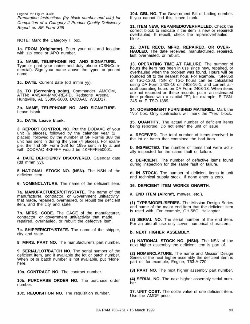
Legend for Figure 3-4B:Preparation Instructions (by block number and title) forCompletion of a Category II Product Quality DeficiencyReport on SF Form 368
NOTE: Mark the Category II box.
1a. FROM (Originator). Enter your unit and locationwith zip code or APO number.
1b. NAME, TELEPHONE NO. AND SIGNATURE.Type or print your name and duty phone (DSN/Com-mercial). Sign your name above the typed or printedname.
1c. DATE. Current date (dd mmm yy).
2a. TO (Screening point). Commander, AMCOM,ATTN: AMSAM-MMC-RE-FD, Redstone Arsenal,Huntsville, AL 35898-5000. DODAAC W81D17.
2b. NAME, TELEPHONE NO. AND SIGNATURE.Leave blank.
2c. DATE. Leave blank.
3. REPORT CONTROL NO. Put the DODAAC of yourunit (6 places), followed by the calendar year (2places), followed by the number of SF Forms 368 theunit has sent in during the year (4 places). For exam-ple, the first SF Form 368 for 1995 sent in by a unitwith DODAAC 4KFFFF would be 4KFFFF950001.
4. DATE DEFICIENCY DISCOVERED. Calendar date(dd mmm yy).
5 NATIONAL STOCK NO. (NSN). The NSN of thedeficient item.
6. NOMENCLATURE. The name of the deficient item.
7a. MANUFACTURER/CITY/STATE. The name of themanufacturer, contractor, or Government unit/activitythat made, repaired, overhauled, or rebuilt the deficientitem, and the city and state.
7b. MFRS. CODE. The CAGE of the manufacturer,contractor, or government unit/activity that made,repaired, overhauled, or rebuilt the defective item.
7c. SHIPPER/CITY/STATE. The name of the shipper,city and state.
8. MFRS. PART NO. The manufacturer’s part number.
9. SERIAL/LOT/BATCH NO. The serial number of thedeficient item, and if available the lot or batch number.When lot or batch number is not available, put "None"here.
10a. CONTRACT NO. The contract number.
10b. PURCHASE ORDER NO. The purchase ordernumber.
10c. REQUISITION NO. The requisition number.
10d. GBL NO. The Government Bill of Lading number.If you cannot find this, leave blank.
11. ITEM NEW, REPAIRED/OVERHAULED. Check thecorrect block to indicate if the item is new or repaired/overhauled. If rebuilt, check the repair/overhauledblock.
12. DATE RECD, MFRD, REPAIRED, OR OVER-HAULED. The date received, manufactured, repaired,last overhauled, or rebuilt.
13. OPERATING TIME AT FAILURE. The number ofhours the item has been in use since new, repaired, oroverhauled when the problem was found. Hours will berounded off to the nearest hour. For example, TSN-850or TSO-1203. TSN or TSO hours can be calculatedusing DA Form 2408-16 or 2408-16-1, and current air-craft operating hours on DA Form 2408-13. When itemsare not recorded on these records, put in an estimatedtime prefixed with a capital "E"; for example, E TSN-245 or E TSO-1889.
14. GOVERNMENT FURNISHED MATERIEL. Mark the"No" box. Only contractors will mark the "Yes" block.
15. QUANTITY. The actual number of deficient itemsbeing reported. Do not enter the unit of issue.
a. RECEIVED. The total number of items received inthe lot or batch that contained the bad item.
b. INSPECTED. The number of items that were actu-ally inspected for the same fault or failure.
c. DEFICIENT. The number of defective items foundduring inspection for the same fault or failure.
d. IN STOCK. The number of deficient items in unitand technical supply stock. If none enter a zero.
16. DEFICIENT ITEM WORKS ON/WITH.
a. END ITEM (Aircraft, mower, etc.).
(1) TYPE/MODEL/SERIES. The Mission Design Seriesand name of the major end item that the deficient itemis used with. For example, OH-58C, Helicopter.
(2) SERIAL NO. The serial number of the end item.For an aircraft use only seven numerical characters.
b. NEXT HIGHER ASSEMBLY.
(1) NATIONAL STOCK NO. (NSN). The NSN of thenext higher assembly the deficient item is part of.
(2) NOMENCLATURE. The name and Mission DesignSeries of the next higher assembly the deficient item ispart of; for example, Engine, T63-A-720.
(3) PART NO. The next higher assembly part number.
(4) SERIAL NO. The next higher assembly serial num-ber.
17. UNIT COST. The dollar value of one deficient item.Use the AMDF price.
93DA PAM 738–751 • 15 March 1999

18. ESTIMATED REPAIR COST. The estimated cost,including overhead, for fixing all deficient items in block15c. When you have more than one deficient item,multiply the cost to fix one item by the number of defi-cient items. If repair is not local, leave this block blank.
19a. ITEM UNDER WARRANTY. Check the block thatapplies.
19b. EXPIRATION DATE. The expiration date (ddmmm yy) of the warranty. Leave blank if it does notapply.
20. WORK UNIT CODE/EIC (Navy and Air Force On-ly). This block is also required for the Army. If thedeficient item is a reportable item enter the WUC of thedeficient item and the EIC of the aircraft or trainingdevice/simulator that the deficient item is installed on.WUC codes can be found in TB 1-1500-341-01 andEIC codes are listed in appendix D. If the item is not areportable item, just enter the EIC.
21. ACTION/DISPOSITION. Check one of the blocks toindicate the type of action taken. If an exhibit is held,indicate the number of days it will be held (the mini-mum is 55 days). If none of the items indicate theaction taken, check "OTHER." Then indicate the type ofaction taken in block 22.
22. DETAILS. Describe, to best ability, what is wrong,how and why, circumstances prior to difficulty, descrip-tion of difficulty, cause, action taken, including disposi-tion, recommendations. Attach copies of supportingdocuments. Continue on separate sheet if necessary.Enter the following information. Be sure to put theReport Control Number (block 3) on the continuationsheet.
a. UTILIZATION CODE. The proper code that identifiesthe type of unit or activity that found the fault or failure(see table 1-11).
b. WHEN FAULT WAS DISCOVERED. The proper"When Discovered Code" that applies to the fault, fail-ure or condition you are reporting. See table 1-4 or DAForm 2408, in the logbook for the proper code.
c. HOW RECOGNIZED. The proper "How RecognizedCode" that applies to the fault, failure, or condition youare reporting. See table 1-5 or DA Form 2408, in thelogbook for the proper code.
d. MALFUNCTION EFFECT ON MISSION. The proper"Malfunction Effect Code" that applies to the fault, fail-ure, or condition you are reporting when it affects themission in any way. See table 1-6 or DA Form 2408, inthe logbook for the proper code. If the fault, failure, orcondition did not affect the mission enter "2" No Effectcode.
e. TM NUMBER. To help identify the deficient item,enter the applicable TM number and date (dd mmmyy). Include the TM page, figure, and item number.
f. TOTAL AIRCRAFT HOURS. The total operatinghours of the deficient repair part, component/module, oraviation associated equipment. Round the operatinghours off to nearest hour. Get operating hours from the
current DA Form 2408-13, 2408-16, or 2408-16-1,which applies.
g. TIME SINCE INSTALLATION. The operating timesince installation of the defective item when it is differ-ent from item f, above.
h. FAILURE CODE. Enter the reason for the reporteddeficiency or failure by choosing the proper three digitcode from table 1-2 or 1-3; for example, 190 for Crack-ed.
i. CIRCUMSTANCES PRIOR TO DIFFICULTY. To aidin the investigation of the deficient item, enter all knowndetails about what happened, and conditions beforefailure of the item. Specify any modification or changesrecently applied that may be directly related to theproblem. When there is a structural fault or failure in anaircraft, enter the total gross weight of the aircraft.Enter conditions under which the fault or failure oc-curred; for example, takeoff, landing, acrobatic maneu-vers, hard landing. Enter any unusual circumstancesfound during previous flights or use; for example, thun-derstorm, hail, lightning. Include any information thatcould be the cause; for example, low power, hard land-ing. If you did any troubleshooting to locate the faultycomponent part or locate reason why the item failed,enter such information. If the deficient item is a compo-nent that calls for oil analysis, enter the date (dd mmmyy) the last oil analysis sample was taken. Identify thelab to which you sent the oil sample. Enter any otherinformation that will aid maintenance managers atAMCOM during maintenance and failure analysis of theitem reported.
j. DESCRIPTION OF DIFFICULTY. Include a brief, butcomplete description of the fault or failure. Refer torepair parts and assemblies by complete name andpart numbers. When you are referring to aircraft struc-tural components or assemblies, provide the stationnumber where the component or assembly is located.When the deficiency report is submitted because of aSFDLR initial failure, enter "INITIAL FAILURE CLAIM."
k. CAUSE. Outline the cause or probable cause foundduring your preliminary investigation.
l. ACTION TAKEN. Give a short summary of what youdid to correct the fault or problem to improve the itemreported. If the faulty item was fixed and put back inservice, describe the repair. Removal and replacementof the faulty item is not considered corrective action. Ifno action is taken to correct the fault or failure, print"None" here. If available send pictures, drawings, orsketches as attachments to the deficiency report. Whenthe deficiency report is prepared as a result of initialfailure of a SFDLR item, the LAR will enter "INITIALFAILURE--YES," his or her signature and date theyconcurred that it is an initial failure.
m. RECOMMENDATION. Give any suggestions to helpstop problems, improve the equipment, or changemaintenance instructions and procedures in technicalpublications.
NOTE: Sketches and pictures should be attached asneeded to help explain the condition and the equipmentimprovement recommendation.
94 DA PAM 738–751 • 15 March 1999

23. LOCATION OF DEFICIENT MATERIAL. The unitname, location, and zip code or APO number wherethe deficient materiel is located.
24a. THRU 27c. Filled out by AMCOM.
NOTE: If you do not wish to receive a reply to yourPQDR enter "SPO" in the bottom margin of the form.Use a red marker or pen to make this entry.
Figure 3-5. Sample of a completed DA Form 2408-13-3 (Aircraft Technical Inspection Worksheet) (Technical Inspection)
95DA PAM 738–751 • 15 March 1999

Figure 3-6. Sample of a completed DA Form 2408-13-3 (Aircraft Technical Inspection Worksheet) (Component Repair)
96 DA PAM 738–751 • 15 March 1999

Legend for Figure 3-6:Preparation Instructions (by block and title) for comple-tion of a DA Form 2408-13-3, Aircraft Technical Inspec-tion Worksheet
Page of . Enter the page number and totalnumber of pages.
1. ORGANIZATION. The name of the organizationdoing the inspection or repair.
2. MODEL. The item name and MDS. When this formis used to document in shop component repair, enterthe component/module, or repair part nomenclaturefrom DA Form 2407, block 9.
3. SERIAL NUMBER. The serial number of the itembeing inspected or repaired. If it is an aircraft useseven numerical characters. When this form is used todocument in shop component repair, enter the compo-nent/module, or repair part serial number from DAForm 2407, block 11.
4. TYPE INSPECTION. The type of inspection beingperformed. When this form is used to document inshop component repair, enter "Repair."
PART I--FAULT INFORMATION
STATUS. When the person, performing the technicalinspection, finds a fault or condition affecting the opera-tion or flight of the aircraft, training device/simulator, ormission related equipment, aboard the aircraft, they willrecord it in the FAULT INFORMATION block. Thenenter the proper status symbol in this block. Once astatus symbol is in the STATUS block, it will not beerased or changed even if in error (para 1-9). Theperson who corrects a red "dash" or red "diagonal" faultwill enter his or her last name initial over the statussymbol. A red "X" or circled red "X" status symbol willbe initialed over by a qualified designated representa-tive appointed by the unit/activity commander.
SYS. The system code that shows which system thefault is related to. (System Codes can be found on theDA Form 2408 in front of the logbook.)
DATE. The date (dd mmm yy) a fault is discovered, aremark is made, or an inspection is entered.
NO. Number of the fault, ULLS-A generated. Manualusers leave blank.
TIME. The time (24 hour clock) the fault was discov-ered.
PID. The person making the entry will enter their Per-sonnel Identifier.
FAULT/REMARKS. Enter remarks, faults ordeficiencies. Use as much space as needed to de-scribe the fault or deficiency.
ACFT HRS. The current aircraft flying hours at the timethe fault was discovered. Get the current aircraft flyinghours from the DA Form 2408-13. For AVIM or Depotin shop component repair, leave blank.
WHEN DISC. ULLS-A and LAS users must enter theappropriate When Discovered Code, for faults and dis-crepancies, from table 1-4 or DA Form 2408. Leaveblank when a remark is in the FAULT INFORMATIONBlock. Users under the manual record keeping systemmay use this block or leave it blank.
HOW REC. ULLS-A and LAS users must enter theappropriate How Recognized Code, for faults and dis-crepancies, from table 1-5 or DA Form 2408. Leaveblank when a remark is in the FAULT INFORMATIONBlock. Users under the manual record keeping systemmay use this block or leave it blank.
MAL EFF. ULLS-A and LAS users must enter the ap-propriate Malfunction Effect Code, for faults and dis-crepancies, from table 1-6 or DA Form 2408. Leaveblank when a remark is in the FAULT INFORMATIONBlock. Users under the manual record keeping systemmay use this block or leave it blank.
DELAY. Enter the Work Order Number, of the workrequest, to fix the fault or condition. Enter the SupplyRequisition Number for a repair part that is required torepair the fault. Enter "2408-13-2" when a DA From2408-13-2 is needed to list related maintenance actionsfor clearing the fault or deficiencies. If none, leaveblank.
WUC. ULLS-A and LAS users must enter the appropri-ate Work Unit Code, for faults and discrepancies. Forreportable components/modules, or parts the WUC canbe found in TB 1-1500-341-01. If a WUC has not beenestablished that applies to the component/module, orarea, enter the functional group code from table 1-10 orDA Form 2408 that best fits the fault or inspection.Leave blank when a remark is in the FAULT INFOR-MATION block. Users under the manual record keepingsystem may use this block or leave it blank.
PART II--CORRECTING INFORMATION.
DATE. The date (dd mmm yy) of the corrective action.
TIME. The time of day (24 hour clock) the correctiveaction was done.
ACFT HRS. The actual aircraft hours when the correc-tive action was completed.
ROUNDS. For armament system faults, discrepancies,and inspections, for which a DA Form 2408-4-1 ismaintained, enter the cumulative rounds fired from DAForm 2408-4-1, block 5e.
ACTION CODE. For ULLS-A and LAS users, enter themaintenance action code, from table 1-9 or DA Form2408, which best describes the action taken. Usersunder the manual record keeping system may use thisblock or leave it blank.
WUC. For ULLS-A and LAS users enter the Work UnitCode that best describes which component/module orpart the corrective action pertains to. If a WUC has notbeen established for the component/module, part orarea, enter the functional group code from table 1-10 orDA Form 2408 that best fits corrective action. The cor-rective action WUC may be different from the WUC in
97DA PAM 738–751 • 15 March 1999

the FAULT INFORMATION block. Users under themanual record keeping system may use this block orleave it blank.
ACTION. Enter an abbreviated explanation of the ac-tion taken, for example, "Replaced rotor blade." Thewords "replaced," "repaired," "adjusted," or "erroneousentry," with other brief information about the action, willbe enough to describe the action taken. DO NOT usethe word "corrected" on this or any form.
PID. The personnel identifier of the person(s) ac-complishing all or part of the maintenance action.
CAT. ULLS-A and LAS users shall enter the categoryof maintenance for the action taken -- "C" for crewlevel, "O" for AVUM level, "F" for AVIM level, or "D" forDepot level. When DA Form 2408-13-3, dated NOV 91,is used the category will be entered in the HOURSblock preceding the man-hours expended by each indi-vidual who corrected the fault. If an individual performsboth crew level and AVUM level work to perform thecorrective action, they will enter their PID twice, once
for crew and once for AVUM level maintenance hours.Users under the manual record keeping system mayuse this block or leave it blank.
HRS. ULLS-A and LAS users shall enter the direct"hands on" man-hours, in hours and tenths, expendedduring actual maintenance. Users under the manual re-cord keeping system may use this block or leave itblank.
NOTE: When DA Form 2408-13-3, dated NOV 91, isused, the CMH, OMH, FMS, and DMH blocks will beleft blank.
TIPID. The personnel identifier of the technical inspec-tor who inspected the maintenance action.
TI MAN-HOURS. ULLS-A and LAS shall enter theirman-hours, in hours and tenths, it took to inspect theaction taken, and to complete the forms and records.Users under the manual record keeping system mayuse this block or leave it blank.
98 DA PAM 738–751 • 15 March 1999

Figure 3-7. Sample of a completed DA Form 2405, Maintenance Request Register
Legend for Figure 3-7:Preparation Instructions (by block and title) for comple-tion of a DA Form 2405 (Maintenance Request Regis-ter)
a. JOB ORDER NUMBER. The WON from the DAForm 2407, or the Control Number from the DA Form2410.
b. QUANTITY AND NOMENCLATURE. The quantityand item name from DA Form 2407, or DA Form 2410.You can list only one item for each organization WONwhen this form is used for DA Form 2407.
c. WORK REQUESTED BY. The name of the unit oractivity asking for the work. Get this information fromDA Form 2407, block 1b.
d. SERIAL OR USA REGISTRATION NUMBER. Theitem serial number. Use seven numerical digits for air-craft serial number.
e. BRIEF DESCRIPTION OF WORK OR REMARKS.The fault or the action to be taken. Action includesrepair, MWO to be applied, one time inspection, and soon.
f. DATE JOB ORDER RECEIVED. Enter the juliandate the request was submitted.
g. DATE REPAIR STARTED. Enter the julian date therepair or other action started.
h. DATE REPAIR FINISHED. Enter the julian date therepair or other action was completed.
i. MAN-HOURS. Enter the total number of man-hours,in hours and tenths, it took to do the repair or otheraction.
j. LABOR. Leave blank or use as required locally.
99DA PAM 738–751 • 15 March 1999

k. PARTS. Leave blank or use as required locally. l. TOTAL COST OF JOB. Leave blank or use as re-quired locally.
Figure 3-8. Sample of a completed DA Form 2407 to request support maintenance.
100 DA PAM 738–751 • 15 March 1999

Legend for Figure 3-8:Preparation Instructions (by block and title) for Comple-tion of a DA Form 2407 (Maintenance Request) to Re-quest Support Maintenance
NOTE: For SAMS Units, blocks 1, 5, 6, 7, 10a, 11, 12,13, 15, 16, and 24 are mandatory if equipment is inop-erable. Inoperable equipment is equipment that isNMC, according to AR 700-138, a subsystem of areportable weapon system, or a command maintenancesignificant item.
PAGE NO. Enter the page number. A "1" if this is thefirst page.
NO OF PAGES. Leave this block blank.
SECTION I--CUSTOMER DATA
1a. UIC CUSTOMER. The UIC of the unit/organizationthat owns the aircraft, component/module or equipment.
1b. CUSTOMER UNIT NAME. The name of the unit in1a.
1c. PHONE NO. The phone number (DSN/Commercial)of the unit in 1a.
2a. SAMS-2 UIC/SAMS-1/TDA. If intransit enter theowning unit’s UIC. Units not using SAMS, leave blank.
2b. UTILIZATION CODE. The appropriate UtilizationCode from table 1-11.
2c. MCSR. Print the word "YES" or the letter "Y" if theitem is reported under AR 700-138. This also applies tocomponents and subsystems of an item or system thatis reportable. If not reportable under AR 700-138 leaveblank.
SECTION II--MAINTENANCE ACTIVITY DATA.
NOTE: To be completed by support maintenance AVIMor Depot.
SECTION III--EQUIPMENT DATA.
5. TYPE MNT REQ. The appropriate Type Mainte-nance Request Code from table 1-16. Units not usingSAMS leave blank.
6. ID. The Identification Code that identifies the type ofnumber you will enter in block 7--
A -- National/NATO Stock Number.
C -- Manufacter’s Code and Reference Number (PartNumber).
D -- Management Control Number (MCN).
P -- Other Numbers
7. NSN. The National Stock Number or appropriatenumber identified in block 6.
8. MODEL. The Mission Design Series of the equip-ment needing support maintenance.
9. NOUN. The name of the item needing support main-tenance.
10a. ORG WON/DOC NO. The organization work ordernumber or organization document number. For assign-ment of ORG WON for SAMS units, see paragraph 3-11. Units not using the SAMS system may assign alocal WON. The local WON will be composed of 12digits. The first six characters will be the owning unit oractivity UIC, followed by the two digit year, and a fourdigit number for number of DA Forms 2407 submittedin numerical order.
10b. EIC. The End Item Code that applies to yourequipment, see table D-1.
11. SERIAL NUMBER. The Serial Number of the itemin block 9. If the form is used for more than one item,leave blank.
12. QTY. The number of items. Only one item will belisted if equipment is reportable under AR 700-138 andis NMC.
13. PD. The Priority Designator, see DA Pamphlet 710-2-1.
14. MALFUNCTION DESCRIPTION (for DSU, GSU/AVIM, DEPOT use). To be used by AVIM and Depot.
15a. FAILURE DETECTED DURING/WHEN DISCOV-ERED CODE. The appropriate When Discovered Codefrom table 1-4.
15b. FIRST INDICATION OF TROUBLE/HOW REC-OGNIZED CODE. The appropriate How RecognizedCode from table 1-5.
16. MILES/KILOMETERS/HOURS/ROUNDS.
Miles -- Leave blank.
Kilometers -- Leave blank.
Hours -- For aircraft enter the aircraft hours from thecurrent DA Form 2408-13. For components/modulesand assemblies, enter the time since new as calculatedfrom the DA Form 2408-16, or total cumulative operat-ing hours calculated from DA Form 2408-16-1. If theitem in block 9 is not an aircraft or is not listed in TB 1-1500-341-01, leave blank.
Rounds -- If a weapon system or weapon system sub-component is entered in block 9, enter the total cumu-lative number of rounds fired. Get this information fromthe DA Form 2408-4-1 for the weapon system.
If the weapon system does not have a DA Form 2408-4-1, leave blank. If this form is prepared for an AH-64helicopter, enter the total cumulative rounds firedagainst the airframe from the current DA Form 2408-12
101DA PAM 738–751 • 15 March 1999

or DA Form 2408-13. Leave blank when it does notapply.
17. PROJECT CODE. SAMS Units enter the assignedProject Code. If none is assigned, leave blank. Unitsnot using SAMS may leave blank.
18. ACCOUNT PROCESSING CODE. The AccountProcessing Code (APC) if required by your unit, other-wise leave blank. The APC is a code prescribed locallyfor costing and budget identification of customers andorganizations (reference TM 38-711-13).
19. IN WARRANTY? Enter "Y" or "N" to indicatewhether equipment is still under manufacturer’s warran-ty. If "Y," submit one work request for each serial num-bered item. If unknown leave blank.
20. ADMIN NUMBER. For aircraft and aviationcomponents/modules, leave blank.
21. REIMBURSABLE CUSTOMER. For AVIM and De-pot use.
22. LEVEL OF WORK. The code for the maintenancelevel of the activity doing the work --
O -- Aviation Unit Maintenance (AVUM).
F -- Aviation Intermediate Maintenance (AVIM).
D -- Depot.
K -- Contractor.
L -- Special Repair Activity.
23. SIGNATURE. The commander or his or her desig-nated representative will sign for all priority 01 through10 requests. This signature approves the use of thePD.
24. DESCRIBE DEFICIENCIES OR SYMPTOMS ONTHE BASIS OF COMPLETE CHECKOUT AND DIAG-NOSTIC PROCEDURES IN EQUIPMENT TM.
a. Briefly describe the fault or failure and give symp-toms. When possible, use information from DA Forms2408-13-1, 2408-13-2, 2408-13-3, or 2408-14-1. Do notask for general or specific repairs, or for parts to be
replaced. For example, do not tell support to "Replacethe engine" or "Repair as needed."
b. When the form is asking for work on more than oneitem with the same NSN, list the number of items andtheir serial numbers (if they have serial numbers).Equipment, components/modules, or subsystems ofreportable equipment, or command maintenance signifi-cant equipment reported on the Material Condition Sta-tus Report must have its own separate form.
c. When the form is requesting standard repair after abattle-damage expedient has been applied, print"BDAR" in bold letters before describing the fault orsymptoms.
d. If you need more room, use a DA Form 2407-1.
25. REMARKS. Enter any remarks that may assist theAVIM or Depot in repair of the item.
a. When the form is prepared for components/modulesor assemblies with a recoverability code of A, D, F, H,or L, list the end item NSN on the last line. Therecoverability codes can be found in the RC Code col-umn of the AMDF and as part of the item’s Source,Maintenance, and Recoverability (SMR) code in theparts manual.
b. Indicate any historical forms sent with the compo-nent/module or aircraft.
34a. SUBMITTED BY. First name initial and last nameof the person preparing the form.
34b. DATE. The date (yyddd) the form was given tosupport.
35a. ACCEPTED BY. First name initial and last nameof the person accepting the work request.
35b. STATUS. The person accepting the request willenter the work request status code. Table 1-17 liststhese codes.
35c. DATE. The date (yyddd) the request is accepted.
35d. TIME. The military time the request is accepted.
102 DA PAM 738–751 • 15 March 1999

Figure 3-9. Sample of a completed DA Form 2407 to show work done at support maintenance
103DA PAM 738–751 • 15 March 1999

Legend for Figure 3-9:Preparation Instructions (by block number and title) forCompletion of a DA Form 2407 (Maintenance Request)to Show Work Done at AVIM and Depot Support Main-tenance
PAGE NO. Already filled in by the unit requesting thesupport maintenance.
NO OF PAGES. The total number of pages required tocomplete the maintenance actions.
REQUIREMENT CONTROL SYMBOL. Leave blank.
SECTION I--CUSTOMER DATA. Already filled in bythe unit requesting the support maintenance.
SECTION II--MAINTENANCE ACTIVITY DATA.
3a. WORK ORDER NUMBER (WON). Units under theSAMS system will enter the WON assigned by the sup-port unit. Units not using the SAMS system may assigna local WON (see subpara 3-11c)
3b. SHOP. The shop section code assigned to identifya particular maintenance shop. Codes A through Z areassigned locally by each maintenance battalion operat-ing under the SAMS system. Example: A = AvionicsShop, B = Battery Shop, E = Engine Shop, and so on.Units not using the SAMS system may leave blank.
3c. PHONE NO. The phone number (DSN/Commercial)of the maintenance activity doing the work.
4a. UIC SUPPORT UNIT. The Unit Identification Codeof the maintenance activity.
4b. SUPPORT UNIT NAME. The unit name of themaintenance activity.
SECTION III--EQUIPMENT DATA.
5 THROUGH 13. Already filled in by the unit requestingthe support maintenance.
14. MALFUNCTION DESCRIPTION (for DSU, GSU/AVIM, DEPOT use). A short description of the problem(16 position entry).
15 THROUGH 20. Already filled in by the unit request-ing the support maintenance.
21. REIMBURSABLE CUSTOMER (if Transit cus-tomer enter Y or N). Enter "Y" if the customer mustpay the maintenance cost.
22 THROUGH 24. Already filled in by the unit request-ing the support maintenance.
25. REMARKS.
a. When the item in block 7 needs on site or deferredmaintenance, the AVIM or Depot activity will enter oneof the following statements:
(1) Maintenance Request received on (date), on site
maintenance scheduled for (date), signature of Produc-tion Control NCO.
(2) Maintenance Request received on (date) deferred,owner to return item on (date) for repair.
(3) Print "ORF" when an Operational Readiness Floatwas issued or would have been issued if a serviceableORF asset was available.
b. For aviation night vision goggles, the AVIM unit willenter the new intensifier tube serial numbers whenevermaintenance is performed to replace the tubes.
NOTE: The Receipt Copy 1 will be retained at theAVIM or Depot activity. The owning unit keeps all othercopies until the on site repair is started or the deferreditem is taken back to support.
26. TECHNICAL REFERENCES. The reference TM ortechnical publication as needed. Enter a statement ofthe partial mission capable (PMC) condition when itapplies.
SECTION IV--TASK REQUIREMENTS DATA.
NOTE: This section of the work order can be used invarious ways by the support maintenance activity: onetask repair action for the work order, one task for eachcenter/shop section that is to work on the equipment,or a task for each repair action necessary can be re-corded. The general rule for task management is toallow the capturing of man-hours expended on equip-ment. The task sequence number is not to be confusedwith work request status code changes.
27a. FILE INPUT ACT CD. Units using the SAMS sys-tem enter the File Input Action Code. For example, A =Addition of a new record file, C = Correction to the filerecords, D = Deletion of the record from the file. Unitsnot using the SAMS system may leave blank.
27b. TASK NO. The Task Number. Units not using theSAMS system may leave blank. How to use this field isup to the support maintenance activity of units usingthe SAMS system. At least one character (letter ornumber) must be used and task numbers must be dif-ferent for each task listed. Some of the various waysthis field can be used are as follows:
a. A single task for all work needed to be done (forexample, task number 1).
b. A task for each work center/shop section for workneeded to be done at each work center/shop section.The task number can be the shop section code.
c. A task for each action specified to be done by in-spectors. The task number can then be the characterfor the shop followed by a different number for eachtask. For example, tasks A1, A2, and A3 may be usedfor the Avionics Shop and tasks S1 and S2 for theSheetmetal Shop, and so on.
104 DA PAM 738–751 • 15 March 1999

27c. ACT CODE. The appropriate Action Code fromtable 1-9.
27d. TASK DESCRIPTION. Brief description of task tobe accomplished.
27e. QTY TO BE RPR. Number of items to berepaired.
27f. WORK CENTER. The Work Center Code of theshop that will do the task (see Unit SOP).
27g. FAILURE CODE. The appropriate Failure Codefrom tables 1-2 and 1-3.
27h. MH PROJ. The number of man-hours projected toaccomplish the task.
27i. MH EXP. The number of man-hours actually ex-pended to accomplish the task.
SECTION V--PART REQUIREMENTS
28a. FILE INPUT ACT CD. The File Input Action Code.Same as 27a.
28b. TASK NO. The Task Number that generated theparts requirement.
28c. ID NO. The Identifying Number that identifies thetype of information in the NSN field.
A -- National Stock Number.
C -- Manufacturer’s Code and Reference Number.
D -- Management Control Number.
P -- Other Numbers.
28d. NSN OR PART NUMBER. The National StockNumber, Manufacturer’s Part Number, or other number,as identified in block 28c for the required part.
28e. SFX CD. Units not using the SAMS system mayleave blank. Units using the SAMS system, will enterthe Suffix Identification Code when applicable. Thiscode allows the operator to use the same record key(that is, WOG, Task Number, Identification Code, andNSN), when adding the same NSN to a file. It enablesthe operator to bypass edits that normally would rejectas being duplicate. Each new entry should be in se-quential order. Blank, A-Z, 0-9 are the allowed entries.
28f. QTY RQD. The quantity of part(s) needed.
28g. QTY ISSUED. The quantity of part(s) issued tothe mechanic.
28h. NMCS CD. If failure to get a part will cause theitem to become NMCS, enter "Y." If item will not be-come NMCS, enter "N."
28i. FAILURE CODE. The Failure Code from tables 1-2 and 1-3 that best describes why the item failed.
28j. STORAGE LOCATION. Units not using the SAMS
system may leave blank. Units using the SAMS systemwill enter the Storage Location Code, if it is a SSL item(see unit SOP).
28k. INITIALS. Units not using the SAMS system mayleave blank. Units using the SAMS system will enterthe initials of the SSL clerk releasing the part to themechanic.
28l. COST $. Units not using the SAMS system mayleave blank. Units using the SAMS system will enterthe total cost of the part(s). Multiply 28g by the AMDFunit price.
28m. TOTAL MAN-HOURS. Add the Man-hours Ex-pended in block 27i, on all pages of DA Forms 2407and 2407-1, to get the total man-hours.
28n. TOTAL MAN-HOURS COSTS $. Multiply block28m, Total Man-hours, by the current local labor ratefor total man-hour costs. Units not using the SAMSsystem may leave blank.
28o. TOTAL PARTS COSTS $. Add the parts cost inblock 28l, on all pages of DA Forms 2407 and 2407-1,to get the total parts costs. Units not using the SAMSsystem may leave blank.
SECTION VI--COMPLETION DATA
29. QTY RPR. The number of items repaired.
30. QTY CONDEMN. The number of items condemned.
31. QTY NRTS. The number of items not reparable atthis activity.
32. EVAC WON. The WON assigned by the receivingmaintenance unit if the item is evacuated.
33. EVAC UNIT NAME. The name of the unit to whichthe item is evacuated.
SECTION VII--ACTION SIGNATURES
34a and 34b. Already filled in.
35a. ACCEPTED BY. The first name initial and lastname of the person accepting the work request.
35b. STATUS. The appropriate work request statuscode from table 1-17.
35c. DATE. The date (yyddd) that the work order wasaccepted.
35d. TIME. The military time that the work order wasaccepted.
36a. WORK STARTED BY. The first name initial andlast name of the person starting the work.
36b. STATUS. The appropriate work request statuscode from table 1-17.
105DA PAM 738–751 • 15 March 1999

36c. DATE. The date (yyddd) the work was started.
36d. TIME. The military time the work was started.
37a. INSPECTED BY. The first name initial and lastname of the commander or designated representativeinspecting the work.
37b. STATUS. The appropriate status from table 1-17.
37c. DATE. The date (yyddd) the inspection was com-pleted.
37d. TIME. The military time the inspection was com-pleted.
38a. PICKED UP BY. The first name initial and lastname of the person picking up the equipment.
38b. STATUS. The support maintenance clerk entersthe work request status code "U" (Picked Up).
38c. DATE. The date (yyddd) the equipment was pi-cked up.
38d. TIME. The military time the equipment was pickedup.
Preparation Instructions (by block and title) for Comple-tion of a DA Form 2407-1 (Maintenance Request--Con-tinuation Sheet) to Record Maintenance Work at AVIMand Depot Support Maintenance.
NOTE: This form is used when more space is neededon the DA Form 2407. It can also be used to list partsand to control components in support maintenance ac-tivities.
PAGE NO. The page number.
NO OF PAGES. The total number of pages used (DAForms 2407 and 2407-1).
REQUIREMENT CONTROL SYMBOL. The controlnumber from the DA Form 2407. If there is no controlnumber on the DA Form 2407, enter the WON from theDA Form 2407.
SECTION II--MAINTENANCE ACTIVITY DATA
3a. WORK ORDER NUMBER (WON). The WON fromblock 3a of the DA Form 2407.
3b. SHOP SECTION CODE. The shop section codeassigned to identify a particular maintenance shop sec-tion. Codes A through Z are assigned locally by eachmaintenance battalion operating under the SAMS sys-tem. Units not using the SAMS system may leaveblank.
3c. PHONE NO. The phone number (DSN/Commercial)from block 3c of the DA Form 2407.
SECTION III--EQUIPMENT DATA25a. REMARKS. Use as a continuation to block 25 ofthe DA Form 2407 as needed, or prescribed locally.
NOTE: Fill in the following sections and blocks accord-ing to the instructions for the DA Form 2407.
SECTION IV--TASK REQUIREMENTS DATA (blocks27a through 27i)
SECTION V--PART REQUIREMENTS (blocks 28athrough 28o)
106 DA PAM 738–751 • 15 March 1999

Figure 3-10. Sample of a completed DA Form 2407 to request application of an MWO
107DA PAM 738–751 • 15 March 1999

Legend for Figure 3-10:Preparation Instructions (by block and title) for Comple-tion of a DA Form 2407 (Maintenance Request) to Re-quest Application of an MWO.
PAGE NO. Enter the page number.
NO OF PAGES. Leave this block blank.
SECTION I--CUSTOMER DATA
1a. UIC CUSTOMER. The UIC of the unit/organizationthat owns the aircraft, component/module or equipmentto be modified.
1b. CUSTOMER UNIT NAME. The name of the unit in1a.
1c. PHONE NO. The phone number (DSN/Commercial)of the unit in 1a.
2a. SAMS-2 UIC/SAMS-1/TDA. If intransit enter theowning unit’s UIC. Units not using SAMS, leave blank.
2b. UTILIZATION CODE. The appropriate UtilizationCode from table 1-11.
2c. MCSR. Print the word "YES" or the letter "Y" if theitem is reported under AR 700-138. This also applies tocomponents and subsystems of an item/system that isreportable. If not reportable under AR 700-138 leaveblank.
SECTION II--MAINTENANCE ACTIVITY DATA.
NOTE: To be completed by support maintenance AVIMor Depot.
SECTION III--EQUIPMENT DATA.
5. TYPE MNT REQ. The appropriate Type Mainte-nance Request Code from table 1-18. Units not usingthe SAMS system may leave blank.
6. ID. The Identification Code that identifies the type ofnumber you will enter in block 7--
A -- National/NATO Stock Number.
C -- Manufacter’s Code and Reference Number (PartNumber).
D -- Management Control Number (MCN).
P -- Other Numbers
7. NSN. The National Stock Number or appropriatenumber identified in block 6.
8. MODEL. The Mission Design Series of the equip-ment needing the MWO.
9. NOUN. The name of the item needing the MWO.
10a. ORG WON/DOC NO. The organization work ordernumber or organization document number. For assign-ment of ORG WON for SAMS units (see para 3-11).Units not using the SAMS system may assign a localWON. The local WON will be composed of 12 digits.The first six characters will be the owning unit or activ-ity UIC, followed by the two digit year, and a four digitnumber for number of DA Forms 2407 submitted innumerical order.
10b. EIC. The appropriate End Item Code that appliesto your equipment, from appendix D-1.
11. SERIAL NUMBER. The Serial Number of the itemin block 9. If the form is used for more than one item,leave blank.
12. QTY. The number of items being modified. Onlyone item will be listed if equipment is reportable underAR 700-138 and is NMC.
13. PD. The Priority Designator, see DA Pamphlet 710-2-1.
14. MALFUNCTION DESCRIPTION (for DSU, GSU/AVIM, DEPOT use). Leave blank.
15a. FAILURE DETECTED DURING/WHEN DISCOV-ERED CODE. Leave blank.
15b. FIRST INDICATION OF TROUBLE/HOW REC-OGNIZED CODE. Leave blank.
16. MILES/KILOMETERS/HOURS/ROUNDS.
Miles -- Leave blank.
Kilometers -- Leave blank.
Hours -- For aircraft enter the aircraft hours from thecurrent DA Form 2408-13. For components/modulesand assemblies, enter the time since new as calculatedfrom the DA Form 2408-16 or total cumulative operat-ing hours calculated from DA Form 2408-16-1. If theitem in block 9 is not an aircraft or is not listed in TB 1-1500-341-01, leave blank.
Rounds -- If a weapon system or weapon system subcomponent is in block 9, enter the total cumulativenumber of rounds fired. Get this information from theDA Form 2408-4-1 for the weapon system. If theweapon system does not have a DA Form 2408-4-1,leave blank. If this form is prepared for an AH-64 heli-copter, enter the total cumulative rounds fired againstthe airframe from the current DA Form 2408-12 or2408-13. Leave blank when it does not apply.
17. PROJECT CODE. SAMS Units enter the assignedProject Code. If none is assigned, leave blank. Unitsnot using SAMS may leave blank.
18. ACCOUNT PROCESSING CODE. The AccountProcessing Code (APC) if required by your unit, other-wise leave blank. The APC is a code prescribed locallyfor costing and budget identification of customers andorganizations (reference TM 38-711-13).
19. IN WARRANTY? Leave blank.
108 DA PAM 738–751 • 15 March 1999

20. ADMIN NUMBER. For aircraft and aviation compo-nents/modules, leave blank.
21. REIMBURSABLE CUSTOMER. For AVIM and De-pot use.
22. LEVEL OF WORK. The code for the maintenancelevel of the activity doing the work-
O -- Aviation Unit Maintenance (AVUM).
F -- Aviation Intermediate Maintenance (AVIM).
D -- Depot
23. SIGNATURE. The commander or his or her desig-nated representative will sign for all priority 01 through10 requests. This signature approves the use of thePD.
24. DESCRIBE DEFICIENCIES OR SYMPTOMS ONTHE BASIS OF COMPLETE CHECKOUT AND DIAG-NOSTIC PROCEDURES IN EQUIPMENT TM.
a. Enter the MWO number(s). If more than one MWOis listed, make sure all the MWOs apply to each com-ponent or end item covered by the form.
b. When asking to have the MWOs applied to compo-nents, list the component’s end item NSN.
c. Items and components of items listed in AR 700-138cannot be combined on one form. Make out a separateDA Form 2407 for those items needing MWOs.
d. Components/modules listed in TB 1-1500-341-01,also require a separate DA Form 2407.
e. If you need more room, use a DA Form 2407-1.
25. REMARKS.
a. When a MWO is applied to components or assem-blies, list the component, assembly, and item NSN.
b. List the Procurement Request Order Number(PRON), the Fiscal Station Number, and the MFP orMOU identification number.
c. Indicate any historical forms sent with the compo-nent/module or aircraft.
34a. SUBMITTED BY. The first name initial and lastname of the person preparing the form.
34b. DATE. The date (yyddd) the form was given tosupport.
35a. ACCEPTED BY. The first name initial and lastname of the person accepting the work request.
35b. STATUS. The person accepting the request willenter the work request status code. Table 1-17 liststhese codes.
35c. DATE. The date (yyddd) the request is accepted.
35d. TIME. The military time the request is accepted.
109DA PAM 738–751 • 15 March 1999
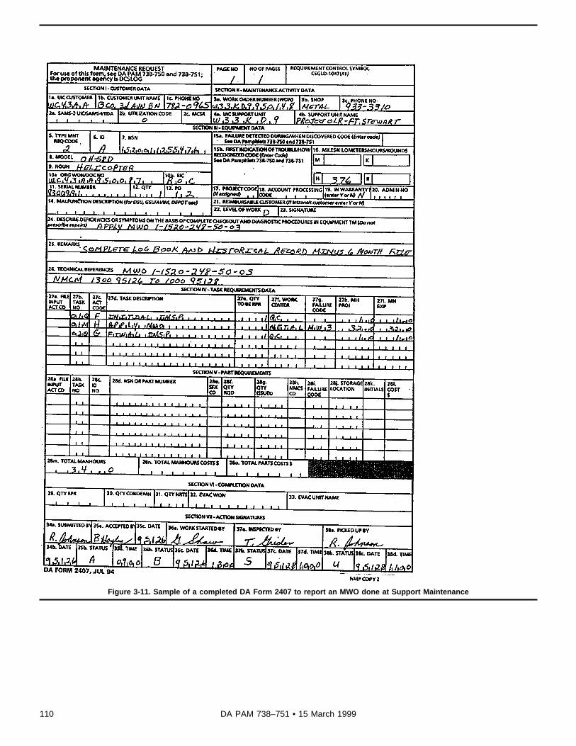
Figure 3-11. Sample of a completed DA Form 2407 to report an MWO done at Support Maintenance
110 DA PAM 738–751 • 15 March 1999

Legend for Figure 3-11:Preparation Instructions (by block number and title) forCompletion of a DA Form 2407 (Maintenance Request)to Report MWO Application at Support Maintenance
PAGE NO. Already filled in by the unit requesting theMWO application.
NO OF PAGES. The total number of pages required tocomplete the maintenance actions.
REQUIREMENT CONTROL SYMBOL. Leave blank.
SECTION I--CUSTOMER DATA. Already filled in bythe unit requesting the MWO application.
SECTION II--MAINTENANCE ACTIVITY DATA.
3a. WORK ORDER NUMBER (WON). Units under theSAMS system will enter the WON assigned by the sup-port unit. Units not using the SAMS system may assigna local WON (see subpara 3-11c).
3b. SHOP. The shop section code assigned to identifya particular maintenance shop. Codes A through Z areassigned locally by each maintenance battalion operat-ing under the SAMS system. Example: A = AvionicsShop, B = Battery Shop, E = Engine Shop, and so on.Units not using the SAMS system may leave blank.
3c. PHONE NO. The phone number (DSN/Commercial)of the maintenance activity applying the MWO.
4a. UIC SUPPORT UNIT. The Unit Identification Codeof the maintenance activity applying the MWO.
4b. SUPPORT UNIT NAME. The unit name of themaintenance activity applying the MWO.
SECTION III--EQUIPMENT DATA.
5 THROUGH 13. Already filled in by the unit requestingthe MWO application.
14. MALFUNCTION DESCRIPTION (for DSU, GSU/AVIM, DEPOT use). Leave blank.
15 THROUGH 20. Already filled in by the unit request-ing the MWO application.
21. REIMBURSABLE CUSTOMER (if Intransit cus-tomer enter Y or N). Enter "Y" if the customer mustpay the maintenance cost.
22 THROUGH 24. Already filled in by the unit request-ing the MWO application.
25. REMARKS.
a. When the item in block 7 needs on site or deferredmaintenance, the AVIM or Depot activity will enter oneof the following statement: "Maintenance Request re-ceived on (date), on site maintenance scheduled for
(date), or owner to return item for modification on(date)."
b. Use as needed locally or as prescribed by SOP.
NOTE: The Receipt Copy 1 will be retained at theAVIM or Depot activity. The owning unit keeps all othercopies until the on site repair is started or the deferreditem is taken back to support.
26. TECHNICAL REFERENCES.
a. The reference TM or technical publication asneeded.
b. Record NMCS, NMCM, and FMC/PMC times (inhours). The start and end time and dates (yyddd) foreach NMC and NMCM period must be recorded.
SECTION IV--TASK REQUIREMENTS DATA.
27a. FILE INPUT ACT CD. Units using the SAMS sys-tem enter the File Input Action Code. For example, A =Addition of a new record file, C = Correction to the filerecords, D = Deletion of the record from the file. Unitsnot using the SAMS system may leave blank.
27b. TASK NO. Leave blank.
27c. ACT CODE. The Action Code "H" for the MWOapplication and "G" for the final inspection of the appli-cation (see table 1-9).
27d. TASK DESCRIPTION.
a. Enter the ID and NSN of the item getting the MWO.When the MWO changes the item’s NSN, list the oldNSN.
b. Directly below the ID and NSN enter the MWO num-ber.
c. When applying one MWO to several items with thesame NSN, list the MWO once, but list the NSNs onseparate lines. Use DA Form 2407-1 if more space isrequired.
d. When applying more than one MWO to an item, listthe MWOs in numerical order.
NOTE: When a component/module listed in TB 1-1500-341-01 changes NSN, Part Number, and/or SerialNumber due to a MWO, DA Forms 2410 must be sub-mitted losing the old NSN, Part Number, and/or SerialNumber. Update DA Forms 2408-5, 2408-5-1, 2408-16or 2408-16-1 as necessary to reflect the MWO andchanged data.
27e. QTY TO BE RPR. Number of items to be modi-fied.
27f. WORK CENTER. Enter MIL when military person-nel apply the MWO, CIV when civilians do the work, orCONTR when contractors do the work.
27g. FAILURE CODE. Enter the appropriate FailureCode --
111DA PAM 738–751 • 15 March 1999

a. 797 -- MWO previously complied with.
b. 798 -- MWO not applicable.
c. 801 -- MWO compliance.
d. 802 -- Equipment previously modified/restored tooriginal configuration (MWO removal).
27h. MH PROJ. Enter the number of man-hours proj-ected to accomplish the task.
27i. MH EXP. Enter the number of man-hours actuallyexpended to accomplish the task.
a. Break the man-hours out by civilian, to include con-tractor or contractor field team, and military.
b. If the MWO was previously applied and you do notknow the actual hours, enter the estimated man-hoursfrom the MWO publication.
SECTION V--PART REQUIREMENTS
NOTE: If no extra work is done during application,leave this section blank or use as needed locally. Ifwork is completed along with the MWO application,complete blocks 28a through 28l.
28a. FILE INPUT ACT CD. The File Input Action Code.Same as 27a.
28b. TASK NO. The Task Number that generated theparts requirement. Units not using the SAMS systemmay leave blank.
28c. ID NO. The Identifying Number that identifies thetype of information in the NSN field.
A -- National Stock Number.
C -- Manufacturer’s Code and Reference Number.
D -- Management Control Number.
P -- Other Numbers.
28d. NSN OR PART NUMBER. The National StockNumber, Manufacturer’s Part Number, or other number,as identified in block 28c for the item modified.
28e. SFX CD. Units not using the SAMS system mayleave blank. Units using the SAMS system, will enterthe Suffix Identification Code when applicable. Thiscode allows the operator to use the same record key(that is, WOG, Task Number, Identification Code, andNSN), when adding the same NSN to a file. It enablesthe operator to bypass edits that normally would rejectas being duplicate. Each new entry should be in se-quential order. Blank, A-Z, 0-9 are the allowed entries.
28f. QTY RQD. The quantity of part(s) needed.
28g. QTY ISSUED. The quantity of part(s) issued tothe mechanic.
28h. NMCS CD. If failure to get a part will cause the
item to become NMCS, enter "Y." If item will not be-come NMCS, enter "N."
28i. FAILURE CODE. The Failure Code from tables 1-2 and 1-3 that best describes why the item failed.
28j. STORAGE LOCATION. Units not using the SAMSsystem may leave blank. Units using the SAMS systemwill enter the Storage Location Code, if it is a SSL item(see unit SOP).
28k. INITIALS. Units not using the SAMS system mayleave blank. Units using the SAMS system will enterthe initials of the SSL clerk releasing the part to themechanic.
28l. COST $. Units not using the SAMS system mayleave blank. Units using the SAMS system will enterthe total cost of the part(s). Multiple 28g by the AMDFunit price.
28m. TOTAL MAN-HOURS. Add the Man-hours Ex-pended in block 27i, on all pages of DA Forms 2407and 2407-1, to get the total man-hours.
28n. TOTAL MAN-HOURS COSTS $. Multiply block28m, Total Man-hours, by the current local labor ratefor total man-hour costs. Units not using the SAMSsystem may leave blank.
28o. TOTAL PARTS COSTS $. Add the parts cost inblock 28l, on all pages of DA Forms 2407 and 2407-1,to get the total parts costs. Units not using the SAMSsystem may leave blank.
SECTION VI--COMPLETION DATA
NOTE: If no extra work is done during modification thissection may be left blank or use as needed locally.
29. QTY RPR. The number of items repaired.
30. QTY CONDEMN. The number of items condemned.
31. QTY NRTS. The number of items not repairable atthis activity.
32. EVAC WON. The WON assigned by the receivingmaintenance unit if the item is evacuated.
33. EVAC UNIT NAME. The name of the unit to whomthe item is evacuated.
SECTION VII--ACTION SIGNATURES
34a and 34b. Already filled in.
35a. ACCEPTED BY. The first name initial and lastname of the person accepting the work modificationrequest.
35b. STATUS. The appropriate work request statuscode from table 1-17.
35c. DATE. The date (yyddd) that the work requestwas accepted.
112 DA PAM 738–751 • 15 March 1999

35d. TIME. The military time that the work request wasaccepted.
36a. WORK STARTED BY. The first name initial andlast name of the person assigned the job of applyingthe MWO.
36b. STATUS. The appropriate work request statuscode from table 1-17.
36c. DATE. The date (yyddd) the work was started.
36d. TIME. The military time the work was started.
37a. INSPECTED BY.
a. When MWOs are applied by an ARMY maintenanceactivity, a technical inspector assigned will monitor theapplication, make a final inspection, and sign his or herfirst name initial and last name.
b. When MWOs are applied by a contractor, the con-tracting officer’s representative will monitor the applica-tion, make a final inspection, and sign his or her first
name initial and last name. The person clearing thework enters his or her first name initial and last name.
c. When MWOs are applied by a contract field team,the AMCOM NMP representative will monitor the appli-cation, make a final inspection, and sign his or her firstname initial and last name.
37b. STATUS. The appropriate status from table 1-17.
37c. DATE. The date (yyddd) the inspection was com-pleted.
37d. TIME. The military time the inspection was com-pleted.
38a. PICKED UP BY. The first name initial and lastname of the person picking up the equipment.
38b. STATUS. The support maintenance clerk entersthe work request status code "U" (Picked Up).
38c. DATE. The date (yyddd) the equipment was pi-cked up.
38d. TIME. The military time the equipment was pickedup.
Figure 3-12. Sample of a completed page of a phase maintenance checklist.
113DA PAM 738–751 • 15 March 1999

Legend for Figure 3-12:Preparation Instructions (by block title) for Completionof Phase, PMS, or Periodic Maintenance Checklist
PHASE (PMS OR PERIODIC) NO. The Phase, PMS,Periodic Inspection number.
Area Name and No. Preprinted.
Aircraft Serial No. The aircraft Serial Number (sevennumeric digits).
Date. The date (dd mmm yy) the checklist page wasmade out.
Inspect Phase No’s. Preprinted.
Inspection Requirements. Preprinted.
Status. Leave blank.
Faults and/or Remarks. If aircraft, repair part, compo-nent, or system disassembly is required to complete aninspection requirement enter "DA Form 2408-13-2," andthe page number of the form. If a fault or discrepancy
is found enter "DA Form 2408-13-1" or "DA Form 2408-13-3," and the page number of the form. No otherentries will be made in this block.
Action Taken. When no faults or deficiencies are dis-covered, the person completing each inspection re-quirement task/seq. no. will enter "Insp OK." Whenfaults or deficiencies are discovered, the person whofound the fault or deficiency will enter "Insp Compl."For units maintaining forms and records manually, if aDA Form 2408-18 inspection requirement is listed asthe Inspection Task enter "Completed" or "Compl" andthe date of completion. Then update the date due onthe DA Form 2408-18. For units under ULLS-A or LAS,if a DA Form 2408-18 inspection requirement is listedas the Inspection Task enter "Insp Compl" and enterthe DA Form 2408-18 inspection on a DA Form 2408-13-1, if not already printed on the DA Form 2408-13-1,for completion. When the Inspection Task does not ap-ply to the aircraft, as equipped, or to the phase beingcompleted, enter "N/A."
Initial. The person who completes the inspection taskor determines the task is N/A will enter his or her PIDopposite the first line of the Action Taken entry.
114 DA PAM 738–751 • 15 March 1999

Figure 3-13. Sample of a completed DA Form 2408-13-2 used to document disassembly to complete an inspection requirement duringphase maintenance
Legend for Figure 3-13:Preparation Instructions (by block number and title) forCompletion of a DA Form 2408-13-2 (Related Mainte-nance Actions Record) when Documenting Disassemb-ly, to Complete an Inspection Task, in conjunction withthe Maintenance Inspection Checklist.
DATE. The date (dd mmm yy) the form was made out.
PAGE. Forms used as a supplement to an inspectionTask will be inserted into the Inspection Checklist andnumbered as a supplement to the checklist. For exam-ple, a DA Form 2408-13-2 is required to documentrelated maintenance actions for an area or task onPage 3-2 of the maintenance checklist, the page num-ber of the form would be 3-2a, another DA Form 2408-13-2 attached to that page would be numbered 3-2b.
NOTE: DA Forms 2408-13-2 used to document related
maintenance actions for correction of faults or deficien-cies entered on a DA Form 2408-13-1 will become partof the Flight Pack and numbered as part of the FlightPack.
1. STATUS. Leave blank.
2. SERIAL NUMBER. The aircraft Serial Number(seven numeric digitis).
3. SYSTEM CODE. Leave blank.
4. TIME. Leave blank.
5. FAULT DATE. Leave blank.
6. FAULT NUMBER. Leave blank.
115DA PAM 738–751 • 15 March 1999

7. FAULT. The Phase, Periodic, or PPM Inspectionnumber and area sequence number.
8. STA. The proper condition status symbol, accordingto the seriousness of each related maintenance actionin block 9 (see para 1-8).
9. RELATED MAINTENANCE ACTIONS. A short de-scription of the related maintenance actions needed tocomplete the inspection area listed in block 7. Enteronly one related maintenance action on each line pro-vided. Use as many lines and forms as needed to enterrelated maintenance actions to complete the inspectionarea.
10. ACTION. The action taken to complete the relatedmaintenance action.
11. PID. The personnel identifier of the person complet-ing the related maintenance action. They will also placetheir last name initial over the status symbol in block 8.
A red "X" or circled red "X," must be inspected by adesignated representative appointed by the command-er. If the action taken is satisfactory, enter the inspec-tor’s stamp or statement "Insp OK" and signatureabove the corrective action in block 10. The inspectorwill then place his or her last name initial over thestatus symbol.
NOTE: If the inspector discovers other fault(s), recordthem on the next open Fault Information block on theDA Form 2408-13-1 or 2408-13-3. ULLS-A or LAS us-ers must enter the faults on a DA Form 2408-13-1.
12. CAT. The level of maintenance for the action taken("C" for crew level, "O" for AVUM level, "F" for AVIMlevel, or "D" for Depot level).
13. MMH. Units that use ULLS-A or LAS will enter theman-hours it took to complete the action. All other unitsmay leave blank.
116 DA PAM 738–751 • 15 March 1999

Figure 3-14A. Sample of a completed DA Form 2410 for gain to the Army inventory. (Illustration #1)
117DA PAM 738–751 • 15 March 1999
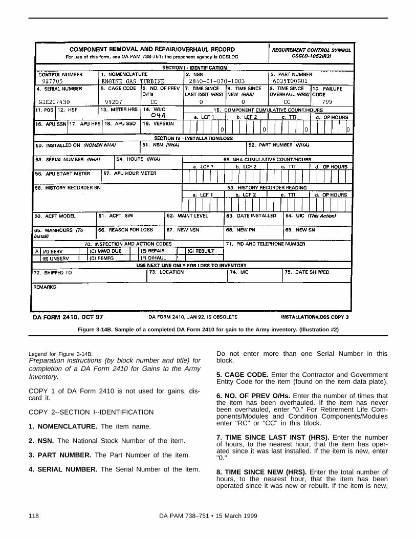
Figure 3-14B. Sample of a completed DA Form 2410 for gain to the Army inventory. (Illustration #2)
Legend for Figure 3-14B:Preparation instructions (by block number and title) forcompletion of a DA Form 2410 for Gains to the ArmyInventory.
COPY 1 of DA Form 2410 is not used for gains, dis-card it.
COPY 2--SECTION I--IDENTIFICATION
1. NOMENCLATURE. The item name.
2. NSN. The National Stock Number of the item.
3. PART NUMBER. The Part Number of the item.
4. SERIAL NUMBER. The Serial Number of the item.
Do not enter more than one Serial Number in thisblock.
5. CAGE CODE. Enter the Contractor and GovernmentEntity Code for the item (found on the item data plate).
6. NO. OF PREV O/Hs. Enter the number of times thatthe item has been overhauled. If the item has neverbeen overhauled, enter "0." For Retirement Life Com-ponents/Modules and Condition Components/Modulesenter "RC" or "CC" in this block.
7. TIME SINCE LAST INST (HRS). Enter the numberof hours, to the nearest hour, that the item has oper-ated since it was last installed. If the item is new, enter"0."
8. TIME SINCE NEW (HRS). Enter the total number ofhours, to the nearest hour, that the item has beenoperated since it was new or rebuilt. If the item is new,
118 DA PAM 738–751 • 15 March 1999

or has just been rebuilt, enter "0." For H-60 seriesAPUs without an installed hour meter enter "0."
9. TIME SINCE OVERHAUL (HRS). If the item hasbeen overhauled before, enter the number of hours, tothe nearest hour, that the item has operated since thelast overhaul. If the item has never been overhauledenter "0." If the item is a RC or CC item, enter "RC" or"CC." For H-60 series APUs, enter "0".
10. FAILURE CODE. For new items enter "799." Forother items enter the appropriate failure code fromtables 1-2 or 1-3.
11. POS. Leave blank.
12. HSF. For T703 engines, enter the total hot sectionfactors.
13. METER HRS. Enter the hourmeter reading foritems designated by TB 1-1500-341-01 to be trackedusing meter hours.
14. WUC. Enter the work unit code that applies.
15. COMPONENT CUMULATIVE COUNT/HOURS. ForT700 series engines, components/modules, and sub-components enter the total cumulative counts/hours forthe item in block 1. This entry is also required forhistory recorders. Enter only operating hours, block15.d., for components/modules, entered on the reverseside of the engine DA Form 2408-16-1, that do notrequire a separate DA Form 2408-16-1. If the item isnew enter "0."
15a. LCF 1. For T700 series engines, components/modules, or subcomponents enter the total cumulativeLCF1 counts.
15b. LCF 2. For T700 series engines, components/modules, or subcomponents enter the total cumulativeLCF 2 counts.
15c. TTI. For T700 series engines, components/mod-ules, or subcomponents enter the total cumulative TTIcounts.
15d. OP HOURS. For T700 series engines, compo-nents/modules, or subcomponents enter the total cumu-lative operating hours.
16. APU SSN. For H-60 series aircraft APUs enter thetotal starts since new. If the APU is new enter "0."
17. APU HRS. For H-60 series aircraft APUs with aninstalled hour meter, enter the total hours since new forthe APU. If the APU is new enter "0."
18. APU SSO. For H-60 series aircraft APUs, enter the
number of starts since the last overhaul. If the APU isnew or has never been overhauled, enter "0."
19. VERSION. Enter the software version for the itementered in block 1 when required by TB 1-1500-341-01.
COPY 2--SECTION III--REPAIR/OVERHAUL/GAIN.
NOTE: Leave blocks 20 through 34 blank.
39. DATE CHECKED. Enter the Julian date that theitem, in block 1, was declared serviceable by the man-ufacturer/contractor or the Julian date the item was ac-cepted in the Army inventory by the receiving unit.
40. PID AND TELEPHONE NUMBER. Enter thesignature, PID and telephone number of the manufac-turer’s/contractor’s representative declaring the itemserviceable. Army units receiving items without DAForm 2410 will fill out the forms and enter their PIDand phone number (DSN/Commercial).
41. UIC (THIS ACTION). Enter the Unit IdentificationCode for the organization taking this action. If a con-tractor, enter the CAGE code prefixed with a "K."
42. MAN-HOURS TO REPAIR/OVERHAUL. Leaveblank.
43. INSPECTION AND ACTION CODES. Enter an "A"in the small block in front of "(A) SERV" for serviceableitems, or the appropriate letter in other blocks as itapplies. Do not use check marks.
44. REASON FOR GAIN. Enter "A" for new manufac-tured items, or other codes from table 1-14 that bestdescribes the reason for gain.
45. CONTRACT NUMBER. Enter the contract numberthat the item in block 1 was procured under. Use thisblock for "A" gains only.
NOTE: Leave blocks 46 through 48 blank.
REMARKS. Provide any information not consideredroutine.
COPY 3--SECTION IV--INSTALLATION/LOSS.
70. INSPECTION AND ACTION CODES. Enter "A"infront of "(A) SERV" for serviceable items, or the appro-priate letter in other block as it applies. Do not usecheck marks.
NOTE: Mail Copy 2 to AMCOM. Copy 3 remains withthe component/module until installation.
119DA PAM 738–751 • 15 March 1999

Figure 3-15. Sample of a completed DA Form 2410 for the normal removal, evacuation, repair, and installation cycle. (Removal an dEvacuation)
Legend for Figure 3-15:Preparation Instructions (by block number and title) forcompletion of a DA Form 2410 for the normal removal,evacuation, repair, and installation cycle. (Removal andEvacuation).
COPY 1--SECTION I-IDENTIFICATION
1. NOMENCLATURE. The item name.
2. NSN. The National Stock Number of the item.
3. PART NUMBER. The Part Number of the item.
4. SERIAL NUMBER. The Serial Number of the item.Do not enter more than one Serial Number in thisblock.
5. CAGE CODE. The Contractor and Government En-tity Code for the item, (found on the item data plate).
6. NO. OF PREV O/Hs. Enter the number of times thatthe item has been overhauled. Get this informationfrom block 6d of the DA Form 2408-16 or block 6a ofDA Form 2408-16-1 for H-60 series aircraft APUs. Ifthe item has never been overhauled, enter "0." ForRetirement Life Components and Condition Compo-nents enter "RC" or "CC" in this block.
7. TIME SINCE LAST INSTL (HRS). Enter the numberof hours, to the nearest hour, the item has been oper-ated since it was last installed. Get this informationfrom DA Form 2408-16 by subtracting block 6e from 6f.For T700 series engines get this information from theDA Form 2408-16-1 by subtracting the total cumulativehours at installation from the total cumulative hours atremoval. For H-60 series APUs get this information
120 DA PAM 738–751 • 15 March 1999

from the DA Form 2408-16-1. For H-60 series APUswithout an installed hour meter enter "0."
8. TIME SINCE NEW (HRS). Enter the total number ofhours, to the nearest hour, that the item has beenoperated since it was new or rebuilt. Get this informa-tion from block 6i of the DA Form 2408-16. For T700series engines get this information from the DA Form2408-16-1. For H-60 series APUs with an installed hourmeter, enter the total hours since new. For H-60 seriesAPUs without an installed hour meter enter "0."
9. TIME SINCE OVERHAUL (HRS). If the item hasbeen overhauled before, enter the number of hours, tothe nearest hour, that the item has operated since thelast overhaul. Get this information from the DA Form2408-16; subtract block 6e from 6f, then add block 6g.When the item has never been overhauled, enter "0." Ifthe item is a RC or CC item, enter "RC" or "CC."
10. FAILURE CODE. Enter the appropriate FailureCode (Tables 1-2 and 1-3).
11. POS. Enter the position that the engine was in-stalled in, number 1 for left engine and number 2 forright engine.
12. HSF. For T703 engines, enter the total number ofhot section factors.
13. METER HRS. Enter the hourmeter reading foritems designated by TB 1-1500-341-01 to be trackedusing meter hours.
14. WUC. Enter the work unit code that applies.
15. COMPONENT CUMULATIVE COUNT/HOURS. ForT700 series engines, components/modules, and subcomponents enter the total cumulative counts/hours forthe item in block 1. This entry is also required forhistory recorders. Enter only operating hours, block15.d., for components/modules, entered on the reverseside of the engine DA Form 2408-16-1, that do notrequire a separate DA Form 2408-16-1. If the item isnew enter "0."
15a. LCF 1. For T700 series engines, components/modules, or subcomponents enter the total cumulativeLCF 1 counts.
15b. LCF 2. For T700 series engines, components/modules, or subcomponents enter the total cumulativeLCF 2 counts.
15c. TTI. For T700 series engines, components/mod-ules, or subcomponents enter the total cumulative TTIcounts.
15d. OP HOURS. For T700 series engines, compo-nents/modules, or subcomponents enter the total cumu-lative operating hours.
16. APU SSN. For H-60 series aircraft APUs enter thetotal starts since new. If the APU is new enter "0".
17. APU HRS. For H-60 series aircraft APUs with aninstalled hour meter, enter the total hours since new forthe APU. If the APU is new enter "0".
18. APU SSO. For H-60 series aircraft APUs, enter thenumber of starts since the last overhaul. If the APU isnew or has never been overhauled, enter "0". .
19. VERSION. Enter the software version for the itementered in block 1 when required by TB 1-1500-341-01.
COPY 1--SECTION II--REMOVAL DATA
This section is completed by the organization that re-moved the reportable item from its next higher assem-bly.
NOTE: Blocks 20 through 23 will be left blank if thenext higher assembly is an aircraft.
20. REMOVED FROM (NOMEN NHA). The name ofthe next higher assembly, from which the item in block1 was removed. This information is on the DA Form2408-16, block 1, or DA Form 2408-16-1, block 3.
21. NSN (NHA). The National Stock Number of theitem in block 20.
22. PART NUMBER (NHA). The Part Number of theitem in block 20.
23. SERIAL NUMBER (NHA). The Serial Number ofthe item in block 20.
24. HOURS (NHA). The current aircraft hours, to thenearest hour, if the next higher assembly is an aircraft.When the item, in block 20, is a component, enter thecomponents operating hours since new.
25. NHA CUMULATIVE COUNTS/HOURS. Enter thetotal cumulative counts and hours since new for theT700 series engine, component or module entered inblock 20. Obtain the total cumulative counts from theDA Form 2408-16-1 for the item. If a T700 series en-gine, component or module is not entered in block 20,leave blank.
26. APU START METER. For H-60 series aircraft enterthe reading from the APU start meter at the time ofAPU removal. If the APU does not have a start meter,leave blank.
27. APU HOUR METER. For H-60 series aircraft enterthe reading from the APU hour meter at the time ofAPU removal. If the APU does not have a hour meter,leave blank.
28. HISTORY RECORDER S/N. If a T700 series en-gine is entered in block 1 or block 20, enter the enginehistory recorder serial number. Leave blank if a historyrecorder is not used. Do not enter a history recorderserial number from a slave engine used for componentor module testing. For H-60 series APUs leave blank.
29. HISTORY RECORDER READING. If a T700 seriesengine is entered in block 1 or block 20, enter thecurrent reading from the engine history recorder.
30. ACFT MODEL. The aircraft Mission Design Series
121DA PAM 738–751 • 15 March 1999

if the next higher assembly is an aircraft, otherwiseleave blank.
31. ACFT S/N. The aircraft Serial Number if the nexthigher assembly is an aircraft, otherwise leave blank.
32. MAINT LEVEL. The Maintenance Level ("O" forAVUM, "F" for AVIM, "D" for Depot) of the unit/activitydoing the removal.
33. DATE REMOVED. The Julian date that the removalaction was completed.
34. UIC. The Unit Identification Code for the organiza-tion taking this action. If a contractor, enter the CAGEcode prefixed with a "K."
35. MAN-HOURS (To Remove). The man-hours it tookto remove the item, in hours and tenths. (See TimeConversion Codes, table 1-12, at the end of chapter 1or the backside of DA Form 2408.)
36. PID AND TELEPHONE NUMBER. The individualcompleting the form will enter his or her PID and phone
number (DSN/Commercial). The phone number andPID will be used at the national level to clarify entries.
37. MALFUNCTION CODE. The Malfunction EffectCode (table 1-6 or the front side of DA Form 2408) thatmost closely described the effect the malfunction hadon the mission.
38. WHEN DISCOVERED. The When Discovered Code(Table 1-4 or the front side of DA Form 2408) thatidentifies when the failure was first detected.
REMARKS. If a "Corrected Copy" indicate the blocknumbers that were corrected. If the total cumulativecounts and hours on a T700 series engine or module/component were calculated due to history recorder fail-ure make an entry stating all pertinent information.Make this entry in the remarks block of copy 2 also.
NOTE: Provide any information that may be helpful tothe higher level maintenance activity to repair the item,to include location of leaks, breakage, or suspectedreason for the fault in the REMARKS block on Copy 2.Complete information can save time and dollars. MailCopy 1 to AMCOM. Copies 2 and 3 are shipped withthe item.
122 DA PAM 738–751 • 15 March 1999

Figure 3-16. Sample of a completed DA Form 2410 for normal removal, evacuation, repair, and installation cycle (Repair/Overhaul )
Legend for Figure 3-16:Preparation Instructions (by block number and title) forcompletion of a DA Form 2410 for Normal Removal,Evacuation, Repair, and Installation Cycle (Repair/Overhaul).
COPY 2--SECTION III--REPAIR/OVERHAUL/GAIN
This section appears on the lower half of Copy 2.Blocks 1 through 34 should already be filled in. Entriesin this section, as well as block 70 of Copy 3, are filledin by the organization that returns the item to a service-able condition. This organization will also update blocks6, 7, 8, 9, 10, 12, 15, 16, 17, 18, 19, 43, and 70, asnecessary, by lining out existing entries and providingthe correct data. For T703 engines, after completion ofrepair/overhaul line out the HSF counts in block 12 ofcopies 2 and 3 and enter the updated HSF counts. Therepair facility will also make an entry, in block 7 of the
engine DA Form 2408-16, showing the HSF countsafter repair/overhaul. After repair, to ensure serviceabili-ty, the cumulative counts/hours must be updated onT700 series engine components/modules, or sub com-ponents that have operated on a slave engine. Calcu-late the LCF 1, LCF 2, TTI, and OP HOURSaccumulated while operating on the slave engine andadd to the counts/hours in block 15. Line out the oldcounts and hours and enter the updated counts andhours in block 15. Update the time since new in block8. Make sure that all blocks that were updated on Copy2 are updated on Copy 3. The DA Form 2408-16-1,line 1, must also be updated.
39. DATE CHECKED. The Julian date that the actionshown in block 43 was completed.
40. PID AND TELEPHONE NUMBER. The personcompleting the form will sign and enter his or her PID,
123DA PAM 738–751 • 15 March 1999

and phone number (DSN/Commercial). The phonenumber and PID will be used to clarify entries.
41. UIC (THIS ACTION). The Unit Identification Codeof the organization that completed the action shown inblock 43. If a contractor, enter the CAGE code prefixwith a "K."
42. MAN-HOURS TO REPAIR/OVERHAUL. The totalman-hours, in hours and tenths, it took to repair/over-haul, or rebuild the item (see Time Conversion chart,table 1-12, at the end of chapter 1 or the backside ofDA Form 2408).
43. INSPECTION AND ACTION CODES. If the item isfound serviceable enter "A" in the small block next to(A) SERV. When an unserviceable item is returned toserviceable status enter "D" for (REMFG), "E" for(REPAIR), "F" for (O/HAUL), or "G" for (REBUILT) inthe block that applies. Do not use check marks. Do notenter "F" for Overhaul if the entries in blocks 6 and 9are RC or CC.
44. REASON FOR GAIN. Leave blank.
45. CONTRACT NUMBER. Leave blank.
46. MAINT LEVEL. Enter the level of the maintenance
("O" for AVUM, "F" for AVIM, "D" for Depot) of theactivity performing the action indicated in block 36.
47. ACTUAL FAILURE CODE. Block 10 of this formidentifies the apparent failure code at time of removal.Upon further disassembly and exploration, the rootcause for failure may be different from that observed attime of removal. The overhaul/repair facility will enterthe actual failure code in this block. See table 1-2 or 1-3 at the end of chapter 1 for the failure code.
48. SRA/ESRA. If the item in block 1 was repairedusing a special repair authorization from AMCOM orthe item was repaired by an Enhanced Special RepairActivity enter "Y," all others enter "N."
REMARKS. Provide brief pertinent remarks for the ac-tion checked in block 43.
NOTE: After repair/overhaul, rebuild, or inspection linethrough the failure code in block 10, Copy 2 and 3 andenter "799." After all entries are completed on Copy 2,front and backside, mail to AMCOM. Update block 70of Copy 3 by entering "A" in the small block next to (A)SERV. Make sure that all other blocks are updated onCopy 3 and ship with the serviceable component/mod-ule. When a countermeasure set AN/ALQ-144 isrepaired, enter all items replaced during the repair onthe reverse of copy 2.
124 DA PAM 738–751 • 15 March 1999

Figure 3-17. Sample of a completed DA Form 2410. Reverse of copy #2.
Legend for Figure 3-17:Preparation Instructions (by block number and title) forcompletion of a DA Form 2410, Reverse Side of Copy2.
REVERSE SIDE OF COPY 2--PARTS REPLACEDDURING REPAIR/OVERHAUL. The reverse side ofCopy 2 is used to list repair parts replaced duringrepair, overhaul, or rebuild of the item in block 1. It willbe completed by the maintenance activity including de-pot level maintenance, organic, or contractor supportthat completes the maintenance. When repair partswith serial numbers are reported, parts will be listedindividually as a quantity of 1. All parts used exceptcommon, bulk issued hardware will be listed as follows:
49a. FAIL CODE. The failure code that best describes
why the item was removed and replaced (see table 1-2or 1-3).
49b. QTY. The total quantity for each part.
49c. ACT. The correct Maintenance Action Code, suchas "A" for replaced, "B" for adjusted, "C" for repaired(nonserialized) (see table 1-9).
49d. NOMENCLATURE. The name of the part.
49e. PART NUMBER. The manufacturer’s Part Num-ber.
49f. SERIAL NUMBER. The Serial Number for eachpart removed. If the part does not have a serial num-ber, leave blank.
49g. CUMULATIVE COUNTS/HOURS LAST DEPOT
125DA PAM 738–751 • 15 March 1999

REPAIR. For T700 series engines enter the total cumu-lative counts upon removal of repair parts from theengine or major components/modules. The counts andoperating hours can be found on the DA Form 2408-
16-1. For H-60 series APUs, enter the number of prioroverhauls in the LCF 1 block, starts since overhaul inthe LCF 2 block, starts since new in the TTI block, andtotal operating hours since new for the repair part orsubcomponent.
Figure 3-18. Sample of a completed DA Form 2410 for the Normal Evacuation Repair and Installation Cycle, (Installation)
Legend for Figure 3-18:Preparation Instructions (by block number and title) forcompletion of a DA Form 2410 for the Normal Evacua-tion, Repair and Installation Cycle, (Installation).
COPY 3--SECTION I--IDENTIFICATION
NOTE: Blocks 1 through 19 and block 70 should al-ready be filled in. When installing an engine on amultiengine aircraft line out the position number in
block 11 and enter the new position number, number 1for left engine or number 2 for right engine.
COPY 3--SECTION IV--INSTALLATION/LOSS
NOTE: Blocks 50 through 53 will be left blank if thenext higher assembly is an aircraft.
50. INSTALLED ON (NOMEN NHA). The name of thenext higher assembly on which the reportable item isinstalled.
126 DA PAM 738–751 • 15 March 1999

51. NSN (NHA). The NSN of the item in block 50.
52. PART NUMBER (NHA). The Part Number of theitem in block 50.
53. SERIAL NUMBER (NHA). The Serial Number ofthe item in block 50.
54. HOURS (NHA). The current aircraft hours, to thenearest hour, if the next higher assembly is an aircraft.If item is a component, enter the operating hours, tothe nearest hour, since new or rebuild.
55. NHA CUMULATIVE COUNTS/HOURS. Enter thetotal cumulative counts and hours since new for theT700 series engine, component or module entered inblock 50. Obtain the total cumulative counts from theDA Form 2408-16-1 for the item. If a T700 series en-gine, component or module is not entered in block 50,leave blank.
56. APU START METER. For H-60 series aircraft enterthe reading from the APU start meter at the time ofAPU installation. If the APU does not have a start me-ter, leave blank.
57. APU HOUR METER. For H-60 series aircraft enterthe reading from the APU hour meter at the time ofAPU installation. If the APU does not have a hour me-ter, leave blank.
58. HISTORY RECORDER S/N. If a T700 series en-gine is entered in block 1 or block 50, enter the enginehistory recorder serial number. Leave blank if a historyrecorder is not used. Do not enter a history recorderserial number from a slave engine used for componentor module testing.
59. HISTORY RECORDER READING. If a T700 seriesengine is entered in block 1 or block 50, enter thecurrent reading from the engine history recorder.
60. ACFT MODEL. The Mission Design Series of the
aircraft. Leave blank if block 50 is an engine, APU, orcomponent/module.
61. ACFT S/N. The aircraft Serial Number if the nexthigher assembly is an aircraft, otherwise leave blank.
62. MAINT LEVEL. The maintenance level ("O" forAVUM, "F" for AVIM, or "D" for Depot) performing theaction.
63. DATE INSTALLED. The Julian date that the report-able item was installed.
64. UIC (THIS ACTION). The Unit Identification Codeof the organization doing the installation. If a contractor,enter the CAGE code prefixed with a "K."
65. MAN-HOURS (TO INSTALL). The man-hours, inhours and tenths, it took to install the item in block 1.
66. REASON FOR LOSS. Leave blank.
67. NEW NSN. Leave blank.
68. NEW PN. Leave blank.
69. NEW SN. Leave blank.
70. INSPECTION AND ACTION CODES. No action re-quired.
71. PID AND TELEPHONE NUMBER. The individualcompleting the form will enter his or her PID and phonenumber (DSN/Commercial). The phone number andPID will be used at the national level to clarify entries.
Blocks 72 through 75. Leave blank.
NOTE: Mail this copy to AMCOM.
127DA PAM 738–751 • 15 March 1999

Figure 3-19. Sample of a completed DA Form 2410 for change from serviceable to unserviceable uninstalled items. (Installation)
Legend for Figure 3-19:Preparation Instructions (by block number and title) forcompletion of a DA Form 2410 for Changes from Serv-iceable to Unserviceable Uninstalled Items.
COPY 3--SECTION I--IDENTIFICATION
NOTE: Update blocks 10 and 70 of the DA Form 2410to show the current status.
COPY 3--SECTION IV--INSTALLATION/LOSS
Blocks 50 through 62. Leave blank.
63. DATE INSTALLED. The Julian date that the itemwas determined to be unserviceable.
64. UIC (THIS ACTION). The Unit Identification Codefor the activity that has the item listed in block 1. If acontractor enter the CAGE code prefixed with a "K."
BLOCKS 65 through 69. Leave blank.
70. INSPECTION AND ACTION CODES. If the changein serviceability status resulted from the publication ofan MWO, or other directive enter "C" in the small boxin front of the (C) MWO DUE Block. If the serviceabilitystatus changed because of damage, enter "B" in thesmall box in front of the (B) UNSERV Block, also oblit-erate entries in other blocks. If the "B" and "C" codesboth apply, or an MWO or other directive includes anNSN, P/N, and/or S/N change, enter only the "C" codein the box in front of the (C) MWO DUE Block, andfollow procedures in figures 3-27 and 3-28.
128 DA PAM 738–751 • 15 March 1999

71. PID AND TELEPHONE NUMBER. The personcompleting the form will enter his or her PID and tele-phone number (DSN/Commercial).
BLOCKS 72 through 75. Leave blank.
NOTE: Mail Copy 3 to AMCOM. Initiate a new DAForm 2410 using the data on the old copy 3. Do notchange the control number of the new form. Copy 1destroy. Copies 2 and 3 will have blocks 1 thru 15 filledin and will remain with the unserviceable item. Enterany additional information that could be helpful in therepair of the item, or the cause of the damage on Copy2, REMARKS block.
Figure 3-20A. Sample of a completed DA Form 2410 for an NSN/PN/serial number change for an uninstalled item. (Illustration #1)
129DA PAM 738–751 • 15 March 1999

Figure 3-20B. Sample of a completed DA Form 2410 for an NSN/PN/serial number change of an uninstalled item. (Illustration #2)
Legend for Figure 3-20B:Preparation Instructions (by block number and title) forcompletion of DA Form 2410 for an NSN/PN/SNChange of an Uninstalled Item.
NOTE: Discard Copy 2 of the original or existing DAForm 2410.
COPY 3--SECTION I--IDENTIFICATION
Blocks 1 through 19. Already filled in.
COPY 3--SECTION IV--INSTALLATION/LOSS
BLOCKS 50 through 62. Leave blank.
63. DATE INSTALLED. Enter the Julian date the actionis completed.
64. UIC (THIS ACTION). The Unit Identification Codefor the activity that determined the NSN/PN/SN is to bechanged. If a contractor enters the Cage code prefixedwith a "K."
65. MANHOURS TO INSTALL. Leave blank.
66. REASON FOR LOSS. Enter "M."
67. NEW NSN. Enter the new NSN that the item willhave after modification. If the NSN will not change,leave blank.
68. NEW PN. Enter the new part number that the itemwill have after modification. If the part number will notchange, leave blank.
130 DA PAM 738–751 • 15 March 1999

69. NEW SN. Enter the new serial number that theitem will have after modification. If the serial numberwill not change, leave blank.
70. INSPECTION AND ACTION CODES. Enter a "C"in the box in front of the (C) MWO DUE Block. Line outany other entries in block 39.
71. PID AND TELEPHONE NUMBER. The personcompleting this form will enter his or her PID, and tele-phone number (DSN/Commercial).
BLOCKS 72 through 75. Leave blank.
NOTE: Line out entry in block 10 and enter "801."When Copy 3 is completed, start a new DA Form 2410(see figure 3-19, illustration #1). Destroy new copy 1.Do not change the control number of the new form.
COPY 2--SECTION I--IDENTIFICATION
Complete block 1 and blocks 5 through 19 by copyingthis information from the old copy 3.
2. NSN. The new National Stock Number (block 67 ofthe old copy 3) if the NSN was changed by an MWO orother directive. If the NSN was not changed, enter theNSN from block 2, of the old copy 3.
3. PART NUMBER. The new Part Number (block 68,of the old copy 3) if the PN was changed by an MWOor other directive. If the PN was not changed, enter thePN from block 3, of the old copy 3.
4. SERIAL NUMBER. The new Serial Number (block69 of the old copy 3) if the SN was changed by anMWO or other directive. If the SN was not changed,enter the SN from block 4 of the old copy 3.
COPY 2--SECTION III--REPAIR/OVERHAUL/GAINDATA
Blocks 20 through 34. Leave blank.
39. DATE CHECKED. The Julian date the repair ormaintenance action was completed.
40. PID AND TELEPHONE NUMBER. The personcompleting this form will enter his or her PID and tele-phone number (DSN/Commercial) in this block.
41. UIC. The Unit Identification Code for the activitythat performed the work. If a contractor enter theCAGE code prefixed with a "K."
42. MAN-HOURS TO REPAIR/OVERHAUL. The totalman-hours, in hours and tenths, it took to do the work.
43. INSPECTION AND ACTION CODES. Place theproper letter in the small box next to the action codethat applies. Do not use check marks. Do not enter "F"for Overhaul if the entries in blocks 6 and 9 are RC orCC.
44. REASON FOR GAIN. After the MWO or other di-rective is applied, enter "S."
45. CONTRACT NUMBER. Leave blank.
46. MAINT LEVEL. The maintenance level ("O" forAVUM, "F" for AVIM, or "D" for depot) of the unit doingthe MWO or other directive.
47. ACTUAL FAILURE CODE. Enter "801."
48. SRA/ESRA. If the item in block 1 was repairedusing a special repair authorization from AMCOM orthe item was repaired by an Enhanced Special RepairActivity enter "Y," all others enter "N".
NOTE: Update blocks 6 through 19, and REMARKSwhen needed on Copies 2 and 3. Update block 70 ofCopy 3 by entering "A" in the small block next to (A)SERV. Copy 3 remains with the component/module un-til installation. Attach Copy 1 and 2 to the old Copy 3and mail to AMCOM.
131DA PAM 738–751 • 15 March 1999

Figure 3-21A. Sample of a completed DA Form 2410 for a NSN/PN/serial number change for an installed item. (Illustration #1)
132 DA PAM 738–751 • 15 March 1999

Figure 3-21B. Sample of a completed DA Form 2410 for a NSN/PN/serial number change for an installed item. (Illustration #2)
133DA PAM 738–751 • 15 March 1999

Figure 3-21C. Sample of a completed DA Form 2410 for an NSN/PN/serial number change for an installed item. (Illustration #3)
134 DA PAM 738–751 • 15 March 1999

Figure 3-21D. Sample of a completed DA Form 2410 for a NSN/PN/serial number change for an installed item. (Illustration #4)
Legend for Figure 3-21D:Preparation Instructions (by block number and title) forcompletion of a DA Form 2410 for an NSN/PN/SNChange for an Installed Item.
COPY 1--SECTION II--REMOVAL DATA
This is an administrative removal and installationprocedure for AMCOM tracking purposes.
COPY 1--SECTION I--IDENTIFICATION
1. NOMENCLATURE. The name of the item.
2. NSN. The National Stock Number of the item.
3. PART NUMBER. The Part Number of the item.
4. SERIAL NUMBER. The Serial Number of the item.
5. CAGE CODE. The Contractor and Government En-tity (CAGE) Code for the item (found on the data plate).
6. NO. OF PREV O/Hs. Enter the number of times thatthe item has been overhauled. Get this informationfrom block 6d of the DA Form 2408-16 or block 6a ofDA Form 2408-16-1 for H-60 series aircraft APUs. Ifthe item has never been overhauled, enter "0." ForRetirement Life Components and Condition Compo-nents enter "RC" or "CC."
7. TIME SINCE LAST INSTL (HRS). Enter the numberof hours, to the nearest hour, the item has been oper-ated since it was last installed. Get this informationfrom DA Form 2408-16 by subtracting block 6e from 6f.For T700 series engines get this information from theDA Form 2408-16-1 by subtracting the total cumulative
135DA PAM 738–751 • 15 March 1999

hours at installation from the total cumulative hours atremoval. For H-60 series APUs get this informationfrom the DA Form 2408-16-1. For H-60 series APUswithout an installed hour meter enter "0."
8. TIME SINCE NEW (HRS). Enter the total number ofhours, to the nearest hour, that the item has beenoperated since it was new or rebuilt. Get this informa-tion from block 6i of the DA Form 2408-16. For T700series engines get this information from the DA Form2408-16-1. For H-60 series APUs with an installed hourmeter, enter the total hours since new. For H-60 seriesAPUs without an installed hour meter enter "0."
9. TIME SINCE OVERHAUL (HRS). If the item hasbeen overhauled before, enter the number of hours, tothe nearest hour, that the item has operated since thelast overhaul. Get this information from the DA Form2408-16; subtract block 6e from 6f, then add block 6g.When the item has never been overhauled, enter "0." Ifthe item is a RC or CC item, enter "RC" or "CC." ForH-60 series APUs, enter "0".
10. FAILURE CODE. Enter "801."
11. POS. Enter the position that the engine was in-stalled in, number 1 for left engine or number 2 for rightengine.
12. HSF. For T703 engines, enter the total number ofhot section factors.
13. METER HRS. Enter the hourmeter reading foritems designated by TB 1-1500-341-01 to be trackedusing meter hours.
14. WUC. Enter the work unit code that applies.
15. COMPONENT CUMULATIVE COUNT/HOURS. ForT700 series engines, components/modules, and sub-components enter the total cumulative counts/hours forthe item in block 1. This entry is also required forhistory recorders. Enter only operating hours, block15d., for components/modules, entered on the reverseside of the engine DA Form 2408-16-1, that do notrequire a separate DA Form 2408-16-1. If the item isnew enter "0."
15a. LCF 1. For T700 series engines, components/modules, or subcomponents enter the total cumulativeLCF 1 counts.
15b. LCF 2. For T700 series engines, components/modules, or subcomponents enter the total cumulativeLCF 2 counts.
15c. TTI. For T700 series engines, components/mod-ules, or subcomponents enter the total cumulative TTIcounts.
15d. OP HOURS. For T700 series engines, compo-nents/modules, or subcomponents enter the total cumu-lative operating hours.
16. APU SSN. For H-60 series aircraft APUs enter thetotal starts since new.
17. APU HRS. For H-60 series aircraft APUs with an
installed hour meter, enter the total hours since new forthe APU.
18. APU SSO. For H-60 series aircraft APUs, enter thenumber of starts since the last overhaul.
19. VERSION. Enter the software version for the itementered in block 1 when required by TB 1-1500-341-01.
COPY 1--SECTION II--REMOVAL DATA
NOTE: Blocks 20 through 23 will be left blank if thenext higher assembly is an aircraft.
20. REMOVED FROM (NOMEN NHA). The name ofthe next higher assembly, from which the item in block1 was removed. This information is on the DA Form2408-16, block 1, or DA Form 2408-16-1, block 3.
21. NSN (NHA). The National Stock Number of theitem in block 20.
22. PART NUMBER (NHA). The Part Number of theitem in block 20.
23. SERIAL NUMBER (NHA). The Serial Number ofthe item in block 20.
24. HOURS (NHA). The current aircraft hours, to thenearest hour, if the next higher assembly is an aircraft.When the item, in block 20, is a component, enter thecomponents operating hours since new.
25. NHA CUMULATIVE COUNTS/HOURS. Enter thetotal cumulative counts and hours since new for theT700 series engine, component or module entered inblock 20. Obtain the total cumulative counts from theDA Form 2408-16-1 for the item. If a T700 series en-gine, component or module is not entered in block 20,leave blank.
26. APU START METER. For H-60 series aircraft enterthe reading from the APU start meter at the time ofAPU removal. If the APU does not have a start meter,leave blank.
27. APU HOUR METER. For H-60 series aircraft enterthe reading from the APU hour meter at the time ofAPU removal. If the APU does not have a hour meter,leave blank.
28. HISTORY RECORDER S/N. If a T700 series en-gine is entered in block 1 or block 20, enter the enginehistory recorder serial number. Leave blank if a historyrecorder is not used. Do not enter a history recorderserial number from a slave engine used for componentor module testing.
29. HISTORY RECORDER READING. If a T700 seriesengine is entered in block 1 or block 20, enter thecurrent reading from the engine history recorder.
30. ACFT MODEL. The aircraft Mission Design Seriesif the next higher assembly is an aircraft, otherwiseleave blank.
136 DA PAM 738–751 • 15 March 1999

31. ACFT S/N. The aircraft Serial Number if the nexthigher assembly is an aircraft, otherwise leave blank.
32. MAINT LEVEL. The Maintenance Level ("O" forAVUM, "F" for AVIM, "D" for Depot) of the unit/activitydoing the removal.
33. DATE REMOVED. The Julian date that the removalaction was completed.
34. UIC. The Unit Identification Code for the organiza-tion taking this action. If a contractor, enter the CAGEcode prefixed with a "K."
35. MAN-HOURS. Leave blank.
36. PID AND TELEPHONE NUMBER. The individualcompleting the form will enter his or her PID and phonenumber (DSN/Commercial). The phone number andPID will be used at the national level to clarify entries.
Blocks 37 and 38. Leave blank.
NOTE: Destroy Copy 2.
COPY 3--SECTION IV--INSTALLATION
Blocks 50 through 62. Leave blank.
63. DATE INSTALLED. The Julian date the actions arecompleted.
64. UIC. The Unit Identification Code for the activitythat applies the MWO or other directive to change theNSN/PN/SN. If a contractor, enter the proper CAGEcode prefixed with a "K."
65. MAN-HOURS. Leave blank.
66. REASON FOR LOSS. Enter "M."
67. NEW NSN. Enter the new NSN that the item willhave after modification. If the NSN will not change,leave blank.
68. NEW PN. Enter the new part number that the itemwill have after modification. If the part number will notchange, leave blank.
69. NEW SN. Enter the new serial number that theitem will have after modification. If the serial numberwill not change, leave blank.
70. INSPECTION AND ACTION CODES. Enter a "C"in the box in front of the (C) MWO DUE Block. Line outany other entries in block 39.
71. PID AND TELEPHONE NUMBER. The personcompleting this form will enter his or her PID, and tele-phone number (DSN/Commercial).
BLOCKS 72 through 75. Leave blank.
NOTE: When Copy 3 is completed, start a new DAForm 2410. Destroy new copy 1. Do not change thecontrol number of the new form.
COPY 2--SECTION I--IDENTIFICATION
Complete block 1 and blocks 5 through 19 by copyingthis information from the old copy 3.
2. NSN. The new National Stock Number (block 67 ofthe old copy 3) if the NSN will be changed by an MWOor other directive. If the NSN will not change, enter theNSN from block 2, of the old copy 3.
3. PART NUMBER. The new Part Number (block 68,of the old copy 3) if the PN will be changed by anMWO or other directive. If the PN will not change, enterthe PN from block 3, of the old copy 3.
4. SERIAL NUMBER. The new Serial Number (block69 of the old copy 3) if the SN will be changed by anMWO or other directive. If the SN will not change, enterthe SN from block 4 of the old copy 3.
COPY 2--SECTION III--REPAIR/OVERHAUL/GAIN
Blocks 20 through 34. Leave blank.
39. DATE CHECKED. Enter the Julian date that themaintenance action was completed.
40. PID AND TELEPHONE NUMBER. The personcompleting this form will enter his or her PID and tele-phone number (DSN/Commercial).
41. UIC. Enter the Unit Identification Code for the activ-ity that performed the work. If a contractor enter theCAGE code prefixed with a "K."
42. MAN-HOURS TO REPAIR/OVERHAUL. Enter thetotal man-hours, by hours and tenths, it took to do thework.
43. INSPECTION AND ACTION CODE. Enter the ap-propriate letter ("A" for Serviceable, "E" for Repair, "F"for Overhaul) in the small box in front of the correctiveaction. Do not use check marks. Do not enter "F" forOverhaul if the entries in blocks 6 and 9 are RC or CC.
44. REASON FOR GAIN. After the MWO or other di-rective is applied, enter code "S."
45. CONTRACT NUMBER. Leave blank.
46. MAINT LEVEL. Enter the maintenance level ("O"for AVUM, "F" for AVIM, and "D" for depot) of the unit/activity doing the work.
47. ACTUAL FAILURE CODE. Enter "801."
48. SRA/ESRA. If the item in block 1 was repairedusing a special repair authorization from AMCOM or
137DA PAM 738–751 • 15 March 1999

the item was repaired by an Enhanced Special RepairActivity, enter "Y," all others enter "N".
NOTE: Update blocks 6 through 19, and REMARKSwhen needed on Copies 2 and 3. Update block 70 ofCopy 3 by entering "A" in the small block next to (A)SERV. Copy 3 remains with the component/module un-til installation. Attach Copy 1 and 2 to the old Copy 3and mail to AMCOM.
COPY 3--SECTION I--IDENTIFICATION
Blocks 1 through 19. Already filled in.
NOTE: If the item in block 1 is an engine and is to beinstalled on a multi-engine aircraft update block 11 toshow the correct position upon installation.
COPY 3--SECTION IV--INSTALLATION/LOSS
NOTE: Blocks 50 through 53 will be left blank if thenext higher assembly is an aircraft.
50. INSTALLED ON (NOMEN NHA). Enter the nameof the next higher assembly on which the item in block1 is installed.
51. NSN (NHA). Enter the National Stock Number ofthe item in block 50.
52. PART NUMBER (NHA). Enter the Part Number ofthe item in block 50.
53. SERIAL NUMBER (NHA). Enter the Serial Numberof the item in block 50.
54. HOURS (NHA). Enter the current aircraft hours, tothe nearest hour, if the next higher assembly is anaircraft. If item is a component, enter the componentoperating hours, to the nearest hour, since new orrebuild.
55. NHA CUMULATIVE COUNTS/HOURS. Enter thetotal cumulative counts and hours since new for theT700 series engine, component or module entered inblock 50. Obtain the total cumulative counts from theDA Form 2408-16-1 for the item. If a T700 series en-gine, component or module is not entered in block 50,leave blank.
56. APU START METER. For H-60 series aircraft enterthe reading from the APU start meter at the time ofAPU installation. If the APU does not have a start me-ter, leave blank.
57. APU HOUR METER. For H-60 series aircraft enterthe reading from the APU hour meter at the time of
APU installation. If the APU does not have an hourmeter, leave blank.
58. HISTORY RECORDER S/N. If a T700 series en-gine is entered in block 1 or block 50, enter the enginehistory recorder serial number. Leave blank if a historyrecorder is not used. Do not enter a history recorderserial number from a slave engine used for componentor module testing.
59. HISTORY RECORDER READING. If a T700 seriesengine is entered in block 1 or block 50, enter thecurrent reading from the engine history recorder.
60. ACFT MODEL. The Mission Design Series of theaircraft. Leave blank if block 50 is an engine, APU, orcomponent/module.
61. ACFT S/N. The aircraft Serial Number if the nexthigher assembly is an aircraft, otherwise leave blank.
62. MAINT LEVEL. The maintenance level ("O" forAVUM, "F" for AVIM, or "D" for Depot) performing theaction.
63. DATE INSTALLED. The Julian date that the report-able item was installed.
64. UIC. The Unit Identification Code of the organiza-tion doing the installation. If a contractor, enter theCAGE code prefixed with a "K."
65. MAN-HOURS. Leave blank.
66. REASON FOR LOSS. Leave blank.
67. NEW NSN. Leave blank.
68. NEW PN. Leave blank.
69. NEW SN. Leave blank.
70. INSPECTION AND ACTION CODES. No action re-quired.
71. PID AND TELEPHONE NUMBER. The individualcompleting the form will enter his or her PID and phonenumber (DSN/Commercial). The phone number andPID provided can be used at the national level to clarifysome entries.
Blocks 72 through 75. Leave blank.
NOTE: Attach Copy 3 to new Copy 2 and the oldCopies 1 and 3 and mail to AMCOM.
138 DA PAM 738–751 • 15 March 1999

Figure 3-22. Sample of a completed DA Form 2410 when a serviceable reportable item is removed for controlled exchange. (Identif icationand Removal Data)
Legend for Figure 3-22:Preparation Instructions (by block number and title) forCompletion of a DA Form 2410 when a ServiceableReportable Item is Removed for Controlled Exchange(Identification and Removal Data)
COPY 1--SECTION I--IDENTIFICATION
1. NOMENCLATURE. Enter the item name.
2. NSN. Enter the National Stock Number of the item.
3. PART NUMBER. Enter the Part Number of the item.
4. SERIAL NUMBER. Enter the Serial Number of theitem.
5. CAGE CODE. Enter the Contractor and GovernmentEntity Code for the item (found on the data plate).
6. NO. OF PREV O/Hs. Enter the number of times thatthe item has been overhauled. Get this informationfrom block 6d of the DA Form 2408-16 or block 6a ofDA Form 2408-16-1 for H-60 series aircraft APUs. Ifthe item has never been overhauled, enter "0." ForRetirement Life Components and Condition Compo-nents enter "RC" or "CC" in this block.
7. TIME SINCE LAST INSTL (HRS). Enter the numberof hours, to the nearest hour, the item has been oper-ated since it was last installed. Get this informationfrom DA Form 2408-16 by subtracting block 6e from 6f.For T700 series engines get this information from theDA Form 2408-16-1 by subtracting the total cumulativehours at installation from the total cumulative hours atremoval. For H-60 series APUs get this information
139DA PAM 738–751 • 15 March 1999

from the DA Form 2408-16-1. For H-60 series APUswithout an installed hour meter enter "0."
8. TIME SINCE NEW (HRS). Enter the total number ofhours, to the nearest hour, that the item has beenoperated since it was new or rebuilt. Get this informa-tion from block 6i of the DA Form 2408-16. For T700series engines get this information from the DA Form2408-16-1. For H-60 series APUs with an installed hourmeter, enter the total hours since new. For H-60 seriesAPUs without an installed hour meter enter "0."
9. TIME SINCE OVERHAUL (HRS). If the item hasbeen overhauled before, enter the number of hours, tothe nearest hour, that the item has operated since thelast overhaul. Get this information from the DA Form2408-16; subtract block 6e from 6f, then add block 6g.When the item has never been overhauled, enter "0." Ifthe item is a RC or CC item, enter "RC" or "CC." ForH-60 series APUs, enter "0".
10. FAILURE CODE. Enter "674."
11. POS. Enter the position that the engine was in-stalled in, number 1 for left engine or number 2 for rightengine.
12. HSF. For T703 engines, enter the total number ofhot section factors.
13. METER HRS. Enter the hourmeter reading foritems designated by TB 1-1500-341-01 to be trackedusing meter hours.
14. WUC. Enter the work unit code that applies.
15. COMPONENT CUMULATIVE COUNT/HOURS. ForT700 series engines, components/modules, and subcomponents enter the total cumulative counts/hours forthe item in block 1. This entry is also required forhistory recorders. Enter only operating hours for com-ponents/modules, entered on the reverse side of theengine DA Form 2408-16-1, that do not require a sepa-rate DA Form 2408-16-1. If the item is new enter "0."
15a. LCF 1. For T700 series engines, components/modules, or subcomponents enter the total cumulativeLCF 1 counts.
15b. LCF 2. For T700 series engines, components/modules, or subcomponents enter the total cumulativeLCF 2 counts.
15c. TTI. For T700 series engines, components/mod-ules, or subcomponents enter the total cumulative TTIcounts.
15d. OP HOURS. For T700 series engines, compo-nents/modules, or subcomponents enter the total cumu-lative operating hours.
16. APU SSN. For H-60 series aircraft APUs enter thetotal starts since new.
17. APU HRS. For H-60 series aircraft APUs with aninstalled hour meter, enter the total hours since new forthe APU.
18. APU SSO. For H-60 series aircraft APUs, enter thenumber of starts since the last overhaul.
19. VERSION. Enter the software version for the itementered in block 1 when required by TB 1-1500-341-01.
COPY 1--SECTION II--REMOVAL DATA
This section is completed by the organization that isdoing the removal of the reportable item.
NOTE: Blocks 20 through 23 will be left blank if thenext higher assembly is an aircraft.
20. REMOVED FROM (NOMEN NHA). The name ofthe next higher assembly, from which the item in block1 was removed. This information is on the DA Form2408-16, block 1, or DA Form 2408-16-1, block 3.
21. NSN (NHA). The National Stock Number of theitem in block 20.
22. PART NUMBER (NHA). The Part Number of theitem in block 20.
23. SERIAL NUMBER (NHA). The Serial Number ofthe item in block 20.
24. HOURS (NHA). The current aircraft hours, to thenearest hour, if the next higher assembly is an aircraft.When the item, in block 20, is a component, enter thecomponents operating hours since new.
25. NHA CUMULATIVE COUNTS/HOURS. Enter thetotal cumulative counts and hours since new for theT700 series engine, component or module entered inblock 20. Obtain the total cumulative counts from theDA Form 2408-16-1 for the item. If a T700 series en-gine, component or module is not entered in block 20,leave blank.
26. APU START METER. For H-60 series aircraft enterthe reading from the APU start meter at the time ofAPU removal. If the APU does not have a start meter,leave blank.
27. APU HOUR METER. For H-60 series aircraft enterthe reading from the APU hour meter at the time ofAPU removal. If the APU does not have a hour meter,leave blank.
28. HISTORY RECORDER S/N. If a T700 series en-gine is entered in block 1 or block 20, enter the enginehistory recorder serial number. Leave blank if a historyrecorder is not used. Do not enter a history recorderserial number from a slave engine used for componentor module testing.
29. HISTORY RECORDER READING. If a T700 seriesengine is entered in block 1 or block 20, enter thecurrent reading from the engine history recorder.
30. ACFT MODEL. The aircraft Mission Design Seriesif the next higher assembly is an aircraft, otherwiseleave blank.
140 DA PAM 738–751 • 15 March 1999

31. ACFT S/N. The aircraft Serial Number if the nexthigher assembly is an aircraft, otherwise leave blank.
32. MAINT LEVEL. The Maintenance Level ("O" forAVUM, "F" for AVIM, "D" for Depot) of the unit/activitydoing the removal.
33. DATE REMOVED. The Julian date that the removalaction was completed.
34. UIC. The Unit Identification Code for the organiza-tion taking this action. If a contractor, enter the CAGEcode prefixed with a "K."
35. MAN-HOURS. The man-hours it took to remove theitem, in hours and tenths (see Time Conversion Codes,table 1-12, at the end of chapter 1 or the backside ofDA Form 2408).
36. PID AND TELEPHONE NUMBER. The individualcompleting the form will enter his or her PID and phonenumber (DSN/Commercial). The phone number andPID will be used at the national level to clarify entries.
Blocks 37 and 38. Leave blank.
Figure 3-23. Sample of a completed DA Form 2410 when a serviceable reportable item is removed for controlled exchange. (Install ationData)
Legend for Figure 3-23:Preparation Instructions (by block number and title) forCompletion of a DA Form 2410 when a Serviceable
Reportable Item is Installed for Controlled Exchange.(Installation Data)
141DA PAM 738–751 • 15 March 1999

NOTE: Destroy Copy 2.
COPY 3--SECTION I--IDENTIFICATION
Blocks 1 through 19. Already filled in.
NOTE: Block 7 must be updated.
COPY 3--SECTION IV--INSTALLATION/LOSS
NOTE: Blocks 50 through 53 will be left blank if thenext higher assembly is an aircraft.
50. INSTALLED ON (NOMEN NHA). Enter the nameof the next higher assembly on which the item in block1 is installed.
51. NSN (NHA). Enter the National Stock Number ofthe item in block 50.
52. PART NUMBER (NHA). Enter the Part Number ofthe item in block 50.
53. SERIAL NUMBER (NHA). Enter the Serial Numberof the item in block 50.
54. HOURS (NHA). Enter the current aircraft hours, tothe nearest hour, if the next higher assembly is anaircraft. If item is a component, enter the componentoperating hours, to the nearest hour, since new orrebuild.
55. NHA CUMULATIVE COUNTS/HOURS. Enter thetotal cumulative counts and hours since new for theT700 series engine, component or module entered inblock 50. Obtain the total cumulative counts from theDA Form 2408-16-1 for the item. If a T700 series en-gine, component or module is not entered in block 50,leave blank.
56. APU START METER. For H-60 series aircraft enterthe reading from the APU start meter at the time ofAPU installation. If the APU does not have a start me-ter, leave blank.
57. APU HOUR METER. For H-60 series aircraft enterthe reading from the APU hour meter at the time of
APU installation. If the APU does not have a hour me-ter, leave blank.
58. HISTORY RECORDER S/N. If a T700 series en-gine is entered in block 1 or block 50, enter the enginehistory recorder serial number. Leave blank if a historyrecorder is not used. Do not enter a history recorderserial number from a slave engine used for componentor module testing.
59. HISTORY RECORDER READING. If a T700 seriesengine is entered in block 1 or block 50, enter thecurrent reading from the engine history recorder.
60. ACFT MODEL. The Mission Design Series of theaircraft. Leave blank if block 50 is an engine, APU, orcomponent/module.
61. ACFT S/N. The aircraft Serial Number if the nexthigher assembly is an aircraft, otherwise leave blank.
62. MAINT LEVEL. The maintenance level ("O" forAVUM, "F" for AVIM, or "D" for Depot) performing theaction.
63. DATE INSTALLED. The Julian date that the report-able item was installed.
64. UIC. The Unit Identification Code of the organiza-tion doing the installation. If a contractor, enter theCAGE code prefixed with a "K."
65. MANHOURS. The manhours, in hours and tenths,it took to install the item in block 1.
66 through 69. Leave blank.
70. INSPECTION AND ACTION CODES. Enter an "A"in the small box in front of the (A) SERV Block.
71. PID AND TELEPHONE NUMBER. The individualcompleting the form will enter his or her PID and phonenumber (DSN/Commercial). The phone number andPID will be used at the national level to clarify entries.
Blocks 72 through 75. Leave blank.
NOTE: Mail Copies 1 and 3 to AMCOM.
142 DA PAM 738–751 • 15 March 1999

Figure 3-24A. Sample of a completed DA Form 2410 for loss to the Army inventory when a loss code of "D" or "J" is used. (Illust ration #1)
143DA PAM 738–751 • 15 March 1999

Figure 3-24B. Sample of a completed DA Form 2410 for loss to the Army inventory when a loss code of "D" or "J" is used. (Illust ration #2)
Legend for Figure 3-24B:Preparation Instructions (by block number and title) forCompletion of a DA Form 2410 for Loss to the ArmyInventory when a Loss Code of "D" or "J" is used.
Normally Copies 2 and 3 will be with the uninstalleditem. Discard copy 2 and complete only Copy 3.
For installed items initiate DA Form 2410, discardingCopy 1 and 2 and complete only Copy 3.
COPY 3--SECTION I--IDENTIFICATION
NOTE: For uninstalled items blocks 1 through 19 willalready be filled in.
1. NOMENCLATURE. Enter the item name.
2. NSN. Enter the National Stock Number of the item.
3. PART NUMBER. Enter the Part Number of the item.
4. SERIAL NUMBER. Enter the Serial Number of theitem. Do not enter more than one Serial Number.
5. CAGE CODE. Enter the Contractor and GovernmentEntity Code for the item (found on the item data plate).
6. NO. OF PREV O/Hs. Enter the number of times thatthe item has been overhauled. Get this informationfrom block 6d of the DA Form 2408-16 or block 6a ofDA Form 2408-16-1 for H-60 series aircraft APUs. Ifthe item has never been overhauled, enter "0." ForRetirement Life Components and Condition Compo-nents enter "RC" or "CC" in this block.
144 DA PAM 738–751 • 15 March 1999

7. TIME SINCE LAST INSTL (HRS). Enter the numberof hours, to the nearest hour, the item has been oper-ated since it was last installed. Get this informationfrom DA Form 2408-16 by subtracting block 6e from 6f.For T700 series engines get this information from theDA Form 2408-16-1 by subtracting the total cumulativehours at installation from the total cumulative hours atremoval. For H-60 series APUs get this informationfrom the DA Form 2408-16-1. For H-60 series APUswithout an installed hour meter enter "0."
8. TIME SINCE NEW (HRS). Enter the total number ofhours, to the nearest hour, that the item has beenoperated since it was new or rebuilt. Get this informa-tion from block 6i of the DA Form 2408-16. For T700series engines get this information from the DA Form2408-16-1. For H-60 series APUs with an installed hourmeter, enter the total hours since new. For H-60 seriesAPUs without an installed hour meter enter "0."
9. TIME SINCE OVERHAUL (HRS). If the item hasbeen overhauled before, enter the number of hours, tothe nearest hour, that the item has operated since thelast overhaul. Get this information from the DA Form2408-16; subtract block 6e from 6f, then add block 6g.When the item has never been overhauled, enter "0." Ifthe item is a RC or CC item, enter "RC" or "CC." ForH-60 series APUs, enter "0".
10. FAILURE CODE. Enter the appropriate FailureCode (Tables 1-2 and 1-3)
11. POS. Enter the position that the engine was in-stalled in, number 1 for left engine or number 2 for rightengine.
12. HSF. For T703 engines, enter the total number ofhot section factors.
13. METER HRS. Enter the hourmeter reading foritems designated by TB 1-1500-341-01 to be trackedusing meter hours.
14. WUC. Enter the work unit code that applies.
15. COMPONENT CUMULATIVE COUNT/HOURS. ForT700 series engines, components/modules, and sub-components enter the total cumulative counts/hours forthe item in block 1. This entry is also required forhistory recorders. Enter only operating hours for com-ponents/modules, entered on the reverse side of theengine DA Form 2408-16-1, that do not require a sepa-rate DA Form 2408-16-1. If the item is new enter "0."
15a. LCF 1. For T700 series engines, components/modules, or sub components enter the total cumulativeLCF 1 counts.
15b. LCF 2. For T700 series engines, components/modules, or sub components enter the total cumulativeLCF 2 counts.
15c. TTI. For T700 series engines, components/mod-ules, or sub components enter the total cumulative TTIcounts.
15d. OP HOURS. For T700 series engines, compo-nents/modules, or sub components enter the total cu-mulative operating hours.
16. APU SSN. For H-60 series aircraft APUs enter thetotal starts since new.
17. APU HRS. For H-60 series aircraft APUs with aninstalled hour meter, enter the total hours since new forthe APU.
18. APU SSO. For H-60 series aircraft APUs, enter thenumber of starts since the last overhaul.
19. VERSION. Enter the software version for the itementered in block 1 when required by TB 1-1500-341-01.
COPY 3--SECTION IV--INSTALLATION/LOSS
NOTE: For items that are not installed on their nexthigher assembly, leave blocks 50 through 62 blank. Ifthe next higher assembly is an aircraft, leave blocks 50through 54 blank.
50. INSTALLED ON (NOMEN NHA). For uninstalleditems leave blank. For installed items enter the name ofthe next higher assembly that the item, in block 1, isinstalled on.
51. NSN (NHA). Enter the National Stock Number ofthe item in block 50.
52. PART NUMBER (NHA). Enter the Part Number ofthe item in block 50.
53. SERIAL NUMBER (NHA). Enter the Serial Numberof the item in block 50.
54. HOURS (NHA). Enter the current aircraft hours, tothe nearest hour, if the next higher assembly is anaircraft. If item is a component, enter the componentoperating hours to the nearest hour since new orrebuild.
55. NHA CUMULATIVE COUNTS/HOURS. Enter thetotal cumulative counts and hours since new for theT700 series engine, component or module entered inblock 50. Obtain the total cumulative counts from theDA Form 2408-16-1 for the item. If a T700 series en-gine, component or module is not entered in block 50,leave blank.
56. APU START METER. For H-60 series aircraft enterthe reading from the APU start meter at the time ofAPU loss to the inventory. If the APU does not have astart meter, leave blank.
57. APU HOUR METER. For H-60 series aircraft enterthe reading from the APU hour meter at the time ofAPU loss to the inventory. If the APU does not have ahour meter, leave blank.
58. HISTORY RECORDER S/N. If a T700 series en-gine is entered in block 1 or block 50, enter the enginehistory recorder serial number. Leave blank if a historyrecorder is not used. Do not enter a history recorder
145DA PAM 738–751 • 15 March 1999

serial number from a slave engine used for componentor module testing.
59. HISTORY RECORDER READING. If a T700 seriesengine is entered in block 1 or block 50, enter thecurrent reading from the engine history recorder.
60. ACFT MODEL. The Mission Design Series of theaircraft. Leave blank if block 50 is an engine, APU, orcomponent/module.
61. ACFT S/N. The aircraft Serial Number if the nexthigher assembly is an aircraft, otherwise leave blank.
62. MAINT LEVEL. The maintenance level ("O" forAVUM, "F" for AVIM, or "D" for Depot) performing theaction.
63. DATE INSTALLED. The Julian date that the formwas completed.
64. UIC. The Unit Identification Code of the organiza-tion completing the form. If a contractor, enter theCAGE code prefixed with a "K."
65. MAN-HOURS. Leave blank.
66. REASON FOR LOSS. Enter the Loss Code (D orJ) that best describes the reason for the loss.
67. NEW NSN. Leave blank.
68. NEW PN. Leave blank.
69. NEW SN. Leave blank.
71. PID AND TELEPHONE NUMBER. The individualcompleting the form will enter his or her PID and phonenumber (DSN/Commercial). The phone number andPID will be used at the national level to clarify entries.
72. SHIPPED TO. Enter the name of the DRMO thatthe item was shipped to.
73. LOCATION. Enter the address of the activity identi-fied in block 72.
74. UIC. Enter the Unit Identification Code for the activ-ity in block 72. If a contractor enter the CAGE codeprefixed with a "K."
75. Date shipped. Enter the Julian date that the itemwas shipped.
70. INSPECTION AND ACTION CODES. Enter the ap-propriate letter ("A" for Serviceable or "B" for Unser-viceable) in the small block next to the correctiveaction.
REMARKS: Enter the mutilation statement, verbatim,required by TM 1- 1500-328-23 then sign and date thestatement.
NOTE: Make a photocopy of this form and mail toAMCOM. If the item has its own separate DA Form2408-16 or 2408-16-1, make a photocopy of the formand send it to AMCOM with the photocopy DA Form2410. The original DA Form 2410 Copy 3 and DA Form2408-16 or 2408-16-1 will remain with the item whenshipped to DRMO.
146 DA PAM 738–751 • 15 March 1999

Figure 3-25A. Sample of a completed DA Form 2410 for loss to the Army inventory when a loss code other than "D", "J", or "M" is used.(Illustration #1).
147DA PAM 738–751 • 15 March 1999

Figure 3-25B. Sample of a completed DA Form 2410 for loss to the Army inventory when a loss code other than "D", "J", or "M" is used.(Illustration #2).
Legend for Figure 3-25B:Preparation Instructions (by block number and title) forcompletion of DA Form 2410 for Loss to the ArmyInventory of a component/module or part for a LossCode other than "D," "J," or "M".
NOTE: For Uninstalled items discard Copy 2 and com-plete only Copy 3. For Installed items discard Copy 1and 2 and complete only Copy 3.
COPY 3--SECTION I--IDENTIFICATION
NOTE: For uninstalled items blocks 1 through 19 willalready be filled in.
1. NOMENCLATURE. Enter the item name.
2. NSN. Enter the National Stock Number.
3. PART NUMBER. Enter the Part Number.
4. SERIAL NUMBER. Enter the Serial Number. Do notenter more than one Serial Number.
5. CAGE CODE. Enter the Contractor and GovernmentEntity Code for the item (found on the item data plate).
6. NO. OF PREV O/Hs. Enter the number of times thatthe item has been overhauled. Get this informationfrom block 6d of the DA Form 2408-16 or block 6a ofDA Form 2408-16-1 for H-60 series aircraft APUs. Ifthe item has never been overhauled, enter "0." ForRetirement Life Components and Condition Compo-nents enter "RC" or "CC" in this block.
7. TIME SINCE LAST INSTL (HRS). Enter the number
148 DA PAM 738–751 • 15 March 1999

of hours, to the nearest hour, the item has been oper-ated since it was last installed. Get this informationfrom DA Form 2408-16 by subtracting block 6e from 6f.For T700 series engines get this information from theDA Form 2408-16-1 by subtracting the total cumulativehours at installation from the total cumulative hours atremoval. For H-60 series APUs get this informationfrom the DA Form 2408-16-1. For H-60 series APUswithout an installed hour meter enter "0."
8. TIME SINCE NEW (HRS). Enter the total number ofhours, to the nearest hour, that the item has beenoperated since it was new or rebuilt. Get this informa-tion from block 6i of the DA Form 2408-16. For T700series engines get this information from the DA Form2408-16-1. For H-60 series APUs with an installed hourmeter, enter the total hours since new. For H-60 seriesAPUs without an installed hour meter enter "0."
9. TIME SINCE OVERHAUL (HRS). If the item hasbeen overhauled before, enter the number of hours, tothe nearest hour, that the item has operated since thelast overhaul. Get this information from the DA Form2408-16; subtract block 6e from 6f, then add block 6g.When the item has never been overhauled, enter "0." Ifthe item is a RC or CC item, enter "RC" or "CC." ForH-60 series APUs, enter "0".
10. FAILURE CODE. Enter the appropriate FailureCode (tables 1-2 and 1-3).
11. POS. Enter the position that the engine was in-stalled in, number 1 for left engine or number 2 for rightengine.
12. HSF. For T703 engines, enter the total number ofhot section factors.
13. METER HRS. Enter the hourmeter reading foritems designated by TB 1-1500-341-01 to be trackedusing meter hours.
14. WUC. Enter the work unit code that applies.
15. COMPONENT CUMULATIVE COUNT/HOURS. ForT700 series engines, components/modules, and sub-components enter the total cumulativecounts/hours forthe item in block 1. This entry is also required forhistory recorders. Enter only operating hours for com-ponents/modules, entered on the reverse side of theengine DA Form 2408-16-1, that do not require a sepa-rate DA Form 2408-16-1. If the item is new enter "0."
15a. LCF 1. For T700 series engines, components/modules, or sub components enter the total cumulativeLCF 1 counts.
15b. LCF 2. For T700 series engines, components/modules, or subcomponents enter the total cumulativeLCF 2 counts.
15c. TTI. For T700 series engines, components/mod-ules, or subcomponents enter the total cumulative TTIcounts.
15d. OP HOURS. For T700 series engines, compo-nents/modules, or subcomponents enter the total cumu-lative operating hours.
16. APU SSN. For H-60 series aircraft APUs enter thetotal starts since new.
17. APU HRS. For H-60 series aircraft APUs with aninstalled hour meter, enter the total hours since new forthe APU.
18. APU SSO. For H-60 series aircraft APUs, enter thenumber of starts since the last overhaul.
19. VERSION. Enter the software version for the itementered in block 1 when required by TB 1-1500-341-01.
COPY 3--SECTION IV--INSTALLATION/LOSS
NOTE: For items that are not installed on their nexthigher assembly, leave blocks 50 through 62 blank. Ifthe next higher assembly is an aircraft, leave blocks 50through 54 blank.
50. INSTALLED ON (NOMEN NHA). For uninstalleditems leave blank. For installed items enter the name ofthe next higher assembly that the item, in block 1, isinstalled.
51. NSN (NHA). Enter the National Stock Number ofthe item in block 50.
52. PART NUMBER (NHA). Enter the Part Number ofthe item in block 50.
53. SERIAL NUMBER (NHA). Enter the Serial Numberof the item in block 50.
54. HOURS (NHA). Enter the current aircraft hours, tothe nearest hour, if the next higher assembly is anaircraft. If item is a component, enter the componentoperating hours, to the nearest hour, since new orrebuild.
55. NHA CUMULATIVE COUNTS/HOURS. Enter thetotal cumulative counts and hours since new for theT700 series engine, component or module entered inblock 50. Obtain the total cumulative counts from theDA Form 2408-16-1 for the item. If a T700 series en-gine, component or module is not entered in block 50,leave blank.
56. APU START METER. For H-60 series aircraft enterthe reading from the APU start meter at the time ofAPU loss to the inventory. If the APU does not have astart meter, leave blank.
57. APU HOUR METER. For H-60 series aircraft enterthe reading from the APU hour meter at the time ofAPU loss to the inventory. If the APU does not have ahour meter, leave blank.
58. HISTORY RECORDER S/N. If a T700 series en-gine is entered in block 1 or block 50, enter the enginehistory recorder serial number. Leave blank if a historyrecorder is not used. Do not enter a history recorderserial number from a slave engine used for componentor module testing.
59. HISTORY RECORDER READING. If a T700 series
149DA PAM 738–751 • 15 March 1999

engine is entered in block 1 or block 50, enter thecurrent reading from the engine history recorder.
60. ACFT MODEL. The Mission Design Series of theaircraft. Leave blank if block 50 is an engine, APU, orcomponent/module.
61. ACFT S/N. The aircraft Serial Number if the nexthigher assembly is an aircraft, otherwise leave blank.
62. MAINT LEVEL. The maintenance level ("O" forAVUM, "F" for AVIM, or "D" for Depot) performing theaction.
63. DATE INSTALLED. The Julian date that the formwas completed.
64. UIC. Identify the organization/activity reporting theloss. If a contractor enter the CAGE code prefixed witha "K."
65. MAN-HOURS. Leave blank.
66. REASON FOR LOSS. Enter the Loss Code (table1-13) that best describes the reason for the loss.
67 through 69. Leave blank.
70. INSPECTION AND ACTION CODES. Enter the ap-propriate letter ("A" for Serviceable or "B" for Unser-viceable) in the small block next to the correctiveaction.
71. PID AND TELEPHONE NUMBER. The individualcompleting the form will enter his or her PID and phonenumber (DSN/Commercial). The phone number andPID will be used at the national level to clarify entries.
72. SHIPPED TO. Enter the name of the service, agen-cy, department or MAP country shipped to.
73. LOCATION. Enter the address of the activity identi-fied in block 72.
74. UIC. Enter the Unit Identification Code for theactivity in block 72. If a contractor enter the CAGEcode prefixed with a "K."
75. Date shipped. Enter the Julian date that the itemwas shipped.
NOTE: Mail a photocopy of the DA Form 2410 to AM-COM. If the item has its own separate DA Form 2408-16 or 2408-16-1, make a photocopy of the form andsend the copy to AMCOM with the copy of the DAForm 2410. The original DA Form 2410 and DA Form2408-16 or 2408-16-1 will remain with the part.
150 DA PAM 738–751 • 15 March 1999

Figure 3-26. Sample of a completed DD Form 1574 and DD Form 1574-1, Serviceable Tag/Label-Materiel (Color Yellow)
Legend for Figure 3-26:Preparation Instructions (by block title) for completion ofDD Form 1574 and DD Form 1574-1 Serviceable Tag/Label-Materiel (Color Yellow)
FSN, PART No. AND ITEM DESCRIPTION. NationalStock Number, Part Number, and item name.
NEXT INSPECTION DUE/OVERDUE DATE. Date (ddmmm yy) the next inspection is due or the item be-comes outdated.
CONDITION CODE. Condition Code that applies. (ap-pendix C)
INSPECTION ACTIVITY. Name and UIC of the activitythat certified the item’s condition. If it is a contractor,
enter the proper CAGE code preceded with the letter"K."
SERIAL NO./LOT NO. Item’s Serial Number, or if theitem is bulk (for example, cord, webbing, rubber, andso on) the Lot Number.
UNIT OF ISSUE. Unit of Issue; for example, each (ea),gross (gr), pound (lb), dozen (dz), and so forth.
CONTRACT OR PURCHASE ORDER NO. ContractNumber found on the item data plate, or Purchase Or-der Number. If you cannot find the Contract or Pur-chase Order Number enter "UNK."
QUANTITY. How many items this tag/label represents.
INSPECTOR’S NAME OR STAMP AND DATE. Theinspector appointed by the commander will sign or
151DA PAM 738–751 • 15 March 1999

stamp and date this block after they inspect the itemand certify the condition. For non-military activities, theperson certifying the condition of the item will sign orstamp and date this block.
REMARKS. For TC, RC, and CC components listed inTB 1-1500-341-01, enter the following data: DA Form2410 Control Number, time since new, time since last
overhaul/rebuild, and number of previous overhauls/rebuilds (Round operating time to the nearest hour. Getthis information from the DA Form 2410, 2408-16, or2408-16-1). Enter action taken to make the item serv-iceable, or other information that will help in manage-ment of aviation and aviation associated equipment.For example, 30 day PMCS due 25 Sep 91; 90 daypurge due 24 Nov 91; and collimation due 22 Feb 92,for NVG.
Figure 3-27. Sample of a completed DD Form 1575 and DD Form 1575-1, Suspended Tag/Label-Materiel (Color Brown)
Legend for Figure 3-27:Preparation Instructions (by block title) for completion ofDD Form 1575 and DD Form 1575-1 Suspended Tag/Label-Materiel (Color Brown)
NSN, PART NO AND ITEM DESCRIPTION. NationalStock Number, Part Number, and item name.
NEXT INSPECTION DUE. Date (dd mmm yy) the nextinspection is due, or the item becomes outdated. If itdoes not apply, leave blank.
CONDITION CODE. Condition Code that applies. (ap-pendix C)
INSPECTION ACTIVITY. Name or UIC of the activity
152 DA PAM 738–751 • 15 March 1999

that certified the item’s condition. If a contractor enterthe proper CAGE code preceded by the letter "K."
REASON OR AUTHORITY. Reason or authority foritem suspension (example, awaiting condition classifica-tion).
SERIAL NUMBER/LOT NO. Serial Number, or if theitem is bulk (for example, cord, webbing, rubber, andso on) enter the Lot Number.
UNIT OF ISSUE. Unit of issue, for example, each (ea),gross (gr), pound (lb), dozen (dz), and so on.
CONTRACT OR PURCHASE ORDER NO. ContractNumber, found on the item data plate, or the PurchaseOrder Number. If you cannot find the Contract or Pur-chase Order Number enter "UNK."
QUANTITY. The number of items this tag/label repre-sents.
INSPECTOR’S NAME OR STAMP AND DATE. Theinspector appointed by the commander will sign orstamp and date this block after they inspect the itemand certify the condition. For non-military activities, theperson certifying the condition of the item will sign orstamp and date this block.
REMARKS. For "TC," "RC," and "CC" components lis-ted in TB 1-1500-341-01 enter the following data: DAForm 2410 Control Number, time since new, time sincelast overhaul/rebuild, and number of overhauls/rebuilds(Round operating time to the nearest hour. Get thisinformation from the DA Form 2410, 2408-16, or 2408-16-1).
153DA PAM 738–751 • 15 March 1999

Figure 3-28A. Sample of a completed DD Form 1576 and DD Form 1576-1, Test/Modification Tag/Label-Materiel (Color Blue); Illustr ation #1
154 DA PAM 738–751 • 15 March 1999

Figure 3-28B. Sample of a completed DD Form 1576 and DD Form 1576-1, Test/Modification Tag/Label-Materiel (Color Blue); Illustr ation #2
Legend for Figure 3-28B:Preparation Instructions (by block title) for completion ofDD Form 1576 and DD Form 1576-1 Test/ModificationTag/Label-Materiel (Color Blue)
FSN, PART NO. AND ITEM DESCRIPTION. NationalStock Number, Part Number, and item name.
CONDITION CODE. Condition Code "D." (appendix C)
AUTHORITY. The MWO, SOF Message, TB number, orAOAP laboratory recommendation number. When anAVIM unit repairs Aviation Night Vision Goggles andreplaces the image intensifier tube(s) enter the remark"Distortion evaluation is required prior to use."
DATE. The date (dd mmm yy) of the MWO, SOF Mes-sage, TB, or AOAP laboratory recommendation.
SERIAL NUMBER/LOT NUMBER. The Serial Number,or if the item is bulk (for example, cord, webbing, rubber,and so on), enter the Lot Number.
UNIT OF ISSUE. The Unit of Issue (for example, each(ea), gross (gr), pound (lb), dozen (dz), and so forth).
QUANTITY. The number of items this tag or label repre-sents.
CONTRACT OR PURCHASE ORDER NO. The Con-tract Number, found on the item data plate, or Purchase
155DA PAM 738–751 • 15 March 1999

Order Number. If you cannot find the Contract or Pur-chase Order Number, enter "UNK."
INSPECTION ACTIVITY. The name or UIC of the activ-ity that certifies the item’s condition. If a contractor enterthe proper CAGE code preceded by the letter "K."
INSPECTOR’S NAME OR STAMP AND DATE. Theinspector appointed by the Commander will sign orstamp and date this block after they inspect and certify
the item’s condition. For non-military activities, the per-son certifying the condition of the item will sign or stampand date this block.
NOTE: For "TC," "RC," and "CC" components listed inTB 1-1500-341-01 enter the following data on the backof the tag: DA Form 2410 Control Number, Time SinceNew, Time Since Last Overhaul/Rebuild, and number ofoverhauls/rebuilds (Round operating time to the nearesthour. Get this information from the DA Form 2410,2408-16, or 2408-16-1).
Figure 3-29. Sample of a completed DD Form 1577 and DD Form 1577-1, Unserviceable (Condemned) Tag/Label-Materiel (Color Red)
156 DA PAM 738–751 • 15 March 1999

Legend for Figure 3-29:Preparation Instructions (by block title) for completion ofDD Form 1577 and DD Form 1577-1 Unserviceable(Condemned) Tag/Label-Materiel (Color Red)
NSN, PART NO. AND ITEM DESCRIPTION. NationalStock Number, Part Number, and item name.
INSPECTION ACTIVITY. The name or UIC of the activ-ity that certifies the item’s condition. If the activity is acontractor enter the proper CAGE code prefixed with theletter "K."
CONDITION CODE. Condition Code "H." (appendix C)
REASON OR AUTHORITY. The reason or authority forcondemnation of the item (for example, Rotor Bladespar cracked).
SERIAL NUMBER/LOT NUMBER. The Serial Number,or if the item is bulk (for example, cord, webbing, rubber,and so on), enter the Lot Number.
UNIT OF ISSUE. The Unit of Issue (for example, each(ea), gross (gr), pound (lb), dozen (dz), and so on).
QUANTITY. The number of items this tag or label repre-sents.
INSPECTOR’S NAME OR STAMP AND DATE. Theinspector appointed by the Commander will sign orstamp and date this block after they inspect and certifythe item’s condition. For non-military activities, the per-son certifying the condition of the item will sign or stampand date this block.
REMARKS. Enter a statement that the item has beencondemned and mutilated per TM 1-1500-328-23.
157DA PAM 738–751 • 15 March 1999

Figure 3-30. Sample of a completed DD Form 1577-2 and DD Form 1577-3, Unserviceable (Reparable) Tag/Label-Materiel (Color Green )
Legend for Figure 3-30:Preparation Instructions (by block) for Completion of DDForm 1577-2 and DD Form 1577-3 Unserviceable (Rep-arable) Tag/Label-Materiel (Color Green)
FSN, PART NO. AND ITEM DESCRIPTION. The Na-tional Stock Number, Part Number, and item name.
INSPECTION ACTIVITY. The name or UIC of activitythat certified the item’s condition. If it is a contractor,enter the proper CAGE code prefixed by the letter "K."
CONDITION CODE. The Condition Code that appliesfor reparable items. (appendix C)
REASON FOR REPARABLE CONDITION. The reasonfor reparable condition (for example, leaks fluid).
SERIAL NO./LOT NO. The Serial Number, or if the itemis bulk (for example, cord, webbing, rubber) enter theLot Number.
UNIT OF ISSUE. The Unit of Issue (for example, each(ea), gross (gr), pound (lb), dozen (dz), and so on).
REMOVED FROM. Aircraft MDS and Serial Numberfrom which the item was removed. When the item isremoved from a component/module or part, enter themodel and serial number of the component/module orpart.
CONTRACT OR PURCHASE ORDER NO. Enter theContract Number, found on the item data plate, or Pur-chase Order Number. If you cannot find the Contract orPurchase Order Number enter "UNK."
158 DA PAM 738–751 • 15 March 1999

QUANTITY. The number of items this tag or label repre-sents.
INSPECTOR’S NAME OR STAMP AND DATE. Theinspector appointed by the Commander will sign orstamp and date this block after they inspect and certifythe item’s condition. For non-military activities, the per-son certifying the condition of the item will sign or stampand date this block.
REMARKS. You must fill out this block for "TC," "RC,"and "CC" components listed in TB 1-1500-341-01. Enterthe DA Form 2410 Control Number, Time Since New,Time Since Last Overhaul/Rebuild, number of over-hauls/rebuilds and actions taken to make the item serv-iceable. Enter SOF Messages, ASAMs, or TBs on allitems, including nonreportable items. Indicate whetheritem is or is not NRTS (see table 1-15 for NRTS codes).Enter inspector’s name, date, and unit or inspector’sstamp and date.
Chapter 4Historical Forms and Records
4–1. General-historical formsa. Historical records are kept on specific aircraft components/
modules, accessories, and mission essential equipment aboard air-craft. They show needed information and events in the life of air-craft and aviation associated equipment.
b. The records must be controlled and kept safe from loss ordamage due to fire, smoke, or water by aviation maintenance andsupply activities that operate, maintain, and store aircraft, aviationassociated equipment, and reportable components/modules.
c. These records give commanders and maintenance managersinformation on equipment transfers, gains, losses, usage, firing data,modifications, overhauls, rebuilds, accidents/mishaps, and AOAPresults.
d. Never start a form until an entry is needed on that form.e. Aviation units/activities with ADPE support, and who are au-
thorized automation of forms and records per chapter 1, paragraph1–23, may use electronically produced or automated forms.
f. Historical records will be filled out by typewriter, blue or blackball point pen, or computer unless the specific instructions state touse pencil.
4–2. Missing historical records or information.When aircraft, aviation associated equipment, or serialized report-able components/modules are received without maintenance and his-torical records called for in appendix D, the Army aviation unit orcontract support activity that receives the component/module willtake the following action:
a . R e q u e s t m i s s i n g r e c o r d s f r o m t h e t r a n s f e r r i n g o r s h i p p i n gactivity.
b. When missing records or information are not available from(1) above, obtain the information needed from local sources; forexample, DD Form 1574/1574–1, or other materiel condition tagsand labels covered in chapter 3.
c. Prepare new maintenance and historical forms per proceduresin chapters 3 and 4 when the missing information is obtained.
d. When (a) and (b) above do not produce the needed informa-tion, you can request usage data and other missing information fromC o m m a n d e r , A M C O M , A T T N : A M S A M - M M C - R E - F D ( 2 4 1 0 ,Redstone Arsenal, Huntsville, AL 35898-5000. Give complete de-scription, to include PN and serial number, whether the item isserviceable or unserviceable, installed or uninstalled, and if installedthe next higher assembly serial number for each aircraft, aviationassociated equipment, or component/module, and state the records
or information needed. Or contact the appropriate 2410 Hot Linenumber listed below:
( 1 ) A l l C o r p u s C h r i s t i A r m y D e p o t p e r s o n n e l , c o n t a c t D S N861–4544, commercial (512) 939–4544, Corpus Christi Army De-pot, Mail Stop 55, Corpus Christi, TX 78419–6195.
(2) All AVUM and AVIM activities including AVCRADs, con-tact DSN 897–2410, commercial (256) 313–2410; Data Fax DSN7 4 6 – 4 9 0 4 , c o m m e r c i a l ( 2 5 6 ) 8 7 6 – 4 9 0 4 ; o r e - m a i [email protected].
(3) All other DOD personnel or contractors to DOD activities,contact DSN 746–2851, Commercial (256) 876–2851; Data FaxD S N 7 4 6 – 4 9 0 4 , C o m m e r c i a l ( 2 5 6 ) 8 7 6 – 4 9 0 4 ; o r e - m a i [email protected]. Do not open packages, cartons, or containers containing aircraft com-ponents/modules that are preserved for shipment or storage merely to com-plete or check/inspect historical records.
4–3. DA Form 2408–5, Equipment Modification Record.a. Purpose of DA Form 2408–5. Records the requirement for and
the application of all authorized DA modifications to the aircraft andaircraft training devices/simulators listed in appendix D. (See fig4–1)Note. DA Form 2408–5 will not be used to record aircraft SOF messages,ASAMS, or TBs. They are recorded on DA Form 2408–15.
b. Use. A permanent record to document all modifications foraircraft and aircraft training devices/simulators listed in appendix D.
c. General instructions.(1) Entries will be made on DA Form 2408–5 when an MWO is
received that is applicable to the aircraft. If you learn that an MWOhas been issued for the aircraft and was not applied, enter the MWOrequirement on this form.
(2) MWOs applied to aircraft will normally be accomplished bydepot level maintenance activities, such as, the Project OLR contractfield team, CCAD, or contract maintenance activities performingoverhaul/repair. Therefore, the depot level maintenance activitieswill complete the MWO entry when the MWO is applied.
(3) MWO entries will be kept current. The DA Form 2408–5 isthe only historical record that shows the current configuration of theaircraft or training device/simulator. Complete the actions below forthe conditions and situations described.
(a) An MWO that supersedes a previous MWO. If the previousMWO has been applied, compare it with the new MWO to deter-mine if more work is needed.
1. If more work is needed line out the old modification entry,enter “Superseded by (MWO number)” in block 4, and enter thenew MWO information on the form.
2. If no other work is needed, line out the replaced modificationentry and enter “PCW” in block 6. The organization, PID of theperson who determined the MWO was already complied with, anddate will be entered in blocks 6, 7, and 8.
3. If the superseded MWO has not been applied, line out thereplaced MWO entry and enter “Superseded by (MWO number)” inblock 4. Enter the replacing MWO in the next open line completingblocks 4 and 5. The rest of the blocks will be completed when theMWO is applied.
(b) Canceled MWO (AR 750–10).1. If the canceled MWO has already been completed, take no
further action. These entries will serve as historical events.2. If the canceled MWO was never entered on the form, do not
enter it on the form.3. If the canceled MWO was entered on the form but has not
b e e n c o m p l e t e d e n t e r “ C A N C E L E D ” i n b l o c k 4 a n d c o m p l e t eblocks 6, 7, and 8.Note. A report of MWO application should be submitted on DA Form 2407.This also applies to MWOs that were applied but not recorded on DA Form2408–5.
(c) If it is determined that a current MWO has been applied, butnot recorded on DA Form 2408–5, take the actions below.
1. Enter the data from the MWO in blocks 4 and 5.
159DA PAM 738–751 • 15 March 1999

2. Enter the organization, and PID of the person who determinedthat the MWO was applied, in blocks 6 and 7.
3. Enter the date, that the owning unit/activity found the MWOwas applied, in block 8. Enter “PCW” above the date.
4. Enter the estimated manhours, shown in the MWO, in block 9.(d) If it is determined that an MWO has not been applied but is
recorded as applied, draw a single line through the entry.(e) If an unapplied MWO is recorded, but not applicable to the
aircraft in the present unit or location, enter “N/A this (location ormission)” using a black lead pencil in block 6.
d. Disposition.(1) DA Form 2408–5 is a permanent record for the aircraft.(2) If the aircraft is transferred to another unit or activity the DA
Form 2408–5 will be shipped with the aircraft file (see para 1–15).
4–4. DA Form 2408–5–1, Equipment Modification Record(Component).
a . P u r p o s e . T h e D A F o r m 2 4 0 8 – 5 – 1 s h o w s S O F m e s s a g e s /ASAMs/TBs, other one-time inspections, and MWOs on serializedreportable components/modules listed in TB 1–1500–341–01 (Seefig 4–2).
b. Use. A permanent record for serialized reportable components/modules used on aircraft and aviation equipment listed in appendixD.Note. When the NSN of the component is changed as a result of an MWO, aDA Form 2408–5–1 for the new NSN does not have to be maintained untilanother MWO, SOF, ASAM, TB or one-time inspection requirement isissued and applied; however, the existing forms for the old NSN will beretained.
c. General instructions.(1) Entries will be made on DA Form 2408–5–1 when the MWO,
SOF message, ASAM, TB or one-time inspection is received. If youlearn that an MWO, SOF message, ASAM, TB, or one-time inspec-tion has been issued on serialized reportable components/modulesand was not applied, enter the requirement on this form.
(2) SOF message, ASAM, TB, MWO, and one-time inspectionentries must be kept current. This is the only historical record theowning unit has that shows the current configuration of reportablecomponent(s)/module(s).
( 3 ) S O F m e s s a g e s , A S A M s , T B s , o n e - t i m e i n s p e c t i o n s , a n dMWOs, applied to reportable components, are done at all levels ofm a i n t e n a n c e . T h e m a i n t e n a n c e a c t i v i t y t h a t a p p l i e s t h e S O F ,ASAM, TB, one-time inspection, or MWO will annotate the currentform or start a new form.
(4) A SOF message, ASAM, TB, one-time inspection, or MWOthat supersedes a previous SOF message, ASAM, TB, one-timeinspection, or MWO. If the previous directive has been applied,compare it with the new directive to determine if more work isneeded.
(a) If more work is needed, line out the old directive entry, enter“Superseded by (number only)” in block 4, and enter the newdirective on the form.
(b) If no other work is needed, line out the replaced directiveentry and enter “PCW” in block 6. The organization, PID of theperson who determined the directive was already applied, and datewill be entered in block 6, 7, and 8.
(c) If the superseded directive has not been applied, line out thedirective that was replaced and enter “Superseded by (number on-ly)” in block 4. Enter the replacing directive in the next open linecompleting blocks 4 and 5. The rest of the blocks will be completedwhen the directive is applied.
(d) Canceled SOF message, ASAM, TB, one-time inspection orMWO.
1. If the canceled directive has been completed, take no furtheraction. These entries will serve as historical events.
2. If the canceled directive was never entered on the form do notenter it on the form.
3. If the canceled directive was entered on the form but has notb e e n c o m p l e t e d e n t e r “ C A N C E L E D ” i n b l o c k 4 a n d c o m p l e t eblocks 6, 7, and 8.
Note. A report of SOF message, ASAM, TB, and one-time inspection appli-cation should be submitted per the directive. This also applies to SOFmessages, ASAMs, TBs, one-time inspections, and MWOs that were appliedbut not recorded on DA Form 2408–5–1. MWO application should besubmitted on a DA Form 2407.
(e) If it is determined that a current SOF message, ASAM, TB,one-time inspection, or MWO has been applied, but not recorded onDA Form 2408–5–1, take the actions below.
1. Enter the data from the directive in blocks 4 and 5.2. Enter the organization, and PID of the person who determined
that the directive was applied, in blocks 6 and 7.3. Enter the date, that the owning unit/activity found the directive
was applied, in block 8. Enter “PCW” above the date.4. Enter the estimated manhours shown in the directive in block
9.(f) If it is determined that a SOF message, ASAM, TB, one-time
inspection, or MWO has not been applied, but is recorded as ap-plied, draw a single line through the entry.
e. Disposition.(1) DA Form 2408–5–1 is a permanent record for the reportable
component/module.(2) If the reportable component/module is transferred to another
unit or maintenance activity the DA Form 2408–5–1 will be shippedwith the component/module. For reportable components/modules in-stalled on an aircraft, that is transferred to another unit or activity,the DA Form 2408–5–1 will be shipped with the aircraft file (seepara 1–15).
(3) When serviceable reparable components/modules are removedf r o m a i r c r a f t o r a s s o c i a t e d a v i a t i o n e q u i p m e n t , t h e D A F o r m2408–5–1 will be placed in a protective cover and attached to thecomponent/module.
(4) When components/modules are installed on aircraft, the DAForm 2408–5–1 will be in the aircraft historical file (see para 1–15).
4–5. DA Form 2408–15, Historical Record for Aircraft.a. Purpose. The DA Form 2408–15 provides historical data on
the aircraft and associated equipment throughout its service life (seefig 4–3).
b. Use.(1) This form is used for aircraft and aircraft training devices/
simulators identified in appendix D, to record significant historicaldata such as—
(a) Overhaul, conversions, or major repairs.(b) Accomplishment of SOF messages, ASAMs, and/or TBs on
the aircraft airframe and related systems and subsystems.(c) Scheduled inspections such as phase or periodic. For exam-
ple, Phase #2 Inspection completed at 2029 acft. hrs., 228th AvnCO, Ft. Hood, TX.
(d) Accidents, mishaps, rotor over speed, rotor blade strikes, hardlandings, and related follow-on special inspections called for in theapplicable -23 TM.
(e) Other information that is considered to be of significant his-torical value and will serve as a useful purpose to activities receiv-ing the aircraft for operation, maintenance, overhaul, or rebuild; forexample, ’aircraft flown through contaminated area,’ or ’aircraftexposed to salt water or salt water spray.’
(f) Airframe Condition Evaluation (ACE), critical inspection re-sults and findings.
(2) This form stays with an aircraft or maintenance training air-frame from its induction into the Army inventory to its disposal.
(3) This form may be used as a continuation page for Block 7 ofDA Form 2408–16 and Block 14 of DA Form 2408–16–1, by unitsnot using ULLS-A or LAS. The form will be marked “DA Form2408–XX Continuation” in the top margin of the form. Blocks 1through 3 of the continuation page will be completed to identify thecomponent that the continuation page pertains to.
c. Disposition.(1) If the aircraft is transferred to another unit or activity the DA
Form 2408–15 will be shipped with the aircraft file. The QC Sectionmust check the form for accuracy and completeness before theaircraft is transferred.
160 DA PAM 738–751 • 15 March 1999
(2) When an aircraft or maintenance training airframe is droppedfrom accountability, transfer the forms and records per chapter 1,including the DA Form 2408–15, to Commander, AMCOM, ATTN:AMSAM-MMC-RE-FD (CDRA), Redstone Arsenal, Huntsville, AL35898-5000.
(3) When used as a continuation page, disposal will be per thedisposition instructions for the form that it is a continuation of.
4–6. DA Form 2408–15–2, Aircraft Vibration Record.a. Purpose. The DA Form 2408–15–2 provides a visual record of
the results of all vibration tests done on Army helicopter componentdrive shafts. This form is designed to record vibration tests at thelateral, longitudinal, and vertical axis for one or more componentdrive shafts (see fig 4–4).
b. Use. This form is used to —(1) Record vibration test results in inches per second (IPS) for
component drive shaft frequencies for the lateral, longitudinal, andvertical axis.
(2) Record other significant historical information and actionstaken to reduce vibration; such as rotation of number 2 cross shaft90 degrees clockwise, or replacement of components and repairparts.
(3) Provide reliability centered maintenance (RCM) data to thew h o l e s a l e m a i n t e n a n c e o p e r a t i o n s f o r p o s s i b l e i m p r o v e m e n t o fequipment and maintenance procedure.
c. Disposition.(1) If the aircraft is transferred to another unit or activity the DA
Form 2408–15–2 will be shipped with the aircraft file. The QCSection must check this form for accuracy and completeness beforethe aircraft is transferred.
(2) When the DA Form 2408–15–2 has both sides completelyfilled out, a new form will be prepared. Retain the old form in thehistorical records until the first vibration check is entered on thenew form. Then attach the old form to the Flight Pack last filed inthe aircraft 6-month file. Dispose of the form per the dispositioninstructions for DA Form 2408–13–1.
4–7. DA Form 2408–16, Aircraft Component HistoricalRecord.
a. Purpose. This form provides a permanent record of historicaldata and events for selected TC, RC, and CC components/modulesand parts that are removed and replaced at specific aircraft operatinghours. This form will stay with the aircraft, component/module, and/or parts throughout their service life (see fig 4–5).
b. Use.(1) For TC, RC, and CC components/modules and parts, listed in
TB 1–1500–341–01, for each MDS of aircraft listed in appendix D.(a) Aircraft TC and RC components/modules and parts will be
combined on one form. This form will have “Time Change Compo-nents” printed in the top margin on both sides of the form.
(b) Aircraft CC components/modules and parts will have a sepa-rate form. This form will have “Condition Items” printed in the topmargin of both sides of the form.
( c ) D o n o t e n t e r “ T i m e C h a n g e C o m p o n e n t s ” o r “ C o n d i t i o nI t e m s ” i n t h e t o p m a r g i n s o f c o m p o n e n t ’ s s e p a r a t e D A F o r m2408–16.
(d) When this form is prepared for major components identifiedin TB 1–1500–341–01, it may contain a mixture of TC, RC and CCcomponents/modules and parts.
(2) To record needed information on—(a) Field replacement TC, RC, and selected CC components/
modules and parts installed on an aircraft or major assembly.(b) Depot replacement TC, RC, and selected CC components/
modules and parts installed in a major assembly.(c) Major components that require a narrative record of historical
data.( d ) T h e H S F c o u n t s w h e n t h e T 7 0 3 e n g i n e i s r e m o v e d a n d
replaced.(3) The information recorded on DA Forms 2410 and 2408–16 is
related. The ’No Prev O/H,’ ’Time Since Last Inst (Hrs),’ ’Time
Since New (Hrs),’ and ’Time Since Overhaul (Hrs)’ removal entriesfor the DA Form 2410, Copy 1, are taken from DA Form 2408–16.The ’No Prev O/H,’ ’Time Since Last Inst (Hrs),’ ’Time Since New(Hrs),’ and ’Time Since Overhaul (Hrs)’ installing entries for theDA Form 2408–16 are taken from DA Form 2410, Copy 3.
c. Special instructions.(1) The correct aircraft operating hours, component/module oper-
ating hours, and the frequency that components/modules are duereplacement is important when the DA Form 2408–16 is filled out.Close attention should be given to the simple arithmetic, and re-placement schedule, contained in the applicable aircraft TM -23,when figuring out removal/replacement times and when the replace-ment is actually due. Extra time should be taken by the personfilling this form out, and by QC personnel that review/inspect formsand records. Accuracy on this form will go a long way toward saferflying aircraft.
( 2 ) R e p l a c e m e n t o f s e l e c t e d a i r c r a f t c o m p o n e n t s / m o d u l e s , f o rother than failure or reuse, will be done when the operating time ofthe component/module reaches its MAOT per TM 1–1500–328–23.
(3) Components/modules and parts that are replaced on a calen-dar basis will be recorded on a DA Form 2408–18.
(4) When the engine on an OH-58D helicopter is removed thetotal HSF counts, entered in block 11 of the DA Form 2408–13, willbe entered in block 7 of the engine DA Form 2408–16.
(5) APUs installed on H-60 series aircraft, T-700 series gas tur-bine engines, modules and sub components will not be recorded ont h e D A F o r m 2 4 0 8 – 1 6 . T h e y w i l l b e r e c o r d e d o n D A F o r m2408–16–1, since they are not tracked by aircraft hours.
(6) Aircraft survivability equipment electronic countermeasuresand avionics systems LRUs/black boxes that have software installedand are designated in TB 1–1500–341–01 will enter the softwarev e r s i o n i n t h e l o w e r h a l f o f b l o c k 6 c ( C o m p o n e n t S e r N O .Location).
(7) Enter the pitch housing weight for the AH-64 main rotor heada s s e m b l y i n t h e l o w e r h a l f o f b l o c k 6 c ( C o m p o n e n t S e r N O .Location).
d. General instructions.(1) The manufacturer will prepare this form when an aircraft or
selected components/modules are accepted into the Army inventory.There may be times when this form must be prepared for reportablecomponents/modules already in service. If this occurs, the in-serviceitem(s) will be added to TB 1–1500–341–01, and the owning activ-ity will prepare the form. The item may be installed, serviceableuninstalled, or unserviceable uninstalled. Enter only known data atthe time of next installation or overhaul.
(2) When items entered on this form are removed, and blocks 6fand 6i have been completed, line through the existing entry. When areplacement item is installed, enter the replacement’s data on thenext open line.
(3) When an item is removed from TB 1–1500–341–01, line-outthe item and enter this statement above the lined-out entry; “Deletedper TB 1–1500–341–01 (or other directive; such as, SOF message,ASAM, TB, or MWO) and date.”
(4) Fill in both sides of the form before starting a new form.(5) When a NSN has not been assigned to an item listed in TB
1–1500–341–01, enter “NSN Pending” in the bottom portion ofblock 6b using a black lead pencil. When the NSN is assigned, erasethe pencil entry and enter the assigned NSN.
(6) When the DA Form 2408–16 has been lost, destroyed, orbecomes worn prepare a new form. Make an entry in block 7 suchas, “(date) — All current entries as of (date) were transposed froman illegible form. (Signature, unit, and address).” If necessary getthe data for the new form from Commander, AMCOM, ATTN:AMSAM-MMC-RE-FD (2410), Redstone Arsenal, Huntsville, AL35898-5000.
(7) If a reportable major component/module, that has its ownseparate DA Form 2408–16, is replaced on a transient aircraft, andthe form is located back at the home station maintenance office, theactivity that replaced the item will—
(a) Immediately telephone, FAX, or e-mail a message to theowning unit informing them of the maintenance action.
161DA PAM 738–751 • 15 March 1999

(b) Request that the DA Form 2408–16, for the unserviceableitem, be forwarded by the fastest means possible. The method ofshipment must use a procedure that can track the location of thepackage, in case the form does not arrive at the receiving unit/activity.
(c) Hold the unserviceable item until the form is received, andthe entries are recorded.
e. Disposition.(1) When the item, in block 1, is removed from an aircraft or
other major component/module for evacuation, the form(s) for thatitem will be removed from the aircraft historical records. The formsalong with the related DA Form 2410, will be packaged and pro-tected from oil and dirt, and sent with the removed item.
(2) When you prepare a new form for one that is destroyed orworn, send the old form to Commander, AMCOM, ATTN: AM-SAM-MMC-RE-FD, Redstone Arsenal, Huntsville, AL 35898-5000.
(3) When all the items listed on the form have been removed andthe entries lined out, reenter any current significant historical datafrom block 7 of the form to a new DA Form 2408–16. Send the oldf o r m t o C o m m a n d e r , A M C O M , A T T N : A M S A M - M M C - R E - F D(TACTS), Redstone Arsenal, Huntsville, AL 35898-5000.
(4) When a component is dropped from accountability by dis-posal through DRMO, and after filling out the DA Form 2410,Copy 3, showing the appropriate loss code to the Army inventory,send a photocopy of the component DA Forms 2408–16 and 2410t o C o m m a n d e r , A M C O M , A T T N : A M S A M - M M C - R E - F D(TACTS), Redstone Arsenal, Huntsville, AL 35898-5000.Note. See TM 1–1500–328–23 for mutilation of condemned aeronauticalequipment before disposal.
(5) When an aircraft is transferred to another U.S. Governmentagency, the DA Form(s) 2408–16 will be shipped with the aircraftfile (see para 1–19). The QC section must check this form foraccuracy and completeness before the aircraft is transferred.
(6) When an aircraft is transferred to a Military Assistance Pro-gram Country the DA Form(s) 2408–16 will be shipped with theaircraft file (see para 1–15). The QC Section must check this formfor accuracy and completeness before the aircraft is transferred.
4–8. DA Form 2408–16–1, History Recorder, Component,Module Record.
a. Purpose.(1) This form provides a permanent record of historical data for
selected TC, RC, and CC components and subcomponents for tur-bine engines equipped with a history recorder to collect total cumu-lative operating hours and history recorder counts, including theLow Cycle Fatigue (LCF-1 and LCF-2), Time-Temperature Index(TTI), and engine, component, or subcomponent operating hours.The data recorded on the DA Form 2408–16–1 is important infor-mation and extra care should be taken to keep it current and accu-r a t e . T h e d a t a i s u s e d t o c o m p l e t e D A F o r m 2 4 1 0 s , a n d b yAMCOM to track and manage selected items.
(2) The DA Form 2408–16–1 provides a permanent record ofhistorical data for H-60 series aircraft APUs and installed compo-nents, that are listed in TB 1–1500–341–01. Data collected includesthe number of prior overhauls, starts since overhaul, starts sincenew, and operating hours since new in the LCF1, LCF2, TTI, andOperating Hours blocks.
(3) This form will remain in the aircraft historical file as long asthe turbine engine or APU is installed on the aircraft. The form willstay with the APU, engine, major component, or subcomponentwhen the item is removed for evacuation to supply, or supportmaintenance, including depot. (See figs 4–6 through 4–13.)
b. Use.(1) Use this form for all T-700 series engines, components, sub-
components, and APUs used on H-60 series helicopters, listed in TB1–1500–341–01. Use a separate form for each component that hasreportable subcomponents installed.
(2) The DA Form 2408–16–1 may have a mixture of TC, RC,and CC subcomponents and is used to record needed informationon—
( a ) F i e l d r e p l a c e m e n t T C , R C , a n d s e l e c t e d C C c o m p o n e n t swhile installed on the engine.
(b) Depot replacement of all major components and subcom-ponents on the engine.
(c) APUs and components identified in TB 1–1500–341–01.c. Special instructions.(1) The correct operating hours and replacement hours for major
components and subcomponents are very important when you fillout the DA Form 2408–16–1. Close attention should be given to thereplacement schedule in the applicable -23 TM, and the proceduresto compute the replacement time entered in block 13 on the back-side of the form. Extra care should be taken by the person enteringthe information and by the quality control personnel reviewing theforms. Accuracy on this form will go a long way toward safer flyingaircraft.
(2) When more space is needed, in block 14, for significanthistorical data, units/activities that do not use ULLS-A or LAS mayuse a DA Form 2408–15 as a continuation page. Print “DA Form2 4 0 8 – 1 6 – 1 C o n t i n u a t i o n ” i n t h e t o p m a r g i n o f t h e D A F o r m2408–15 and complete the heading blocks with the engine, compo-n e n t / m o d u l e , o r A P U i n f o r m a t i o n a n d a t t a c h t o t h e D A F o r m2408–16–1.
(3) Because the installations and removals, for T-700 series en-gine and APUs for H-60 series aircraft, are no longer recorded onthe aircraft DA Form 2408–16 an entry is required in block 14. Theentry will include the following: the date, aircraft type, model, serialnumber, aircraft hours at installation/removal, engine total cumula-tive operating hours and counts at installation/removal, name, organ-ization, and location of person entering the data.
(4) If the component or subcomponent has been operated on aslave engine, to ensure serviceability after repair or overhaul, thetotal cumulative counts have to be adjusted. Calculate the timeaccumulated while operating on the slave engine, add to the totalcumulative counts in block 6, line 1. Line out existing counts andenter the updated counts above the old figures.
(5) The following instructions pertain when the form is used foran APU:
(a) Block 1 — MODEL. APU model.(b) Block 2 — ENG S/N. APU serial number.(c) Block 3 — NOMENCLATURE. “APU.”(d) Block 4 — PART NUMBER. Manufacturer’s P/N.(e) Block 5 — SERIAL NUMBER. Leave blank.( f ) B l o c k 6 — H I S T O R I C A L C O U N T S O N C O M P O N E N T /
MODULE:1. LCF-1 — Prior Overhauls.2. LCF-2 — Starts Since Overhaul.3. TIME/TEMP INDEX — Starts Since New.4. OPERATING HOURS — Operating Hours Since New for the
APU. The operating hours will not be zeroed after repair or over-haul. If no hour meter, leave this block blank.
(g) Block 7 — HISTORY RECORDER S/N. Aircraft S/N thatthe APU is installed on.
(h) Block 8 — NOMENCLATURE. Name of each replaceablesubcomponent listed in TB 1–1500–341–01.
(i) Block 9 — PART NUMBER. Manufacturer’s P/N of thesubcomponents.
(j) Block 10 — SERIAL NUMBER. S/N of the subcomponents.(k) Block 11 — O/H OR REPLACEMENT LIFE. Maximum
allowable APU hours or starts before replacement. If the APUsubcomponent is replaced on hours and/or starts use two lines foreach subcomponent (one line will reflect hours and one line willreflect starts). If item in block 8 is a CC item enter “COND.”
(l) Block 12 — HISTORICAL COUNTS AT LAST DEPOTREPLACEMENT. Two entries are needed in each block:
1. Enter the number of overhauls, starts since overhaul, startssince new, and operating hours for the APU, at the time of subcom-ponent installation, in the top half of each block.
2. Enter the number of overhauls, starts since overhaul, startssince new, and operating hours for each subcomponent, at the timeof installation, on the APU in the bottom half of each block.
162 DA PAM 738–751 • 15 March 1999
(m) Block 13 — REPLACEMENT DUE (HIST RCDR HR).Replacement time must be calculated.
(n) Block 14 — SIGNIFICANT HISTORICAL DATA. All sig-nificant historical data on APUs and subcomponents.
d. General instructions.(1) The manufacturer of aircraft listed in appendix D, or report-
able items listed in TB 1–1500–341–01, will prepare a DA Form2408–16–1 when an engine, APU or selected reportable items areaccepted into the Army inventory.
(2) There may be times when this form must be initiated forreportable items already in service. If this occurs, the in-servicei t e m ( s ) w i l l b e a d d e d t o T B 1 – 1 5 0 0 – 3 4 1 – 0 1 a n d a n y a c t i v i t yowning or performing any level of maintenance (organic or contractincluding depot) will make the required entries on this form. Theitems may be installed, uninstalled, serviceable, or unserviceable.
(3) When item(s) entered on this form are removed, line throughthe existing entry. When a replacement item is installed, enter datafor the replacement item on the next open line.
(4) When all lines are filled, prepare another form and attach it tothe original form.
(5) When an item is deleted from TB 1–1500–341–01, line outthe item and enter this statement above the lined-out entry; “Deletedper TB 1–1500–341–01 (or other directive, such as, SOF message,ASAM, TB or MWO) and the date.”
(6) If the DA Form 2408–16–1 has been lost, destroyed, or be-comes worn prepare a new form. If necessary, contact the Com-m a n d e r , A M C O M , A T T N : A M S A M - M M C - R E - F D ( 2 4 1 0 ) ,R e d s t o n e A r s e n a l , H u n t s v i l l e , A L 3 5 8 9 8 - 5 0 0 0 . S o u r c e s o f d a t awhere the information may be found locally are other related forms,records, or condition tags. When you prepare a new form, destroythe damaged one. Make an entry on the backside of the new form inblock 14 stating that a new form was made and all entries weretransferred, include the date (dd mmm yy), PID, organization, andlocation of the person entering the data. The old form should bemaintained for 1 year, then destroyed.
(7) If a reportable component or subcomponent, that has its ownDA Form 2408–16–1, is replaced on a transit aircraft and the formis located back at the home station maintenance office, the activitythat replaced the item will—
(a) Immediately telephone, FAX, or e-mail a message to theowning unit informing them of the maintenance action.
(b) Request the DA Forms 2408–16–1 and 2410 be forwarded bythe fastest means possible. The method of shipment must use aprocedure that can track the location of the package in case theforms do not arrive at the receiving unit or activity.
(c) Hold the unserviceable item until the forms are received andthe entries are recorded.
e. Disposition.(1) When the engine is removed from the aircraft, or a compo-
nent requiring a separate DA Form 2408–16–1, is removed from theengine for evacuation to supply or support maintenance, the form(s)will be prepared for that item and removed from the aircraft histori-cal files. These forms including the related DA Form 2410 will bepackaged to protect them from oil and dirt and sent with the re-moved item.
(2) When the component or subcomponent is dropped from ac-countability by disposal through the DRMO, complete a DA Form2410, Copy 3, showing a “J” code loss to the Army inventory, andsend a photocopy of the DA Forms 2408–16–1 and 2410, Copy 3,t o C o m m a n d e r , A M C O M , A T T N : A M S A M - M M C - R E - F D(TACTS), Redstone Arsenal, Huntsville, AL 35898-5000.Note. See TM 1–1500–328–23 for mutilation of condemned aeronauticalequipment before disposal.
(3) When an aircraft is transferred to another U.S. Governmentagency, the DA Forms 2408–16–1 will be shipped with the aircraftfile (see para 1–19). The Quality Control section must check thisf o r m f o r a c c u r a c y a n d c o m p l e t e n e s s b e f o r e t h e a i r c r a f t i stransferred.
(4) When an aircraft is transferred to a MAP country the DAForms 2408–16–1 will be shipped with the aircraft file (see para
1–19). The QC section must check this form for accuracy andcompleteness before the aircraft is transferred. A readable photo-copy will be mailed to AMCOM so they can generate DA Form2410s, Copy 3, to show a “K” loss to the Army inventory for eachreportable component and subcomponent installed.
4–9. DA Form 2408–17, Aircraft Inventory Record.a. Purpose. The form provides a checklist of items assigned to an
aircraft that are subject to a periodic inventory. (See fig 4–14.)b. Use. For aircraft identified in appendix D as a record of—(1) All property assigned to the aircraft.(2) Additions and deletions of equipment to the aircraft.(3) Needed periodic inventories.c. General instructions.(1) The initial Aircraft Inventory Record will be prepared by the
manufacturer of each aircraft accepted by the Army. The forms willbe prepared with a typewriter or a blue/black ball point pen.
( 2 ) T h e r e c o r d w i l l c o n t a i n t h e i t e m s l i s t e d i n t h e “ A i r c r a f tMaster Inventory Guide” in the applicable -23 TM, or as adjusted tothe theater of operations or the mission. ULLS-A users — theMaster Inventory List in ULLS-A will be used as a baseline. Add,delete and modify to fit your aircraft.
(3) The commander of the organization that the aircraft is as-signed to will make sure that—
(a) Entries on the Aircraft Inventory Record are made whenproperty is lost, destroyed, added, or permanently removed from theaircraft.
(b) The DA Form 2408–17 is current and properly signed offbefore the aircraft is transferred.
(c) An inventory is taken when an aircraft is received, before anaircraft is transferred, and every 12 months while the aircraft is inthe organization.
(d) The storage location is shown on the form when equipment isremoved from the aircraft and stored.
(4) Installation of additional property is shown as follows:(a) When items are permanently added to an aircraft after deliv-
ery, the DA Form 2408–17 must be updated. On the back side ofthe form, enter the authorization for the installation of the newitems. Cross-reference this entry (including the affected line num-ber) block 6, LOCATION OR REMARKS, on the back side of theform. The entry must include the information below.
1. Date of installation.2. Date of the letter, teletype (TWX), TM, MWO, TO&E, or
TDA number, or regulation that directed the installation.3. Origin of the directive.4. The headquarters office symbol, and subject of the directive.(b) TMs, correspondence, or regulations that establish general
procedures or policy will not be used as authority. The phrase“VOCO” will not be used.
(c) Unit property will not be considered as permanently installedproperty.
(5) When you receive authorization to permanently remove prop-erty from an aircraft, update the DA Form 2408–17 as follows:
(a) On the back side of the form, enter the information below:1. Date of removal.2. Date of the letter, TWX, TM, TO&E, or TDA number, or
regulation that directed the removal.3. Origin of the directive.4. The file number, and subject of the directive.5. The name of the removing organization.6. The signature of the person who did the removal.(b) On the front side of the form, line out the item thatwas removed. (6) Property that is assigned to the aircraft, but stored when not
in use, will be recorded on the DA Form 2408–17 as follows:(a) Make entries as if the item is installed on the aircraft.(b) Show that the item is stored by making an entry in the block
6, LOCATION OR REMARKS.(7) Property that has been temporarily removed, but has not been
reinstalled when the aircraft is transferred, will be recorded on theDA Form 2408–17 as follows:
163DA PAM 738–751 • 15 March 1999

(a) Do not line out the entry on the DA Form 2408–17.( b ) N o t e t h e i t e m a s “ s h o r t ” i n b l o c k 6 , L O C A T I O N O R
REMARKS, on the back side of the form and refer to the affecteditem number. The entry will include the requisition number, or theORG WON of the DA Form 2407 when the item is being sent toAVIM.
(8) When loose items and kits are shipped under separate coverbecause they cannot be placed on or in the aircraft being transferred,take the actions below.
(a) In block 6, LOCATION OR REMARKS, enter a remark toshow the item(s) will be shipped separately. Refer to the itemnumber of the affected item.
(b) Clearly mark the package or crate “Equipment for Aircraft S/N (acft s/n).”
(9) Record relocation of property to a different section of theaircraft as follows:
(a) Line out the initial entry for each item. Enter the new locationin block 6, LOCATION OR REMARKS, on the back side of theform.
(b) Enter the item on the DA Form 2408–17 that corresponds tot h e n e w l o c a t i o n . M a k e a n e n t r y i n b l o c k 6 , L O C A T I O N O RREMARKS, to show that this is a new location for the item.
(10) Make entries to note replacement of property only when anitem is replaced by a different type or model number.Note. Remarks will not be needed for additions or removals once the MasterInventory Guide is updated to include the action.
(11) A new DA Form 2408–17 may be prepared per instructionsin paragraph 1–7 and figure 4–14 when:
(a) Aircraft is modified to replace the provisions and componentsof the avionics system.
(b) Fifty percent or more of the items listed on the form werereplaced during aircraft repair or overhaul.
d. Disposition. DA Form 2408–17 is a permanent part of theaircraft historical file. New DA Forms 2408–17 are prepared whenall equipment check entries are filled. The equipment listed undercheck No. 1 on the new form will be the same as those under checkNo. 12 of the old form to insure that no items of equipment weredeleted from the forms and that the quantity present under the lastinventory of the old forms is the same as the first inventory on thenew forms. Any pertinent remarks about equipment shortages, re-movals, or additions must be on the new form. When a new DAForm 2408–17 is prepared, keep the old form in the aircraft histori-cal file for 2 years, then destroy.
4–10. DA Form 2408–19, Aircraft Engine Turbine WheelHistorical Record.
a. Purpose. Provides a permanent record of significant historicaldata on aircraft turbine engine wheels. (See fig 4–15.)
b. Use.(1) For turbine engines installed in aircraft identified in appendix
D.(2) By the depot level maintenance activity (organic or contract
support), to determine—(a) If the turbine wheel can be overhauled.(b) Which turbine wheel parts must be replaced during overhaul/
rebuild.(3) This form will be filled out by the manufacturer, the depot
level maintenance activity, or the unit that owns the installed oruninstalled turbine wheel.
(4) If additional copies of the DA Form 2408–19 are needed torecord data, attach them to the original form. The unit/activity thatmakes the last and final entry in any section of the form will start anew form and attach it to the old form.
(5) The activity that does maintenance or has significant histori-c a l d a t a a b o u t t h e t u r b i n e w h e e l i s r e s p o n s i b l e f o r D A F o r m2408–19 entries.
c. Disposition.(1) Uninstalled turbine wheels. When you prepare a DA Form
2408–19 for an uninstalled turbine wheel, place it in a waterproof
envelope with the DA Form 2410. Keep the envelope with theturbine wheel until it is installed in an engine.
(2) Turbine wheels mounted in uninstalled engines. Place the DAForm 2408–19 and any other required forms for the engine in theengine container. These forms will not be removed until the engineis installed, then enter all the data from the DA Form 2410 to theDA Form 2408–16. The historical records will then be filed in theaircraft historical file.
(3) Turbine wheels mounted in installed engines. Place the DAForm 2408–19 in the aircraft historical file.
(4) Removal of the turbine wheel. Remove the forms from theaircraft historical file and keep the DA Form 2408–19 with theengine, or with turbine wheel when the wheel is removed from theengine.
(5) Turbine wheel final disposition. When a turbine wheel is sentto the DRMO, send the DA Form 2408–19 with the turbine wheel.When a turbine wheel is transferred, send the DA Form 2408–19with the turbine wheel in a protective envelope.
4–11. DA Form 2408–19–1, T53/T55 Turbine EngineAnalysis Check Record.
a. Purpose. A semipermanent historical record, for aircraft tur-bine engines, that includes a progressive record of Turbine EngineA n a l y s i s C h e c k ( T E A C ) f o r s e l e c t e d t u r b i n e e n g i n e s . ( S e e f i g4–16.)
b. Use.(1) Required for aircraft turbine engines used as a main power
source installed on aircraft identified in appendix D.(2) To record TEAC results for T53 and T55 engines.c. General instructions.(1) This form will be prepared and provided by the manufacturer,
depot, or overhaul level maintenance activity when the turbine en-gine is manufactured, overhauled, or rebuilt. The aviation unit/activ-ity will maintain and update the form as necessary until the engineis removed for overhaul or rebuild.
(2) The first entries on the front side of the form will show theresults of the first TEAC performed after engine installation. Thisform should be updated, by the unit/activity maintenance officer, ortest pilot each time a TEAC is performed.
(3) Fill out the form using a typewriter, or blue/black ballpointpen.
(4) When the aircraft is evacuated for higher level maintenance,send the form with the aircraft.
d. Disposition.(1) Keep in the historical file for the aircraft.(2) When an aircraft is transferred to another U.S. Government
agency, the form(s) will be shipped with the aircraft file (see para1–16). The Quality Control Section must check this form for ac-curacy and completeness before the aircraft is transferred.
(3) When the engine is removed from an aircraft, pack the DAForm 2408–19–1 with other required engine records and keep withthe engine.
(4) When an engine overhaul/rebuild is completed, the overhaul/rebuild facility will prepare a new DA Form 2408–19–1 and destroythe old form.
4–12. DA Form 2408–19–2, T700 Series Turbine EngineAnalysis Check Record.
a. Purpose. A semipermanent historical record, for aircraft tur-bine engines, that includes a progressive record of aircraft TEAC forselected turbine engines. (See fig 4–17.)
b. Use.(1) Required for aircraft turbine engines used as a main power
source installed on aircraft identified in appendix D.(2) To record TEAC results for T700 series engines.c. General instructions.(1) This form will be prepared and provided by the manufacturer,
depot, or overhaul level maintenance activity when the turbine en-gine is manufactured, overhauled, or rebuilt. The aviation unit/activ-ity will maintain and update this form as necessary until the engineis removed for overhaul. The depot or overhaul level maintenance
164 DA PAM 738–751 • 15 March 1999

activity will prepare a new form and ship it along with the engineafter each overhaul/rebuild thereafter.
(2) This form will be filled out with typewriter, or blue/blackballpoint pen.
(3) This form should be updated, by the unit/activity maintenanceofficer, or test pilot each time a TEAC is performed.
(4) When the aircraft is evacuated for higher level maintenance,send this form with the aircraft.
d. Disposition.(1) Keep the form in the historical file for the aircraft.(2) When an aircraft is transferred to another U.S. Government
agency, the form(s) will be shipped with the aircraft file (see para1–16). The QC section must check this form for accuracy andcompleteness before the aircraft is transferred.
(3) When the engine is removed from an aircraft, pack the DAForm 2408–19–2 with the other engine records and ship them withthe engine.
(4) When the engine overhaul/rebuild is completed, the overhaul/rebuild facility will prepare a new DA Form 2408–19–2 and destroythe old form.
4–13. DA Form 2408–19–3, Engine Component OperatingHours Record.
a. Purpose. A form, used monthly, to report aircraft, aircrafthours, engine serial numbers, history recorder serial numbers andcurrent history recorder readings. A semipermanent historical recordfor T-700 series turbine engines. (See fig 4–18.)
b. Use.(1) For all aircraft that have T-700 series engines installed.(2) The information recorded on the DA Form 2408–19–3 is
needed at AMCOM for reconstruction of component/module histori-cal forms and records.
(3) By the maintenance analysis function in conjunction withother data for indication of failure trends, thus corrective action canbe taken to prevent failures.
(4) This data is also used in controlling the MAOT for T-700series engines and components.
(5) The unit operating the aircraft will compare the readings withpast readings to ensure proper operation of the history recorders andto detect history recorder failure.
c. General instructions.(1) The DA Form 2408–19–3 must be filled out the fifteenth of
each calendar month of the year. The crew chief or assigned me-chanic will read the engine history recorder, and record the currenthistory recorder serial number, LCF 1 and 2, TTI, and operatinghours. This information will then be annotated on the DA Form2408–19–3 for all assigned aircraft with T-700 series engines. Theform will be reviewed for accuracy by the technical inspector(s)serving the unit or activity.
(2) Aircraft serial numbers will not contain hyphens or dashes,they consist of seven numerics.
(3) This form is designed for fifteen aircraft. If there is notenough room for all aircraft assigned, use another form.
d. Disposition.(1) The original copy will be filled out and sent to: Commander,
AMCOM, ATTN: AMSAM-MMC-RE-FD (TACTS), Redstone Ar-senal, Huntsville, AL 35898-5000, within 5 work days of filling itout.
(2) A copy will be filed and maintained locally for 6 months,then destroyed.
4–14. DA Form 2408–20, Oil Analysis Log.a. Purpose. A semipermanent historical record of oil and grease
samples taken and results of the laboratory tests for all aircraftcomponents in the AOAP (see fig 4–19).
b. Use.(1) For all aircraft components in the AOAP (AR 750–1).(2) To record all oil and grease samples taken according to TB
43–0106.(3) To track trends in debris accumulation and changes in debris
s i z e s f o r a i r c r a f t e q u i p p e d w i t h O i l D e b r i s D e t e c t i o n S y s t e m(ODDS).
c. General instructions.(1) The DA Form 2408–20 will be kept in the logbook when the
aircraft is away from home station. It will be kept in the aircrafthistorical file when at home station.
(2) A separate form will be kept for each AOAP component.d. Disposition.(1) Keep the DA Form 2408–20 for three months in the aircraft
historical file after the form is completely filled in. Then file in thecurrent aircraft 6-month file. The form will be destroyed per thedisposition instructions for DA Form 2408–13–1.
(2) If an AOAP component is removed for repair or overhaul,send the DA Form 2408–20, along with the other historical orapplicable records with the component.
4–15. DA Form 2408–33–R, Meter Tracked ComponentRecord
a. Purpose. This form provides a record of historical data andevents for the AN/ALQ-144A and for selected TC, RC, and CCcomponents/modules and parts that are removed and replaced atspecific hours of operation as indicated on the ALQ-144A ElapsedTime Indicator (ETI). This form will stay with the ALQ-144Athroughout it’s service life (see fig 4–20).
b. Use.(1) For TC, RC, and CC components/modules and parts, listed in
TB 1–1500–341–01, for all AN/ALQ-144.(2) To record needed information on—(a) Field replacement TC, RC, and selected CC components/
modules and parts installed.(b) Depot replacement TC, RC, and selected CC components/
modules and parts installed in a major assembly.(c) Major components that require a narrative record of historical
data.( d ) M e t e r r e a d i n g s w h e n t h e A N / A L Q - 1 4 4 i s r e m o v e d a n d
replaced.c. Special instructions.(1) The correct AN/ALQ-144 meter readings, component/module
operating hours, and the frequency that the components/modules aredue replacement is important when the form is filled out. Closeattention should be given to the simple arithmetic, and replacementschedule contained in the applicable TM, when figuring out remov-al/replacement times. Extra time should be taken by the personfilling this form out, and by quality control personnel that review/inspect forms and records to be sure that all components that requiretracking, per TB 1–1500–341–01, are entered on the form and thatthe arithmetic is correct.
(2) Replacement of selected subcomponents, for other than fail-ure or reuse, will be done when the operating time of the compo-nent/module reaches its maximum allowable operating time per TM1–1500–328–23.
(3) Complete a DA Form 2410 anytime the AN/ALQ-144 isremoved, repaired or installed. When repairing the AN/ALQ-144,enter all items replaced during the repair on the reverse side of thecopy 2, DA Form 2410 and mail to AMCOM.
(4) Do not submit DA Form’s 2410 to AMCOM for subcom-ponents of the AN/ALQ-144. Use a DA Form 2410 for local historyonly for the components/modules as needed.
(5) The AN/ALQ-144 elapsed time meter should be read the 15thof each month and checked against the subcomponents replacementtimes to ensure that the subcomponents are replaced on time.
d. General instructions.(1) The manufacturer will prepare this form when an AL/ALQ-
144 is accepted into the Army inventory. There may be times whenthis form must be prepared for components/modules already in serv-i c e . I f t h i s o c c u r s , t h e i n - s e r v i c e i t e m ( s ) w i l l b e a d d e d t o T B1–1500–341–01, and the owning activity will prepare the form. Thei t e m m a y b e i n s t a l l e d , s e r v i c e a b l e u n i n s t a l l e d , o r u n s e r v i c e a b l euninstalled. Enter only known data at the time of next installation oroverhaul.
(2) When item(s) entered on this form are removed, and blocks
165DA PAM 738–751 • 15 March 1999
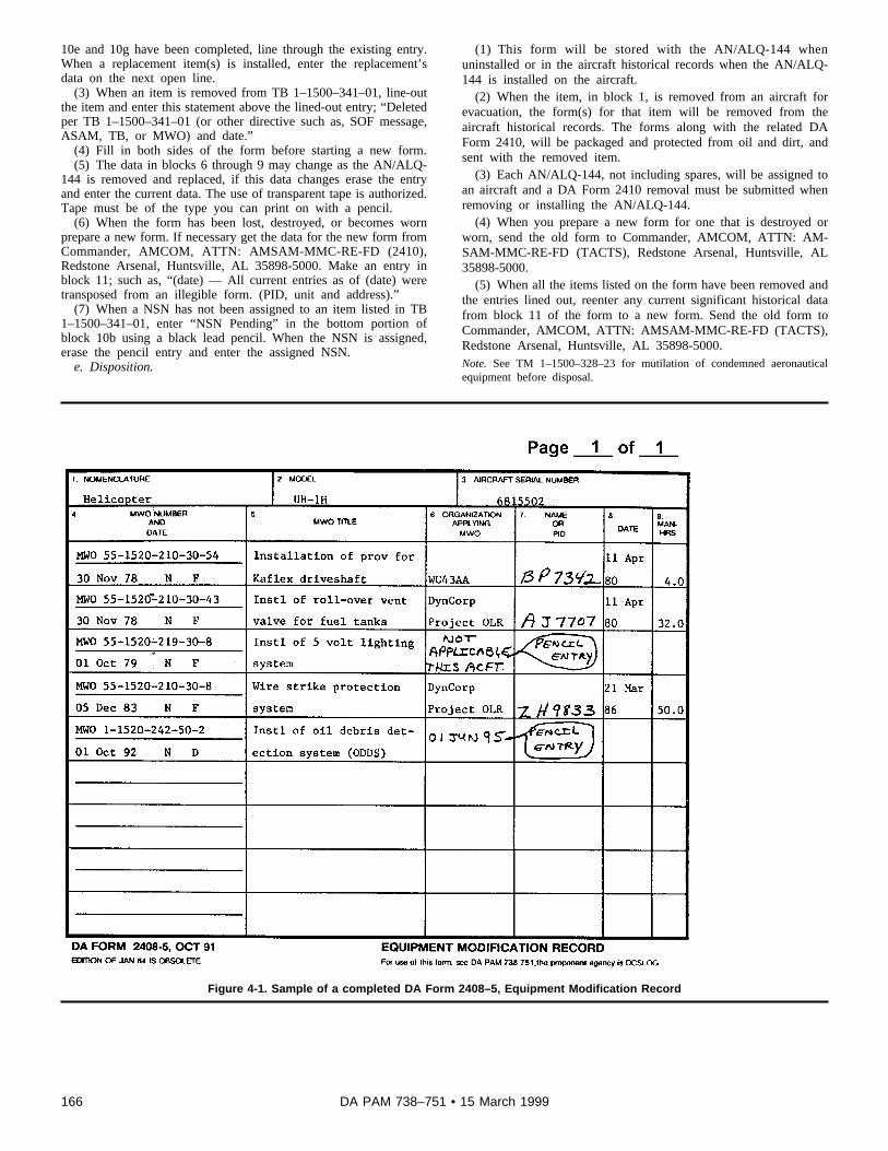
10e and 10g have been completed, line through the existing entry.When a replacement item(s) is installed, enter the replacement’sdata on the next open line.
(3) When an item is removed from TB 1–1500–341–01, line-outthe item and enter this statement above the lined-out entry; “Deletedper TB 1–1500–341–01 (or other directive such as, SOF message,ASAM, TB, or MWO) and date.”
(4) Fill in both sides of the form before starting a new form.(5) The data in blocks 6 through 9 may change as the AN/ALQ-
144 is removed and replaced, if this data changes erase the entryand enter the current data. The use of transparent tape is authorized.Tape must be of the type you can print on with a pencil.
(6) When the form has been lost, destroyed, or becomes wornprepare a new form. If necessary get the data for the new form fromC o m m a n d e r , A M C O M , A T T N : A M S A M - M M C - R E - F D ( 2 4 1 0 ) ,Redstone Arsenal, Huntsville, AL 35898-5000. Make an entry inblock 11; such as, “(date) — All current entries as of (date) weretransposed from an illegible form. (PID, unit and address).”
(7) When a NSN has not been assigned to an item listed in TB1–1500–341–01, enter “NSN Pending” in the bottom portion ofblock 10b using a black lead pencil. When the NSN is assigned,erase the pencil entry and enter the assigned NSN.
e. Disposition.
( 1 ) T h i s f o r m w i l l b e s t o r e d w i t h t h e A N / A L Q - 1 4 4 w h e nuninstalled or in the aircraft historical records when the AN/ALQ-144 is installed on the aircraft.
(2) When the item, in block 1, is removed from an aircraft forevacuation, the form(s) for that item will be removed from theaircraft historical records. The forms along with the related DAForm 2410, will be packaged and protected from oil and dirt, andsent with the removed item.
(3) Each AN/ALQ-144, not including spares, will be assigned toan aircraft and a DA Form 2410 removal must be submitted whenremoving or installing the AN/ALQ-144.
(4) When you prepare a new form for one that is destroyed orworn, send the old form to Commander, AMCOM, ATTN: AM-SAM-MMC-RE-FD (TACTS), Redstone Arsenal, Huntsville, AL35898-5000.
(5) When all the items listed on the form have been removed andthe entries lined out, reenter any current significant historical datafrom block 11 of the form to a new form. Send the old form toCommander, AMCOM, ATTN: AMSAM-MMC-RE-FD (TACTS),Redstone Arsenal, Huntsville, AL 35898-5000.Note. See TM 1–1500–328–23 for mutilation of condemned aeronauticalequipment before disposal.
Figure 4-1. Sample of a completed DA Form 2408–5, Equipment Modification Record
166 DA PAM 738–751 • 15 March 1999

Legend for Figure 4-1:Preparation Instructions (by block number and title) forcompleting a DA Form 2408–5, Equipment ModificationRecord
Page of . Enter the page number and total num-ber (black lead pencil) of pages.
1. NOMENCLATURE. Enter the item name.
2. MODEL. Enter the mission, design, and series of theaircraft.
3. AIRCRAFT SERIAL NUMBER. Enter the aircraft se-rial number (seven numeric digits).
4. MWO NUMBER AND DATE.
a. Enter the MWO number in the upper part of thisblock. The activity applying the MWO will normally com-plete this block. MWO’s not applied will be entered bythe unit/activity that determines that MWO was not ap-plied.
b. Enter the MWO publication date (dd mmm yy), priorityfor the MWO ("E" for Emergency, "U" for Urgent, or "R"for Routine) and the maintenance level responsible for
application of the MWO ("O" for AVUM, "F" for AVIM or"D" for Depot) in the bottom part of this block.
5. MWO TITLE. Enter the MWO abbreviated title.
6. ORGANIZATION APPLYING MWO. Enter the UIC,or the name of the organization that applied the MWO ordetermined that the MWO was previously applied. If aMWO is issued but not applied, enter the date that theMWO must be applied (black lead pencil). Erase thedate when the MWO is applied.
NOTE. Enter the MWO as overdue on DA Form2408–13–1 if the MWO has not been applied by the duedate.
7. NAME OR PID. The person who does the technicalinspection, to certify the MWO application, will enter hisor her PID in this block.
8. DATE. Enter the date (dd mmm yy) that the MWOwas applied.
9. MANHOURS. Enter the actual manhours it took toapply the MWO, to the nearest tenth of an hour, includ-ing the technical inspection.
167DA PAM 738–751 • 15 March 1999

Figure 4-2. Sample of a completed DA Form 2408–5–1, Equipment Modification Record (Component)
Legend for Figure 4-2:Preparation Instructions (by block number and title) forcompleting a DA Form 2408–5–1, Equipment Modifica-tion Record (Component)
Page of . Enter the page number and the totalnumber (black lead pencil) of pages.
1. NOMENCLATURE. Enter the component/modulename.
2. COMPONENT SERIAL NUMBER. Enter the compo-nent/module serial number.
3. AIRCRAFT SERIAL NUMBER. Enter the serial num-ber of the aircraft the component/module is installed on.Use a black lead pencil.
4. MWO NUMBER AND DATE. The owning unit orhigher level maintenance activity is responsible forentering all MWOs, SOF messages, ASAMs, and TBsthat apply to the component/module, regardless of themaintenance level responsible for application of theMWO, SOF message, ASAM, or TB compliance.
a. Enter the MWO, SOF, ASAM, or TB number in theupper half of the block.
b. In the lower half of the block, enter the date (dd mmmyy) of the MWO, SOF, ASAM, or TB; the priority forASAM or SOF messages ("E" for Emergency, "T" forTechnical, "M" for Maintenance Mandatory, or "O" forOperational), or for a MWO or TB ("E" for Emergency,"U" for Urgent, or "R" for Routine) and enter the mainte-nance level responsible for complying with the directive("O" for AVUM, "F" for AVIM, and "D" for Depot).
5. MWO TITLE. Enter the MWO, SOF, ASAM, or TBabbreviated title.
6. ORGANIZATION APPLYING MWO. Enter the UIC orthe name of the organization applying the directive.
7. NAME OR PID. The person who does the technicalinspection, or who will verify the MWO, SOF, ASAM, orTB application, will enter his or her PID.
8. DATE. Enter the date (dd mmm yy) the directive wasapplied.
9. MANHOURS. Enter the actual number of manhoursused to comply with the directive, including the technicalinspection.
168 DA PAM 738–751 • 15 March 1999

Figure 4-3. Sample of a completed DA Form 2408–15, Historical Record For Aircraft
Legend for Figure 4-3:Preparation Instructions (by block number and title) forcompleting a DA Form 2408–15, Historical Record ForAircraft
NOTE. When using the DA Form 2408–15 as a continu-ation page for DA Form 2408–16, block 7, or DA Form2408–16–1, block 14, enter "DA Form 2408–16 Continu-ation" or "DA Form 2408–16–1 Continuation" in the topmargin of the form.
Page of . Enter the page number and the totalnumber (black lead pencil) of pages.
1. AIRCRAFT MODEL. Enter the aircraft mission, de-sign, and series. When used as a DA Form 2408–16 or2408–16–1 continuation page, enter the part number ofthe component/module from DA Form 2408–16, block 3,or DA Form 2408–16–1, block 4.
2. NOMENCLATURE. Enter the item name. When usedas a DA Form 2408–16 or 2408–16–1 continuationpage, enter the name of the component/module from DAForm 2408–16, block 1 or DA Form 2408–16–1, block 3.
3. AIRCRAFT SERIAL NUMBER. Enter the aircraft se-rial number (seven numeric digits). When used as a DAForm 2408–16 or 2408–16–1 continuation page, enterthe serial number of the component/module from DAForm 2408–16, block 4 or DA Form 2408–16–1, block 2.
4. REMARKS.
a. Record any significant historical data about the air-frame.
b. The historical data entries should include completedata on SOF messages, ASAMs, TBs, One-time Inspec-tions for airframe items, scheduled inspections; such as,Phase or periodic, major repairs, conversions, over-hauls, and total aircraft hours at completion.
c. If the aircraft was involved in an accident, providecomplete details, including date (dd mmm yy), total air-craft flying hours, organization, and the cause and re-sults, if known.
d. When aircraft are removed from U.S. Armyaccountability, provide a close out statement verifying all
169DA PAM 738–751 • 15 March 1999

items on DA Form 2408–16 and/or 2408–16–1 are in-stalled or lined out if they have been removed.
e. ULLS-A users must make an entry showing the dateand time the conversion process to ULLS-A was com-pleted.
5. ORGANIZATION LOCATION. Enter the name of theunit/organization, and location of the unit that inspected,repaired, or overhauled the aircraft.
6. DATE. Enter the date (dd mmm yy) the action wascompleted.
7. ENTRY NUMBER. Manual Record keeping system;leave this block blank. ULLS-A users; entry is automati-cally entered.
8. PID. The person who verifies the maintenance actionwas completed or makes an entry will enter his or herPersonal Identifier in this block.
NOTE. Compliance of SOF messages, ASAMs, TBs,and one-time inspections on reportable components/modules will be recorded on individual component/mod-ule DA Form 2408–5–1.
Figure 4-4. Sample of a completed DA Form 2408–15–2, Aircraft Vibration Record
Legend for Figure 4-4:Preparation Instructions (by block number and title) forcompleting a DA Form 2408–15–2, Aircraft VibrationRecord
Page of . Enter the page number and the totalnumber (black lead pencil) of pages.
1. AIRCRAFT MODEL. Enter the aircraft mission, de-sign, and series.
2. NOMENCLATURE. Enter the item name.
3. AIRCRAFT SERIAL NUMBER. Enter the aircraft se-rial number (seven numerical digits).
4. IPS READINGS
170 DA PAM 738–751 • 15 March 1999

a. DATE. Enter the date (dd mmm yy) when thevibration test(s) were done.
b. AC HRS. Enter the aircraft operating hours, in hoursand tenths. Aircraft operating hours can be found on thecurrent DA Form 2408–13, block 11, FLIGHT DATA.
c. SHAFT. Enter the name of each component driveshaft that the vibration tests are done on.
d. LATERAL. Enter the IPS reading taken for the lateralaxis.
e. LONGITUDINAL. Enter the IPS reading taken for thelongitudinal axis.
f. VERTICAL. Enter the IPS reading taken for the verti-cal axis.
g. REASON FOR VIBRATION CHECK. Enter thereason(s) for the vibration test/check; for example,Scheduled 25 hour vibration test, 100 hour requirement,maintenance work, or component replacement.
5. REMARKS. Enter the date (dd mmm yy), other signif-icant historical data and/or actions taken to reduce vi-bration, PID, organization, and location.
Figure 4-5A. Sample of a completed DA Form 2408–16, Aircraft Component Historical Record (To record historical data on selectedaircraft components, modules) (Time Change Components) (Illustration #1)
171DA PAM 738–751 • 15 March 1999

Figure 4-5B. Sample of a completed DA Form 2408–16, Aircraft Component Historical Record (To record historical data on selectedaircraft components, modules) (Time Change Components) (Illustration #2)
172 DA PAM 738–751 • 15 March 1999

Figure 4-5C. Sample of a completed DA Form 2408–16, Aircraft Component Historical Record (To record historical data on selectedaircraft components, modules) (Condition Items) (Illustration #3)
173DA PAM 738–751 • 15 March 1999

Figure 4-5D. Sample of a completed DA Form 2408–16, Aircraft Component Historical Record (To record historical data on selectedaircraft components, modules) (Major Component Form) (Illustration #4)
174 DA PAM 738–751 • 15 March 1999

Figure 4-5E. Sample of a completed DA Form 2408–16, Aircraft Component Historical Record (To record historical data on selectedaircraft components, modules) (Major Component Form) (Illustration #5)
Legend for Figure 4-5E:Preparation Instructions (by block number and title) forcompleting a DA Form 2408–16 to record historical dataon selected aircraft components
NOTE. T-700 series gas turbine engine, major compo-nents, and subcomponents will not be recorded on theDA Form 2408–16. They are listed on DA Form2408–16–1, since they are removed and replaced atoperating hours on the engine, major component, orsubcomponents. This form is used only for selectedreportable components that are removed and replacedat specific aircraft flying hours.
Page of . Enter the page number and the totalnumber (black lead pencil) of pages.
1. NOMENCLATURE. Enter the item (aircraft or compo-nent) name.
2. NSN. Enter the aircraft or component National StockNumber. If the NSN changes because of MWO applica-tion, line out the old number and enter the new number.
3. PART NUMBER OR MODEL. When the item, inblock 1, is an aircraft or training device/simulator enterthe proper Mission Design Series. When the item is a
component enter the proper part number. If for anyreason the MDS or part number changes, line out theold number and enter the new one.
4. SERIAL NUMBER. Enter the aircraft or componentserial number.
5. WUC. Enter the work unit code for the major compo-nent listed in block 1. When block 1 contains an aircraft,leave blank. WUC’s can be found in TB1–1500–341–01.
6a. NOMENCLATURE AND WUC.
a. Enter on the top line the major component or sub-component name, listed in TB 1–1500–341–01, for youraircraft or major component in block 1. Make sure thatyou include each of the items listed in TB1–1500–341–01.
b. Enter the proper Work Unit Code on the bottom line.The WUC can be found in TB 1–1500–341–01, for eachcomponent/module.
6b. P/N AND NSN.
175DA PAM 738–751 • 15 March 1999

a. Enter on the top line the part number for the itemlisted in block 6a.
b. Enter on the bottom line the national stock number forthe item.
6c. COMPONENT SER NO. LOCATION. Enter the se-rial number and/or the location for the item listed inblock 6a. Enter the location of the item if no serial num-ber is assigned. The location may be entered along withthe serial number. Enter the software version for LRUs/black boxes that have software installed in the lowerhalf. Enter the pitch housing weight for the AH-64 mainrotor head assembly in the lower half.
6d. NO PREV O/H. If the item, in block 6a, is a TC itementer the number of overhauls the component/modulehas had from the DA Form 2410, Copy 3. If the TC itemhas never been overhauled enter "0." If the item is anRC or CC item, enter "RC" or "CC" whichever applieseven though the DA Form 2410 may show an overhaul.These codes can be found in TB 1–1500–341–01.
6e. NOMEN INST HRS. Enter the usage time sincenew, round to the nearest hour, for the item in block 1,when the item in block 6a is installed.
a. If the item in block 1 is an aircraft, get this figure fromthe current DA Form 2408–13, block 11, FLIGHT DATA,AIRCRAFT HOURS, CURRENT.
b. If the item, in block 1, is an uninstalled component/module, get this figure from the DA Form 2410.
c. If the item, in block 1, is an installed component/module, go to the aircraft DA Form 2408–16 and locatethe line for this component/module. Subtract the entryon the aircraft DA Form 2408–16, block 6e, from theaircraft hours shown on the current DA Form 2408–13,block 11. Add the results to the entry on the aircraft DAForm 2408–16, block 6h. Enter the sum, in this block,on the major subcomponent DA Form 2408–16.
6f. NOMEN RMVL HRS. Enter the usage time sincenew, rounded to the nearest hour, for the item listed inblock 1, when the item in block 6a is removed.
a. If the item, in block 1, is an aircraft, get this figurefrom the current DA Form 2408–13, block 11.
b. If the item, in block 1, is an uninstalled component/module, get this figure from the DA Form 2410.
c. If the item, in block 1, is an installed component/module, go to the aircraft DA Form 2408–16 and locatethe line for this component/module. Subtract the entryon the aircraft DA Form 2408–16, block 6e, from theaircraft hours shown on the current DA Form 2408–13.Add the result to the entry on the aircraft DA Form2408–16, block 6h. Enter the sum in this block on themajor subcomponent DA Form 2408–16 for the subcom-ponent being removed.
6g. TIME SINCE O/H. If the item is a TC item enter thenumber of operating hours, since the item, in block 6a,was last overhauled. Take this figure from the DA Form2410, Copy 3. If the TC item is new enter "0." If the item
is an RC or CC item, enter "RC" or "CC," whicheverapplies.
6h. COMP INST HRS. Enter "0," or the usage timesince new, rounded to the nearest hour, for the item inblock 6a. Get this figure from the DA Form 2410, Copy3.
6i. COMP RMVL HRS. When a component/module isremoved, enter the total accumulated operating hours.This is obtained by subtracting block 6e from 6f, andadding 6h.
6j. O/H OR REPLAC LIFE. For CC components/mod-ules enter "COND." For TC and RC components/mod-ules enter the maximum allowable operating time(MAOT) from the applicable -23 TM. When the TBO or"time to replacement" is changed, line out the old timeand enter the new time. If the authority for this changewas other than a change to the -23 TM, enter the au-thority in block 7.
6k. REPLACEMENT DUE (ACFT HRS). Enter the air-craft operating hours that the component/module or partmust be replaced by. Complete this column as follows:
a. On a component/module form only, the entry will bein black lead pencil.
b. For Condition Change DA Form 2408–16 and otherCondition Change subcomponents entered on DA Form2408–16 enter "COND."
c. For the Aircraft Time Change DA Form 2408–16 thefollowing applies:
(1) If the item, in block 6a, is a RC item or a TC itemthat has never been overhauled (block 6d is RC or 0),subtract block 6h from 6j, and add to 6e.
(2) If the item, in block 6a, is a TC item that has beenpreviously overhauled (block 6d has 1, 2, 3, or so on),subtract block 6g from 6j, and add to 6e.
d. For the major component/module DA Form 2408–16the following applies:
(1) Depot level maintenance activities will leave thisblock blank. This block will be filled in when the majorcomponent/module is installed on the next higher as-sembly and listed on the next higher assembly TimeChange or Condition Change DA Form 2408–16.
(2) If the subcomponent listed in block 6a is a RC itemor a TC item that has never been overhauled (block 6dis RC or 0), subtract block 6h from 6j and add to block6e; then go to the aircraft DA Form 2408–16 and locatethe major component and add block 6e from the aircraftform to the total you got from the component form andsubtract block 6h of the aircraft form and enter this totalin block 6k on the component form. The formula lookslike this:
(component form) 6j - 6h + 6e + (aircraft form) 6e - 6h =6k on the component form.
(3) If the subcomponent listed in block 6a is a TC itemthat reflects an overhaul number (1, 2, or 3) in block 6d,subtract block 6g from 6j and add to block 6e; then go to
176 DA PAM 738–751 • 15 March 1999
the aircraft DA Form 2408–16 and locate the majorcomponent and add block 6e from the aircraft form tothe total from the component form and subtract block 6hof the aircraft form and enter this total in block 6k on thecomponent form. The formula looks like this:
(component form) 6j - 6g + 6e + (aircraft form) 6e - 6h =6k on the component form.
e. When an item reaches the MAOT time or the "re-placement due time" and an extension is granted, or thetime is officially changed by the NMP, line out the origi-nal entry in this column and enter the new time.
NOTE. Some components may be listed as TBO andRC in the TM -23 maintenance manual. When this situa-tion occurs, only make one entry for the component onthe DA Form 2408–16. Draw a horizontal line throughthe center of blocks 6j and 6k. Enter the TBO interval inthe top portion and the RC interval in the bottom portionof block 6j. Enter the TBO replacement due time in the
top portion and the RC replacement due time in thebottom portion of block 6k. ULLS-A and LAS users willhave two entries for this situation, one entry for the TBOand another entry for RC time.
7. SIGNIFICANT HISTORICAL DATA. Enter any signifi-cant historical data on aircraft components/modules andparts. Before you enter the data, enter the date (ddmmm yy) of your entry. After you enter the historicaldata, enter your PID, organization, and location. If morespace is needed, use a DA Form 2408–15 as a continu-ation sheet. Print "DA Form 2408–16 Continuation" inthe top margin of the form and complete the form head-ing with the aircraft or component information. The fol-lowing are examples of significant historical data: Crashdamage, contamination, saltwater immersion, and HSFcounts on T703 engines. For components that are re-moved at specific operating hours for rework or othermaintenance actions, such as, "rotor head componentsremoved at 1200 hrs. for rework (turned 180 degrees)and reinstalled" will be entered in this block.
177DA PAM 738–751 • 15 March 1999

Figure 4-6A. Sample of a completed DA Form 2408–16–1, History Recorder Component Module Record. T700 series engine showing majo rmodules and components. (Illustration #1)
178 DA PAM 738–751 • 15 March 1999

Figure 4-6B. Sample of a completed DA Form 2408–16–1, History Recorder Component Module Record. T700 series engine showing majo rmodules and components. (Illustration #2)
179DA PAM 738–751 • 15 March 1999

Figure 4-6C. Sample of a completed DA Form 2408–16–1, History Recorder Component Module Record. T700 series engine showing majo rmodules and components. (Illustration #3)
Legend for Figure 4-6C:Preparation Instructions (by block number and title) forcompleting a DA Form 2408–16–1 for an engine show-ing major modules/components
Page of . Enter page number and total number(black lead pencil) of pages.
1. MODEL. Enter the engine model.
2. ENG S/N. Enter the engine serial number.
3. NOMENCLATURE. Enter "Engine."
4. P/N. Enter the manufacturer’s part number.
5. S/N. Enter the aircraft serial number that the engine isinstalled on (black lead pencil). If the engine is uninstal-led, leave blank.
6. HISTORICAL COUNTS ON COMPONENT/MOD-ULE.
LINE 1+ — PREVIOUS COUNTS OF COMPONENT/MODULE (New engine will have counts from test celltime or from last completed block 6, line 5=.)
a. LCF-1. Enter the total cumulative LCF-1 counts forthe engine.
b. LCF-2. Enter the total cumulative LCF-2 counts forthe engine.
c. TIME/TEMP INDEX. Enter the total cumulative Time/Temp Index (T/TI) counts for the engine.
d. OPERATING HOURS. Enter the total cumulative op-erating hours for the engine.
LINE 2- — READING AT INSTALLATION OF MODULE/RECORDER. Enter LCF-1, LCF-2, T/TI, and Operating
180 DA PAM 738–751 • 15 March 1999

Hours readings on the history recorder when Line 1+ iscompleted.
Lines 3, 4= and 5=. These lines will be completed if thehistory recorder is replaced.
7. HISTORY RECORDER S/N. Enter the history re-corder serial number.
NOTE. When two or more pages are needed to enterthe modules/components on the reverse side of theform, no entries are required in block 6 of the additionalpages unless the front side of page 1 is filled.
BACKSIDE.
8. NOMENCLATURE. Enter the name of each replacea-ble module/component listed in TB 1–1500–341–01.
9. PART NUMBER. Enter the manufacturer’s part num-ber of each module/component.
10. SERIAL NUMBER. Enter the serial number of eachmodule/component.
11. O/H OR REPLACEMENT LIFE.
a. If the item, in block 8, has an established MAOT foroverhaul, rebuild, or retirement enter the MAOT in thisblock.
b. If the item, in block 8, is a CC item enter "COND" inthis block.
c. When the TBO or time to replacement is changed,line out the old time and enter the new time. If theauthority for this change was other than a change to the-23 TM, enter the authority in block 14.
12. HISTORICAL COUNTS AT LAST DEPOT RE-PLACEMENT. The purpose of these blocks is to recordwhat the total cumulative counts and hours were on themodules/components when they were installed on theengine and the total cumulative counts and hours on theengine at the time of module/component installation.The blocks will be split in half to accommodate twoentries in each block. One entry in the top half of theblock and one entry in the bottom half of the block. Todetermine the total cumulative counts and hours on theengine, read the engine history recorder to obtain thecurrent reading. Make sure that the history recorder se-rial number matches the history recorder serial numberentered in block 7 of the engine DA Form 2408–16–1.Subtract the entry in block 6, line 2- of the engine DAForm 2408–16–1 from the history recorder reading. Addthese counts and hours to the entry in block 6, line 1+ ofthe engine DA Form 2408–16–1. This is the total cumu-lative counts and hours on the engine. Obtain the totalcumulative counts and hours of the module/componentbeing installed from block 13 of the DA Form 2410shipped with the module/component.
12a. Enter the total cumulative LCF-1 counts for theengine, at the time of module/component installation, inthe top half of the block. Enter the total cumulative LCF-1 counts for the module/component being installed inthe bottom half of the block
12b. Enter the total cumulative LCF-2 counts for theengine, at the time of module/component installation, inthe top half of the block. Enter the total cumulative LCF-2 counts for the module/component being installed inthe bottom half of the block.
12c. Enter the total cumulative T/TI counts for the en-gine, at the time of module/component installation, in thetop half of the block. Enter the total cumulative T/TIcounts for the module/component being installed in thebottom half of the block.
12d. Enter the total cumulative operating hours for theengine, at the time of module/component installation, inthe top half of the block. Enter the total cumulative oper-ating hours for the module/component being installed inthe bottom half of the block. If the item is a TC item andhas been previously overhauled enter the time sinceoverhaul. If the item is a TC item and never overhauled,enter the time since new.
NOTE. When this form is prepared for the engine,blocks 12a (LCF-1), 12b (LCF-2), and 12c (T/TI) willonly be completed for the history recorder, cold sectionmodule, power turbine module and matched rotor/stator(GG turbine rotor assy). Blocks 12a, 12b and 12c will beleft blank for all other modules/components entered onthe engine DA Form 2408–16–1.
13. REPLACEMENT DUE (Hist rcdr hr). If the module/component is a TC or RC item the replacement timemust be calculated. The replacement due time will beexpressed in history recorder hours.
a. Calculate the replacement due for a RC item as fol-lows:
(1) Read the engine history recorder at the time of mod-ule/component installation.
(2) Subtract the total cumulative hours in the top half ofblock 12d from the entry in the most current block 6d,line 1. Add to the total cumulative hours in the bottomhalf of block 12d and subtract from the MAOT in block11. Add this amount to the entry in block 6d, line 2.Enter this figure in block 13.
b. Calculate the replacement due for a TC item as fol-lows:
(1) Read the engine history recorder at the time of mod-ule/component installation.
(2) If the TC item has never been overhauled, subtractthe total cumulative module/component hours in the bot-tom half of block 12d from the assigned retirement lifeentered in block 11. Add the results to the current his-tory recorder hours. This figure will be the history re-corder hours that the module/component is duereplacement.
(3) If the TC item has been previously overhauled, sub-tract the hours since overhaul from the assigned retire-ment life entered in block 11. Add the results to thecurrent history recorder hours. This figure will be thehistory recorder hours that the module/component isdue replacement.
181DA PAM 738–751 • 15 March 1999
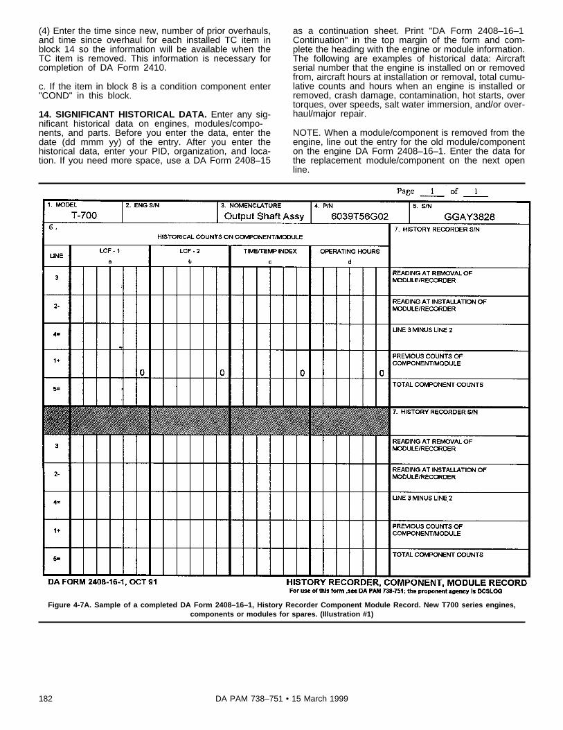
(4) Enter the time since new, number of prior overhauls,and time since overhaul for each installed TC item inblock 14 so the information will be available when theTC item is removed. This information is necessary forcompletion of DA Form 2410.
c. If the item in block 8 is a condition component enter"COND" in this block.
14. SIGNIFICANT HISTORICAL DATA. Enter any sig-nificant historical data on engines, modules/compo-nents, and parts. Before you enter the data, enter thedate (dd mmm yy) of the entry. After you enter thehistorical data, enter your PID, organization, and loca-tion. If you need more space, use a DA Form 2408–15
as a continuation sheet. Print "DA Form 2408–16–1Continuation" in the top margin of the form and com-plete the heading with the engine or module information.The following are examples of historical data: Aircraftserial number that the engine is installed on or removedfrom, aircraft hours at installation or removal, total cumu-lative counts and hours when an engine is installed orremoved, crash damage, contamination, hot starts, overtorques, over speeds, salt water immersion, and/or over-haul/major repair.
NOTE. When a module/component is removed from theengine, line out the entry for the old module/componenton the engine DA Form 2408–16–1. Enter the data forthe replacement module/component on the next openline.
Figure 4-7A. Sample of a completed DA Form 2408–16–1, History Recorder Component Module Record. New T700 series engines,components or modules for spares. (Illustration #1)
182 DA PAM 738–751 • 15 March 1999

Figure 4-7B. Sample of a completed DA Form 2408–16–1, History Recorder Component Module Record. New T700 series engines,components or modules for spares. (Illustration #2)
Legend for Figure 4-7B:Preparation Instructions (by block number and title) forcompleting a DA Form 2408–16–1 on a new module/component for spares
Page of . Enter page number and total number(black lead pencil) of pages.
1. MODEL. Enter the module/component model.
2. ENG S/N. Enter engine serial number (black leadpencil) when installed. For items not installed on anengine, leave blank.
3. NOMENCLATURE. Enter the name of the module/component.
4. P/N. Enter the manufacturer’s part number.
5. S/N. Enter the module/component serial number.
6. HISTORICAL COUNTS ON COMPONENT/MOD-ULE.
LINE 1+ — PREVIOUS COUNTS OF COMPONENT/MODULE. Enter the total cumulative LCF-1, LCF-2, T/TI, and Operating Hours for the module/component aftercompletion of test run.
LINE 2- — READING AT INSTALLATION OF MOD-ULE/RECORDER. Leave blank.History recorder read-ings will be entered when item is installed on an engine.
LINES 3, 4=, and 5=. These lines will be completedwhen the history recorder is replaced.
7. HISTORY RECORDER S/N. Leave blank. The history
183DA PAM 738–751 • 15 March 1999

recorder serial number will be entered when the module/component is installed on an engine.
NOTE. When two or more pages are needed to enterthe subcomponents on the reverse side of the forms, noentries are required in block 6 of additional pages un-less the front side of page 1 is filled.
BACKSIDE.
8. NOMENCLATURE. Enter the name of each replacea-ble subcomponent.
9. PART NUMBER. Enter the manufacturer’s part num-ber of each subcomponent.
10. SERIAL NUMBER. Enter the serial number of eachsubcomponent.
11. O/H OR REPLACEMENT LIFE.
a. If the item in block 8 has an established MAOT foroverhaul, rebuild, or retirement enter the MAOT in thisblock.
b. If the item in block 8 is a condition change componententer "COND" in this block.
12. HISTORY COUNTS AT LAST DEPOT REPLACE-MENT.
a. The purpose of these blocks is to record the totalcumulative counts and hours on the subcomponentswhen they were installed on the module/component and
the total cumulative counts and hours on the module/component at the time of subcomponent installation.
b. The block will be split in half to accommodate twoentries. One entry in the top half of the block and oneentry in the bottom half of the block. The total cumula-tive counts for the module/component in block 3, at thetime of subcomponent installation, will be entered in thetop portion of this block. The total cumulative counts foreach subcomponent, at the time of installation, will beentered in the bottom portion of the block.
13. REPLACEMENT DUE (Hist rcdr hr).
a. If the subcomponent has an established MAOT, leaveblank. The replacement due will be calculated when themodule or component is installed on an engine.
b. If the subcomponent is a condition change compo-nent enter "COND" in this block.
14. SIGNIFICANT HISTORICAL DATA. Enter any sig-nificant historical data on modules/components, andparts. Enter the date (dd mmm yy) before you enter thedata. After you enter the historical data, enter yourname, organization, and location. If you need morespace, use a DA Form 2408–15 as a continuation sheet.Print "DA Form 2408–16–1 Continuation" in the top mar-gin of the form and complete the heading with the mod-ule/component information. The following are examplesof significant historical data: Crash damage, contamina-tion, hot starts, over torques, over speeds, salt waterimmersion, and overhaul or major repair.
184 DA PAM 738–751 • 15 March 1999

Figure 4-8A. Sample of a completed DA Form 2408–16–1, History Recorder Component Module Record. Removal of a module from a T700series engine. (Illustration #1)
185DA PAM 738–751 • 15 March 1999

Figure 4-8B. Sample of a completed DA Form 2408–16–1, History Recorder Component Module Record. Installation of a module on a T 700series engine. (Illustration #2)
186 DA PAM 738–751 • 15 March 1999

Figure 4-8C. Sample of a completed DA Form 2408–16–1, History Recorder Component Module Record. Installation of a module on a T 700series engine. (Illustration #3)
Legend for Figure 4-8C:Preparation Instructions (by block number and title) forcompleting a DA Form 2408–16–1, removal or installa-tion of a module/component having a separate DA Form2408–16–1.
Page of . Enter page number and total number(black lead pencil) of pages.
NOTE. Follow these procedures when installing a mod-ule/component with a separate DA Form 2408–16–1.Enter the module/component listed in block 3 of theseparate DA Form 2408–16–1 on the correct nexthigher assembly DA Form 2408–16–1. Make the follow-ing entries on the separate module or component DAForm 2408–16–1.
Blocks 1, 3, 4, 5, and 6 (Line 1+). Already completedon the form when a module/component is received.
2. ENG S/N. When the next higher assembly of the
module/component is the engine, enter the engine serialnumber (black lead pencil).
6. HISTORICAL COUNTS ON COMPONENT/MOD-ULE.
a. LINE 2- — READING AT INSTALLATION OF MOD-ULE/RECORDER. Enter the current LCF-1, LCF-2, T/TI,and Operating Hours on the history recorder when in-stalling a module/component on an engine.
NOTE. Do not complete Lines 3, 4=, and 5= for installa-tion.
b. LINE 3 — READING AT REMOVAL OF MODULE/RECORDER. Enter the current LCF-1, LCF-2, T/TI, andOperating Hours on the history recorder when removinga module/component from an engine.
c. LINE 4= — LINE 3 MINUS LINE 2. Subtract thereadings on line 2- from readings on line 3 to get theoperating hours since last installation. Transfer the
187DA PAM 738–751 • 15 March 1999
hours to DA Form 2410, Copy 1, block 7, prepared forthe module/component.
d. LINE 5= — TOTAL COMPONENT COUNTS. Add line4= to line 1+ for total cumulative counts. Transfer thecounts to DA Form 2410, Copy 1, block 13, prepared forthe module/component. Transfer total cumulative oper-ating hours from block 6, line 5=, Operating Hours, tothe DA Form 2410, Copy 1, block 8.
7. HISTORY RECORDER S/N. Enter the history re-corder serial number when installing the module/compo-nent on an engine.
NOTE. When two or more pages are needed to enterthe modules/components on the reverse side of theforms, no entries are required in block 6 of the additionalpages unless the front side of page 1 is filled.
BACKSIDE
Blocks 8 through 12. These blocks should be filled inbefore module/component installation. LCF-1, LCF-2, T/TI and OP Hours are required for every subcomponententered on a module/component DA Form 2408–16–1.When the TBO or time to replacement is changed, lineout the old time and enter the new time. If the authorityfor this change was other than a change to the -23 TM,enter the authority in block 14.
13. REPLACEMENT DUE (Hist rcdr hr). If the module/component is a TC or RC item the replacement timemust be calculated. The replacement due time will beexpressed in history recorder hours.
a. Calculate the replacement due for a RC item as fol-lows:
(1) Read the engine history recorder at the time of mod-ule/component installation.
(2) Subtract the total cumulative hours in the top half ofblock 12d from the entry in the most current block 6d,line 1. Add to the bottom half of block 12d and subtractfrom the MAOT in block 11. Add this amount to the entryin block 6d, line 2. Enter this figure in block 13.
b. Calculate the replacement due for a TC item as fol-lows:
(1) Read the engine history recorder at the time of mod-ule/component installation.
(2) If the TC item has never been overhauled, subtractthe total cumulative subcomponent hours in the bottomhalf of block 12d from the assigned retirement lifeentered in block 11. Add this amount to the currenthistory recorder hours. This figure will be the historyrecorder hours that the subcomponent is due replace-ment.
(3) If the TC has been previously overhauled, subtractthe hours since overhaul from the assigned retirementlife entered in block 11. Add this amount to the currenthistory recorder hours. This figure will be the historyrecorder hours that the subcomponent is due replace-ment.
(4) Enter the prior overhauls and time since overhaul foreach installed TC item in block 14 so the information willbe available when the TC item is removed. This infor-mation is necessary for completion of the DA Form2410.
14. SIGNIFICANT HISTORICAL DATA. Enter any sig-nificant historical data on moduels/components, andparts. Enter the date (dd mmm yy) before you enter thedata. After you enter the historical data, enter yourname, organization, and location. If you need morespace, use a DA Form 2408–15 as a continuation sheet.Print "DA Form 2408–16–1 Continuation" in the top mar-gin of the form and complete the heading with the en-gine or module information. The following are examplesof significant historical data: Crash damage, contamina-tion, hot starts, over torques, over speeds, salt waterimmersion, and overhaul or major repair.
NOTE. For removed module/component attach the DAForm 2408–16–1 along with the DA Form 2410 to theitem for shipment to higher level maintenance activity.Entries are also required on the engine DA Form2408–16–1 when moduels/components are removed orinstalled on the engine.
188 DA PAM 738–751 • 15 March 1999

Figure 4-9A. Sample of a completed DA Form 2408–16–1, History Recorder Component Module Record. Depot repair of a T700 seriesengine module. (Illustration #1, Front)
189DA PAM 738–751 • 15 March 1999

Figure 4-9B. Sample of a completed DA Form 2408–16–1, History Recorder Component Module Record. Depot repair of a T700 seriesengine module. (Illustration #2, Reverse)
Legend for Figure 4-9B:Preparation Instructions (by block number and title) forcompleting a DA Form 2408–16–1, Depot Repair
NOTE. When an unserviceable engine is received atdepot level, read the history recorder, enter this readingon block 6, line 3 and complete lines 4= and 5= of theengine DA Form 2408–16–1. Complete block 6 for eachmodule/component having a separate DA Form2408–16–1.
Blocks 1, 3, 4, and 5. Should be filled in. If not, enterthe required information.
2. ENG S/N. When the form is for a module/componentleave blank until the module/component is installed onan engine or module/component. When the form is foran engine enter the engine serial number
6. HISTORICAL COUNTS ON COMPONENT/MOD-ULE.
LINE 1+ — PREVIOUS COUNTS OF COMPONENT/MODULE.
a. Enter the total cumulative counts from the last com-pleted block 6, line 5= to the next open block 6.
b. If the module/component has been operated on aslave engine to ensure serviceability after repair, thetotal cumulative counts/hours must be updated.
(1) Calculate the LCF-1, LCF-2, Time/Temp Index, andOperating Hours accumulated by the engine or module/component while operating on the slave engine.
(2) Add these counts/hours to the total cumulativecounts entered on line 1+.
(3) Line out the existing figures in line 1+ and enter theupdated counts/hours above the old figure.
LINE 2- - READING AT INSTALLATION OF MODULE/RECORDER. When this form is prepared for a module/
190 DA PAM 738–751 • 15 March 1999

component leave blank until the component is installedon an engine.
7. HISTORY RECORDER S/N. When this form is pre-pared for a module/component leave blank until thecomponent is installed on an engine. For an engineenter the history recorder serial number.
NOTE. When two or more pages are needed to enterthe modules/components on the reverse side of theforms, no entries are required in block 6 of the additionpages unless the front side of page 1 is filled.
BACKSIDE.
NOTE. For completion of the backside of the engine DAForm 2408–16–1 refer to the instructions for figure 4–6.Complete the reverse side of a separate module/compo-nent DA Form 2408–16–1 as follows.
8. NOMENCLATURE. Enter the name of each installedsubcomponent of the module/component on the nextopen line.
9. PART NUMBER. Enter the manufacturer’s part num-ber of each installed subcomponent of the module/com-ponent on the next open line.
10. SERIAL NUMBER. Enter the serial number of eachinstalled subcomponent of the module/component onthe next open line.
11. O/H OR REPLACEMENT LIFE.
a. If the item in block 8 has an established MAOT, enterthe MAOT in this block.
b. If the item in block 8 is a condition change module/component enter "COND" in this block.
c. When the TBO or "time to replacement" is changed,line out the old time and enter the new time. If theauthority for this change was other than a change to the-23 TM, enter the authority in block 14.
12. HISTORY COUNTS AT LAST DEPOT REPLACE-MENT.
a. Removing a subcomponent from a module/compo-nent with a separate DA Form 2408–16–1. Calculate thetotal cumulative counts and hours for each subcom-ponent removed by subtracting the total cumulativecounts and hours entered in the top half of blocks 12athrough 12d from the counts and hours entered in block6, line 5= and adding this amount to the entries in thebottom portions of blocks 12a through 12d. These arethe total cumulative counts and hours since new for thesubcomponent. Enter these counts and hours on DAForm 2410, Copy 1, blocks 13a through 13d. In addition,enter the total cumulative operating hours since new onthe DA Form 2410, Copy 1, block 8. Line out the entryon the DA Form 2408–16–1.
b. Installing a subcomponent on a module/componentwith a separate DA Form 2408–16–1. The purpose ofthese blocks is to record what the total cumulativecounts and hours were on the subcomponents whenthey were installed on the module/component and the
total cumulative counts and hours on the module/com-ponent at the time of subcomponent installation. Theblocks will be split in half to accommodate two entries ineach block. One entry in the top half of the block andone entry in the bottom half of the block. Obtain the totalcumulative counts for the module/component from themodule/component DA Form 2408–16–1, block 6, line5=. Obtain the total cumulative counts and hours foreach subcomponent being installed from the subcom-ponent DA Form 2410, block 13.
12a. Enter the total cumulative LCF-1 counts for themodule/component, at the time of subcomponent instal-lation, in the top half of the block. Enter the total cumula-tive LCF-1 counts for the subcomponent being installedin the bottom half of the block.
12b. Enter the total cumulative LCF-2 counts for themodule/component, at the time of subcomponent instal-lation, in the top half of the block. Enter the total cumula-tive LCF-2 counts for the subcomponent being installedin the bottom half of the block.
12c. Enter the total cumulative T/TI counts for the mod-ule/component, at the time of subcomponent installation,in the top half of the block. Enter the total cumulative T/TI counts for the subcomponent being installed in thebottom half of the block.
12d. Enter the total cumulative operating hours for themodule/component, at the time of subcomponent instal-lation, in the top half of the block. Enter the total cumula-tive operating hours for the subcomponent beinginstalled in the bottom half of the block.
13. REPLACEMENT DUE (Hist rcdr hr).
a. If the form is completed for a module/component witha separate DA Form 2408–16–1 enter "COND" for eachCC item listed. For RC and TC items, leave block 13blank until the module/component is installed on an en-gine.
b. When the module/component is installed on an en-gine enter the engine history recorder readings on themodule/component DA Form 2408–16–1, block 6, line2-. If the subcomponent is a TC or RC item the replace-ment time must be calculated. The replacement duetime will be expressed in history recorder hours.
c. Calculate the replacement due for a RC item by sub-tracting the hours in the top half of block 12d from theentry in the most current block 6d, line 1. Add to thetotal cumulative hours in the bottom half of block 12dand subtract from the MAOT in block 11. Add thisamount to the entry in block 6d, line 2. Enter this figurein block 13.
d. Calculate the replacement due for a TC item as fol-lows:
(1) If the TC item has never been overhauled, subtractthe total subcomponent hours in the bottom half of block12d from the assigned retirement life entered in block11. Add this amount to the entry in block 6d, line 2- onthe front side of the form. This figure will be the historyrecorder hours that the module/component is due re-placement.
191DA PAM 738–751 • 15 March 1999

(2) If the TC item has been previously overhauled, sub-tract the hours since overhaul from the assignedretirement life entered in block 11. Add this amount tothe entry in block 6d, line 2- on the front side of theform. This figure will be the history recorder hours thatthe subcomponent is due replacement.
(3) Enter the prior overhauls and time since overhaul foreach installed TC item in block 14 so the information willbe available when the TC item is removed. This infor-mation is necessary for completion of DA Form 2410.
14. SIGNIFICANT HISTORICAL DATA. Enter any sig-nificant historical data on engines, modules/componentsand parts. Before you enter the data, enter the date ofyour entry. After you enter the historical data, enter youname, organization, and location. If you need morespace, use a DA Form 2408–15 as a continuation sheet.Print "DA Form 2408–16–1 Continuation" in the top mar-gin of the form and complete the heading with the en-gine or component information. The following areexamples of significant historical data: Engine installa-tion and removal from an aircraft, total cumulativecounts when an engine is removed or installed, crashdamage, contamination, hot starts, over torques, overspeeds, salt water immersion, and overhaul/major repairdata.
Figure 4-10A. Sample of a completed DA Form 2408–16–1, History Recorder Component Module Record. Replacement of a T700 seriesengine history recorder. (Illustration #1)
192 DA PAM 738–751 • 15 March 1999

Figure 4-10B. Sample of a completed DA Form 2408–16–1, History Recorder Component Module Record. Replacement of a T700 seriesengine history recorder. (Illustration #2)
Legend for Figure 4-10B:Preparation Instructions (by block number and title) forcompleting a DA Form 2408–16–1, replacement of ahistory recorder
NOTE. When an engine history recorder is replaced, allthe DA Forms 2408–16–1 (engine and major compo-nents) must have block 6 completed for the old historyrecorder and in the next open block 6, line 1+ (previouscounts of module/component, get from line 5= of theprevious block 6) and line 2- (history recorder readingsat time of installation) must be completed for the newhistory recorder. Add another DA Form 2408–16–1, ifboth block 6 are completely filled on the engine, module/component form. Be sure the serial number of the his-tory recorder you are removing matches the serial num-ber on the DA Form(s) 2408–16–1. Check lines 2-, 3,4=, and 5=, for discrepancies. If any discrepancies arefound, contact the 2410 Hot line: AVUM, AVIM, andAVCRADs call DSN 897–2410 or Commercial (256)
313–2410, Contractors call DSN 746–2851 or Commer-cial (256) 876–2851, and CCAD personnel call DSN861–4544 or Commercial (512) 939–4544. Do not con-tinue with the paperwork until all discrepancies are re-solved.
Blocks 1, 2, 3, 4, and 5. Make sure that the enginemodel, serial number, name, manufacturer’s part num-ber, and component serial number are correctly entered.
6. HISTORICAL COUNTS ON COMPONENT/MOD-ULE.
LINE 3 — READING AT REMOVAL OF MODULE/RE-CORDER. Enter the recorder reading at time of historyrecorder removal. If the recorder is inoperative, everyeffort should be made to establish the correct data. Ifthe engine data can not be reconstructed, contact theAMCOM DA Form 2410 Hot line.
193DA PAM 738–751 • 15 March 1999

LINE 4= — LINE 3 MINUS LINE 2. Subtract Line 2-from Line 3.
LINE 5= — TOTAL COMPONENT COUNTS. Add Line1+ to Line 4=. Enter total on Line 1+ in the next openblock 6. If the total cumulative counts were calculateddue to history recorder failure, make an entry in block 14and the REMARKS block of DA Form 2410, copies 1and 2, prepared for the failed history recorder statingthat the total cumulative counts were calculated due tohistory recorder failure.
NEW BLOCK 6.
LINE 1+ — PREVIOUS COUNTS OF COMPONENT/
MODULE. Reenter the total from the prior block 6, line5=.
LINE 2- — READING AT INSTALLATION OF MOD-ULE/RECORDER. Enter the new history recorder read-ings at the time of installation.
7. HISTORY RECORDER S/N. Enter the serial numberof the new history recorder you are installing.
NOTE. When a history recorder is replaced the entrieson the DA Forms 2408–16–1, block 13, must be recal-culated for RC and TC major components and subcom-ponents. Failure to recalculate the replacement due timemay result in exceeding the retirement life of theseitems.
Figure 4-11A. Sample of a completed DA Form 2408–16–1, History Recorder Component Module Record. Depot repair or overhaul of a H-60 series aircraft APU. (Illustration #1, Front)
194 DA PAM 738–751 • 15 March 1999

Figure 4-11B. Sample of a completed DA Form 2408–16–1, History Recorder Component Module Record. Depot repair or overhaul of a H-60 series aircraft APU. (Illustration #2, Reverse)
Legend for Figure 4-11B:Preparation Instructions (by block number and title) forcompleting a DA Form 2408–16–1, APU Depot Repair.
NOTE. Review the form that came with the APU. Block6, Lines 1 through 5, should already be filled in. If Lines4 and/or 5 are blank, do the calculations and fill them in.Total operating hours will only be entered for APUs withinstalled hour meters.
Page of . Enter page number and total number(black lead pencil) of pages.
1. MODEL. Enter APU model.
2. ENG S/N. Enter the APU serial number
3. NOMENCLATURE. Enter "APU."
4. P/N. Enter the manufacturer’s part number.
5. S/N. Leave blank.
6. HISTORICAL COUNTS ON COMPONENT/MOD-ULE.
LINE 1 — PREVIOUS COUNTS OF COMPONENT/MODULE
a. LCF-1. The number of prior overhauls on the APU.Zero for new item.
b. LCF-2. The number of starts since the last overhaul.Zero for new item.
c. TIME/TEMP INDEX. The total number of starts sincenew. Zero for new item.
NOTE. The number of starts since new will not be ze-roed after repair or overhaul.
d. OPERATING HOURS. The operating hours since
195DA PAM 738–751 • 15 March 1999

new. If the APU does not have an hour meter, leaveblank.
NOTE. The operating hours will not be zeroed afterrepair or overhaul.
LINE 2- — READING AT INSTALLATION OF MOD-ULE/RECORDER
a. LCF-1. The prior overhauls, same as Line 1.
b. LCF-2. The number of starts since the last overhaul,same as Line 1.
c. TIME/TEMP INDEX. The number of starts from theAPU hour meter.
d. OPERATING HOURS. The operating hours from theAPU hour meter. If the APU does not have an hourmeter, leave blank.
LINE 3 — READING AT REMOVAL OF MODULE/RE-CORDER
a. LCF-1. The prior overhauls, same as Line 1.
b. LCF-2. The starts since last overhaul.
(1) If the APU has an hour meter, with number of startson it, subtract line 2, block 6c from starts shown on theAPU hour meter. Add this to line 1, block 6b, and enterhere for total number of starts since last overhaul.
(2) If the APU does not have an hour meter, with num-ber of starts on it, subtract line 2, block 6c from thenumber of starts on the current DA Form 2408–13,block 7. Add this to line 1, block 6b, and enter here fortotal number of starts since last overhaul.
c. TIME/TEMP INDEX. The starts since new.
(1) If the APU has an hour meter with the number ofstarts, enter the meter reading.
(2) If the APU does not have an hour meter with thetotal number of starts, enter the number of starts fromthe current DA Form 2408–13, block 7.
d. OPERATING HOURS. The number of operatinghours from the APU hour meter. If the APU does nothave an hour meter, leave blank.
LINE 4 — LINE 3 MINUS LINE 2. Subtract line 2 fromline 3 for total historical counts on the APU since instal-lation.
LINE 5 — TOTAL COMPONENT COUNTS. Add line 1to line 4 for the accumulated historical counts on theAPU.
7. HISTORY RECORDER S/N. Leave blank.
BACKSIDE.
8. NOMENCLATURE. Enter the name of each replacea-ble subcomponent on the APU. Subcomponents to belisted can be found in TB 1–1500–341–01.
9. PART NUMBER. Enter the manufacturer’s part num-ber for each sub component.
10. SERIAL NUMBER. Enter the serial number for eachsubcomponent.
11. O/H OR REPLACEMENT LIFE.
a. Enter the maximum allowable APU hours or starts forthe subcomponent. If the APU subcomponent is re-placed on maximum allowable operating hours and/orstarts, use two lines for each subcomponent. One linewill reflect maximum allowable operating hours and theother line will reflect maximum allowable starts.
b. If the item in block 8 is a condition change item enter"COND" in the block.
c. When the TBO or "time to replacement" is changed,line out the old time and enter the new time. If theauthority for this change was other than a change to the-23 TM, enter the authority in block 14.
12. HISTORY COUNTS AT LAST DEPOT REPLACE-MENT.
a. The blocks will be split in half to accommodate twoentries. One entry in the top half of the block and an-other entry in the bottom half of the block.
b. Enter in the top half of 12a — total number of APUoverhauls, 12b — total APU starts since overhaul, 12c— total APU starts since new, and 12d — When theAPU has an hour meter, enter total operating hourssince new for the APU at the time of subcomponentinstallation. When the APU does not have an hour me-ter, leave Block 12d blank.
c. Enter in the bottom half of 12a — the total number ofsubcomponents overhauls, 12b — total subcomponentsstarts since overhaul, 12c — total subcomponents startssince new, and 12d — When the APU has an hourmeter, enter total operating hours since new for eachsubcomponent at the time of installation on the APU.When the APU does not have an hour meter, leaveBlock 12d blank.
13. REPLACEMENT DUE (Hist rcdr hr).
a. If the subcomponent has an assigned MAOT, thereplacement time must be calculated. For an APU with-out an hour/start meter when the MAOT is based on amaximum number of APU starts, subtract the entry inthe bottom portion of block 12c from block 11. Add thisto the entry in the top portion of block 12c. This is themaximum number of allowed starts since new beforereplacement.
b. When the subcomponent has a MAOT based on amaximum number of operating hours, subtract the entryin the bottom portion of block 12d from block 11. Addthis to the entry in the top portion of block 12d. This isthe maximum number of operating hours allowed beforereplacement.
196 DA PAM 738–751 • 15 March 1999

c. If the item in block 8 is a condition component enter"COND" in this block.
d. If a subcomponent is removed from the APU com-plete the front side of the DA Form 2408–16–1, block 6,lines 3, 4, and 5. Subtract the readings on the top half ofblock 12, from the entries in block 6, line 5. Add this tothe entries in the bottom half of block 12 for the subcom-ponent. Transfer this information to the DA Form 2410,Copy 1, block 13, prepared for subcomponent removal.If a subcomponent is removed, line through the item onthe backside of DA Form 2408–16–1.
e. If a new DA Form 2408–16–1 is prepared, packagethe new DA Form 2408–16–1 and DA Form 2410, Copy3, with the repaired or overhauled APU. Send the old
DA Form 2408–16–1 to AMSAM, ATTN: AMSAM-MMC-RE-FD (2410).
14. SIGNIFICANT HISTORICAL DATA. Enter any signif-icant historical data on APUs and subcomponents.Before you enter the data, enter the date of your entry.After you enter the historical data, enter your name,organization, and location. If more space is needed, usea DA Form 2408–15 as a continuation sheet. Print "DAForm 2408–16–1 Continuation" in the top margin of theform and complete the heading with the APU informa-tion. The following are examples of significant historicaldata: Installation or removal from aircraft, aircraft hoursat installation and removal, crash damage, contamina-tion, hot starts, over torques, over speeds, salt waterimmersion, and overhaul or major repair.
Figure 4-12A. Sample of a completed DA Form 2408–16–1, History Recorder Component Module Record. Field replacement (Installatio n)of a H-60 series aircraft APU) (Illustration #1)
197DA PAM 738–751 • 15 March 1999

Figure 4-12B. Sample of a completed DA Form 2408–16–1, History Recorder Component Module Record. Field replacement (Removal) of aH-60 series aircraft APU) (Illustration #2)
198 DA PAM 738–751 • 15 March 1999

Figure 4-12C. Sample of a completed DA Form 2408–16–1, History Recorder Component Module Record. Field replacement (ControlledSubstitution) of a H-60 series aircraft APU) (Illustration #3)
Legend for Figure 4-12C:Preparation Instructions (by block number and title) forcompleting a DA Form 2408–16–1, field installation orremoval of an APU.
NOTE. When a serviceable APU is received, block 6,line 1 (Previous Counts of Component/Module) musthave all required data entered. All data for required sub-components must appear on the reverse side of theform. If the APU is removed from the aircraft, packagethe DA Form 2408–16–1 with the APU. Total operatinghours since new will only be recorded for APUs withinstalled hour meters. If the APU does not have aninstalled hour meter leave block 6d blank. Enter the totalnumber of starts since new from block 6c, line 1 to thecurrent DA Form 2408–13, block 7 (STARTS CUR-RENT).
Blocks 1, 2, 3, and 4. Make sure that the APU model,serial number, and manufacturer’s part number, areentered correctly.
5. S/N. Leave blank.
6. HISTORICAL COUNTS ON COMPONENT/MOD-ULE.
LINE 1+ — PREVIOUS COUNTS OF COMPONENT/MODULE. This line should already be filled in.
LINE 2- — READING AT INSTALLATION OF MODULE/RECORDER. When a serviceable APU is installed thisline must be completed.
a. LCF-1. Enter the total number of prior APU overhaulsfrom block 6a, line 1.
199DA PAM 738–751 • 15 March 1999

b. LCF-2. Enter the total number of starts since over-haul from block 6b, line 1.
c. TIME/TEMP INDEX. Enter the starts from the APUhour meter or the DA Form 2410 for the APU.
d. Operating hours. Enter the operating hours from theAPU hour meter. If APU does not have an hour meter,leave blank.
LINE 3 — READING AT REMOVAL OF MODULE/RE-CORDER. When an APU is removed from the aircraftthis line must be completed.
a. LCF-1. Enter the total number of prior overhauls fromblock 6a, line 1.
b. LCF-2. The starts since overhaul.
(1) If the APU has an hour meter with the number ofstarts shown on the meter, subtract the entry in block6c, line 2-, from the total starts shown on the APU hourmeter. Add this amount to the entry in block 6b, line 1+,to get the total number of starts since last overhaul andenter.
(2) If the APU does not have an hour meter displayingnumber of starts, subtract the entry in block 6c, line 2-,from the number of starts entered on the current DAForm 2408–13, block 7. Add this amount to the entry inblock 6b, line 1+, to get the total number of starts sincelast overhaul and enter.
c. TIME/TEMP INDEX. The starts since new.
(1) If the APU has an hour meter displaying the numberof starts, enter the meter reading.
(2) If the APU does not have a hour meter displaying thenumber of starts, enter the number of starts from thecurrent DA Form 2408–13, block 7.
d. OPERATING HOURS. Enter the number of operatinghours from the APU hour meter. If the APU does nothave an hour meter, leave blank.
LINE 4= — LINE 3 MINUS LINE 2. Subtract Line 2-from Line 3 and enter the results. This is the hours onthe APU since last installation.
LINE 5= — TOTAL COMPONENT COUNTS. Add Line1+ to line 4= and enter the results. This is the totalhours since new on the APU. If removing the APU forinstallation on another aircraft (Controlled Substitution)reenter the information in Line 5= to the next open block6, line 1+. Transfer the starts since new, in the newblock 6c, line 1+, to the receiving aircraft’s DA Form2408–13, block 7.
7. HISTORY RECORDER S/N. Enter the aircraft serialnumber that the APU is installed on.
BACKSIDE. Blocks 8, 9, 10, 11, 12, and 13. Completedby the repair or overhaul facility. When the TBO or "timeto replacement" is changed, line out the old time andenter the new time. If the authority for this change wasother than a change to the -23 TM, enter the authority inblock 14.
NOTE. Enter the APU replacement time on the DAForm 2408–18 in the aircraft logbook if the APU is a TCor RC item.
14. SIGNIFICANT HISTORICAL DATA. Enter any sig-nificant historical data on the APU or subcomponents.Before you enter the data, enter the date of your entry.After you enter the historical data, enter your name,organization, and location. If more space is needed, usea DA Form 2408–15 as a continuation sheet. Print "DAForm 2408–16–1 Continuation" in the top margin of theform and complete the heading with the APU informa-tion. The following are examples of significant historicaldata: Installation and removal from aircraft, aircrafthours at installation and removal, crash damage, con-tamination, hot starts, over torques, over speeds, saltwater immersion, and overhaul or major repair.
NOTE. Attach the DA Form 2408–16–1 and the DAForm 2410 to the removed APU for shipment to higherlevel maintenance activity.
200 DA PAM 738–751 • 15 March 1999

Figure 4-13. Sample of a completed DA Form 2408–16–1, History Recorder Component Module Record. Replacement of a hourmeter on aH-60 series aircraft APU.
Legend for Figure 4-13:Preparation Instructions (by block number and title) forcompleting a DA Form 2408–16–1, replacement of anAPU hour meter.
NOTE. When an APU hour meter is replaced, the cur-rent DA Form 2408–16–1, block 6, must be closed outand a new block 6 started. If a blank block 6 is notavailable on the current DA Form 2408–16–1, add anew form for the APU.
Blocks 1, 2, 3, and 4. Make sure that the model, serialnumber, and manufacturer’s part number for the APUare correctly entered.
5. S/N. Leave blank.
6. HISTORICAL COUNTS ON MODULE/COMPO-NENT.
LINE 3 — READING AT REMOVAL OF MODULE/RE-CORDER.
a. LCF-1. Enter the total number of prior overhauls fromLine 1+.
b. LCF-2. Subtract the entry in block 6c, line 2-, from thetotal starts shown on the APU hour meter. Add this tothe entry in block 6b, line 1+, for the total number ofstarts since last overhaul and enter the results.
c. TIME/TEMP INDEX. Enter the number of starts fromthe APU hour meter being removed.
d. OPERATING HOURS. Enter the number of operating
201DA PAM 738–751 • 15 March 1999

hours from the APU hour meter being removed. If theAPU does not have an hour meter, leave blank.
LINE 4= — LINE 3 MINUS LINE 2. Subtract Line 2-from Line 3 and enter the results. This line is the hourson the APU since last installation.
LINE 5= — TOTAL COMPONENT COUNTS. Add Line1+ to Line 4= and enter the results. This line is the timesince new on the APU. Transfer to a new block 6, line1+.
NEW BLOCK 6.
LINE 1+ — PREVIOUS COUNTS OF COMPONENT/MODULE. Enter the data from old block 6, line 5=.
LINE 2- — READING AT INSTALLATION OF MODULE/RECORDER. Enter the number of prior overhauls fromblock 6a, line 1+. Enter the number of starts since over-haul from block 6b, line 1+. Read the hour meter fromthe replacement hour meter and enter the number ofstarts in block 6c, and enter operating hours in block 6d.
7. HISTORY RECORDER S/N. Enter the aircraft serialnumber that the APU is installed on.
BACKSIDE. No entries are required on the backside ofthe form except for recalculation of replacement duetimes. Recalculate the replacement due times to corre-spond with the newly installed hour meter. When theTBO or "time to replacement" is changed, line out theold time and enter the new time. If the authority for thischange was other than a change to the -23 TM, enterthe authority in block 14.
a. If the RC or TC time is based on starts, subtract theentry in top portion of block 12c from the entry in block6c, line 1+. Add this amount to the entry in the bottomportion of block 12c. Subtract from the MAOT in block11 and add to the entry in block 6c, line 2-. This is thenumber of starts expressed in hour/start meter startswhen the APU must be replaced. Enter this time in block13. Change the APU replacement due time on the DAForm 2408–18.
b. If the RC or TC time is based on operating hours,subtract top half of block 12d from front side new block6d, line 1+. Add this to bottom half of block 12d. Sub-tract that from block 11 and add to new block 6d, line 2-,for new replacement due time. Enter this time in block13. Change the APU replacement due time on the DAForm 2408–18.
202 DA PAM 738–751 • 15 March 1999

Figure 4-14A. Sample of a completed DA Form 2408–17. Aircraft Inventory Record. (Illustration #2, Front)
203DA PAM 738–751 • 15 March 1999

Figure 4-14B. Sample of a completed DA Form 2408–17. Aircraft Inventory Record. (Illustration #2, Reverse)
Legend for Figure 4-14B:Preparation Instructions (by block number and title) forcompleting a DA Form 2408–17, Aircraft Inventory Re-cord.
Page of . Enter the page number and the totalnumber (black lead pencil) of pages.
1. SERIAL NUMBER. Enter the aircraft serial number(seven numerical digits).
2. MODEL. Enter the aircraft Mission Design Series.
3. AREA NAME. Enter the area/station designation ofthe part of the aircraft where the items are physicallylocated (refer to the TM -23 that applies).
4. EQUIPMENT CHECKLIST ITEM NO. Enter items insequence, starting with No. 1, for each aircraft area.Number your item as close as possible to the sequencethey appear in their physical location. When items areadded to an area, enter the item on the next open lineand use the next sequence number.
NOMENCLATURE. Enter the item name, type, and
model. Identify items that are part of a component/mod-ule or assembly to show their relationship to the majoritem.
QTY REQ. Enter the number of items called for in theTM -23 in each area. Enter the quantity of special equip-ment that was issued for the aircraft as an operatingaccessory, such as, hoist, high performance.
CHECK NUMBER. Enter the number (including zero"0") of each item physically present at each inventory. Ifan item is short, enter a remark in the remark’s column.Enter this number in the area to the right of the equip-ment check number already printed on the form.
BACKSIDE.
5. VERIFICATION.
a. CHECK NUMBER. Enter the check number to corre-spond with the check on the front side of the form.
b. NAME OR PID. The personal identifier of the personwho completes the inventory, to verify that the inventorywas done.
204 DA PAM 738–751 • 15 March 1999

c. RANK. The rank of the person who completes theinventory (for example, SSG, SFC, CW2, CPT).
d. DATE. Enter the date (dd mmm yy) the inventory wasdone.
6. LOCATION OR REMARKS.
a. ITEM NUMBER. When an inventory item is installedor removed enter the item number that corresponds tothe item number in block 5.
b. LOCATION/REMARKS. Enter the exact location ofitems installed or removed, using area name and fuse-lage stations when it applies. Enter the authority to in-stall or remove, such as MWO number and date (ddmmm yy), and the PID of the person making the entry.
Figure 4-15A. Sample of a completed DA Form 2408–19. Aircraft Engine Turbine Wheel Historical Record (Illustration #1, Front)
205DA PAM 738–751 • 15 March 1999

Figure 4-15B. Sample of a completed DA Form 2408–19. Aircraft Engine Turbine Wheel Historical Record (Illustration #2, Reverse)
Legend for Figure 4-15B:Preparation Instructions (by block number and title) forcompleting a DA Form 2408–19, Aircraft Engine TurbineWheel Historical Record
Page of . Enter the page number and total num-ber (black lead pencil) of pages.
1. PART NO. Enter the turbine wheel part number.
2. S/N. Enter the turbine wheel serial number.
3. ACFT. Enter the aircraft serial number (seven numeri-cal digits) the turbine wheel is installed on (black leadpencil).
4. NOMENCLATURE. Enter the turbine wheel noun.
5. NSN. Enter the turbine wheel National Stock Number.
6. CAGE NO. Enter the Contractor and GovernmentEntity (manufacturer’s code) number.
7. STAGE. Enter the turbine wheel’s position stagenumber.
8. ACCEPTANCE DATE. Enter the date (dd mmm yy)that the turbine wheel was accepted into the Army in-ventory. If you do not know, enter "UNK."
9. WHEEL DIAMETRICAL MEASUREMENTS.
Note: Filled out only by depot level maintenance activitypersonnel that perform the work. AVUM/AVIM personnelwill leave these blocks blank.
a. DATE. Enter the date (dd mmm yy) that the turbinewheel was measured.
b. WHEEL TIME. Enter the total time since new on theturbine wheel after the diameter is measured. If the tur-bine wheel is uninstalled, get this time from the DAForm 2410 or the attached material condition tag (DDForm 1574 through 1577 series). If the wheel is in-stalled, get the time from the DA Form 2408–16.
c. WHEEL WITH BLADES.
(1) BEFORE GRIND. Enter the diameter measurementsof the complete turbine wheel, including blades, beforeany grinding takes place.
206 DA PAM 738–751 • 15 March 1999

(2) AFTER GRIND. Enter the diameter measurement ofthe turbine wheel, including blades, after grinding bladesto the specified dimensional tolerance. If the "beforegrind" turbine wheel dimensions were within the speci-fied tolerances, leave this block blank to show no grind-ing was done. When the first five lines are filled in, themeasurement data will be entered in the blocks on theright hand side.
10. ABNORMAL TEMPERATURE AND/OROVERSPEED DATA. Activities that know or are awareof any abnormal or marginal conditions will make entriesin these blocks. (Example, whenever the establishedengine temperature or over speed limits are exceeded.)
a. DATE. Enter the date (dd mmm yy) that the abnormalor marginal condition occurred.
b. ENGINE TIME. Enter the engine time since new, tonearest hour, at the time the condition occurred. Com-pute this time by adding the total aircraft accumulatedtime since the engine was installed, to the engine timesince new. Obtain this data from the ’Aircraft’ DA Form2408–16, and the current aircraft hours on the DA Form2408–13.
c. WHEEL TIME. Enter the wheel time, to the nearesthour since new, that the condition occurred. Computethis time by adding the engine time accumulated sincethe turbine wheel was installed, to the turbine wheeltime since new. Obtain this data from the ’Aircraft’ DAForm 2408–16, the current aircraft hours on the DAForm 2408–13, block 11, and DA Form 2408–19, block11.c.
d. TEMPERATURE (Degrees C). Enter the maximumtemperature reached during the abnormal or marginalcondition.
e. SPEED. Enter the maximum speed (RPM of engine)reached during the abnormal or marginal condition.
f. TIME OVER LIMIT. Enter how long the conditionlasted in minutes and seconds.
g. REMARKS. Briefly explain the cause of the conditionand any corrective action taken. For example, Fuel con-trol failure. Engine Repl.
11. INSTALLATION DATE. Activities that remove or in-stall a turbine wheel, will make entries in these blocks.These entries provide the overhaul facility with the com-plete turbine wheel installation and removal history.
a. ACTIVITY. Enter the name of the activity that in-stalled or removed the turbine wheel.
b. ENGINE.
(1) MODEL. Enter the Mission Design Series of theengine that the turbine wheel is installed in.
(2) S/N. Enter the serial number of the engine that theturbinewheel is installed in.
c. INSTALLED.
(1) DATE. Enter the date (dd mmm yy) that the turbinewheel was installed in the engine.
(2) ENG TIME. Enter the engine time since new, to thenearest hour, when the turbine wheel was installed.
d. REMOVED.
(1) DATE. Enter the date (dd mmm yy) that the turbinewheel was removed from the engine.
(2) ENG TIME. Enter the total engine time since new, tothe nearest hour, when the turbine wheel was removed.
e. W/T. Enter the total time since new, to the nearesthour, on the turbine wheel at the time of installation orremoval from the engine. This time is determined byadding the old recorded turbine wheel time to the timeaccrued on the wheel while it was installed in the en-gine.
f. REASON FOR REMOVAL. Briefly explain why theturbine wheel was removed from the engine.
BACKSIDE
12. TURBINE WHEEL BLADE DATA. Activities that ac-tually remove and replace the turbine wheel blades willmake entries in these blocks. Entries are not requiredfor solid cast turbine wheels.
a. DATE. Enter the date (dd mmm yy) that the bladeremoval and replacement were done.
b. ACTIVITY. Enter the name of the activity doing thework.
c. W/T. Enter the turbine wheel time since new, to thenearest hour, when the blade was replaced. Determinethis time by adding the time accrued on the engine,while it was installed in the aircraft, to the time shown inblock 11, on the front side.
d. BLADE PART NUMBER.
(1) REMOVED. Enter the part number for each bladeremoved. If blades are not removed, enter "N/A."
(2) REPLACED. Enter the part number for each bladeinstalled. If blades are not removed and replaced, enter"N/A."
(3) NEW/USED. Enter "NEW" or "USED" to show thestatus of each blade installed. If blades are not re-placed, enter "N/A."
e. B POS. Show the blade positions that were replaced.All series of blades changed at one time will be shownas a single entry; i.e., 10, 17, 41, and 48. If all theblades were replaced, enter "ALL." If blades are notreplaced, enter "N/A."
f. REMARKS. Briefly explain why the blades were re-placed. If blades are not replaced, enter "N/A."
13. SIGNIFICANT HISTORICAL DATA. Enter any sig-nificant historical data about the turbine wheel’soperational life, as follows:
207DA PAM 738–751 • 15 March 1999
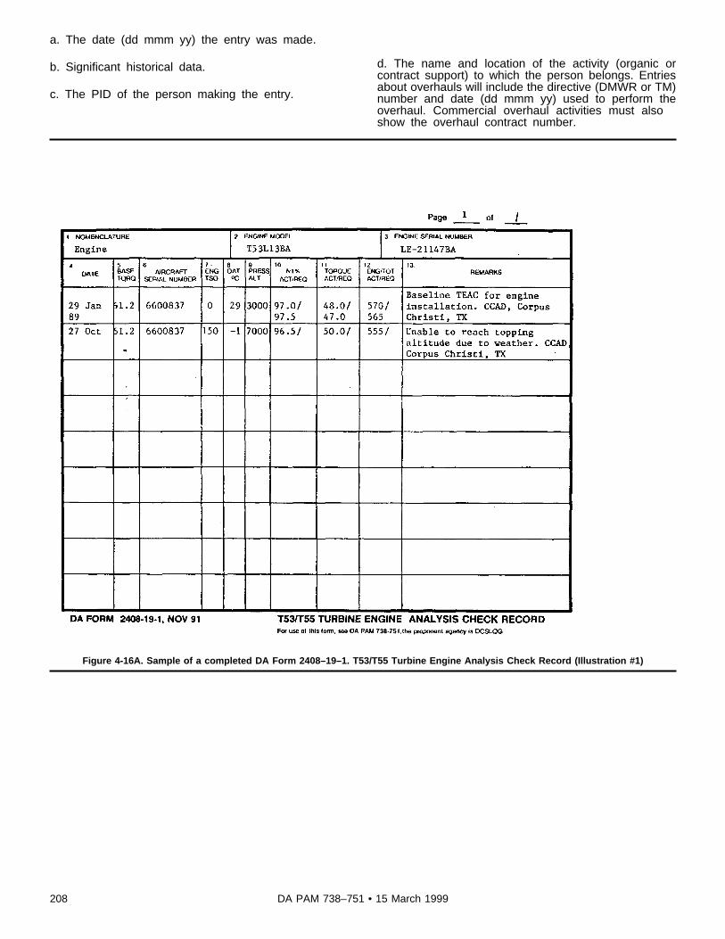
a. The date (dd mmm yy) the entry was made.
b. Significant historical data.
c. The PID of the person making the entry.
d. The name and location of the activity (organic orcontract support) to which the person belongs. Entriesabout overhauls will include the directive (DMWR or TM)number and date (dd mmm yy) used to perform theoverhaul. Commercial overhaul activities must alsoshow the overhaul contract number.
Figure 4-16A. Sample of a completed DA Form 2408–19–1. T53/T55 Turbine Engine Analysis Check Record (Illustration #1)
208 DA PAM 738–751 • 15 March 1999

Figure 4-16B. Sample of a completed DA Form 2408–19–1. T53/T55 Turbine Engine Analysis Check Record (Illustration #2)
Legend for Figure 4-16B:Preparation Instructions (by block number and title) forcompleting a DA Form 2408–19–1, T53/55 Turbine En-gine Analysis Check.
Page of . Enter the page number and the totalnumber (black lead pencil) of pages.
1. NOMENCLATURE. Enter "Engine."
2. ENGINE MODEL. Enter the engine type, model, andseries.
3. ENGINE SERIAL NUMBER. Enter the engine serialnumber.
NOTE. Columns 4 through 13 are used to show actualand required engine performance data. Enter actualflight performance data for a TEAC baseline, then com-pute the new TEAC baseline information for N1 percent,
and temperature using the engine TM -23. The requiredtorque will always be based upon the power adjustmentchart. Use the torque found on the engine data plate.
4. DATE. Enter the date (dd mmm yy) the entry wasmade or the check was completed.
5. BASE TORQ. For T53 series engines enter thetorque from the engine data plate. For T55 series en-gines leave blank.
6. AIRCRAFT SERIAL NUMBER. Enter the aircraft se-rial number (seven numerical digits).
7. ENG TSO. Enter the cumulative time, to the nearesthour, since new or last overhaul on the engine. If noneenter "0."
209DA PAM 738–751 • 15 March 1999

8. OAT oC. Enter the actual Outside Air Temperature(OAT). Do not enter compensated OAT.
9. PRESS ALT. Enter the altimeter reading with thebarometric pressure indicator set at 29.92 inches Hg.
10. N1% ACT/REQ. Enter the actual indicated N1 per-cent at the time of the check. Enter the computed per-cent corrected to the surrounding conditions based onthe reestablished standard. For example, 97.0/97.5. ForT55 series engines, when you do a Power AssuranceCheck (PAC) leave blank.
11. TORQUE ACT/REQ. Enter the actual indicatedtorque readings at the time of the check. For T53 seriesengines, enter the computed torque from the enginechart based on the torque from the engine data plate;for example, 48.0/47.0. For T55 series engines, enterthe computed torque from the engine in the applicable
TM -23. The computed torque entry is not needed dur-ing a PAC.
12. ENG/TOT ACT/REQ.
a. For T53 series engines, enter the actual indicatedEGT or Turbine Gas Temperature (TGT) at the time ofthe check in the actual side of the block. Enter the EGTor TGT corrected to ambient conditions taken from theEGT adjustment factors table in the required side of theblock; for example, 570/565.
b. For T55 series engines, enter the Power Turbine InletTemperature (PTIT) at the time of the check in the ac-tual block. Enter the PTIT corrected to ambient condi-tions taken from the PTIT adjustment factors table in therequired block.
13. REMARKS. Briefly explain why a TEAC was per-formed. Indicate whether it was a normal or a baselineTEAC.
Figure 4-17. Sample of a completed DA Form 2408–19–2. T700 Series Turbine Engine Analysis Check Record (Illustration #2)
210 DA PAM 738–751 • 15 March 1999
Legend for Figure 4-17:Preparation Instructions (by block number and title) forcompleting a DA Form 2408–19–2, T700 Series TurbineEngine Analysis Check Record.
Page of . Enter the page number and the totalnumber (black lead pencil) of pages.
1. NOMENCLATURE. Enter "Engine."
2. ENGINE MODEL. Enter the engine type, model, andseries.
3. ENGINE SERIAL NUMBER. Enter the engine serialnumber from the engine data plate.
NOTE. Blocks 4 through 12 are used to show actual andrequired engine performance data. Enter actual flightdata for a TEAC baseline, then compute the new TEACbaseline information for Ng percent and temperature.The required torque will always be based upon thepower adjustment chart. Use the torque found on theengine data plate.
4. DATE. Enter the date (dd mmm yy) that the entry wasmade or the test was completed.
5. AIRCRAFT SERIAL NUMBER. Enter the completeaircraft serial number (seven numerical digits).
6. ENGINE TIME. Enter the cumulative time since new,or last overhaul on the engine.
7. FAT oC. Enter the actual Free Air Temperature(FAT). Do not enter compensated FAT.
8. PRESS ALT. Enter the altimeter reading with thebarometric pressure indicator set at 29.92 inches Hg.
9. NG%. Enter the actual indicated NG percent at thetime of the check.
10. TORQUE
ACT. Enter the actual indicated torque readings at thetime of the check.
TTV. Enter the target torque value as computed fromthe engine chart.
ETF. Compute the engine torque factor (ETF) per TM55–2840–248–23.
11. TGT. Enter the actual indicated turbine gas tempera-ture at the time of the check.
12. REMARKS. Briefly explain why a TEAC was per-formed. Indicate whether it was a normal or baselineTEAC.
211DA PAM 738–751 • 15 March 1999

Figure 4-18. Sample of a completed DA Form 2408–19–3. Engine Component Operating Hours Record
Legend for Figure 4-18:Preparation Instructions (by block number and title) forcompleting a DA Form 2408–19–3, Engine ComponentOperating Hours Record
Page of . Enter the page number and total num-ber of pages of DA Forms 2408–19–3 for this reportperiod.
NOTE. Complete this form using ballpoint pen, typewrit-er, or computer.
1. PERIOD ENDING DATE (Julian). Enter the juliandate for the report period (the 15th of each month).
2. ORGANIZATION. Enter the name of the organizationfilling out the form.
3. UIC. Enter the Unit Identification Code of the organi-zation filling out the form.
4. LOCATION. Enter location of the aircraft when theform is filled out.
5. TELEPHONE NUMBER. Enter the duty telephonenumber (DSN or commercial) of the person filling outthe form.
6. AIRCRAFT SERIAL NO. Enter the aircraft serialnumber (seven numerical digits) that the engines inBlock 9 are installed on.
7. AIRCRAFT HOURS. Enter the current aircraft hours(rounded off to a whole number) shown on the DA Form2408–13 when the form was filled out. Do not enter "NoChange." The readings must be submitted whether theengine has been operated or not.
8. ENGINE SERIAL NO. Enter the #1 and #2 engineserial numbers for the aircraft in block 6.
212 DA PAM 738–751 • 15 March 1999

9. POS. Preprinted with a "1" for NO. 1 position engineand "2" for NO. 2 position engine.
10. LCF-1. Enter the current history recorder reading forthe Low Cycle Fatigue-1 for each engine when the formis filled out.
11. LCF-2. Enter the current history recorder reading for
the Low Cycle Fatigue-2 for each engine when the formis filled out.
12. T/TI. Enter the current history recorder reading forthe Time and Temperature Index for each engine whenthe form is filled out.
13. OP HRS. Enter the current history recorder readingfor the Operating Hours for each engine when the formis filled out.
14. HIST RCDR S/N. Enter the History Recorder SerialNumber, for each engine.
Figure 4-19A. Sample of a completed DA Form 2408–20. Oil Analysis Log (Illustration #1, Front)
213DA PAM 738–751 • 15 March 1999
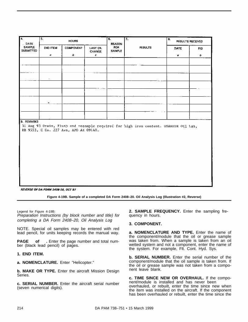
Figure 4-19B. Sample of a completed DA Form 2408–20. Oil Analysis Log (Illustration #2, Reverse)
Legend for Figure 4-19B:Preparation Instructions (by block number and title) forcompleting a DA Form 2408–20, Oil Analysis Log
NOTE. Special oil samples may be entered with redlead pencil, for units keeping records the manual way.
PAGE of . Enter the page number and total num-ber (black lead pencil) of pages.
1. END ITEM.
a. NOMENCLATURE. Enter "Helicopter."
b. MAKE OR TYPE. Enter the aircraft Mission DesignSeries.
c. SERIAL NUMBER. Enter the aircraft serial number(seven numerical digits).
2. SAMPLE FREQUENCY. Enter the sampling fre-quency in hours.
3. COMPONENT.
a. NOMENCLATURE AND TYPE. Enter the name ofthe component/module that the oil or grease samplewas taken from. When a sample is taken from an oilwetted system and not a component, enter the name ofthe system. For example, Flt. Cont. Hyd. Sys.
b. SERIAL NUMBER. Enter the serial number of thecomponent/module that the oil sample is taken from. Ifthe oil or grease sample was not taken from a compo-nent leave blank.
c. TIME SINCE NEW OR OVERHAUL. If the compo-nent/module is installed and has never beenoverhauled, or rebuilt, enter the time since new whenthe item was installed on the aircraft. If the componenthas been overhauled or rebuilt, enter the time since the
214 DA PAM 738–751 • 15 March 1999

item was overhauled or rebuild when the item was in-stalled on the aircraft. If the sample was not taken froma reportable component, the time since new on the air-frame will be entered in this block. This time will bereentered in this block on future DA Forms 2408–20until the component/module is replaced, overhauled, orrebuilt.
d. ACFT HRS LAST OIL CHANGE. Enter the aircrafthours when the oil was last changed.
e. ACFT HRS INSTALLED. Enter the aircraft hourswhen the component/module was installed on the air-craft. For hydraulic systems, enter "0."
4. DATE SAMPLE SUBMITTED. Enter the date (ddmmm yy) that the oil sample was taken.
5. HOURS.
a. END ITEM. Enter the current aircraft hours (to thenearest hour) when the oil sample was taken.
b. COMPONENT. Enter the current component/modulehours (to the nearest hour) when the oil sample wastaken. If the component/module has never been over-hauled or rebuilt, enter the time since new. If the compo-nent/module has been overhauled or rebuilt, enter thetime since last overhaul or rebuild.
c. LAST OIL CHG. Enter the component/module operat-ing hours since the last oil change (to the nearest hour).
6. REASON FOR SAMPLE. Enter "Routine" if the oilsample is scheduled and "special" if the oil sample isnot routine.
7. RESULTS. Enter the results of the laboratory analy-sis. For example, Satisfactory; Maintenance recom-mended by the laboratory; and so on. Document thefindings for the 25 Hour Chip Detector Inspection suchas the amount of debris (light or medium) and type ofdebris using description on the Oil Debris ClassificationChart. If units using the manual record keeping system,can legibly enter the results and required actions in thisblock, no entry is required in block 9, REMARKS, or ifmore room is needed continue the entry in block 9.
8. RESULTS RECEIVED.
a. Date. Enter the date (dd mmm yy) the results of thesample were received at your unit or when you receiveda phone call or message from the oil lab concerning thissample.
b. PID. The personal identifier of the person whoentered the results in block 7.
9. REMARKS. Units using the manual way of keepingrecords, will enter the location of the oil lab, when a labother then the normal lab performs the oil analysis andthe results are unsatisfactory. If the results and requiredactions can’t be legibly entered in block 7, use this blockfor continuation. For units using ULLS-A or LAS enter allAOAP laboratory requests for special oil samples ormaintenance required, by the AOAP laboratory. Precedethe entry with the date, and enter a brief statementabout the special oil sample or maintenance require-ment. Enter the location of the laboratory that did theanalysis requiring the special sample or maintenanceaction, and the PID, unit, and location of the personmaking the entry.
215DA PAM 738–751 • 15 March 1999

Figure 4-20A. Sample of a completed DA Form 2408–33–R. Meter Tracked Component Record (Illustration #1, Front)
216 DA PAM 738–751 • 15 March 1999

Figure 4-20B. Sample of a completed DA Form 2408–33–R. Meter Tracked Component Record (Illustration #2, Reverse)
217DA PAM 738–751 • 15 March 1999

Legend for Figure 4-20B:Preparation Instructions (by block number and title) forcompleting a DA Form 2408–33–R, Meter TrackedComponent Record
Page of . Enter the page number and total num-ber (black lead pencil) of pages.
1. NOMENCLATURE. Enter "Countermeasures Set."
2. NSN. Enter the National Stock Number of the coun-termeasure set.
3. PART NUMBER OR MODEL. Enter the model of thecountermeasure set.
4. SERIAL NUMBER. Enter the serial number of thecountermeasure set.
5. WUC. Enter "76F01."
6. ACFT MODEL. Enter the model (black lead pencil) ofthe aircraft the AN/ALQ-144 is installed on or assignedto.
7. ACFT SERIAL NUMBER. Enter the serial number(black lead pencil) of the aircraft the AN/ALQ-144 isinstalled on or assigned to.
8. ACFT HRS INSTALLED. Enter the aircraft hours, tothe nearest hour (black lead pencil), when the AN/ALQ-144 was installed on the aircraft. If unknown, enter thecurrent aircraft hours.
9. METER READINGS AT INST. Enter the elapsed timemeter reading (black lead pencil) when the AN/ALQ-144was installed on the aircraft. If unknown, enter the cur-rent elapsed time meter reading.
10a. NOMENCLATURE AND WUC. Enter on the topline the subcomponent name, listed in TB1–1500–341–01. Make sure you include each of theitems listed in the TB. Enter on the bottom line theproper Work Unit Code. The WorkUnit Code can befound in TB 1–1500–341–01, for each component/mod-ule.
10b. P/N AND NSN.
a. Enter on the top line the part number for each sub-component.
b. Enter on the bottom line the national stock number foreach subcomponent.
10c. COMPONENT SERIAL NUMBER OR LOCATION.Enter the serial number for each subcomponent. If thesubcomponent does not have a serial number, enter thelocation of the subcomponent.
10d. NOMEN INST HRS. Enter the elapsed time meterreading from the countermeasure set when the subcom-ponent was installed on the countermeasure set.
10e. NOMEN REMV HRS. Enter the elapsed time meterreading from the countermeasure set when the subcom-ponent was removed from the countermeasure set.
10f. COMP INST HRS. Enter the total hours on thesubcomponent, in block 10a., when it was installed onthe countermeasure set.
10g. COMP RMVL HRS. Enter the total hours on thesubcomponent, in block 10a., when it was removed fromthe countermeasure set (subtract 10e. from 10d. andadd that to 10f.).
10h. REPLACE LIFE. Enter the retirement life of thesubcomponent.
10i. REPLACEMENT DUE METER READING. Enterthe replacement time, in elapsed time meter hours,when the subcomponent is due replacement (subtract10f from 10h and add to 10d).
11. SIGNIFICANT HISTORICAL DATA. Enter any sig-nificant historical data pertaining to the countermeasureset.
Chapter 5Aviation Life Support Equipment and Aviation NightVision Goggles Forms and Records Procedures
5–1. Generala. The forms in this chapter help in tracking, by serial number;
s c h e d u l i n g ; r e c o r d i n g ; a n d m a n a g i n g m a i n t e n a n c e o p e r a t i o n s o fALSE and aviation NVGs equipment.
b. The forms show the results of maintenance checks and serv-ices, inspections, and provide a record of faults discovered duringequipment operation.
c. This chapter also tells how to use, prepare, process, and dis-pose of maintenance forms used in support of ALSE and AviationNVGs.
d. An NVG Logbook (Equipment Record Folder) is required foreach set of NVGs assigned to a unit/activity.Note. The Equipment Record Folder is shown in DA Pam 738–750. Folder,Equipment Record, NSN 7510–01–065–0166, CAGE Code 81349, P/N MIL-F-43986, 8“ by 10” , vinyl backing, 4 color camouflage pattern, transparentwindow front cover 3.125“ by 5.125” , four vinyl envelopes, two pockets,one inside front and rear covers, pockets slit from top to bottom 3.5“ fromedge. This Equipment Record Folder may also be used for ALSE equipmentrecords. The folders are available at Self-Service Supply Centers.
5–2. DA Form 2407, Maintenance Request, and DA Form2407–1, Maintenance Request Continuation SheetRefer to chapter 3 for policy/procedures, and preparation instruc-tions on how to complete DA Forms 2407 and 2407–1.
5–3. DA Form 2408–5, Equipment Modification Record.a. Purpose. This form records the requirements for, and applica-
tion of all authorized DA modifications to Aviation NVGs, listed inappendix D (see fig 5–1).Note. DA Form 2408–5 will not be used to record SOU messages/TBs. TheDA Form 2408–15, Historical Record for Aircraft, prepared for NVGs, willbe used to record SOU messages/TBs that apply.
b. Use. This form is a permanent record of MWOs for AviationNVGs listed in appendix D.
c. General instructions.(1) Do not prepare a DA Form 2408–5 for aviation NVGs until
the first MWO for the goggles has been issued.(2) DA Form 2408–5 is split into six sections: MWO Number
and Date (block 4), MWO Title (block 5), Organization ApplyingMWO (block 6), Name or PID (block 7), Date (block 8), andManhours (block 9).
(3) Entries will be made on DA Form 2408–5 when an MWO isreceived that is applicable to the NVGs. If you learn that an MWO
218 DA PAM 738–751 • 15 March 1999

has been issued and was not applied, enter the MWO requirement inblocks 4 and 5.
(4) The activity modifying the equipment will complete blocks 6,7, 8 and 9 of the form.
(5) MWO entries will be kept current. The DA Form 2408–5 isthe only historical record the owning unit has, showing the currentconfiguration of the NVGs. Take the actions below for the condi-tions and situations described.
(a) An MWO that supersedes a previous MWO. If the previousMWO has been applied, compare it with the new MWO. If morew o r k i s n e e d e d , l i n e o u t t h e o l d m o d i f i c a t i o n e n t r y a n d e n t e r“Superseded by (MWO number)” above the lined out entry, in block4. On the next open line enter the new MWO. If no other work isneeded, enter the new MWO on the next open line, and enter“PCW” in block 6. The organization, signature or PID of the personwho determined the MWO was PCW, and date will be entered inblocks 7, and 8.
(b) Canceled MWO (AR 750–10).1. If the canceled MWO has been completed and blocks 4, 5, 6,
7, 8, and 9 have been completed, take no further action. Theseentries will serve as historical events.
2. If the canceled MWO was never entered on the form, do notenter it now.
3. If the canceled MWO was entered on the form, but not com-pleted, line out the entry and enter “Canceled” and the current dateabove the lined out entry.
(c) Current MWO applied. When it is determined that an MWOhas been applied, but not recorded on DA Form 2408–5, take theactions below.
1. Complete blocks 4, 5, 6, 7, 8, and 9. Use the MWO to get thedata.
2. In block 8 show the date that the owning unit or activity foundthe MWO was applied. Enter “PCW” above the date.
3. In block 9 enter the estimated manhours shown in the MWO.4. The person who determined that the MWO was applied will
enter his or her PID, in block 7.(d) Current MWO not applied. If it is determined that an MWO
has not been applied but is recorded as applied, draw a single linethrough the entry.
d. Disposition.(1) The DA Form 2408–5 is a permanent record for aviation
NVGs, and will be placed in the first vinyl page of the logbook.(2) If the aviation NVGs are transferred to another unit or activi-
ty, the DA Form 2408–5 will be shipped with the equipment.Note. A report of MWO application will be submitted on a DA Form 2407.
5–4. DA Form 2408–15, Historical Record for Aircrafta. Purpose. This form provides historical data on aviation NVGs
throughout their service life (see fig 5–2).b. Use. This form is used to record significant historical data
such as—(1) Major repairs to aviation NVGs.(2) Accomplishment of SOF messages, SOU messages, ASAMs,
and TBs on aviation NVGs.(3) To record the replacement of image intensifier tube(s) and the
new serial number of the replacement tube(s).(4) To record Light Interference Filter (LIF) kit installation when
the AVIM maintenance section installs the kit.Note. If the NVGs are received from the factory with the LIF installed, thisentry is not required.
(5) Other information that is considered to be significant histori-cal data, and will serve a useful purpose to activities receiving theNVGs for operation, maintenance, overhaul, or rebuild.
c. Disposition.(1) This form will remain with the NVGs throughout their serv-
ice life. This form will be placed in the second vinyl page of thelogbook.
(2) If the NVGs are transferred to another unit or activity, theDA Form 2408–15 will be shipped with the goggles. The ALSE
technician will check this form for accuracy and completeness,before the NVGs are transferred.
(3) This form will remain with the NVGs until they are deter-mined to be unreparable. When the determination is made that theNVGs are no longer reparable, the form will be destroyed.
5–5. DA Form 2408–21, Life Raft Inspection Record.a. Purpose. This form provides a record of the life raft inventory
and maintenance inspections (see fig 5–3).b. Use. This form is used—(1) As an inventory record of installed components.(2) To show the completion, and next due date of inspections per
TM 5–4220–202–14.c. General instructions.(1) For one man life rafts, complete only blocks 1 through 4, 6,
11, 22a, b, c, and d.(2) Check multiplace raft, with accessory containers installed per
instructions in TM 5–4220–202–14.d. Disposition. Destroy the form 6 months after the last inspec-
tion/service was recorded in block 22.
5–6. DA Form 2408–22, Helmet and Oxygen Mask/Connector Inspection Record.
a. Purpose. This form provides a record of helmet, oxygen mask/connector, and NVG visor inspections and maintenance performed(see fig 5–4).
b. Use. This form is used to record—(1) Completed helmet inspections per TM 10–8415–206–12&P.( 2 ) C o m p l e t e d o x y g e n m a s k / c o n n e c t o r i n s p e c t i o n s p e r T M
55–1660–247–12.(3) Completed visor inspections and continuity checks per TM
11–5855–263–23&P.(4) Repairs made to the helmet, visor, and oxygen mask/connec-
tors.(5) Annual helmet and oxygen mask fittings.(6) The NVG visor 120 day inspection.c. General instructions. Maintain this form in the ALSE shop
separate from the NVG records.d. Disposition. Destroy the form 6 months after the last inspec-
tion/service was recorded, in block 9 or 10.
5–7. DA Form 2408–23, Survival Radio/EmergencyLocation Transmitter Inspection Record.
a. Purpose. This form provides a record of inspections and main-tenance needed and completed for the survival radio/emergencylocation transmitter (ELT). (see fig 5–5).
b. Use. This form is used to—(1) Provide a record of completed inspections, and shows when
the next inspections are due per TM 11–5820–800–13&P.(2) Identify the battery installed in the ELT.(3) Record significant historical data, SOF and SOU messages,
ASAMs, TBs, and so forth.c. Disposition. Destroy the form 6 months after the last inspec-
tion and service was recorded in block 9.
5–8. DA Form 2408–24, Survival Kit Inspection andMaintenance Record.
a. Purpose. This form provides a record of all inspections andmaintenance needed and completed for the survival kit (see fig 5–6).
b. Use. This form is used to—(1) Record completed inspections and show when the next in-
spection is due per TM 55–1680–317–23.(2) List all components or items installed in the survival kit.(3) Record faults found during inspections, and corrective action
taken.(4) Record expiration dates and lot numbers for installed ammu-
nition and flares.c. Disposition. Destroy the form 6 months after the last inspec-
tion and service was recorded in block 12.
219DA PAM 738–751 • 15 March 1999

5–9. DA Form 2408–25, Mesh Net Survival Vest InspectionRecord.
a. Purpose. This form provides a record of all inspections andmaintenance needed and completed for the Mesh Net Survival Vest(see fig 5–7).
b. Use. This form is used to—(1) Record completed inspections and show when the next in-
spections are due per TM 55–1680–317–23.(2) List all components or items installed or attached to the vest.(3) Identify, by serial number, the installed or assigned emer-
gency radio and light marker.(4) List the type and lot number of any installed munitions.(5) List the type, lot number and expiration date of the first aid
components.c. Disposition. Destroy the form 6 months after the last inspec-
tion or service was recorded in block 9.
5–10. DA Form 2408–26, Life Preserver InspectionRecord.
a. Purpose. This form provides a historical record of all lifepreserver inspections and maintenance needed and completed (seefig 5–8).
b. Use. This form is used to —(1) Record completed inspections, and show when the next in-
spection is due per TM 5–4220–202–14.( 2 ) R e c o r d s i g n i f i c a n t h i s t o r i c a l i n f o r m a t i o n o n l i f e p r e s e r v e r
units.(3) Show a record of completed CO2 inflation tests.c. Disposition. Maintain this form in the ALSE shop. Destroy the
form 6 months after the last inspection or service was recorded inblock 11.
5–11. DA Form 2408–27, Life Preserver Data.a. Purpose. This form provides a record of inspection and infla-
tion tests needed for the life preserver (see fig 5–9).b. Use. This form is used to record—(1) Completed C02 inflation tests, and show when the next infla-
tion test is due per TM 5–4220–202–14.(2) Completed life preserver inspections and show when the next
inspection is due per TM 5–4220–202–14.(3) Historical data for each life preserver.c. Special instructions.(1) Make sure that DA Form 2408–26 is updated when DA Form
2408–27 is changed.(2) Attach the DA Form 2408–27 to the life preserver.d. Disposition. This form is used only to record inflation tests
and may be replaced as necessary. Destroy the form 6 months afterthe last inspection or service was recorded in block 6.
5–12. DA Form 2408–28, Oxygen Console Service Record.a. Purpose. This form provides a record of the oxygen system
and will be affixed to the console. A second copy of the form willbe used as a shop record (see fig 5–10).
b. Use. This form is used to—(1) Serve as an inventory of installed components.(2) Record completion and next due date of inspections per TM
55–1660–247–12.(3) Record the servicing, repair, or modification of the unit.c. Disposition. Destroy the oxygen console copy of the form 1
year after the last inspection was recorded in block 7.
5–13. DA Form 2408–29, Anti-Exposure CoverallsInspection Record.
a. Purpose. This form provides a record of inspections and main-tenance needed and completed for the anti-exposure coveralls (seefig 5–11).
b. Use. This form is used to record—(1) Completed inspections, and when the next inspection is due
per TM 10–8475–202–13.
( 2 ) F a u l t s f o u n d d u r i n g i n s p e c t i o n s , a n d a l l c o r r e c t i v e a c t i o ntaken.
c. Disposition. Destroy the form 6 months after the last inspec-tion or service was recorded in block 6.
5–14. DA Form 2408–30, NVG Inspection and MaintenanceRecord.
a. Purpose. This form provides a record of all faults found duringassembly, preoperational checks, preventive maintenance checks andservices, special inspections, and operation of aviators NVG system(see fig 5–12).
b. Use. This form is used for aviation night vision goggles, AN/PVS-5 and AN/AVS-6 series. It is used to—
(1) Record operator remarks or faults detected and dates found.(2) Record action taken to correct faults and dates corrected.(3) Record condition status symbols of NVGs.(4) Record completed maintenance, services, checks, and inspec-
tions, and dates completed.Note. There is no requirement to document “Preoperational check due” or“Operators check due” on DA Form 2408–30.
(5) Shows when the next scheduled inspection is due.( 6 ) R e c o r d s p e c i a l i n s p e c t i o n s . F o r e x a m p l e ; d i s t o r t i o n
evaluations.c. Special instructions for the operator.(1) Before using NVGs in the aircraft, perform a preoperational
check to determine if the equipment is ready to use.(2) Review the DA Form 2408–30 to ensure that the next sched-
uled maintenance inspection is not overdue, and check the conditionstatus of the NVG to assure that equipment is ready for use.
(3) Distortion evaluation completion requires the signatures oftwo experienced ANVIS/NVG pilots to be entered.
(4) It is recommended that units retain the DA Form 2408–30while NVGs are at the AVIM unit for repair or inspection. AfterNVGs are returned from a maintenance facility, the owning unit willcomplete the DA Form 2408–30, PART II - CORRECTING IN-FORMATION, ACTION section, by entering a short description ofthe action taken from the DA Form 2407, after verifying the workwas inspected. After the short description, the maintainer will enterhis or her signature. When the fault is a red “X/“ or circled red “X”the TI will ensure a satisfactory MOC is completed, and enter “InspOK” after the maintainer’s signature, and enter his or her signaturein the TIPID block.
(5) Commanders at the AVUM level may authorize the NVGmaintainer to also be the TI. In unit/activities where the commanderhas designated the maintainer to perform TI duties the maintainer/TImust sign after the corrective action, as well as the TIPID blockwhen the fault is a red “X” or circle red “X.” Paragraph 1–9b ofthis pamphlet applies to all unit/activities that perform other thanAVUM level work.Note. Three month PMCS consists of inspections, checks, and services of theNVG and power pack, high/low resolution test, and for ANVIS an infinityfocus check.
d. General instructions.(1) Maintain the current DA Form 2408–30 in the NVG carrying
case. Fold the form to fit inside the case. The DA Form 2408–30will be maintained by the owning unit. When the form is completelyfilled, close it out by entering “CF” in the CORRECTING INFOR-MATION block of all uncorrected faults. The person carrying for-ward the entry to the new form will sign his or her name after the“CF.” Enter the date that the fault was carried forward in the DATEblock. Initiate a new DA Form 2408–30, enter in block 6 (NEXTINSPECTION DUE) when the next scheduled inspections (3 monthand 6 month) are due, and in PART I - FAULT INFORMATIONblocks reenter the fault as it was originally entered on the old form.
(2) Enter only one fault or remark in each PART I - FAULTINFORMATION Block. There are a total of five blocks on each DAForm 2408–30.
(3) Make hand printed entries in black lead pencil, or a type-writer may be used. Use only a red lead pencil or ballpoint pen with
220 DA PAM 738–751 • 15 March 1999

red ink for status symbols. The commander or designated represent-atives may use blue or black ballpoint pen to clear red “X” or circlered “X” entries. The use of transparent tape is authorized for use inblock 6. Tape must be of the type you can print on with a pencil.
(4) Once a status symbol is in the STATUS block, it will not beerased or changed even if entered in error (para 1–9). The personwho corrects a red dash or red diagonal fault will enter their lastname initial over the status symbol. A red “X” or circled red “X”status symbol will be initialed over only by a qualified designatedrepresentative.
(5) The person who finds a fault will enter a short description ofthe fault, maintenance check, service, or inspection in the FAULTINFORMATION Block and sign his or her name behind the entry.
(6) If more space is needed in the FAULT INFORMATIONblock to enter a fault/remark then enter “Continued” or “Cont.” onthe last line of the FAULT INFORMATION block and continue thefault/remark in the next open FAULT INFORMATION block.
(7) When corrective action has been taken to correct the fault,deficiency, condition, incorrect entry, or directive (such as, SOUmessages, TBs or MWOs), and components or other repair parts areremoved and reinstalled, or replaced, the person making the correc-tive action will enter the action taken in PART II - CORRECTINGINFORMATION block. Using words or phrases, such as, “applied,”“ tested,” “installed,” “serviced,” “replaced,” “ repaired,” “adjusted,”or “erroneous entry” with other brief information, to describe the
corrective action, will be sufficient. If you use one or more words todescribe action taken, or use authorized abbreviations, it will not beconsidered in error. DO NOT use the word “Corrected.”
(8) Upon completion of the corrective action, the person makingthe corrective action will sign his or her name and place their lastname initial over the red dash or diagonal symbol in the STATUSblock of the FAULT INFORMATION block. To clear a Red “X” orCircled Red “X” symbol, the completed action must be inspected bya designated representative per paragraph 1–9.
(9) The person completing the corrective action on the DA Form2408–30 that calls for additional entries on historical forms or re-cords, such as, DA Forms 2408–5 or 2408–15, will be responsiblefor entries on the historical forms.
e. Disposition. Maintain the current DA Form 2408–30 in theNVG carrying case until the form is completely filled. The closedout form will be filed in the third vinyl page of the logbook. Alladditional closed out forms will be kept in the fourth vinyl page ofthe logbook for 6 months from the date of the last entry on theform.
5–15. DD Forms 1574/1574–1, 1575/1575–1, 1576/1576–1,1577/1577–1, and 1577–2/1577–3, Tags/Labels (Material).Refer to chapter 3, for policy/procedures and preparation instruc-tions on how to complete the tags/labels.
221DA PAM 738–751 • 15 March 1999

Figure 5-1. Sample of a completed DA Form 2408–5, Equipment Modification Record.
Legend for Figure 5-1:Preparation Instructions (by block number and title) forcompleting a DA Form 2408-5, Equipment ModificationRecord, when used for Night Vision Goggles
Page of . The page number and total number(black lead pencil) of pages.
1. NOMENCLATURE. Enter the item name (for exam-ple, ANVIS or NVG).
2. MODEL. Enter the model of the NVG (for example,AN/PVS-5, AN/AVS-6(V)1, or GM-6(V)1).
3. AIRCRAFT SERIAL NUMBER. Enter the serial num-ber of the NVGs.
4. MWO NUMBER AND DATE
a. Enter the MWO number in the upper part of thisblock. The activity applying the MWO will normally com-plete this block. MWO’s not applied will be entered bythe person that determines that MWO was not applied.
b. Enter the MWO publication date (dd mmm yy), priorityfor the MWO ("E" for Emergency, "U" for Urgent, or "R"for Routine), and the maintenance level responsible forapplication of the MWO ("O" for AVUM, "F" for AVIM, or"D" for Depot) in the bottom part of this block.
5. MWO TITLE. Enter the MWO abbreviated title.
6. ORGANIZATION APPLYING MWO. Enter the UIC orthe name of the organization that applied the MWO, ordetermined that the MWO was previously applied. If anMWO is issued but not applied, enter the date the MWOmust be applied by (black lead pencil). Erase the datewhen the MWO is applied.
NOTE. Enter the MWO as overdue on DA Form
222 DA PAM 738–751 • 15 March 1999

2408–30 if the MWO has not been applied by the duedate.
7. NAME OR PID. The person who certifies the MWOapplication will enter their PID.
8. DATE. Enter the date (dd mmm yy) that the MWOwas applied.
9. MANHOURS. Enter the actual manhours it took toapply the MWO, to the nearest tenth of an hour, includ-ing the technical inspection.
Figure 5-2. Sample of a completed DA Form 2408–15, Historical Record for Aircraft
Legend for Figure 5-2:Preparation Instructions (by block number and title) forcompleting a DA Form 2408–15, Historical Record forAircraft, when used for Night Vision Goggles.
Page of . Enter the page number and the totalnumber (black lead pencil) of pages.
1. AIRCRAFT MODEL. Enter the model of the NVGs.For example, AN/PVS-5 or AN/AVS-6(v)1.
2. NOMENCLATURE. Enter the item name, for exam-ple, Night Vision Goggles or ANVIS.
3. AIRCRAFT SERIAL NUMBER. Enter the serial num-ber of the NVGs.
4. REMARKS.
a. Record any significant historical data about theNVGs.
b. The historical data entries should include completedata on SOU messages, TBs, major repairs, replace-ment of image intensifier tubes with serial numbers, onetime inspections, and installation of the LIF kit wheninstalled by AVIM.
5. ORGANIZATION LOCATION. Enter the name of theunit or organization and location of the unit that in-spected, repaired, or overhauled the NVGs.
223DA PAM 738–751 • 15 March 1999

6. DATE. Enter the date (dd mmm yy) the action wascompleted.
7. ENTRY NUMBER. Manual Record keeping system,
leave this block blank. ULLS-A users, entry is automati-cally entered.
8. PID. The person who verifies the maintenance actionwas completed or makes an entry will enter his or herPersonal Identifier in this block.
Figure 5-3A. Sample of a completed DA Form 2408–21, Life Raft Inspection Record (Illustration #1, Front)
224 DA PAM 738–751 • 15 March 1999

Figure 5-3B. Sample of a completed DA Form 2408–21, Life Raft Inspection Record (Illustration #2, Reverse)
Legend for Figure 5-3B:Preparation Instructions (by block number and title) forcompletion of a DA Form 2408-21, Life Raft InspectionRecord
Page . Enter the page number.
1. RAFT TYPE. Enter the type of raft.
2. RAFT SERIAL NO. Enter the raft serial number. If theraft does not have a serial number, enter the locallyassigned identification number.
3. ACCESSORY KIT TYPE. Enter the type of accessorysurvival kit that is installed with the raft.
4. KIT NO. Enter the serial number or locally assignedidentification number of the accessory kit.
5. LOCATION. Enter where the raft assembly is physi-cally located (black lead pencil). For example, C-12Aaircraft SN 7902468.
6. RAFT MANUFACTURER. Enter the manufacturer’sname.
7. FLARE LOT NUMBER. Enter the lot number of theinstalled flares.
8. RADIO/PLB TYPE. Enter the type of radio or PLBinstalled.
9. SDU. Enter the type of SDU installed.
10. CO2 HYDRO TEST DUE. Enter the date (dd mmmyy, black lead pencil) that the CO2 cylinder is due ahydrostatic test.
11. RAFT DOM. Enter the date (dd mmm yy) the raftwas manufactured.
12. DATE FLARES INSTALLED. Enter the date (ddmmm yy, black lead pencil) the flares were installed inthe raft.
13. RADIO/PLB BATTERY EXPIRES. Enter the date(dd mmm yy, black lead pencil) that the radio or PLBbattery is due replacement.
14. SDU BATTERY EXPIRES. Enter the expiration date(dd mmm yy, black lead pencil) of the SDU battery.
225DA PAM 738–751 • 15 March 1999
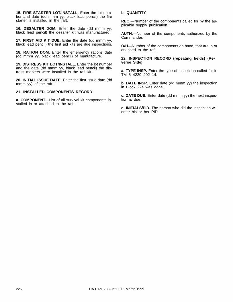
15. FIRE STARTER LOT/INSTALL. Enter the lot num-ber and date (dd mmm yy, black lead pencil) the firestarter is installed in the raft.
16. DESALTER DOM. Enter the date (dd mmm yy,black lead pencil) the desalter kit was manufactured.
17. FIRST AID KIT DUE. Enter the date (dd mmm yy,black lead pencil) the first aid kits are due inspections.
18. RATION DOM. Enter the emergency rations date(dd mmm yy, black lead pencil) of manufacture.
19. DISTRESS KIT LOT/INSTALL. Enter the lot numberand the date (dd mmm yy, black lead pencil) the dis-tress markers were installed in the raft kit.
20. INITIAL ISSUE DATE. Enter the first issue date (ddmmm yy) of the raft.
21. INSTALLED COMPONENTS RECORD
a. COMPONENT—List of all survival kit components in-stalled in or attached to the raft.
b. QUANTITY
REQ.—Number of the components called for by the ap-plicable supply publication.
AUTH.—Number of the components authorized by theCommander.
O/H—Number of the components on hand, that are in orattached to the raft.
22. INSPECTION RECORD (repeating fields) (Re-verse Side):
a. TYPE INSP. Enter the type of inspection called for inTM 5–4220–202–14.
b. DATE INSP. Enter date (dd mmm yy) the inspectionin Block 22a was done.
c. DATE DUE. Enter date (dd mmm yy) the next inspec-tion is due.
d. INITIALS/PID. The person who did the inspection willenter his or her PID.
226 DA PAM 738–751 • 15 March 1999

Figure 5-4. Sample of a completed DA Form 2408–22, Helmet and Oxygen Mask/Connector Inspection Record
Legend for Figure 5-4:Preparation Instructions (by block number and title) forcompletion of a DA Form 2408–22, Helmet and OxygenMask/Connector Inspection Record
Page of . Enter the page number and total num-ber (black lead pencil) of pages.
1. NAME. Enter the name of the person the helmet isassigned to. For float visor enter the unit’s designatednumber for the visor.
2. RANK. Enter the rank of the person the helmet isassigned to. For float visor leave blank.
3. ORGANIZATION. Enter the individual’s organization.For float visor leave blank.
4. ANNUAL FITTING. Enter the date (dd mmm yy) ofthe annual fitting of the helmet and oxygen mask. Forfloat visor leave blank.
5. HELMET TYPE. Enter the helmet type. For float visorleave blank.
6. SIZE. Enter the helmet size. For float visor leaveblank.
7. OXYGEN MASK TYPE. Enter the type of the oxygenmask if installed. Enter ANVIS for the visor type.
8. SIZE. Enter the size of oxygen mask. For float visorleave blank.
9. HELMET AND OXYGEN MASK/CONNECTOR IN-SPECTION RECORD.
a. INSPECTION DATE. Enter the date (dd mmm yy) ofthe last inspection of the helmet, visor, or oxygen mask.
b. REMARKS. Enter faults for either helmet, visor, and/or the oxygen mask. If no faults enter "Insp OK." Enterin block 10, if maintenance is needed.
c. NAME. The person who actually did the inspectionwill enter his or her PID.
d. NEXT INSPECTION DUE. Enter the date (dd mmmyy) the next inspection is due.
227DA PAM 738–751 • 15 March 1999

10. HELMET AND MASK REPAIR DATA.
a. DATE. Enter the date (dd mmm yy) the manufacture,visor installation, or repair was completed.
b. INITIALS. The person who did the maintenance workwill enter his or her PID.
c. COMPONENT REPAIR/REPLACE. Enter corrective
action taken and list all repair parts/components usedduring the repair(s).
11. TECHNICAL INSPECTION. (See TM10–8415–206–13.)
a. DATE. Enter date (dd mmm yy) of the technical in-spection.
b. INITIALS. The person doing the inspection will enterhis or her PID.
c. REMARKS. Enter any significant historical informa-tion.
Figure 5-5. Sample of a completed DA Form 2408–23, Survival Radio/Emergency Locator Transmitter Inspection Record
Legend for Figure 5-5:Preparation Instructions (by block number and title) forcompletion of a DA Form 2408–23, Survival Radio/Emergency Locator Transmitter Inspection Record
Page of . Enter the page number and total num-ber (black lead pencil) of pages.
1. RADIO TYPE. Enter type of survival radio or emer-gency location transmitter. For example, AN-PRC-90,URC-10, and so forth.
2. RADIO SERIAL NO/MANUFACTURE DATE. Enterthe survival radio or ELT serial number, and date (ddmmm yy) of manufacture.
3. NATIONAL STOCK NUMBER. Enter the NSN of thesurvival radio or ELT.
228 DA PAM 738–751 • 15 March 1999

4. TECHNICAL MANUAL. Enter the reference TM num-ber.
5. BATTERY TYPE. Enter the type of battery installed.
6. BATTERY SERIAL NUMBER. Enter the battery se-rial number (black lead pencil).
7. BATTERY LOT NUMBER. Enter the lot number (bla-ck lead pencil) of the battery installed.
8. BATTERY MANUFACTURE DATE. Enter the date(dd mmm yy, black lead pencil) the battery was manu-factured.
9. INSPECTION RECORD. (See TM 11–5820–800–13& P)
a. DUE DATE. Enter the date (dd mmm yy) the nextinspection is due.
b. TYPE INSPECTION. Enter the type of inspectioncompleted.
c. DATE INSPECTED. Enter the date the inspectionwas completed.
d. INITIALS. The person making the inspection will puthis or her PID here.
e. REMARKS. Enter any significant historical informa-tion, including major repairs of the equipment.
Figure 5-6A. Sample of a completed DA Form 2408–24, Survival Kit Inspection and Maintenance Record (Illustration #1, Front)
229DA PAM 738–751 • 15 March 1999
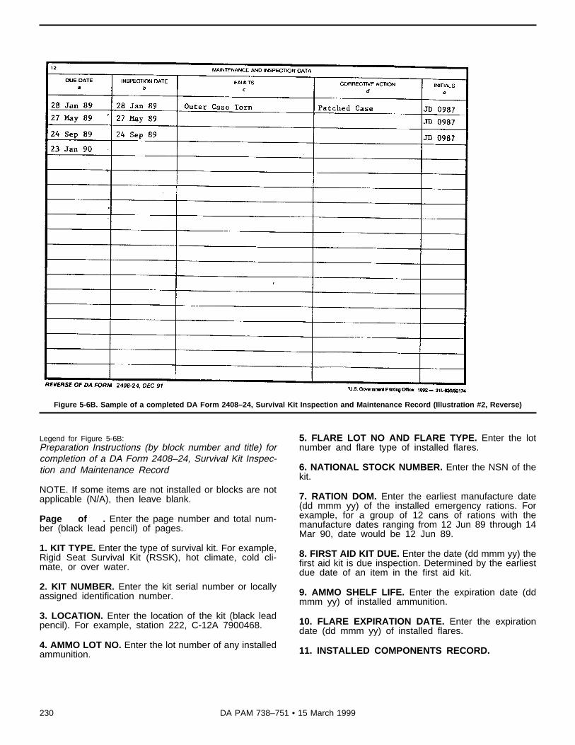
Figure 5-6B. Sample of a completed DA Form 2408–24, Survival Kit Inspection and Maintenance Record (Illustration #2, Reverse)
Legend for Figure 5-6B:Preparation Instructions (by block number and title) forcompletion of a DA Form 2408–24, Survival Kit Inspec-tion and Maintenance Record
NOTE. If some items are not installed or blocks are notapplicable (N/A), then leave blank.
Page of . Enter the page number and total num-ber (black lead pencil) of pages.
1. KIT TYPE. Enter the type of survival kit. For example,Rigid Seat Survival Kit (RSSK), hot climate, cold cli-mate, or over water.
2. KIT NUMBER. Enter the kit serial number or locallyassigned identification number.
3. LOCATION. Enter the location of the kit (black leadpencil). For example, station 222, C-12A 7900468.
4. AMMO LOT NO. Enter the lot number of any installedammunition.
5. FLARE LOT NO AND FLARE TYPE. Enter the lotnumber and flare type of installed flares.
6. NATIONAL STOCK NUMBER. Enter the NSN of thekit.
7. RATION DOM. Enter the earliest manufacture date(dd mmm yy) of the installed emergency rations. Forexample, for a group of 12 cans of rations with themanufacture dates ranging from 12 Jun 89 through 14Mar 90, date would be 12 Jun 89.
8. FIRST AID KIT DUE. Enter the date (dd mmm yy) thefirst aid kit is due inspection. Determined by the earliestdue date of an item in the first aid kit.
9. AMMO SHELF LIFE. Enter the expiration date (ddmmm yy) of installed ammunition.
10. FLARE EXPIRATION DATE. Enter the expirationdate (dd mmm yy) of installed flares.
11. INSTALLED COMPONENTS RECORD.
230 DA PAM 738–751 • 15 March 1999

a. COMPONENT. Enter the name of each item/compo-nent installed in the survival kit.
b. QUANTITY REQ. Enter the number of componentscalled for in the supply publication that applies.
AUTH. Enter the number of components prescribed bythe commander to perform the mission.
O/H. Enter the number of components that are on handin the survival kit.
12. MAINTENANCE AND INSPECTION DATA. (Re-verse Side)
a. DUE DATE. Enter the next inspection due date (ddmmm yy).
b. INSPECTION DATE. Enter the date (dd mmm yy) ofthe last inspection.
c. FAULTS. Enter the faults found during the inspection.
d. CORRECTIVE ACTION. Enter the actions taken tocorrect the faults.
e. INITIALS. The person performing the inspection and/or repairs will enter his or her PID.
Figure 5-7A. Sample of a completed DA Form 2408–25, Mesh Net Survival Vest Inspection Record (Illustration #1, Front)
231DA PAM 738–751 • 15 March 1999

Figure 5-7B. Sample of a completed DA Form 2408–25, Mesh Net Survival Vest Inspection Record (Illustration #2, Reverse)
Legend for Figure 5-7B:Preparation Instructions (by block number and title) for completion of a
DA Form 2408–25, Mesh Net Survival Vest Inspection Record
NOTE. If some items are not installed or blocks are notapplicable (N/A), leave blank.
Page of . Enter the page number and total number(black lead pencil) of pages.
1. NAME. Enter the name of the person to whom thevest is issued.
2. RANK. Enter the rank of the person the vest is issuedto.
3. LOCATION. Enter where the survival vest is located.For example, the unit to which the aircraft is assigned.
4. SIZE. Enter the size of the survival vest.
5. INSTALLED COMPONENT RECORD.
a. NOMENCLATURE. Enter the name of each item/component installed in or attached to the vest.
b. REQ. Enter number of items called for by supplymanuals that apply.
c. AUTH. Enter number of items prescribed by the Com-mander.
d. ON HAND. Enter the number of the items presentlyinstalled in the vest.
6. RADIO AND BATTERY.
a. TYPE. Enter type of radio, light marker, or other itemsinstalled in the vest with batteries.
b. SERIAL NUMBER. Enter serial number of radio, lightmarker, or other items and the year of manufacture ofthe equipment.
c. BATTERY DOM. Enter the date (dd mmm yy) ofmanufacture of the installed battery.
232 DA PAM 738–751 • 15 March 1999

7. WEAPON/AMMO.
a. TYPE. Enter type weapon/ammo installed in survivalvest.
b. SERIAL NUMBER. Enter serial number of theweapon installed.
c. AMMO LOT NO. Enter the Lot Number and date (ddmmm yy) of manufacture of the ammo.
8. PYROTECHNICS.
a. Type. Enter the type of pyrotechnics installed in sur-vival vest. For example, signal kit, M1-185, M-13, andso on.
b. LOT NUMBER/DATE. Enter lot number of the pyro-technics and date (dd mmm yy) of manufacture.
c. DOI. Enter date (dd mmm yy) of issue. If not availa-ble, use date (dd mmm yy) the pyrotechnics wereinstalled in the vest.
9. FIRST AID COMPONENTS.
a. TYPE. Enter the type of each medical item in the firstaid kit.
b. LOT NUMBER. Enter the lot number of each medicalitem in the first aid kit.
c. EXPIRATION DATE. Enter the expiration date ofeach medical item in the first aid kit.
10. INSPECTION DATA. (Reverse Side) (See TM55–1680–317–23, TM 11–5820–640–15, TM11–5820–767–12, TM 11–5820–13&P, TM9–1300–385–1, and TM 9–1300–385–2)
a. TYPE OF INSPECTION. Enter type of inspection per-formed. For example, initial, modification, 120 days, andso on.
b. DATE DUE. Enter the date (dd mmm yy) the inspec-tion is due.
c. DATE COMPLETED. Enter the date (dd mmm yy)the inspection is completed.
d. INITIALS OR PID. Enter the PID of the person whocompleted the inspection.
Figure 5-8A. Sample of a completed DA Form 2408–26, Life Preserver Inspection Record (Illustration #1, Front)
233DA PAM 738–751 • 15 March 1999

Figure 5-8B. Sample of a completed DA Form 2408–26, Life Preserver Inspection Record (Illustration #2, Reverse)
Legend for Figure 5-8B:Preparation Instructions (by block number and title) forcompletion of a DA Form 2408–26, Life Preserver In-spection Record
1. TYPE. Enter type of flotation unit, for example, LPU-2.
2. SERIAL NUMBER. Enter the serial number of the lifepreserver. If not available print the locally assigned iden-tification number and the date (dd mmm yy) of manufac-ture.
3. LOCATION. Enter the location of the life preserver,for example, individual aircraft or storage area.
4. FUNCTIONAL TEST DUE. Enter the date (dd mmmyy, black lead pencil) CO2 inflation test is due per TM5–4220–202–14.
5. DATE PACKED. Enter the date (dd mmm yy, blacklead pencil) the flotation unit was packed.
6. LEFT CELL SERIAL NUMBER. Enter serial numberof the left cell.
7. LEFT CELL MANUFACTURER. Enter the name ofthe manufacturer for the left cell.
8. RIGHT CELL SERIAL NUMBER. Enter serial numberof the right cell.
9. RIGHT CELL MANUFACTURER. Enter the name ofthe manufacture for the right cell.
10. ISSUE RECORD.
a. DATE ISSUED. Enter the date (dd mmm yy) of issueto the current user.
b. LOCATION. Enter where life preserver cells weretested and checked.
11. INSPECTION RECORD. (See TM 5–4220–202–14)
a. DUE DATE. Enter the date (dd mmm yy) the lifepreserver’s next inspection is due.
b. DATE INSPECTED. Enter the date (dd mmm yy) ofthe last inspection.
234 DA PAM 738–751 • 15 March 1999

c. INITIALS OR PID. The person marking the inspectionwill enter his or her PID.
12. REMARKS. (Reverse Side.) Enter any significant
historical data, including major repair of the life preser-ver, date of completion, and the name and location ofthe activity that did the maintenance work. Person mak-ing the entry will enter his or her PID, organization, andlocation.
235DA PAM 738–751 • 15 March 1999

Figure 5-9A. Sample of a completed DA Form 2408–27, Life Preserver Data (Illustration #1, Front)
236 DA PAM 738–751 • 15 March 1999

Figure 5-9B. Sample of a completed DA Form 2408–27, Life Preserver Data (Illustration #2, Reverse)
Legend for Figure 5-9B:
Preparation Instructions (by block number and title) forcompletion of a DA Form 2408–27, Life Preserver Data.
1. TYPE. Enter the type of flotation unit. For example,LPU-2.
2. ID NO. Enter the serial number of the life preserver. Ifnot available, print the locally assigned identificationnumber.
3. MANUFACTURER AND DATE. Enter the manufac-turer and date (dd mmm yy) of manufacture.
a. PACK AND HARNESS. Enter the type of pack andharness that applies.
b. R CELL S/N — MFG. Enter serial number of the rightcell, name of manufacturer, and date of manufacture.
c. L CELL S/N — MFG. Enter serial number of the leftcell, name of manufacturer, and date of manufacture.
4. REMARKS. Enter any significant historical data, suchas, harness repair, modification, and so on.
5. CO2 INFLATION TEST.
TESTED BY. The person performing the inflation testwill sign his or her name.
DATE. Enter the date (dd mmm yy) the inflation testwas done.
6. INSPECTION RECORD (Reverse Side).
a. DATE INSP. Enter the date (dd mmm yy) the lifepreserver was inspected.
b. DATE DUE. Enter the date (dd mmm yy) the nextinspection is due on the life preserver.
c. INSPECTOR’S SIGNATURE AND RANK. The in-spector who did the inspection will enter his or her PIDand rank.
237DA PAM 738–751 • 15 March 1999
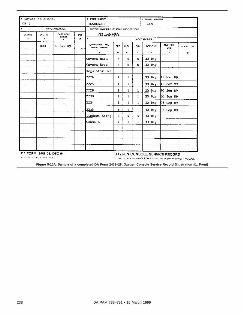
Figure 5-10A. Sample of a completed DA Form 2408–28, Oxygen Console Service Record (Illustration #1, Front)
238 DA PAM 738–751 • 15 March 1999

Figure 5-10B. Sample of a completed DA Form 2408–28, Oxygen Console Service Record (Illustration #2, Reverse)
Legend for Figure 5-10B:Preparation Instructions (by block number and title) forcompletion of a DA Form 2408–28, Oxygen ConsoleService Record
1. CONSOLE TYPE OR MODEL. Enter the consolemodel number, name, or type.
2. PART NUMBER. Enter the console part number,from the data plate, on the console.
3. SERIAL NUMBER. Enter the console serial number,from the data plate, on the console.
4. OXYGEN SERVICE.
a. STATUS. Enter the status; for example, red diagonal,Red "X," and so on. When the discrepancy is clearedthe person doing the work will place last name initialover status symbol. When the status symbol is a red "X"or circle red "X" the person that makes the quality con-trol inspection will place last name initial over the statussymbol.
b. SYS-PSI. Enter the pounds per square inch readingafter servicing.
c. DATE CERT SVC BL. Enter date (dd mmm yy) theconsole is filled to capacity and in a totally serviceablecondition.
d. PID. The person checking or performing oxygen serv-ice will enter his or her PID.
5. OXYGEN CYLINDER HYDROSTATIC TEST DUE.Enter the date (dd mmm yy, black lead pencil) the oxy-gen cylinder(s) must be removed for hydrostatic test.
6. ACCESSORIES.
a. COMPONENT AND SERIAL NUMBER. List all com-ponents and their serial numbers for the oxygen system.
b. REQ. Enter the number of components called for bythe supply manual.
c. AUTH. Enter the number called for by the Command-er.
d. O/H. Enter the number of components presently onhand.
239DA PAM 738–751 • 15 March 1999

e. INSP CYCL. Enter the frequency of the inspectioncycle, for example, 30 day (see TM 55–1660–243–12).
f. TIME CHG DUE. Enter the date (dd mmm yy) thecomponent’s operational time will expire and will be re-moved from service. If N/A leave blank.
g. LOCAL USE. Use this column as directed locally.
7. INSPECTION DATA. (Reverse Side) (See TM55–1660–243–12).
a. TYPE INSP/TEST. Enter the type of inspection ortest. For example, periodic, oxygen flow test, or leaktest.
b. DATE INSP. Enter the date (dd mmm yy) of inspec-tion or test completion.
c. DATE DUE. Enter the date (dd mmm yy) the nextinspection or test is due.
d. INITIALS OR PID. The person who did the inspectionor test will enter his or her PID.
8. REPAIR/MWO DATA.
a. DISCREPANCY. Enter a brief description of the faultor MWO to be applied.
b. DATE CORR. Enter the date (dd mmm yy) the faultwas fixed and cleared, or MWO was applied.
c. INITIALS OR PID. The person who did the mainte-nance work or the MWO and form entries, will enter hisor her PID.
Figure 5-11A. Sample of a completed DA Form 2408–29, Anti-Exposure Coveralls Inspection Record (Illustration #1, Front)
240 DA PAM 738–751 • 15 March 1999
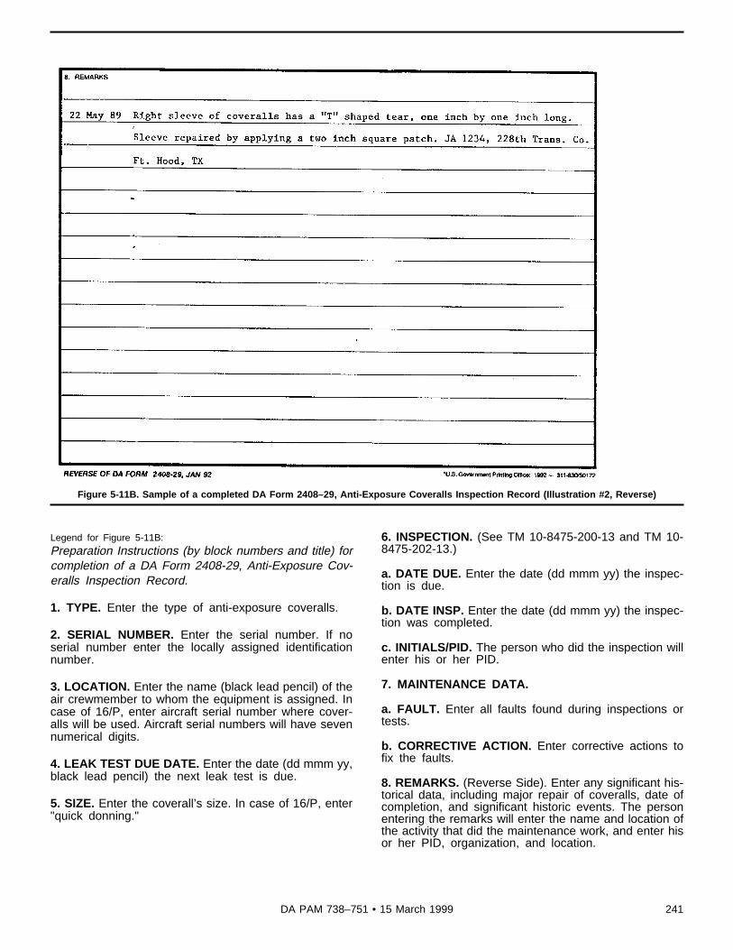
Figure 5-11B. Sample of a completed DA Form 2408–29, Anti-Exposure Coveralls Inspection Record (Illustration #2, Reverse)
Legend for Figure 5-11B:Preparation Instructions (by block numbers and title) forcompletion of a DA Form 2408-29, Anti-Exposure Cov-eralls Inspection Record.
1. TYPE. Enter the type of anti-exposure coveralls.
2. SERIAL NUMBER. Enter the serial number. If noserial number enter the locally assigned identificationnumber.
3. LOCATION. Enter the name (black lead pencil) of theair crewmember to whom the equipment is assigned. Incase of 16/P, enter aircraft serial number where cover-alls will be used. Aircraft serial numbers will have sevennumerical digits.
4. LEAK TEST DUE DATE. Enter the date (dd mmm yy,black lead pencil) the next leak test is due.
5. SIZE. Enter the coverall’s size. In case of 16/P, enter"quick donning."
6. INSPECTION. (See TM 10-8475-200-13 and TM 10-8475-202-13.)
a. DATE DUE. Enter the date (dd mmm yy) the inspec-tion is due.
b. DATE INSP. Enter the date (dd mmm yy) the inspec-tion was completed.
c. INITIALS/PID. The person who did the inspection willenter his or her PID.
7. MAINTENANCE DATA.
a. FAULT. Enter all faults found during inspections ortests.
b. CORRECTIVE ACTION. Enter corrective actions tofix the faults.
8. REMARKS. (Reverse Side). Enter any significant his-torical data, including major repair of coveralls, date ofcompletion, and significant historic events. The personentering the remarks will enter the name and location ofthe activity that did the maintenance work, and enter hisor her PID, organization, and location.
241DA PAM 738–751 • 15 March 1999

Figure 5-12A. Sample of a completed DA Form 2408–30, NVG Inspection and Maintenance Record (Illustration #1, Front)
242 DA PAM 738–751 • 15 March 1999

Figure 5-12B. Sample of a completed DA Form 2408–30, NVG Inspection and Maintenance Record (Illustration #2, Reverse)
243DA PAM 738–751 • 15 March 1999

Figure 5-12C. Sample of a completed DA Form 2408–30, NVG Inspection and Maintenance Record (Illustration #3, Front)
Legend for Figure 5-12C:Preparation Instructions (by block title) for completion ofa DA Form 2408-30, NVG Inspection and MaintenanceRecord
1. NOMENCLATURE. Enter the item name, for exam-ple, NVG.
2. MODEL. Enter the model number, for example, AN/PVS-5A.
3. SERIAL NUMBER. Enter the serial number of theitem.
4. NSN. Enter the National Stock Number of the item.
5. UIC. Enter the Unit Identification Code for the unit oractivity that maintains the item.
6. NEXT INSPECTIONS DUE. Enter the type of inspec-tions and the next date (black lead pencil) due for eachinspection. The three month PMCS due date will bechanged only if a three month PMCS is performed early,which may require a second three month PMCS to beperformed inside the scheduled six month service win-dow. The 6-month service window is closed upon com-pletion of the service and a new one is started. The use
of transparent tape is authorized and must be of thetype you can print on with a pencil.
PART I—FAULT INFORMATION
STATUS. Enter the status symbol that applies to thefault or maintenance action in the FAULT/REMARKSsection. Once a status symbol is in the STATUS block, itwill not be erased or changed even if in error (para 1-8).The person who corrects a red "dash" or red diagonalfault will enter his or her last name initial over the statussymbol. A red "X" or circled red "X" status symbol will beinitialed (blue/black ink ballpoint pen) over by a TI.
SYS. Leave blank at this time.
DATE. Enter the date (dd mmm yy) the fault was dis-covered or a remark is made.
NO. Leave blank at this time.
TIME. Enter the time of day (24-hour clock) the faultwas discovered, for example, 0930 or 1425.
PID. Leave blank at this time.
FAULT/REMARK. Enter a short description of the faultor maintenance, checks, services, or other inspections.The person who makes the entry will sign his or her
244 DA PAM 738–751 • 15 March 1999

name behind the entry. If more space is needed to entera fault/remark then enter "Continued" on the last line ofthe FAULT/REMARK section and continue in the nextopen FAULT/REMARK section.
A/C HRS. Leave blank at this time.
WHEN DISC. Leave blank at this time.
HOW REC. Leave blank at this time.
MAL EFF. Leave blank at this time.
WUC. Leave blank at this time.
W.O. Enter the work order number from the DA Form2407 or PC work request. If none, leave blank.
REQ. Enter the supply requisition number if a part isordered. If none, leave blank.
OTHER. Leave blank at this time.
PART II—CORRECTING INFORMATION.
DATE. Enter date (dd mmm yy) the fault was corrected.
TIME. Enter the time (24-hour clock) the fault was cor-rected, for example, 0930 or 1425.
HRS. Leave blank at this time.
ACTION CODE. Leave blank at this time.
WUC. Leave blank at this time.
ACTION. Enter a short description of the action taken tocorrect the fault or maintenance, checks, services, orother inspections. The person who corrects the fault orcompletes the checks, services or other inspections willsign his or her name. Examples of what can be enteredare:
a. Left tube shaded — "Tube replaced," "Replaced,""Repl tube," and so forth.
b. 120 day visor insp due 28 Oct 91 — "Compl," "Inspcompl," and soforth.
c. Distortion in left tube — "Distortion evaluation com-pleted, released for flight."
PID. Leave blank at this time.
HOURS. Leave blank at this time.
PID. Leave blank at this time.
CMH. Leave blank at this time.
OMH. Leave blank at this time.
FMH. Leave blank at this time.
DMH. Leave blank at this time.
TIPID. Use if the fault is a red "X" or circled red "X,"otherwise leave blank. The TI that verifies the corrective
action and completion of the MOC will enter his or hersignature in this block.
TI MANHOURS. Leave blank at this time.
7. NVG OPERATIONAL HOURS. (Reverse Side)
a. CURRENT. Leave blank at this time, unless theMACOM has directed the NVG usage time be tracked.
b. TODAY. Leave blank at this time, unless the MACOMhas directed the NVG usage time be tracked.
c. TOTAL. Leave blank at this time, unless the MACOMhas directed the NVG usage time be tracked.
245DA PAM 738–751 • 15 March 1999

Appendix AReferences
Section IRequired Publications
AR 12–12Processing Discrepancy Reports Against Foreign Military SalesShipments (cited in para 3–2).
AR 95–1Army Aviation Flight Regulations (cited in paras 2–3 and 3–2).
AR 95–3Aviation: General Provisions, Training, Standardization, andResource Management (cited in paras 1–12, 1–15, and 1–25).
AR 700–138Army Logistics Readiness and Sustainability (cited in para 3–11).
AR 750–1Army Material Maintenance Policy and Retail MaintenanceOperations (cited in paras 1–1, 3–11, and 4–14).
AR 750–2Army Material Maintenance Wholesale Operations (cited in paras1–1, and 3–2).
TB 1–1500–341–01Aircraft Components Requiring Maintenance Management andHistorical Data (cited in paras 1–12, 1–14, 1–17, 1–18, 1–19, 3–3,3–13, 3–20, 4–4, 4–7, 4–8, and 4–15).
TB 43–0002–3Maintenance Expenditure Limits for Army Aircraft (cited in para 3-8).
TB 43–0106Aeronautical Equipment Army Oil Analysis Program (cited in para4–14).
TM 1–1500–328–23Aeronautical Equipment Maintenance Management Policies andProcedures (cited in paras 1–9, 1–15, 1–20, 1–24, 1–25, 2–10, 2–11,3–12, 3–19, 3–20, 4–7, 4–8, and 4–15).
Section IIRelated PublicationsA related publication is merely a source of additional information.The user does not have to read it to understand this publication.
AR 25–55The Department of the Army Freedom of Information Act.
AR 310–25Dictionary of United States Army Terms.
AR 310–50Authorized Abbreviations and Brevity Codes.
AR 380–5Department of the Army Information Security Program.
AR 385–40Accident Reporting and Records.
AR 570–2Manpower Requirements Criteria.
AR 672–20Incentive Awards.
AR 700–4Logistics Assistance Program.
AR 700–139Army Warranty Program Concept and Policies.
AR 710–1Centralized Inventory Management of the Army Supply System.
AR 710–2Supply Policy Below the Wholesale Level.
AR 710–3Asset Transaction Reporting System.
AR 725–50Requisition, Receipt, and Issue System.
AR 735–5Policies and Procedures for Property Accountability.
AR 735–11–2Reporting of Item and Packaging Discrepancies.
AR 750–10Modification of Materiel and Issuing Safety-of-Use Messages andCommercial Vehicle Safety Recall Campaign Directions.
AR 750–43Army Test, Measurement, and Diagnostic Equipment Calibrationand Repair Support Program (TMDE).
DA Pam 385–40Safety: Aircraft Accident Investigation and Reporting.
DA Pam 700–126Basic Functional Structure.
DA Pam 710–2–1Using Unit Supply System, Manual Procedures.
DA Pam 738–750The Army Maintenance Management System (TAMMS).
DOD 4160.21–MDefense Reutilization and Disposal Manual.
TB 43–0001Equipment Improvement Report and Maintenance Digest.
TB 750–25Maintenance of Supplies and Equipment: Army Test, Measurementand Diagnostic Equipment (TMDE) Calibration and Repair SupportProgram.
TM 10–8415–206–12&POperator, Organizational and Direct Support Maintenance Manual(Including Repair Parts and Special Tools List) Helmet, Flying,Protective (Model SPH-4, Regular) (NSN 8415-00-144-4981) and(Model SPH-4, Extra Large) (NSN 8415-00-144-4985).
TM 10–8475–200–13Use, Inspection, Fitting and Maintenance Inspections for Anti-Exposure Assembly, Type CWU-21/P (TO 14P3.5.8).
TM 10–8475–202–13Operation, Service and Maintenance Inspections for Quick DonningAnti-Exposure Flying Coverall, Type CWU-16/P.
246 DA PAM 738–751 • 15 March 1999

TM 11–5820–640–15Operator’s, Organizational, Direct Support, General Support, andDepot Maintenance Manual: Radio Sets, AN/URC-10, AN/URC-10A and ACR RT-10.
TM 11–5820–767–12Operators and Organizational Maintenance Manual: Radio Set AN/URC-90 (NSN 5820-00-832-9158).
TM 11–5820–800–13&POperators and Organizational Maintenance Manual (IncludingRepair Parts and Special Tools List): Radio Set, AN/PRC-90 (NSN5820-00-782-5308)
TM 11–5855–263–23&PAviation Unit and Direct Support Maintenance Manual, AviationNight Vision Imaging System AN/AVS-6(V)1 and AN/AVS-6(V)2.
TM 11–5855–238–23&PUnit Maintenance Manual, Night Vision Goggles AN/PVS-5 (NSN5855-00-150-1820), AN/PVS-5B (NSN 5855-01-228-0938), AN/PVS-5C (NSN 5855-01-228-0936).
TM 38–L09–11Functional Users Manual for Maintenance Reporting andManagement (MRN).
TM 55–1500 and TM 55–1520 seriesMaintenance Inspection Checklist.
TM 55–1520–342–23Army Aviation Maintenance Engineering Manual For Weight andBalance.
TM 55–1660–247–12Operation, Fitting, Inspection and Maintenance with Illustrated PartsBreakdown for MBU-12P Pressure-Demand Oxygen Mask Part No.834-75-01 (NSN 1660-01-081-9157LS), 834-75-02 (NSN 1660-01-073-7595LS), 834-75-03 (NSN 1660-01-073-7596LS), AND 834-75-04 (NSN 1660-01-081-2366LS) (to 15X5-3-6).
TM 55–1680–317–23&PAviation Unit and Aviation Intermediate Manual with Repair Partsand Special Tools List for Army Aircraft Survival Kits.
AISM 25–L3P–AWD–ZZZ–EMULLS-Aviation End User Manual.
Section IIIPrescribed Forms
DA Form 2402Exchange Tag. (Prescribed in para 3–5.)
DA Form 2405Maintenance Request Register. (Prescribed in para 3–10.)
DA Form 2407Maintenance Request. (Prescribed in para 3–11.)
DA Form 2407–1Maintenance Request Continuation Sheet. (Prescribed in para 3–11.)
DA Form 2408Equipment Log Assembly. (Prescribed in para 2–3.)
DA Form 2408–4–1Weapon Record Data. (Prescribed in para 2–5.)
DA Form 2408–4–2Weapon Sighting Data (OH-58D). (Prescribed in Para 2–6.)
DA Form 2408–4–3Weapon Sighting Data (AH-64A). (Prescribed in Para 2–7.)
DA Form 2408–5Equipment Modification Record. (Prescribed in para 4–3 and 5–3.)
DA Form 2408–5–1Equipment Modification Record (component). (Prescribed in para4–4.)
DA Form 2408–12Army Aviator’s Flight Record. (Prescribed in para 2–8.)
DA Form 2408–13Aircraft Status Information Record. (Prescribed in para 2–9.)
DA Form 2408–13–1Aircraft Inspection and Maintenance Record. (Prescribed in para2–10.)
DA Form 2408–13–2Related Maintenance Actions Record. (Prescribed in para 2–11.)
DA Form 2408–13–3Aircraft Technical Inspection Worksheet. (Prescribed in para 3–9.)
DA Form 2408–14–1Uncorrected Fault Record (Aircraft). (Prescribed in para 2–12.)
DA Form 2408–15Historical Record for Aircraft. (Prescribed in paras 4–5 and 5–4.)
DA Form 2408–15–2Aircraft Vibration Record. (Prescribed in para 4–6.)
DA Form 2408–16Aircraft Component Historical Record. (Prescribed in para 4–7.)
DA Form 2408–16–1History Recorder, Component, Module Record. (Prescribed in para4–8.)
DA Form 2408–17Aircraft Inventory Record. (Prescribed in para 4–9.)
DA Form 2408–18Equipment Inspection List. (Prescribed in para 2–13.)
DA Form 2408–19Aircraft Engine Turbine Wheel Historical Record. (Prescribed inpara 4–10.)
DA Form 2408–19–1T53/T55 Turbine Engine Analysis Check Record. (Prescribed inpara 4–11.)
DA Form 2408–19–2T700 Series Turbine Engine Analysis Check Record. (Prescribed inpara 4–12.)
DA Form 2408–19–3Engine Component Operating Hours Record. (Prescribed in Para4–13.)
DA Form 2408–20Oil Analysis Log. (Prescribed in para 4–14.)
DA Form 2408–21Life Raft Inspection Record. (Prescribed in para 5–5.)
247DA PAM 738–751 • 15 March 1999

DA Form 2408–22Helmet and Oxygen Mask/Connector Inspection Record. (Prescribedin para 5–6.)
DA Form 2408–23Survival Radio/Emergency Location Transmitter Inspection Record.(Prescribed in para 5–7.)
DA Form 2408–24Survival Kit Inspection and Maintenance Record. (Prescribed inpara 5–8.)
DA Form 2408–25Mesh Net Survival Vest Inspection Record. (Prescribed in para5–9.)
DA Form 2408–26Life Preserver Inspection Record. (Prescribed in para 5–10.)
DA Form 2408–27Life Preserver Data. (Prescribed in para 5–11.)
DA Form 2408–28Oxygen Console Service Record. (Prescribed in para 5–12.)
DA Form 2408–29Anti-Exposure Coveralls Inspection Record. (Prescribed in para5–13.)
DA Form 2408–30NVG Inspection and Maintenance Record. (Prescribed in para5–14.)
DA Form 2408–31Aircraft Identification Card. (Prescribed in para 2–4.)
DA Form 2408–33–RMeter Tracked Component Record. (Prescribed in para 4-15.)
DA Form 2410Component Removal and Repair/Overhaul Record. (Prescribed inpara 3–13 through 3–19.)
DD Form 1574Serviceable Tag-Materiel (yellow). (Prescribed in para 3–22.)
DD Form 1574–1Serviceable Label-Materiel (yellow). (Prescribed in para 3–22.)
DD Form 1575Suspended Tag-Materiel (brown). (Prescribed in para 3–23.)
DD Form 1575–1Suspended Label-Materiel. (Prescribed in para 3–23.)
DD Form 1576Test/Modification Tag-Materiel (blue). (Prescribed in para 3–24.)
DD Form 1576–1Test/Modification Label-Materiel. (Prescribed in para 3–24.)
DD Form 1577Unserviceable (Condemned) Tag-Materiel (red). (Prescribed in para3–25.)
DD Form 1577–1Unserviceable (Condemned) Label-Materiel. (Prescribed in para3–25.)
DD Form 1577–2Unserviceable (Reparable) Tag-Materiel (green). (Prescribed in para3–26.)
DD Form 1577–3Unserviceable (Reparable) Label-Materiel. (Prescribed in para3–26.)
DD Form 2332Materiel Deficiency Report. (Prescribed in para 3–6.)
SF Form 368Product Quality Deficiency Report (Prescribed in para 3–8.)
Section IVReferenced Forms
DA Form 209Delay, Referral or Follow-Up Notice.
DA Form 1687Notice of Delegation of Authority-Receipt for Supplies.
DA Form 2028Recommended Changes to Publications and Blank Forms.
DA Form 2765–1Request for Issue or Turn-In.
DD Form 173/3Joint Message Form (OCR).
DD Form 365–3Chart C-Basic Weight and Balance Record.
DD Form 365–4Weight and Balance Clearance Form F-Transport/Tactical.
DD Form 1348–1AIssue Release/Receipt Document.
DD Form 1348–2DoD Issue Release/Receipt Document With Address Label.
DD Form 1896Jet Fuel Identaplate.
DD Form 1897AVGAS Identaplate.
SF Form 364Report of Discrepancy.
Appendix BNuclear, Biological, and Chemical Detection-Decontamination Documentation ProceduresB–1. When aircraft, aviation-associated equipment, or other aero-nautical equipment is suspected to have been contaminated withnuclear, biological, or chemical materiel the following steps will betaken to decontaminate the equipment (see table B-1).
248 DA PAM 738–751 • 15 March 1999

Table B–1Legend: Nuclear, Biological, and Chemical Detection-Decontamination Documentation Procedures
STEP A BIf Then
1 An aircraft or aeronautical equipment is suspected to have beencontaminated.
A security police team will establish a cordon around the aircraft.
2 Isolated parking is necessary. A security police team will securethe area and the organization section.
The pilot will advise the tower of the known or suspected contami-nation. The pilot will request that isolated parking be provided forthe aircraft.
3 The ground crew and maintenance personnel will not approachthe aircraft or begin servicing or maintenance until after the aircraftis completely inspected and decontaminated if necessary.
4 The detection team will perform detection per prescribed proce-dures to determine the type, amount, and location of contamina-tion.
5 The detection team supervisor will direct maintenance personnelto enter the circled Red N, B or C on the DA Form 2408-13 and2408-13-1 and describe the extent of the contamination.
6 If an aircraft component or part cannot be decontaminated, thecomponent or part will be removed and disposed of as contami-nated waste.
7 Contamination occurs with a chemical agent. A special entry will be made on the DA Form 2408-18 to show thata special detection reinspection is needed at the next three sched-uled hourly periodic, phase, or other scheduled inspections.
8 The aircraft has been decontaminated. The decontamination team chief will enter the corrective action inthe Correcting Information block of the DA Form 2408-13-1 andwill enter his or her signature following this entry. The team chiefwill then place his or her last name initial over the symbol in thestatus block of the Fault Information block on the DA Form 2408-13-1 that applies.
9 Maintenance personnel will perform corrosion control as called for,since some decontaminates are highly corrosive.
10 Maintenance personnel will make an entry on the DA Form 2408-15 to describe the type and extent of contamination. The unclassi-fied designator of the contaminant involved and the decontami-nates used will be included.
11 The local commander will establish necessary administrativeprocedures related to accomplishing decontamination of the air-craft.
Controls will be set up to assure that unauthorized personnel donot enter the isolated area until needed decontamination has beencompleted.
12 Plans will be made to establish isolated areas.13 Assurance will be provided that needed decontamination is ac-
complished and verified by qualified personnel.14 Procedures will be set up to return the aircraft to service after
decontamination has been performed.15 Plans and procedures will be made to provide maintenance guid-
ance and/or assistance to the decontamination team.
Appendix CSupply Condition CodesC–1. The supply condition codes are to describe the conditioncodes used on DA Forms, records, and DD Forms 1574, 1574-1,
1575, 1575-1, 1576, 1576-1, 1577, 1577-1, 1577-2, 1577-3 con-tained in this pamphlet (see table C-1).
Table C–1Supply Condition Codes
Code Title Explanation
A Serviceable (issuable without qualification). New, used, or repaired materiel that is serviceable and issuable toall customers without limitation or restriction. Includes materiel withmore than 6 months’ shelf life remaining.
B Serviceable (issuable without qualification) New, used, or repaired materiel that is serviceable and issuablefor its intended purpose. However, it is restricted from issue tospecific units, activities, or geographical areas because of its lim-ited usefulness or short service life expectancy. Includes materielwith 3 through 6 months’ shelf life remaining.
C Serviceable (priority issue). Items that are serviceable and issuable to selected customers, butmust be issued, when feasible, before condition A and B materielto avoid loss as a usable asset. Includes materiel with less than 3months’ shelf life remaining.
D Serviceable (test/modification). Serviceable items that require test, alteration, modification, con-version, or disassembly.
E Unserviceable (limited restoration). Items that involve only limited expense or efforts to restore to serv-iceable condition. This is done in the storage activity.
F Unserviceable (reparable). Economically reparable items that need repair, or overhaul.
249DA PAM 738–751 • 15 March 1999

Table C–1Supply Condition Codes—Continued
Code Title Explanation
G Unserviceable (incomplete). Items that need other parts or components to complete the enditem before issue.
H Unserviceable (condemned). Items that are unserviceable and do not meet repair criteria, con-tain no components or assemblies to be reclaimed, and are of novalue to the Government except for material content.
J Suspended (in stock). Items in stock that have been suspended from issue pending con-dition classification or analysis, when the true condition is notknown.
K Suspended (returns). Items returned from customers and users suspended from issuepending inspection and condition classification.
L Suspended (litigation). Items held pending litigation or negotiation with contractors com-mon carriers. Includes shipments with shortages, overages, de-fects, or other conditions that call for negotiation or litigation.
M Suspended (in work). Items on inventory control record but that have been delivered andaccepted by an Army or DOD maintenance facility or a contrac-tor’s plant for processing.
N Suspended (ammunition suitable for emergency combat use on-ly).
Ammunition stocks suspended from issue except for emergencycombat use.
P Unserviceable (reclamation). Items that are unserviceable, uneconomically reparable becauseof physical inspection, tear down, or engineering decision, itemcontains serviceable components or assemblies that may be re-claimed.
R Suspended (reclaimed items, awaiting condition determination). Assets turned in by reclamation activities that do not have the ca-pability (e.g., skills, personnel, or test equipment) to determine thematerial condition. Actual condition will be determined before in-duction into maintenance activities for repair/modification.
S Unserviceable (Scrap). Items that have no value except for its basic material content. Nostock will be recorded as on hand in condition code S. This isused only on transactions that involve shipments to DRMOs.
Appendix DDepartment of the Army list of Aircraft and AviationAssociated Equipment on which forms and recordsare to be maintainedD – 1 . T h i s a p p e n d i x p r o v i d e s a l i s t o f a v i a t i o n e q u i p m e n t a n dspecifies the DA forms on which data are to be recorded, main-tained, and/or sent through command designated data reduction cen-ters to LOGSA and AMCOM.D–2. The forms called for are identified opposite the nomenclatureof the equipment in table D-1.D–3. Aircraft and other aviation equipment are arranged by equip-ment category code (ECC). The column headings are ECC, nomen-clature, DA Forms to be maintained, and the end item code (EIC).The ECC is a two-character alpha designation that shows the gen-eral and subgrouping for the aviation equipment. The EIC is a three-character alpha and/or alpha/numerical designation that is used in anautomated data processing system. Three asterisks indicate EIC notassigned.D–4. The purpose, detailed needs, use, preparation, processing, and
disposition of the DA forms are contained in chapters 1, 2, 3, 4 and5.D–5. Commanders may direct the preparation of TAMMS-A formsnot listed for equipment for local management purposes. However,all copies of forms used will be retained within the command.D–6. DA Form 2408-5 and DA Form 2408-5-1 will be filled outonly upon receipt of a MWO or completion of a SOF message, oraviation safety action message.D–7. DA Form 2408-13-2 will be filled out only when clearingmajor faults and deficiencies listed on DA Form 2408-13-1 and DAForm 2408-13-3.D–8. DA Form 2408-13-3 is not added to this Appendix becausethis form is required for all equipment technical inspections.D–9. DA Form 2408-14-1 will be filled out when the first uncor-rected fault or deferred maintenance condition exists.D–10. DA Form 2408-20 will be filled out on an as-needed basisas directed by the publications that apply.D–11. A list of aircraft and their NSNs is provided in table E-1.
250 DA PAM 738–751 • 15 March 1999

Table D–1DA FORMS TO BE MAINTAINED (page 1)
251DA PAM 738–751 • 15 March 1999

Table D–1DA FORMS TO BE MAINTAINED (page 2)
252 DA PAM 738–751 • 15 March 1999

Table D–1DA FORMS TO BE MAINTAINED (page 3)
Table D–1DA FORMS TO BE MAINTAINED (page 4)
253DA PAM 738–751 • 15 March 1999

Table D–1DA FORMS TO BE MAINTAINED (page 5)
Appendix EList of Aircraft and their National Stock NumbersE–1. The aircraft mission, design, series (MDS), and NSN forArmy aircraft are shown in this appendix for easy reference when
filling out DA Forms and Records covered in this pamphlet (seetable E-1 below).
Table E–1List of Aircraft and their National Stock Numbers
Aircraft Stock No.
AH-1E 1520-01-192-2478AH-1F 1520-01-168-4260AH-1P 1520-01-168-4259AH-1S 1520-00-504-9112AH-64A 1520-01-106-9519AH-64D 1520-01-355-8250C-12C 1510-01-070-3661C-12D 1510-01-087-9129C-12F 1510-01-235-5840C-12L 1510-01-265-2043CH-47C 1520-00-871-7308CH-47D 1520-01-088-3669EH-1H 1520-00-368-8442EH-1X 1520-01-042-9396EH-60A 1520-01-082-0686MH-47E 1520-01-282-3747MH-60K 1520-01-282-4051OH-58A 1520-00-169-7137OH-58C 1520-01-020-4216OH-58D 1520-01-125-5476OH-6A 1520-00-918-1523RC-12D 1510-01-131-8262RC-12G 1510-01-215-2942RC-12H 1510-01-214-8354RC-12K 1510-01-235-5839RC-12P 1510-01-370-0805RU-21H 1510-00-394-3320RV-1D 1510-00-368-8440U-21A 1510-00-933-8223U-21F 1510-00-169-0295U-21G 1510-00-140-1627UH-1H 1520-00-087-7637UH-1M 1520-00-809-2631UH-1V 1520-01-043-4949UH-60A 1520-01-035-0266UH-60L 1520-01-298-4532UV-18A 1510-01-011-1462
254 DA PAM 738–751 • 15 March 1999

255DA PAM 738–751 • 15 March 1999

Glossary
Section IAbbreviations
A/CAircraft
ACEAircraft Condition Evaluation
ADPEAutomated Data Processing Equipment
ALSEAviation Life Support Equipment
AMCU.S. Army Materiel Command
AMDFArmy Master Data File
AMSSArmy Materiel Status System
AOAPArmy Oil Analysis Program
APUAuxiliary Power Unit
ARNGUSArmy National Guard of the United States
ASAMAviation Safety Action Message
AVCRADAviation Classification Repair Activity Depot
AVIMAviation Intermediate Maintenance
AVUMAviation Unit Maintenance
BDARbattle damage assessment and repair
CAGEC o n t r a c t o r a n d G o v e r n m e n t E n t i t y C o d e(Manufacturer’s Code)
CCcondition change
CCADCorpus Christi Army Depot
CDRcommander
CFcarried forward
CGcenter of gravity
CLchecklist
DADepartment of the Army
DLRdepot level reparable
DMNdocument management number
DMWRDepot Maintenance Work Requirement
DODDepartment of Defense
DODAACD e p a r t m e n t o f D e f e n s e A c t i v i t y A d d r e s sCode
DRMODefense Reutilization and Marketing Office
DSNDefense Switched Network
EAWBSE w a r d s A u t o m a t e d W e i g h t a n d B a l a n c eSystem
ECPengineering change proposal
EGTExhaust Gas Temperature
EICEnd Item Code
EIREquipment Improvement Recommendation
ELTEmergency Locator Transmitter
ETIelapsed time indicator
FAAFederal Aviation Administration
FATfree air temperature
FCCFire Control Computer
FMCFully Mission Capable
FODForeign Object Damage
FOIAFreedom of Information Act
HITHealth Indicator Test
HSFhot section factors
IAWin accordance with
ICAOInternational Civil Aviation Organization
IPSinches per second
LARLogistic Assistance Representative
LASLogbook Automated System
LCFLegitimate Code File
LIFlight interface filter
LOGSALogistics Support Activity
LRULine Replaceable Unit
MACOMMajor Army Command
MAPMilitary Assistance Program
MAOTMaximum Allowable Operating Time
MARCmanpower requirement criteria
MDSmission, design, series
MFPMateriel Fielding Plan
MIMMaintenance Information Message
MMCMateriel Management Center
MMSmast mounted sight
MOCmaintenance operational check
MRMilliradian
MRMmaintenance reporting and management
MTAmaintenance training airframe
MTFmaintenance test flight
MWOmodification work order
256 DA PAM 738–751 • 15 March 1999

NICPNational Inventory Control Point
NMCnot mission capable
NMCMnot mission capable maintenance
NMCSnot mission capable supply
NMPNational Maintenance Point
NORNotice of Revision
NRTSnot repairable this station
NSNNational Stock Number
NVGNight Vision Goggle(s)
OAToutside air temperature
ORFoperational readiness float
ORG WONorganization work order
PACpower assurance check
PCWpreviously complied with
PDpriority designator
PIDpersonnel identifier
PMCpartial mission capable
PMDpreventive maintenance daily
PMSpreventive maintenance services
PNpart number
PNVSPilot Night Vision Sensor
PPMProgressive Phase Maintenance
POMCUSprepositioning of materiel configured to unitsets
PQDRProduct Quality Deficiency Report
PSIpounds per square inch
PTITpower turbine inlet temperature
QCquality control
RCR e t i r e m e n t L i f e C o m p o n e n t ; R e p l a c e m e n tComponent
RCFrepair cycle float
RCMreliability centered maintenance
RODReport of Discrepancy
RPMrevolutions per minute
RXreparable exchange
SAMSStandard Army Maintenance System
SAILSStandard Army Intermediate Level Supply
SAMISSupply Accounting and Management Infor-mation System
SARSSStandard Army Retail Supply System
SFDLRStock Funded Depot Level Reparable
SMRsource, maintenance, and recoverability
SOFsafety-of-flight
SOUsafety-of-use
SSASupply Support Activity
SSANSocial Security Account Number
STAMISS t a n d a r d A r m y M a n a g e m e n t I n f o r m a t i o nSystem
TADSTarget Acquisition Designation Sight
TBTechnical Bulletin
TBOtime between overhaul
TCtime change
TEACTurbine Engine Analysis Check
TGTturbine gas temperature
TItechnical inspector
TIPIDTechnical Inspector Personnel Identifier
TMDEtest, measurement, and diagnostic equipment
TMTechnical Manual
TRADOCU.S. Army Training and Doctrine Command
TSNtime since new
TSOtime since overhaul
TTVTarget Torque Value
TWXTeletype (message)
UICUnit Identification Code
ULLS-AUnit Level Logistics System-Aviation
WBweight and balance
WNRCWashington National Records Center
WOLFWork Order Logistics File
WONwork order number
WUCWork Unit Code
Section IITerms
Army aviation flight activityAn Army National Guard TDA activity thatprovides AVUM level functions in support ofArmy National Guard aviation assets.
Army aviation operating facilityAn Army National Guard TDA activity thatprovides AVUM level functions.
257DA PAM 738–751 • 15 March 1999
Army aviation support facilityAn Army National Guard TDA maintenanceactivity that provides AVIM and AVCRADauthorized AVIM level functions to supportArmy National Guard aviation assets.
Army Oil Analysis ProgramPart of a DOD-wide effort to detect impend-ing equipment component failures and deter-mine lubricant condition through on-line andlaboratory evaluation of used oil samples.
Army Oil Analysis Program FeedbackMaintenance and disassembly inspection dataregarding a oil sample from an engine orother major component or assembly furnishedby the operating and maintenance activitiesto the Army Oil Analysis Program.
AssemblyA combination of components or modules,and parts used as a portion of, and intendedfor installation in an aircraft or associatede q u i p m e n t e n d i t e m ; f o r e x a m p l e , e n g i n e ,transmission, and rotor head.
Aviation classification and repair activitydepotAn Army National Guard TDA maintenanceactivity that provides AVIM and authorizeddepot level functions.
Aviation-associated equipmentA v i a t i o n - a s s o c i a t e d e q u i p m e n t o r " a v i a t i o nequipment" or “equipment” are used frequ-ently in this pamphlet and other maintenancet e c h n i c a l m a n u a l s f o r e a s e o f w r i t i n g a n dr e a d i n g p r e s c r i b e d p r o c e d u r e s a n d i n s t r u c -tions. In most instances the term will be con-strued to mean related mission equipment,such as, armament systems, electronic andother equipment, night vision goggles, air-craft training devices, simulators and aviationl i f e s u p p o r t e q u i p m e n t m a n a g e d b y A M -COM. The term will also refer to uninstalledassemblies, subassemblies, and components/modules that are being processed within in-t e r m e d i a t e o r d e p o t s u p p o r t m a i n t e n a n c eshops/activities.
Aviation life support equipmentThe equipment used in case of flight opera-tion emergencies to lend support to make itpossible for aircrew members and passengersof Army aircraft to endure and to completeassigned mission. ALSE is used in case of in-flight and other crises to aid and support oc-cupants of aircraft in survival. It is used toprovide ways of safe and sure escape, de-scent, and recovery during life threateningsituations.
CalibrationThe comparison of an instrument (measure-ment standard or item of test, measurement,and diagnostic equipment) of unverified ac-c u r a c y w i t h a n i n s t r u m e n t o f k n o w n a n dgreater accuracy to detect and correct anydiscrepancy in the accuracy of the unverifiedinstrument.
CommanderA person of the armed forces with vestedauthority to direct, coordinate, and controlmilitary forces of a unit/aviation maintenanceactivity. The commander will—
a. Be held accountable for the safety of allpersonnel under his/her control and the statusof aircraft and equipment.</title>
b. Emphasize the importance of mainte-nance and ensure that subordinates are helda c c o u n t a b l e f o r t h e c o n d u c t o f a v i a t i o nequipment maintenance operations.
c . P r o v i d e l e a d e r s h i p , t e c h n i c a l s u p e r v i -s i o n , a n d m a n a g e m e n t c o n t r o l o f a v i a t i o nequipment maintenance program.
d. Emphasize the conduct and supervisionof preventive maintenance checks and serv-ices performed at the unit level; preventivemaintenance and repair at intermediate level;and repair, overhaul, or rebuild maintenanceat depot level.
e. Establish, maintain, and conduct train-ing of leaders in the maintenance organiza-t i o n t o p r o p e r l y s u p e r v i s e m a i n t e n a n c eoperations and to motivate subordinates toproperly and safely use and maintain aviationequipment.
f. Recommend improvements of the Armyaviation maintenance system.
g . E n s u r e t h a t t h e s u b m i s s i o n o f d e f i -ciency reports is prepared and submitted perchapter 3 of this pamphlet.
h. Establish an aggressive awards programf o r a i r c r e w m e m b e r s a n d a v i a t i o n m a i n t e -nance/quality control personnel.
Component/ModuleA combination of parts mounted together inmanufacture that may be tested, repaired, orreplaced as a unit; for example, starter, gen-erator, fuel pump, line replaceable unit, prin-t e d c i r c u i t b o a r d . T h e t e r m “ m o d u l e ” i sn o r m a l l y a s s o c i a t e d w i t h e l e c t r o n i c e q u i p -ment or major components of T700 series gasturbine engines.
Component OverhaulDepot level maintenance performed to restorea TC item, with a TBO assigned, to a serv-iceable condition, as prescribed in the appro-priate Depot Maintenance Work Requirement(DMWR). The item is subjected to a com-plete disassembly and inspection. All defec-tive or excessively worn parts are replacedwith new or reconditioned items. This actionw i l l " z e r o " t i m e s i n c e o v e r h a u l , b u t t i m esince new will not change.
Component RebuildDepot or contractor maintenance performedto restore an item to a like new condition inappearance, performance, and life expectan-cy. This is done by complete disassembly,inspection, and replacing all worn and unser-viceable elements with new parts or parts thathave been reworked to original manufactur-ing specifications. When an item is rebuilt itstarts a new life cycle. This action will "zero"
t i m e s i n c e n e w , t i m e s i n c e o v e r h a u l , a n dnumber of previous overhauls.
Component RepairMaintenance performed to restore a TC, RC,or CC item to serviceable condition by cor-r e c t i n g a s p e c i f i c f a i l u r e o r u n s e r v i c e a b l econdition. This allows a TC or RC item tocomplete its TBO/MAOT cycle. These ac-tions will not "zero" time since new or timesince overhaul.
Condition Change (CC) ItemAn item that is changed or repaired on an "asneeded" basis. This item does not have aTBO assigned, therefore it is not overhauled.
Contractor and Government Entity CodeCAGE code(s) are assigned to manufacturers/nonmanufacturers organizational entities/con-tractors. The primary use of the CAGE codeis in machine accounting operations relatedt o s u p p o r t m a n a g e m e n t p r o g r a m s , s u c h a scataloging and standardization. The CAGEcode is used in conjunction with the firm’sreference number relating the firm with theitem of supply, production, or design in cata-loging and other supply records, as well ason engineering documentation. These codesare essential to contract/purchase agreementsa n d v a r i o u s a c t i v i t i e s / a g e n c i e s a u t o m a t e ddata processing systems. The CAGE codes,reference number (P/N), and serial numbersare used to screen item identifications againsteach other primarily to detect duplication.
Contract maintenanceA n y m a t e r i e l m a i n t e n a n c e o p e r a t i o n p e r -formed under contract by commercial organi-zations (including the original manufacturersof the materiel). (See DOD 4151.16.)
Controlled exchangeRemoval of serviceable parts, components/modules and assemblies from unserviceablebut economically reparable aircraft or compo-n e n t s / m o d u l e s , a n d t h e i r i m m e d i a t e o rp l a n n e d r e u s e i n r e s t o r i n g a l i k e i t e m o fequipment to a mission capable condition.
Critical CharacteristicAny feature throughout the life cycle of aFSCAP, such as dimension, tolerance, finish,material or assembly, manufacturing or in-s p e c t i o n p r o c e s s , o p e r a t i o n , f i e l d m a i n t e -nance or depot overhaul requirement which ifnonconforming, missing, or degraded couldcause the failure or malfunction of a FSCAP.
Deferred MaintenanceA u t h o r i z e d d e l a y o f m a i n t e n a n c e / r e p a i r o funcorrected faults. The commander or com-mander’s designated representative must au-thorize the delay in correcting the fault.
a. Required maintenance/repair can be de-ferred only when the fault will not affect the
258 DA PAM 738–751 • 15 March 1999

safe operation of the aircraft, or the safety ofthe pilot and crew.
b. Repair on Red "X" status symbol defi-ciencies will not be deferred.
c. A status symbol circled Red "X" defi-ciency repair may be deferred, but for a lim-i t e d t i m e o n l y . O n l y t h e c o m m a n d e r , t h emaintenance officer, or higher authority cana u t h o r i z e d e l a y o f m a i n t e n a n c e o n c i r c l e dRed "X" deficiencies.
d . C o r r e c t i o n s w i t h t h e r e q u i r e d p a r t sa v a i l a b l e w i l l n o t n o r m a l l y b e d e f e r r e d .When there are minor corrections for faultsthat are labor intensive, the repair may bedeferred until the next scheduled maintenanceinspection.
DeficiencyA fault, defect, or problem so severe that itcauses an item, system, or subsystem to beinoperative or inaccurate.
Deficiency reportsThe prescribed means for users of Army air-c r a f t a n d a s s o c i a t e d e q u i p m e n t t o r e p o r tfaults, failures, and problems in design, oper-ation, maintenance, manufacture, and over-haul or rebuild of aviation end items andcomponents. Deficiency reports are submittedaccording to instructions in chapter 3.
Deficiency report exhibitThe item reported as being deficient, or asample item that represents the reported defi-cient condition, that can be torn down andanalyzed to determine the possible cause ofthe defect.
Department of Defense Activity AddressCodeThe DODAAC is a six-digit code that gives adelivery address for supplies and equipment.
Depot Maintenance Work RequirementsA maintenance serviceability standard for de-p o t m a i n t e n a n c e o p e r a t i o n s . T h e s t a n d a r dprescribes the following and other essentialfactors to ensure that an acceptable and cost-effective product is obtained:
a. Scope of work to be performed on anitem by depot level maintenance facilities,organic or contract support.
b. Types and kinds of materiel to be used.c. Quality of workmanship.d . R e p a i r m e t h o d s , p r o c e d u r e s , a n d
techniques.e. Modification requirements.f. Fits and tolerances.g. Equipment performance parameters to
be achieved.h. Quality assurance discipline.
Designated representativeSomeone authorized to sign for and/or repre-sent the commander or the person in equalm a n a g e m e n t p o s i t i o n s i n c o n t r a c t s u p p o r tmaintenance activities. This pamphlet some-t i m e s a s k s f o r t h e s i g n a t u r e o f t h e c o m -m a n d e r o r t h e c o m m a n d e r ’ s d e s i g n a t e dr e p r e s e n t a t i v e . T h e c o m m a n d e r w i l l u s e a
Memorandum (letter), orders, or DA Form1687 to appoint designated representatives.
a. The commander holds full responsibil-ity for the safety of personnel and the statusof aircraft and equipment. Designated repre-sentatives should be knowledgeable, experi-enced, and readily available to the peopleneeding their signatures and help; therefore,they must be picked carefully.
b. Changing a status symbol Red "X" to acircled Red "X" or Red "-" for limited opera-tions may be dangerous. As such, the com-m a n d e r s h o u l d l i m i t t h e n u m b e r o fd e s i g n a t e d r e p r e s e n t a t i v e s t o a m i n i m u m ,consistent with unit mission needs.
c. Due to the operational safety considera-tions, the Commander should limit the num-ber of designated representatives authorizedto change Red "X" status symbols, for one-time evacuation missions, to include only aqualified maintenance officer and/or qualifiedtest pilots.
Document Management NumberThe NMP control number assigned to theCategory I or Category II PQDR for account-ability and status reporting.
Electromagnetic environmental effect (E3)A n y f a i l u r e ( o r s e r i o u s e f f e c t ) a p p a r e n t l yc a u s e d b y , o r r e l a t e d t o , r a d i o w a v e s ,electromagnetism, voltage or current pulses( s t a t i c d i s c h a r g e , l i g h t n i n g , e l e c t r o m a g n e t i cpulse, or transient electricity), from whateversource. Example: A malfunction of any elec-tronic/electrical equipment or system that oc-c u r s a f t e r e x p o s u r e t o e l e c t r o m a g n e t i cenergy. The effect may be transitory or per-m a n e n t . S o u r c e s o f e n e r g y m a y b e r a d i ot r a n s m i s s i o n s , r a d a r , h i g h p o w e r e l e c t r i c a lg e n e r a t o r t r a n s m i s s i o n e q u i p m e n t , m o t o r s ,generators, electromagnets, static electricity,lightning, magnetic storm, or hostile radio-electronic combat. Effects observed may takethe form of a distorted display, intermittant/inappropriate indication of warning noise, in-terference, break lock or sync, uncommandedcontrol actions, system failure, burnout, ordetonation.
Equipment category codeA two-positioned alphabetical code. The firstl e t t e r i d e n t i f i e s t h e p r i m a r y c a t e g o r y o fequipment: A = Aircraft, B = Air DefenseSystems, F = Tanks, G = Combat Vehicles,and H = Tactical Vehicles, etc. The secondletter identifies a specific type of equipmentwithin the primary category, AF = Aircraft;Fixed wing, AR = Aircraft; Rotary wing, GA= Self-propelled Howitzers, HB = Truck 1/4ton, etc. The two-position ECC is used inautomated data processing systems to pro-duce the complete description of an item ofe q u i p m e n t b y m a k e , m o d e l , n o m e n c l a t u r e ,line number, and NSN if desired or needed.It is also entered in specified blocks or posi-tions on manually filled forms and records.
Flight Safety Critical Aircraft PartsAny aircraft part, assembly, or installation
c o n t a i n i n g a C r i t i c a l C h a r a c t e r i s t i c w h o s efailure, malfunction, or absence could cause acatastrophic failure resulting in loss or seri-ous damage to the aircraft or an uncomman-ded engine shutdown resulting in an unsafecondition.
FaultA term used to indicate that a piece of equip-ment has a deficiency or shortcoming.
FlightFlight starts when an airplane begins to moveforward on the takeoff roll or when a heli-copter lifts off the ground. The flight endswhen the aircraft has landed and the enginesare stopped or the flying crew changes.
Fully mission capableAircraft is fully mission capable when it canp e r f o r m a l l i t s u n i t s a s s i g n e d c o m b a tmissions.
a . F M C a i r c r a f t m u s t b e c o m p l e t e a n dfully operable with no Red "X" symbol onDA Form 2408-13 or other related forms.
b. The terms ready or available and fullymission capable refer to the same status: Air-craft is on hand and able to perform its com-bat missions.
General purpose TMDETMDE that is used or has the potential ofbeing used without significant modificationsf o r t e s t , m e a s u r e m e n t , a n d d i a g n o s i s o f arange of parameters for two or more items ofequipment or systems.
Ground support equipmentI n c l u d e s a l l A M C O M m a n a g e d a i r c r a f tground support equipment needed to maintaina i r c r a f t a n d a v i a t i o n a s s o c i a t e d e q u i p m e n t .Aviation ground support equipment mainte-nance will be documented per DA Pamphlet738-750.
Initial failureFailure upon initial use or test caused byother than accident, misuse, improper instal-l a t i o n , i m p r o p e r o p e r a t i o n , u n a u t h o r i z e drepair, or unauthorized alteration.
Installation critical characteristicsCritical characteristics that are not introducedduring the manufacture of a part but are criti-c a l f o r a s s e m b l y / i n s t a l l a t i o n ; f o r e x a m p l e , .proper torque.
Logistic Assistance RepresentativeAn individual assigned by AMC and AM-COM to advise, train and provide logistica s s i s t a n c e o n a i r c r a f t a n d o t h e r a v i a t i o nequipment.
MaintenanceThe function of keeping aircraft, components/m o d u l e s , a s s e m b l i e s , s u b a s s e m b l i e s , a n drepair parts and other aviation equipment inan operational status; restoring the material toa s e r v i c e a b l e c o n d i t i o n ; o r u p d a t i n g a n dupgrading its functional utility through modi-fication and product improvement. Common
259DA PAM 738–751 • 15 March 1999
maintenance functions are inspect, test, serv-ice, adjust, calibrate, install, remove, replace,r e p a i r , m o d e r n i z e , m o d i f y , o v e r h a u l a n drebuild.
Major faultA major fault is any fault, deficiency, or con-dition that makes an aircraft unsafe to fly orr e q u i r e s a d d i t i o n a l r e l a t e d m a i n t e n a n c e a c -t i o n s t o c l e a r t h e f a u l t , d e f i c i e n c y , o rcondition.
Manufacturing critical characteristicsCritical characteristics produced during themanufacturing process.
Materiel conditionThe state that determines the ability of anitem to accomplish its intended function.
Mission dayA mission day is defined as a 24-hour periodstarting at aircraft takeoff of the first mission.The 24-hour mission day may be extended ifnecessary to complete the mission, however,planned overflights of the 24-hour missionday are not encouraged and should be mini-mized. Aircraft under the PMD inspectionsystem will additionally comply with the fol-lowing instructions: When aircraft flight op-erations (one or more) are performed, and ad a i l y i n s p e c t i o n ( P M D ) i s c o m p l e t e d , t h eterm Mission Day is defined as any 24-hourperiod beginning at the time of aircraft take-off, first flight after completion of the lastdaily inspection. Note: Should the aircraft beairborne at the end of the 24-hour period,after landing a daily inspection is due beforenext flight.
a . E x a m p l e 1 : T h e d a i l y i n s p e c t i o n i scompleted at 1900 hours, 12 Mar 1991, takeoff is 2100 hours for 6 hours of night flightt r a i n i n g . T h e a i r c r a f t t h e n l a n d s a t 2 4 0 0hours to refuel, takes off again at 0100 hours,and flies until 0400 hours. The aircraft is notscheduled to fly until 2200 hours, 13 Mar1991. This is a Mission Day, and a dailyinspection is needed before next flight.
b . E x a m p l e 2 : T h e d a i l y i n s p e c t i o n i scompleted at 1500 hours, 16 Mar 1991, take-off is 1000 hours, 17 Mar 1991 for 8 hoursof combat support. The aircraft lands every 2hours to refuel, etc., and is scheduled to flyuntil 1900 hours. The aircraft lands to refuel,e t c . , a t 0 9 0 0 h o u r s , 1 8 M a r 1 9 9 1 a n d i sscheduled to resume combat support flight.This is a Mission Day, and a daily inspectionis needed before next flight.
Mission related equipmentEquipment installed in or on an aircraft toaccomplish one or more types of missions,for example, a 30mm cannon, the electronictarget acquisition designation sight (TADS),and the pilot night vision sensor (PNVS) in-stalled on a AH-64A helicopter to performcombat gunnery missions.
National Maintenance PointAn activity established by AMCOM (materiel
developer) to facilitate the maintenance func-tion for aircraft and associated equipment.
Not mission capableAircraft that are not flyable because of sched-uled or unscheduled maintenance, outstand-i n g e m e r g e n c y M W O / T B a n d e m e r g e n c ySOF messages, or lack of repair parts. Avia-tion associated equipment that is not opera-tional because of scheduled or unscheduledmaintenance, outstanding emergency MWO/TB and emergency SOF, one-time inspectionSOU message, or lack of repair parts. Referto AR 700-138 to determine readiness statusof equipment.
Not Mission Capable MaintenanceA i r c r a f t a n d a v i a t i o n a s s o c i a t e d e q u i p m e n th a v i n g s c h e d u l e d o r u n s c h e d u l e d m a i n t e -nance performed, complying with outstand-ing emergency MWO/TBs, emergency SOFmessages, or one-time inspection SOU mes-sage applied or complied with. Refer to AR7 0 0 - 1 3 8 t o d e t e r m i n e r e a d i n e s s s t a t u s o fequipment.
Not Mission Capable SupplyA i r c r a f t a n d a v i a t i o n a s s o c i a t e d e q u i p m e n tthat are not flyable or operable because thereare no repair parts for needed repair. Refer toAR 700-138 to determine readiness status ofequipment.
Pacing ItemsThese are major weapons or equipment sys-tems of such importance that they are subjectto continuous monitoring and management atall levels of command. Pacing items are iden-tified in the Units TO&E. Pacing items arenoted on DA Form 2407.
Personnel identifier (PID)A six digit code that gives the identificationof each person that operates, maintains, andstores aircraft and aviation associated equip-ment. The code is made up of first and lastname initials, plus the last four digits of thepersons social security account number.
Product quality deficiency reportsThe prescribed means for users of Army air-craft and associated equipment to record andsend product quality deficiency data. Productquality deficiency is a nonconforming condi-tion that limits or prevents the product fromfulfilling its purpose. This includes defects indesign, specification, material, manufacture,overhaul, rebuild, and workmanship.
Project manager/supervisorA person in charge of a civilian work forcewith vested authority to direct, coordinate,and control the work force of an aviationc o n t r a c t s u p p o r t m a i n t e n a n c e u n i t / a c t i v i t y .The project manager/supervisor will—
a. Emphasize the importance of mainte-nance and ensure that subordinates are held
a c c o u n t a b l e f o r t h e c o n d u c t o f a v i a t i o nequipment maintenance operations.
b . P r o v i d e l e a d e r s h i p , t e c h n i c a l s u p e r v i -s i o n , a n d m a n a g e m e n t c o n t r o l o f a v i a t i o nequipment maintenance program.
c. Emphasize the conduct and supervisionof preventive maintenance checks and serv-ices performed at the unit level; preventivemaintenance and repair at intermediate level;and repair, overhaul, or rebuild maintenanceat depot level.
d. Establish, maintain, and conduct train-ing of leaders in the maintenance organiza-t i o n t o p r o p e r l y s u p e r v i s e m a i n t e n a n c eoperations and to motivate subordinates toproperly and safely use and maintain aviationequipment.
e. Recommend improvements of the Armyaviation maintenance system.
f. Ensure that the submission of deficiencyreports are prepared and submitted per chap-ter 3 of this pamphlet.
Related maintenance actionsAdditional related maintenance actions/worknecessary and accomplished while clearingmajor faults/deficiencies, and conditions writ-ten up on DA Form 2408-13-1 or DA Form2408-13-3.
Remark(s)To say or write briefly a comment, observa-tion or expression of something noticed orworth mentioning.
Reportable componentA component or repair part that is classifiedas a TC (TBO), RC (MAOT), or selected CCitems that have been selected by AMCOMf o r a c c u m u l a t i o n a n d r e p o r t i n g o f m a i n t e -nance data on the DA Form 2410. Reportablecomponents/modules are listed in TB 1-1500-341-01 or for ULLS-A units in the compo-nent LCF.
Retirement Change (RC) ItemAn item that has been assigned a safe maxi-m u m a l l o w a b l e o p e r a t i n g t i m e s i n c e n e w ,that the item can safely be operated before itm u s t b e r e m o v e d f r o m s e r v i c e , m u t i l a t e d ,and lost to the Army inventory. This item canbe repaired prior to reaching it’s MAOT, nor-mally RC items will not be overhauled, andmust be removed from service when theyreach their MAOT.
Stock funded depot level reparableAn item with a maintenance repair code of Dor L or an automatic return item code of C,E, R, or S.
Technical inspectionA visual, touch and feel inspection made by atechnically qualified person (normally a qual-ity control technical inspector). These inspec-tions are performed on aircraft and aviationassociated equipment per maintenance per-formance standards established in the techni-c a l m a n u a l s t h a t a p p l y t o t h e e q u i p m e n t .Technical inspections will also be done onaviation equipment forms, records, and files,
260 DA PAM 738–751 • 15 March 1999
maintenance operations and supply facilities,and general housekeeping at all flight lineareas. The results of the technical inspectionswill be used to:
a . A s s u r e t h a t q u a l i t y m a i n t e n a n c e i sperformed.
b. Determine serviceability.c. Determine the economical reparability
of the equipment.d. Estimate cost of damage resulting from
incidents/accidents.e . D e t e r m i n e h o w m a n y m a n h o u r s a n d
repair parts are needed to restore equipmentto a serviceable condition.
f . D e t e r m i n e c a u s e o f t h e u n s e r v i c e a b l econdition of the equipment.
Time Between Overhaul (TBO)The established maximum allowable operat-ing time (MAOT) since new or overhaul, thatan item can be operated before it must beremoved from service and returned to a depotlevel facility for overhaul. Time since newwill not be changed, time since overhaul willbe "zeroed" and number of previous over-h a u l s w i l l b e i n c r e a s e d b y o n e a f t e r a noverhaul.
Time Change (TC) ItemAn item that has a fixed operating time be-tween overhauls based of safety or designlimitations. The item must be replaced with anew or fully serviceable item after the speci-fied time. The item will then be overhauledat a depot level facility.
Total Cumulative counts and hoursT h e t o t a l c u m u l a t i v e L C F - 1 , L C F - 2 , T / T Iand operating hours that a T-700 series en-gine, module, component, or subcomponenthas accumulated since new regardless of his-t o r y r e c o r d e r c h a n g e s . U n i t i d e n t i f i c a t i o ncode A six-character code assigned to a spe-cific unit.a. When this pamphlet asks for aUIC, all units, organizations, and activitieswill use their own UIC.b. Contractors, manu-facturers, and commercial activities do nothave UICs. They will use the Contractor andGovernment Entity (CAGE) when a UIC iscalled for. Put the letter "K" in front of theCAGE. For example, Bell Helicopter, CAGE97499, will be turned into a contractor UIC,K97499.
Weapons/Equipment System DesignatorCodeA two-character code that is given to equip-ment for supply use. The code is put on theDA Form 2407 and supply requests. You willfind these codes in AR 725-50 and DA Pam710-2-1.
Work dayThe normal duty shift set by the local com-mand. For the purposes of this pamphlet, anormal duty shift will not exceed a 12-hourperiod.
Work Unit CodeThe Work Unit Code (WUC) is a coding
structure developed for Army aircraft compo-nents/modules to show the relationship of as i n g l e c o m p o n e n t t o a m a j o r c o m p o n e n t /module. Work Unit Codes are established toidentify functional grouping, major sections,systems installations or major components/m o d u l e s , s p e c i f i c m a j o r c o m p o n e n t s / m o d -u l e s , a n d s u b c o m p o n e n t s o f t h e a i r c r a f t .These codes are listed in TB 1-1500-341-01(Aircraft Components Requiring MaintenanceManagement and Historical Data Reports).
261DA PAM 738–751 • 15 March 1999

IndexThis index contains no entries.
262 DA PAM 738–751 • 15 March 1999

0(7(5 75$&.(' &20321(17 5(&25'
)RU XVH RI WKLV IRUP� VHH '$ 3$0 �������� WKH SURSRQHQW DJHQF\ LV '&6/2*
120(1
5(09 +56
'$ )250 ��������5� 2&7 ��
3DJH RI
�� 120(1&/$785( �� 161 �� 3$57 180%(5 25
02'(/
�� 6(5,$/ 180%(5 �� :8&
�� $&)7 02'(/ �� $&)7 6(5,$/ 180%(5 �� 0(7(5 5($',1*6 $7 ,167�� $&)76 +56
,167$//('
120(1&/$785(
$1'
:8&
3�1
$1'
161
&20321(17
6(5,$/ 180%(5 25
/2&$7,21
5(3/$&(�
0(17 '8(
0(7(5
5($',1*
5(3/$&(
/,)(
120(1
,167 +56
&203
,167 +56
���
D E F
G
KJH L
&203
509/ +56
I
86$3$ 9����

264 DA PAM 738–751 • 15 March 1999 • R-Forms

120(1&/$785(
$1'
:8&
5(9(56( 2) '$ )250 ��������5� 2&7 ��
3�1
$1'
161
&20321(17
6(5,$/ 180%(5 25
/2&$7,21
5(3/$&(�
0(17 '8(
0(7(5
5($',1*
5(3/$&(
/,)(
120(1
,167 +56
&203
,167 +56
���
D E F
G
KJH L
120(1
5(09 +56
&203
509/ +56
I
��� 6,*1,),&$17 +,6725,&$/ '$7$
86$3$ 9����
266 DA PAM 738–751 • 15 March 1999 • R-Forms

UNCLASSIFIED PIN 057282–000

USAPAELECTRONIC PUBLISHING SYSTEMTEXT FORMATTER ... Version 2.59
PIN: 057282–000DATE: 04-09-99TIME: 14:34:34PAGES SET: 271
DATA FILE: p738x751.filDOCUMENT: DA PAM 738–751DOC STATUS: NEW PUBLICATION