
D6500 Security Receiver Operation and Installation...
56
74-04651-000-E 11/22/97 D6500 Security Receiver Operation and Installation Manual
Transcript of D6500 Security Receiver Operation and Installation...

74-04651-000-E 11/22/97
D6500 Security ReceiverOperation and Installation Manual

This page intentionally left blank.

D6500 Operation and Installation Manual74-04651-000-E 11/22/97 Page 1 1987-1997 Radionics, Inc.
Table of Contents
NOTICE .......................................................................3
1. INTRODUCTION...................................................3
2. EMERGENCY PROCEDURES ...........................4
BEFORE CALLING RADIONICS TECHNICAL SUPPORT:.4
3. SPECIFICATIONS.................................................5
DIMENSIONS........................................................5CABINET FINISH..................................................5POWER INPUT .....................................................5RINGER EQUIVALENCE .....................................5DISPLAY ................................................................5CURRENT REQUIRED (Milliamperes)................5STAND-BY POWER...............................................5TELEPHONE CONNECTIONS.............................5FCC REGISTRATION ...........................................5NOTICE: ................................................................5LISTEN-IN .............................................................5CLOCK/CALENDAR .............................................5INTERNAL PRINTER ............................................5OUTPUTS ..............................................................5LISTINGS AND APPROVALS ...............................5
4. CARD FUNCTIONS AND COMPONENTLOCATIONS................................................................6
5. DIGITAL PHONE LINE CARDS ........................8
5.1 DESCRIPTION .......................................................8Digital Phone Line Card (D6540 or D6541) ........8Line Terminator Card (D6545) .............................9
5.2 CARD INSTALLATION...........................................9Installing Phone Line Terminator Cards...............9
INSTALLING PHONE LINE CARDS..............................10
6. MAIN PROCESSING UNIT (MPU) CARDS....11
6.1 DESCRIPTION .....................................................11MPU Card (D6510 or D6511).............................11MPU Terminator Card (D6515)..........................12
6.2 CARD REMOVAL AND REPLACEMENT................12Removing the MPU Card.....................................12Replacing the MPU Card ....................................13
7. POWER SUPPLY CARDS ..................................14
7.1 DESCRIPTION .....................................................14Power Supply Card (D6530) ...............................14Power Supply Terminator Card (D6535) ............15
7.2 CARD REMOVAL AND REPLACEMENT................15Removing the Power Supply Terminator Card....15Replacing the Power Supply Terminator Card ...16Removing the Power Supply Card .......................16Replacing the Power Supply Card.......................16
8. PRINTER SPECIFICATIONS........................... 18
8.1 DESCRIPTION..................................................... 19Printer Module (D6550) ..................................... 19
8.2 MODULE REMOVAL AND REPLACEMENT.......... 19Removing the Printer Module ............................. 19Replacing the Printer Module ............................. 19Printer Terminator Card (D6555) ...................... 20
8.3 CARD INSTALLATION ........................................ 20Installing the Printer Terminator Card............... 20
8.4 CHANGING THE INTERNAL PRINTER PAPER ...... 21Changing the Paper ............................................ 21Troubleshooting .................................................. 22
8.5 EXTERNAL PRINTERS SUPPORTED..................... 22Epson LQ510/LX810 with serial option #8143... 22Okidata ML172/ML182T Serial .......................... 22Okidata ML320 Serial......................................... 23
8.6 EXTERNAL PRINTER REPORTS........................... 23
9. INSTALLATION ................................................. 24
9.1 UL INSTALLATIONS .......................................... 249.2 BURGLAR ALARM APPLICATIONS ..................... 249.3 FIRE ALARM APPLICATIONS ............................. 249.4 INSTALLATION CHECK LIST .............................. 249.5 RACK MOUNT INSTRUCTIONS ........................... 269.6 POWERING DOWN THE RECEIVER ..................... 27
10. STANDBY POWER........................................... 28
10.1 BATTERY DESCRIPTION AND SPECIFICATIONS 2810.2 REPLACING THE D126 BATTERIES.................. 2810.3 CONNECTION TO AN EXTERNAL DC POWER
SOURCE.................................................................... 28
11. CLOCK AND CALENDAR CONTROLS ...... 30
Setting the Time and Date on the D6500 ............ 30
12. PROGRAMMING THE D6500 RECEIVER.. 31
12.1 LOADING CUSTOMIZED PROGRAMS INTO THE
RECEIVER................................................................. 3112.2 EDITING PROGRAMS........................................ 31
13. PROGRAM DEFAULT INITIALIZATIONROUTINE .................................................................. 32
14. D6500 OPERATION.......................................... 33
14.1 HOW MESSAGES ARE TRANSMITTED .............. 3314.2 HOW MESSAGES ARE RECEIVED ..................... 34

D6500 Operation and Installation Manual74-04651-000-E 11/22/97 Page 2 1987-1997 Radionics, Inc.
15. D6500 STANDARD 40-CHARACTERREPORTING FORMAT.......................................... 35
15.1 INTERPRETATION OF REPORTS ........................ 35Single and Double Line Formats ........................ 35Single Line Format.............................................. 36Double Line Format............................................ 36Line 2: ................................................................. 3615.2 Message Examples ..................................... 36Status reports print as follows (not used forPulse): ................................................................. 36BFSK Example:................................................... 36Modem II Single Line Example:.......................... 36Modem II Double Line Example:........................ 36Signals transmitted during an AC Failure at theprotected premises print as follows (not used forPulse): ................................................................. 37BFSK Example:................................................... 37Modem II Single Line Example:.......................... 37Modem II Double Line Example:........................ 37Force Arming reports print as follows: .............. 37BFSK Example:................................................... 37Modem II Single Line Example:.......................... 37Pulse (4x2) Example: .......................................... 37Modem II Double Line Example:........................ 37
15.3 LCD STATUS LINE FORMAT ........................... 38System Mode (1 thru 5) ....................................... 38System Messages (7 thru 24)............................... 38Scrolling System Messages: ................................ 38Programmer System Messages: .......................... 38Buffer Usage (26 thru 34) ................................... 38Listen-In (36 thru 40) .......................................... 38
16. RECEIVING SIGNALS AT THE D6500 ........ 39
16.1 OPERATION IN MANUAL MODE ...................... 39Receiving Signals ................................................ 39Typical Alarm Receiving Sequence in ManualMode.................................................................... 39
16.2 OPERATION IN AUTOMATIC MODE ................. 39Typical Alarm Receiving Sequence in AutomaticMode.................................................................... 40
17. BUSY SECONDS (LINE BUSY) REPORTS .. 41
18. LISTEN-IN ......................................................... 42
19. ERROR REPORTS............................................ 43
19.1 DESCRIPTION................................................... 4319.2 BFSK ERROR REPORTS................................... 4319.3 GENERAL ERROR REPORTS ............................. 4319.4 PULSE ERROR REPORTS................................... 43
Message Interpretation (Figure 19-1): ............... 44Type of Error:...................................................... 44Number of Digits Received: ................................ 44Last Digit Received: ............................................ 44
19.5 MODEM II, IIE, IIIA2 ERROR REPORTS ........... 4419.6 SERVICE REQUIRED MESSAGES....................... 44
20. TROUBLESHOOTING GUIDE....................... 45
INDIVIDUAL TROUBLE CASES, TROUBLESHOOTING
PROCEDURES............................................................ 45AC Indicator is Flashing. .................................... 45AC Indicator is Flashing and BAT Indicator is On.45BAT Indicator is On and AC Indicator is On...... 45Line Card TRBL, RING and OL Indicators ComeOn. ....................................................................... 45Line Card TRBL (Trouble) Indicator isIlluminated........................................................... 45Clock and/or Calendar Cannot Be Set. ............... 46Printer Works, But No Display............................ 46Operator Alert Buzzer Cannot Be Silenced......... 46Printer Inoperative, Display and Operator AlertBuzzer Work......................................................... 46Printer Buzzer Sounds But No Display (BuzzerCan Not Be Silenced)........................................... 46
21. USING EXTERNAL REPORTING DEVICESWITH THE D6500 .................................................... 47
21.1 CENTRAL STATION AUTOMATION SYSTEM
COMPUTER ............................................................... 4721.2 AUXILIARY CRT OR PRINTER ......................... 47
22. CENTRAL STATION TIPS.............................. 48
PHONE LINES .................................................... 48
23. GLOSSARY ........................................................ 50
24. SERVICE INFORMATION.............................. 53

D6500 Operation and Installation Manual74-04651-000-E 11/22/97 Page 3 1987-1997 Radionics, Inc.
Notice
The material and instructions covered in this manualhave been carefully checked for accuracy and arepresumed to be reliable. However, Radionics, Inc.assumes no responsibility for inaccuracies and reservesthe right to modify and revise this manual without notice.
It is our goal at Radionics to always supply accurate andreliable documentation. If a discrepancy is found in thisdocumentation, please mail a photocopy of thecorrected material to:
Detection Systems, Inc.Technical Writing Department130 Perinton ParkwayFairport, NY 14450
1. IntroductionThe D6500 Security Receiver is a microprocessorbased central station receiver. It offers several uniquefeatures:
• Fully modular construction with plug-in circuitboards for quick, easy service.
• Programmable formatting to receive data from mostmajor brands of digital communicators.
• Easy /inexpensive updating (made possible by themodular cards and plug-in firmware).
• Superior signal processing to reduce noise andsignal loss.
• Built-in standby power for uninterrupted signaland/or data processing during AC power outages.
The standard D6500 Receiver includes an InternalPrinter Module/Printer Circuit Card (D6550) with anautomatic printer paper take-up reel, an operator alertbuzzer, Listen-In speaker, display panel with LEDindicators, and an alphanumeric LCD display. Inside theD6500’s metal enclosure are several modular printedcircuit boards (cards): a Main Processing Unit (MPU)Card (D6510 or D6511), an MPU Terminator Card(D6515), a Power Supply Card (D6530), a PowerSupply Terminator Card (D6535), two Digital Telephoneline cards (D6540 or D6541), two Digital Telephone lineterminator cards (D6545), an Internal Printer Module(D6550) and a backplane circuit board. The optionalPrinter Terminator Card (D6555), CRT RS-232 Port canprovide connection to a CRT terminal or a supervisedexternal printer.
As an option, up to six additional receiver line cardsalong with six additional line terminator cards can beinstalled in the D6500 to expand the receiver’s capacityto eight receiving lines.
The D6500 is compatible with major digitalcommunication formats (see Section 15 for formatcompatibility). When used with communicators thisreceiver recognizes alarm, trouble, restoral, opening,closing, cancel, and other supplementary messages.
The internal printer permanently records date, time,group number or transmission format and line number,account number, receiver number, and event by area,zone, and point. Other receiver status messages suchas software revision levels of the MPU Card, line cards,and Internal Printer are recorded on the Internal Printertape. The information is also shown on the D6500 LCDdisplay. The D6500 can be programmed to send eventmessages to an external printer using the RS-232 port(on the Printer Terminator Card), as well as its internalprinter.
The D6500 is programmed using the D5200Programmer. The programmer must contain the 6500Handler Program. You should be familiar with theoperation of the D5200 programmer before attemptingto install the D6500 Receiver.
Radionics recommends that you keep aD5200 programmer loaded with the6500:MPU and 6500:LINE product handlerin the central station at all times.

D6500 Operation and Installation Manual74-04651-000-E 11/22/97 Page 4 1987-1997 Radionics, Inc.
2. Emergency Procedures
Section 24 of this manual contains a Service Informationform. This form is provided for your convenience andprotection in case of an emergency. Radionicsrecommends that the data on this form be kept currentand available to central station personnel at all times.
Radionics maintains a 24 hour Emergency CentralStation Technical Support telephone number. If yourD6500 Receiver becomes inoperable or experiencestrouble receiving signals, the following steps should betaken:
1. Notify your supervisor.
2. Refer to Section 20, Troubleshooting Guide, in thismanual.
3. Warning! Never remove the Power Supply Card,Power Supply Terminator Card, MPU Card, MPUTerminator Card, Printer Terminator Card, orPrinter Module while power is connected to thereceiver.
4. If you have a receiver spares package and need toreplace a circuit card or module, you may contactRadionics Technical Support for assistance.
Before Calling Radionics TechnicalSupport:
1. Have this manual nearby and opened to Section 4.Receiver Card Functions and ComponentLocations.
2. Have your spares package, D5200 Programmer,D6500 Program Entry Guide, Emergency DataSheet, and Program Record Sheet nearby.
3. Know the location of the AC power transformer forthe receiver.
4. Know the location of the telephone line jacks for thereceiver.
5. Know the telephone numbers to the receiver’sDigital Telephone line cards.
6. Know the exact nature of the problem you areexperiencing, e.g. description of reports, LED’s lit,Operator Alert Buzzer, noise on speaker, etc.
7. Have the Service Information form near by (seeSection 24).
Call Radionics Technical Support for Receiver Emergencies:
Monday through Friday, 8:00 AM to 5:00 PM PST call: 800-538-5807
All other times call: 408-757-8877 (Collect Calls are not accepted) Leave your name, company name,area code and phone number –– a Technical Support Representative will call you back.
This 24 HOUR SERVICE is only for Radionics Central Station Receiver EMERGENCIES!

D6500 Operation and Installation Manual74-04651-000-E 11/22/97 Page 5 1987-1997 Radionics, Inc.
3. Specifications
DIMENSIONSTable Mount: 17.5" wide, 7.0" high, 19.5" deepRack mount: 19.0" wide, 7.0" high, 19.5" deep
CABINET FINISHAluminum/dark gray semi-gloss enamel.
POWER INPUT16.5VAC, 50VA, Class 2 plug-in transformer
RINGER EQUIVALENCE0.2B (AC) 1.7B (DC)
DISPLAYScreen size: 0.7" high, 6.0" wide dot matrix liquidcrystal display (5 x 7 dots per character). Displaystwo separate lines of 40 characters each.LED display section indicates receiver status, andpower source (AC or Battery).
CURRENT REQUIRED (Milliamperes)
Line Cards Installed 8 7 6 5 4 3 2Idle: 1000 860 780 690 600 420 320Processing: 1000 860 780 690 600 420 320Printing: 1400* 1260* 1090* 1000* 900* 820* 720** less than 1 second peaks
STAND-BY POWER12 VDC, 12 amp hour (two 12 volt, 7 amp hourrechargeable sealed lead-acid batteries, PartNumber D126)
ELECTRICAL PROTECTIONBuilt-in surge protection on AC input, all line cards,and RS232 connections. Circuit breakers on ACand battery power supply.
TELEPHONE CONNECTIONSRJ11C modular jacks
FCC REGISTRATIONAJ996H-15725-DT-E
The D6500 Receiver is FCC registered under PartNo. 68 using the RJ11C Interconnect which may beordered from your local telephone company.
NOTICE:This equipment generates, uses and can radiate radiofrequency energy, and if not installed in accordance withthis manual, may cause interference to radiocommunications. It has been tested and found tocomply with the limits for a Class A computing devicepursuant to Subpart J of Part 15 of FCC Rules, whichare designed to provide reasonable protection againstsuch interference when operated in a commercialenvironment. Operation of this equipment in aresidential area is likely to cause interference, in whichcase the user, at his own expense, will be required totake whatever measures may be required to correct theinterference.
LISTEN-INBuilt-in 2" speaker with head-phone jack andvolume control.
CLOCK/CALENDAR24 hour clock and 128 year calendar.
INTERNAL PRINTERPrints 40 character line on 23/8" wide electro-conductive paper.
Monitors paper supply and includes automaticpaper take-up reel. The Printer Terminator Card(D6555) provides an interface port for connection ofa supervised external printer or unsupervised CRT.
OUTPUTSStandard head-phone jack for Listen-In withauxiliary listen-in mini-phone jack for externalrecording device and micro-phone jack to controlexternal recorder.
One RS232 interface port for connection to anAutomation Computer
Dry closure relay contacts (parallel buzzeroperation): Relay rating: 2 Amps @24V AC/DC
LISTINGS AND APPROVALSUL Central Station BurglaryUL Police Station Connected BurglaryCentral Station FireRemote Station FireFactory MutualUL Canada

D6500 Operation and Installation Manual74-04651-000-E 11/22/97 Page 6 1987-1997 Radionics, Inc.
4. Card Functions and Component Locations
Figure 4-1: Front view of the D6500 Receiver
LCD Display: The D6500 Liquid Crystal Display candisplay up to 80 characters of information (two lines ofup to 40 characters each). The top line displays eventreports in the standard 40-character format. The bottomline shows the D6500 Receiver status: receiver mode,status of reporting devices, internal buffer status, andListen-in information. See section 15.3 for moreinformation.
Talk Button (TALK): The current version of the D6500does not contain the appropriate software to operateTalk-Back.
Volume Control (VOL): The volume control allows theuser to select the level of audio output through theListen-In speaker or Headphone Jack output. Thevolume control does not affect the level of audio thatcomes out of the line terminator card.
Listen-in Speaker: The Listen-In speaker is found onthe front of the D6500. When a Listen-In message isreceived, the D6500 connects the line card to thespeaker. The speaker provides an amplified output ofthe audio information being received.
Microphone Jack (MIC): The current version of theD6500 does not contain the appropriate software tooperate Talk-Back.
Headphone Jack (PHONE): The headphone jack is a1/4" mono summary audio output. This output can beused to support headphones for Listen-In. When theheadphone jack is used, it disconnects the speakeroperation.
Digital Telephone Line Card (D6540 or D6541): Atotal of 8 line cards can be installed in one D6500Security Receiver. The line card receives information,via the phone line, from the Control/Communicator,verifies its validity, and sends it on to the MPU Card. Foradditional information on the line card, refer to Section5.
Main Processing Unit (MPU) Card (D6510 or D6511):The D6500 uses one MPU Card. The MPU Card takesthe incoming information from the line card and canroute the information to the internal printer, to anautomation port, to the LCD display on the front of theReceiver, or to an external printer. For additionalinformation on the MPU Card, refer to Section 6.
Power Supply Card (D6530): The Power Supply Cardregulates the power received and used by other cardsand the Internal Printer. For additional information onthe Power Supply Card, refer to Section 7.
Printer Module (D6550): May be referred to as theInternal Printer Module. Provides a 40 characterhardcopy printout of reports received at the D6500. Foradditional information on the Printer Module, refer toSection 8.
D6500 Operation and Installation ManualPage 7 74-04651-000-E 11/22/97 © 1987-1997 Radionics, Inc.
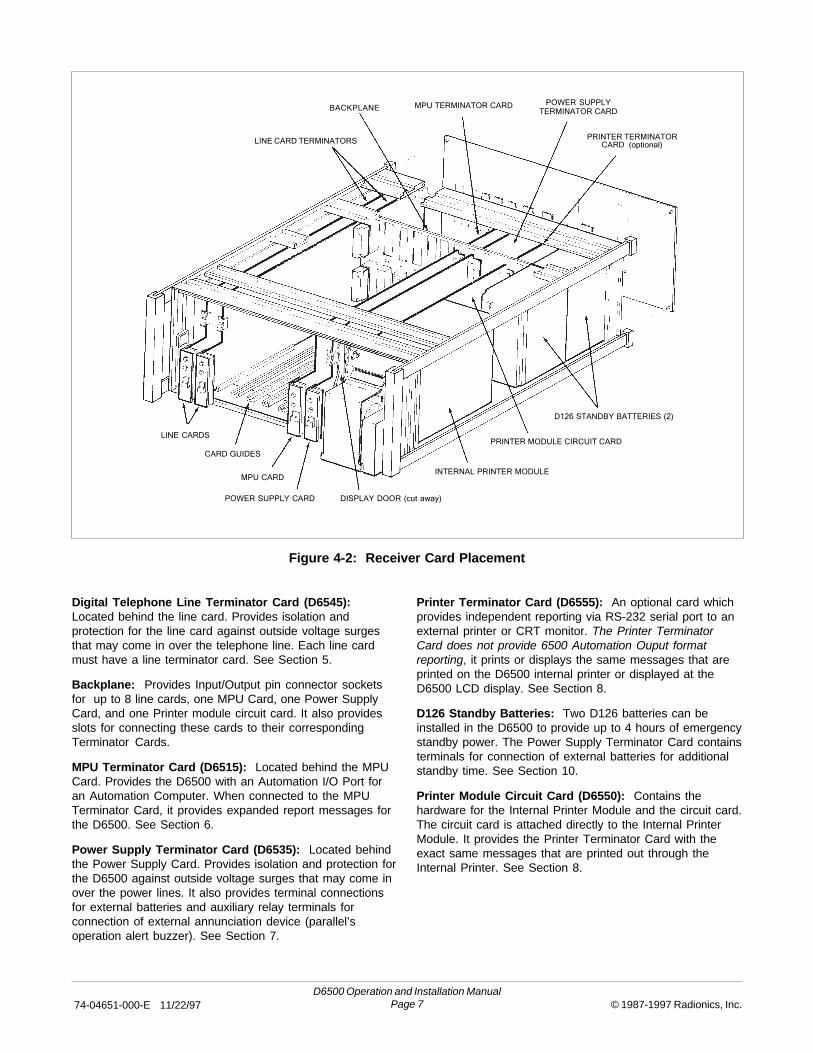
Digital Telephone Line Terminator Card (D6545):Located behind the line card. Provides isolation andprotection for the line card against outside voltage surgesthat may come in over the telephone line. Each line cardmust have a line terminator card. See Section 5.
Backplane: Provides Input/Output pin connector socketsfor up to 8 line cards, one MPU Card, one Power SupplyCard, and one Printer module circuit card. It also providesslots for connecting these cards to their correspondingTerminator Cards.
MPU Terminator Card (D6515): Located behind the MPUCard. Provides the D6500 with an Automation I/O Port foran Automation Computer. When connected to the MPUTerminator Card, it provides expanded report messages forthe D6500. See Section 6.
Power Supply Terminator Card (D6535): Located behindthe Power Supply Card. Provides isolation and protection forthe D6500 against outside voltage surges that may come inover the power lines. It also provides terminal connectionsfor external batteries and auxiliary relay terminals forconnection of external annunciation device (parallel’soperation alert buzzer). See Section 7.
Printer Terminator Card (D6555): An optional card whichprovides independent reporting via RS-232 serial port to anexternal printer or CRT monitor. The Printer TerminatorCard does not provide 6500 Automation Ouput formatreporting, it prints or displays the same messages that areprinted on the D6500 internal printer or displayed at theD6500 LCD display. See Section 8.
D126 Standby Batteries: Two D126 batteries can beinstalled in the D6500 to provide up to 4 hours of emergencystandby power. The Power Supply Terminator Card containsterminals for connection of external batteries for additionalstandby time. See Section 10.
Printer Module Circuit Card (D6550): Contains thehardware for the Internal Printer Module and the circuit card.The circuit card is attached directly to the Internal PrinterModule. It provides the Printer Terminator Card with theexact same messages that are printed out through theInternal Printer. See Section 8.
Figure 4-2: Receiver Card Placement
LINE CARD TERMINATORS
BACKPLANE MPU TERMINATOR CARDPOWER SUPPLY
TERMINATOR CARD
PRINTER TERMINATOR
CARD (optional)
D126 STANDBY BATTERIES (2)
PRINTER MODULE CIRCUIT CARD
DISPLAY DOOR (cut away)
INTERNAL PRINTER MODULE
POWER SUPPLY CARD
MPU CARD
CARD GUIDES
LINE CARDS
D6500 Operation and Installation Manual74-04651-000-E 11/22/97 Page 8 1987-1997 Radionics, Inc.
5. Digital Phone Line Cards
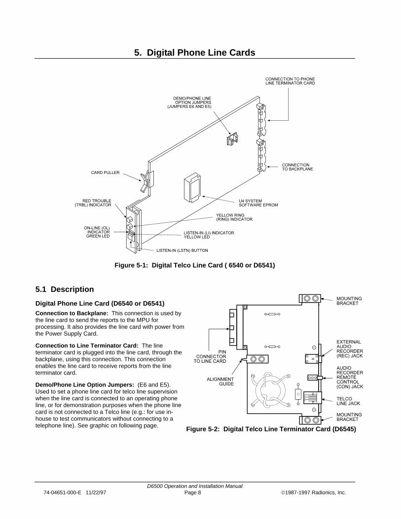
Figure 5-1: Digital Telco Line Card ( 6540 or D6541)
5.1 Description
Digital Phone Line Card (D6540 or D6541)Connection to Backplane: This connection is used bythe line card to send the reports to the MPU forprocessing. It also provides the line card with power fromthe Power Supply Card.
Connection to Line Terminator Card: The lineterminator card is plugged into the line card, through thebackplane, using this connection. This connectionenables the line card to receive reports from the lineterminator card.
Demo/Phone Line Option Jumpers: (E6 and E5).Used to set a phone line card for telco line supervisionwhen the line card is connected to an operating phoneline, or for demonstration purposes when the phone linecard is not connected to a Telco line (e.g.: for use in-house to test communicators without connecting to atelephone line). See graphic on following page. Figure 5-2: Digital Telco Line Terminator Card (D6545)

D6500 Operation and Installation Manual74-04651-000-E 11/22/97 Page 9 1987-1997 Radionics, Inc.
Place jumper plugs as shown for the desired option (re-move the sealant to change the jumper configuration).
Caution: DO NOT connect a telephone line toa phone line card when in the Demonstrationmode. A ring signal can cause serious damagethe line card.
Jumpers: (E3 and E4) Used for EPROM memoryprogramming Do not alter unless instructed by literatureor a Radionics customer service representative.
Line Card Ring Indicator (RING): This yellow indicatorlights when ringing voltage is detected on the telephoneline connected to the line card. This indicator will lightbefore each incoming call is answered by the receiver.This indicator operates even when the D6500 ispowered down or in programming mode to alert you ofincoming signals.
Listen-in Button (LSTN): The LSTN button is used tomanually transfer a line card with Listen-In informationto the Listen-In Speaker. This button is also used tomanually disconnect the D6500 from a Listen-In call inprogress. To select a card for Listen-In, press the LSTNbutton of a card in the Listen-In mode (the yellow "LI"LED will be lit). To disconnect a card, press the LSTNbutton of the line card shown in the D6500 LCD display.
On Line Indicator (OL): The green LED onthe left side of the Listen-In button lightssteadily after the receiver has answered theincoming call and flickers as data is beingreceived. This LED is active until the entiretransmission has been acknowledged and thetelephone line has returned to the on-hookcondition (ready to receive signals).
Listen-In Indicator (LI): The yellow LED onthe right side of the Listen-In button lights whenthe line card is in Listen-In mode.
Trouble Indicator (TRBL): This red indicator flickersdimly and may occasionally flash brightly while thereceiver is operating. This indicator glows steadily whenvoltage on the incoming phone line is lost, or when theDigital Telephone line card or Digital Telephone lineterminator card fails. The failure activates the reportingdevice(s) which record the troubled line and its line cardnumber (see Section 20, Troubleshooting Guide forcorrective action).
U4 System Software EPROM: Contains line cardoperating code. This EPROM is replaced during afirmware update when features are added or functionsare changed.
Line Terminator Card (D6545)Alignment Guide: Provides connection stability, andacts as a guide when connecting the Terminator Card tothe line card.
Audio Recorder Remote Control (CON) Jack: Usedto connect remote control for use in recording Listen-Inevents.
External Audio Recorder (REC) Jack: Used to recorda Listen-In session.
Mounting Brackets: Connects the Terminator Card tothe D6500 chassis and provides chassis/earthgrounding.
Pin Connector to Line Card: Provides direct interfacebetween the Terminator Card and the line card.
Telco Line Jack: A standard telephone line isconnected to this jack. This is where the D6500 firstreceives its calls from the Control/Communicator.
5.2 Card Installation
It is not necessary to disconnect power when removing,replacing or installing phone line cards (D6540 orD6541), or the phone line terminator cards (D6545)however, it is recommended that you remove powerif possible (see Section 9.6 Powering Down theReceiver). You should touch the receiver’s frame beforehandling any circuit card to discharge static electricityfrom your body.
Installing Phone Line Terminator Cards1. Remove the rear panel from the receiver.
2. Two phone line terminator cards are installed in thereceiver when it is shipped from the factory. Insert aTerminator Card in the slot next to the phone lineterminator cards which are already installed in theback of the receiver (If replacing a failed TerminatorCard, remove the defective card and insert the newcard in the same slot).
3. Align the top and bottom of the card with the cardguides in the enclosure. Slide the card into theenclosure so that the metal alignment guide pin onthe back of the Terminator Card is inserted in thehole in the back of the D6500’s backplane circuitboard.

D6500 Operation and Installation Manual74-04651-000-E 11/22/97 Page 10 1987-1997 Radionics, Inc.
4. Mount the Terminator Card in the receiver cabinetby securing the bracket screws at the top andbottom of the Terminator Card to the mounting railsat the top and bottom edges of the cabinet. Makesure the screws are firmly tightened –– the screwsprovide the ground connection required for reliablereceiver operation (see Section 22).
5. Repeat this process for all additional TerminatorCards. NOTE: Do not install spare line cards anddo not connect phone line cards to the spareTerminator Cards (see Section 22).
6. Gently pry off the appropriate plastic rectangularcover plates from the receiver rear panel so that thejacks on the cards are accessible when the rearpanel is put back in place. Secure the rear panel onthe receiver.
7. Connect appropriate telephone line cords to thePhone Line Jack on the terminator cards.
Installing Phone Line Cards
1. Install the phone line terminator card(s) asdescribed above.
2. Make sure the Demo/Phone Line option jumpers onthe line card are set appropriately (see Figure 5-1).
3. Open the display door on the receiver. Two phoneline cards are installed in the receiver when it isshipped from the factory. Slide a line card into theslot next to the line card which is presently installedin the receiver. As you look into the receiver, notethat the next available line card slot is labeled “J3”on the receiver’s backplane circuit board (J3designates this line card as Line 3, J4 as Line 4,and so on, up to J8 Line 8).
4. Load an appropriate 6500:LINE program into thereceiver (see the D6500 Program Entry Guide).
NOTE: When the line card is initialized (asindicated by a printer report) the “standard”6500:LINE program is automatically loadedinto the card. The standard programconsists of the default settings shown in theprogram entry guide.
You should not try to program or set time whilethe line cards are going through theinitialization process.
5. Check your MPU Program to insure isYes for all line cards installed, and that each linecard is connected to a phone line.

D6500 Operation and Installation Manual74-04651-000-E 11/22/97 Page 11 1987-1997 Radionics, Inc.
6. Main Processing Unit (MPU) Cards
Figure 6-1: MPU Card (D6510 or D6511)
6.1 Description
MPU Card (D6510 or D6511)Automation System Data In Monitor:(DS1,Yellow LED): This LED is normally lit. Asdata is received from the automation system,this LED begins to flicker or becomes dim.
Automation System Data Out Monitor: (DS2,Green LED): This LED is normally lit. As data istransmitted to the automation system, this LEDbegins to flicker or becomes dim.
Connection to Backplane: This connectionprovides interface for information coming fromthe line card and provides the MPU Card withpower from the Power Supply Card.
Connection to MPU Terminator Card: TheMPU Terminator Card is plugged into the MPUCard, through the backplane using thisconnection. The MPU Card sends the MPUTerminator Card information for AutomationFormat messages that the MPU Card receivedfrom the line card.
D5200 Programmer Jack: Used to connectthe D5200 Programmer to the D6500 forprogramming the MPU and line cards.
Figure 6-2: MPU Terminator Card (D6515)
D6500 Operation and Installation Manual74-04651-000-E 11/22/97 Page 12 1987-1997 Radionics, Inc.
Memory Size Select Jumper: (P1) Should always bein 8K position.
Microprocessor Reset Button: (S2) Pressing thisbutton initiates a warm restart on the receiver. Theprogram does not default, but the current signals andclock settings are erased.
Caution: DO NOT press this button unlessdirected to do so by Radionics personnel.Never press this button while the printer isprinting, or when the printer paper is jammed.
Printer Indicator (PNTR): This red indicator lights toindicate that the internal or external printer has failed.The PNTR indicator lights steadily when the internalprinter is out of paper.
Ribbon Cable Socket: (J3) Fourteen conductor cable.For connection to the LCD Display on the front of theD6500.
System Indicator (SYS): This red indicator lights whena system failure has occurred or when the buffercontains 500 events (436 external messages, 64internal messages).
Caution: When this indicator lights duringoperation, DO NOT power down the D6500 orremove the MPU. This could result in the lossof stored information.
System Software EPROMs: (J21/U21, J20/U20, andJ32/U32 on the D6511) Contains MPU Card operatingcode. These EPROMs are sometimes replaced during afirmware update when features are added or functionsare changed.
TEST Button: The TEST button is used to initiateseveral functions of the D6500.
1. The TEST button is used to initiate a reportingdevice (printer) test. A message for the testappears on the receiver’s display and is also sent toall primary devices. The D6500’s internal printerprints the following to indicate a test:
MM/DD HH:MM L8 ACCT 888 [TEST] ZN 8(Actual Date and Time)
2. The TEST button is used to set the date and time inthe D6500 (see Section 11, Clock and CalendarControls).
3. The TEST button and SLNC buttons are pressedsimultaneously to initiate/terminate the D6500’sprogramming mode (see Section 12 for additionalprogramming instructions).
Time Set Toggle Switch: Used to set the D6500internal clock. To set the time and date, refer to Section11.
MPU Terminator Card (D6515)Alignment Guide: Provides connection stability, andacts as a guide when connecting the terminator card tothe MPU Card.
Automation Computer (COMP RS-232) Port: Anauxiliary RS-232 Port for connection to a computerterminal or to an automation computer for SIA/6500mode Automation format reporting.
Configuration Jumpers: (J3) Lets you set up the RS-232 Data I/O protocols for Automation format reporting.For information on configuring J3, refer to the D6500Computer Interface Installation Manual (74-05313-000).The D6500 can provide the following protocols:
• TXD and RXD (Transmit and Receive Data)• RTS/CTS (Ready to Send/Clear to Send)• DSR/DTR (Data Set Ready/Data Terminal Ready)
Caution: If you are not connecting anautomation computer to this port, LEAVETHESE JUMPERS IN THE STANDARDPOSITION AS SHIPPED. Certain jumperconfigurations could cause permanent damageto the RS-232 output and may also damageother components in the D6500.
Mounting Brackets: Connects the terminator card tothe D6500 chassis and provides chassis/earthgrounding.
Pin Connector to MPU Card: Provides direct interfacebetween the terminator card and the MPU Card.
6.2 Card Removal and Replacement
The D6500 must be powered down before removing,replacing or installing the MPU Card (D6510 or D6511)or the MPU terminator card (D6515).
Removing the MPU Card1. Power down the Receiver (see Section 9.6,
Powering Down the Receiver).
2. Carefully grasp the metal front edge of the MPUCard and slide it two or three inches out of theenclosure.
3. Unplug the ribbon cable connecting the LCDdisplay to the MPU Card. Use caution whendisconnecting this cable. BE CAREFUL NOT TOBEND THE BOARD. Grasp the plastic plugconnected to the MPU board at the end of the cableand gently pull it away from the plane of the circuitboard (see Figure 7-3).
4. Pull the MPU Card straight out of the card guide.

D6500 Operation and Installation Manual74-04651-000-E 11/22/97 Page 13 1987-1997 Radionics, Inc.
Replacing the MPU Card1. Power down the Receiver (see Section 9.6,
Powering Down the Receiver).
2. Remove the defective MPU Card from theenclosure as described above.
3. Align the top and bottom of the MPU Card with thecard guides. Slide the card into the enclosure.
4. Re-connect the ribbon cable to the MPU Card.Orient the cable so that it comes off of the MPUCard toward the front of the receiver.
5. Power-up the Receiver and re-load the customized6500:MPU and 6500:LINE programs from theD5200 programmer (see Sections 9.6 and 12).
NOTE: Do not try to program or set time while thecards are going through the initializationprocess.

D6500 Operation and Installation Manual74-04651-000-E 11/22/97 Page 14 1987-1997 Radionics, Inc.
7. Power Supply Cards
Figure 7-1: Power Supply Card ( D6530)
7.1 Description
Power Supply Card (D6530)AC Indicator (AC): This green indicator is lit while thereceiver is operating on AC power. If AC power is lost,this indicator begins to blink and the receiverautomatically switches to battery standby (see Section10).
AC Slide Switch: (S1) In the OFF position (down) itdisconnects AC power at the Power Supply Card. (ACpower continues to be supplied to the Power SupplyTerminator Card until the AC transformer isdisconnected.)
Battery Indicator (BAT): This red indicator lights whenthe battery is low or when the battery is missing (seeSection 10).
Connection to Backplane: Through this connection,the Power Supply Card provides power to all of theCards and Modules in the D6500. Figure 7-2: Power Supply Terminator Card (D6535)

D6500 Operation and Installation Manual74-04651-000-E 11/22/97 Page 15 1987-1997 Radionics, Inc.
Connection to Power Supply Terminator Card: ThePower Supply Card is plugged into the Power SupplyTerminator Card, through the backplane, using thisconnection. This connection provides power to thePower Supply Card from the Power Supply TerminatorCard.
Battery Switch: (S2) In the OFF position (down), itdisconnects battery power at the Power Supply Card.Battery power is supplied by the D126 StandbyBatteries or the external DC power supply. Batterypower continues to be supplied to the terminator carduntil all DC sources are physically disconnected.
Latching Ribbon Cable Connector: (J4) Forconnection to Listen-In/Talk-Back controls on thedisplay door.
Pin Connector Jack: (J5) Four-pin Connector forwiring harness which supplies backlight power todisplay panel LCD.
Silence Button (SLNC): The SLNC button is used toinitiate several functions of the D6500:
1. Press this button to silence the operator alertbuzzer.
2. In the Manual Mode, press the SLNC button to viewand display additional messages received.
3. The SLNC and TEST buttons are pressedsimultaneously to initiate/terminate the D6500’sprogramming mode.
4. The SLNC button is used to initiate Manual SystemTests (see Section 13 for details).
Power Supply Terminator Card (D6535)Alignment Guide: Provides connection stability andacts as a guide when connecting the terminator card tothe MPU Card.
AC Power Circuit Breaker: (CB1) A reset button forthe AC power is also located on this Circuit Breaker.
AC Power Transformer Jack: Used to connect theD1650 Transformer.
Auxiliary Relay Terminals: Terminals 3 and 4 are forconnection of auxiliary device (e.g.: external buzzer).Relay operation parallel’s operator alert buzzer. Relay isdry contact, Form C, 2 amp rating @24VAC or 24VDC.
D126 Battery Circuit Breakers: (CB3, CB4) Resetbuttons for the D126 batteries are also on these CircuitBreakers.
External Battery Circuit Breaker: (CB2) A resetbutton for the external battery is also located on thisCircuit Breaker.
External Battery Terminals: Terminals for connectionof external DC supply: Terminal #1 is negative (-),Terminal #2 is positive (+).
Mounting Brackets: Connects the terminator card tothe D6500 chassis and provides chassis/earthgrounding.
Pin Connector to Power Supply Card: Providesdirect interface between the terminator card and thePower Supply Card.
Plug-In Connector for Battery Leads: Parallel wiringconnection to D126 batteries. Red = Positive (+), Black= Negative (-).
7.2 Card Removal and Replacement
Caution: The D6500 must be powered downbefore removing, replacing or installing thePower Supply Card (D6530), or the PowerSupply Terminator Card (D6535).
Touch the receiver’s frame before handling any circuitcard to discharge static electricity from your body.
Removing the Power Supply Terminator Card1. Power down the Receiver (see Section 9.6,
Powering Down the Receiver).
2. Unplug the AC transformer connector from thecard: Squeeze the top and bottom of the plug torelease it from the socket on the card.
3. Remove the Rear Panel from the receiver.
4. Disconnect the leads from the external standbybattery (terminals 1 & 2 on Power SupplyTerminator Card).
WARNING: To avoid electrical shock,disconnect the battery leads or switch off thepower supply before handling the leadsconnected to these terminals.
5. Unplug the standby battery connector on the PowerSupply Terminator Card (connector J3).
6. Unscrew the screws from the mounting brackets atthe top and bottom of the terminator card.
7. Pull the terminator card straight out of the cardguide.

D6500 Operation and Installation Manual74-04651-000-E 11/22/97 Page 16 1987-1997 Radionics, Inc.
Replacing the Power Supply Terminator Card1. Power down the Receiver (see Section 9.6,
Powering Down the Receiver).
2. Remove the defective Power Supply Terminatorfrom the enclosure as described above.
3. Align the top and bottom of the terminator card withthe card guides in the enclosure. Slide the card intoplace.
4. Mount the terminator card in the receiver cabinet bysecuring the bracket screws at the top and bottomof the terminator card to the mounting rails at thetop and bottom edges of the cabinet. Make sure thescrews are firmly tightened –– the screws providethe ground connection required for reliable receiveroperation (see Section 22 for further information).
5. Re-connect appropriate wires to the externalbattery/external buzzer terminals on the terminatorcard.
WARNING: To avoid electrical shock,disconnect the battery leads or switch off thepower supply before handling the leadsconnected to the external standby batteryterminals.
6. Re-connect the standby battery connector to the J3connector on the Power Supply Terminator Card.
7. Replace the rear panel.
8. Plug the AC transformer into the transformer socketon the Power Supply Terminator Card.
9. Return the AC and BAT switches to the ON (up)position.
Removing the Power Supply Card1. Power down the Receiver (see Section 9.6,
Powering Down the Receiver).
2. Remove the Printer Module from the receiver (seesection 8.2).
3. Reach into the Printer Module compartment:
a. Unplug the wiring harness from the 4-wire PinConnector Jack near the front of the PowerSupply Card.
b. Unplug the wiring harness from the LatchingRibbon Cable Connector on the Power SupplyCard. You must push open the socket’s endtabs to eject the wiring harness from thesocket.
4. Unplug the ribbon cable from the Ribbon CableConnector socket on the MPU Card. Use cautionwhen disconnecting this cable. Do not pull on thecable while unplugging it. Grasp the plastic plug atthe end of the ribbon cable and gently pull it awayfrom the plane of the MPU circuit board (see Figure7-3).
5. Slowly pull the Power Supply Card straight out ofthe card guide.
Replacing the Power Supply Card1. Power down the Receiver (see Section 9.6,
Powering Down the Receiver).
2. Remove the defective Power Supply Card from theenclosure as described above.
3. Align the top and bottom of the Power Supply Cardwith the card guides. Slide the card into theenclosure.
4. Re-connect the wiring harnesses to the 4-wire andLatching Ribbon Cable Connector on the PowerSupply Card.
5. Re-connect the ribbon cable to the MPU Card.Orient the cable so that it comes off of the MPUCard toward the front of the receiver.
6. Put the Printer Module back into the enclosure andturn on the Printer Control Switch.
7. Power-up the receiver.

D6500 Operation and Installation Manual74-04651-000-E 11/22/97 Page 17 1987-1997 Radionics, Inc.
Figure 7-3: Power Supply and MPU Card Connectors and Switches (cut-away view)

D6500 Operation and Installation Manual74-04651-000-E 11/22/97 Page 18 1987-1997 Radionics, Inc.
8. Printer Specifications
Figure 8-1: Printer Module (front view) (D6550)
Figure 8-2: Printer Module (side view)

D6500 Operation and Installation Manual74-04651-000-E 11/22/97 Page 19 1987-1997 Radionics, Inc.
8.1 Description
Printer Module (D6550)Caution: If it is ever necessary to return thePrinter Module to Radionics for repair, it MUSTbe packaged carefully. Excessive stress placedon the printed circuit board may cause hairlinefractures in the board, making it non-repairable.
Circuit Breaker Reset Button: Resets the circuitbreaker (CB1) (-26V supply) for stalled print head.
Connection to Backplane: This connection providesinterface between the Printer Module and the MPU Cardfor printing requests.
Connection to Optional Printer Terminator Card:The Printer Module is plugged into the PrinterTerminator Card, through the backplane, using thisconnection. The Printer Module, together with the printerterminator card, allows reports to be sent to theexternal printer as programmed.
Cutting Bar: For cutting the internal printer paper.
Data-In Monitor: (DS1, Yellow LED) RS232 Data-InMonitor for an external printer or Auxiliary CRT (onsolder side of board).
Data-Out Monitor: (DS2, Green LED) RS232 Data-OutMonitor for an external printer or Auxiliary CRT (onsolder side of board).
Paper Advance Thumbwheel: Use the thumbwheel(located on the right side of the front of the printer) tomanually feed the paper through the printer.
Paper-Feed Spindle Knob: Holds the paper roll on thePaper Feed Roll.
Paper Retaining Bar: Holds the paper against thepaper sensor contacts.
Paper Sensor: The paper sensor is four copper-cladstrips attached to the front of the printer just under thepaper input slot. Two strips are ground and two stripswork as the paper sensor. If a message is received, it isdisplayed on the LCD and printed out on the internalprinter. If the paper fails to make contact with the papersensor and ground, the printer will attempt to print themessage. If paper is not sensed, the D6500 generatesa line feed and checks again to see if paper is sensed. Ifpaper is sensed, the D6500 resumes normal operation(refer to the Computer Interface Manual for operationsusing specific programming options).
The writing platen on the Paper Take-up Spoolassembly must be fully closed to hold the paper againstthe Paper Sensor (see Section 8.4 for instructions onchanging the printer paper).
Paper Take-up Spool: The Paper Take-up Spool is abuilt-in feature of the D6500. When the Spool Switch isin the AUTO position the Paper Take-up Spoolautomatically spools the printer paper as messages areprinted. The Paper Take-up Spool assembly alsoprovides a convenient writing platen.
Printer Buzzer: Sounds when the circuit breaker trips.
Printer Control Switch: This switch controls the flowof data to the printer (it is NOT a power switch). In theUp position the printer is able to receive data, in theDown position the printer is disabled. To changeposition of the switch, you must first pull it away from thefaceplate and then place it in the desired position.
Spool Switch: In the Up (Off) position, the automaticpaper take-up spool is disabled. In the Middle (AUTO)position the paper take-up spool operates automaticallyand spools the paper as messages are printed. In theDown (MAN) position, the spool motor is activated totake-up any slack in the paper.
Take-Up Spindle Knob: Holds the paper spool on thePaper Take-Up Spool.
Thumbwheel Release Lever: This lever (located onthe lower left front of the printer) releases the pressureon the printer paper, so you may remove paper orthread new paper into the printer.
8.2 Module Removal and Replacement
Caution: The D6500 must be powered downbefore removing or replacing the PrinterModule (D6550). Touch the receiver’s framebefore handling any circuit card to dischargestatic electricity from your body.
Removing the Printer Module1. Power down the receiver (see Section 9.6,
Powering Down the Receiver).
2. Loosen the screws at the top of the Printer Module.
3. Grasp the lower edge of the Writing Platen/PaperTake-Up Spool assembly and slowly pull the Printermodule out of the receiver’s enclosure.
Replacing the Printer Module1. Power down the receiver (see Section 9.6,
Powering Down the Receiver).
2. Remove the defective printer as described above.
3. Align the top and bottom of the Printer Modulecircuit card with the card guides in the printercompartment. Slide the Printer into thecompartment.
4. Tighten the screws at the top of the Printer Module.Power-up the receiver.
5. Make sure the Printer Control Switch is in the ONposition. Press the TEST button, on the front of theMPU Card, to initiate a printer test.
D6500 Operation and Installation Manual74-04651-000-E 11/22/97 Page 20 1987-1997 Radionics, Inc.
6. Power up the receiver by simultaneously switchingon the AC and BAT switches on the power supplycard.
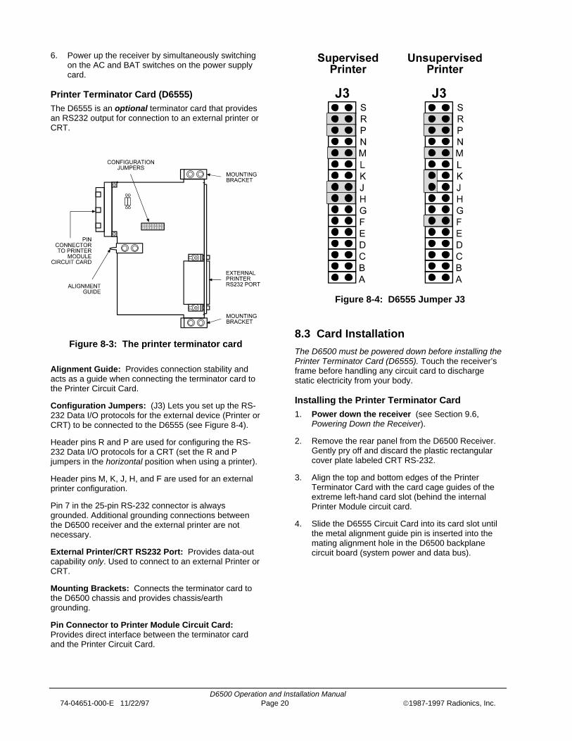
Printer Terminator Card (D6555)The D6555 is an optional terminator card that providesan RS232 output for connection to an external printer orCRT.
Figure 8-3: The printer terminator card
Alignment Guide: Provides connection stability andacts as a guide when connecting the terminator card tothe Printer Circuit Card.
Configuration Jumpers: (J3) Lets you set up the RS-232 Data I/O protocols for the external device (Printer orCRT) to be connected to the D6555 (see Figure 8-4).
Header pins R and P are used for configuring the RS-232 Data I/O protocols for a CRT (set the R and Pjumpers in the horizontal position when using a printer).
Header pins M, K, J, H, and F are used for an externalprinter configuration.
Pin 7 in the 25-pin RS-232 connector is alwaysgrounded. Additional grounding connections betweenthe D6500 receiver and the external printer are notnecessary.
External Printer/CRT RS232 Port: Provides data-outcapability only. Used to connect to an external Printer orCRT.
Mounting Brackets: Connects the terminator card tothe D6500 chassis and provides chassis/earthgrounding.
Pin Connector to Printer Module Circuit Card:Provides direct interface between the terminator cardand the Printer Circuit Card.
Figure 8-4: D6555 Jumper J3
8.3 Card Installation
The D6500 must be powered down before installing thePrinter Terminator Card (D6555). Touch the receiver’sframe before handling any circuit card to dischargestatic electricity from your body.
Installing the Printer Terminator Card1. Power down the receiver (see Section 9.6,
Powering Down the Receiver).
2. Remove the rear panel from the D6500 Receiver.Gently pry off and discard the plastic rectangularcover plate labeled CRT RS-232.
3. Align the top and bottom edges of the PrinterTerminator Card with the card cage guides of theextreme left-hand card slot (behind the internalPrinter Module circuit card.
4. Slide the D6555 Circuit Card into its card slot untilthe metal alignment guide pin is inserted into themating alignment hole in the D6500 backplanecircuit board (system power and data bus).

D6500 Operation and Installation Manual74-04651-000-E 11/22/97 Page 21 1987-1997 Radionics, Inc.
5. Secure the Mounting Brackets at the top andbottom corners of the Terminator Card to the upperand lower mounting rails inside the D6500 cabinet.Make sure the screws are firmly tightened–thescrews provide the ground connection required forreliable receiver operation.
6. Re-install the rear panel of the receiver and secureit in place with the four mounting screws, one ineach corner.
8.4 Changing the Internal PrinterPaper
The Internal Printer in the D6500 receiver uses a specialelectro-conductive paper to record data. Use onlyRadionics D6007 Printer Paper. The Internal Printer hasa copper paper sensor which makes contact with theshiny side of the electro-conductive paper. The InternalPrinter shuts off when the Paper Sensor does not makecontact with the paper. If other reporting devices arefunctioning, a message indicating the failed device isprinted/displayed if Internal Printer Supervision( ) is enabled (see the D6500 Program EntryGuide). If the internal printer is the only reporting deviceand it shuts off, the receiver switches to the ManualMode of operation. The status line of the LCD willdisplay Check Internal Printer.
NOTE: The take-up spool writing platen is secured tothe printer module by a hinge on its lower edge.The writing platen is held in position by a springlatch. To access the paper spindles you mustpull the top of the writing platen away from thefront of the receiver.
Changing the Paper1. Set the Printer Control Switch to the OFF position.
Gently pull the switch away from the face of thereceiver then place the switch in the OFF position(down).
2. Feed the last few inches of paper through theprinter. Rotate the thumbwheel (using a downwardstroke) until the end of the paper comes out of theprinter. [If the thumbwheel does not work, push upthe black plastic lever on the left side of the printer(Release Lever) and manually pull the paper out ofthe printer.]
NOTE: Always use the thumbwheel to advancethe paper – do NOT pull the paper.
3. Remove the empty paper core from the paper feedspindle on the printer. Turn the spindle knobcounter-clockwise until it is free from the spindle.Slide the empty paper core off of the spindle. Savethe empty paper core –– you will re-install it on thetake-up spindle to provide a core for the next roll ofpaper.
4. Put a new roll of electro-conductive paper on thepaper feed spindle. Make sure that the paper ispositioned so the shiny side faces the PaperSensor when the paper is threaded into the printer.Put the knob back on the paper feed spindle.Rotate the knob clockwise to tighten it.
5. Thread the paper into the printer. Run the paper offthe front of the paper feed roll and around thebottom of the back lash bar, then up and over thePaper Sensor and into the lower slot of the printer(see Figure 8-5). Advance the paper with thePaper Advance Thumbwheel (using a downwardstroke) until the paper comes out the top of theprinter. If the thumbwheel does not work, push upthe black plastic Thumbwheel Release Lever on theleft side of the printer so you can thread the paperinto the printer.
Figure 8-5: Changing the Internal PrinterPaper
6. Your receiver is equipped with a Paper Take-upSpool. It automatically rewinds the printed copy ofthe receiver activity reports. Remove the roll ofused paper from the Paper Take-up Spool and“start” the new roll.
a. Hold the center of the Take-Up Spindle. Turnthe knob counter-clockwise to remove it fromthe spindle.
b. Firmly grasp the old roll of used paper and pullit off of the spindle.
c. Slide an empty paper core (see step 3) ontothe take-up spindle.
D6500 Operation and Installation Manual74-04651-000-E 11/22/97 Page 22 1987-1997 Radionics, Inc.
d. Secure the end of the new paper roll to thepaper core on the take-up spindle (useadhesive tape).
e. Put the Spindle Knob back onto the Take-UpSpindle. Hold the center of the Take-UpSpindle and rotate the knob clockwise totighten it.
f. Return the writing platen to its normal position,making sure the magnet latches the platen inplace.
7. Set the Printer Control Switch to the “ON” position.Gently pull the switch away from the face of thereceiver, lift it upward. Release the switch leverwhen it is in the ON (up) position.
8. Test the printer. Press the TEST button on thefront of the MPU Card. The printer should print thefollowing test message:
MM/DD HH:MM L8 ACCT 888 [TEST] ZN 8(MM/DD is the date, HH:MM is the time.)
TroubleshootingIf the printer doesn’t work after the paper has beenchanged:
1. Make sure the Printer Control Switch is in the “ON”position (UP).
2. Make sure that the shiny side of the paper makesgood contact with the paper sensor. If the writingplaten is not fully closed, the paper may not makeproper contact with the sensor. Press the writingplaten toward the front of the receiver and makesure the catch holds the platen in place.
3. Check for paper jams: NEVER pull the paper downor sideways, this could cause a jam.
a. Change the Printer Control switch to the “OFF”(down) position.
b. Remove the plastic paper cutting bar by gentlypushing it to the left and pulling it toward you.
c. Press the Release Lever to relieve pressure onthe paper.
d. Remove jammed paper –– Use a can of DRYcompressed air (available from photographicsupply houses) to blow dust and scraps ofpaper from the printer.
Caution: Do not use paper clips or othermetallic instruments to remove jammed paper.Do not use ordinary compressed air––moisturein it could damage the printer circuits.
e. Gently snap the cutting bar into place after thejam is cleared and turn the Printer Controlswitch “ON.”
8.5 External Printers Supported
An external printer can be connected to the RS-232 portwith a 25-pin serial cable (maximum 50 feet). Theexternal printer can operate in a supervised orunsupervised mode. The unsupervised mode isprovided for use with printers that cannot supply theDTR handshake signal or hardware supervision. If theprinter supplies XON/XOFF, the printer is supervised forpaper out and online/offline conditions. In unsupervisedmode, the cable between the receiver and the printerand the condition of AC power loss are not supervised.
In supervised mode, printer trouble is reported forprinter offline, loss of AC power, paper out, anddisconnected cable. The supervised mode must beused for UL installations. The D6500 receiver supportsthe following printers in supervised mode.
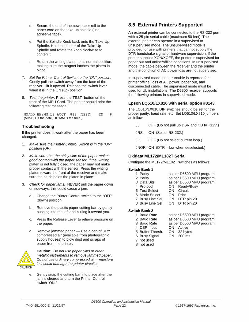
Epson LQ510/LX810 with serial option #8143The LQ510/LX810 DIP switches should be set for theproper parity, baud rate, etc. Set LQ510/LX810 jumpersas follows:
J5 OFF (Do not pull up DSR and CD to +12V.)
JRS ON (Select RS-232.)
JC OFF (Do not select current loop.)
JNOR ON (DTR = low when deselected.)
Okidata ML172/ML182T SerialConfigure the ML172/ML182T switches as follows:
Switch Bank 11 Parity as per D6500 MPU program2 Parity as per D6500 MPU program3 Data Bits as per D6500 MPU program4 Protocol ON Ready/Busy5 Test Select ON Circuit6 Mode Select ON Print7 Busy Line Sel ON DTR pin 208 Busy Line Sel ON DTR pin 20
Switch Bank 21 Baud Rate as per D6500 MPU program2 Baud Rate as per D6500 MPU program3 Baud Rate as per D6500 MPU program4 DSR Input ON Active5 Buffer Thresh. ON 32 bytes6 Busy Signal ON 200 ms7 not used8 not used

D6500 Operation and Installation Manual74-04651-000-E 11/22/97 Page 23 1987-1997 Radionics, Inc.
Okidata ML320 SerialConfigure the ML320 as follows:
Parityas per D6500 MPU programSerial Data 7 or 8 bits as per D6500 MPU programProtocol Ready/BusyDiagnostic Test NoBusy Line DTRBaud Rate as per D6500 MPU programDSR Signal ValidDTR Signal Ready on Power UpPrint Mode UtilityBusy Time 200 ms
8.6 External Printer Reports
A sample external printer report is shown in Figure 8-6.The sequence of reports from the external printer areoldest at top and newest at bottom, whereas reportsfrom the D6500 internal printer read from bottom(oldest) to top (newest).
Oldest Report07/29 13:20 L2 ACCT 812 CLOSING ZONE B07/29 13:21 L2 ACCT 812 ALARM ZONE 107/29 13:22 L2 ACCT 812 RESTORAL ZONE 107/29 13:22 L2 ACCT 812 CANCEL REPORT07/29 13:22 L2 ACCT 812 OPENING ZONE B07/29 13:22 L2 ACCT 812 TROUBLE ZONE F07/29 13:23 L2 ACCT 812 RESTORAL ZONE FNewest Report
Figure 8-6: EXTERNAL PRINTER REPORTS

D6500 Operation and Installation Manual74-04651-000-E 11/22/97 Page 24 1987-1997 Radionics, Inc.
9. Installation
9.1 UL Installations
Radionics has always taken the position that in thecentral station environment a spares package orredundant receiver was a necessity to ensure optimumcentral station protection.
WARNING: However, Underwriters'Laboratories (UL) Standard 611 paragraph28.1, requires that any central station listed forNFPA 71.5, Burglary or Central StationProtective Signaling, must have a redundantreceiver on premises to be used in the eventthat the primary receiver fails or malfunctions.
One spare receiver may serve as a backup for amaximum of five active receivers.
UL Standard 611 paragraph 28.1 also states that youmust be able to switch from one receiver to a stand byreceiver within 30 seconds, and repair the faultyreceiver and return it to service within 30 minutes (thisrequires a D6500 spares package).
While it is perfectly acceptable to back up a D6000 witha D6500, there are certain situations whereincompatibilities will arise when backing up the D6500with the D6000. When using Modem or 3x2, 4x1, and4x2 pulse formats, it is impossible to use the D6000 toback up the D6500. The D6000, in all cases, is onlycapable of reporting ten zones of alarm, trouble, andrestoral information and can only support three digitaccount numbers and one digit zone #'s.
To satisfy this requirement, it is Radionics policy torecommend the use of a D6500 receiver as a back up ifthe primary receivers are D6500s. Use of four digitaccount numbers (communicating in a RadionicsModem format) or reporting ZONEX or COMEX requiresa D6500 receiver for redundancy.
If you have any questions, please call RadionicsTechnical Support or your regional manager.
9.2 Burglar Alarm Applications
The D6500 Receiver is intended to be installed inaccordance with UL Standard 611 for Central StationBurglar Alarm Systems and/or UL Standard 365 PoliceStation Burglar Alarm Systems. To supervisecertificated accounts this receiver must be used in acentral station which has backup AC power incompliance with NFPA 71. The internal batteries do notprovide sufficient operating time to comply with thereferenced standards. Terminals for connection of anexternal DC power supply are provided in the rear of thereceiver (see Section 10).
9.3 Fire Alarm Applications
The D6500 Receiver is suitable for Central StationProtective Signaling when it is installed and used in
compliance with NFPA Standard No. 71 or NFPA 72(chap. 8) and ANSI/NFPA 70-1984 Article 760.Installation limits for Digital Alarm CommunicatorReceivers (DACR) are under the jurisdiction of yourlocal authority.
9.4 Installation Check List
[ ] 1. The D6500 Receiver is shipped with a 16 VACClass 2 transformer (D1650), two 12 VDC, 7Ah batteries (D126) and rack mount hardware.
[ ] 2. Open the door of the display panel and locatethe Power Supply Card. Make sure that the ACand the BAT power switches on the right sideof the Power Supply Card are OFF (bothswitches in the down position, see Figure 9-1).
[ ] 3. Check each of the receiver’s cards to see thatthey are properly positioned in the card guidesat the top and bottom of the enclosure and thatthe connections have not become loose inshipment.
[ ] 4. Loosen the screws at each corner of the rearpanel. Remove the rear panel from thereceiver.
[ ] 5. Connect a grounding wire to the threadedEarth Ground post on the receiver cabinetframe near the Power Supply terminator card(see Figure 9-2). The grounding wire should be16 AWG or heavier. Secure the wire to the postusing the washer and nut provided. Run thegrounding wire through the EARTH GND cut-out on the receiver’s rear panel. Secure thegrounding wire to a good earth ground (seesection 22. Central Station Tips for details onproper grounding of the D6500).
[ ] 6. There are four screw terminals on the PowerSupply terminator card (see Figure 9-2). Makethe appropriate connections to these terminalsas outlined below:
a. Terminals 1 (- negative) and 2 (+ positive) onthe Power Supply terminator card allow thereceiver to be connected to an external D.C.power supply (see section 10 Standby Power).If you will be using an external D.C. powersupply for emergency standby power, run theconnecting wires through the EXT BAT cutouton the receiver’s rear panel when you installthe receiver.
b. Terminals 3 and 4 on the Power SupplyTerminator Card provide a dry contact relayoutput which is closed while the operator alertbuzzer is activated (see section 10, StandbyPower). If you are connecting the relay output

D6500 Operation and Installation Manual74-04651-000-E 11/22/97 Page 25 1987-1997 Radionics, Inc.
to an external device, run the wires through the EXT BUZ cutout on the receiver’s rear panel.
Figure 9-1: D6500 receiver front section controls and indicators (display door open)
Figure 9-2: D6500 receiver, rear view (rear panel open)
[ ] 7. Install the two D126 Standby Batteries in thereceiver. A Battery Retaining Bracket is
installed at the back of the battery compart-ment. Loosen the screws at the top and bottomof the bracket to remove it from the enclosure.

D6500 Operation and Installation Manual74-04651-000-E 11/22/97 Page 26 1987-1997 Radionics, Inc.
a. Connect the black battery leads from thePower Supply Terminator Card to the blackterminals on the batteries.
b. Connect the red battery leads from the PowerSupply Terminator Card to the red terminals onthe batteries.
c. Turn one of the batteries on end so that theterminals are near the top of the battery. Withthe terminals facing the front of the receiver,slide the battery into the battery slot (seeFigure 4-2).
d. Turn the other battery on end so that theterminals are near the top of the battery. Withthe terminals facing the rear of the receiver,slide the battery into the battery slot (seeFigure 4-2).
e. Re-install the Battery Retaining Bracket.
[ ] 8. The D6500 receiver comes equipped with twoD6540 or D6541 Digital Telephone line cardsand two D6545 Digital Telco Terminator Cards.If you are going to install additional line cards,install the terminator cards now.
[ ] 9. If you installed additional Line terminator cards(in step 8 above) you can now install the linecards (see Section 5.2).
[ ] 10. You may also want to install the Lineterminator card(s) from your SparesPackage(s) so that in the event of a failure,you may quickly switch over to the replacementcard. (See Section 5.2 for the installationprocedure.)
NOTE: You may install “spare” Line terminator cards,however do not install "spare" line cards (seeSection 22, Central Station Tips).
[ ] 11. Connect 4 or 6 conductor phone cord(s) to theRJ11C jack(s) of the desired phone line(s).Plug the other end of the modular phonecord(s) into the TELCO Jack on theappropriate line terminator card(s).
[ ] 12. Plug the Transformer’s Power Connector pluginto the “POWER 16.5 VAC 50VA 60 Hz”socket on the back of the receiver. Plug thetransformer into a properly wired 120VAC 60HZ outlet (Standard AC outlet). Make sure theoutlet is not controlled by a switch!
[ ] 13. Simultaneously switch the AC and BAT slideswitches on the Power Supply card ON (to the“up” position).
NOTE: If Battery Missing or Battery Trouble is reportedwhen you power up, allow the receiver tooperate on AC power for several hours torecharge the batteries before troubleshooting alow battery condition.
[ ] 14. Perform a “Manual System Test” to ensure thatall connections are secure and that all
components are operating properly (seeSection 13 for instructions).
[ ] 15. Load your customized 6500:MPU and6500:LINE Programs into the receiver (seeSection 12 for details).
[ ] 16. Set the Calendar and Clock to the correct dateand time (see Section 11). Close the displaydoor.
[ ] 17. To ensure that communication formats arecorrect, test the receiver by havingcommunicators transmit reports to each lineconnected to the receiver.
9.5 Rack Mount Instructions
Rack mounting hardware is included with the D6500.When mounted in a rack, the receiver’s Class 2transformer may be plugged into an outlet inside therack only if the outlet is wired in accordance with Article760 of the National Electrical Code. Underwriters’Laboratories specifications require that the receiverbe wired by trained commercial professionals andconnected through a transformer directly into a120VAC 60 Hz electrical supply. DO NOT connectthe D6500 to an outlet that is controlled by a switch.
[ ] 1. The side panels are secured to the enclosureframe with Velcro™ fasteners. Insert a flat-bladed screwdriver in the slot on the rear edgeof the receiver side panel and pry each of thepanels off.
[ ] 2. On each side of the frame (near the front edge)are two threaded holes. Align the holes in therack mount “ears” with the holes in the receivercabinet frame. Use the screws provided tosecure the ears to the receiver.
[ ] 3. A shelf or bracket MUST be installed at theback of the rack to support the receiver.
Caution: The front mounting ears CANNOTsupport the full weight of the D6500. A supportshelf or bracket must be installed.

D6500 Operation and Installation Manual74-04651-000-E 11/22/97 Page 27 1987-1997 Radionics, Inc.
9.6 Powering Down the Receiver
The D6500 must be powered down before installing,removing, or replacing components.
NOTE: Incoming calls illuminate the RING indicator onthe line card, even when the receiver is powereddown.
1. Open the front of the receiver.
2. Remove battery power: Slide the BAT switch on thePower Supply Card to the OFF (down) position.
3. Remove AC power: Slide the AC slide switch on thePower Supply Card to the OFF (down) position.
4. Unplug the AC transformer from the 120 volt outlet.
To power up the receiver after installing or replacingcomponents, follow steps 12 through 17 in section 9.4,Installation Checklist.

D6500 Operation and Installation Manual74-04651-000-E 11/22/97 Page 28 1987-1997 Radionics, Inc.
10. Standby Power
During loss of AC power, the receiver automaticallyswitches to standby power supplied by two D126Standby batteries. As long as there is adequate standbypower available from the D126 batteries, there is nointerruption of the receiver’s operation even if the powerloss occurs during signal processing. When powersupervision is enabled in the 6500:MPU program(program item ), the primary reportingdevices print AC TROUBLED, the D6500’s AC indicatorstarts blinking and the receiver display becomesbacklighted when the receiver begins to operate onstandby power. When AC power is restored, the ACindicator comes on, the display backlight goes out, andreporting devices show AC RESTORED.
10.1 Battery Description andSpecifications
Standby power is supplied by two D126 rechargeablesealed lead-acid batteries. The actual amount ofstandby time available is determined by the activity ofthe receiver and the age of the batteries. (See Section 3for Current Requirements.) The D126 batteries shouldbe replaced every three to five years as the batterycapacity is depleted with age. Batteries charged to fullcapacity provide 4 hours of standby power. When theavailable standby power reaches 11.7 to 12 VDC theBAT (battery) LED lights and a LOW BATTERYmessage is sent to the primary reporting device(s). TheLOW BATTERY message prints at approximately 60minute intervals and the LED remains lit until thebatteries are re-charged to 13.2 VDC. When the batterypower drops below 11.0 volts the internal printer maynot work properly: it may begin to print slower thannormal, the print quality will be reduced, and the printhead will eventually stall.
10.2 Replacing the D126 Batteries
1. Open the display door of the receiver. Turn off theDC Switch on the Power Supply Card.
2. Remove the Backplate from the receiver.
3. The batteries are located in the batterycompartment at the left side of the receiver. Abracket holds the batteries securely inside thecompartment. Two screws attach the bracket to themounting rails at the top and bottom of the bracket.Remove the screws and the battery bracket and putthem in a safe place.
4. Remove the red and the black battery leads fromthe first battery. Remove the battery from thereceiver.
5. The second D126 battery can now be seen insidethe receiver’s battery compartment. Grasp thebattery and carefully slide it out of the batterycompartment, making sure you do not pinch thebattery leads between circuit cards or otherhardware in the receiver.
6. Remove the red and the black battery leads fromthe battery.
7. Connect one of the black battery leads to the blackterminal on one of the new batteries. Connect oneof the red battery leads to the red terminal on thenew battery.
8. Turn the battery on end so that the terminals arenear the top of the battery. With the terminals facingthe front of the receiver, slowly slide the battery intothe battery compartment. Do not pinch the batteryleads!
9. Connect the remaining black battery lead to theblack terminal on the other new battery. Connectthe remaining red battery lead to the red terminalon the battery.
10. Turn the battery on end so that the terminals arenear the top of the battery. With the terminals facingthe rear of the receiver, slowly slide the battery intothe battery compartment.
11. Re-install the battery bracket. Secure the bracket tothe mounting rails on the receiver using the twoscrews and washers provided. (Screw specification:pan head Phillips, 4-40 x 3/8". Washerspecification: internal tooth #4.) Replace thereceiver’s backplate.
12. Return the DC Switch on the Power Supply Card tothe On (up) position. Close the display door.
10.3 Connection to an External DCPower Source
Caution: Do not connect an external batterycharger to the D6500. Do not charge theexternal batteries while they are connected tothe D6500. Connection of an external powersource with a terminal voltage of 14.3V orgreater will damage the internal batteries.
D6500 Operation and Installation Manual74-04651-000-E 11/22/97 Page 29 1987-1997 Radionics, Inc.
Terminals on the back of the Power Supply TerminatorCard allow you to connect to an external DC powersource. The terminals are not part of a charging circuit;the external source cannot be used to charge theinternal batteries and the D6500 does not charge theexternal source. During AC power outages, the externalDC source begins supplying power to the receiver tosupplement the power available from the internalbatteries. A 12VDC lead-acid battery or two 6VDCbatteries wired in series can be used for external back-up power. Use only approved stationary standbybatteries for UL applications.
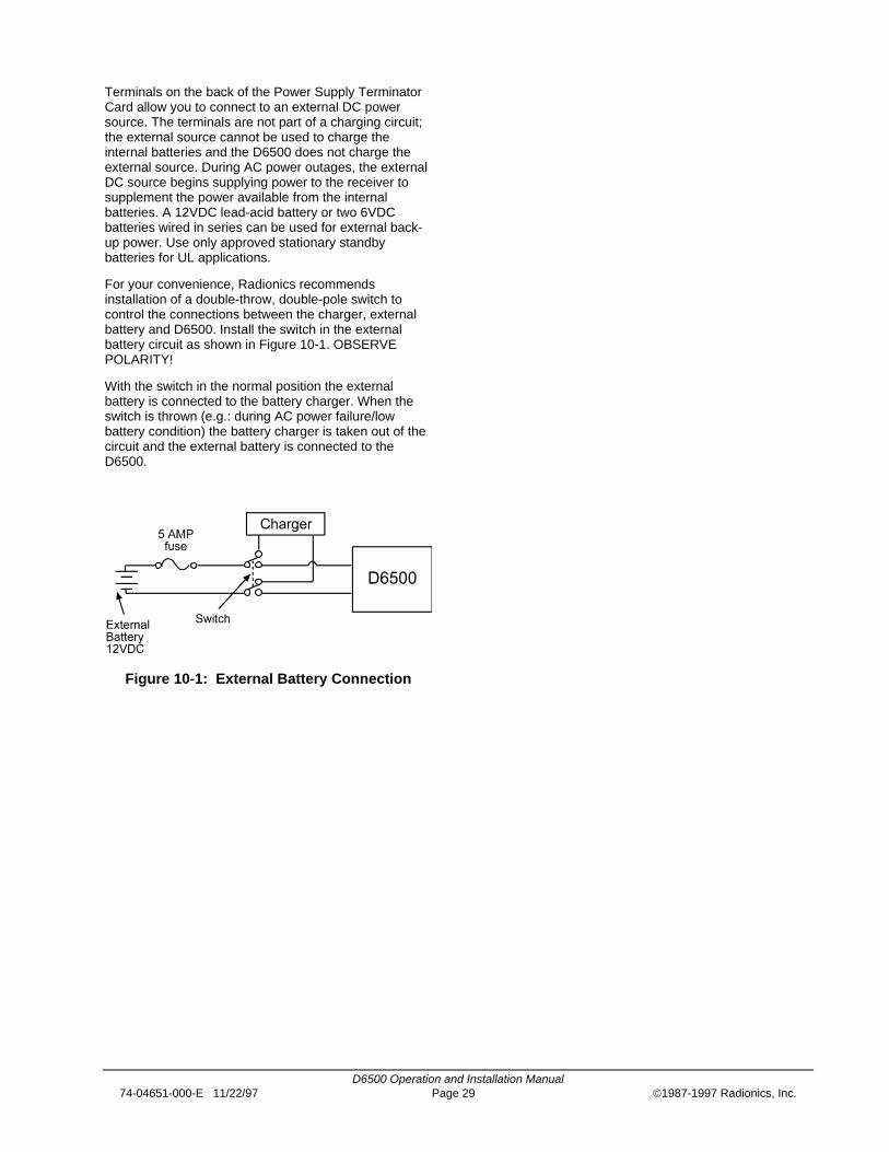
For your convenience, Radionics recommendsinstallation of a double-throw, double-pole switch tocontrol the connections between the charger, externalbattery and D6500. Install the switch in the externalbattery circuit as shown in Figure 10-1. OBSERVEPOLARITY!
With the switch in the normal position the externalbattery is connected to the battery charger. When theswitch is thrown (e.g.: during AC power failure/lowbattery condition) the battery charger is taken out of thecircuit and the external battery is connected to theD6500.
Figure 10-1: External Battery Connection
D6500 Operation and Installation Manual74-04651-000-E 11/22/97 Page 30 1987-1997 Radionics, Inc.
11. Clock and Calendar Controls
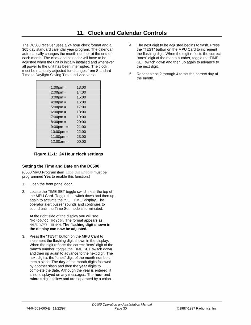
The D6500 receiver uses a 24 hour clock format and a365 day standard calendar year program. The calendarautomatically changes the month number at the end ofeach month. The clock and calendar will have to beadjusted when the unit is initially installed and wheneverall power to the unit has been interrupted. The clockmust be manually adjusted for changes from StandardTime to Daylight Saving Time and vice-versa.
1:00pm = 13:002:00pm = 14:003:00pm = 15:004:00pm = 16:005:00pm = 17:006:00pm = 18:007:00pm = 19:008:00pm = 20:009:00pm = 21:0010:00pm = 22:0011:00pm = 23:0012:00am = 00:00
Figure 11-1: 24 Hour clock settings
Setting the Time and Date on the D6500(6500:MPU Program item must beprogrammed Yes to enable this function.)
1. Open the front panel door.
2. Locate the TIME SET toggle switch near the top ofthe MPU Card. Toggle the switch down and then upagain to activate the “SET TIME” display. Theoperator alert buzzer sounds and continues tosound until the Time Set mode is terminated.
At the right side of the display you will see“00/00/00 00:00”. The format appears asMM/DD/YY HH:MM. The flashing digit shown inthe display can now be adjusted.
3. Press the “TEST” button on the MPU Card toincrement the flashing digit shown in the display.When the digit reflects the correct “tens” digit of themonth number, toggle the TIME SET switch downand then up again to advance to the next digit. Thenext digit is the “ones” digit of the month number,then a slash. The day of the month digits followedby another slash and then the year digits tocomplete the date. Although the year is entered, itis not displayed on any messages. The hour andminute digits follow and are separated by a colon.
4. The next digit to be adjusted begins to flash. Pressthe “TEST” button on the MPU Card to incrementthe flashing digit. When the digit reflects the correct“ones” digit of the month number, toggle the TIMESET switch down and then up again to advance tothe next digit.
5. Repeat steps 2 through 4 to set the correct day ofthe month.

D6500 Operation and Installation Manual74-04651-000-E 11/22/97 Page 31 1987-1997 Radionics, Inc.
12. Programming the D6500 Receiver
WARNING: The Programming Modeshould not be initiated while the receiver isoccupied with signal processing. TheD6500 display will show “RECEIVERBUSY:#” to indicate that a signal is beingprocessed, and the Line number (#)receiving the signal. Monitoring serviceshould be switched to a back-up receiverbefore attempting to edit the primaryreceivers program. After the ProgrammingMode is entered, the D6500 cannotanswer incoming calls. If an incoming callis detected, the line card RING indicatorwill light.
The D6500 Receiver is shipped with standard programsalready installed. The standard programs consist of thedefault settings shown in the D6500 Program EntryGuide. You can create customized programs using theD5200 Programmer. The programmer must be loadedwith the 6500:MPU and 6500:LINE Product HandlerPrograms. Descriptions of the program items are foundin the Program Entry Guides.
Many of the operational features of the D6500 can bealtered through programming options. The programmingoptions you choose will depend on the type(s) ofperipheral reporting device(s) used in your centralstation (e.g. external printer, auxiliary CRT orautomation computer), the supervision characteristicsfor these devices, the type of communicators reportingto the receiver, and the number and type of receivinglines in use.
12.1 Loading Customized Programsinto the Receiver
1. Create appropriate 6500:MPU and 6500:LINEprograms for your D6500 receiver. Name and saveeach of the files in the D5200 programmer.
2. Open the receiver’s display door and locate theMPU Card (see Figure 4-2).
3. Plug the D5200’s data/power cord into theProgrammer Jack located on the MPU Card (seeFigure 6-1).
4. Advance the D5200’s cursor to the handler ,and press the ENTER GROUP button.
5. Simultaneously press the SLNC and TEST buttonson the front of the D6500. The D6500’s displayshows the message: Prog: Programmer readywhen the receiver is ready to be loaded.
NOTE: If the display does not indicate“PROGRAMMER READY” within 20 secondsof pushing the TEST and SLNC buttons,the display momentarily shows
”Prog: CHECK PROGRAMMER”
and the Programming Mode is terminated. Makesure the programmer is plugged in properly andyou have entered the Product Handler, thenrepeat step 5.
6. Advance the programmer’s cursor to theappropriate program file name and press theENTER GROUP button. The first program itemappears in the programmer’s display.
7. Press the SEND (LOAD) button on theprogrammer. When loading a 6500:LINE program,you must enter the number of the line card you areprogramming, after you press the SEND (LOAD)button The D5200’s display shows: " Load to6500" momentarily then shows the first item of theprogram you have just loaded.
8. Press the EXIT GROUP button until appears in the programmer’s
display.
9. Unplug the programmer’s data/power cord.Approximately 20 seconds after the programmer isdisconnected, primary reporting devices will printmessages indicating the time the ProgrammingMode was initiated:
00/00 HH:MM PROGRAM MODE IN RCVR ##
and the time it was terminated:
00/00 HH:MM PROGRAM MODE OUT RCVR ##
NOTE: Simultaneously pressing the SLNC andTEST buttons also terminates theprogramming session. The programmercord can be unplugged before or afterterminating the session in this manner.
12.2 Editing Programs
When you are ready to re-program the D6500 to changethe operating parameters or add new features to yourreceiving system, you only need to edit the file affectedby the changes.
ALWAYS NAME AND SAVE the new program files inthe D5200 Programmer so that in the event that theprograms must be re-loaded into the receiver the mostcurrent programs will be readily available.

D6500 Operation and Installation Manual74-04651-000-E 11/22/97 Page 32 1987-1997 Radionics, Inc.
13. Program Default Initialization Routine
The Program Default Initialization Routine clears allmemory buffers and customized 6500:MPU and6500:LINE programs from the D6500 Receiver. Whenthis routine is initiated, all of the receiver’s programsreturn to the original default settings as shipped from thefactory. The time and date must be set and the customMPU and LINE programs must be reloaded after thisroutine is completed. To initiate this routine:
1. Put the DC slide switches in the OFF (down)position, then put the AC slide switches in the OFF(down) position.
2. Put the TIME SET toggle switch in the time-set(down) position.
3. Simultaneously put the AC and DC slide switches inthe ON (up) position.
4. Return the TIME SET toggle switch to the normal(up) position.
5. After the Cards have been given enough time toinitialize, set the time and date (see Section 11).

D6500 Operation and Installation Manual74-04651-000-E 11/22/97 Page 33 1987-1997 Radionics, Inc.
14. D6500 Operation
14.1 How Messages are Transmitted
Digital Communicators: Digital Communicators (alsoknown as digital dialers) use the switched telephonenetwork to transmit alarm and supervisory signals fromone location (protected premises) to another location(central station). Digital communicators use the sametelephone network as ordinary dial or Touch-Tone™(DTMF) telephones. This signal path can be within onebuilding (proprietary system) or across the nation.Digital communicators can be used anywhere you candial direct to the receiver without an operator’sassistance.
FCC Regulations: Digital communicators must beregistered with the Federal CommunicationsCommission and an approved coupler must be used toconnect it to the switched telephone network (per FCCregulations Part 68). It is a violation of FCC regulationsto connect a communicator to a pay phone or party line.Radionics’ communicators are registered with the FCCand use an RJ31X or an RJ38X jack for connection tothe telephone network. (An RJ31X jack provides lineseizure capability. An RJ38X provides both line seizureand telephone cord supervision capability.) The D6500Security Receiver is also registered with the FCC anduses an RJ11C jack for connection to the telephoneline.
Line Seizure: When the communicator changes state(e.g. from normal to alarm, trouble to normal, etc.), itgoes “off-hook” and seizes the telephone line. When theRJ31X (or RJ38X) is properly wired, “line seizure”prevents anyone from using the telephone when thecommunicator has a message to transmit. If someoneis using the telephone when the communicator seizesthe line, the original conversation is disconnected if thejack is properly wired. The communicator places a 600ohm load across the line’s tip and ring to initiate dialtone. After detecting the dial tone the communicatordials the central station receiver’s telephone number.(Some telephone lines require a momentary short toground to initiate dial tone. These are called “groundstart” systems. The communicator may requireadditional equipment or programming to initiate dial toneon a ground start system.)
Receiver Acknowledgment: A line card in the D6500Security Receiver is connected to the telephone linedialed by the communicator. The line card detectsringing voltage, answers the incoming call, and sends aprogrammed series of “acknowledgment” tones. If theacknowledgment tone expected by the communicator isnot transmitted by the receiver or not heard by thecommunicator, the communicator will not transmit itsmessage.
The acknowledgment tone is used for two purposes.These two purposes are commonly called “handshake”and “kiss-off”. The handshake is sent over the telephoneline when the D6500 answers the incoming line. Thehandshake tells the communicator that it has reachedthe central station and the receiver is ready to acceptdata. The kiss-off is transmitted by the receiver after thecommunicator’s message has been received andunderstood by the D6500. The acknowledgment tone’sfrequency is usually the same for both the handshakeand kiss-off (Radionics Modem II format Ack tone hasan inverted kiss-off).
Each line card installed in the D6500 receiver cantransmit 2300Hz, 1400Hz, Radionics Modem II,Radionics Modem IIe/IIIa2 and the Dual Toneacknowledgment tones. The receiver can beprogrammed for up to six acknowledgment attempts,using any combination of the available acknowledgmenttones. This allows communicators using different tonesto report to the same incoming line. The 6500:LINEProduct Handler program is used to select theacknowledgment tones and sequence in which they aretransmitted by each line card.
When the communicator hears the handshake tone, itsends an account code and the alarm zone information.The D6500 Receiver displays and prints messages byzone for communicators capable of transmitting theproper format. Radionics communicators can beprogrammed to transmit a variety of English languagemessages such as: TROUBLE, RESTORAL, OPENING,CLOSING, LISTEN-IN, and other supplementarymessages.
Message Verification: The D6500 receiver checkseach message for errors. Errors can be caused by anumber of factors including noise on the telephone lineor a malfunction in the communicator. If the data isreceived correctly, the receiver sends the kiss-offacknowledgment tone to the communicator. Thecommunicator then hangs up and returns thesubscriber’s telephone line to normal.
If the data is not correct, the receiver withholds the kiss-off tone and prints an “ERROR” message (see Section19. Error Reports), causing the communicator toretransmit the information. If the data is still not receivedcorrectly the communicator hangs up (Radionicscommunicators will usually try four times before hangingup). The communicator will then restart the signalprocess and attempt to retransmit another message.The communicator will repeat this process until thesignal acknowledgment tone is received or until thenumber of dialing attempts has been depleted.

D6500 Operation and Installation Manual74-04651-000-E 11/22/97 Page 34 1987-1997 Radionics, Inc.
Acknowledgment Tone Compatibility: When theD6500 Receiver answers an incoming line, it waits for aprogrammed number of seconds before transmitting theacknowledgment tone(s). Radionics communicators willwait approximately 30 seconds for the properacknowledgment tone, however some other brands ofcommunicators will hang up immediately if an improperacknowledgment tone is heard, and others may have avery short acknowledgment wait time.
Radionics recommends that you programthe line card so that the first acknowledg-ment tone transmitted is compatible withexisting equipment which will not waitthrough a sequence of acknowledgmenttones.
14.2 How Messages are Received
When a Message is Received: The receiver canprocess messages from all eight phone linessimultaneously. Each message is held in a temporarymemory buffer while it is checked for accuracy oftransmission. The messages are printed and displayedone by one as the previous message is cleared from thedisplay.
Radionics Control/Communicators can transmit multiplemessages in the same phone call. The receiver may beprogrammed to print all multiple message transmissionsas a group, or print each message as soon as it isreceived. Refer to program item in theD6500 Program Entry Guide for more information.
As each message is checked and determined to beaccurate, the D6500 sends the kiss-off acknowledgmenttone so the communicator can hang up, thus allowingthe receiver to process new incoming calls on the line.As reporting devices (e.g. printer, auxiliary CRT)become available to receive additional signals, theD6500 retrieves the stored messages from memorythen outputs the messages to the reporting devices.
How Call Groups Work: Programming in the6500:MPU Product handler allows each line card in theD6500 receiver to report and print as a part of a callgroup. Lines which operate in rotary are typicallyassigned to the same call group. A call group caninclude any combination of incoming lines, regardless ofthe physical location of the line card in the receiver, orthe geographical location of the accounts which reportto the various lines in the group. When a line isassigned to a call group, all reports on that line (with theexception of phone line or line card trouble reports) areidentified by the group number (e.g.: G1). If the line isnot assigned to a group, all reports are identified by theline card number (e.g.: L1) (see Section 17, BusySeconds, for further details on call groups).
Buzzer Operation: In the Manual Mode an OperatorAlert Buzzer sounds and an auxiliary relay closes whena message is received. The buzzer sounds and therelay remains closed until you press the SLNC button(the buzzer operation is programmable and can bedisabled when the receiver is programmed for theAutomatic Mode).
The auxiliary relay can be used to activate a remotebuzzer or a similar device. The output terminals for theauxiliary relay are located on the Power SupplyTerminator Card (see Figure 7-2). The relay is rated at 2amps (24VAC/DC) and is dry contact; it does notprovide power for the auxiliary device.
Reporting Devices, Primary and Secondary: Areporting device is any device which can print or displaymessages from the D6500 receiver. This includes theD6550 Printer (internal printer), a central stationautomation computer, external printer or auxiliary CRTconnected to the D6555 port. Program items in the6500:MPU program enable the internal printer, externalprinter, and automation computer and designate themas primary or secondary devices. Primary ReportingDevices receive all reports generated by the D6500.Secondary Reporting Devices only receive input fromthe D6500 when all primary devices fail.
If the receiver is in the Automatic Mode and ALL of theprimary reporting devices fail the receiver re-routes themessages to the secondary reporting device(s). If nosecondary reporting devices are programmed, or if allsecondary reporting devices fail, the D6500 willautomatically switch to Manual Mode. When a primarydevice is restored to normal operation, the D6500 goesback into the Automatic Mode, provided that the lastbuffered signal was manually acknowledged (refer toSection 16, Receiving Signals at the D6500).

D6500 Operation and Installation Manual74-04651-000-E 11/22/97 Page 35 1987-1997 Radionics, Inc.
15. D6500 Standard 40-Character Reporting Format
When the printer in the D6500 is a primary reportingdevice (see the D6500 Program Entry Guide) it recordsall incoming signal activity as well as severalsupervisory and diagnostic messages regarding thereceiver’s operation. As the printer records activity, theelectro-conductive paper tape (part number D6007)scrolls out of the printer. The most recent messages
appear at the top of the tape as it comes out of theprinter.
The D6500's LCD display , the D6500 Internal PrinterModule and any external devices connected to the CRTRS-232 Port of the Printer Terminator Card, all use thesame standard 40-character format.
11/2911/2911/2911/2911/2911/2911/2911/2911/29 1 5 : 3 2 1 5 : 3 2 1 5 : 3 2 1 5 : 3 2 1 5 : 3 2 1 5 : 3 2 1 5 : 3 2 1 5 : 3 2 1 5 : 3 2 B 3 B 3 B 3 B 3 B 3 B 3 B 3 B 3 B 3 A C C T 4 8 5 A L A RA C C T 4 8 5 A L A RA C C T 4 8 5 A L A RA C C T 4 8 5 A L A RA C C T 4 8 5 A L A RA C C T 4 8 5 A L A RA C C T 4 8 5 A L A RA C C T 4 8 5 A L A RA C C T 4 8 5 A L A R M R E P O R TM R E P O R TM R E P O R TM R E P O R TM R E P O R TM R E P O R TM R E P O R TM R E P O R TM R E P O R T11/2911/2911/2911/2911/2911/2911/2911/2911/29 1 5 : 3 4 1 5 : 3 4 1 5 : 3 4 1 5 : 3 4 1 5 : 3 4 1 5 : 3 4 1 5 : 3 4 1 5 : 3 4 1 5 : 3 4 L 3 L 3 L 3 L 3 L 3 L 3 L 3 L 3 L 3 A C C T 6 4 2 A C C T 6 4 2 A C C T 6 4 2 A C C T 6 4 2 A C C T 6 4 2 A C C T 6 4 2 A C C T 6 4 2 A C C T 6 4 2 A C C T 6 4 2 R E S T O R A L Z N 4R E S T O R A L Z N 4R E S T O R A L Z N 4R E S T O R A L Z N 4R E S T O R A L Z N 4R E S T O R A L Z N 4R E S T O R A L Z N 4R E S T O R A L Z N 4R E S T O R A L Z N 411/2911/2911/2911/2911/2911/2911/2911/2911/29 1 5 : 4 1 1 5 : 4 1 1 5 : 4 1 1 5 : 4 1 1 5 : 4 1 1 5 : 4 1 1 5 : 4 1 1 5 : 4 1 1 5 : 4 1 M 3 M 3 M 3 M 3 M 3 M 3 M 3 M 3 M 3 A C C T 1 5 2 3 A L A RA C C T 1 5 2 3 A L A RA C C T 1 5 2 3 A L A RA C C T 1 5 2 3 A L A RA C C T 1 5 2 3 A L A RA C C T 1 5 2 3 A L A RA C C T 1 5 2 3 A L A RA C C T 1 5 2 3 A L A RA C C T 1 5 2 3 A L A R M Z NM Z NM Z NM Z NM Z NM Z NM Z NM Z NM Z N 1 0 0 1 0 0 1 0 0 1 0 0 1 0 0 1 0 0 1 0 0 1 0 0 1 0 011/2911/2911/2911/2911/2911/2911/2911/2911/29 1 5 : 4 4 1 5 : 4 4 1 5 : 4 4 1 5 : 4 4 1 5 : 4 4 1 5 : 4 4 1 5 : 4 4 1 5 : 4 4 1 5 : 4 4 G 3 G 3 G 3 G 3 G 3 G 3 G 3 G 3 G 3 A C C T 3 8 7 4 C L O S I N GA C C T 3 8 7 4 C L O S I N GA C C T 3 8 7 4 C L O S I N GA C C T 3 8 7 4 C L O S I N GA C C T 3 8 7 4 C L O S I N GA C C T 3 8 7 4 C L O S I N GA C C T 3 8 7 4 C L O S I N GA C C T 3 8 7 4 C L O S I N GA C C T 3 8 7 4 C L O S I N G I D I D I D I D I D I D I D I D I D B 0 2 B 0 2 B 0 2 B 0 2 B 0 2 B 0 2 B 0 2 B 0 2 B 0 2
Figure 15-1: Single line 40-character message format
11/2911/2911/2911/2911/2911/2911/2911/2911/29 1 5 : 3 2 1 5 : 3 2 1 5 : 3 2 1 5 : 3 2 1 5 : 3 2 1 5 : 3 2 1 5 : 3 2 1 5 : 3 2 1 5 : 3 2 M 3 M 3 M 3 M 3 M 3 M 3 M 3 M 3 M 3 A C C T 4 8 5 A C C T 4 8 5 A C C T 4 8 5 A C C T 4 8 5 A C C T 4 8 5 A C C T 4 8 5 A C C T 4 8 5 A C C T 4 8 5 A C C T 4 8 5 A L A R M R E P O R TA L A R M R E P O R TA L A R M R E P O R TA L A R M R E P O R TA L A R M R E P O R TA L A R M R E P O R TA L A R M R E P O R TA L A R M R E P O R TA L A R M R E P O R T+++ +++ +++ +++ +++ +++ +++ +++ +++ A C C TA C C TA C C TA C C TA C C TA C C TA C C TA C C TA C C T 4 8 5 4 8 5 4 8 5 4 8 5 4 8 5 4 8 5 4 8 5 4 8 5 4 8 5 A R E A = 4A R E A = 4A R E A = 4A R E A = 4A R E A = 4A R E A = 4A R E A = 4A R E A = 4A R E A = 4 P O I N T = 2 8 4P O I N T = 2 8 4P O I N T = 2 8 4P O I N T = 2 8 4P O I N T = 2 8 4P O I N T = 2 8 4P O I N T = 2 8 4P O I N T = 2 8 4P O I N T = 2 8 4
Figure 15-2: Double line 40-character message format
15.1 Interpretation of Reports
Reports output by the D6500 are presented in astandardized 40-character x 2 line format. The secondline of the display is used only for receiver diagnostics,idle displays, and Modem II messages. This formatoffers a consistent arrangement of account reports, aswell as D6500 diagnostic messages. Two formats areavailable: the Single Line format and the Double Lineformat (see Figures 15-1 and 15-2). The Single Lineformat is the standard format for messages received inpulse, BFSK, and Modem II transmission formats. TheDouble Line format is used for D7112 and D9112Modem II message formats. Modem IIe/IIIa2 format
messages use additional lines for messages containingtext.
Single and Double Line FormatsDATE (1 thru 5): Displayed in a MM/DD format.
TIME (7 thru 11): Displayed in a HH/MM format.

D6500 Operation and Installation Manual74-04651-000-E 11/22/97 Page 36 1987-1997 Radionics, Inc.
FORMAT (13 thru 14): Identifies the Line or GroupNumber. If the Line is not programmed to report as partof a "Group", position 13 can identify the TransmissionFormat (L = Pulse, B = BFSK, M = Modem II). D6500internal reports appear with an "L". If the Line is part ofa "Group", a "G" appears in position 13 (see the 6500Program Entry Guide). Position 14 shows the line cardnumber or Group number receiving the report.
ACCOUNT IDENTIFICATION (16 thru 25): Shows theControl/Communicator's account identification number.Pulse (3x1 and 3x2*) and BFSK formats can reportaccount numbers containing up to three characters(positions 22 thru 24). Pulse (4x1 and 4x2*) andRadionics Modem II formats can report accountnumbers containing up to four characters (positions 21thru 24). Radionics Modem IIIa2 formats can reportaccount numbers containing up to ten characters(positions 16 thru 25) See Figure 15-3 for a comparisonbetween formats.
Single Line FormatTYPE OF EVENT (26 thru 33): Shows the type ofevent (Alarm, Restoral, Opening, Closing, Error, etc.)that triggered the report.
ZONE (35 thru 40): Displays the zone on which theevent occurred. Refer to Figure 14-2 for a comparisonbetween formats.
Pulse and BFSK: Positions 35 and 36 always shows"ZN". Pulse (3x1 and 4x1*) and BFSK formats canreport only single character zone identification, usingposition 40. Pulse (3x2 and 4x2*) formats can report upto two characters using positions 39 and 40.
Modem II: Positions 35 and 36 may show "ID" insteadof "ZN". "ID" is used to identify combinations used toarm and disarm a D8112, D6112 or D4112 systemprogrammed for opening/closing reports. Position 40 willonly be used if it is communicating an opening orclosing with a combination beginning with "9", if it issending a Restoral or Trouble ZN 9, a Duress, or astatus report. In all other cases Modem II will alwaysuse positions 38 thru 40 for any other zone, point, orcombination being communicated.
Double Line FormatTYPE OF EVENT (26 thru 40): Shows the type ofevent (Alarm, Restoral, Opening, Closing, Error, etc.)that triggered the report.
Line 2:+++ (1 thru 3): Identifies the second line as acontinuation of the previous line.
ACCOUNT IDENTIFICATION (5 thru 14): Shows theControl/Communicator's account identification number.Account numbers containing up to ten characters(positions 5 thru 14) can be reported.
ADDITIONAL EVENT INFORMATION (25 thru 40):Shows the expanded information provided by ModemIId, Modem IIe, and Modem IIIa2 formats. This mayinclude the "Area" number, "Point" number, "RF Point"number, "User" ID, "Operator" ID, "Relay" number,"Sked" number, "Phone #", "Phone Line" number, "SDI"number, and "Time". See the D6500 Report Directory(P/N 74-04651-001) for a complete listing of the signalswhich can be received in Modem II formats.
FORMAT NUMBER OF DIGITS ID ZNAccount Area Zone/
PointPulse 3x1 3 1 X
3x2 3 2 X4x1 4 1 X4x2 4 2 X
BFSK up to 3 1 XModem II up to 4 3 X XModem II(for D9112 and
D7112)
up to 4 1 3 X X
Figure 15-3: Format comparison chart
15.2 Message ExamplesBelow are some examples of messages that may bereceived at the D6500. A more complete directory ofreports is found in the D6500 Computer InterfaceManual (P/N 74-05313-000) and in the D6500 ReportDirectory (P/N 74-04651-001).
The following are examples of special reports whichhave a multiple line format.
Status reports print as follows (not used forPulse):
BFSK Example:
10/13 18:31 B1 ACCT 105 STATUS REPORT
10/13 18:31 B1 ACCT 105 RESTORAL ZN 2
10/13 18:30 B1 ACCT 234 STATUS REPORT
10/13 18:30 B1 ACCT 234 RESTORAL ZN 1
Modem II Single Line Example:
10/13 18:31 M1 ACCT B123 STATUS REPORT
10/13 18:31 M1 ACCT B123 RESTORAL ZN 2
10/13 18:30 M1 ACCT 6677 STATUS REPORT
10/13 18:30 M1 ACCT 6677 RESTORAL ZN 1
Modem II Double Line Example:
10/13 18:31 M1 ACCT 5687 S: TROUBLE
+++ ACCT 5687 AREA=1 POINT=123
10/13 18:30 M1 ACCT C167 S: TROUBLE
+++ ACCT C167 AREA=4 POINT=102

D6500 Operation and Installation Manual74-04651-000-E 11/22/97 Page 37 1987-1997 Radionics, Inc.
Signals transmitted during an AC Failure at theprotected premises print as follows (not usedfor Pulse):
BFSK Example:10/13 18:32 B1 ACCT 105 AC FAILED10/13 18:32 B1 ACCT 105 RESTORAL ZN 8
10/13 18:31 B1 ACCT 105 AC FAILED10/13 18:31 B1 ACCT 105 RESTORAL ZN 7
Modem II Single Line Example:10/13 18:32 M1 ACCT B123 AC FAILED10/13 18:32 M1 ACCT B123 RESTORAL ZN 801
10/13 18:31 M1 ACCT B123 AC FAILED10/13 18:31 M1 ACCT B123 RESTORAL ZN 700
Modem II Double Line Example:10/13 18:32 M1 ACCT 5687 AC FAILURE10/13 18:32 M1 ACCT 5687 RESTORAL REPORT+++ ACCT 5687 AREA=2 POINT=006
10/13 18:31 M1 ACCT C167 AC FAILURE10/13 18:31 M1 ACCT C167 RESTORAL REPORT+++ ACCT C167 AREA=3 POINT=010
Force Arming reports print as follows:
BFSK Example:10/13 18:33 B1 ACCT 105 WAS FORCE ARMED10/13 18:33 B1 ACCT 105 CLOSING ZN 810/13 18:32 B1 ACCT 105 TROUBLE ZN 7
Modem II Single Line Example:10/13 18:33 M1 ACCT B123 WAS FORCE ARMED10/13 18:33 M1 ACCT B123 CLOSING ID 80110/13 18:32 M1 ACCT B123 SHUNTED ZN 700
Pulse (4x2) Example:10/13 18:33 L1 ACCT 1243 ALARM ZN 8110/13 18:32 L1 ACCT 1243 ALARM ZN 72
Modem II Double Line Example:10/13 18:32 M1 ACCT 5687 WAS FORCE ARMED+++ ACCT 5687 AREA=1 ID=01310/13 18:32 M1 ACCT 5687 FORCED CLOSE
10/13 18:31 M1 ACCT C167 WAS FORCE ARMED+++ ACCT C167 AREA=1 POINT=03010/13 18:31 M1 ACCT C167 FORCED POINT
The following reports are shown as they would appearon the printer tape (oldest signal on the bottom, mostrecent signal on the top), followed by a brief explanationof each report.
11/22 13:45 L1 PHONE RESTORED RCVR 05
On November 22 at 1345 hours (1:45 PM) the tele-phone line connected to Line 1 was back in service.(Internal diagnostic.)
11/22 13:02 L1 PHONE TROUBLED RCVR 05
On November 22 at 1302 hours (1:02 PM) thetelephone connected to Line 1 went into troublecondition. This indicates an open or short on thetelephone line for more than 10 seconds.
11/22 12:03 L1 CARD RESTORED RCVR 05
On November 22 at 1203 hours (12:03 PM) the line cardor terminator card for Line 1 was back in service.
11/22 12:00 L1 CARD TROUBLED RCVR 05
On November 22 at 1200 hours (Noon) the line card orterminator card for Line 1 went into trouble condition.
11/22 10:00 L8 ACCT 888 [TEST] ZN 8
On November 22 at 1000 hours (10:00 AM) the TESTButton on the D6500 receiver was pressed to initiate aprinter test.
11/22 07:22 L2 ACCT 405 ALARM ZN 8
On November 22 at 0722 hours (7:22 AM) an alarmoccurred at account number 405, Zone 8. (Pulse 3x1format.)
11/22 03:29 B3 ACCT 117 TROUBLE ZN 9
On November 22 at 0329 hours (3:29 AM) accountnumber 117 went into low battery condition. (Thisindicates that AC power to the communicator wasinterrupted and the battery standby power is gettinglow.) The communicator was programmed forexpanded reporting. (BFSK format.)
11/21 22:39 M1 ACCT 240 CLOSING ID 3
On November 21 at 2239 hours (10:39 PM) accountnumber 240 armed the burglar alarm system with acombination beginning with 93. (Modem II format.)
11/21 20:22 L1 ACCT F33 RESTORAL REPORT
On November 21 at 2022 hours (8:22 PM) accountnumber F33 was restored following an alarm or troublecondition. The zone is unknown since the communicatorwas not programmed for expanded reports.
11/21 20:15 L1 ACCT F33 TROUBLE REPORT
On November 21 at 2015 hours (8:15 PM) accountnumber F33 reported a trouble condition. The zone introuble is not known since the communicator was notprogrammed for expanded reporting.
11/21 15:33 L1 ACCT 243 RESTORAL ZN 411/21 15:32 L1 ACCT 243 CANCEL REPORT
On November 21 at 1532 hours (3:32 PM) an alarmoccurred at account number 243. The subscriber turnedthe alarm off and closed the faulted loop (Zone 4) beforethe alarm was received at the central station. Theseprintouts could also be caused by a subscriber whoarrived at the premises after an alarm, disarmed thesystem and closed the faulted loop.

D6500 Operation and Installation Manual74-04651-000-E 11/22/97 Page 38 1987-1997 Radionics, Inc.
15.3 LCD Status Line Format
The 40-character LCD display line contains four fieldsof information (see Figure 15-4). Field 1 indicates the
system mode, field 2 contains the system message,field 3 indicates buffer usage, and field 4 indicates theListen-in status.
Auto: Auto: Auto: Auto: Auto: Auto: Auto: Auto: Auto: S y s t e mS y s t e mS y s t e mS y s t e mS y s t e mS y s t e mS y s t e mS y s t e mS y s t e m n o r m a ln o r m a ln o r m a ln o r m a ln o r m a ln o r m a ln o r m a ln o r m a ln o r m a l 8 2 %8 2 %8 2 %8 2 %8 2 %8 2 %8 2 %8 2 %8 2 % F u l l L /F u l l L /F u l l L /F u l l L /F u l l L /F u l l L /F u l l L /F u l l L /F u l l L / I : nI : nI : nI : nI : nI : nI : nI : nI : n
Figure 15-4: LCD 40-character display format
System Mode (1 thru 5)The following System Modes can be displayed:
Auto: indicates that the system is in automatic mode.
Manu: indicates that the system is in manual mode.
Prog: indicates that the system is in program mode.
Init: indicates that the system is booting up.
System Messages (7 thru 24)Three types of system messages can be displayed:Scrolling, Programmer, and System Test. If all selecteddevices are normal and the battery is not low, the"System normal" message is displayed (see Figure 15-4).
If multiple scrolling messages are applicable, eachmessage is displayed for a 3 second interval. When thesystem is in Programming (Prog:) mode, theProgrammer system messages take precedence overScrolling system messages. Test messages also takeprecedence over Scrolling system messages.
Scrolling System Messages:
Check internal prtCheck external prtCheck automationLow battery
Programmer System Messages:
Check programmerDownload failedCopy to 6500Copy from 6500Programmer readyProgramming doneReceiver busy:n
Buffer Usage (26 thru 34)The message buffer can hold up to 500 messages. TheBuffer Usage field indicates 100% Full when 436messages exist. After 436 messages are in the buffer,line cards can accept one additional message, and onlyinternal messages are allowed to enter the buffer. Whenthe message number is reduced to 415 messages(Buffer Usage = 94% Full), the line cards will again beable to accept phone messages.
Listen-In (36 thru 40)This field indicates on which card Listen-in is active(L/I:n), and the number of the line card connected tothe speaker.
D6500 Operation and Installation Manual74-04651-000-E 11/22/97 Page 39 1987-1997 Radionics, Inc.
16. Receiving Signals at the D6500
16.1 Operation in Manual Mode
The D6500 is programmed for Manual Mode using the6500:MPU Product Handler Program.
NOTE: The Manual Mode is not suitable for monitoringburglar and fire alarm accounts in a UL listedCentral Station. The D6500 receiver must beprogrammed for the Automatic Mode to complywith UL, FM, and NFPA standards for alarmmonitoring.
Receiving SignalsWhen signals are received while operating in themanual mode:
1. Reporting devices are activated and the OperatorAlert Buzzer sounds. Push the SLNC button to shutoff the Operator Alert Buzzer. Compare the displayto the printout to make certain you have correctlyread the data.
2. Push the SLNC button again. If there are noadditional messages the second push of the SLNCbutton clears the display. If there are additionalmessages the second push of the SLNC buttonallows the receiver to display and print the nextmessage.
3. Repeat the procedure until all outstandingmessages are recorded on the reporting device(s)and the display is clear. You must push the SLNCbutton to clear the display after each message andpermit the D6500 to display additional messages. Ifa message is not cleared the Operator Alert buzzerwill sound within approximately 40 seconds.
Typical Alarm Receiving Sequence in ManualMode1. An alarm occurs on Zone 3 at subscriber location
456. Account 456 is programmed to report to Line 1and Line 1 is not programmed to report to a callgroup.
2. The RING indicator on the D6500 receiver comeson at the Line 1 position.
3. The OL (On-Line) LED lights when the receiveranswers the call and the LED flickers as data isreceived.
4. The Operator Alert Buzzer sounds.
5. The D6500 LCD displays the alarm message in thestandard 40 character format.
6. The primary reporting device(s) (e.g. internalprinter, external printer, or automation computer) isactivated. If the internal printer is a primaryreporting device and the message is in Pulse orBFSK format, it prints the following message (BFSKformat is displayed with "B1" instead of "L1"):
11/11 14:10 L1 ACCT 456 ALARM ZN 3
If the message is in a Modem format, thereceiver’s internal printer prints the following:
11/11 14:10 M1 ACCT 456 ALARM ZN 300
7. Operator pushes the SLNC button to silence theOperator Alert Buzzer.
8. Operator compares the display to the printout foraccuracy.
9. Operator pushes the SLNC button again, clearingthe display panel. (If the SLNC button is not pushedthis second time the Operator Alert Buzzer willsound to remind you to clear the display.)
10. The receiver is now ready to display any additionalmessages.
16.2 Operation in Automatic Mode
The D6500 is programmed for Automatic Mode usingthe 6500:MPU Product Handler Program.
Operating the D6500 receiver in the Automatic Modemeets Underwriters’ Laboratories (UL), Factory Mutual(FM) and National Fire Protection Association (NFPA)standards for burglar and fire alarm monitoring. If youare using the D6500 receiver to monitor any fire alarmaccounts, you must operate the receiver in theAutomatic Mode. This also applies when connected to acentral station automation computer.
In the Automatic Mode the D6500 receiver sendsmessages immediately or in blocks to reporting devices(e.g.: printers, computers) as soon as the devices areready to receive the information (see program item
in the D6500 Program Entry Guide ). Signalsdo not remain visible in the display. The display iscleared and made ready to receive other signalsimmediately after the message is recorded on thereporting device(s). In the event that all reportingdevices fail, the D6500 reverts to the Manual Mode ofoperation until a device is returned to service (refer tothe Computer Interface Installation Manual). The D6500is normally programmed to sound the Operator AlertBuzzer while messages are being printed.

D6500 Operation and Installation Manual74-04651-000-E 11/22/97 Page 40 1987-1997 Radionics, Inc.
Typical Alarm Receiving Sequence inAutomatic Mode1. An alarm occurs on Zone 3 at subscriber location
456. Account 456 is programmed to report to Line 1and Line 1 is not programmed to report to a callgroup.
2. The RING indicator on the D6500 receiver comeson at the Line 1 position.
3. The OL (On-Line) LED lights when the receiveranswers the call and the LED flickers as data isreceived.
4. The Operator Alert Buzzer sounds (if 6500:MPUprogram item is programmed Yes,AND if either the internal printer or external printeris programmed as a primary device).
5. The alarm data momentarily appears on theReceiver’s LCD Display.
6. The primary reporting device(s) (e.g.; internalprinter, automation computer) is activated. If theinternal printer is a primary reporting device and themessage is in Pulse or BFSK format, it prints thefollowing message (BFSK format is displayed with"B1" instead of "L1"):
11/11 14:10 L1 ACCT 456 ALARM ZN 3
If the message is in a Modem format, the receiver’sinternal printer prints the following:
11/11 14:10 M1 ACCT 456 ALARM ZN 300

D6500 Operation and Installation Manual74-04651-000-E 11/22/97 Page 41 1987-1997 Radionics, Inc.
17. Busy Seconds (Line Busy) Reports
The D6500 receiver software monitors and reports thetime that a “call group” of receiver lines is unable toreceive signals. The receiver cannot process signals ifits incoming phone lines are in trouble, if othercommunicators have the line tied up, or if the line card isinoperative. The receiver interprets these conditions as“busy time.”
Busy Seconds Reports are based on the amount ofbusy time accumulated during a ten minute period. Theten minute busy time period begins when all lines in acall group become busy (or when a single line which isnot programmed for a call group becomes busy). TheD6500 totals the accumulated busy time and prints theBusy Seconds report after the ten minute period is over.A minimum accumulation of 60 seconds (10%) of busytime is required before a report is generated. The D6500will report up to a maximum of 100% busy time.
If Busy Seconds reports are not wanted, it is possible todisable them by programming item ,in the MPU program, No. This function is not selectableby line card. Busy Seconds must be Yes for UL listedCentral Stations.
Underwriters’ Laboratories inspectors may investigatethe amount of time that the digital receiver lines areunable to receive signals. It is very important to ensurethat lines are available to process emergency signals ona timely basis. Excessive line busy reports may indicatethat it is necessary to install additional lines in rotarywith your primary receiver lines.
Each line card can be assigned to a call group throughprogram entries in the 6500:MPU Product Handlerprogram. A line card can be assigned to group numbers1 through 8. For the group to start accumulating busytime, all lines in the call group must either be on-line, introuble or without an operating line card. (Note:Although it is not mandatory, Radionics recommendsthat you assign lines to a call group. If a line is notassigned to a group, or if there is only one line in thegroup, one minute of busy time during a 10 minuteperiod will result in a Busy Seconds report.) If you donot assign a line to a call group, displays and printerreports identify the LINE number, instead of GROUPnumber. A line busy report is displayed and printed asfollows:
11/19 06:20 L1 BUSY SECONDS 23% RCVR 01

D6500 Operation and Installation Manual74-04651-000-E 11/22/97 Page 42 1987-1997 Radionics, Inc.
18. Listen-In
NOTE: This feature is not suitable for use on units usedfor monitoring UL Certified accounts since itmay delay the receipt of alarm signals.
The D6500 will decode the first digit of the accountnumber of the message to determine if Listen-In isrequired. The range of digits that will initiate Listen-In isselectable by line card. The range is programmed initems and of the line cardprogram. The amount of time the D6500 will listen-in isdetermined by line item in the line cardprogram.
When transmitting in BFSK or a Modem format, thelisten-in time is determined by the listen-in timeprogrammed in the panel.
The D6500 will accept additional information duringrefresh cycles. If the communicator has informationother than alarms it will be sent at refresh time. Ifanother alarm is generated, the communicator will hangup and call back to the central station.
When multiple Listen-In calls are received at the sametime, the operator can switch from line to line bypressing the Listen-In (LI) button on the front of the linecard. Only lines connected to the speaker can be madeto hang up. This is done by pressing the Listen-In (LI)button on the front of the line card one time. If a linecard is not connected to the speaker, one press of theListen-In button will connect that line to the speaker andthe next will cause that line to hang up.
During Listen-In, the current card number connected tothe speaker is displayed on the D6500 LCD display.

D6500 Operation and Installation Manual74-04651-000-E 11/22/97 Page 43 1987-1997 Radionics, Inc.
19. Error Reports
19.1 Description
If a message is garbled (incorrect checksum orinconsistent message rounds) due to a noisy phone lineor other difficulty, the receiver withholds theacknowledgment tone. This causes the communicator toretransmit the same message. Even if thecommunicator has more than one message to send, itdoes not attempt to transmit another message until itreceives the acknowledgment tone for the firstmessage. Radionics communicators will retransmit amessage up to four times. After four consecutive errormessages are received the receiver hangs up so thecommunicator can re-dial the receiver and possiblyestablish a better connection. Some error messagesmay cause the receiver to immediately hang up and re-initialize the line card. When this happens, the printerprints a report with the following format:
MM/DD HH:MM L# DIGITAL LC 06.00 RCVR ##
When you receive an error message, first try todetermine the location and type of signal so that youcan dispatch the proper response. Make a note of thetime, date, line number and the account number onwhich the error occurred. Any information that has an[ERROR] on the same line is probably incorrect.
Sometimes an Error Message contains one line of clearsignal enabling you to determine the actual location andtype of signal being transmitted. For example:
10/13 09:22 L1 ACCT 096 [ERROR] ZN 510/13 09:22 L1 ACCT B11 TROUBLE ZN 610/13 09:21 L1 ACCT F02 [ERROR] ZN 210/13 09:21 L1 ACCT F96 [ERROR] ZN 5
The D6500 displays and prints each message asreceived along with the word “[ ERROR ].” All of themessages transmitted in a single call can be printed asa group if 6500:MPU program item is setto Yes.
The receiver’s diagnostic routines analyze themessages to determine whether the message was sentvia BFSK, Modem, DTMF, or Pulse format. As atroubleshooting aid, the receiver prints supplementary“Pulse Error” reports when erroneous signals aretransmitted in Pulse format, or IF the line card receivingthe signal is programmed for expanded Pulse Errorreports in 6500:LINE program item . (For anexplanation of expanded Pulse Error Reports, seeSection 19.4).
When to Report Communication Trouble: If youreceive several error messages from a particularlocation, your supervisor and/or service personnelshould be notified to service that location. If you receiveerror messages from several accounts on one receiver
line, the problem could be the receiver’s line card or thetelephone line connected to the line card. You mayneed to report the trouble to the telephone company. Ifyou have a consistent problem with errors, it may benecessary to call Radionics Customer Service forassistance (see Section 2, Emergency Procedures).
19.2 BFSK Error Reports
Communicators programmed for BFSK transmissionuse a series of tones to transmit data. BFSKtransmissions can carry more data and transmit fasterthan Pulse transmissions. If an error message isreceived in BFSK, the receiver decodes the message asreceived, but does not print any alarm information orsupplementary reports. For example, the receiver wouldprint the following BFSK error messages as they werereceived in the same phone call:
10/13 09:29 B1 ACCT [ERROR] ZN10/13 09:29 B1 ACCT [ERROR] ZN10/13 09:28 B1 ACCT [ERROR] ZN
19.3 General Error Reports
General [ERROR] message can be for Pulse, BFSK, orModem formats. The transmission format is determinedby the character to the left of the line card number,before ACCT is printed. M is for Modem formats, B is forBFSK, and L is for Pulse or line card number.
19.4 Pulse Error Reports
Expanded Pulse Error reports are printed along with theGeneral Error Messages when they are enabled in6500:LINE program item . Pulsetransmissions use a single tone to carry thecommunicator’s message. The tone’s presence andabsence on the telephone line at pre-determinedintervals create digits which define the message (theoperation is similar to the pulses used to dial telephonenumbers with rotary dial telephones). Pulse Error reportinformation could be very valuable to field servicepersonnel as they troubleshoot communicationproblems.
When erroneous messages are received in Pulseformat, the D6500 can print supplementary messagesso that the probable cause of the error can bedetermined. The supplementary message is printedbefore the actual error message to identify the reportwhich follows as an error message. Each round of theerror message is printed as it was received. A Pulsetransmission containing errors could print as shown inFigure 19-1 (read lines from bottom to top, as theywould appear on the printer).

D6500 Operation and Installation Manual74-04651-000-E 11/22/97 Page 44 1987-1997 Radionics, Inc.
10/13 09:29 L2 ACCT 234 TROUBLE ZN 3 <-Message 6 This is a valid signal10/13 09:28 L2 ACCT BFF [ERROR] ZN 3 <-Message 5 Error Message10/13 09:28 L2 PULSE ERROR 3 40 RCVR 01 <-Message 4 Supplementary Message10/13 09:28 L2 ACCT FFF [ERROR] ZN <-Message 3 Error Message10/13 09:28 L2 PULSE ERROR 4 30 RCVR 01 <-Message 2 Supplementary Message10/13 09:27 L2 ACCT 234 TROUBLE REPORT <-Message 1 This is a valid signal
Figure 19-1: Pulse Error Reports
Message Interpretation (Figure 19-1):Message 1: When the communicator transmitted the
first message, no error was detected.
Message 2: While the second message was beingtransmitted a Pulse Error occurred. ThisPulse Error report identifies the followingerror message as a double-roundtransmission in which an incorrect numberof digits were received.
Message 3: This is the actual signal as received in thesecond round of the transmission.
Message 4: This Pulse Error report identifies thefollowing report (second round) as adouble-round transmission in which therounds did not match.
Message 5: This is the actual signal as received in thesecond round of the transmission.
Message 6: On this attempt at transmitting the secondmessage, no error was detected.
The digits following PULSE ERROR in the Supple-mentary Messages are used to identify the kind oftransmission error detected, the communicator zonewhich initiated the signal, and the “checksum digit.”These significant digits are identified as follows:
10/09 09:28 L2 PULSE ERROR 3 30 RCVR 01
Type of ErrorNumber of Digits ReceivedLast Digit Received
Type of Error:1 = Failed the Ratio Test. Too much variation in
the pulse lengths. Parameter may affect this condition.
2 = Single Round Checksum Error: The digits received did not equal the pre-determined checksum number.
3 = Double Round Comparison Error: The information received was not the same in both rounds.
4 = Double-round incorrect number or digits.
5 = Single-round incorrect number of digits.
Number of Digits Received:The number of digits received from the communicator inthe round.
Last Digit Received:A digit added to single-round transmissions which, whenadded to the other digits in the message equals anumber which is evenly divisible by 15. If the sum of allof the digits in the transmission is not evenly divisible by15, the message is reported as an error.
19.5 Modem II, IIe, IIIa2 Error Reports
Communicators programmed for Modem formats carrymore data in a phone call than Pulse or BFSKtransmissions. If an error message is received in aModem format, the receiver decodes the message asreceived, but does not print any supplementary reports.For example, the receiver could print the followingModem error messages as they were received in thesame phone call:
10/09 13:02 M1 ACCT 8112 (ERROR) ZN 10010/09 13:02 M1 ACCT 8112 (ERROR) ZN 10010/09 13:02 M1 ACCT 8112 (ERROR) ZN 10010/09 13:02 M1 ACCT 8112 (ERROR) ZN 100
19.6 Service Required Messages
A service required message is generated by thereceiver when one of the following conditions occurs:
1. A GSC Slave Dialer transmitting in single roundformat should be reprogrammed for double round.
2. The receiver received 10 or more pulses in a pulseformat transmission.
3. A D8112G1 control panel with setto Yes should be reprogrammed to No.

D6500 Operation and Installation Manual74-04651-000-E 11/22/97 Page 45 1987-1997 Radionics, Inc.
20. Troubleshooting Guide
The D6500 Receiver is made up of several plug-inassemblies which you can easily replace in the field.(Components and controls on individual assemblies areshown starting at Section 4.)
Do not attempt to repair individual assemblies. Anyfailed assemblies should be returned to Radionics fortesting and repair. This Trouble Shooting Guide can beused to assist in the identification of failed modularcomponents. Diagnostics are built into the D6500Receiver which monitor the status of the line cards,Power Supply, and Printer.
The D6500 can be programmed so that some featuresdo not function. Check the programs loaded into thereceiver to verify that the feature is enabled beforeassuming that a component has failed.
Individual Trouble Cases,Troubleshooting Procedures
AC Indicator is Flashing.AC power not available to the Receiver.
1. Check the AC switch on the Power Supply Card.Make sure it is in the “up” position (on).
2. Check 120-volt commercial AC power branchcircuit.
3. Check to see that the plug-in transformer issupplying between 17 and 19 volts AC.
4. Press the AC Circuit Breaker (CB1) reset button onthe Power Supply Terminator Card.
AC Indicator is Flashing and BAT Indicator isOn.AC power not available to the Receiver and the internalstandby batteries have discharged to 11.7VDC or less.
1. If the central station is not experiencing acommercial power failure, check AC powerconnections to the receiver as outlined above.
2. If the central station is experiencing a commercialpower failure, check the Battery switch on thePower Supply Card to make sure it is in the “up”position (on). Connect an external power supply tothe receiver.
BAT Indicator is On and AC Indicator is On.Internal standby batteries may be discharged eventhough AC power is connected.
Note: The BAT indicator stays lit after AC restores untilthe batteries are recharged to 13.2VDC. If theBAT indicator stays lit beyond normal rechargingtime:
1. Check the Battery switch on the Power Supply Cardto make sure it is in the “up” position (on).
2. Press the Circuit Breaker (CB3 and CB4) resetbuttons on the Power Supply Terminator Card.
3. Check all battery connections (e.g.: connector J3on Power Supply Terminator and BatteryTerminals).
4. Replace the D126 Batteries. If the BAT indicator isstill on, replace the Power Supply Terminator Card.
5. If the BAT indicator is still on, replace the PowerSupply Card.
Line Card TRBL, RING and OL Indicators ComeOn.If the line card is trying to boot but not communicatingwith the MPU the following may occur:
1. All three lights on the line card come on and stay onfor about four seconds.
2. The OL (On-Line) light is on for approximately 17seconds.
3. All three lights go back on for about four seconds
Verify that the line card is programmed to besupervised.
Line Card TRBL (Trouble) Indicator isIlluminated.Either the telephone line, the telephone connectingcord, line card, or Telco Terminator is defective.
1. Pull the line card out of the receiver, then re-insert itto insure the card is properly connected.
2. Swap the connecting cord with a phone line whichis not in trouble. If the original TRBL indicatorremains illuminated, the problem is with a plug-incard. Replace the line card with a spare. If theTRBL indicator on the new replacement card isilluminated, change the Line Terminator Card.

D6500 Operation and Installation Manual74-04651-000-E 11/22/97 Page 46 1987-1997 Radionics, Inc.
3. If the TRBL indicator on the original troubled cardgoes out and the TRBL indicator on the previouslyun-troubled card illuminates when you swapconnecting cords, the trouble is with either theconnecting cord or the telephone line. Replace thetelco line connecting cord.
4. If the TRBL indicator is still lit, the trouble may be inthe telephone line. Report the trouble to Telco.
NOTE: If a telephone line is out of order, and is the firstline in a rotary or hunt group, IMMEDIATEACTION IS NECESSARY! Have the telephonecompany busy the defective line at thetelephone exchange. If emergency service is notavailable, call the troubled line and leave thecalling handset off-hook. Do not hang up!Incoming alarm signals see a busy signal androtor (hunt) to another line in the hunt group.This procedure will not work for WATS (WideArea Telephone Service) Lines.
Clock and/or Calendar Cannot Be Set.The receiver may not be programmed for time set.
1. Check the 6500:MPU program item enabling timesetting.
2. Defective or loose cable between display panel andMPU Card.
3. Defective display panel.
4. Defective MPU Card.
Printer Works, But No Display.1. Defective or loose cable between MPU Card and
display panel.
2. Defective MPU Card or defective Power SupplyCard.
Operator Alert Buzzer Cannot Be Silenced.1. Push TEST Button for printer test. If printer is
inoperative you may be hearing the Printer Buzzerinstead of the Operator Alert Buzzer. Printer Buzzersounds when the Printer Circuit Card has no DCpower. Power-down the receiver and remove thePrinter Module. Press the circuit breaker resetbutton (CB1) on the Printer Module’s circuit board(see Figure 8-3).
2. Defective Silence Button. Replace the MPU Card.
Printer Inoperative, Display and Operator AlertBuzzer Work.1. Paper out of contact with Paper Sensor .
2. Printer Control Switch turned off.
3. Circuit breaker on Printer Module tripped. Power-down the receiver and remove the Printer Module.Press the circuit breaker reset button (CB1) on thePrinter Module’s circuit board (see Figure 8-2).
4. Defective Printer Module.
5. Defective MPU Card or Power Supply Card.
Caution: If it is ever necessary to return thePrinter Module to Radionics for repair, it MUSTbe packaged carefully. Excessive stress placedon the printer circuit board may cause hairlinefractures in the board, making it un-repairable.
Printer Buzzer Sounds But No Display (BuzzerCan Not Be Silenced)Printer Buzzer sounds when the Printer Circuit Card hasno DC power.
1. Power-down the receiver and remove the PrinterModule.
2. Press the Circuit Breaker Reset Button (CB1) onthe Printer Module’s circuit board (see Figure 8-2).
D6500 Operation and Installation Manual74-04651-000-E 11/22/97 Page 47 1987-1997 Radionics, Inc.
21. Using External Reporting Devices with the D6500
21.1 Central Station AutomationSystem Computer
A central station automation system computer can beconnected to the “COMP RS-232” port (AutomationComputer port) on the D6515 MPU Terminator Card(see Figure 6-2). The output from the automation port isconfigured by programming in the 6500:MPU producthandler program (see the D6500 Program Entry Guide).
RS-232 Jumper Configuration: Configuration jumperson the D6515 MPU Terminator Card are used to set thedata control lines for the automation computer RS-232port. For information on configuring the output from theD6500 see the D6500 Computer Interface InstallationManual (P/N 74-05313-000).
Caution: If you are not connecting anautomation computer to this port, LEAVETHESE JUMPERS IN THE STANDARDPOSITION AS SHIPPED. Certain jumperconfigurations could cause permanent damageto the RS-232 output and may also damageother components in the D6500.
21.2 Auxiliary CRT or Printer
Printer Terminator Card CRT RS-232 Connection:The port on the D6555 Printer Terminator Card providesa CRT or external printer output which matches theD6500 Internal Printer’s output. Reports from this outputare provided as formatted on the printer tape. Seesection 8.2 for jumper information. For baud rateprogramming, etc., see the D6500 Program EntryGuide.
D6500 Operation and Installation Manual74-04651-000-E 11/22/97 Page 48 1987-1997 Radionics, Inc.
22. Central Station Tips
BACKUP RECEIVER: Spare circuit boards and/orreceivers should be available at the centralstation. Radionics recommends that a spareD6550 Printer be kept on hand. UL listedcentral stations monitoring burglary or firealarms are required to have a redundantreceiver available which can be activatedwithin thirty (30) seconds.
Radionics does not support operation ofreceivers in parallel. Don’t have the spareequipment wired up, powered or in the sameequipment rack as the primary equipment. Thisminimizes catastrophic failures caused bydirect lightning strikes.
COMPUTER INTERFACE: Spare cards for all receivercomponents are strongly recommended. Aspare MPU Terminator Card with jumpersproperly configured should be kept in thecentral station.
D5200 REMOTE PROGRAMMER: Radionicsrecommends that you keep a D5200programmer loaded with the 6500:MPU and6500:LINE Product Handlers in the centralstation at all times.
PHONE LINES
Emergency Ringers: Extension ringers forincoming receiver phone lines are availablefrom telephone equipment supply companies.They ring very briefly to signify an incomingcall. If they continue to ring, that means yourreceiver is out of service. The ringer has avolume control but in a high traffic centralstation you might prefer to use beehive lightsinstead of ringers.
Rotary Lines: Rotary receiver lines (huntgroups) are strongly recommended to preventalarm signals from being delayed duringperiods of busy central station traffic. Rotarylines also are important to provide alternatepaths when a line is out of service. To use thisimportant feature your dispatcher should dialthe out-of-service line and leave the callingphone off the hook. This will busy out the lineto all incoming communicators and they willautomatically rotor to an unused line. Rotaryservice is provided at the Telco Central Officeand must be ordered.
Essential Service: Many phone companiesprovide a higher level of service for communityservices such as police, fire, or hospitalfacilities. During outages these essentialservices receive repair priority over regularcustomers. Check with the phone company tosee if your company qualifies for this importantbenefit.
Alternate Routes: In many service areas thetelephone company can supply a back-up lineor route your second line through differenttrunk routes than your first data line. This helpsprevent trunk problems from disabling yourcentral station. Check with the telephonecompany to see if this service is available inyour area.
WATS Lines: WATS (Wide Area TelephoneSystem) lines can provide a low cost method ofmonitoring long distance accounts. Howeversome WATS lines do not have voltage until asignal is actually ringing in; the Model D6500Receiver shows line trouble on these lines untila call is actually received. To prevent this,order WATS lines with “idle voltage”. If voltagelines are not available your D6500 can beprogrammed to not monitor line troubles.
Caution: UL and FM central station servicestandards require phone lines that areconstantly monitored.
PROPER GROUND: Receivers should be connected toearth ground, not chassis or electrical ground.Measure the resistance of the Receiver groundto another ground. If the meter reads above 2ohms, check your Receiver ground against athird ground. If the difference is still greaterthan 2 ohms, ground your Receiver to adifferent earth ground. Cold water pipes or agrounding rod usually make a good earthground. The grounding wire should be heavycopper with as short and straight a run aspossible. Avoid sharp bends in the ground wirebecause a large power surge might arc acrossthe bend.
The Terminator Cards and their connection tothe receiver cabinet provide the ground sourcefor the receiver’s circuit boards. The screwsused to secure the Terminator Cards to theback of the receiver cabinet must be firmlytightened at all times.

D6500 Operation and Installation Manual74-04651-000-E 11/22/97 Page 49 1987-1997 Radionics, Inc.
WARNING: If the mounting bracket screwsare not tight, the receiver’s operation could beerratic. The receiver could fail in the event of ashort circuit or if foreign voltage is induced intothe system.
Put an anti-static mat in front of the Receiver toprevent electro-static discharge from operatorto equipment.
RADIO FREQUENCY INTERFERENCE: The D6500Receiver is microprocessor based. Allmicroprocessors are susceptible to RFI (RadioFrequency Interference) especially at the 480MHz and 950 MHz bandwidths used by walkie-talkies. Never key a walkie-talkie in the vicinityof the Receiver.
TEST COMMUNICATOR: A digital communicatortriggered by an interval timer provides anexcellent periodic check on your receiver andits phone lines. If you have more than one dataline use a communicator for each line, or use amultiple number communicator.

D6500 Operation and Installation Manual74-04651-000-E 11/22/97 Page 50 1987-1997 Radionics, Inc.
23. Glossary
AC - Alternating Current
Acknowledgment Tone - A signal exchanged betweentransmitting and receiving equipment to indicatereadiness to communicate or that a clear transmissionhas been received.
Auxiliary Power - Additional direct current poweravailable from a communicator for powering protectivedevices such as smoke detectors.
BFSK - Binary Frequency Shift Keying (see FSK).
Battery - Source of stand-by DC power.
Cancel Report - A message sent to the central stationreceiver upon the disarming of a burglar alarm systemafter an alarm.
Card - A printed circuit board which is plugged into amain printed circuit assembly.
Central Office - The physical Telco location wheresubscriber phone lines are connected to the switchednetwork.
Central Station - The room, equipment and operationthat monitors alarms and dispatches the authorities.
Checksum - A method of checking accuracy oftransmitted information. A number representing the totalnumber of bits of information transmitted is included withthe transmission. The microprocessor counts the bits ofinformation received and compares its sum to thetransmitted checksum number. If the numbers do notmatch, the transmission is in error.
Closing Report - The arming of a burglar alarm systemand subsequent reporting to the central station.
Communicator - See Digital Communicator.
CRT - Cathode Ray Tube. The television displaymonitor used by a computer.
DC - Direct Current.
Dial Tone - A continuous signal (350 or 440 Hz)generated at the local telephone exchange to indicatethat the system is ready for dialing.
Decimal - A numbering system based on 10 possiblenumerical choices: 0, 1, 2, 3, 4, 5, 6, 7, 8, 9.
Digital Communicator - An electronic device used totransmit alarm signals from a subscriber to a centrallocation by using the existing phone network.
Digital Dialer - See Digital Communicator.
Direct Wire - A method of transmitting alarm signalsfrom one subscriber to a central receiving location byvarying voltage levels, current or current direction.
DTMF - Dual Tone Multi-Frequency. A signaling methodusing set pairs of specific frequencies (such as in TouchToneTM).
EPROM - Erasable Programmable Read Only Memory.A method of semi-permanently storing data in anintegrated circuit chip. EPROMs can be erased and newdata entered.
ESS - Electronic Switching System. A computercontrolled telephone exchange.
Expanded Report - A method of transmitting ALARM,TROUBLE and RESTORAL reports by zone.
Extension Ringer - A remote telephone bell.
FM - Factory Mutual System – A consortium of four verylarge insurance companies specializing in industrial andhighly protected risk (HPR) fire insurance. FM does notrecognize UL listings. All fire protection equipmentinstalled in FM insured risks must be FMRC approved.
Factory Mutual Research Corporation (FMRC) – Servesas a testing laboratory to evaluate and approve varioustypes of fire protection equipment and devices for use inFM insured properties.
Forced Arming - A method of overriding the safetyfeature which prevents arming with a faulted circuit on acommunicator.
FSK - Frequency Shift Keying. A form of frequencymodulation in which the modulating wave shifts theoutput frequency between predetermined values. This isa method of digital communication in which the twobinary states are represented by two differentfrequencies.
Ground - 1) A metallic connection with the earth toestablish earth ground potential. 2) The voltagereference points in a circuit.
Handshake Tone - A signal exchanged betweentransmitting and receiving equipment to indicatereadiness to communicate or that a clear transmissionhas been received.
Hexadecimal - A numbering system whose base is theequivalent of the decimal number sixteen.
The following decimal numbers:
0, 1, 2, 3, 4, 5, 6, 7, 8, 9, 10, 11, 12, 13, 14, and 15are represented by the characters:
0, 1, 2, 3, 4, 5, 6, 7, 8, 9, A, B, C, D, E, and F in Hexadecimal.

D6500 Operation and Installation Manual74-04651-000-E 11/22/97 Page 51 1987-1997 Radionics, Inc.
Interstate WATS - Wide Area TelecommunicationsSystems. Phone calls between different states in theUnited States using special phone lines. (WATS Linesare usually designated by an 800 Area Code. Chargesare automatically billed to the receiving party rather thanthe calling party.)
Intrastate WATS - Wide Area TelecommunicationsSystem. Phone calls within one state using specialphone lines. (WATS Lines are usually designated by an800 Area Code. Charges are automatically billed to thereceiving party rather than the calling party.)
Kiss-off - A tone sent from the Receiver to thetransmitter to indicate that transmitter’s message wasreceived. Once the transmitter “hears” the Kiss-off toneit returns the telephone line to the on-hook condition ifthere are no more messages to be sent.
LED - Light Emitting Diode
Line Seizure - The prevention of one or both sides of aphone line from reaching the phones on that line while adevice such as a communicator is using the line fortransmission.
Local Control - An alarm device that activates anaudible sounding device when it detects an alarmcondition.
MOV - Metal Oxide Varistor. A variable semi-conductorresistor. See Varistor.
Modem II, IIe, IIIa2 Format Communications - AControl/Communicator signaling format which transmitsat over twice the speed of BFSK communications. Theaccelerated transmission rate provides over twice thedata of BFSK communications. Modem Formats utilizesa unique Modem acknowledgment tone, password, andkiss-off tone.
Microprocessor - An integrated circuit chip capable ofperforming programmed instructions.
Off-hook - A Telco term to describe the condition whena phone is lifted off its cradle. This is equivalent toplacing 600 ohms across the two wires.
Opening Report - The disarming of a burglar alarmsystem and its subsequent reporting to the centralstation.
Program - A series of instructions for themicroprocessor.
PROM - Programmable Read Only Memory. A methodof permanently storing data in an integrated circuit chip.The data within the PROM cannot usually be changed.
Pulse Dialing - A method of selecting the callednumber by pulsing the phone line.
Restoral Report - A signal transmitted upon theremoval of a trouble or alarm condition from an alarmcircuit.
RF - Radio Frequency.
RFI - Radio Frequency Interference. Any electricalsignal of sufficient force induced by radio frequencysignals.
RJ11C - A Telco supplied connecting block used toattach customer provided equipment to Telco lines.
RJ31X - A Telco supplied connecting block used toattach customer provided equipment to Telco lines.Provisions are made for line seizure.
RJ33X - A Telco supplied connecting block used toattach customer provided equipment to Telco linesterminating in key equipment. Provisions are made forline seizure and lamp (A+A1) control.
RJ38X - Identical to RJ31X with addition of provision forTamper Circuit.
Rotary - A Telco term for a series of phone lines whichwill switch from the primary line to other lines if thecalled line is busy. Rotary service is provided at theTelephone Company Central Office.
Rotary Dialing - See Pulse Dialing.
RS232 - The EIA (Electronic Industries Association)standards for Serial Binary Data Interchange betweencomputers and their peripheral devices.
Short - An abnormal circuit condition in which a lowresistance path excess current flow.
Software - A program stored in semi-conductormemory.
Supervised Account - A burglar alarm system in whichthe arming and disarming of the alarm system isrecorded at a central station.
Supervised Circuit - An electrical circuit which detectscircuit malfunctions (opens, shorts or open/shorts) andreports them separately from alarms.
Telco - Abbreviation for Telephone Company.
Touch-ToneTM - A method of dialing the phone numberby transmitting dual tones (DTMF) instead of singlefrequency pulses. A registered trademark of AT&T.

D6500 Operation and Installation Manual74-04651-000-E 11/22/97 Page 52 1987-1997 Radionics, Inc.
U.L. - Underwriters Laboratories Inc., founded in 1864,is chartered as a not-for-profit organization under thelaws of the State of Delaware, to establish, maintain,and operate laboratories for the investigation ofmaterials, devices, products, equipment, constructions,methods and systems with respect to hazards affectinglife and property. UL publishes several volumes ofStandards dealing directly with the alarm industry.These Standards outline specific monitoring andsupervisory procedures for central stations andinstallation requirements for alarm systems and centralstation facilities. Upon issuing a certificate of complianceto a qualified alarm company, UL field representativesperiodically inspect certificated facilities to ensure thatthe alarm company maintains the facilities incompliance with the applicable Standards.
Varistor - A voltage dependent semiconductor whoseresistance drops rapidly as voltage increases...Commonly used for surge protection.
VDC - Direct current voltage.

D6500 Operation and Installation Manual74-04651-000-E 11/22/97 Page 53 1987-1997 Radionics, Inc.
24. Service Information
(EMERGENCY DATA SHEET)
In the event of a central station Emergency, the following information will assist you to contact the necessary people andenables Radionics Customer Service Personnel to help you with your emergency. Have your supervisor provide you withthe following information:
Supervisor’s Name: __________________________ Emergency Tel.#: _________________________
Supervisor’s Name: __________________________ Emergency Tel.#: _________________________
Telephone Co. Repair Svc. Tel.#: _______________ Contact: ________________________________
Power & Light Co. Repair Svc. Tel.#: ____________ Contact: ________________________________
Radionics Customer Service: M-F Normal Business Hours (800) 538-5807After Hours and Weekends (408) 757-8877 (No Collect Calls, please)
Note: When calling for emergency central station service, please tell the operator “Receiver Problem”.
Receiver Software Version #: MPU:_____________ Line:_____________ Printer:_____________
Incoming Receiver Phone Line Numbers:
Line 1: _____________________________ Line 5: ______________________________
Line 2: _____________________________ Line 6: ______________________________
Line 3: _____________________________ Line 7: ______________________________
Line 4: _____________________________ Line 8: ______________________________
Are Lines in Rotary ? Yes: __________ No: __________
Type of WATS Lines? Local: _______ Statewide: ________ National: _________ Other: ____________
Location of Receiver Spares Package: ______________________________________________________
Location of Receiver Ground Wire Connection: _______________________________________________
Location of AC Power Transformer for Receiver: ______________________________________________
Location of Telephone Line Jacks: __________________________________________________________
Receiver Connected to Computer System - Yes: _____ No: _____
Automation System Manufacturer: _______________________________________________
Automation Computer Jumper Configuration (configuration jumpers located on MPU Terminator Card):

1800 Abbott Street, Salinas, CA 93901 Customer Service (800) 538-5807 The Radionics logo is a registered trademark of Radionics, Inc., Salinas, CA, U.S.A.
1997 Radionics, Inc., Salinas, CA, U.S.A. All rights reserved.