D50: Advances in Software Engineering Analysis Model
31
4-1 • Last week, we have started to look at Ivar Jacobson's object-oriented software engineering method. We have seen how use cases model the different ways that actors interact with a system. • We have also seen examples of type/instance relationships. One use case models different similar interactions between actors and the system. We referred to as instances of use cases as scenarios. Moreover we have separated actors and users. Again an actor identifies the type for multiple similar users. • The purpose of this lecture is to discuss the Analysis Model. More precisely we are going to discuss the question: What constitutes the Analysis Model and how is the result of the Requirements Model transformed into the Analysis model? 1 © Wolfgang Emmerich, 1998/99 D50: Advances in Software Engineering Analysis Model Wolfgang Emmerich
Transcript of D50: Advances in Software Engineering Analysis Model

4-1
• Last week, we have started to look at Ivar Jacobson's object-orientedsoftware engineering method. We have seen how use cases modelthe different ways that actors interact with a system.
• We have also seen examples of type/instance relationships. One usecase models different similar interactions between actors and thesystem. We referred to as instances of use cases as scenarios.Moreover we have separated actors and users. Again an actoridentifies the type for multiple similar users.
• The purpose of this lecture is to discuss the Analysis Model. Moreprecisely we are going to discuss the question: What constitutes theAnalysis Model and how is the result of the Requirements Modeltransformed into the Analysis model?
1© Wolf gang Emmerich, 1998/99
D50: Advances in Software EngineeringAnalysis Model
Wolfgang Emmerich

4-2
• The lecture begins by placing the analysis model in the theoreticalcontext of Jacobson’s overall view and then building on the outputsfrom the requirements model stage as the inputs for the next steps inproduction.
• We will then introduce basic UML notations for classes and object etc.in order to provide the means for representing classes and objectsdefined in the requirements model in order to refine them in theanalysis model.
• It is then possible to introduce the roles of different types of classesidentified by Jacobson (interface, entity and control). The separation ofthese roles supports and simplifies the successive modelling ofclasses in the design phase and makes the analysis model moreexpressive.
• The use cases are used, and refined, as a means to guide, andevaluate the analysis work. This is done by tracking the descriptions ofeach use case to the influence it had on specifications of classes andobjects.
• The cumulative generation of outputs (i.e. the enriched use cases andthe class diagrams) provide the inputs for the design model, the firstpart of the ‘construction phase’ which is subject of lectures 5 and 6.
• Let us now use the overview picture of last week to review where weare...
2© Wolf gang Emmerich, 1998/99
Lecture Overview
■ Aims of Analysis Model■ Building on outputs of Requirements Model■ Basic UML notations■ Introduction of new types of analysis objects■ Reuse of use cases■ Inputs for Design Model

4-3
3© Wolf gang Emmerich, 1998/99
UserReqs
SystemReqs
DetailedDesign
Coding
Archit.Design
SystemIntegr.
Pre-Prod.Test
Stages of Development Process
Project and Risk ManagementSystem Management
Version and Configuration ManagementQuality Management

4-4
4© Wolf gang Emmerich, 1998/99
System Reqs Document
Owner: Chief Business Analyst1 UML Use Case Model (Rose) +2 UML Interaction Diagrams (Rose) +
• UML Sequence Diagrams• UML Collaboration Diagrams
3 UML Analysis Class Diagram (Rose) +4 User Interface Prototypes (GUI Tools, Office) *5 Specification of Report Format (Office)6 User Manual (Office)
• User Reference Manual• User’s Guide
AnalysisModel

4-5
• The production of the analysis model is a vital step in the formalisationof the system. While the use case model identified sequences ofevents and interactions between actors and the system will theanalysis model specify the classes of objects that actually occur in thesystem. There are no fixed rules for such a transformation. There isonly guidance in the form of more or less detailed conventions.
• The essential first step is the definition of those classes that specifyproperties of objects that need to be present in the system and therelationship between them. This will show the ‘logic’ behind thesystem, a model that is a reprsentation of structure that is reasonedcorrectly.
• Having identified the characteristics of the ‘right thing’, definedspecifically in terms of the use case model (and any other specificrequirements documents relating to the environment etc.), we mustprepare a logical model which will remain fixed and will not be alteredin subsequent design and implementation stages.
• From a practical point of view will build on outputs from therequirements model using a further sequence of steps (Nos 10-15)that are detailed on the next slide...
5© Wolfgang Emmerich, 1998/99
Aims of the Analysis
■ To provide a ‘logical model’ of the system, interms of :• classes,• relationships
■ “How to get the thing right, now and in thefuture “

4-6
• The production of the analysis model begins with the elaboration ofthe problem domain objects into the initial class diagram. In this step,we will take commonalities between similar domain objects intoaccount and model them as classes. We will also try to identifycommonalities between different classes and identify these asgeneralisation and specialisation relationships.
• The first step develops a draft class diagram. It is followed by a re-examination of use cases in order to prepare for modelling thenecessary behaviour of objects in a way that they reflect the usecases.
• We then refine the class diagram so that it reflects the behaviour ofthe use cases. In order to do this we map actions mentioned in theuse case into operations of some classes and model use case stateinformation as attributes of classes.
• We then validate that every information provided in the use cases hasbeen considered in the class diagram.
• If necessary we revise the class diagram in order to avoid loosinginformation from the use case diagrams.
• The grouping of classes into packages is not only an analysismodelling activity, it is also an essential managerial step to keep thedevelopment process manageable. The suggestion to perform thepackaging step at the end will only work for very small scale projects.Depending on the scale of the project it might be necessary to developthe class diagram in a packaged form and revisit the packagingwhenever the class diagram is to be revised.
• Let us now consider the inputs and outputs of the analysis phase onthe next slide...
6© Wolf gang Emmerich, 1998/99
Producing an Analysis Model
■ Inputs■ Actions
10 Draft initial class diagram11 Re-examine use case and object behaviour12 Refine class diagram13 Execute check14 Revise class diagram15 Group classes into packages
■ Outputs■ Notations

4-7
• The most important input of the analysis phase are the use cases andthe use case model produced in the requirements phase. Also we takethe list of problem domain objects produced at the end of the analysisphase as a starting point for the definition of the class diagram.
• The most relevant output of this phase is the class diagram thatreflects the attributes, operations and relationships between theclasses that represent the objects occurring in the use case. The classdiagram will be structured into different packages that contain classeswith a high internal coupling.
• In addition, the check that the behaviour of textual use casedescriptions has been properly reflected in the class diagram willproduce use case diagrams in terms of classes and their relationships.On the other side it will identify for each class the different roles thatthe class will play with respect to the use cases. In that way bi-directional traceability is provided that will simplify completeness andchange impact analysis.
• The first step of the transfer from the requirements model to a logicalanalysis model is the production of an initial class diagram. Thisrequires the use of standard UML notation, the first being the classthat is detailed on the next slide...
7© Wolfgang Emmerich, 1998/99
Analysis Input and Outputs
■ Inputs:• uses cases and use case model• problem domain object list
■ Outputs:• class roles and responsibilities [text]• use case description in terms of classes and
operations [text x use case]• completed analysis model [class and package
diagrams]

4-8
8© Wolf gang Emmerich, 1998/99
Notations
■ Class (rectangle containing name, attributes,operations)
■ Object (rectangle plus obx:Cx)■ Association (by value/aggregation,
cardinality/multiplicity)■ Generalisation (UML term replacing OOSE
‘inheritance’)■ Package■ Depends association

4-9
• We have introduced the concept of classes in Lecture 2 (see 2.14,2.15). In essence, a class defines the common properties of objects.These are attributes, relationships and operations.
• This slide now presents the UML notations for classes. Can bedeclared in two different ways, depending on the level of detail thatneeds to be defined/shown. The simplest form is just a solid-outlinerectangular box with a character string inside. The character string isthe class name. It usually has to be unique within a given scope toavoid ambiguities.
• In the more complex form the rectangle is divided into threecompartments. The class name is given in the top compartment. Thesecond defines a list of attributes and the third defines a list ofoperations.
• An attribute name is provided for each attributes. Names should beunique within the scope of the class. Attribute types and initial attributevalues can be defined as an option.
• Operations are defined by operation name. Whether or not operationnames should be unique is a matter of taste and depends on thetarget programming language. If the languages do not supportoverloading it is advisable to refrain from defining operations that havethe same name. Again parameter lists and result types can be definedas an option.
• Objects are instances of classes. Sometimes it is necessary to identifyindividual objects, for instance if individual objects serve a particularpurpose. The next slide outlines the representation for objects...
9© Wolfgang Emmerich, 1998/99
Polygoncentre: Pointvertices: List of PointborderColour: Colour fillColour: Colour
display (on: Surface) rotate (angle: Integer) erase () destroy () select (p: point): Boolean
Polygon
classNameattribute name: type
Op name (parameter: type): result type
className
CLASSES IN UML
4-10
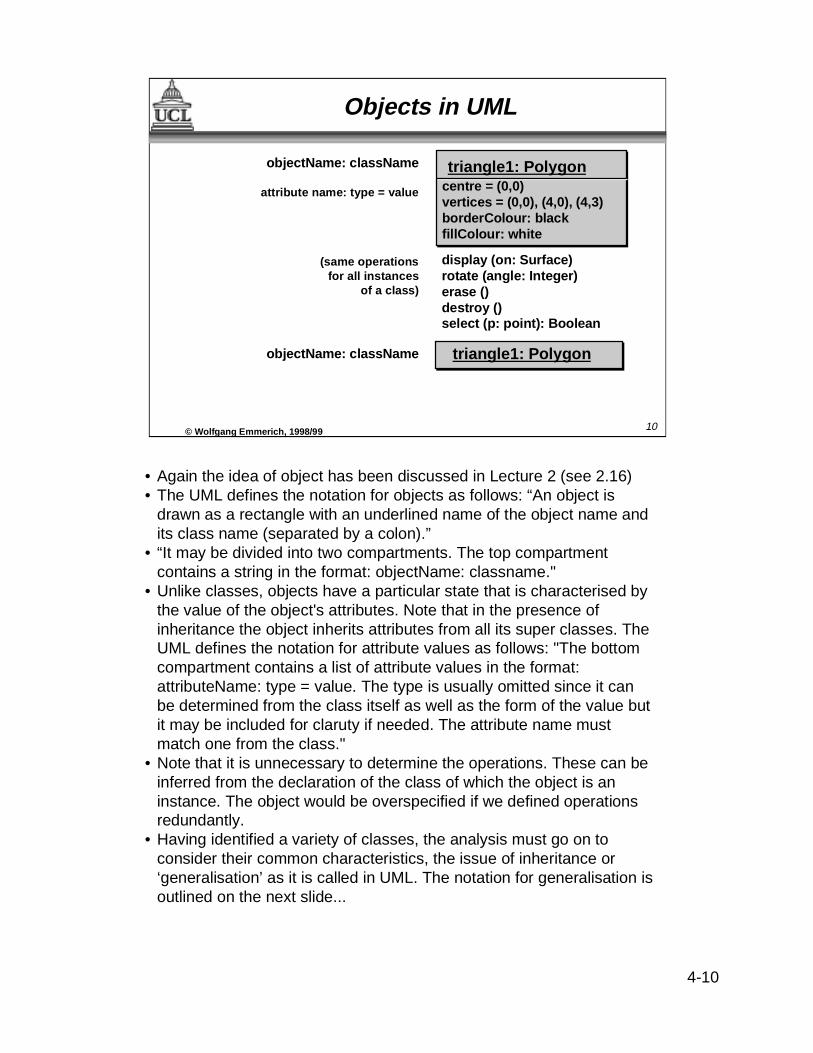
• Again the idea of object has been discussed in Lecture 2 (see 2.16)• The UML defines the notation for objects as follows: “An object is
drawn as a rectangle with an underlined name of the object name andits class name (separated by a colon).”
• “It may be divided into two compartments. The top compartmentcontains a string in the format: objectName: classname."
• Unlike classes, objects have a particular state that is characterised bythe value of the object's attributes. Note that in the presence ofinheritance the object inherits attributes from all its super classes. TheUML defines the notation for attribute values as follows: "The bottomcompartment contains a list of attribute values in the format:attributeName: type = value. The type is usually omitted since it canbe determined from the class itself as well as the form of the value butit may be included for claruty if needed. The attribute name mustmatch one from the class."
• Note that it is unnecessary to determine the operations. These can beinferred from the declaration of the class of which the object is aninstance. The object would be overspecified if we defined operationsredundantly.
• Having identified a variety of classes, the analysis must go on toconsider their common characteristics, the issue of inheritance or‘generalisation’ as it is called in UML. The notation for generalisation isoutlined on the next slide...
10© Wolf gang Emmerich, 1998/99
objectName: className
attribute name: type = value
(same operationsfor all instances
of a class)
objectName: className
triangle1: Polygoncentre = (0,0)vertices = (0,0), (4,0), (4,3)borderColour: black fillColour: white
display (on: Surface) rotate (angle: Integer) erase () destroy () select (p: point): Boolean
Objects in UML
triangle1: Polygon

4-11
• The concept of inheritance was introduced in Lecture 2 (see 2.18 and2.19). We now present the UML language constructs for it.
• In UML ‘generalisation’ is used as a replacement, or synonym, for‘inheritance’ in OOSE, but UML documents still refer to ‘inheritance’(“Inheritance is a taxonomic relationship between a superclass and itssubclasses. It is often called generalisation or specialisationdepending on whether one is going from subclass to super class orfrom superclass to subclass. ... All attributes, operations andassociations are inherited by all subclasses.”)
• Inheritance is defined in the class diagram as “a directed line with aclosed, unfilled triangular arrowhead at the superclass end” (UMLV0.91 p7).
• The UML accommodates multiple inheritance (see 2.20). The numberof arrows that may start at a class is, therefore, not limited to one.
• Inheritance (‘generalisation’) is one of the two types of relationshipswhich are extensively used in any analysis model / initial classdiagram; the other relationship is that of association that we detail onthe next slide...
11© Wolfgang Emmerich, 1998/99
ResearcherLecturerLibrarian
Staff Member
SUBCLASS SUBCLASS SUBCLASS
SUPERCLASS
MouseHandlerKeyboardHandler
Handler
UML Generalization
JoystickHandler
4-12
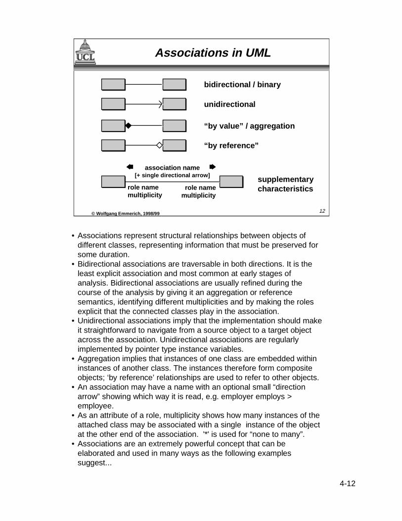
• Associations represent structural relationships between objects ofdifferent classes, representing information that must be preserved forsome duration.
• Bidirectional associations are traversable in both directions. It is theleast explicit association and most common at early stages ofanalysis. Bidirectional associations are usually refined during thecourse of the analysis by giving it an aggregation or referencesemantics, identifying different multiplicities and by making the rolesexplicit that the connected classes play in the association.
• Unidirectional associations imply that the implementation should makeit straightforward to navigate from a source object to a target objectacross the association. Unidirectional associations are regularlyimplemented by pointer type instance variables.
• Aggregation implies that instances of one class are embedded withininstances of another class. The instances therefore form compositeobjects; ‘by reference’ relationships are used to refer to other objects.
• An association may have a name with an optional small “directionarrow” showing which way it is read, e.g. employer employs >employee.
• As an attribute of a role, multiplicity shows how many instances of theattached class may be associated with a single instance of the objectat the other end of the association. '*' is used for “none to many”.
• Associations are an extremely powerful concept that can beelaborated and used in many ways as the following examplessuggest...
12© Wolf gang Emmerich, 1998/99
bidirectional / binary
unidirectional
“by value” / aggregation
“by reference”
role namemultiplicity
role namemultiplicity
supplementary characteristics
association name[+ single directional arrow]
Associations in UML

4-13
• In the relational data model relationships can have attributes in orderto characterise properties of relationships. For the same reason,associations in the UML can have specific properties by attaching aclass to them. The object-oriented approach is even more powerfulthan the relational approach because properties of associations maynot only be attributes, but also operations and other relationships. The‘association class’ is represented by a class rectangle attached by adashed line to the main link, as shown in left-hand example.
• In the example, the 'authorised_on' relationship has attributes thatidentify the priorities and privileges that go with the authorisation andan operation that is used to check the authorisation during the startupof a session. The 'association class' also has an association thatidentifies the home directory for each potential authorisation record.Assuming that the user has the same home directory on everyworkstation the multiplicity of this association is many to one.
• The right hand diagram shows a very small segment of the UML ‘metamodel’. The purpose of the meta model is to the notation itself toidentify how the notation is structured. This example represents theclass of objects containing all class object declarations.
• Now that we know all the ingredients we can start modelling a classdiagram ...
13© Wolf gang Emmerich, 1998/99
User Workstationauthorised on >
home directory
* *
*1
Authorisationprioritiesprivileges
start session()
OperationAttribute
AttributesOfClass
OperationOfClass1
1
* *
Association Examples in UML
ClassDecl
Directory

4-14
• The purpose of a class diagram is to provide a generic description ofpossible system states. This is done in a class diagram by modellingclasses that describe the common static properties of similar domainobjects.
• At this stage of modelling we are only concerned with identifying theattributes of classes and to analyse similarities in order to identifygeneralisation relationships.
• Please note that class diagrams describe the system from a type levelperspective. They are, therefore, not concerned with particular objectsthat are instances of classes.
• Class diagram provides a single, albeit essential, view of a system.The class diagram is the core of the UML and other views organisedaccording to the class diagram. The other views are provided by: usecase model (3.13) sequence diagram showing interaction between setof objects (part of design model) and state diagram showing temporalevolution of an object of a given class (also part of design model).
• We are now in a position to attempt the first stage in the production ofthe analysis model (10 on 4.5) using the output from the requirementsmodel as input...
14© Wolf gang Emmerich, 1998/99
Class Diagrams in UML
■ Class diagrams :• show logical, static structure of system• provide core of ‘unified model’
■ Generation of initial class diagram fromproblem domain object list• classes of objects• associations / attributes• inheritance relationships

4-15
• This slide depicts the initial class diagram that we have derived fromthe use case descriptions of the recycling machine example. This ishow we got there:
• We have started from the list of domain objects produced as part ofthe requirements model and have drawn a class representation foreach of the items.
• After that, we have assigned different domain attributes in order tomodel states of real world objects.
• When we had identified the attributes of classes, we recognised thatcans, bottles and crates have several attributes in common. In order toavoid this duplication we have done a generalisation and created theclass 'Deposit Item', declared these attributes for Deposit Item andthen introduced the generalisation relationship.
• Note that it need not be done this way around. We could also havespotted an abstract class for deposit item, declared the attributes andthen introduced the generalisation relationship.
• As a first plausibility check we can see whether every attribute definedin a generalised class makes sense in every single subclass.
• Note that the class diagram produced now is far from being complete.Operation specifications are missing. Also the class diagramrepresents one of any number of alternatives, e.g. to define a class ofobjects which contain dimensional measurements for any recycleableitem, or alter ‘Deposit Item’ to include these.
• The question that arises now is how do we proceed to improve such adraft diagram? The clue is that we have essential output from therequirements model stage, the use cases...
15© Wolf gang Emmerich, 1998/99
ReceiptTotal cansTotal bottlesTotal crates
Customer panel
Operator panel
CanWidthHeight
BottleNeckLengthBottom
CrateWidthHeightLength
Deposit ItemNameDeposit valueDaily total
A ‘Recycling Machine’ Class Diagram

4-16
• In order to complete and refine the class diagram we employ the usecases and the list of domain objects that have been generated as partof the requirements model.
• We take each single use case and describe for each class containedin the initial class diagram the role and the responsibility of the class ina textual description. This exercise will result in the first analysis modeloutput in form of textual description of each object’s role andresponsibilities.
• We then distribute the behaviour that we have identified in the usecases by assigning operations to objects. We will have to make surethat each behavioural description is covered by an operation.
• At the later design stage it might become necessary to delegateoperations to other classes but we do not worry about this during theanalysis stage.
• Also this exercise is likely to result in a proliferation of odd classes,e.g. receipt printer, alarm device, bottle slot. Consequently we needsome means of differentiating the purpose of system elements thathave been identified.
• Jacobson provides a categorisation of classes which is a useful aid toanalysis. He suggests three different categories according to the rolesthat classes can play. The next slide details these roles of classes...
16© Wolf gang Emmerich, 1998/99
Exploiting Use Cases
■ Employ classes and use cases, one by one,• to describe roles and responsibilities of each
class• to distribute behaviour specified in use cases• to ensure that there is a for every behaviour
4-17
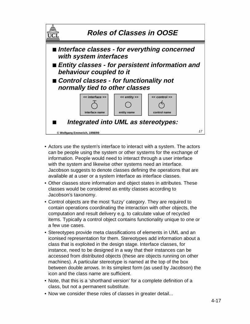
• Actors use the system's interface to interact with a system. The actorscan be people using the system or other systems for the exchange ofinformation. People would need to interact through a user interfacewith the system and likewise other systems need an interface.Jacobson suggests to denote classes defining the operations that areavailable at a user or a system interface as interface classes.
• Other classes store information and object states in attributes. Theseclasses would be considered as entity classes according toJacobson's taxonomy.
• Control objects are the most ‘fuzzy’ category. They are required tocontain operations coordinating the interaction with other objects, thecomputation and result delivery e.g. to calculate value of recycleditems. Typically a control object contains functionality unique to one ora few use cases.
• Stereotypes provide meta classifications of elements in UML and aniconised representation for them. Stereotypes add information about aclass that is exploited in the design stage. Interface classes, forinstance, need to be designed in a way that their instances can beaccessed from distributed objects (these are objects running on othermachines). A particular stereotype is named at the top of the boxbetween double arrows. In its simplest form (as used by Jacobson) theicon and the class name are sufficient.
• Note, that this is a ‘shorthand version’ for a complete definition of aclass, but not a permanent substitute.
• Now we consider these roles of classes in greater detail...
17© Wolf gang Emmerich, 1998/99
■ Interface classes - for everything concernedwith system interfaces
■ Entity classes - for persistent information andbehaviour coupled to it
■ Control classes - for functionality notnormally tied to other classes
■ Integrated into UML as stereotypes:
<< interface >>
interface name
<< entity >>
entity name
<< control >>
control name
Roles of Classes in OOSE
4-18
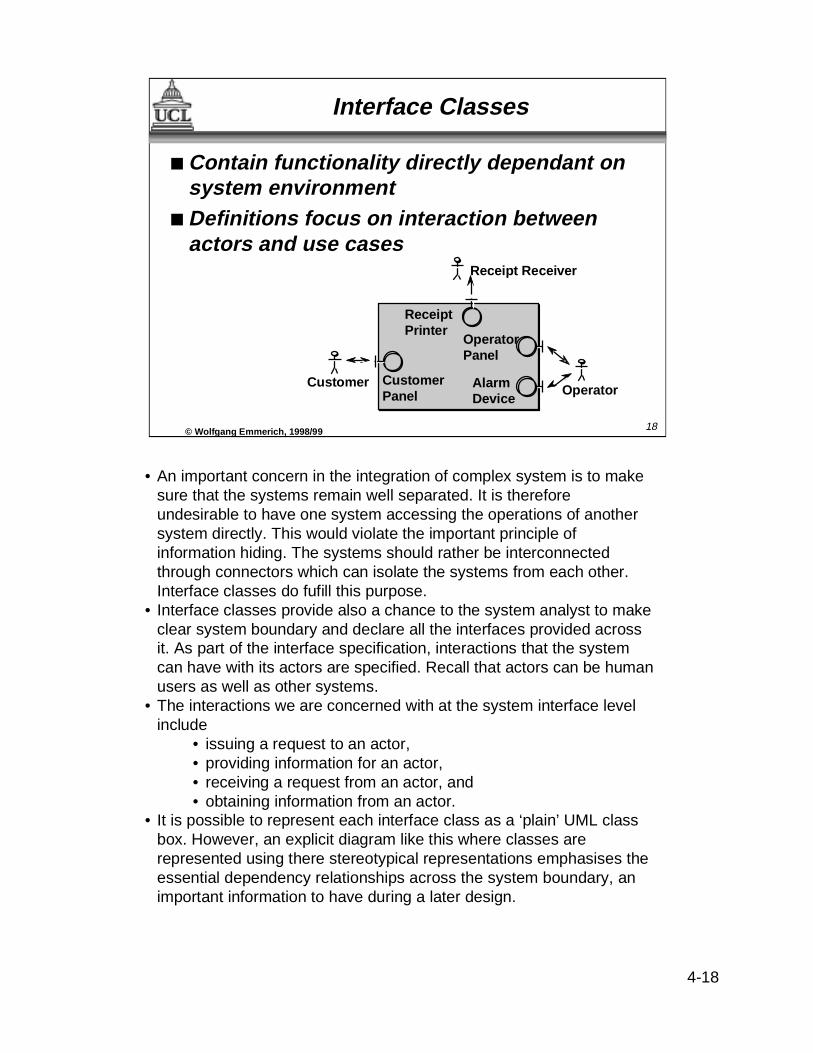
• An important concern in the integration of complex system is to makesure that the systems remain well separated. It is thereforeundesirable to have one system accessing the operations of anothersystem directly. This would violate the important principle ofinformation hiding. The systems should rather be interconnectedthrough connectors which can isolate the systems from each other.Interface classes do fufill this purpose.
• Interface classes provide also a chance to the system analyst to makeclear system boundary and declare all the interfaces provided acrossit. As part of the interface specification, interactions that the systemcan have with its actors are specified. Recall that actors can be humanusers as well as other systems.
• The interactions we are concerned with at the system interface levelinclude
• issuing a request to an actor,• providing information for an actor,• receiving a request from an actor, and• obtaining information from an actor.
• It is possible to represent each interface class as a ‘plain’ UML classbox. However, an explicit diagram like this where classes arerepresented using there stereotypical representations emphasises theessential dependency relationships across the system boundary, animportant information to have during a later design.
18© Wolf gang Emmerich, 1998/99
Receipt Receiver
CustomerOperator
Receipt Printer
Operator Panel
Alarm Device
Customer Panel
Interface Classes
■ Contain functionality directly dependant onsystem environment
■ Definitions focus on interaction betweenactors and use cases
4-19
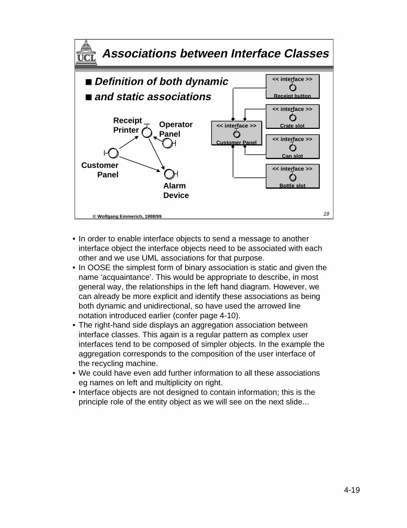
• In order to enable interface objects to send a message to anotherinterface object the interface objects need to be associated with eachother and we use UML associations for that purpose.
• In OOSE the simplest form of binary association is static and given thename ‘acquaintance’. This would be appropriate to describe, in mostgeneral way, the relationships in the left hand diagram. However, wecan already be more explicit and identify these associations as beingboth dynamic and unidirectional, so have used the arrowed linenotation introduced earlier (confer page 4-10).
• The right-hand side displays an aggregation association betweeninterface classes. This again is a regular pattern as complex userinterfaces tend to be composed of simpler objects. In the example theaggregation corresponds to the composition of the user interface ofthe recycling machine.
• We could have even add further information to all these associationseg names on left and multiplicity on right.
• Interface objects are not designed to contain information; this is theprinciple role of the entity object as we will see on the next slide...
19© Wolf gang Emmerich, 1998/99
Receipt Printer
Operator Panel
Alarm Device
CustomerPanel
<< interface >>
Customer Panel
<< interface >>
Crate slot
<< interface >>
Bottle slot
<< interface >>
Can slot
<< interface >>
Receipt button
Associations between Interface Classes
■ Definition of both dynamic■ and static associations

4-20
• The classes modelling the domain objects that were part of the listproduced at the end of the requirements stage will be classified asentity classes.
• Entity classes typically have attributes that are capable of storinginformation. As class diagrams are at type level, we are not concernedabout actual attribute values. Only objects that have been instantiatedfrom the class have different attribute values.
• This diagram shows the next stage of elaboration of classes to includeattribute types. The typing of attributes restricts the domain that thevalue of these attributes can have in objects instantiated from theclass.
• The domain might even further be restricted but this restriction isusually implemented by operations.
• A negative daily total value would not make sense for instantiations ofany deposit item. This, so called, integrity constraint is thenimplemented by operations that would not allow the assignment ofnegative values to the attribute.
• Hence the next step to consider is the behavioural specification forclasses (the third compartment). This is dictated by operations andmessages that are sent between objects in order to invoke theoperations.
20© Wolf gang Emmerich, 1998/99
<< entity >>Deposit Item
Name: StringDeposit value: ECUDaily total: Integer
<< entity >>Crate
<< entity >>Can
<< entity >>Bottle
Attributes of Entity Classes
■ Purposes of entityclasses :• To store information
persisting aftercompletion of a use case
• To define behaviour formanipulating thisinformation
4-21
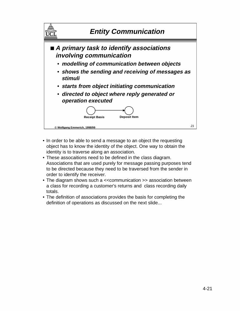
• In order to be able to send a message to an object the requestingobject has to know the identity of the object. One way to obtain theidentity is to traverse along an association.
• These assocaitions need to be defined in the class diagram.Associations that are used purely for message passing purposes tendto be directed because they need to be traversed from the sender inorder to identify the receiver.
• The diagram shows such a <<communication >> association betweena class for recording a customer's returns and class recording dailytotals.
• The definition of associations provides the basis for completing thedefinition of operations as discussed on the next slide...
21© Wolf gang Emmerich, 1998/99
Receipt Basis Deposit Item
Entity Communication
■ A primary task to identify associationsinvolving communication• modelling of communication between objects• shows the sending and receiving of messages as
stimuli• starts from object initiating communication• directed to object where reply generated or
operation executed

4-22
• Operations provided by entity classes are defined for the abovepurposes.
• Operations that store information typically check integrity constraintsof the object (e.g. to make sure that the daily total value does notbecome negative and that positive values are added only). Operationsdefining the fetching of information typically check access rights of theprincipal requesting the information before providing it.
• Special operations define the creation and removal of objects. Anoperation that creates a new object by instantiating a class is referredto as a constructor while the operation that removes an existing objectis referred to as a destructor. Constructors typically perform attributeinitialisations and destructors release storage space occupied by theobject.
• Other operations may be provided in order to implement different statetransitions that objects of the specified class might be involved in.
• In general operations are used in order to hide object states thatshould not be exposed to other objects. This contributes to theprinciple of information hiding (though on a finer level of granularitythan interface classes) (for a discussion of information hiding refer toslides 2-12 and 2-13)
• Note that Jacobson's OOSE method does not consider it to beessential to define specific operations at the analysis stage.
• Now we discuss the third role that classes can play, which is the leastclear defined...
22© Wolf gang Emmerich, 1998/99
<< entity >>Deposit Item
Name: StringDeposit value: ECUDaily total: Integer
Create ()setValue (integer)Increment ()
Entity Operations
■ Defining entity operations for:• storing and fetching information• creating and removing object• behaviour that must change if
entity object is changed

4-23
• Even in object-oriented decompositions of systems, there issometimes a need for accomodating functions in order to modelbehaviour that does not directly relate to properties of objects. Thisbehaviour is modelled as operations of classes that are controlclasses.
• Control classes provide the glue between interface classes and entityclasses. To construct stable systems in the real world, one should notuse too much glue but only use it to fill the gaps between components.This is the same with object-oriented modelling. Control classesshould be deployed with care.
• Control classes should be used to represent use cases involve someform of coordination operation, such as
•transaction-related behaviour,•specific control sequences, and•functions separating interface and entity objects
• The algorithms performed by these coordination operations aresubject to frequent change. That makes it necessary to isolate them inseparate objects to be maintained separately.
• In a preliminary draft assign one control object to each use case.Where the situation is more complex, aim for one per actor. Theemphasis, as before, is on usefulness of use cases.
• With all these objects we can build up ‘use case views’ and packagesas shown on the next slide...
23© Wolf gang Emmerich, 1998/99
extends
deposit item receiver
alarm device
information administrator
report generator
Control Classes
■ Control classes needed toprovide for:• behaviour not natural in
interface and entity classes• ’glue’ between other classes
in use case• typical control behaviours• improved maintainability

4-24
• The next step in the analysis is to take each use case and model it interms of a class diagram fragment. This is a significant step towardsthe formalisation of use cases and a test whether all the classes areprovided that are needed for the use cases.
• Note that the same class might occur in many different fragments inthe same way as the same actors and real world entities occur indifferent use cases.
• The diagram on this slide shows part model only of objects supportinguse case ‘Returning item’.
• As a next check we will convince ourselves and any stakeholders thatwhat we have modelled in terms of classes really reflects the realworld. This is examplified on the next slide...
24© Wolf gang Emmerich, 1998/99
1 0 .. n
Receipt printer
Customer Panel
Receipt Basis
Deposit Item Receiver
Deposit Item
Can Bottle Crate
Use Case View
■ Model each use case■ Describe use case in terms of classes

4-25
• This slide displays the rewriting of the use case we had on the slidebefore in terms of classes. This is referred to as an elaborated usecase.
• This elaborated use case serves three purposes:• While performing the exercise of rewriting the use case we
double check that every information we had in the previousdescription is covered in the class diagram.
• We establish direct links between the use case and the classdiagram. This allows tracking user requirements reflected byuse cases through the analysis into the design. This traceabilityis an important basis for analysing the impact of changes to therequirements.
• Stakeholders would not necessarily be able to understand classdiagrams, though they can understand this textual description.Through validating these elaborated use cases they indirectlycheck the class diagram.
• The amalgamation of individual parts provided by ‘use caseviews’ into one whole requires some kind of modularisation. InUML there are now generic ‘packages’, which subsume OOSEsubsystems. We introduce packages on the next slide...
25© Wolf gang Emmerich, 1998/99
An elaborated Use Case
When the customer returns a deposit item the CustomerPanel’s sensors measure its dimensions. Thesemeasurements are sent to the control object Deposit ItemReceiver which checks via Deposit Item whether it isacceptable. If so, Receipt Basis increments the customertotal and the daily total is also incremented. If it is notaccepted, Deposit Item Receiver signals this back toCustomer Panel which signals NOT VALID.When the Customer presses the receipt button, CustomerPanel detects this and sends this message to Deposit ItemReceiver. Deposit Item Receiver first prints the date viaReceipt Printer and then asks Receipt Basis to go throughthe customer’s returned items and sum them. Thisinformation is sent back to Deposit Item Receiver whichasks Receipt Printer to print it out.
4-26
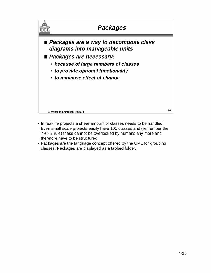
• In real-life projects a sheer amount of classes needs to be handled.Even small scale projects easily have 100 classes and (remember the7 +/- 2 rule) these cannot be overlooked by humans any more andtherefore have to be structured.
• Packages are the language concept offered by the UML for groupingclasses. Packages are displayed as a tabbed folder.
26© Wolf gang Emmerich, 1998/99
Packages
■ Packages are a way to decompose classdiagrams into manageable units
■ Packages are necessary:• because of large numbers of classes• to provide optional functionality• to minimise effect of change

4-27
27© Wolf gang Emmerich, 1998/99
Packages (Cont’d)
■ Packages should have a:• tight functional coupling inside• weak coupling outside indicated by ’dependency
associations’ between packages
■ Packages may:• ‘contain’ nested packages with ‘service packages’
as atomic parts• have individual classes outside• be result of organisational or managerial
pressures
• A package may contain classes and/or nested packages. Classesshould be arranged into packages so that there is a tight couplingwithin the package but a weak coupling in between differentpackages. Note that the generalisation relationship provides a veryvery strong coupling and it is therefore useful to arrange for classesthat inherit from each other to be in the same package.
• As classes from within one package may need to be associated withclasses contained in other packages, the need arises to interfacebetween packages. We therefore use a dependency associationbetween packages. If package A is declared to depend on package Bit will be allowed to to draw classes contained in B within A. We thennote the package from where the class has been referenced togetherwith the class name in the form <package name>::<class name>.
• Packages are useful even in small scale projects, as the recyclingmachine example shows...

4-28
• This slide displays main recycling machine package. As we see, it containsfour nested packages: Alarm, Receipt printer, Deposit and Administration.
• The dashed arrows represent dependency associations between packages.The dashed arrows starting from Deposit and leading to Alarm and Receiptprinter indicate that Deposit depends on Alarm and Receipt printer. It istherefore valid in Deposit to have references to classes contained in Receiptprinter and Alarm.
• The next slide represents the refinement of the ‘Deposit’ package...
28© Wolf gang Emmerich, 1998/99
Main
Recycling Machine Packages
Alarm
Deposit
Receipt printer
Administration

4-29
• Note that this diagram details how the Deposit package depends on the othertwo packages. It includes two so called 'referenced classes'. One is referencedfrom Receipt printer and another one is referenced from Alarm. Note how thepackage name is used as a prefix for the class name to indicate that they havebeen referenced. It then shows the associations between classes of theDeposit package.
• This means that referencing packages can add associations to other classes.In the example above we add an association to the Receipt printer class, forinstance. However, packages that reference classes cannot change attributesand operations of the class they reference.
29© Wolf gang Emmerich, 1998/99
<< interface >>
Customer Panel
<< interface >>
Crate slot
<< interface >>
Bottle slot
<< interface >>
Can slot
<< interface >>
Receipt button
<< entity >>Receipt basis
<< control >>Deposit Item
Receiver
<< entity >>Crate
<< entity >>Can
<< entity >>Bottle
<< entity >>Deposit Item
Name: StringDeposit value: ECUDaily total: Integer
Create ()setValue (integer)Increment ()
Deposit
<< interface>>Receipt printer::Printer
<< control >>Alarm::Alarmist
‘Deposit’ Package in UML

4-30
• Let us now summarise what we have done during the analysis stage.The analysis model identifies the roles of classes that model thedifferent domain objects that were specified in the requirementsmodel. The analysis model identifies three basic roles that classes canplay. These roles guide analysis and make the analysis models morerobust to change.
• The second output is the description of use cases in terms of classesand operations. This will be comprised of the text elaborating the usecase and the diagrammatic representation of the use case in terms ofclasses.
• Finally we will have generated a class diagram that is hierarchicallyorganised into packages. The class diagram displays the attributes,operations of each class and the associations the class has with otherclasses. At higher levels of abstractions, dependency relationships willbe specified between packages.
30© Wolf gang Emmerich, 1998/99
Analysis Model
■ Outputs:• class roles [text]• use case description in terms of classes and
operations [text x use case]• completed analysis model classes [diagram]• sub-system diagrams [package diagram]
■ Notations introduced:• class, object, associations• (binary, unidirectional, aggregation,
generalisation)• stereotypes (classes, associations)• package (+ dependency association)

4-31
• We have discussed the analysis stage of Jacobson's object-orientedsoftware engineering. It provides techniques such as use cases toenable a methodical basis for identifying objects, unlike othermethods. The consequence of employing use cases is thedevelopment of user perspectives of the system (improvingcommunication between users and system developers).
• The interface classes integrate the generation of user interfaces intothe mainstream method, rather than making it an add-on (as in otherapproaches).
• The marriage we have presented between OOSE and the UMLnotation provides a standardised form for outputs, and more specificinformation (particularly about operations).
• For your background reading we would suggest the followingreference:
• [JCJÖ92] Analysis. Chapter 7. pp. 153-200.
31© Wolf gang Emmerich, 1998/99
Analysis in OOSE - Summary
■ USER PERSECTIVE• Actors and Use Cases• Strong emphasis on requirements modelling• Resistence to effects of change
■ ADVANTAGES OVER OTHER METHODS• Ways to identify and define classes and objects• Effective and useful identification of roles of
classes• Recognition of user role (and interface)• Refined with practical use