D48 Dimmer Interface - Lutron Electronics · 1 0 Technical Support • 24 Hours a Day/7 Days a Week...
12
1 http://resi.lutron.com Technical Support: [email protected] INTRODUCTION SPECIFICATION & DESIGN FRONT ROOM BACK ROOM APPENDIX D48 Dimmer Interface Stand-Alone Dimmer Interface (HWI-D48) Integral Dimmer Interface (H8P5-D48-120 or H8P5-MI-D48-120) Figure 1 – Communication Wiring HWI-D48 Wired Vareo Local Lighting Controls To additional Vareo Controls Maximum 4 Vareo Controls per bus Maximum 12 buses per HWI-D48 (total maximum is 48 Wired Vareo Controls per HWI-D48) One pair #18-22 AWG (10-05 mm 2 ) twisted shielded Class 2 wire Max 500 ft (152 m) total per bus Any configuration Max 1,000 ft (305 m) total Daisy-Chain only To additional D48 Dimmer Interfaces Maximum 4 Interfaces per link (one of which may be integral to the HomeWorks Processor) Each D48 dimmer interface controls up to 48 wired Vareo ® local lighting controls and are available in two configura- tions: either integral to a HomeWorks ® wired processor or as a stand-alone component See Table 1, pg. 90 for processor details. STAND-ALONE DIMMER INTERFACES (MODEL # HWI-D48) Each stand-alone dimmer interface (model # HWI-D48) expands the capacity of the HomeWorks wired processor by providing control of up to 48 additional wired Vareo Local lighting controls Each stand-alone dimmer interface installs in either a 32-inch (81 cm) low-voltage enclosure (model # HWI-LV32-120) with a wired processor or in a 17-inch (43 cm) low-voltage enclosure (model # HWI-LV17-120) INTEGRAL D48 DIMMER INTERFACE Certain HomeWorks wired processors contain integral D48 dimmer interfaces, allowing up to 48 wired Vareo local lighting controls to be connected directly to the proces- sor Processors with integral dimmer interfaces may be installed in either a 59-inch (150 cm) remote power panel (model # HWI-PNL-8) or in a 32-inch (81 cm) low-voltage enclosure (model # HWI-LV32-120) The integral D48 dim- mer interface is always address “O,” and wired to Link 4 LOCAL LIGHTING CONTROL COMMUNICATIONS Each D48 dimmer interface has twelve communication buses that are used to communicate with the wired local lighting controls Each of the twelve buses support a maxi- mum of four uniquely-addressed wired Vareo local lighting controls The maximum total cable length for each com- munication bus is 500 feet (152 m) Buses may be wired in a daisy-chain, home run, star, or T-tap configuration CONNECTION TO WIRED PROCESSOR Each HomeWorks wired processor has configurable links, each capable of controlling up to four dimmer interfaces, one of which may be integral to the processor No more than four dimmer interfaces can be connected to a single 8 Series Dimmer Interface D48 Link N/A processor All dimmer interfaces must be connected to the same configurable link This connection requires two pair – one pair #18 AWG (10 mm2), one pair #18-22 AWG (10- 05 mm2) twisted shielded – Class 2 wire Lutron ® wire model # GRX-CBL-346S-500 may be used The maximum cable length is 1,000 feet (305 m), and this link must be wired in a daisy-chain configuration Integral Dimmer Interface Processor Board
-
Upload
truongkhue -
Category
Documents
-
view
215 -
download
0
Transcript of D48 Dimmer Interface - Lutron Electronics · 1 0 Technical Support • 24 Hours a Day/7 Days a Week...

1��http://resi.lutron.com Technical Support: [email protected]
IN
TRO
DU
CTION
SP
ECIFICATIO
N &
DESIG
N
FRO
NT R
OO
M
BA
CK R
OO
M
A
PP
END
IX
D48 Dimmer Interface
Stand-Alone Dimmer Interface(hWI-D48)
Integral Dimmer Interface(h8P5-D48-120 or h8P5-MI-D48-120)
Figure 1 – Communication Wiring
HWI-D48Wired Vareo Local Lighting Controls
To additional Vareo Controls . Maximum 4 Vareo Controls per bus . Maximum 12 buses per HWI-D48 (total maximum is 48 Wired Vareo Controls per HWI-D48) .
One pair #18-22 AWG (1 .0-0 .5 mm2) twisted shielded Class 2 wire . Max . 500 ft . (152 m) total per bus . Any configuration .
Max . 1,000 ft .(305 m) total
Daisy-Chain only
To additional D48 Dimmer Interfaces . Maximum 4 Interfaces per link (one of which may be integral to the HomeWorks Processor) .
Each D48 dimmer interface controls up to 48 wired Vareo® local lighting controls and are available in two configura-tions: either integral to a HomeWorks® wired processor or as a stand-alone component . See Table 1, pg. 90 for processor details.
S T A N D - A l O N E D I M M E R I N T E R F A C E S ( M O D E l # h W I - D 4 8 )
Each stand-alone dimmer interface (model # HWI-D48) expands the capacity of the HomeWorks wired processor by providing control of up to 48 additional wired Vareo Local lighting controls . Each stand-alone dimmer interface installs in either a 32-inch (81 cm) low-voltage enclosure (model # HWI-LV32-120) with a wired processor or in a 17-inch (43 cm) low-voltage enclosure (model # HWI-LV17-120) .
I N T E G R A l D 4 8 D I M M E R I N T E R F A C E
Certain HomeWorks wired processors contain integral D48 dimmer interfaces, allowing up to 48 wired Vareo local lighting controls to be connected directly to the proces-sor . Processors with integral dimmer interfaces may be installed in either a 59-inch (150 cm) remote power panel (model # HWI-PNL-8) or in a 32-inch (81 cm) low-voltage enclosure (model # HWI-LV32-120) . The integral D48 dim-mer interface is always address “O,” and wired to Link 4 .
l O C A l l I G h T I N G C O N T R O l C O M M U N I C A T I O N S
Each D48 dimmer interface has twelve communication buses that are used to communicate with the wired local lighting controls . Each of the twelve buses support a maxi-mum of four uniquely-addressed wired Vareo local lighting controls . The maximum total cable length for each com-munication bus is 500 feet (152 m) . Buses may be wired in a daisy-chain, home run, star, or T-tap configuration .
C O N N E C T I O N T O W I R E D P R O C E S S O R
Each HomeWorks wired processor has configurable links, each capable of controlling up to four dimmer interfaces, one of which may be integral to the processor . No more than four dimmer interfaces can be connected to a single
8 Series
Dimmer Interface
D48 Link
N/A
processor . All dimmer interfaces must be connected to the same configurable link . This connection requires two pair – one pair #18 AWG (1 .0 mm2), one pair #18-22 AWG (1 .0-0 .5 mm2) twisted shielded – Class 2 wire . Lutron® wire model # GRX-CBL-346S-500 may be used . The maximum cable length is 1,000 feet (305 m), and this link must be wired in a daisy-chain configuration .
Integral Dimmer Interface
Processor Board

1�0 Technical Support • 24 Hours a Day/7 Days a Week • 1.800.523.9466
IN
TRO
DU
CTION
SP
ECIFICATIO
N &
DESIG
N
FRO
NT R
OO
M
BA
CK R
OO
M
A
PP
END
IX
D48 Dimmer InterfaceSpecifications apply to hWI-D48 Stand-Alone Dimmer Interfaces and to Dimmer Interfaces integral to processors Model Numbers
Capacity
Input Voltage
Environment
Low-Voltage Wire Type
Low-Voltage Wiring Configuration
Low-Voltage Connections
Addressing
Diagnostics
ESD Protection
Surge Protection
Miswire Protection
Dimensions
Mounting
Shipping Weight
HWI-D48-120: Stand-Alone D48 Dimmer Interface . H8P5-D48-120: 8 Series P5 Processor with integral D48 Dimmer Interface . H8P5-MI-D48-120: 8 Series P5 Processor with integral D48 Dimmer Interface .
Controls up to 48 wired Vareo® local lighting controls .
Stand-Alone: 12 V from power supply in the HWI-LV17-120 or HWI-LV32-120 . Integral: Pre-wired in processor from factory .
Ambient operating temperature: 0 °C to 40 °C, 32 °F to 104 °F Ambient operating humidity: 0-90% humidity, non-condensing . Indoor use only .
Processor to D48 wire: Two pair – one pair #18 AWG (1 .0 mm2), one pair #18-22 AWG (1 .0-0 .5 mm2) twisted shielded – Class 2 wire . Lutron® wire model #GRX-CBL-346S-500 may be used .
D48 to wired Vareo local lighting control wire: One pair #22 AWG (0 .5 mm2) twisted shielded Class 2 wire .
Between processor and D48s: daisy-chain only . Termination required if total cable length exceeds 50 feet (15 m) . Total length of wire on any link cannot exceed 1000 feet (305 m) . Maximum four D48s per processor link that has been configured for dimmer interfaces .
Between D48 and wired Vareo local lighting controls: daisy-chain NOT required (star, T-tap, daisy-chain, etc . all permitted) . Termination not required . Total length of wire on any Vareo bus cannot exceed 500 feet (150 m) . Maximum four Vareo local lighting controls per D48 Vareo bus . Maximum twelve dimmer buses per D48 . See Fig . 1, pg . 129 .
Wired processor: One 4-pin removable terminal block . Each terminal will accept up to two #18 AWG (1 .0 mm2) wires .
Wired Vareo local lighting control: Twelve 2-pin removable terminal blocks . Each terminal will accept up to two #18 AWG (1 .0 mm2) wires .
Stand-alone: Via DIP Switch . Counts as 1 of 4 D48 addresses . See Fig. 3, pg. 131. Integral: Factory-set to address 1 .
Dimmer and processor communications, heartbeat, and power LEDs .
Meets or exceeds the IEC 61000-4-2 standard .
Meets or exceeds ANSI/IEEE standard c62 .41 .
RS-485 ports are over-voltage protected and miswire-protected against wire reversals and shorts . Vareo buses are miswire-protected against gray-violet shorts and reversals .
51⁄4 in (13 .3 cm) x 111⁄4 in (28 .6 cm)
Stand-alone: Mount inside HWI-LV32-120 or HWI-LV17-120 . Integral: Pre-mounted in wired processor H8P5-D48-120 or H8P5-MI-D48-120 .
1 lb . (0 .45 kg)

1�1http://resi.lutron.com Technical Support: [email protected]
IN
TRO
DU
CTION
SP
ECIFICATIO
N &
DESIG
N
FRO
NT R
OO
M
BA
CK R
OO
M
A
PP
END
IX
D48 Dimmer Interface (cont .)
Link Terminal Block at farthest D48
Pin 2 is NOT CONNECTED
Snap-in Standoff Location
Vareo Buses
Terminal G1Gray
HomeWorks® Vareo® #1
HomeWorks Vareo #4
Gray
Violet
Violet
Terminal V1
D48 Link Terminal Block Input Power Lugs
(Use only with HWI-LV17-120)
+15 V Feed LED
DIP Switch
Mounting Hole (8 places)
ESD Shield
Vareo Communications LED
Heartbeat LED
Processor Communications LED
Chassis Ground Wire
Figure � – Wiring and Callouts
Figure � – lT1 Installation
Maximum of 4 Wired Vareo controls per bus 48 total Wired Vareo controls per interface
Address Number and Switch Setting
Figure � – DIP Switch Settings
To processor or next D48 Dimmer Interface
UP - (ON)DOWN - (OFF) LT-1

1�� Technical Support • 24 Hours a Day/7 Days a Week • 1.800.523.9466
IN
TRO
DU
CTION
SP
ECIFICATIO
N &
DESIG
N
FRO
NT R
OO
M
BA
CK R
OO
M
A
PP
END
IX
H48 Dimmer Interface
Each H48 dimmer interface controls up to 48 wired Maestro® local controls and is available in two configura-tions: either integral to a HomeWorks® wired processor or as a stand-alone component . See Table 1, pg. 90 for processor details.
S T A N D - A l O N E D I M M E R I N T E R F A C E ( M O D E l # h W I - h 4 8 )
Each stand-alone dimmer interface (model # HWI-H48) expands the capacity of the HomeWorks wired processor by providing control of up to 48 additional wired Maestro local controls . Each stand-alone dimmer interface installs in either a 32-inch (81 cm) low-voltage enclosure (model # HWI-LV32-120) with a processor or in a 17-inch (43 cm) low-voltage enclosure (model #HWI-LV17-120) .
I N T E G R A l h 4 8 D I M M E R I N T E R F A C E
Certain HomeWorks wired processors contain integral H48 dimmer interfaces, allowing up to 48 wired Maestro local controls to be connected directly to the proces-sor . Processors with integral dimmer interfaces may be installed in either a 59-inch (150 cm) remote power panel (model # HWI-PNL-8) or in a 32-inch (81 cm) low-voltage enclosure (model # HWI-LV32-120) . The integral H48 dim-mer interface is always address “1,” and wired to Link 4 .
l O C A l l I G h T I N G C O N T R O l C O M M U N I C A T I O N S
Each H48 dimmer interface has six communication buses that are used to communicate with the wired local con-trols . Each of the six buses support a maximum of eight uniquely-addressed wired Maestro local controls . Each Maestro bus may have a max 500 ft (152 .5 m) per wire run but may not exceed 1000 ft (305 m) total per bus . Buses may be wired in a daisy-chain, home run, star, or T-tap configuration .
C O N N E C T I O N T O W I R E D P R O C E S S O R
Each HomeWorks wired processor has configurable links, each capable of controlling up to four dimmer interfaces, one of which may be integral to the processor . No more than four dimmer interfaces can be connected to a single
Stand-Alone Dimmer Interface (hWI-h48)
HWI-H48Wired Maestro
Local Lighting Controls
To additional Wired Maestro Controls . Maximum 8 Wired Maestro Controls per bus . Maximum 6 buses per HWI-H48 (total maximum is 48 Wired Maestro Controls per HWI-H48) .
One pair #18-22 AWG (1 .0-0 .5 mm2) twisted shielded Class 2 wire . Each Maestro bus may have a max 500 ft (152 .5 m) per wire run but may not exceed 1000 ft (305 m) total per bus .
Max . 1000 ft . (305 m) total
Daisy-Chain only
To additional H48 Dimmer Interfaces . Maximum 4 Interfaces per link (one of which may be integral to the HomeWorks Processor) .
Figure 1 – Communication Wiring
Integral Dimmer Interface - shown in 8 Series processor(h8P5-h48-120, h8P5-MI-h48-120,
h4P5-h48-120, or h4P5-h48-hRl-120)
4/8 Series
Dimmer Interface
H48/Q96 Link
N/A
processor . All dimmer interfaces must be connected to the same configurable link . This connection requires two pair – one pair #18 AWG (1 .0 mm2), one pair #18-22 AWG (1 .0-0 .5 mm2) twisted shielded – Class 2 wire . Lutron® wire model # GRX-CBL-346S-500 may be used . The maximum cable length is 1000 ft (305 m), and this link must be wired in a daisy-chain configuration .
Integral Dimmer Interface
Processor Board

1��http://resi.lutron.com Technical Support: [email protected]
IN
TRO
DU
CTION
SP
ECIFICATIO
N &
DESIG
N
FRO
NT R
OO
M
BA
CK R
OO
M
A
PP
END
IX
H48 Dimmer Interface (cont .)Specifications apply to hWI-h48 Stand-Alone Dimmer Interface and to Dimmer Interface integral to processorsModel Numbers
Capacity
Input Voltage
Environment
Low-Voltage Wire Type
Low-Voltage Wiring Configuration
Low-Voltage Connections
Addressing
Diagnostics
ESD Protection
Surge Protection
Miswire Protection
Dimensions
Mounting
Shipping Weight
HWI-H48-120: Stand-Alone H48 Dimmer Interface . H8P5-H48-120: 8 Series Wired Processor with integral H48 Dimmer Interface . H8P5-MI-H48-120: 8 Series Wired Processor with integral Module Interface and H48 Dimmer Interface . H4P5-H48-120: 4 Series Wired Processor with integral H48 Dimmer Interface . H4P5-H48-HRL-120: 4 Series Wired Processor with integral H48 Dimmer Interface and Hybrid Repeater Link .
Controls up to 48 wired Maestro® local lighting controls .
Stand-alone: 12 V from power supply in the HWI-LV17-120 or HWI-LV32-120 . Integral: Pre-wired in processor from factory .
Ambient operating temperature: 0 °C to 40 °C, 32 °F to 104 °F Ambient operating humidity: 0-90% humidity, non-condensing . Indoor use only .
Processor to H48 wire: Two pair – one pair #18 AWG (1 .0 mm2), one pair #18-22 AWG (1 .0-0 .5 mm2) twisted shielded – Class 2 wire . Lutron® wire model # GRX-CBL-346S-500 may be used .
H48 to wired Maestro local control wire: One pair #22 AWG (0 .5 mm2) twisted shielded Class 2 wire .
Between processor and H48s: Daisy-chain only . Termination required if total cable length exceeds 50 feet (15 m) . Total length of wire on any link cannot exceed 1000 feet (305 m) . Maximum four H48s per processor link that has been configured for Dimmer Interfaces H48/Q96 .
Between H48 and wired Maestro local controls: Daisy-chain NOT required (star, T-tap, daisy-chain, etc . all permitted) . Termination not required . Each Maestro bus may have a max 500 feet (152 .5 m) per wire run but may not exceed 1000 feet (305 m) total per bus . Maximum eight Maestro local controls per H48 Maestro bus . Maximum six dimmer buses per H48 . See Fig . 1, pg . 132 .
Wired Processor: One 4-pin removable terminal block . Terminal block will accept up to two #18 AWG (1 .0 mm2) wires .
Wired Maestro local control: Six 2-pin removable terminal blocks . Each terminal will accept up to two #18 AWG (1 .0 mm2) wires .
Stand-alone: Via DIP Switch . Counts as 1 of 4 H48 addresses . See Fig. 3, pg. 134. Integral: Factory-set to address 1 .
Dimmer and processor communications, heartbeat, and power LEDs .
Meets or exceeds the IEC 61000-4-2 standard .
Meets or exceeds ANSI/IEEE standard c62 .41 .
Maestro buses are miswire-protected against gray-violet shorts . H48 buses are non-polarized .
51⁄4 in (13 .3 cm) x 111⁄4 in (28 .6 cm)
Stand-alone: Mount inside HWI-LV32-120 or HWI-LV17-120 . Integral: Pre-mounted in wired processor H8P5-H48-120, H8P5-MI-H48-120, H4P5-H48-120, or H4P5-H48-HRL-120 .
1 lb . (0 .45 kg)

1�� Technical Support • 24 Hours a Day/7 Days a Week • 1.800.523.9466
IN
TRO
DU
CTION
SP
ECIFICATIO
N &
DESIG
N
FRO
NT R
OO
M
BA
CK R
OO
M
A
PP
END
IX
H48 Dimmer Interface (cont .)Snap-in Standoff Location
Processor Communication LEDs
H48 Link Terminal Block
Input Power Lugs
Mounting Hole(8 places)
DIP Switch
Heartbeat LED
Chassis Ground Wire
Dimmer Buses
Maestro Communication
LED
Address Number and Switch Setting
Pin 2 is NOT CONNECTED .
Note: Do not use an LT1 on a Dimmer Bus Link .
Violet
HomeWorks® Wired Maestro® Dimmer 1
HomeWorks Wired Maestro Dimmer 8
Gray
Violet
Gray
Terminal G1
Terminal V1
Figure � – Wiring Callouts
Figure � – DIP Switch Settings Figure � – lT1 Installation
Maximum of 8 Wired Maestro control per bus 48 total per interface
H48/Q96 Link Terminal Block wiring for farthest H48/Q96
To processor or next H48 dimmer interface or Q96 integratorUP - (ON)
DOWN - (OFF) LT-1

1��http://resi.lutron.com Technical Support: [email protected]
IN
TRO
DU
CTION
SP
ECIFICATIO
N &
DESIG
N
FRO
NT R
OO
M
BA
CK R
OO
M
A
PP
END
IX
Q96 Integrator for HomeWorks® and Sivoia QED®
Q 9 6 I N T E G R A T O R F O R h O M E W O R K S A N D S I v O I A Q E D ( M O D E l # h W I - Q 9 6 )
The Q96 integrator allows the HomeWorks system to pre-cisely control up to 96 individual Sivoia QED shades and draperies . Shades or draperies can be set to OPEN, CLOSED, or anywhere in between . There is no need to group shades in hardware because the Q96 integrator provides flexibil-ity to accomplish any grouping via software .
I N S T A l l A T I O N I N F O R M A T I O N
The Q96 integrator can be mounted in a HomeWorks low-voltage enclosure in place of any contact closure interface board (HWI-CCI or HWI-CCO) . See low-voltage enclosure instructions to determine where contact closure interface boards can be mounted on page 155 . If space does not permit an enclosure, the Q96 integrator can be mounted as a stand-alone device .
The Q96 receives its power from the Sivoia QED shades . A minimum of 2 shades must be connected to power the Q96 .
C O N N E C T I O N T O W I R E D P R O C E S S O R
The Q96 integrator connects to a configurable link con-figured for H48/Q96 . Up to four Q96 integrators can be connected to a H48/Q96 configurable link . Note that Q96 integrators and H48 dimmer interface boards can be used on the same link as long as their number does not exceed 4 and the total number of lighting/shading zones does not exceed 256 per processor .
For additional details on Q96 integrator & Sivoia QED wir-ing, see Appendix B: Sivoia QED Overview .
Q96 Integrator for HomeWorks and Sivoia QED (hWI-Q96)
4/8 Series
QED Interface
H48/Q96 Link
N/A

1�� Technical Support • 24 Hours a Day/7 Days a Week • 1.800.523.9466
IN
TRO
DU
CTION
SP
ECIFICATIO
N &
DESIG
N
FRO
NT R
OO
M
BA
CK R
OO
M
A
PP
END
IX
Model Number
Input Voltage
Regulatory Approvals
Environment
Low-Voltage Wire Type
Low-Voltage Wiring Configuration
Low-Voltage Connections
Addressing
Diagnostics
ESD Protection
Surge Protection
Dimensions
Mounting
Shipping Weight
HWI-Q96: Q96 Integrator for HomeWorks and Sivoia QED
12 V (from pin 2 of Sivoia QED link)
Class 2 device
Ambient operating temperature: 0 °C to 40 °C, 32 °F to 104 °F Ambient operating humidity: 0-90% humidity, non-condensing . Indoor use only .
Two pair – one pair #18 AWG (1 .0 mm2), one pair #18-22 AWG (1 .0-0 .5 mm2) twisted shielded – Class 2 wire . Lutron wire model # GRX-CBL-346S-500 may be used . For connection to Sivoia QED link, the #18 AWG wire must be used for +12 V and Common . Note: HWI-Q96 derives its power from the Sivoia QED link .
Between processor and Q96: Daisy-chain only . Termination required if total cable length exceeds 50 feet (15 m) . Total length of wire on any link can not exceed 1000 feet (305 m) . Maximum of four Q96 integrators and H48 dimmer interfaces per processor link configured for H48/Q96 . Between Q96 and Sivoia QED commuication link: Daisy-chain or home run . Termination not required . Maximum of 96 Sivoia QEDs per link . Total wire run distance for the entire Sivoia QED system can not exceed 4000 feet (1220 m) .
Between processor and Q96: One 4-pin removable terminal block . Terminal block will accept up to two #18 AWG (1 .0 mm2) wires . Between Q96 and Sivoia QED: One 4-pin removable terminal block . Terminal block will accept up to two #18 AWG (1 .0 mm2) wires .
Via DIP switch . Set DIP switches 5-6 to give the Q96 a unique address from 1 to 4 . DIP switches 1-4 should always be in the down position . Counts as one address on the H48/Q96 link . See Fig. 3, pg. 137.
Between processor and Q96: The HomeWorks “heartbeat” LED will be flashing to indicate communication with the processor . If the LED is off, check the connections . Between the Q96 and Sivoia QED: The Sivoia QED TX and RX communication LEDs are normally off . After limits have been set for each QED, Use the ‘All Open’ or ‘All Closed’ button and check the Sivoia QED communications LEDs (TX and RX) for flashing after the button is pressed .
Meets or exceeds IEC 61000-4-2 standard .
Meets or exceeds ANSI/IEEE standard c62 .41
See Fig. 1, pg. 137.
Mounts in the following enclosures: HWI-LV32-120, , HWI-LV24-120, HWI-LV17-120, and HWI-ENC-CC
1 .3 lbs . (0 .59 kg)
Q96 Integrator for HomeWorks® and Sivoia QED™ (cont .)

1��http://resi.lutron.com Technical Support: [email protected]
IN
TRO
DU
CTION
SP
ECIFICATIO
N &
DESIG
N
FRO
NT R
OO
M
BA
CK R
OO
M
A
PP
END
IX
Address Number and Switch Setting
UP - (ON)DOWN - (OFF)
Address #
Switch Settings
Figure � – DIP Switch Settings
Pin 2 is NOT CONNECTED .
Note: Do not use an LT1 on a Dimmer Bus Link .
Figure � – lT1 Installation
H48/Q96 Link Terminal Block wiring for farthest H48/Q96
To processor or next H48 dimmer interface or Q96 integrator
Figure � – Communication Wiring
Figure 1 – Dimensions
To HomeWorks processor H48/Q96 Link
To Sivoia QED Communication Link
Two pair – one pair #18 AWG (1 .0 mm2), one pair #22-18 AWG (0 .5-1 .0 mm2) twist-ed shielded – Class 2 wire . Lutron® wire model # GRX-CBL-346S-500 may be used so long as one of the #18 AWG wires is used for Common (terminal 1) . Do not connect terminal 2 .
Max . 1000 ft . (305 m) total wire run distance . Daisy-chain wiring configuration only .
Set DIP switches 5-6 to give the HWI-Q96 a unique HomeWorks H48/Q96 Link address from 1 to 4 . DIP Switches 1-4 should always be in the OFF (DOWN) position .
Four conductor #18 AWG (twisted and shielded) Class 2 wire . Lutron wire model # GRX-CBL-346S-500 may be used if the #18 AWG wires are used for +12 V and Common (terminals 1 & 2) .
Max . 4000 ft . (1 220 m) total wire run distance for Sivoia QED system . Home run or daisy-chain wiring configuration .
HomeWorks processor H48/Q96 Link Terminal Block Communications Only
Sivoia QED Communication Link Terminal Block Communications and Power
41⁄4 in (108 mm)
2 in (51 mm) Depth: 1 in
(25 mm)
Q96 Integrator for HomeWorks® and Sivoia QED™ (cont .)
49⁄16 in (116 mm)
Q96 Integrator for HomeWorks® and Sivoia QED™ (cont .)
LT-1
1�� Technical Support • 24 Hours a Day/7 Days a Week • 1.800.523.9466
IN
TRO
DU
CTION
SP
ECIFICATIO
N &
DESIG
N
FRO
NT R
OO
M
BA
CK R
OO
M
A
PP
END
IX
Module Interface
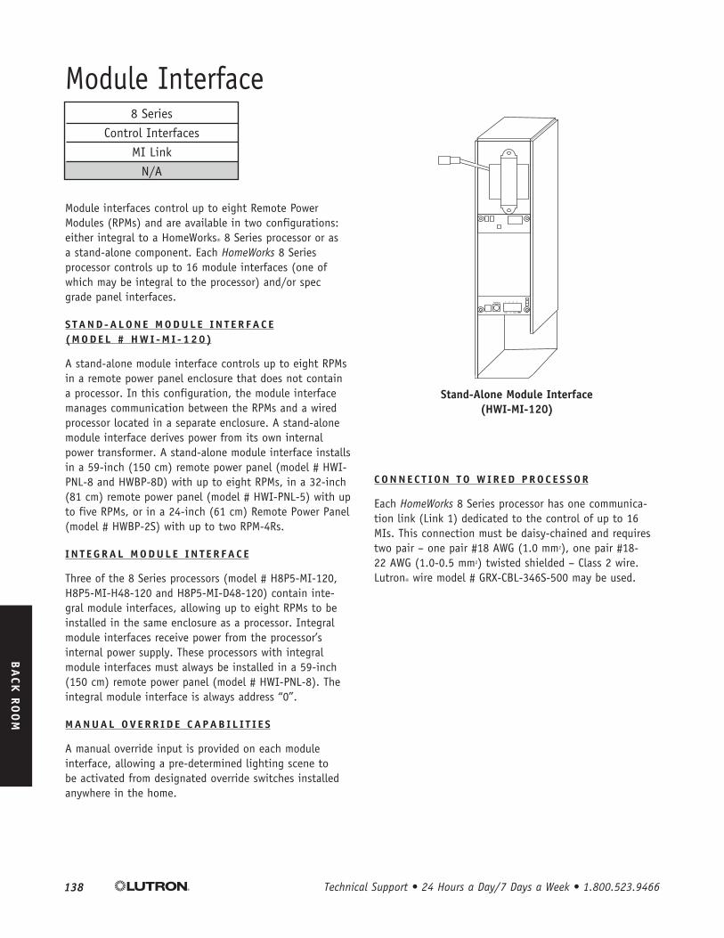
Stand-Alone Module Interface (hWI-MI-120)
Module interfaces control up to eight Remote Power Modules (RPMs) and are available in two configurations: either integral to a HomeWorks® 8 Series processor or as a stand-alone component . Each HomeWorks 8 Series processor controls up to 16 module interfaces (one of which may be integral to the processor) and/or spec grade panel interfaces .
S T A N D - A l O N E M O D U l E I N T E R F A C E ( M O D E l # h W I - M I - 1 2 0 )
A stand-alone module interface controls up to eight RPMs in a remote power panel enclosure that does not contain a processor . In this configuration, the module interface manages communication between the RPMs and a wired processor located in a separate enclosure . A stand-alone module interface derives power from its own internal power transformer . A stand-alone module interface installs in a 59-inch (150 cm) remote power panel (model # HWI-PNL-8 and HWBP-8D) with up to eight RPMs, in a 32-inch (81 cm) remote power panel (model # HWI-PNL-5) with up to five RPMs, or in a 24-inch (61 cm) Remote Power Panel (model # HWBP-2S) with up to two RPM-4Rs .
I N T E G R A l M O D U l E I N T E R F A C E
Three of the 8 Series processors (model # H8P5-MI-120, H8P5-MI-H48-120 and H8P5-MI-D48-120) contain inte-gral module interfaces, allowing up to eight RPMs to be installed in the same enclosure as a processor . Integral module interfaces receive power from the processor’s internal power supply . These processors with integral module interfaces must always be installed in a 59-inch (150 cm) remote power panel (model # HWI-PNL-8) . The integral module interface is always address “0” .
M A N U A l O v E R R I D E C A P A B I l I T I E S
A manual override input is provided on each module interface, allowing a pre-determined lighting scene to be activated from designated override switches installed anywhere in the home .
C O N N E C T I O N T O W I R E D P R O C E S S O R
Each HomeWorks 8 Series processor has one communica-tion link (Link 1) dedicated to the control of up to 16 MIs . This connection must be daisy-chained and requires two pair – one pair #18 AWG (1 .0 mm2), one pair #18-22 AWG (1 .0-0 .5 mm2) twisted shielded – Class 2 wire . Lutron® wire model # GRX-CBL-346S-500 may be used .
8 Series
Control Interfaces
MI Link
N/A

1��http://resi.lutron.com Technical Support: [email protected]
IN
TRO
DU
CTION
SP
ECIFICATIO
N &
DESIG
N
FRO
NT R
OO
M
BA
CK R
OO
M
A
PP
END
IX
Specifications apply to hWI-MI-120 Stand-Alone Module Interfaces and to Module Interfaces integral to homeWorks® ProcessorsModel Numbers
Input Voltage
Regulatory Approvals
Environment
Cooling Method
Low-Voltage Wire Type
Low-Voltage Wiring Configuration
Low-Voltage Connections
Addressing
Diagnostics
ESD Protection
Surge Protection
Miswire Protection
Fail Safe Operations
Mounting Dimensions
Mounting
Shipping Weight
Output
HWI-MI-120: Stand-Alone Module Interface . H8P5-MI-120: 8 Series Wired Processor with integral Module Interface . H8P5-MI-D48-120: 8 Series Wired Processor with integral Module Interface and D48 Dimmer Interface . H8P5-MI-H48-120: 8 Series Wired Processor with integral Module Interface and H48 Dimmer Interface .
When integral to a processor, the MI is powered by 15 V provided by terminals 1 and 2 on the processor communications link connector . When a stand-alone MI is used, it is powered by a separate line-voltage feed (120 V 50/60 Hz) at the DIN rail terminal blocks and should not have terminal 2 connected on the processor communications link connector .
UL, CSA, NOM
Ambient operating temperature: 0 °C to 40 °C, 32 °F to 104 °F Ambient operating humidity: 0-90% humidity, non-condensing . Indoor use only .
Passive cooling .
Two pair – one pair #18 AWG (1 .0 mm2), one pair #18-22 AWG (1 .0-0 .5 mm2) twisted shielded – Class 2 wire . Lutron® wire model # GRX-CBL-346S-500 may be used .
Maximum wire length of 1000 feet (305 m) . Must be wired in a daisy-chain configuration . Terminators required if total cable length exceeds 50 feet (15 m) .
One 4-pin removable terminal block . Each of the four terminals will accept up to two #18 AWG (1 .0 mm2) wires .
Via rotary switch . Counts as 1 of 16 MI addresses on an MI link .
Three LEDs for troubleshooting communications with the processor and the RPMs .
Meets or exceeds the IEC 61000-4-2 standard .
Meets or exceeds ANSI/IEEE standard c62 .41 .
All terminal block inputs are over-voltage and miswire protected against wire reversals and shorts .
The manual override scene is activated for all RPMs connected to the MI by closing a switch that is wired between the two manual override terminals . The switch (or relay) contacts must be rated for switching 50 mA at 30 V . A single switch can be used for multiple MIs wired in parallel, but proper polarity must be maintained across all units . In this configuration, the switch must be rated for the sum of the current for all of the MIs connected (e .g ., six MIs wired to a single manual override switch requires a switch rated for 300 mA at 30 V ) .
See Fig. 1, pg. 140.
See Fig. 2, 3, 4, 5, pg. 140. An integral MI is mounted within the processor housing (H8P5-MI-120, H8P5-MI-D48-120 or H8P5-MI-H48-120) . A stand-alone MI mounts in the lower right-hand corner of a panel enclosure (HWI-PNL-8 , HWBP-8D, HWI-PNL-5, and HWBP-2S) .
4 lbs . (1 .8 kg)
Compatible with HW-RPM-4U dimming module, HW-RPM-4A adaptive dimming module, HW-RPM-4FSQ fan speed module, HW-RPM-4M motor module, and HW-RPM-4R power relay module .
Module Interface (cont .)

1�0 Technical Support • 24 Hours a Day/7 Days a Week • 1.800.523.9466
IN
TRO
DU
CTION
SP
ECIFICATIO
N &
DESIG
N
FRO
NT R
OO
M
BA
CK R
OO
M
A
PP
END
IX
Module Interface (cont .)
Figure 1 – hWI-MI-120 Dimensions
Figure � - hWI-MI-120 Mounted in a hWI-PNl-5 Enclosure
Figure � – hWI-MI-120 Mounted in a hWBP-2S Enclosure
Figure � – hWI-MI-120 Mounted in a hWBP-8D Enclosure
35⁄8 in (91 mm)
3 in (75 mm)
131⁄8 in (333 mm)
Figure � - hWI-MI-120 Mounted in a hWI-PNl-8 Enclosure
Remote Power Modules (up to 8)
Module Interface
Terminal Blocks
Breakers
Main Lugs