D3196 BIOS Setup Utility for PRIMERGY CX250 S1 -...
58
Reference Manual - English D3196 BIOS Setup Utility for PRIMERGY CX250 S1 Reference Manual Edition December 2012
Transcript of D3196 BIOS Setup Utility for PRIMERGY CX250 S1 -...

Reference Manual - English
D3196 BIOS Setup Utility for PRIMERGY CX250 S1Reference Manual
Edition December 2012

Copyright and Trademarks
Comments… Suggestions… Corrections…The User Documentation Department would like toknow your opinion of this manual. Your feedback helpsus optimize our documentation to suit your individual needs.
Feel free to send us your comments by e-mail to [email protected].
Certified documentation according to DIN EN ISO 9001:2008To ensure a consistently high quality standard anduser-friendliness, this documentation was created tomeet the regulations of a quality management system which complies with the requirements of the standardDIN EN ISO 9001:2008.
cognitas. Gesellschaft für Technik-Dokumentation mbHwww.cognitas.de
Copyright © 2012 Fujitsu Technology Solutions GmbH.
All rights reserved.Delivery subject to availability; right of technical modifications reserved.
All hardware and software names used are trademarks of their respective manufacturers.
– The contents of this manual may be revised without prior notice.
– Fujitsu assumes no liability for damages to third party copyrights or other rights arising from the use of any information in this manual.
– No part of this manual may be reproduced in any form without the prior written permission of Fujitsu.
Microsoft, Windows, Windows Server, and Hyper V are trademarks or registered trademarks of Microsoft Corporation in the USA and other countries.
Intel and Xeon are trademarks or registered trademarks of Intel Corporation or its subsidiaries in the USA and other countries.

CX250 S1 D3196 - BIOS Setup Utility
Before reading this manual
For your safety
This manual contains important information for safely and correctly using this product.
Carefully read the manual before using this product. Pay particular attention to the accompanying manual "Safety Notes and Regulations" and ensure these safety notes are understood before using the product. Keep this manual and the manual "Safety Notes and Regulations" in a safe place for easy reference while using this product.
Radio interference
This product is a "Class A" ITE (Information Technology Equipment). In a domestic environment this product may cause radio interference, in which case the user may be required to take appropriate measures. VCCI-A
Aluminum electrolytic capacitors
The aluminum electrolytic capacitors used in the product's printed circuit board assemblies and in the mouse and keyboard are limited-life components. Use of these components beyond their operating life may result in electrolyte leakage or depletion, potentially causing emission of foul odor or smoke.
As a guideline, in a normal office environment (25°C) operating life is not expected to be reached within the maintenance support period (5 years). However, operating life may be reached more quickly if, for example, the product is used in a hot environment. The customer shall bear the cost of replacing replaceable components which have exceeded their operating life. Note that these are only guidelines, and do not constitute a guarantee of trouble-free operation during the maintenance support period.
High safety use
This product has been designed and manufactured to be used in commercial and/or industrial areas as a server.
When used as visual display workplace, it must not be placed in the direct field of view to avoid incommoding reflections (applies only to TX server systems).
The device has not been designed or manufactured for uses which demand an extremely high level of safety and carry a direct and serious risk of life or body if such safety cannot be assured.

D3196 - BIOS Setup Utility CX250 S1
These uses include control of nuclear reactions in nuclear power plants, automatic airplane flight control, air traffic control, traffic control in mass transport systems, medical devices for life support, and missile guidance control in weapons systems (hereafter, "high safety use"). Customers should not use this product for high safety use unless measures are in place for ensuring the level of safety demanded of such use. Please consult the sales staff of Fujitsu if intending to use this product for high safety use.
Measures against momentary voltage drop
This product may be affected by a momentary voltage drop in the power supply caused by lightning. To prevent a momentary voltage drop, use of an AC uninterruptible power supply is recommended.
(This notice follows the guidelines of Voltage Dip Immunity of Personal Computer issued by JEITA, the Japan Electronics and Information Technology Industries Association.)
Technology controlled by the Foreign Exchange and Foreign Trade Control Law of Japan
Documents produced by Fujitsu may contain technology controlled by the Foreign Exchange and Foreign Trade Control Law of Japan. Documents which contain such technology should not be exported from Japan or transferred to non-residents of Japan without first obtaining authorization in accordance with the above law.
Harmonic Current Standards
This product conforms to harmonic current standard JIS C 61000-3-2.
Only for the Japanese market:About SATA hard disk drives
The SATA version of this server supports hard disk drives with SATA / BC-SATA storage interfaces. Please note that the usage and operation conditions differ depending on the type of hard disk drive used.
Please refer to the following internet address for further information on the usage and operation conditions of each available type of hard disk drive:
http://jp.fujitsu.com/platform/server/primergy/harddisk/

CX250 S1 D3196 - BIOS Setup Utility
Content
1 Introduction . . . . . . . . . . . . . . . . . . . . . . . . . . . . 7
2 Navigating the BIOS setup utility . . . . . . . . . . . . . . . . 9
2.1 Open the BIOS setup utility . . . . . . . . . . . . . . . . . . . 9
2.2 Open the Boot menu immediately . . . . . . . . . . . . . . . . 9
2.3 Screen design . . . . . . . . . . . . . . . . . . . . . . . . . 10
2.4 Exiting the BIOS setup utility . . . . . . . . . . . . . . . . . 11
3 Main menu . . . . . . . . . . . . . . . . . . . . . . . . . . . 13
4 Advanced menu . . . . . . . . . . . . . . . . . . . . . . . . 15
4.1 Legacy OpROM Support . . . . . . . . . . . . . . . . . . . . 15
4.2 PCI Subsystem Settings . . . . . . . . . . . . . . . . . . . . 174.2.1 PCI Express Settings . . . . . . . . . . . . . . . . . . . . . . 18
4.3 WHEA Configuration . . . . . . . . . . . . . . . . . . . . . . 19
4.4 CPU Configuration . . . . . . . . . . . . . . . . . . . . . . . 194.4.1 CPU Power Management Configuration . . . . . . . . . . . . . 23
4.5 SATA Configuration . . . . . . . . . . . . . . . . . . . . . . 24
4.6 Info Report Configuration . . . . . . . . . . . . . . . . . . . 25
4.7 USB Configuration . . . . . . . . . . . . . . . . . . . . . . . 26
4.8 Super IO Configuration . . . . . . . . . . . . . . . . . . . . 264.8.1 Serial Port A Configuration . . . . . . . . . . . . . . . . . . . 26
4.9 ME Update . . . . . . . . . . . . . . . . . . . . . . . . . . . 27
4.10 Serial Port Console Redirection . . . . . . . . . . . . . . . . 274.10.1 Console Redirection Settings . . . . . . . . . . . . . . . . . . 284.10.2 Serial Port for Out-of-Band Management/Windows Emergency
Management Services (EMS) . . . . . . . . . . . . . . . . . . 30
D3196 - BIOS Setup Utility CX250 S1
Content
4.10.2.1 Console Redirection . . . . . . . . . . . . . . . . . . . . . . 304.10.2.2 Console Redirection Settings . . . . . . . . . . . . . . . . . 30
5 Chipset menu . . . . . . . . . . . . . . . . . . . . . . . . . . 33
5.1 North Bridge . . . . . . . . . . . . . . . . . . . . . . . . . . . 345.1.1 IOH Configuration . . . . . . . . . . . . . . . . . . . . . . . . . 355.1.2 QPI Configuration . . . . . . . . . . . . . . . . . . . . . . . . . 36
5.2 South Bridge . . . . . . . . . . . . . . . . . . . . . . . . . . . 37
5.3 ME Subsystem . . . . . . . . . . . . . . . . . . . . . . . . . . 38
6 Server Mgmt menu . . . . . . . . . . . . . . . . . . . . . . . 39
6.1 System Event Log . . . . . . . . . . . . . . . . . . . . . . . . 42
6.2 BMC Network Configuration . . . . . . . . . . . . . . . . . . 42
7 Boot menu . . . . . . . . . . . . . . . . . . . . . . . . . . . . 43
8 Security menu . . . . . . . . . . . . . . . . . . . . . . . . . . 47
9 Save & Exit menu . . . . . . . . . . . . . . . . . . . . . . . . 49
10 Flash BIOS Update . . . . . . . . . . . . . . . . . . . . . . . 51
10.1 Flash Memory Recovery Mode . . . . . . . . . . . . . . . . . 53
Index . . . . . . . . . . . . . . . . . . . . . . . . . . . . . . . . . . . . 57

CX250 S1 D3196 - BIOS Setup Utility 7
1 IntroductionBIOS setup utility provides settings for system functions and the hardware configuration for your system. Any changes you make take effect as soon as you save the settings and quit BIOS setup utility.
The individual menus in BIOS setup utility provide settings for the following areas:
● Main – System functions
● Advanced – Advanced system configuration
● Chipset – Access point to configure several options
● Server Mgmt – Server management
● Boot – Configuration of the start-up sequence
● Security – Security functions
● Save & Exit – Save and quit
The setting options depend on the hardware configuration of your system.
Menus or certain setting options may therefore not be available in your system's BIOS setup utility, or the menus may be in a different place, depending on the BIOS revision.

8 D3196 - BIOS Setup Utility CX250 S1
Introduction
Notational conventions
The meanings of fonts and symbols used in this manual are as follows:
Italics Commands, menu items, path names, and file names
fixed font System outputsemi-bold fixed font Text you have to enter via the keyboard"Quotation marks" Names of chapters and terms that are being
emphasizedÊ Activities that must be performed in the shown
order[Abc] Key on the keyboardI Additional information, notes and tips
V CAUTION! References, during their neglect your health, the operability of your system, or the security of your data is endangered

CX250 S1 D3196 - BIOS Setup Utility 9
2 Navigating the BIOS setup utility
2.1 Open the BIOS setup utility
Ê Start the system and wait until the screen output appears.
Ê Press the [F2] function key.
Ê If a password is assigned, enter this password and confirm with the [Enter] key.
The BIOS setup utility Main menu will be displayed on the screen.
When the Main menu does not appear:
– If the Main menu does not appear by pressing the [F2] function key, press the [Ctrl] + [Alt] + [Delete] keys at the same time to restart the system, then start up BIOS setup utility Utility.
2.2 Open the Boot menu immediately
Use this function if you do not want to start your system from the first drive that is set in the Boot menu under the Boot Option Priorities menu item.
Ê Start the system and wait until the screen output appears.
Ê Press the [F11] function key. The Boot menu will be displayed as a popup window.
Ê Use the Ê or Ë cursor keys to select the drive from which you want to start the operating system, and confirm your selection by pressing the [Enter] key. The selection options are the same as in the Boot menu.
I The selected option applies to the current system start. The next time you start the system, the settings in the Boot menu will apply again.
Ê To start the BIOS setup utility, select the Enter Setup parameter and confirm your selection with the [Enter] key.
10 D3196 - BIOS Setup Utility CX250 S1
Navigating the BIOS setup utility
2.3 Screen design
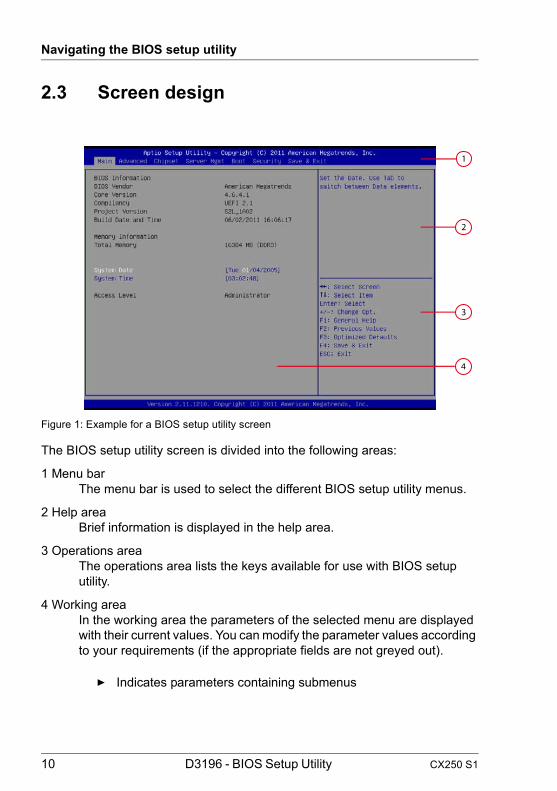
Figure 1: Example for a BIOS setup utility screen
The BIOS setup utility screen is divided into the following areas:
1 Menu barThe menu bar is used to select the different BIOS setup utility menus.
2 Help areaBrief information is displayed in the help area.
3 Operations areaThe operations area lists the keys available for use with BIOS setup utility.
4 Working areaIn the working area the parameters of the selected menu are displayed with their current values. You can modify the parameter values according to your requirements (if the appropriate fields are not greyed out).
Ê Indicates parameters containing submenus
1
2
4
3

CX250 S1 D3196 - BIOS Setup Utility 11
Navigating the BIOS setup utility
2.4 Exiting the BIOS setup utility
Ê In the Save & Exit menu select the required parameter and press the [Enter] key.
12 D3196 - BIOS Setup Utility CX250 S1
Navigating the BIOS setup utility

CX250 S1 D3196 - BIOS Setup Utility 13
3 Main menuThe following parameters can be set in this menu. Some of them are only available under special preconditions.
Figure 2: Example for the "Main" menu
BIOS InformationThe BIOS Information window displays an overview about the BIOS. This includes memory configuration data.
System Time / System Date Displays the current date/time set on the system.
The system time has the format HH:MM:SS, and the system date has the format DOW (day of week)/MM/DD/YYYY.
To change the current time/date settings enter the new time/date in the System Time/System Date fields respectively. Use the [Tab] key to move the cursor within the System Time and the System Date fields.

14 D3196 - BIOS Setup Utility CX250 S1
Main menu
I If the system time and date are lost after you switch the system off and back on again, the lithium battery is empty and needs to be replaced.
Refer to the "PRIMERGY CX250 S1 Server Upgrade and Maintenance Manual" for information on how to replace the lithium battery.
Access LevelDisplays the current Access Level in BIOS setup utility.
AdministratorIn case the system is not password protected the Access Level is Administrator.
UserIn case Administrator Password were assigned entering BIOS Setup Menu without a Password, the access level will be User.
If Administrator and User password are assigned the Access Level depends on the password used for entering BIOS setup utility.
CX250 S1 D3196 - BIOS Setup Utility 15
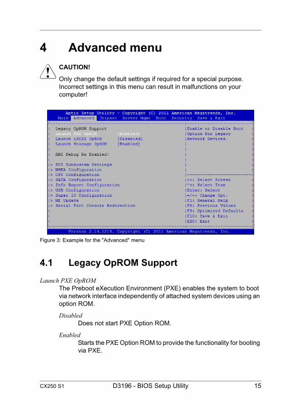
4 Advanced menuV CAUTION!
Only change the default settings if required for a special purpose. Incorrect settings in this menu can result in malfunctions on your computer!
Figure 3: Example for the "Advanced" menu
4.1 Legacy OpROM Support
Launch PXE OpROMThe Preboot eXecution Environment (PXE) enables the system to boot via network interface independently of attached system devices using an option ROM.
DisabledDoes not start PXE Option ROM.
EnabledStarts the PXE Option ROM to provide the functionality for booting via PXE.

16 D3196 - BIOS Setup Utility CX250 S1
Advanced menu
I To boot via PXE, press the [F12] key to start the boot menu, or change the settings of the Boot Option Priorities in the Boot Menu.
Launch iSCSI OpROMLAN controllers can be used as boot devices if a suitable Option ROM is started during BIOS POST. This parameter specifies whether an Option ROM should be started for LAN 1 and if so which type of Option ROM.
DisabledDoes not start any Option ROM.
iSCSIStarts the iSCSI Option ROM to provide the functionality for booting via iSCSI.
Launch Storage OpROMEnables or disable Boot Option for Legacy Mass Storage Devices with Option ROM.
DisabledBoot Option is disabled.
EnabledBoot Option is enabled.
PCI Subsystem SettingsCalls a submenu used to set up the PCI slots and PCI components on the system board (see "PCI Subsystem Settings" on page 17).
WHEA configuration Calls a submenu to set General WHEA Configuration settings (see section "WHEA Configuration").
CPU ConfigurationCalls a submenu used to make additional processor settings (see "CPU Configuration" on page 19).
The adjustment options available in this submenu depend on the processor being used.
SATA ConfigurationCalls a submenu containing the settings for the corresponding SATA controller (see "SATA Configuration" on page 24).
Info Report Configuration Calls a submenu to configure the Info Report (see section "Info Report Configuration").

CX250 S1 D3196 - BIOS Setup Utility 17
Advanced menu
USB Configuration Calls a submenu used to set up the USB components on the system board (see "USB Configuration" on page 26).
Super IO ConfigurationCalls a submenu used to configure System Super IO Chip parameters (see "Super IO Configuration" on page 26).
ME UpdateCalls a submenu used to start the recovery mode (see "ME Update" on page 27).
Serial Port Console RedirectionCalls a submenu used to view and set parameters for the terminal communication via Serial Port Console Redirection. Some of them are only available under special preconditions (see "Serial Port Console Redirection" on page 27).
4.2 PCI Subsystem Settings
The following parameters can be set in this menu. Some of them are only available under special preconditions.
PCI ROM Priority Specifies what PCI Option ROMs are launched if multiple Option ROMs are available.
Legacy ROM Legacy Option ROMs are launched.
EFI Compatible ROM EFI Compatible Option ROMs are launched.
I The option EFI Compatible ROM is only valid for RX100S7p!

18 D3196 - BIOS Setup Utility CX250 S1
Advanced menu
4.2.1 PCI Express Settings
Maximum Payload Sets Maximum Payload of PCI Express Device or allows system BIOS to select the value.
128, 256, 512, 1024, 2048, 4096 bytes The maximum payload is set to a certain value.
Auto The value of the maximum payload is selected by the system BIOS.
ASPM Support Active State Power Management (ASPM) is used to power-manage the PCI Express links, thus consuming less power. Even if ASPM is generally enabled by this selection, it will only be enabled for a specific link if the appropriate PCI Express expansion card or onboard controller supports it also.
Disabled ASPM is disabled. Power consumption for PCI Express links is not reduced. Best compatibility.
Auto Tries to configure maximum possible energy saving. Low power mode for PCI Express links is set to L0s (one direction) or L1 (bidirectional).
Force L0s Low power mode for PCI Express links is set to L0s (one direction). Tradeoff between compatibility and energy saving.
I The latency for PCI Express devices may increase if ASPM is not disabled. Several expansion cards do not support this feature correctly, which may lead to an undefined system behavior.

CX250 S1 D3196 - BIOS Setup Utility 19
Advanced menu
4.3 WHEA Configuration
The following parameters can be set in this menu. Some of them are only available under special preconditions.
WHEA support Enables or disables Windows Hardware Error Architecture.
Disabled WHEA support is disabled.
Enabled WHEA support is enabled.
4.4 CPU Configuration
The following parameters can be set in this menu. Some of them are only available under special preconditions.
Socket x CPU Information Displays socket specific CPU information.
Hyper-Threading Hyper-threading technology allows a single physical processor core to appear as several logical processors. With this technology the operating system can better utilize the internal processor resources, which in turn leads to increased performance. The advantages of this technology can only be used by an operating system which supports ACPI. This setting has no effect on operating systems which do not support ACPI.
Disabled An ACPI operating system can only use the first logical processor of a processor core. This setting should only be used if hyper-threading technology has not been correctly implemented in the ACPI operating system.
Enabled An ACPI operating system can use all logical processors within a physical processor.

20 D3196 - BIOS Setup Utility CX250 S1
Advanced menu
Active Processor Cores For processors that contain multiple processor cores, the number of active processor cores can be limited. Inactive processor cores will not be used and hidden from the operating system.
All All available processor cores are active and can be used.
1...n Only the selected number of processor cores are active. The remaining processor cores are deactivated.
I This selection may solve problems with specific software packages or system licenses.
Limit CPUID Maximum Defines the number of CPUID functions which can be called by the processor. Some operating systems cannot process new CPUID commands which support more than three functions. This parameter should be enabled for these operating systems.
Disabled All CPUID functions are supported.
Enabled For reasons of compatibility with the operating system, only a reduced number of CPUID functions are supported by the processor.
Execute Disable Bit Defines the protection for executable memory areas (anti-virus protection). The function is only effective if it is also supported by the operating system. The eXecute Disable bit (XD bit) is also known as NX (No eXecute) bit.
Disabled Prevents the operating system from being able to switch on the function Execute Disable.
Enabled Enables the operating system to switch on the function Execute Disable.

CX250 S1 D3196 - BIOS Setup Utility 21
Advanced menu
Hardware Prefetcher If activated memory content, that is likely required, is preloaded automatically to the cache when the memory bus is inactive. Fetching content form cache instead of memory reduces the latency especially for applications with linear data access.
I With this parameter you can change the performance settings for non-standard applications. It is recommended that you should adhere to the default settings for standard applications.
Disabled Deactivates the hardware prefetcher of the CPU.
Enabled Activates the hardware prefetcher of the CPU.
Adjacent Cache Line Prefetch Available if the processor offers a mechanism for loading an additional adjacent 64 Byte cache line during every cache request of the processor. This will increase cache hit ratio for applications with high spatial locality.
I With this parameter you can change the performance settings for non-standard applications. It is recommended that you should adhere to the default settings for standard applications.
Disabled The processor loads the requested cache line.
Enabled The processor loads the requested cache line and the adjacent cache line.
DCU Streamer Prefetcher If activated data content, that is likely required, is preloaded automatically to the L1 data cache when the memory bus is inactive. Fetching content from cache instead of memory reduces the latency especially for applications with linear data access.
I With this parameter you can change the performance settings for non-standard applications. It is recommended that you should adhere to the default settings for standard applications.
Disabled Deactivates the DCU Streamer Prefetcher of the CPU.
Enabled Activates the DCU Streamer Prefetcher of the CPU.

22 D3196 - BIOS Setup Utility CX250 S1
Advanced menu
DCU IP Prefetcher Performance gains are expected when code is organized sequentially and in contiguous memory.
I With this parameter you can change the performance settings for non-standard applications. It is recommended that you should adhere to the default settings for standard applications.
Disabled Deactivates the DCU IP Prefetch of the CPU.
Enabled Activates the DCU IP Prefetch of the CPU.
Intel Virtualization Technology Supports the virtualization of platform hardware and several software environments, based on VMX (Virtual Machine Extensions) to support the use of several software environments using virtual computers. Virtualization technology extends the processor support for virtualization purposes with the 16 Bit and 32 Bit protected modes and with the EM64T (Intel® Extended Memory 64 Technology) mode.
Disabled A VMM (Virtual Machine Monitor) cannot use the additional hardware features.
Enabled A VMM can use the additional hardware features.

CX250 S1 D3196 - BIOS Setup Utility 23
Advanced menu
4.4.1 CPU Power Management Configuration
The following parameters can be set in this menu. Some of them are only available under special preconditions.
Power Technology Configures CPU power management features.
DisabledCPU power management features are disabled.
Energy EfficientCPU power management features are optimized for energy efficiency.
CustomAdditional Setup items to configure CPU power management will appear.
Energy Performance Energy efficiency policy for the processor on non-legacy Operating Systems. This is an input for the processor for tuning the power consumption and the performance.
Performance Optimization is strongly toward performance, even at the expense of energy efficiency.
Balanced Performance Weight optimization toward performance, while conserving energy.
Balanced Energy Weight optimization toward energy conservation, with good performance.
Energy Efficient Optimization is strongly toward energy efficiency, even at the expense of performance.
I According to its power policy the operating may also decide not to use the mode, which is selected in setup. It may also overrule the setup and select one of the other modes instead.

24 D3196 - BIOS Setup Utility CX250 S1
Advanced menu
4.5 SATA Configuration
The following parameters can be set in this menu. Some of them are only available under special preconditions.
SATA PortThe menus show the parameters of the SATA device.
For the SATA ports is displayed whether the SATA port is free (Not present) or which drive is connected to the SATA port.
SATA ModeDefines in which mode the SATA ports operate.
DisabledSATA interface is disabled.
IDE ModeSATA interface is in IDE Mode.
AHCI ModeSATA interface is in AHCI Mode.

CX250 S1 D3196 - BIOS Setup Utility 25
Advanced menu
4.6 Info Report Configuration
Post Report Specifies whether Post Report Support is available or not.
Disabled Post Report is disabled
Enabled Post Report is enabled.
Delay Time Specifies how much time you have to wait for the Post Report.
0 - 10 You have to wait 0 - 10 seconds until Post Report is displayed
Until press ESCYou have to press ESC to see the Post Report.
Summary Screen Specifies whether Summary Screen Support is available or not.
DisabledSummary Screen is disabled
EnabledSummary Screen is enabled.

26 D3196 - BIOS Setup Utility CX250 S1
Advanced menu
4.7 USB Configuration
USB Devices Displays number of available USB devices, USB keyboards, USB Mouse and USB Hubs.
Legacy USB Support Specifies whether Legacy USB Support is available. This function has to be enabled or set to Auto if it may be necessary to boot the operating system from a USB device.
DisabledLegacy USB Support is not available. A USB keyboard or USB mouse can only be used if supported by the operating system. The operating system cannot be booted from a USB device
EnabledLegacy USB Support is available. The USB keyboard or USB mouse can also be used with operating systems that do not support USB. The operating system can be booted from a USB device.
Auto Legacy USB Support will be disabled if no USB devices are connected.
I The Legacy USB Support function should be disabled if the operating system supports USB and you do not want to boot the operating system from USB devices.
4.8 Super IO Configuration
Displays System Super IO Chip Parameters.
Super IO Chip Displays information about Super IO Chip.
4.8.1 Serial Port A Configuration
Set Parameters of Serial Port A(COMA).

CX250 S1 D3196 - BIOS Setup Utility 27
Advanced menu
Serial Port A Specifies whether the serial port is available.
DisabledThe serial port is not available.
EnabledThe serial port is available.
Device SettingsDisplays the base I/O address and the interrupt used to access the corresponding serial port, e.g. IO=3F8h; IRQ=4.
4.9 ME Update
In this menu the ME update can be disabled in the case of BIOS update. It is not always necessary to update the BIOS and the ME subsystem. ME will run in recovery mode in this case. Sets ME to disable mode.
Set ME to disable Mode Sets ME to disable mode.
4.10 Serial Port Console Redirection
Console Redirection Enables or disables the Console Redirection.
DisabledConsole Redirection is disabled.
EnabledConsole Redirection is enabled.
28 D3196 - BIOS Setup Utility CX250 S1
Advanced menu
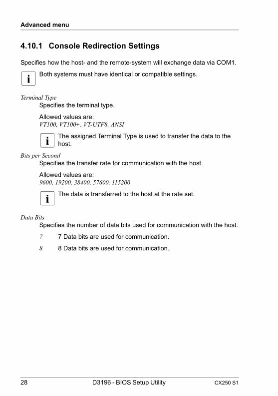
4.10.1 Console Redirection Settings
Specifies how the host- and the remote-system will exchange data via COM1.
I Both systems must have identical or compatible settings.
Terminal Type Specifies the terminal type.
Allowed values are:VT100, VT100+, VT-UTF8, ANSI
I The assigned Terminal Type is used to transfer the data to the host.
Bits per Second Specifies the transfer rate for communication with the host.
Allowed values are:9600, 19200, 38400, 57600, 115200
I The data is transferred to the host at the rate set.
Data Bits Specifies the number of data bits used for communication with the host.
7 7 Data bits are used for communication.
8 8 Data bits are used for communication.

CX250 S1 D3196 - BIOS Setup Utility 29
Advanced menu
Parity Specifies parity bit usage for communication with the host. Parity bits are used for error detection.
None No parity bit is used. No error detection available.
Even Parity bit is 0 if the number of 1s in the data bits is even.
Odd Parity bit is 0 if the number of 1s in the data bits is odd.
Mark Parity bit is always 1.
Space Parity bit is always 0.
Stop Bits Specifies the number of Stop Bits used to indicate the end of a serial data packet. Communication with slow devices may require more than 1 stop bit.
1 One Stop Bit is used.
2 Two Stop Bits are used.
Flow Control This setting determines how the transfer via the interface is controlled. This setting must be identical on both terminal and server.
None The interface is operated without transfer control.
CTS/RTS The transfer control is performed by the hardware. This mode must also be supported by the cable.

30 D3196 - BIOS Setup Utility CX250 S1
Advanced menu
VT-UTF8 Combo Key Support VT-UTF8 is the preferred terminal type for out-of-band management.
Disabled Disables VT-UTF8 Combination Key Support for ANSI/VT100 terminals.
Enabled Enables VT-UTF8 Combination Key Support for ANSI/VT100 terminals.
Putty KeyPad Select FunctionKey and KeyPad on Putty.
4.10.2 Serial Port for Out-of-Band Management/Windows Emergency Management Services (EMS)
4.10.2.1 Console Redirection
Console Redirection Specifies if Serial Port for Out-of-Band Management / Windows Emergency Management Services (EMS) is available.
Disabled EMS is not available.
Enabled EMS is available.
4.10.2.2 Console Redirection Settings
Specifies how the host- and the remote-system will exchange data via Out-of-Band Management / EMS.
I Both systems must have identical or compatible settings.
Out-of-Band Mgmt Port Assigns a serial port for Out-of-Band Management.
COM1 COM1 port is used for Out-of-Band Management.

CX250 S1 D3196 - BIOS Setup Utility 31
Advanced menu
Terminal Type Specifies the terminal type.
Allowed values are:VT100, VT100+, VT-UTF8, ANSI
I The assigned Terminal Type is used to transfer the data to the host.
Bits per Second Specifies the transfer rate for communication with the host.
Allowed values are:9600, 19200, 38400, 57600, 115200
I The data is transferred to the host at the rate set.
Flow Control This setting determines how the transfer via the interface is controlled.The setting must be the same on both terminal and server.
None The interface is operated without transfer control.
Hardware CTS/RTS The transfer control is performed by the hardware. This mode must also be supported by the cable.
Data Bits Displays the number of data bits used for communication with the host.
Parity Displays parity bit usage for communication with the host.
Stop Bits Displays the number of Stop Bits used.

32 D3196 - BIOS Setup Utility CX250 S1
Advanced menu
CX250 S1 D3196 - BIOS Setup Utility 33
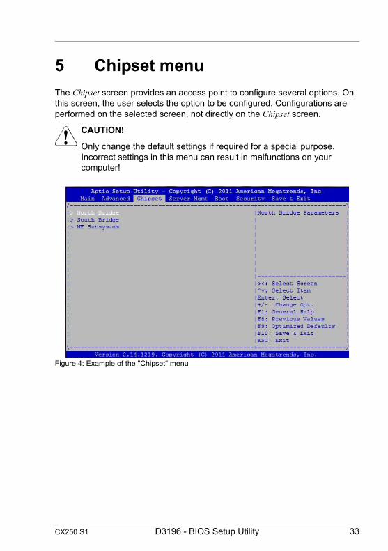
5 Chipset menuThe Chipset screen provides an access point to configure several options. On this screen, the user selects the option to be configured. Configurations are performed on the selected screen, not directly on the Chipset screen.
V CAUTION!
Only change the default settings if required for a special purpose. Incorrect settings in this menu can result in malfunctions on your computer!
Figure 4: Example of the "Chipset" menu

34 D3196 - BIOS Setup Utility CX250 S1
Chipset menu
5.1 North Bridge
The following parameters can be set in this menu. Some of them are only available under special preconditions.
IOH Configuration Calls a submenu used to configure virtualization of platform hardware and several software environments, based on VMX (Virtual Machine Extensions) to support the use of several software environments using virtual computers (see "IOH Configuration" on page 35).
QPI Configuration Calls a submenu used to configure the routing mechanism (see "QPI Configuration" on page 36).
Memory Mode Memory capacity can be reserved for possible error treatment. For detailed instructions refer to the corresponding For detailed instructions refer to "PRIMERGY CX250 S1 Server Upgrade and Maintenance Manual".
IndependentNo additional memory capacity is reserved for error treatment.
MirroringThe BIOS divides the system memory in half and retains two copies of all data in the memory. It prevents a system crash when uncorrectable errors occur. In seldom cases in which uncorrectable errors occur, data cannot be collected from the first copy, the data is immediately called from the second copy. At the same time, the memory error is reported to the administrator.
SparingThe BIOS uses a memory rank as a reserve for the case that too many correctable errors occur in another memory rank. Before some uncorrectable error occurs, the content of this memory rank is routed back into the sparing rank. The potentially defective memory rank is not used anymore. This procedure is executed while working. At the same time, the memory error is reported to the administrator.

CX250 S1 D3196 - BIOS Setup Utility 35
Chipset menu
DRAM RAPL BWLTMIT Intel recommended values.
Perfmon and DFX Devices Perfmon and DFX devices can be hidden or unhidden.
DRAM RAPL MODE DRAM RAPL Modes (Disabled/Mode0/Mode1).
NUMA Enables or disables Non Uniform Memory Access (NUMA).
5.1.1 IOH Configuration
Intel® I/OAT Enables or disables Intel® I/O Acceleration Technology (I/OAT).
Disabled Disables Intel® I/O Acceleration Technology (I/OAT)
Enabled Enables Intel® I/O Acceleration Technology (I/OAT)
Intel VT-d VT-d provides hardware support for sharing I/O devices between multiple virtual machines. VMMs (Virtual Machine Monitors) can use VT-d for managing multiple virtual machines accessing the same physical I/O device.
Disabled VT-d is disabled and not available for VMMs.
Enabled VT-d is enabled.
Coherency SupportEnables or disables VT-d engine coherency support.
Disabled VT-d engine Coherency is disabled.
Enabled VT-d engine Coherency is enabled.

36 D3196 - BIOS Setup Utility CX250 S1
Chipset menu
ATS SupportATS Support: Enables or disables VT-d Engine Address Translation Services (ATS) support.
Disabled ATS is disabled.
Enabled ATS is enabled.
5.1.2 QPI Configuration
QPI (QuickPath Interconnect) is a routing mechanism which secures that the incoming data packages from several processors are led to the correct receiving processor.
Current QPI Link Freq Displays the current QPI link frequency.
QPI Link Frequency The QPI frequency can be set to the commonly supported frequencies of the CPUs.
Auto The BIOS will find out the maximum speed depending on the CPU(s) and chipset present in your system.
6.4 GT/s, 7.2 GT/s 8.0 GT/s (CPU dependent)
Possible speed settings vary with CPU(s) and chipset so different values are displayed depending on your system. Choose one of the values to explicitly set the speed the QPI links will be run at.

CX250 S1 D3196 - BIOS Setup Utility 37
Chipset menu
5.2 South Bridge
Periodic SMI Provides a Periodic SMI (PSMI) methodology for automatic and reproduction of system-level failures.
Disabled PSMI is disabled.
Enabled PSMI is enabled.
Restore AC Power Loss Specifies what state to go to when power is re-applied after a power failure (G3 state).
Power Off The system performs a status check and then switches off.
Power On The system performs a status check and then switches on.
Last State The system performs a status check and then returns the mode it was in before the power failure occurred (On or Off).
Disable SCU devices Enables or disables Patsburg SCU devices.
Disabled Patsburg SCU device is disabled.
Enabled Patsburg SCU device is enabled.
Onboard SAS Oprom Selects which OpROM to load for Onboard SAS Controller (SCU).
Disabled No option ROM is loaded.
Intel RSTe Loads the Intel RSTe option ROM.
LSI MegaRAID Loads the LSI MegaRAID option ROM.

38 D3196 - BIOS Setup Utility CX250 S1
Chipset menu
5.3 ME Subsystem
The Intel ME Subsystem Configuration displays various information about ME.
ME subsystem ME means Management Engine.
Disabled ME subsystem is disabled.
Enabled ME subsystem is enabled.

CX250 S1 D3196 - BIOS Setup Utility 39
6 Server Mgmt menuThe following parameters can be set in this menu. Some of them are only available under special preconditions.
Figure 5: Example for the "Server Mgmt" menu
BMC firmware versionShows the BMC firmware version.
IPMI versionShows the IPMI version.
FRB-2 TimerEnables or disables the FRB-2 timer (POST timer).
If CPU failed during power-on, the FRB (Fault Resilient Boot) timer handles how to work.
Disabled The FRB-2 timer is disabled.
EnabledThe FRB-2 timer is enabled.

40 D3196 - BIOS Setup Utility CX250 S1
Server Mgmt menu
FRB-2 Timer timeoutSets the FRB-2 timer expiration value.
3 minutes The FRB-2 timer expires after 3 minutes.
4 minutes The FRB-2 timer expires after 4 minutes.
5 minutes The FRB-2 timer expires after 5 minutes.
6 minutes The FRB-2 timer expires after 6 minutes.
FRB-2 Timer PolicyConfigures how the system should respond if the FRB-2 Timer expires.
Do Nothing The system does not respond when the FRB-2 timer expires.
ResetThe system resets when the FRB-2 timer expires.
Power Down The system fulfills a shutdown when the FRB-2 timer expires.
OS Watchdog TimerIf enabled, starts a BIOS timer which can only be shut off by Intel Management Software after the OS loads. Helps determine that the OS successfully loaded or follows the O/S Boot Watchdog Timer policy.
Disabled The O/S Watchdog timer is disabled.
EnabledThe O/S Watchdog timer is enabled.
OS Wtd Timer TimeoutIf enabled, starts a BIOS timer which can only be shut off by Intel Management Software after the OS loads. Helps determine that the OS successfully loaded or follows the O/S Boot Watchdog Timer policy.
5 minutes The O/S Watchdog timer expires after 5 minutes.
10 minutes The O/S Watchdog timer expires after 10 minutes.

CX250 S1 D3196 - BIOS Setup Utility 41
Server Mgmt menu
15 minutes The O/S Watchdog timer expires after 15 minutes.
20 minutes The O/S Watchdog timer expires after 20 minutes.
OS Wtd Timer PolicyConfigure the length of the O/S Boot Watchdog Timer.
Do Nothing The system does not respond when the O/S Watchdog timer expires.
ResetThe system resets when the O/S Watchdog timer expires.
Power Down The system fulfills a shutdown when the O/S Watchdog timer Timer expires.
System Event LogCalls a submenu used to view and configure the System Event Log. Some of the parameters are only available under special preconditions (see "System Event Log" on page 42).
BMC network configurationCalls a submenu used to view and configure the BMC network. Some of parameters are only available under special preconditions (see "BMC Network Configuration" on page 42).

42 D3196 - BIOS Setup Utility CX250 S1
Server Mgmt menu
6.1 System Event Log
The following parameters can be set in this menu. Some of them are only available under special preconditions.
Erase SEL Choose options for erasing SEL.
No System Event Log will not be deleted.
Yes, on next reset System Event Log will be deleted on next reset.
Yes, on every reset System Event Log will be deleted on every reset.
6.2 BMC Network Configuration
Displays information of BMC (Baseboard Management Controller) configuration.
Configuration source Selects to configure LAN channel parameters statically or dynamically (DHCP).
Static on next reset LAN channel parameters will be statically configured on next reset.
Dynamic on next reset LAN channel parameters will be dynamically configured on next reset.
Do nothing BMC network parameters will not be modified during BIOS phase.

CX250 S1 D3196 - BIOS Setup Utility 43
7 Boot menuThe following parameters can be set in this menu. Some of them are only available under special preconditions.
Figure 6: Example for the "Boot" menu
This menu can be used to define the sequence of the drives from which the system is booted. Up to eight drives (and also, for example, USB interfaces) can be listed.
For references to the operation please see the help area in this menu.
Setup Prompt Timeout Displays the number of seconds to wait for setup activation key.
I The value 65535 (0xFFFF) means indefinite waiting.
44 D3196 - BIOS Setup Utility CX250 S1
Boot menu
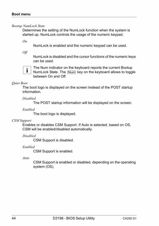
Bootup NumLock StateDetermines the setting of the NumLock function when the system is started up. NumLock controls the usage of the numeric keypad.
OnNumLock is enabled and the numeric keypad can be used.
OffNumLock is disabled and the cursor functions of the numeric keys can be used.
I The Num indicator on the keyboard reports the current Bootup NumLock State. The [Num] key on the keyboard allows to toggle between On and Off.
Quiet BootThe boot logo is displayed on the screen instead of the POST startup information.
DisabledThe POST startup information will be displayed on the screen.
EnabledThe boot logo is displayed.
CSM SupportEnables or disables CSM Support. If Auto is selected, based on OS, CSM will be enabled/disabled automatically.
DisabledCSM Support is disabled.
EnabledCSM Support is enabled.
AutoCSM Support is enabled or disabled, depending on the operating system (OS).
CX250 S1 D3196 - BIOS Setup Utility 45
Boot menu
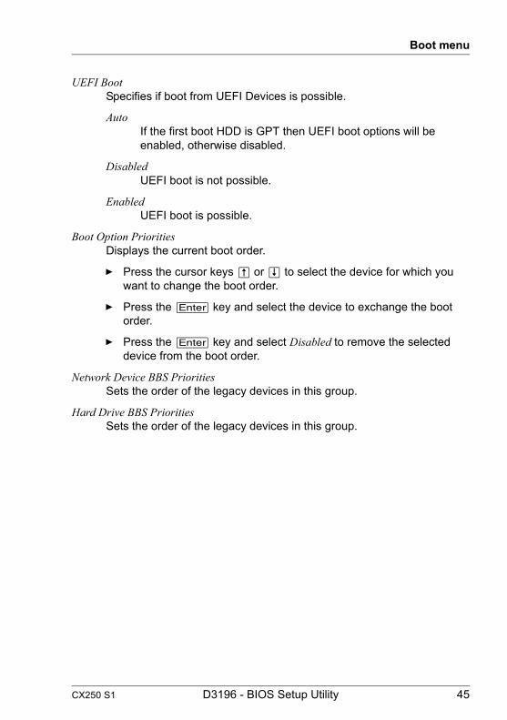
UEFI BootSpecifies if boot from UEFI Devices is possible.
AutoIf the first boot HDD is GPT then UEFI boot options will be enabled, otherwise disabled.
DisabledUEFI boot is not possible.
EnabledUEFI boot is possible.
Boot Option PrioritiesDisplays the current boot order.
Ê Press the cursor keys Ê or Ë to select the device for which you want to change the boot order.
Ê Press the [Enter] key and select the device to exchange the boot order.
Ê Press the [Enter] key and select Disabled to remove the selected device from the boot order.
Network Device BBS PrioritiesSets the order of the legacy devices in this group.
Hard Drive BBS PrioritiesSets the order of the legacy devices in this group.

46 D3196 - BIOS Setup Utility CX250 S1
Boot menu

CX250 S1 D3196 - BIOS Setup Utility 47
8 Security menuThe following parameters can be set in this menu. Some of them are only available under special preconditions.
Figure 7: Example for the "Security" menu
Only administrator password is assigned
If ONLY administrator password is assigned solely the BIOS setup utility is protected. Booting the system is unrestricted. In case of entering BIOS setup utility with administrator password you will obtain administrator level and have full access to BIOS setup utility. Entering BIOS setup utility without password results in limited BIOS setup utility access as you only obtain user level.
Only user password is assigned
If ONLY user password is assigned the BIOS setup utility as well as booting the system are protected by user password. In case of entering BIOS setup utility with user password the user obtains administrator level and has full access to BIOS setup utility. Entering the BIOS setup utility without password is prohibited.
I Deleting Administrator Password clears the User Password as well.

48 D3196 - BIOS Setup Utility CX250 S1
Security menu
The system shuts down after three times password attempts. If this happens, turn off the server, turn it back on, and then enter the correct password.
Administrator Password When you press the [Enter] key, a window opens where you can define the administrator password. Enter a character string to define a password. If you confirm an empty password field, the password will be deleted.
I To call up the complete BIOS setup utility, you need the administrator access level. If the administrator password is assigned the user password allows only a very limited access to the BIOS setup utility.
User Password When you press the [Enter] key, a window opens where you can define the user password. Enter a character string to define a password. The user password prevents unauthorized access to your system.

CX250 S1 D3196 - BIOS Setup Utility 49
9 Save & Exit menuThe following parameters can be set in this menu.
Figure 8: Example for the "Save & Exit" menu
Discard Changes and Exit Select Discard Changes and Exit followed by Yes to discard the changes you have made since entering BIOS setup utility or since invoking Save Changes. The BIOS setup utility will be closed and the POST continues.
Save Changes and Reset To save the current menu entries and exit the BIOS setup utility, select Save Changes and Reset followed by Yes. A reset is initiated and the new settings will be effective.
Discard Changes To discard the changes you have made, select Discard Changes.The settings that were in use when the BIOS setup utility was opened will remain effective. BIOS setup utility will be closed and the system rebooted.
50 D3196 - BIOS Setup Utility CX250 S1
Save & Exit menu
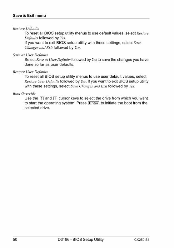
Restore Defaults To reset all BIOS setup utility menus to use default values, select Restore Defaults followed by Yes.If you want to exit BIOS setup utility with these settings, select Save Changes and Exit followed by Yes.
Save as User Defaults Select Save as User Defaults followed by Yes to save the changes you have done so far as user defaults.
Restore User Defaults To reset all BIOS setup utility menus to use user default values, select Restore User Defaults followed by Yes. If you want to exit BIOS setup utility with these settings, select Save Changes and Exit followed by Yes.
Boot Override Use the Ê and Ë cursor keys to select the drive from which you want to start the operating system. Press [Enter] to initiate the boot from the selected drive.

CX250 S1 D3196 - BIOS Setup Utility 51
10 Flash BIOS UpdateV CAUTION
If you are using the ServerView Suite you have to perform a Flash BIOS Update with Autonomous Support Packages (ASP) as described in the "Local System Update for PRIMERGY Servers" manual (on the ServerView Suite DVD 2 under Industry Standard Servers - Software - ServerView Suite - Maintenance - Update Management).
To perform a Flash BIOS update you must first download the necessary files from the internet.
V CAUTION!
The BIOS is stored in a flash memory device. If an error occurs during the Flash BIOS update procedure, the BIOS image in the flash memory may be destroyed. You can then only restore the BIOS using the Flash Memory Recovery Mode, see "Flash Memory Recovery Mode" on page 53. If this is also not possible, the flash memory device has to be replaced. Contact your customer support Service Desk. Refer to "Service Desk" leaflet for details.
I Please refer to " サポート&サービス " in a Japanese market.
Ê Preventively note down the settings in the BIOS setup utility.A Flash BIOS update does not normally affect the settings in the BIOS setup utility.
Ê Call up the following internet page: http://support.ts.fujitsu.com
I For the Japanese market please use the URL:
http://jp.fujitsu.com/platform/server/primergy/bios/
Ê Select your system via Select Product or look under Product Search by Serial-/Identnumber for your system.
Ê Click on Driver & Downloads and then select your operating system.
Ê Select Flash-BIOS.

52 D3196 - BIOS Setup Utility CX250 S1
Flash BIOS Update
Flash BIOS Update - ASP for Windows
Ê Select Flash BIOS Update - ASP for Windows.
Ê Download the file Flash BIOS CX250 S1 (ASP for Windows) for a Flash BIOS Update under Windows.
or
Ê Select Flash BIOS Update - ASP forLinux.
Ê Download the file Flash BIOS CX250 S1 (ASP for Linux) for a Flash BIOS Update under Linux.
Flash BIOS Update - USB Image
Ê If the operating system which you use is not selectable select any operating system and download the file CX250 S1 / D3196 Flash BIOS for USB Image for a Flash BIOS Update with a PC.
Flash BIOS Update under Windows or Linux
Ê Refer to "Local System Update for PRIMERGY Servers" manual for the details.
Ê After the Flash BIOS Update, please check the settings in the BIOS setup utility. If necessary, reconfigure the settings again.
Flash BIOS Update with a USB stick
Ê Make sure, that you have a bootable USB stick.
I If your USB stick is not bootable proceed as follows:
Ê The USB stick is inserted in the USB port of the system that downloads the USB image file.
Ê Follow the instructions.
You need a USB stick on which the BIOS update files will be stored. The data on the USB stick will be fully erased and overwritten.
Make sure, that all data are saved before.
Ê Unzip the downloaded zip file from CX250 S1 / D3196 Flash BIOS for USB Image.
Ê Double-click the *.exe file in the unzipped files.
CX250 S1 D3196 - BIOS Setup Utility 53
Flash BIOS Update
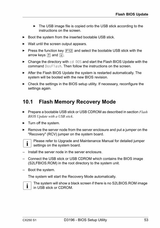
Ê The USB image file is copied onto the USB stick according to the instructions on the screen.
Ê Boot the system from the inserted bootable USB stick.
Ê Wait until the screen output appears.
Ê Press the function key [F12] and select the bootable USB stick with the arrow keys Ê and Ë.
Ê Change the directory with cd DOS and start the Flash BIOS Update with the command DosFlash. Then follow the instructions on the screen.
Ê After the Flash BIOS Update the system is restarted automatically. The system will be booted with the new BIOS revision.
Ê Check the settings in the BIOS setup utility. If necessary, reconfigure the settings again.
10.1 Flash Memory Recovery Mode
Ê Prepare a bootable USB stick or USB CDROM as described in section Flash BIOS Update with a USB stick.
Ê Turn off the system.
Ê Remove the server node from the server enclosure and put a jumper on the "Recovery" (RCV) jumper on the system board.
I Please refer to Upgrade and Maintenance Manual for detailed jumper settings on the system board.
– Install the server node in the server enclosure.
– Connect the USB stick or USB CDROM which contains the BIOS image (S2LFBIOS.ROM) in the root directory to the system unit.
– Boot the system.
The system will start the Recovery Mode automatically.
I The system will show a black screen if there is no S2LBIOS.ROM image in USB stick or CDROM.

54 D3196 - BIOS Setup Utility CX250 S1
Flash BIOS Update
The following Recovery screen is shown in BIOS setup:
Figure 9: Recovery screen
Reset NVRAMIf user wants to set BIOS settings to the default, then select Enabled. In most cases you have to keep this setting. S2LBIOS does not support BIOS setup value reservation between different versions of BIOS.
EnabledThis option resets the NVRAM to default values.
Disabled Keeps the BIOS settings if you are trying to recover BIOS with the same version.
Proceed with flash updateIf you choose Proceed with flash update the update will start.
– Observe the update process on the screen, until it is finished. The recovery update may take several minutes.

CX250 S1 D3196 - BIOS Setup Utility 55
Flash BIOS Update
Figure 10: Recovery finished
– Remove the USB stick.
– Turn off the system.
– Remove the server node from the server enclosure and remove the "Recovery" (RCV) jumper.
– Install the server node in the server enclosure.
– Turn on the system.The system will be booted with the new BIOS revision.
– Check the settings in the BIOS setup utility. If necessary, reconfigure the settings again.

56 D3196 - BIOS Setup Utility CX250 S1
Flash BIOS Update
CX250 S1 D3196 - BIOS Setup Utility 57
IndexAAccess Level 14Active Processor Cores 20Adjacent Cache Line Prefetch 21Administrator Password 48ASPM 18ATS Support 36
BBIOS Information 13BIOS setup
exiting 11menu overview 7open 9
Bits per Second 28, 31BMC firmware version 39Boot menu
open immediately 9Boot Option Priorities 45Boot Override 50Bootup NumLock State 44
CCoherency Support 35Configuration source 42Console Redirection 27, 30CSM support 44Current QPI Link Freq 36
DData Bits 28, 31DCU IP Prefetcher 22DCU Streamer Prefetcher 21Delay Time 25Device Settings 27Disable SCU devices 37Discard Changes 49Discard Changes and Exit 49DRAM RAPL BWLTMIT 35DRAM RAPL MODE 35
EEnergy Performance 23Erase SEL 42Execute Disable Bit 20
FFlow Control 29, 30, 31FRB-2 Timer 39FRB-2 Timer Policy 40FRB-2 Timer timeout 40
HHard Drive BBS Priorities 45Hardware Prefetcher 21Hyper-Threading 19
IIntel ® I/OAT 35Intel Virtualization Technology 22Intel VT-d 35IPMI version 39
LLaunch iSCSI OpROM 16Launch PXE OpROM 15Launch Storage OpROM 16Legacy OpROM Support 16Limit CPUID Maximum 20
MME subsystem 38ME update 27Memory Mode 34
NNetwork Device BBS Priorities 45NUMA 35
OO/S Watchdog Timer 40O/S Watchdog Timer Policy 41O/S Watchdog Timer Timeout 40

58 D3196 - BIOS Setup Utility CX250 S1
Index
Onboard SAS Oprom 37Out-of-Band Mgmt Port 30
PParity 29, 31PCI ROM Priority 17Perfmon and DFX devices can be
hidden or unhidden. 35Periodic SMI 37Post Report 25Power Technology 23Proceed with flash update 54Putty KeyPad 30
QQPI Link Frequency 36Quiet Boot 44
RReset NVRAM 54Restore AC Power Loss 37Restore Defaults 50Restore User Defaults 50
SSATA Mode 24SATA Port 24Save as User Defaults 50Save Changes and Reset 49Serial Port A 27Setup Prompt Timeout 43Stop Bits 29, 31Summary Screen 25Super IO Chip 26System Date 13System Time 13
TTerminal Type 28, 31
UUEFI Boot 45USB Devices 26USB Legacy Support 26User Password 48
VVT-UTF8 Combo Key Support 30
WWHEA support 19