D2.7 OAM-polarization multiphoton transfers · Sciarrino, Enrico Santamato, Lorenzo Marrucci,...
19
1 Deliverable Report Deliverable No: D2.7 Deliverable Title: OAM-polarization multiphoton transfers Grant Agreement number: 255914 Project acronym: PHORBITECH Project title: A Toolbox for Photon Orbital Angular Momentum Technology Project website address: www.phorbitech.eu Name, title and organisation of the scientific representative of deliverable’s lead beneficiary (task leader): ________________________________________________________ Dr. Fabio Sciarrino Sapienza Università di Roma Roma, Italy Deliverable table Deliverable no. D2.7 Deliverable name OAM-polarization multiphoton transfers WP no. 2 Lead beneficiary no. 2 (UROM) Nature R Dissemination level PU Delivery date from Annex I Month 24 Actual delivery date 30 September 2012
Transcript of D2.7 OAM-polarization multiphoton transfers · Sciarrino, Enrico Santamato, Lorenzo Marrucci,...

1
Deliverable Report
Deliverable No: D2.7
Deliverable Title: OAM-polarization multiphoton transfers Grant Agreement number: 255914 Project acronym: PHORBITECH Project title: A Toolbox for Photon Orbital Angular Momentum Technology Project website address: www.phorbitech.eu Name, title and organisation of the scientific representative of deliverable’s lead beneficiary (task leader): ________________________________________________________
Dr. Fabio Sciarrino Sapienza Università di Roma Roma, Italy
Deliverable table Deliverable no. D2.7 Deliverable name OAM-polarization multiphoton
transfers WP no. 2 Lead beneficiary no. 2 (UROM) Nature R Dissemination level PU Delivery date from Annex I Month 24 Actual delivery date 30 September 2012

2
D2.7) OAM-polarization multiphoton transfers: High-rate generation of OAM-entangled photon pairs exploiting spin-to-orbital conversion methods; OAM-polarization couplers for transferring quantum information from 2 photons to 1 and vice versa. OAM-polarization quantum cluster states. [Excerpt from the Annex describing the deliverables of WP2, page 16] High-rate generation of OAM-entangled photon pairs exploiting spin-to-orbital conversion methods: UROM and UNAP have realized the generation of hybrid polarization-OAM entangled states with value of OAM m up to 40 and with final measured coincidence rates up to few hundred Hz. Recently the generation of entangled states of OAM with m = 1 with a detected rate of 10 kHz has been achieved by adopting pulsed laser and q-plates with q = !. These results, although already demonstrated in the lab, have not been published yet and will be exploited in the third year of the project. OAM-polarization couplers for transferring quantum information from 2 photons to 1 and vice versa: UNAP and UROM have proposed and experimentally demonstrated a new physical process, named “quantum state fusion”, in which the two-dimensional quantum states (qubits) of two input photons are combined into a single output photon, within a four-dimensional quantum space [1]. The inverse process has been also proposed, in which the four-dimensional quantum state of a single photon is split into two photons, each carrying a qubit. Both processes can be iterated, and hence may be used to interface multi-particle protocols of quantum information with the multi-degree-of-freedom ones, with possible applications in quantum communication networks. This work has been submitted for publication and posted in arXiv [1]. The above-mentioned processes were based on a polarization-path encoding of the four-dimensional quantum state in the output photon. Hence, in order to complete the planned goal, UROM and UNAP have also conceived a scheme to perform a coherent transfer of quantum information of a hybrid ququart from the polarization-path degrees of freedom to the polarization-OAM ones and vice versa. The experiment on this last step is currently under progress and hence will be fully included in deliverable D2.10, but details about the idea are given in figures 1 and 2 of this report. Finally, the goal on the realization of polarization-OAM quantum clusters has been postponed to the third year of the project and will be reported within deliverable D2.10. Figure 1. Conceptual scheme of the optical process, here named “quantum bridge”, that converts a polarization-path hybrid encoding of ququart photon states into a polarization-OAM encoding or vice versa.
Quantum
Bridge
Hybrid
polarization-path
qu-quart
Hybrid
polarization-OAM
qu-quart

3
Figure 2. Experimental setup to demonstrate the quantum bridge device introduced in figure 1. (a) State preparation. Generation of polarization-path encoded qudit states with dimension d = 4. The input photon prepared in the |H> polarization state undergoes the transformation |H>"|k2>k|0>om # (c0|H> + c1|V>)|k2>k|0>om by means of the $rst set of waveplates (P1 and P2). Next, a calcite beam displacer separates the |H> and |V> components in two parallel paths k1 and k2, performing the transformation (c0|H> + c1|V>)|k2>k|0> om # (c0|H>"|k2>k + c1|V>|k1>k)|0>om . Finally, the set of waveplates P3-P6 performs the transformation leading to the desired final state. (b) Bridge apparatus. The " # om are implemented in a probabilistic fashion by exploiting a quarter waveplate at 45°, a q-plate with topological charge q = m/2 and a polarizing beam-splitter [E. Nagali et al., Phys. Rev. Lett. 103, 013601 (2009)]. The scheme can be also implemented deterministically by adopting the " # om transferrers reported in [V. D’Ambrosio et al., Opt. Lett. 37, 172 (2012)]. (c) Veri$cation stage. Measurement apparatus performing the analysis of the hybrid polarization-OAM output state. The upper panel corresponds to the setup for bases which are separable in the two degrees of freedoms, while the lower panel corresponds to the setup for entangled ones [see E. Nagali et al., Phys. Rev. A 81, 052317 (2010)]. PHORBITECH contribution to this deliverable PHORBITECH in this work has supported the entire cost of three post-doc fellows (Eleonora Nagali, Nicolò Spagnolo and Sergei Slussarenko) and part of the cost of the PhD students (Vincenzo D’Ambrosio, Filippo Cardano) and of the staff personnel in UROM and UNAP. Moreover, PHORBITECH, jointly with the FIRB project HYTEQ (Italian Ministry for Research), has also supported the purchase of the needed equipment and lab materials. PHORBITECH contributors to this deliverable: UROM: Nicolò Spagnolo, Chiara Vitelli, Eleonora Nagali, Vincenzo D'Ambrosio, Sandro Giacomini, Giorgio Milani, Fabio Sciarrino UNAP: Sergei Slussarenko, Filippo Cardano, Enrico Santamato, Lorenzo Marrucci Publication(s) included in this deliverable: [1] “Quantum state fusion in photons”, Chiara Vitelli, Nicolò Spagnolo, Lorenzo Aparo, Fabio Sciarrino, Enrico Santamato, Lorenzo Marrucci, submitted for publication, published online at arXiv:1209.1843.
APD calcite sm fiber
QWP HWP PBS q-plate
(a) polarization-path
state preparation(b) bridge apparatus (c) verification stage
P1P2
P3P4
P5P6
(45°)V1 V2 V3 V4 V5 V6
V4 V5 V6
V1 V2 V3
separable bases
entangled bases
π → Om
k2
k1
k1
k1
k2

Quantum state fusion in photons
Chiara Vitelli,1, 2 Nicolo Spagnolo,1 Lorenzo Aparo,1 Fabio Sciarrino,1 Enrico Santamato,3 and Lorenzo Marrucci3, 4
1Dipartimento di Fisica, Sapienza Universita di Roma, Piazzale Aldo Moro 5, I-00185 Roma, Italy2Center of Life NanoScience @ La Sapienza, Istituto Italiano di Tecnologia, Viale Regina Elena, 255, I-00185 Roma, Italy
3Dipartimento di Scienze Fisiche, Universita di Napoli “Federico II”,Complesso Universitario di Monte S. Angelo, via Cintia, 80126 Napoli, Italy
4CNR-SPIN, Complesso Universitario di Monte S. Angelo, via Cintia, 80126 Napoli, Italy
Photons are the ideal carriers of quantum information for communication. Each photon can havea single qubit or even multiple qubits encoded in its internal quantum state, as defined by opticaldegrees of freedom such as polarization, wavelength, transverse modes, etc. Here, we proposeand experimentally demonstrate a physical process, named “quantum state fusion”, in which thetwo-dimensional quantum states (qubits) of two input photons are combined into a single outputphoton, within a four-dimensional quantum space. The inverse process is also proposed, in whichthe four-dimensional quantum state of a single photon is split into two photons, each carrying aqubit. Both processes can be iterated, and hence may be used to bridge multi-particle protocols ofquantum information with the multi-degree-of-freedom ones, with possible applications in quantumcommunication networks.
The emerging field of quantum information technol-ogy is based on our ability to manipulate and transmitthe internal quantum states of physical systems, suchas photons, ions, atoms, superconducting circuits, etc.[1, 2]. In photonic approaches [3, 4], much research ef-fort has been recently devoted to expanding the usefulquantum space by two alternative approaches: either byincreasing the number of involved photons [5] or by ex-ploiting different degrees of freedom of the same photon,such as polarization, time-bin, wavelength, propagationpaths, and orbital angular momentum [6–16]. Hitherto,however, these two approaches have proceeded parallel toeach other, with little or no attempt at combining them.In this paper, we introduce and prove the realizability oftwo novel quantum-state manipulation processes, namelyfusion and fission, that can be used to bridge these twoapproaches, allowing for their full integration. Some pos-sible specific applications will be discussed in the conclud-ing paragraphs of this paper.
Quantum state fusion is here defined as the physi-cal process by which the internal quantum state of twoparticles (e.g., photons) is transferred into the four-dimensional internal quantum state of a single particle(photon). In the language of quantum information, twoarbitrary input qubits initially attached to separate par-ticles are transferred into a single particle, where theyare encoded exploiting at least four independent statesof the same particle (i.e., a single-particle “qudit”). Inthis framework, this process may also be called “quan-tum information fusion” or “qubit fusion”. For example,let us assume that initially we have two photons, labeled1 and 2, having independent polarization quantum states(i.e., carrying polarization-encoded qubits), as follows:
|ψ�1 = α|H�1 + β|V �1|φ�2 = γ|H�2 + δ|V �2 (1)
where H and V denote the horizontal and vertical linearpolarizations, respectively. The initial two-photon state
can then be written as the product
|Ψ�12 = (α|H�1 + β|V �1)⊗ (γ|H�2 + δ|V �2)= αγ|H�1|H�2 + αδ|H�1|V �2 + βγ|V �1|H�2
+βδ|V �1|V �2
The quantum state fusion corresponds to transformingthis state into the same linear combination of four or-thogonal single particle states of the outgoing photon 3:
|Ψ�12 → |Ψ�3 = αγ|0�3 + αδ|1�3 + βγ|2�3 + βδ|3�3 (2)
where |0�, |1�, |2�, |3� denote four orthogonal internalstates of the photon. These four states can be used to de-fine a four-dimensional logical basis of a “qudit” carriedby the photon. Of course we cannot use the sole two-dimensional polarization space for the outgoing photon.One possibility is to use four independent spatial modesor, alternatively, two spatial modes combined with thetwo polarizations. Figure 1a graphically illustrates thequantum fusion concept.
More generally, the fusion process should work evenfor entangled quantum states, both internally entangled(i.e., the two particles are entangled with each other) andexternally entangled (the two particles are entangled withother particles). In the first case, the four coefficients ob-tained in the tensor product αγ,αδ,βγ,βδ are replacedwith four arbitrary coefficients α0,α1,α2,α3. In the sec-ond case, the four coefficients are replaced with four ketsrepresenting different quantum states of the external en-tangled system.
It should be noted that in terms of information content,the quantum fusion has no effect: we have two qubits ini-tially and the same two qubits at the end. In other words,state fusion is not a quantum logical gate for informationprocessing (and it should not be confused with the fusiongate used to create quantum clusters, see e.g. [17]). How-ever, physically there is an important transformation, asthe two qubits are moved from two separate particles into
arX
iv:1
209.
1843
v2 [
quan
t-ph]
17
Sep
2012

2
FIG. 1. Quantum state fusion. (a) Concept: inputphotons 1 and 2, each carrying a single qubit in their two-dimensional internal states (shown as red and green circles),are merged into output photon 3, carrying both qubits in itsfour-dimensional internal space. (b) Implementation schemebased on CNOT gates. |ψ� and |φ� denote the qubit statesof the two input photons. |ψ� ⊗ |φ� denotes the 2-qubit stateof the outgoing photon, conditional on detection of one out-put photon in the logical-zero output port of the Hadamardgate (H). c and t denote the control and target ports of theCNOT gates. (c) Inverse scheme for quantum state fission.|10� denotes the state of an auxiliary input photon that is lo-calized in the upper mode, corresponding to logical-zero. Theprocess success is conditional on detecting no photon in thelogical-one output of the two H gates.
a single one. This is analogous to what occurs in quan-tum teleportation, in which the information content isunchanged, but there is a physical transformation in theinformation localization [18–20].
To be useful in the quantum information field, the pro-cess of qubit fusion ideally should be also “iterable”, i.e.it should be possible to keep adding qubits to the sameparticle by using a larger and larger internal space. More-over, the process should be “invertible”, i.e. one shouldbe able to split a higher-dimensional quantum state of aparticle into two (or more) particles. We will name thisinverse process “quantum state fission”.
The feasibility of quantum state fusion and fission inphotons is a question of clear fundamental interest, be-cause photons do not interact, or interact very weakly innonlinear media. Therefore, there is no straightforwardway to transfer the quantum state from one photon to theother. The solution we adopt here is based on the Knill-Laflamme-Milburn (KLM) approach to quantum compu-tation with linear optics [17, 21]. A qubit transfer froma particle carrier to another can be generally realizedby the application of a single controlled-NOT (CNOT)logical gate. The source qubit in state α|0�c + β|1�c
is used as control (hence the label c) and the destina-tion qubit as target, which is initialized to the logicalzero |0�t. After the CNOT, the two qubits are entangledin state α|0�c|0�t + β|1�c|1�t. A subsequent erasing ofqubit c by projection on an unbiased linear combinationstate |+�c = (|0�c + |1�c)/
√2 completes the transfer of
the quantum state in the qubit t. In the case of fusion,however, we have the additional complication that thedestination carrier photon also transports another qubitwhich must not be altered in the CNOT process. SinceKLM gates are all based on two-photon interference (i.e.the Hong-Ou-Mandel effect, HOM [22]), the presence ofthe additional qubit makes the two photons partially dis-tinguishable and hence disrupts the gate workings.
The solution we found to this problem is based on thetrick of initially “unfolding” the qubit to be preservedinto the superposition of two zero-initialized qubits andthen acting on both qubits with a CNOT gate using thesame control, as illustrated in Fig. 1b. In this figure, eachline represents a possible photonic (spatial and/or polar-ization) mode, so that a qubit is represented by two lines(this is a “path” or “dual-rail” encoding of the qubits).We adopt the photon-number notation in order to beable to describe also “empty” qubits, i.e., vacuum states,which do occur in the fusion protocol. Given two modesforming a qubit, the |10� ket, where the 0s and 1s re-fer here to the photon numbers, corresponds to havinga photon in the first mode, encoding the logical 0 of thequbit. The |01� ket will then represent the photon in thesecond path, encoding the logical 1 of the qubit. We willalso need the |00� ket, representing a vacuum state, i.e.the “empty” qubit.
The two photons whose state is to be merged travel intwo pairs of modes that we will label as c and t, with ref-erence to the CNOT input qubits. The initial state of thetwo photons is taken to be the following (for simplicitywe consider the case of two independent input states, butthe results are valid also in the more general entangledcase):
|ψ�t = α|10�t + β|01�t|φ�c = γ|10�c + δ|01�c (3)
The qubit “unfolding” corresponds to adding two emptymodes for photon t and rearranging the four modes so asto obtain the following state:
|ψ�t = α|1000�t + β|0010�t (4)
The first two t modes are then treated as one qubit (t1)and the final two t modes as a second qubit (t2), both ofthem initialized to logical zero, but with the possibilityfor each of them to be actually empty. Each of thesequbits is then subjected to a CNOT with the same c
qubit, and finally the c qubit is erased by projection onthe |+� state (this corresponds to applying a Hadamardgate and detecting a logical zero). A simple calculation(see Supplementary Materials) shows that this procedure

3
FIG. 2. Schematics of the photon quantum fusion ap-paratus. Each red line in this scheme is an optical spatialmode, corresponding to two possible photonic states given byorthogonal polarizations. The input photon quantum statesare polarization-encoded (horizontal H and vertical V linearpolarizations, corresponding to logical 0 and 1 of photonicqubits, respectively) and travel in spatial modes c (control)and t (target). The ancilla photon must enter the setup inthe H polarization state along mode a. The output photon“fused” quantum state lives in a Hilbert space obtained bycombining the two spatial modes t1 and t2 and the two po-larizations. The PBSs are assumed to transmit the H polar-ization and reflect the V one. The intermediate and outputmodes are given the same label in the transmission througheach optical component, except for the unfolding step, real-ized by PBSt, which splits mode t into modes t1 and t2. HWPsoriented at 22.5◦ implement Hadamard gates in the polariza-tion space. The blue-colored HWP is oriented at −22.5◦ soas to be equivalent to a σx gate followed by a Hadamard one.PBSca copies the c photon state onto the ancilla, while PBSat
and PBSct implement the two CNOT gates. Single photon de-tectors (D) are used to filter the useful output. The fusion issuccessful if the output c and a photons are both detected inthe H channel and there is one and only one photon in eachoutput channel (c, a, t), an event which occurs with a proba-bility of 1/32. By exploiting all four possible cases in the a
and c polarization detection and a suitable feed-forward, thesuccess probability can be raised to 1/8.
brings the target photon into the desired “fused” state
|Ψ�t = (|ψ� ⊗ |φ�)t = αγ|1000�t + αδ|0100�t+βγ|0010�t + βδ|0001�t. (5)
Since the c qubit measurement has a probability of 50% of
obtaining |+�, the described method is probabilistic, witha success probability of 50% (not considering the CNOTsuccess probability). However, the probability can beraised to 100% by a simple feed-forward procedure, i.e.by applying a suitable unitary transformation on the t
photon if the c measurement yields the orthogonal state|−� = (|0� − |1�)/
√2.
One key aspect of the illustrated method is that, af-ter unfolding, each CNOT works with a target photonthat carries no additional information, so that interfer-ence effects are not disrupted. On the other hand, theCNOT gates must work properly also in the case of emptytarget qubits, in which case the CNOT must return anunmodified quantum state (see Supplementary Materi-als for details). This is a non-trivial requirement, notauthomatically guaranteed for all KLM approaches, par-ticularly when two CNOTs are used in series, as in thepresent case.It can be readily seen that the procedure we have de-
scribed can be also iterated for merging additional qubitsto the same photon. For example, in order to add athird qubit, we only need to insert four additional vac-uum modes of the target, organized in four pairs so thatall components carrying a nonzero amplitude correspondto the logical 0s of the qubits. Next, we need to performfour CNOT operations always using as control qubit thenew qubit to be merged. Finally, we erase the controland leave the eight modes of the target qubit represent-ing the three qubits. And so on. The inverse operation ofquantum state fission can be also implemented in a verysimilar way to the fusion, as shown in Fig. 1c. Furtherdetails about this scheme are given in the SupplementaryMaterials.Let us now consider a specific demonstrative imple-
mentation of the fusion scheme using linear optics, ina KLM approach [21]. CNOTs can be implemented inlinear optics only probabilistically, although in principlethe probability can be made as high as desired by intro-ducing an increasing number of ancilla photons. In ourimplementation, which uses polarization-encoded qubits,we use the CNOT schemes proposed by Pittman et al.,based on half-wave plates (HWP) and polarizing beam-splitters (PBS) [23–26]. Since the c photon must finallybe erased, we can use a single photon ancilla for bothgates, and the whole scheme becomes actually symmet-rical for the exchange of the two CNOTs. The overall fu-sion scheme, shown in Fig. 5, thus requires three photonsonly, the two to be merged and the ancilla. Its theoreticalsuccess probability is 1/32 without feed-forward and 1/8with feed-forward and it does not rely on post-selection.The full quantum analysis of this scheme is reported inthe Supplementary Materials.The experimental apparatus is shown in Fig. 3. The
measurements are based on detecting the fourfold co-incidences of the trigger and the output modes a, c, t.For testing the fusion apparatus, we performed quan-tum fusion of c and t photons prepared either in thelogical-basis polarization states |H�, |V � or in their su-

4
FIG. 3. Experimental setup for implementing and testing the quantum-state fusion. (a) Optical source usedfor generating the three input photons. Spontaneous parametric down-conversion (PDC) in a 1.5-mm-thick β-barium boratecrystal (BBO) cut for type-II phase matching, pumped by the second harmonic (SHG) of a Ti:Sa mode-locked laser, generatestwo polarization-entangled photon pairs at 795 nm (filtered to 3-nm bandwidth) in modes k1 and k2 [30]. Each mode is thensplit by a PBS. One of the four photons is immediately detected by an avalanche photodiode (APD) and used as trigger. Theother three are spatially filtered by coupling through single-mode (SM) fibers, have their polarization set by HWPs, and enterthe fusion setup along input modes a, c, t. (b) Fusion setup, corresponding to the layout shown in Fig. 5. To ensure greaterphase stability, the unfolding PBSt is implemented with a 4-cm-long calcite crystal, so as to obtain two close parallel pathsand to use a single PBSact in the place of PBSct and PBSat. Delay lines were used for the time superposition of the photonsin the PBSs. (c) Verification stage, used for analyzing the output photon state. The analysis in polarization is made with aHWP and a PBS. Superpositions of modes t1 and t2 were then detected by recombining the two modes in a second calcitecrystal and then analyzing again in polarization (this step was not needed for pure t1 or t2 modes). (d) Legend of opticalelements. Single-photon count rates were 20-100 kHz, double-concidence rates 200-1000 Hz, and fourfold coincidences few perhour. The degree of photon indistinguishability was quantified via HOM dip visibility [22]: we obtained 0.94±0.01 for photonpairs generated in orthogonal polarization states in modes k1 and k2 (belonging to the same PDC pair) and 0.75±0.05 forphotons having the same polarization (different PDC pairs).
perposition basis states |+�, |−�. The experimental re-sults are shown in the upper panels of Fig. 4. For eachexperimental run, a given state of the two input pho-tons was prepared and the final four-dimensional stateof the output photon was measured, by projection onall four basis states belonging to the expected fusionbasis (see caption of Fig. 4). Ideally, we should findnonzero coincidences only when the detected state isthe expected “fused” one, corresponding to a unitaryfidelity. The measured experimental fidelity, averaged
over all tested states, was instead F = (75.0 ± 1.3)%.The average measured fidelities for each tested basis areshown in the Supplementary Materials. All experimen-tal fidelities, both averaged and individual-state ones, arefound to be well above the 40% state-estimation maxi-mal fidelity for a four-dimensional quantum state, show-ing that our fusion apparatus works much better thana measure-and-prepare trivial approach. Moreover, wecould explain quantitatively the non-unitary observed fi-delities by considering the fact that the PDC process
5
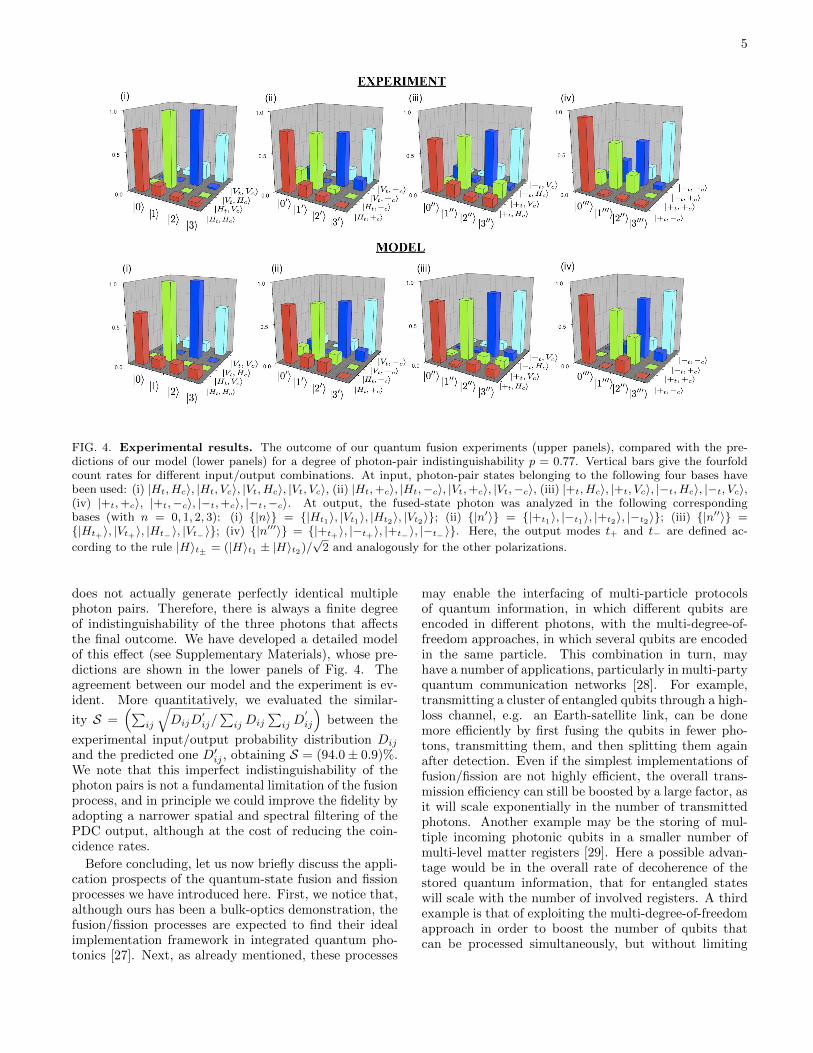
FIG. 4. Experimental results. The outcome of our quantum fusion experiments (upper panels), compared with the pre-dictions of our model (lower panels) for a degree of photon-pair indistinguishability p = 0.77. Vertical bars give the fourfoldcount rates for different input/output combinations. At input, photon-pair states belonging to the following four bases havebeen used: (i) |Ht, Hc�, |Ht, Vc�, |Vt, Hc�, |Vt, Vc�, (ii) |Ht,+c�, |Ht,−c�, |Vt,+c�, |Vt,−c�, (iii) |+t, Hc�, |+t, Vc�, |−t, Hc�, |−t, Vc�,(iv) |+t,+c�, |+t,−c�, |−t,+c�, |−t,−c�. At output, the fused-state photon was analyzed in the following correspondingbases (with n = 0, 1, 2, 3): (i) {|n�} = {|Ht1�, |Vt1�, |Ht2�, |Vt2�}; (ii) {|n��} = {|+t1�, |−t1�, |+t2�, |−t2�}; (iii) {|n���} ={|Ht+�, |Vt+�, |Ht−�, |Vt−�}; (iv) {|n����} = {|+t+�, |−t+�, |+t−�, |−t−�}. Here, the output modes t+ and t− are defined ac-
cording to the rule |H�t± = (|H�t1 ± |H�t2)/√2 and analogously for the other polarizations.
does not actually generate perfectly identical multiplephoton pairs. Therefore, there is always a finite degreeof indistinguishability of the three photons that affectsthe final outcome. We have developed a detailed modelof this effect (see Supplementary Materials), whose pre-dictions are shown in the lower panels of Fig. 4. Theagreement between our model and the experiment is ev-ident. More quantitatively, we evaluated the similar-
ity S =��
ij
�DijD
�ij/�
ijDij
�ijD
�
ij
�between the
experimental input/output probability distribution Dij
and the predicted one D�ij, obtaining S = (94.0± 0.9)%.
We note that this imperfect indistinguishability of thephoton pairs is not a fundamental limitation of the fusionprocess, and in principle we could improve the fidelity byadopting a narrower spatial and spectral filtering of thePDC output, although at the cost of reducing the coin-cidence rates.
Before concluding, let us now briefly discuss the appli-cation prospects of the quantum-state fusion and fissionprocesses we have introduced here. First, we notice that,although ours has been a bulk-optics demonstration, thefusion/fission processes are expected to find their idealimplementation framework in integrated quantum pho-tonics [27]. Next, as already mentioned, these processes
may enable the interfacing of multi-particle protocolsof quantum information, in which different qubits areencoded in different photons, with the multi-degree-of-freedom approaches, in which several qubits are encodedin the same particle. This combination in turn, mayhave a number of applications, particularly in multi-partyquantum communication networks [28]. For example,transmitting a cluster of entangled qubits through a high-loss channel, e.g. an Earth-satellite link, can be donemore efficiently by first fusing the qubits in fewer pho-tons, transmitting them, and then splitting them againafter detection. Even if the simplest implementations offusion/fission are not highly efficient, the overall trans-mission efficiency can still be boosted by a large factor, asit will scale exponentially in the number of transmittedphotons. Another example may be the storing of mul-tiple incoming photonic qubits in a smaller number ofmulti-level matter registers [29]. Here a possible advan-tage would be in the overall rate of decoherence of thestored quantum information, that for entangled stateswill scale with the number of involved registers. A thirdexample is that of exploiting the multi-degree-of-freedomapproach in order to boost the number of qubits thatcan be processed simultaneously, but without limiting

6
the possibility of interacting with separate parties for thequbit input/output. We also envision many interestingapplications in the study of fundamental issues in quan-tum physics. For example, by exploiting the possibility
of fusing states that are entangled with external systemsone may create and study complex many-particle clustersof entangled states.
[1] C. H. Bennett and D. P. DiVincenzo, “Quantum infor-mation and computation,” Nature 404, 247–255 (2000).
[2] T. D. Ladd, F. Jelezko, R. Laflamme, Y. Nakamura,C. Monroe, and J. L. O’Brien, “Quantum computers,”Nature 464, 45–53 (2010).
[3] J. L. O’Brien, A. Furusawa, and J. Vuckovic, “Photonicquantum technologies,” Nat. Photon. 3, 687–695 (2009).
[4] J.-W. Pan, Z.-B. Chen, C.-Y. Lu, H. Weinfurter,A. Zeilinger, and M. Zukowski, “Multiphoton entangle-ment and interferometry,” Rev. Mod. Phys. 84, 777–838(2012).
[5] X.-C. Yao, T.-X. Wang, P. Xu, H. Lu, G.-S. Pan, X.-H. Bao, C.-Z. Peng, C.-Y. Lu, Y.-A. Chen, and J.-W.Pan, “Observation of eight-photon entanglement,” Nat.Photon. 6, 225–228 (2012).
[6] A. Mair, V. Alipasha, G. Weihs, and A. Zeilinger, “En-tanglement of the orbital angular momentum states ofphotons,” Nature 412, 313–316 (2001).
[7] J. T. Barreiro, N. K. Langford, N. A. Peters, and P. G.Kwiat, “Generation of hyperentangled photon pairs,”Phys. Rev. Lett. 95, 260501 (2005).
[8] G. Molina-Terriza, J. P. Torres, and L. Torner, “Twistedphotons,” Nat. Phys. 3, 305–310 (2007).
[9] B. P. Lanyon, M. Barbieri, M. P. Almeida, T. Jennewein,T. C. Ralph, K. J. Resch, G. J. Pryde, J. L. O’Brien,A. Gilchrist, and A. G. White, “Simplifying quantumlogic using higher-dimensional hilbert spaces,” Nat. Phys.5, 134–140 (2009).
[10] R. Ceccarelli, G. Vallone, F. De Martini, P. Mataloni,and A. Cabello, “Experimental entanglement and non-locality of a two-photon six-qubit cluster state,” Phys.Rev. Lett. 103, 160401 (2009).
[11] E. Nagali, L. Sansoni, L. Marrucci, E. Santamato, andF. Sciarrino, “Experimental generation and characteri-zation of single-photon hybrid ququarts based on polar-ization and orbital angular momentum encoding,” Phys.Rev. A 81, 052317 (2010).
[12] S. Straupe and S. Kulik, “Quantum optics: The quest forhigher dimensionality,” Nat. Photon. 4, 585–586 (2010).
[13] E. Nagali, D. Giovannini, L. Marrucci, S. Slussarenko,E. Santamato, and F. Sciarrino, “Experimental optimalcloning of four-dimensional quantum states of photons,”Phys. Rev. Lett. 105, 73602 (2010).
[14] W.-B. Gao, C.-Y. Lu, X.-C. Yao, P. Xu, O. Guhne,A. Goebel, Y.-A. Chen, C.-Z. Peng, Z.-B. Chen, andJ.-W. Pan, “Experimental demonstration of a hyper-entangled ten-qubit schrodinger cat state,” Nat. Phys.6, 331–335 (2010).
[15] D. Pile, “How many bits can a photon carry?” Nat. Pho-ton. 6, 14–15 (2011).
[16] A. C. Dada, J. Leach, G. S. Buller, M. J. Padgett,and E. Andersson, “Experimental high-dimensional two-photon entanglement and violations of generalized bellinequalities,” Nat. Phys. 7, 677–680 (2011).
[17] P. Kok, W. J. Munro, K. Nemoto, T. C. Ralph, J. P.
Dowling, and G. J. Milburn, “Linear optical quantumcomputing with photonic qubits,” Rev. Mod. Phys. 79,135–174 (2007).
[18] C. H. Bennett, G. Brassard, C. Crepeau, R. Jozsa,A. Peres, and W. K. Wootters, “Teleporting an unknownquantum state via dual classical and Einstein-Podolsky-Rosen channels,” Phys. Rev. Lett. 70, 1895–1899 (1993).
[19] D. Bouwmeester, J. W. Pan, K. Mattle, M. Eibl, H. We-infurter, and A. Zeilinger, “Experimental quantum tele-portation,” Nature 390, 575–579 (1997).
[20] D. Boschi, S. Branca, F. De Martini, L. Hardy, andS. Popescu, “Experimental realization of teleporting anunknown pure quantum state via dual classical andEinstein-Podolsky-Rosen channels,” Phys. Rev. Lett. 80,1121–1125 (1998).
[21] E. Knill, R. Laflamme, and G. J. Milburn, “A schemefor efficient quantum computation with linear optics,”Nature 409, 46–52 (2001).
[22] C. K. Hong, Z. Y. Ou, and L. Mandel, “Measurementof subpicosecond time intervals between two photons byinterference,” Phys. Rev. Lett. 59, 2044–2046 (1987).
[23] T. B. Pittman, B. C. Jacobs, and J. D. Franson, “Prob-abilistic quantum logic operations using polarizing beamsplitters,” Phys. Rev. A 64, 062311 (2001).
[24] T. B. Pittman, M. J. Fitch, B. C. Jacobs, and J. D.Franson, “Experimental controlled-not logic gate for sin-gle photons in the coincidence basis,” Phys. Rev. A 68,032316 (2003).
[25] S. Gasparoni, J.-W. Pan, P. Walther, T. Rudolph, andA. Zeilinger, “Realization of a photonic controlled-notgate sufficient for quantum computation,” Phys. Rev.Lett. 93, 020504 (2004).
[26] Z. Zhao, A.-N. Zhang, Y.-A. Chen, H. Zhang, J.-F. Du,T. Yang, and J.-W. Pan, “Experimental demonstrationof a nondestructive controlled-not quantum gate for twoindependent photon qubits,” Phys. Rev. Lett. 94, 030501(2005).
[27] L. Sansoni, F. Sciarrino, G. Vallone, P. Mataloni,A. Crespi, R. Ramponi, and R. Osellame, “Polariza-tion entangled state measurement on a chip,” Phys. Rev.Lett. 105 (2010).
[28] H. J. Kimble, “The quantum internet,” Nature 453,1023–1030 (2008).
[29] B. Julsgaard, J. Sherson, J. I. Cirac, J. Fiurasek, andE. S. Polzik, “Experimental demonstration of quantummemory for light,” Nature 432, 482–486 (2004).
[30] M. Eibl, S. Gaertner, M. Bourennane, C. Kurtsiefer,M. Zukowski, and H. Weinfurter, “Experimental ob-servation of four-photon entanglement from parametricdown-conversion,” Phys. Rev. Lett. 90, 200403 (2003).
[31] K. Tsujino, H. F. Hofmann, S. Takeuchi, and K.Sasaki, “Distinguishing genuine entangled two-photon-polarization states from independently generated pairs ofentangled photons”, Phys. Rev. Lett. 92, 153602 (2004).

7
Supplementary Materials accompanies thismanuscript.
Acknowledgments. This work was supported bythe Future Emerging Technologies FET-Open Program,within the 7th Framework Programme of the EuropeanCommission, under Grant No. 255914, PHORBITECH,and by FIRB-Futuro in Ricerca HYTEQ.
Author Contributions. L.M., with contributions fromF.S. and E.S., conceived the qubit fusion/fission conceptand the corresponding optical schemes. C.V., N.S., andF.S. designed the experimental layout and methodologyand, with L.A., carried out the experiments. N.S., C.V.,and F.S. developed the model of partial photon distin-guishability. All authors discussed the results and par-ticipated in drawing up the manuscript.
Author Information. The authors declare nocompeting financial interests. Correspondenceand requests for materials should be addressedto L.M. ([email protected]) or to F.S.([email protected]).
8
SUPPLEMENTARY MATERIALS
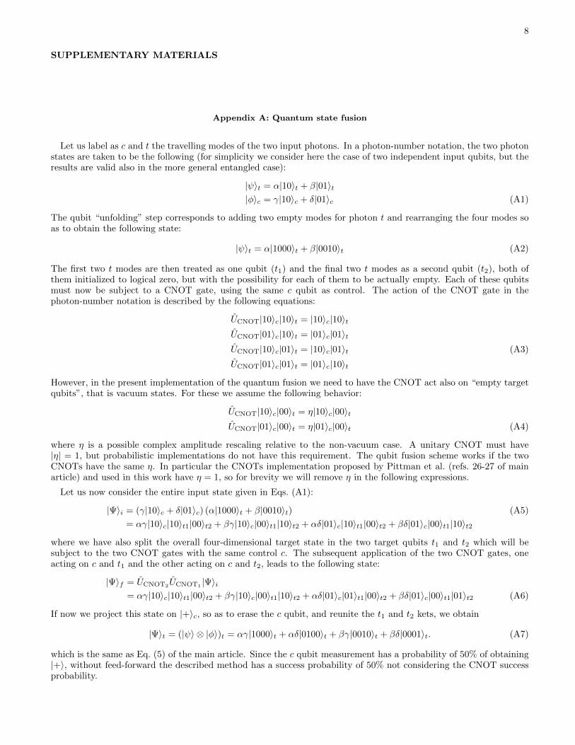
Appendix A: Quantum state fusion
Let us label as c and t the travelling modes of the two input photons. In a photon-number notation, the two photonstates are taken to be the following (for simplicity we consider here the case of two independent input qubits, but theresults are valid also in the more general entangled case):
|ψ�t = α|10�t + β|01�t|φ�c = γ|10�c + δ|01�c (A1)
The qubit “unfolding” step corresponds to adding two empty modes for photon t and rearranging the four modes soas to obtain the following state:
|ψ�t = α|1000�t + β|0010�t (A2)
The first two t modes are then treated as one qubit (t1) and the final two t modes as a second qubit (t2), both ofthem initialized to logical zero, but with the possibility for each of them to be actually empty. Each of these qubitsmust now be subject to a CNOT gate, using the same c qubit as control. The action of the CNOT gate in thephoton-number notation is described by the following equations:
UCNOT|10�c|10�t = |10�c|10�tUCNOT|01�c|10�t = |01�c|01�tUCNOT|10�c|01�t = |10�c|01�t (A3)
UCNOT|01�c|01�t = |01�c|10�t
However, in the present implementation of the quantum fusion we need to have the CNOT act also on “empty targetqubits”, that is vacuum states. For these we assume the following behavior:
UCNOT|10�c|00�t = η|10�c|00�tUCNOT|01�c|00�t = η|01�c|00�t (A4)
where η is a possible complex amplitude rescaling relative to the non-vacuum case. A unitary CNOT must have|η| = 1, but probabilistic implementations do not have this requirement. The qubit fusion scheme works if the twoCNOTs have the same η. In particular the CNOTs implementation proposed by Pittman et al. (refs. 26-27 of mainarticle) and used in this work have η = 1, so for brevity we will remove η in the following expressions.
Let us now consider the entire input state given in Eqs. (A1):
|Ψ�i = (γ|10�c + δ|01�c) (α|1000�t + β|0010�t) (A5)
= αγ|10�c|10�t1|00�t2 + βγ|10�c|00�t1|10�t2 + αδ|01�c|10�t1|00�t2 + βδ|01�c|00�t1|10�t2
where we have also split the overall four-dimensional target state in the two target qubits t1 and t2 which will besubject to the two CNOT gates with the same control c. The subsequent application of the two CNOT gates, oneacting on c and t1 and the other acting on c and t2, leads to the following state:
|Ψ�f = UCNOT2UCNOT1 |Ψ�i= αγ|10�c|10�t1|00�t2 + βγ|10�c|00�t1|10�t2 + αδ|01�c|01�t1|00�t2 + βδ|01�c|00�t1|01�t2 (A6)
If now we project this state on |+�c, so as to erase the c qubit, and reunite the t1 and t2 kets, we obtain
|Ψ�t = (|ψ� ⊗ |φ�)t = αγ|1000�t + αδ|0100�t + βγ|0010�t + βδ|0001�t. (A7)
which is the same as Eq. (5) of the main article. Since the c qubit measurement has a probability of 50% of obtaining|+�, without feed-forward the described method has a success probability of 50% not considering the CNOT successprobability.

9
If the outcome of the c measurement is |−�c, we obtain the following target state:
|Ψ�t = αγ|1000�t − αδ|0100�t + βγ|0010�t − βδ|0001�t. (A8)
This state can be transformed back into Eq. (A7) by a suitable unitary transformaton. Therefore, the successprobability of the fusion scheme can be raised to 100% (again not considering CNOTs success probabilities) by afeed-forward mechanism.
Appendix B: Quantum state fusion setup: full calculation
In this section, the quantum process taking place in the quantum fusion setup is calculated step by step, consideringthe ideal case of perfectly identical photons. In a following Section, we will consider also the effect of a partialdistinguishability of the photons.
The optical layout is shown in figure 5 (or Fig. 2 of the main text). We label as c and t the input modes of thetwo photons to be fused and a the ancilla photon mode. By convention, the intermediate and output modes in thesetup are given the same label in the parallel transmission through optical components, except for the unfoldingstep which splits mode t into modes t1 and t2. The input qubits are polarization-encoded photons, with horizontalH and vertical V linear polarizations standing for logical 0 and 1, respectively. The output “fused” photon will befinally encoded in two spatial modes, t1 and t2, and the corresponding H,V polarization modes. The polarizing beamsplitters (PBS) are assumed to transmit the H polarization and reflect the V one and not to introduce a phase shiftbetween the two components (a real PBS may possibly introduce a phase shift, but this can be always compensatedwith suitable birefringent plates, as was actually done in our experiment). The ancilla photon must enter the setupin the H polarization state. The half-wave plates (HWP) are all oriented at 22.5◦ with respect to the H direction,so as to act as Hadamard gates [H → (H + V )/
√2, V → (H − V )/
√2], except for the (yellow-colored in the figure)
one located after the unfolding PBS along the t2 output mode, which is oriented at −22.5◦, so as to perform thetransformation V → (H + V )/
√2.
Let us now calculate the behavior of our fusion apparatus. The three-photon input state is the following:
|Ψi� = (α0HtHc + α1HtVc + α2VtHc + α3VtVc)Ha (B1)
where in the right-hand-side we omit the ket symbols for brevity and we have assumed the c and t photons to be inan arbitrary two-photon state, either separable or entangled. In particular, the case of separable qubits considered inthe main article corresponds to setting α0 = αγ,α1 = αδ,α2 = βγ,α3 = βδ, where (α,β) and (γ, δ) are the coefficientpairs defining the two qubit states. As we shall see below, the symbols H and V should be actually taken to representthe photon creation operators (for the given polarization and spatial mode) to be applied to the vacuum state, inorder to obtain the resulting ket state. The creation-operator interpretation is needed for the states involving two ormore photons in a same mode, which in our case appear only as intermediate states but not in the final output.
We now consider the effect of each optical component in sequence, indicating as subscript(s) the mode(s) on whichthe optical component is acting:
HWPa−−−−→ (α0HtHc + α1HtVc + α2VtHc + α3VtVc)1√2(Ha + Va)
PBSa,c−−−−→ 1√2[(α0Ht + α2Vt)HcHa + (α1Ht + α3Vt)VcVa + (α1Ht + α3Vt)HaVa + (α0Ht + α2Vt)HcVc)]
HWPaHWPc−−−−−−−−→ 1
2√2[(α0Ht + α2Vt)(Hc + Vc)(Ha + Va) + (α1Ht + α3Vt)(Hc − Vc)(Ha − Va)
+(α1Ht + α3Vt)(H2a− V
2a) + (α0Ht + α2Vt)(H
2c− V
2c)]
where in the last expression, we introduced the squared symbols H2 or V
2 to denote a two-photon state for thegiven mode (the precise normalization convention here corresponds to considering the H and V symbols as creationoperators for the given mode acting on vacuum, or equivalently to setting H
2 =√2|2�H in the photon-number ket

10
FIG. 5. Schematics of the quantum fusion apparatus (this figure is equivalent to Fig. 2 of the main manuscript and isrepeated here for the reader convenience). Each red line in this scheme is a photonic spatial mode, corresponding to twopossible photonic states given by orthogonal polarizations. Polarizing beam-splitters (PBS) are indicated by barred squaresand assumed to transmit horizontal and reflect vertical polarizations; half-wave plates (HWP) are indicated by thin rectanglesand are all oriented at 22.5◦ so as to implement Hadamard gates in the polarization space, except for the yellow-colored onewhich is oriented at −22.5◦ so as to be equivalent to a NOT gate followed by the Hadamard one; single photon detectors (D)are used to filter the useful output.
notation, and similar). Continuing with the unfolding step in the t mode:
PBSt−−−→ 1
2√2[(α0Ht1 + α2Vt2)(Hc + Vc)(Ha + Va) + (α1Ht1 + α3Vt2)(Hc − Vc)(Ha − Va)
+(α1Ht1 + α3Vt2)(H2a− V
2a) + (α0Ht1 + α2Vt2)(H
2c− V
2c)]
Note that the absence of a symbol for a given mode in a term corresponds to having the vacuum state in that mode(this again corresponds to the creation-operator notation). Next, we have
HWPt1HWPt2−−−−−−−−−→1
4[(α0Ht1 + α0Vt1 + α2Ht2 + α2Vt2)(Hc + Vc)(Ha + Va)
+(α1Ht1 + α1Vt1 + α3Ht2 + α3Vt2)(Hc − Vc)(Ha − Va)
+(α1Ht1 + α1Vt1 + α3Ht2 + α3Vt2)(H2a− V
2a) + (α0Ht1 + α0Vt1 + α2Ht2 + α2Vt2)(H
2c− V
2c)]
Let us now consider the effect of each of the two PBS acting as CNOTs. We will also drop all terms which do not leadto one (and only one) output photon in each of the two modes c and a. The latter is a projection step (PS) ensuredby the final photon detection. We thus obtain
PBSa,t1PSa−−−−−−−−→1
4[(α0Ht1Ha + α0Vt1Va + α2Ht2Ha + α2Vt2Ha)(Hc + Vc)
+(α1Ht1Ha − α1Vt1Va + α3Ht2Ha + α3Vt2Ha)(Hc − Vc) + α0Va(H2c− V
2c)]
PBSc,t2PSc−−−−−−−→1
4(α0Ht1HaHc + α0Vt1VaHc + α2Ht2HaHc + α2Vt2HaVc + α1Ht1HaHc − α1Vt1VaHc
+α3Ht2HaHc − α3Vt2HaVc)

11
and finally all the exit half-wave plates:
HWPaHWPcHWPt1HWPt2−−−−−−−−−−−−−−−−−−→ 1
8√2[(α0+α1)(Ht1 + Vt1)(Ha + Va)(Hc + Vc) + (α0−α1)(Ht1 − Vt1)(Ha − Va)(Hc + Vc)
+(α2+α3)(Ht2 + Vt2)(Ha + Va)(Hc + Vc) + (α2−α3)(Ht2 − Vt2)(Ha + Va)(Hc − Vc)
By expanding the products, we obtain the following final state:
|Ψf � =HaHc
4√2(α0Ht1 + α1Vt1 + α2Ht2 + α3Vt2) +
HaVc
4√2(α0Ht1 + α1Vt1 + α2Vt2 + α3Ht2)
+VaHc
4√2(α0Vt1 + α1Ht1 + α2Ht2 + α3Vt2) +
VaVc
4√2(α0Vt1 + α1Ht1 + α2Vt2 + α3Ht2)
It is clear from this expression that if the detectors of the a mode and c mode both detect H photons, then in the t
modes we obtain directly the merged photon (this occurs with a probability of 1/32):
|Ψf � = α0Ht1 + α1Vt1 + α2Ht2 + α3Vt2 (B2)
The other cases can be transformed into this by a simple feed-forward mechanism: a V detection on the a channelwill indicate that we must apply a σx operator on the t1 mode, while a V detection on the c channel indicates thatwe must apply it on the t2 mode.
By exploiting all cases, we have a total success probability for the fusion of 1/8. In principle, the scheme maybecome quasi-deterministic by adopting a KLM-like approach with teleportation and a very large number of ancillaphotons.
It is remarkable that we could apply the one-ancilla CNOT in the first step and the outcome was not ruined bythe presence of intermediate double-photon modes. This occurs because the double-photon modes running in the a
or c channels always have two photons with orthogonal polarizations. The half-wave plates will then transform theminto HH or V V double photons, which are either both reflected or both transmitted at the following PBS, so thatthe final measurement-filtering stage will not include these cases. In other words, the polarization Hong-Ou-Mandeleffect will make sure that these “wrong” channels do not contribute to the final projected state.
Another remarkable fact is that in principle the projection step does not require a destructive post-selection if thedetectors are able to distinguish between one- and two-photon events, as in this case the detection of the t photon isnot necessary to determine the success of the process.
Appendix C: Quantum state fission
The general scheme of the quantum state fission process is given in Fig. 1c of the main article. Adopting the photonnumber notation, we assume to have an input photon encoding two qubits in the four-path state
|ψi� = α0|1000�+ α1|0100�+ α2|0010�+ α3|0001� (C1)
We label this input photon as c (for control). We also label the first two modes as c1 and the last two modes as c2.We also have another photon, labeled as t (for target), that is initialized in the logical zero state of two other modes,so that the initial two-photon state is the following:
|Ψi� = (α0|10�c1 |00�c2 + α1|01�c1 |00�c2 + α2|00�c1 |10�c2 + α3|00�c1 |01�c2)|10�t
We now apply the two CNOT gates in sequence, using the t photon as target qubit in both cases and the c1 and c2
modes of the c photon as control qubit in the first and second CNOT, respectively. In order to do these operationsproperly, we need to define the CNOT operation also for the case when the control qubit is empty. As for the previouscase of empty target qubit, the CNOT outcome in this case is taken to be simply identical to the input except for apossible amplitude rescaling, i.e.
UCNOT|00�c|10�t = η|00�c|10�tUCNOT|00�c|01�t = η|00�c|01�t (C2)
which is what occurs indeed in most CNOT implementations. Our fission scheme works well if the two CNOTs have thesame η factor. For brevity we simply assume η = 1 in the following, which is the case of the CNOT implementations

12
we will utilize. Hence, we obtain
UCNOT1UCNOT2 |Ψi� = α0|10�c1 |00�c2 |10�t + α1|01�c1 |00�c2 |01�t + α2|00�c1 |10�c2 |10�t + α3|00�c1 |01�c2 |01�t
Now we need to erase part of the information contained in the control photon. This is accomplished by projectingonto |+� combinations of the first and second pairs of modes, while keeping unaffected their relative amplitudes. Inother words, as shown Fig. 1c of the main article, we must apply an Hadamard transformation on both pairs of modes,and take as successful outcome only the logical-zero output (corresponding to the |+� combination of the inputs). Theprojection is actually performed by checking that no photon comes out of the |−� (i.e., logical one) output ports of theHadamard. The two surviving output modes are then combined into a single output c-photon qubit, which togetherwith the t-photon qubit form the desired split-qubit output. Indeed, we obtain the following projected output:
|Ψf � = α0|10�c|10�t + α1|10�c|01�t + α2|01�c|10�t + α3|01�c|01�t (C3)
which describes the same two-qubit state as the input, but encoded in two photons instead of one.The proposed scheme for fission has a 50% probability of success, not considering the CNOT contribution. It might
be again possible to bring the probability to 100% (not considering CNOTs) by detecting the actual c-photon outputmode pair after the Hadamard gates by a quantum non-demolition approach or in post-selection, and then applyingan appropriate unitary transformation to the t photon. Alternatively, one can in principle use the KLM approachwith many ancilla photons and teleportation to turn the scheme into a quasi-deterministic one.
FIG. 6. Schematics of the quantum fission apparatus. As in Fig. S1, each red line in this scheme is a photonic spatial mode,corresponding to two possible photonic states given by orthogonal polarizations. The input photon enters in the modes c1-c2.Splitted ouput photons exit along mode t and either c or c�. Barred squares indicate PBSs; thin rectangles indicate HWPs, alloriented at 22.5◦ except for the green-colored one which are oriented at 45◦ so as to be equivalent to a NOT gate swapping H
and V .
A possible specific apparatus for quantum state fission is shown in Fig. S2. In this setup, output photon internalquantum states are defined in the polarization space, as for the fusion setup case. The four modes of input photon c
are defined by the two spatial modes c1 and c2 and the two polarizations H and V . Both the target photon t and theancilla photon a must enter the setup after being initialized to logical zero, i.e. H-polarized.
The input three-photon state is the following:
|Ψi� = (α0Hc1 + α1Vc1 + α2Hc2 + α3Vc2)HtHa, (C4)
The calculations of the optical component effect on this state can be carried out similarly to the case of the fusionsetup and we will not repeat them here. We give only the final output obtained after all components and afterprojection on a subspace in which there is only one photon per output mode (i.e., one in a, one in t, and one in either

13
c or c�):
|Ψf � =Ha
4√2(α0HtHc + α1VtHc + α2HtVc + α3VtVc) +
Va
4√2(α0HtHc − α1VtHc + α2HtVc − α3VtVc)
+Ha
4√2(α0VtHc� + α1HtHc� + α2VtVc� + α3HtVc�) +
Va
4√2(−α0VtHc� + α1HtHc� − α2VtVc� + α3HtVc�)
This expression shows that again the success probability is of 1/32 without feed-forward. If we detect the ancillaphoton in the H polarization and a photon coming out on the c channel, then the final state is the desired one:
|Ψf � = α0HtHc + α1VtHc + α2HtVc + α3VtVc (C5)
Also in this case a feed-forward mechanism can increase the success probability. In particular, if the output ancillais V -polarized, then we must change the sign of the Vt mode. If the control photon comes out from the c
� channel,instead of the c channel, then we must swap Vt and Ht. The ancilla detection can be done without disturbing thec and t output photons, so with a real feed-forward mechanism we can double the success probability. The controlphoton detection can only be done destructively (not considering quantum non-demolition possibilities) and hence atrue feed-forward is not practical (in principle we could post-pone the measurement of the target photon and correctits polarization state, but in practice this is not useful). Once again, however, a KLM-like approach based on a largenumber of ancilla photons can in principle turn this process into a quasi-deterministic one.
Appendix D: Modeling photon distinguishability
The three-photon state used as input in the quantum fusion experiment was conditionally prepared by exploitingthe second-order process of a type-II spontaneous PDC source, generating two photon pairs, with one of the fourphotons used only as trigger. A crucial parameter in the four-photon component of the generated state is given bythe partial distinguishability of the two generated photon-pairs. In this section we develop a theoretical model forthe experiment which takes into account an imperfect indistinguishability between the three photons. To model theeffect of spectral and temporal distinguishability, the generated four-photon density matrix in the two output spatialmodes k1 and k2 can be written as follows[31]:
� = p|ψ4−��ψ4
−|+ (1− p)|ψ2−�(A)�ψ2
−|⊗ |ψ2−�(B)�ψ2
−|, (D1)
where:
|ψ4−� =
1√3(|HH�1|V V �2 − |HV �1|HV �2 + |V V �1|HH�2), (D2)
|ψ2−�(i) =
1√2(|H�(i)1 |V �(i)2 − |V �(i)1 |H�(i)2 ). (D3)
Here, the parameter p is the fraction of events in which two indistinguishable photon pairs are generated in the |ψ4−�
state. Conversely, (1−p) is the fraction of events in which two distinguishable photon pairs are emitted by the source(labeled by the superscript i = A,B). Hence, the parameter p represents the degree of indistinguishability of thefour-photon state. Referring to the experimental scheme of Fig. 3 in the main text, the output state is analyzed inpolarization by selecting the contributions in which two orthogonally-polarized photons are generated on each spatialmode. The corresponding weights on the states |ψ4
−� and |ψ2−�(A) ⊗ |ψ2
−�(B) are respectively 1/3 and 1/2, leading toan overall fraction of events with three indistinguishable photons given by r = 2p/(3− p).
Let us now proceed with the evolution induced by the quantum fusion apparatus. Without loss of generality, weconsider the case in which the photons in the ancillary output modes are projected in the |H� polarization state. Wefirst observe that due to the polarization analysis of the source, the control and the target qubit always belong to thesame photon pair since they are selected with orthogonal polarizations in the two different spatial modes. When twoindistinguishable photon-pairs are produced by the source, the input state in the apparatus takes the form
|ψind� = Ha(αHt + βVt)(γHc + δVc), (D4)
where we have resumed here the shortened notation in which the ket symbols on the left-hand-side are omitted. Inthis case, with probability Pind = 1/32, the output photon will emerge only in the desired output state, correspondingto the qubit fusion. When the two pairs emitted by the source are distinguishable, instead, the ancillary photon

14
belongs to a different photon pair with respect to the control and target photons. The input state in the qubit fusionapparatus can then be written as follows:
|ψd� = H(A)a
(αH(B)t
+ βV(B)t
)(γH(B)c
+ δV(B)c
) (D5)
where the superscripts (A) and (B) distinguish the photons and hence remove the interference effects between theancilla and the other two photons, thus leading to spurious contributions in the output state and decreasing thefidelity. The overall input state is then obtained as:
�p = r|ψind��ψind|+ (1− r)|ψd��ψd| (D6)
The output state can be evaluated by applying to this input the same sequence of operations of the fusion apparatusreported above and finally keeping only the terms corresponding to the detection of two horizontally-polarized photonsin the ancilla and control output modes.
We skip the intermediate calculations and in the following just give the results we have obtained for the four statebases which were tested in our quantum fusion experiment.
Basis (i), using {|H�t, |V �t; |H�c, |V �c}. The input/output probability matrix for this basis reads:
P(i)p
=
3+p
12−8p3−p
12−8p3−p
12−8p3−p
12−8p
0 1 0 00 0 1 0
3−p
12−8p3−p
12−8p3−p
12−8p3+p
12−8p
. (D7)
The matrix rows correspond to the following input two-photon states: {|HtHc�, |HtVc�, |VtHc�, |VtVc�}. The matrixcolumns correspond to the following single-photon output states: {|0� = |H�t1 , |1� = |V �t1 , |2� = |H�t2 , |3� = |V �t2}.Of course, the matrix is normalized so that the sum for each row equals unity.
Basis (ii), using {|H�t, |V �t; |+�c, |−�c}. The input/output probability matrix reads:
P(ii)p
=
3+p
9−5p3−p
9−5p 0 3−p
9−5p3−p
9−5p3+p
9−5p 0 3−p
9−5p
0 3−p
9−5p3+p
9−5p3−p
9−5p
0 3−p
9−5p3−p
9−5p3+p
9−5p
. (D8)
The rows correspond to the following input two-photon states: {|Ht+c�, |Ht−c�, |Vt+c�, |Vt−c�}. The columns corre-spond to the following single-photon output states: {|0�� = |+�t1 , |1�� = |−�t1 , |2�� = |+�t2 , |3�� = |−�t2}.
Basis (iii), using {|H�c, |V �c; |+�t, |−�t}. The input/output probability matrix reads:
P(iii)p
=
15+p
4(9−5p)3(1−p)4(9−5p)
9(1−p)4(9−5p)
9(1−p)4(9−5p)
3(1−p)4(9−5p)
15+p
4(9−5p)9(1−p)4(9−5p)
9(1−p)4(9−5p)
3(1−p)4(9−5p)
3(1−p)4(9−5p)
21−5p4(9−5p)
9(1−p)4(9−5p)
3(1−p)4(9−5p)
3(1−p)4(9−5p)
9(1−p)4(9−5p)
21−5p4(9−5p)
. (D9)
The rows correspond to the following input two-photon states: {| +t Hc�, | +t Vc�, | −t Hc�, | −t Vc�}. The columnscorrespond to the following single-photon output states: {|0��� = |H�t+ , |1��� = |V �t+ , |2��� = |H�t− , |3��� = |V �t−},where the output modes t+ and t− are defined according to the rule |H�t± = (|H�t1 ± |H�t2)/
√2 and analogously for
the other polarizations.
Basis (iv), using {|+�c, |−�c; |+�t, |−�t}. The input/output probability matrix reads:
P(iv)p
=
3+p
6−2p 0 3(1−p)6−2p 0
0 3+p
12−8p9(1−p)12−8p 0
0 3(1−p)12−8p
2(3−p)12−8p
3(1−p)12−8p
0 0 3(1−p)6−2p
3+p
6−2p
. (D10)
The rows correspond to the following input two-photon states: {| +t +c�, | +t −c�, | −t +c�, | −t −c�}. The columnscorrespond to the following single-photon output states: {|0���� = |+�t+ , |1���� = |−�t+ , |2���� = |+�t− , |3���� = |−�t−}.

15
FIG. 7. Input/output probabilities for the different bases tested in our experiment, for a degree of indistinguishability p = 0.77of the photon pairs: (a) basis (i); (b) basis (ii); (c) basis (iii); and (d) basis (iv).
0.0 0.2 0.4 0.6 0.8 1.0p
0.2
0.4
0.6
0.8
1.0F
FIG. 8. Average quantum-state fusion fidelity in the four bases tested in our experiment, as a function of the indistinguishabilityparameter p.
The value of the indistinguishability parameter p applicable to our photon source has been obtained by optimizingthe agreement between the experimental results and the model predictions in the case of basis (ii), which showsa marked non-uniformity of the fidelity. We obtained p = 0.77, in good agreement with the results of the directHong-Ou-Mandel visibility measurement.
In Fig. 7 we report the theoretical input/output probabilities for the states of the bases (i)-(iv) and for a degree ofindistibuishability p = 0.77 of the photon pairs. From these results we can also evaluate the average fidelity of thequbit fusion process for the entire chosen set of 16 input states, which reads
F =3 + p
9− 5p. (D11)
and is shown in Fig. 8.Finally, in Fig. 9 we report the average predicted fidelities for each tested basis compared with the results of our
experiment.

16
0.0
0.2
0.4
0.6
0.8
1.0
(i) (ii) (iii) (iv)
Mea
n fid
elity
State basis
Experiment Model
FIG. 9. Average measured fidelities (red bars) for the four photon-pair bases listed in Fig. 4 compared with the predictedfidelity according to our model (green bars).