D2.5: Guidelines for developing certifiable systems and...
98
ARTEMIS JU ARTEMIS-2009-1 Reduced Certification Costs for Trusted Multi-core Platforms (RECOMP) D2.5: Guidelines for developing certifiable systems and integration with existing tool flows Document ID D2.5 Grant Agreement number: 100202 Deliverable Type Report Project title: Reduced Certification Costs for Trusted Multi-core Platforms Dissemination Level: Public Funding Scheme: ARTEMIS JU Document version 2.0 Contact Person, Organization, Email Project Coordinator: Jarkko Mäkitalo Kone (Beneficiary No. 1), [email protected] Work package leader: Paul Pop DTU (Beneficiary No. 18), [email protected] Task Leader: Alejandra Ruiz TECNALIA (Beneficiary No. 30), [email protected] Date 08.03.2013 Status Final
Transcript of D2.5: Guidelines for developing certifiable systems and...

ARTEMIS JU
ARTEMIS-2009-1
Reduced Certification Costs for Trusted Multi-core Platforms (RECOMP)
D2.5: Guidelines for developing certifiable systems and
integration with existing tool flows
Document ID D2.5 Grant Agreement number:
100202
Deliverable Type
Report Project title: Reduced Certification Costs for Trusted Multi-core Platforms
Dissemination Level:
Public Funding Scheme: ARTEMIS JU
Document version
2.0 Contact Person, Organization, Email
Project Coordinator: Jarkko Mäkitalo Kone (Beneficiary No. 1), [email protected] Work package leader: Paul Pop DTU (Beneficiary No. 18), [email protected] Task Leader: Alejandra Ruiz TECNALIA (Beneficiary No. 30), [email protected]
Date 08.03.2013
Status Final

2
DELIVERABLE SUMMARY
The deliverable for Task2.5- “Guidelines for developing certifiable systems and integration with existing tool flows” is
summarized as follows:
Target after month 24 is:
• Method/Tool description: motivation, standard coverage and qualification aspects. • Standard generic process. • Tool chain identification.
Target after month 36 is:
• Guidelines for using the methods/tools proposed in WP2, for the different application scopes. • Analysis of the implementations against the project requirements and pilot demonstrator needs.
• Tool chains qualification.
Conclusions on Task 2.5 (Month 36):
Methods, tools and operating systems for developing multi-core applications have been analyzed for their ability to
support safety critical functionality. Tool qualification and tool chains have been determined the most important
aspect to achieve cheaper (re-)certification.
All tools ad tool chains under consideration have been analyzed for suitability in certification of multi-core systems
and for potential costs associated with their qualifications. Details can be found in Section 7 of this report.
There is still another challenge ahead – to convince certification authorities that multi-core systems could be
developed to meet the regulatory and safety objectives. Once a certification review item (CRI) or issue paper (IP) will
be written, their position should determine the final outcome of RECOMP efforts.

TABLE OF CONTENTS
ARTEMIS JU .......................................................................................................................................................................... 1
ARTEMIS-2009-1 ................................................................................................................................................................... 1
REDUCED CERTIFICATION COSTS FOR TRUSTED MULTI-CORE PLATFORMS (RECOMP) .............................................................. 1
1 INTRODUCTION ............................................................................................................................................................ 5
1.1 OBJECTIVES ACCORDING TO THE TA............................................................................................................................................. 5 1.2 DELIVERABLE DESCRIPTION IN TA ............................................................................................................................................... 5 1.3 TASK DESCRIPTION IN TA .......................................................................................................................................................... 5 1.4 DIFFERENCES FROM DESCRIPTIONS IN TA ..................................................................................................................................... 6 1.5 MILESTONES AND DELIVERABLES ................................................................................................................................................ 6 1.6 RELATION OF TASK 2.5 TO OTHER WPS TASKS ............................................................................................................................... 6 1.7 WP2 PARTICIPANTS AND T2.5 CONTRIBUTORS .............................................................................................................................. 7
2 CROSS-DOMAIN COMMON PROCESS FOR SYSTEM DEVELOPMENT AND ASSESSMENT ..................................................... 8
2.1 METHODS AND TOOLS ALLOCATION ........................................................................................................................................... 11
3 METHOD/TOOL ALLOCATION (COMPONENT) ............................................................................................................... 23
4 TOOL CHAIN PER APPLICATION DOMAIN ..................................................................................................................... 26
5 TOOL CHAIN QUALIFICATION ...................................................................................................................................... 30
5.1 DESCRIPTION OF THE TOOL CHAIN QUALIFICATION METHOD ......................................................................................................... 30 5.2 REQUIRED INFORMATION FOR EACH USED TOOL ........................................................................................................................ 30 5.3 SUPPORTING TOOL CHAINS ...................................................................................................................................................... 31 5.4 SUITABLE TOOLS PER DEMONSTRATORS ...................................................................................................................................... 33
5.4.1 Avionics domain ........................................................................................................................................................... 33 5.4.1.1 Tools uses ............................................................................................................................................................................ 34 5.4.1.2 Report from TCA ................................................................................................................................................................. 48
5.4.2 Industrial Domain ......................................................................................................................................................... 48 5.4.2.1 Tools uses ............................................................................................................................................................................ 49 5.4.2.2 Report from TCA ................................................................................................................................................................. 57
5.4.3 Automotive Domain ..................................................................................................................................................... 57 5.4.3.1 Tools uses ............................................................................................................................................................................ 58 5.4.3.2 Report from TCA ................................................................................................................................................................. 67
6 WP1 REQUIREMENTS COVERAGE– DETAILED ANALYSIS ................................................................................................ 67
7 CONCLUSIONS ............................................................................................................................................................ 94
7.1 AEROSPACE DEVELOPMENT PROCESS ......................................................................................................................................... 94 7.2 TOOL QUALIFICATION AS MEANS FOR CERTIFICATION COST REDUCTION IN AEROSPACE ......................................................................... 94 7.3 INDUSTRIAL DEVELOPMENT PROCESS ......................................................................................................................................... 95 7.4 TOOL QUALIFICATION AS MEANS FOR CERTIFICATION COST REDUCTION IN INDUSTRY ........................................................................... 96 7.5 AUTOMOTIVE DEVELOPMENT PROCESS ...................................................................................................................................... 97 7.6 TOOL QUALIFICATION AS MEANS FOR CERTIFICATION COST REDUCTION IN AUTOMOTIVE ...................................................................... 98

[ARTEMIS JU RECOMP] [Deliverable 2.5 “Guidelines for developing certifiable systems and integration with existing tool flows”]
4
TABLE OF FIGURES
FIGURE 1 CERTIFICATION LIFE-CYCLE OF COMPONENT-BASED SYSTEM / COMPONENT QUALIFICATION ....................................................................... 8 FIGURE 2 COMMON PROCESS DIAGRAM CROSS-DOMAIN ................................................................................................................................ 10 FIGURE 3: ACCUREV DOCUMENT USE CASE/PROCESS ................................................................................................................................... 36 FIGURE 4: ACCUREV SOFTWARE USECASE/PROCESS ..................................................................................................................................... 37 FIGURE 5: REQTIFY ERROR DETECTION ......................................................................................................................................................... 39 FIGURE 6: LCOV REPORT OF LCT RESULTS ................................................................................................................................................... 44 FIGURE 7 GRAPHICAL REPRESENTATION OF AF3 LOGICAL ARCHITECTURE............................................................................................................ 50 FIGURE 8 GRAPHICAL REPRESENTATION OF AF3 TECHNICAL ARCHITECTURE ........................................................................................................ 51 FIGURE 9 GRAPHICAL REPRESENTATION OF A PRECEDENCE GRAPH ................................................................................................................... 51 FIGURE 10 GRAPHICAL REPRESENTATION OF SCHEDULE FOR ESM (DANFOSS USE CASE) ...................................................................................... 51 FIGURE 11 PICTURE OF DEMONSTRATOR ..................................................................................................................................................... 52

[ARTEMIS JU RECOMP] [Deliverable 2.5 “Guidelines for developing certifiable systems and integration with existing tool flows”]
5
1 INTRODUCTION
The purpose of this deliverable is to provide a list of methods and tools, analyzing and detailing the current coverage
of RECOMP methodological requirements and limits. The document also highlights the gaps of the proposed tools
against the industrial requirements, refining and updating the first gap analysis for the tools already identified and
proposing a new gap analysis. As bases for qualification analysis and further detailed description, the industrial
demonstrators are taken.
1.1 OBJECTIVES ACCORDING TO THE TA
This section includes extracts from the Technical Annex. In particular the descriptions for each of
1. Task Deliverable 2. Task
1.2 DELIVERABLE DESCRIPTION IN TA
Selected methods and tools, proposed in tasks 2.2—2.4 will be evaluated in this report. The evaluation will research
several aspects, focusing on the ability of the proposed methods and tools to reduce certification efforts and costs.
1.3 TASK DESCRIPTION IN TA
Task 2.5 Guidelines for developing certifiable systems and integration with existing tool flows
We will produce a design methodology document containing guidelines and design patterns for developing certifiable
multi-core systems. AAL will propose patterns for specification, where they will consider the use of timed automata.
Fortiss will recommend patterns for logical and technical architectures and deployment patterns for different
criticality levels of components and platform configurations. PAJ will focus on patterns that provide a modular
structure where components individually can be updated without affecting the overall application, to support an
effective development environment and a short certification process. AAU will look into patterns that support
assume-guarantee analysis methods. All partners mentioned in this task, including TECNALIA, will cooperate in
outlining guidelines for using the validation and verification methods proposed in this WP. Validas’ focus will be on
the guidelines related to modelling methodology, test strategy and test case generation. SKOV, HON and the UGR will
evaluate the proposed guidelines on their respective case studies.
Existing state-of-the-art tool flows will be evaluated with respect to the support offered for certification. Selected
methods and tools proposed in this WP will be integrated with existing tool flows used to support certification. The
integration should address analysis tools (e.g., for timing analysis) and synthesis tools (e.g., configuration generators,
compilers). AAL will work on the integration of UPPAAL with other tools and its application on industrial cases. SYM
and ISEP will develop initial prototypes of a subset of the timing analysis methods, depending on the priorities
defined by the requirements of the demonstrators. Fortiss will investigate the use of Eclipse framework for tool
integration. CEA will work on extending PharOS design methods and associated code generation tool-chain for
performance virtualization and mixed-criticality management. PharOS is a new embedded real-time OS that already

[ARTEMIS JU RECOMP] [Deliverable 2.5 “Guidelines for developing certifiable systems and integration with existing tool flows”]
6
includes time-triggered and event-triggered operation support, spatial and temporal protection, error confinement
and dual-core support. TRT-UK interest in WP2 is to assess commercial tools and manual methodologies, including
software component based development, secure RTOS and reliable time triggered software techniques for
developing safety critical applications on a multi-core platform; and to identify general weaknesses and opportunities
for improvements that can be offered by better methods and tools. SSF will support the research effort based on
their long experience in applying the space sector ECSS standards in many embedded software projects and also
provide examples of real embedded systems to research partners. This is expected to spur innovation and help
quickly identify weaknesses in the developed methods.
1.4 DIFFERENCES FROM DESCRIPTIONS IN TA
There are no known changes from the description in the TA. (TB review after the contributions).
1.5 MILESTONES AND DELIVERABLES
All milestones and deliverables related to T2.5 are given in Table 1.
Table 1: Milestones and deliverables
Milestone [M] / Deliverable [D] Due date D2.5 Evaluations of selected methods and tools (Draft Report T0+24) 31 March 2012
D2.1 Evaluations of selected methods and tools (Final Report T0+36) 31 March 2013
1.6 RELATION OF TASK 2.5 TO OTHER WPS TASKS
The objective of WP2 is to develop methods and tools for reducing the certification costs and time for mixed
criticality multi-core platform applications. The work-package will also address maintenance and upgrade issues so as
to minimize re-certification costs. Special emphasis will be put on adapting the tool chains to support multi-core
platforms. Work Package 2 consists of the following five Tasks. The flow of information is approximately as shown
below.
1. Task 2.1 Selection of component model 2. Task 2.2 Component validation to support certification 3. Task 2.3 Validation, verification and timing analyses 4. Task 2.4. Configuration synthesis to support certification and upgrade of NSC part 5. Task 2.5 Guidelines for developing certifiable systems and integration with existing tool flows
Task 2.1 Task 2.2 Task 2.5
Task 2.3
Task 2.4

[ARTEMIS JU RECOMP] [Deliverable 2.5 “Guidelines for developing certifiable systems and integration with existing tool flows”]
7
Task 2.1 will propose component model which supports certification, based on the validation techniques (task 2.2),
composition methods (task 2.3) and separation mechanisms offered in WP3. Task 2.2 to 2.4, will provide methods
that will support validation and certification related issues.
WP2, WP3, WP4 will work in parallel, interacting on the issues related to platform, methods and tools and
certification aspects, to ensure that derived solutions are both technically feasible and certifiable. WP5 will create
demonstrators that consider carefully the requirements from WP1 and are based on the RECOMP platform (WP3)
and methods and tools (WP2).
1.7 WP2 PARTICIPANTS AND T2.5 CONTRIBUTORS
Contributing
Partners
Beneficiary
No.
Contributing
Partners
Beneficiary
No.
SSF 3 DTU 18
TKK 4 Danfoss 19
BUT 5 SKOV 21
CAMEA 6 HON 22
TUBS 7 EADS-IW 25
AAL 8 ISEP 29
UGR 11 TEC 30
PAJ 14 CEA 31
SYM 15 Validas 35
Fortiss 16 TRK-UK 37
AAU 17

[ARTEMIS JU RECOMP] [Deliverable 2.5 “Guidelines for developing certifiable systems and integration with existing tool flows”]
8
2 CROSS-DOMAIN COMMON PROCESS FOR SYSTEM DEVELOPMENT
AND ASSESSMENT
The attached generic process for system development and assessment defines a set of high-level phases, mapping
domain-specific regulation suggested tasks, in order to explain the overall structure, similarities and divergences. As
far as V model is widely used in the industry, we’ll rely on it.
The main remark at this level is the distinction between the system life-cycle (starting with the phase “Concept
phase, including hazard/risk analysis”) and the component development (starting with the phase
“Software/Hardware Component Development”). These two processes may be executed by completely different
organizations, but meet at the phase “Qualification of component within context”. Also distinguish between
development and safety-related activities along the full product life-cycle.
The figures below depicts an adaptation of the V cycle process, taking into account the component development
process, both at system and component level.
Figure 1 Certification life-cycle of Component-based System / Component Qualification
To produce a system which will satisfy system requirements and provide the level of confidence with the regulatory
requirements, a development planning process is needed to select the life cycle environment, methods and tools to
be used for the activities of each life cycle process.
On the other hand, when components are developed with the objective to be re-usable in a safety critical system,
then there is a need to prove that these components are qualified for such usage. Therefore, their life cycle should be
appropriately tailored, to help the final component user in the system certification. All this information should be
included in the component qualification dossier documentation and created during the component development life-
cycle prescribed below. A reusable component should be as independent as possible because frequency of reuse and
utility increase with independence.
In each phase, a specific focus should be performed on component interfaces. Moreover, the component
development requires more effort in specification, including functional, performance (timeliness, memory usage),
interface (input and output) requirements, and testing of the components: the specification should describe all the
assumptions performed, and the component should be tested in isolation, but also in the different configurations, to
validate the assumptions. Finally, the documentation will require more efforts, since the extended documentation is
necessary for increasing understanding of the component, its re-usability and its qualification. In both cases

[ARTEMIS JU RECOMP] [Deliverable 2.5 “Guidelines for developing certifiable systems and integration with existing tool flows”]
9
(component based system and component) there exist a number of supporting processes like configuration
management, process management, safety assessment process, etc.
The architecture of a system is an important mean to manage the complexity that arises during the development and
evolution of large systems. The architecture describes the overall structure of a system, the single elements of the
system, their relationships to each other and their externally visible properties. It identifies all components that are
of importance for the overall system and their respective interconnections and interactions. This means that the
system is decomposed into components and their collaboration. Detailed component design on the other hand
defines the concrete realisation of components. In contrast to component specifications, which may be incomplete,
component realisations need to describe the complete behaviour of a component in an unambiguous manner.

Figure 2 Common Process Diagram cross-domain
2.1 METHODS AND TOOLS ALLOCATION
A set of methods and tools have been selected by the partners as relevant for RECOMP project as part of the
different tool-chains supporting the development and certification life-cycles. A brief description and their
applicability is show below.
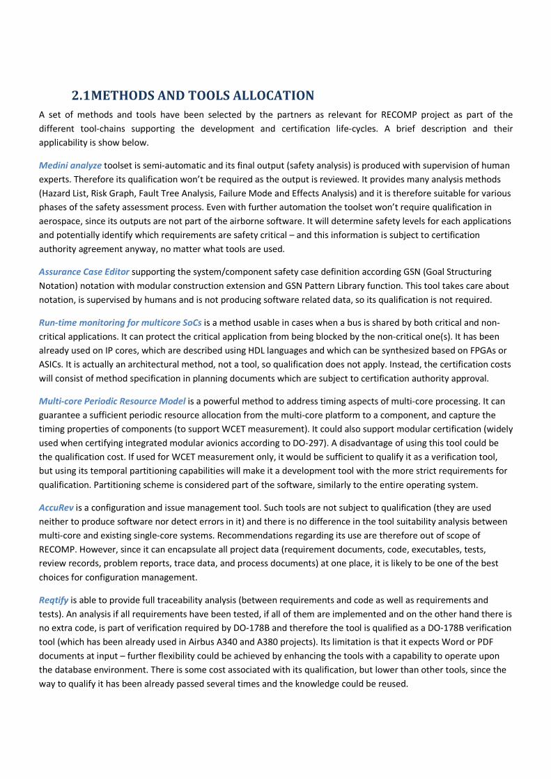
Medini analyze toolset is semi-automatic and its final output (safety analysis) is produced with supervision of human
experts. Therefore its qualification won’t be required as the output is reviewed. It provides many analysis methods
(Hazard List, Risk Graph, Fault Tree Analysis, Failure Mode and Effects Analysis) and it is therefore suitable for various
phases of the safety assessment process. Even with further automation the toolset won’t require qualification in
aerospace, since its outputs are not part of the airborne software. It will determine safety levels for each applications
and potentially identify which requirements are safety critical – and this information is subject to certification
authority agreement anyway, no matter what tools are used.
Assurance Case Editor supporting the system/component safety case definition according GSN (Goal Structuring
Notation) notation with modular construction extension and GSN Pattern Library function. This tool takes care about
notation, is supervised by humans and is not producing software related data, so its qualification is not required.
Run-time monitoring for multicore SoCs is a method usable in cases when a bus is shared by both critical and non-
critical applications. It can protect the critical application from being blocked by the non-critical one(s). It has been
already used on IP cores, which are described using HDL languages and which can be synthesized based on FPGAs or
ASICs. It is actually an architectural method, not a tool, so qualification does not apply. Instead, the certification costs
will consist of method specification in planning documents which are subject to certification authority approval.
Multi-core Periodic Resource Model is a powerful method to address timing aspects of multi-core processing. It can
guarantee a sufficient periodic resource allocation from the multi-core platform to a component, and capture the
timing properties of components (to support WCET measurement). It could also support modular certification (widely
used when certifying integrated modular avionics according to DO-297). A disadvantage of using this tool could be
the qualification cost. If used for WCET measurement only, it would be sufficient to qualify it as a verification tool,
but using its temporal partitioning capabilities will make it a development tool with the more strict requirements for
qualification. Partitioning scheme is considered part of the software, similarly to the entire operating system.
AccuRev is a configuration and issue management tool. Such tools are not subject to qualification (they are used
neither to produce software nor detect errors in it) and there is no difference in the tool suitability analysis between
multi-core and existing single-core systems. Recommendations regarding its use are therefore out of scope of
RECOMP. However, since it can encapsulate all project data (requirement documents, code, executables, tests,
review records, problem reports, trace data, and process documents) at one place, it is likely to be one of the best
choices for configuration management.
Reqtify is able to provide full traceability analysis (between requirements and code as well as requirements and
tests). An analysis if all requirements have been tested, if all of them are implemented and on the other hand there is
no extra code, is part of verification required by DO-178B and therefore the tool is qualified as a DO-178B verification
tool (which has been already used in Airbus A340 and A380 projects). Its limitation is that it expects Word or PDF
documents at input – further flexibility could be achieved by enhancing the tools with a capability to operate upon
the database environment. There is some cost associated with its qualification, but lower than other tools, since the
way to qualify it has been already passed several times and the knowledge could be reused.
[ARTEMIS JU RECOMP] [Deliverable 2.5 “Guidelines for developing certifiable systems and integration with existing tool flows”]
12
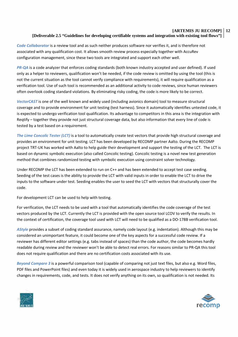
Code Collaborator is a review tool and as such neither produces software nor verifies it, and is therefore not
associated with any qualification cost. It allows smooth review process especially together with AccuRev
configuration management, since these two tools are integrated and support each other well.
PR-QA is a code analyzer that enforces coding standards (both known industry accepted and user defined). If used
only as a helper to reviewers, qualification won’t be needed, if the code review is omitted by using the tool (this is
not the current situation as the tool cannot verify compliance with requirements), it will require qualification as a
verification tool. Use of such tool is recommended as an additional activity to code reviews, since human reviewers
often overlook coding standard violations. By eliminating risky coding, the code is more likely to be correct.
VectorCAST is one of the well known and widely used (including avionics domain) tool to measure structural
coverage and to provide environment for unit testing (test harness). Since it automatically identifies untested code, it
is expected to undergo verification tool qualification. Its advantage to competitors in this area is the integration with
Reqtify – together they provide not just structural coverage data, but also information that every line of code is
tested by a test based on a requirement.
The Lime Concolic Tester (LCT) is a tool to automatically create test vectors that provide high structural coverage and
provides an environment for unit testing. LCT has been developed by RECOMP partner Aalto. During the RECOMP
project TRT-UK has worked with Aalto to help guide their development and support the testing of the LCT. The LCT is
based on dynamic symbolic execution (also called Concolic testing). Concolic testing is a novel new test generation
method that combines randomized testing with symbolic execution using constraint solver technology.
Under RECOMP the LCT has been extended to run on C++ and has been extended to accept test case seeding.
Seeding of the test cases is the ability to provide the LCT with valid inputs in order to enable the LCT to drive the
inputs to the software under test. Seeding enables the user to seed the LCT with vectors that structurally cover the
code.
For development LCT can be used to help with testing.
For verification, the LCT needs to be used with a tool that automatically identifies the code coverage of the test
vectors produced by the LCT. Currently the LCT is provided with the open source tool LCOV to verify the results. In
the context of certification, the coverage tool used with LCT will need to be qualified as a DO-178B verification tool.
AStyle provides a subset of coding standard assurance, namely code layout (e.g. indentation). Although this may be
considered an unimportant feature, it could become one of the key aspects for a successful code review. If a
reviewer has different editor settings (e.g. tabs instead of spaces) than the code author, the code becomes hardly
readable during review and the reviewer won’t be able to detect real errors. For reasons similar to PR-QA this tool
does not require qualification and there are no certification costs associated with its use.
Beyond Compare 3 is a powerful comparison tool (capable of comparing not just text files, but also e.g. Word files,
PDF files and PowerPoint files) and even today it is widely used in aerospace industry to help reviewers to identify
changes in requirements, code, and tests. It does not verify anything on its own, so qualification is not needed. Its

[ARTEMIS JU RECOMP] [Deliverable 2.5 “Guidelines for developing certifiable systems and integration with existing tool flows”]
13
power shows up on projects starting with already existing data, when the team is implementing change requests. It
dramatically improves effectiveness of various reviews.
MS Development Studio is a well-known competitive development environment. It helps the coder to produce
correct code by providing syntax checks, color differentiation, etc., and supports several compilers. It does not
require qualification, the code is still reviewed.
CODEO is a development environment recommended for use under PIKEOS operating system. Although its usage is
more limited than MS Development Studio, its advantage is that it supports running and debugging code in the target
environment. For the same reason as MS Development Studio it does not need to be qualified.
Interface Definition for Runtime monitoring category of tools and methods is a set supervising the influence of
applications on each other. Here, the certification costs grow with amount of features used. If used only to determine
the correct architecture and allocation of functions to individual cores, it won’t need to be qualified, but if using it to
provide temporal or spatial partitioning and to verify or validate the architecture the tool will become point of
certification authority attention. These tools and methods are definitely recommended, but the cost-benefit analysis
need to be performed from case to case.
Statistical model checking on constant slope timed I/O automata monitors simulations of the system, and then use
results from statistics to decide whether the system satisfies the property or not with some degree of confidence. By
nature, SMC is a compromise between testing and classical model checking techniques. It becomes an ideal choice
from both tool and process standpoint when probability requirements will be used in a project (refer to D4.2b for a
discussion on probabilistic approach to worst-case-response-time assurance). When used to verify probability
requirements as a tool, it will require verification tool qualification.
Stepwise design of real time systems with ECDAR is a method for refining abstract requirement descriptions to
concrete components and algorithms. ECDAR is a method and a tool for stepwise, compositional design of
component based, real time systems. If used as a process in the design when the components and algorithms will
undergo formal review, no qualification is required; if using the tool capability to output also verification results, the
qualification cost comes into project (this feature is enabled when integrated in a tool chain with Timed I/O
automata).
Schedulability analysis of mixed-critically real-time systems extends the state-of-the-art timing analysis of tasks sets
scheduled with Fixed Priority Scheduling (FPS) to consider the impact of partitions, but it can be easily extended to
other scheduling policies. This analysis targets partitioned architectures, where applications of different criticality
levels are separated using partitioning. Each application is running in its own partition. The analysis takes as input the
set of FPS task sets, the partition schedule tables on each PE, the allocation of tasks to PEs, and returns the worst-
case response time for each FPS task.
MCDO-“Mixed-critically design optimization” tool is suitable for Integrated Modular Avionics (IMA). The tool
optimizes of mapping of tasks to processors, the assignment of tasks to partitions, the sequence and size of the time
slots on each processor and the schedule tables for the applications, such that all applications are schedulable and
development cost minimized. The tool assumes all the tasks are scheduled using Static Cyclic Scheduling. It does not

[ARTEMIS JU RECOMP] [Deliverable 2.5 “Guidelines for developing certifiable systems and integration with existing tool flows”]
14
require qualification since it only helps to choose the correct partitioning scheme, it does not provide the partitioning
mechanism itself.
Event-B is a formal method for correct-by-construction development of systems through correctness preserving
refinement steps. Verification of Event-B models is performed by discharging proof obligations with tool support
from the Rodin platform. There is also the ProB tool offering model checking and animating facilities.
Within RECOMP project Event-B has been mainly used for the requirements modeling (SW Requirements) phase at
system level in the SW safety development lifecycle. Verification of Event-B models is performed by generating and
discharging proof obligations within the Rodin platform with the help of its associated theorem provers. Additional
support for this verification as well as for validation purposes is provided by the model checking and animating
(simulation) facilities of the ProB tool. The contribution of the Event-B method to the project objectives is stepwise
refinement-based approach for requirements modeling, analysis, verification and validation possibly leading to
discovery of design problems early on in a development process.
VerSÅA is expected to be used for contract-based verification of Simulink models. Simulink models are first
annotated by contracts describing functional properties and the tool checks that the model conforms to them.
Similarly to Event-B, it is considered a proof tool and therefore a formal method under DO-333 guidance. Here the
certification costs are more likely to be determined accurately, since the scope is known - the goal is to use this tool
as a replacement for unit tests. Therefore the qualification cost is expected to be similar to other automated
verification tools.
Bus Contention Analysis is a method to determine the extra delay incurred by the tasks due to contention on the
front side bus, assuming that the tasks are co-scheduled on different cores and access the shared main memory using
this shared bus. Since analyzing multi-cores to provide required timing guarantees is challenging, this method should
overcome the issues associated with traditional methods on measuring WCET. It determines an increase which is
then abstracted so that it can be integrated into the analyses of the worst-case execution time and worst-case
response time of the tasks, which are key properties in timing analyses and certification processes. It is not a tool and
therefore does not require any qualification. There may be some initial cost involved until the certification authorities
accept the method for the first time.
Pre-emption cost Analysis is a similar type of method to determine upper-bounds the cache-related pre-emption
delay that can be incurred by a given application, due to pre-emptions by other applications in the system. These
delays are then incorporated into timing margins as time-penalties to ensure that all timing requirements are
fulfilled. The exact level of safety integrity of proposed techniques depends on the exactness/completeness of the
information available about the hardware architecture on which the system is eventually deployed. It is therefore up
to the certification agencies to decide on a certain safety-level by providing more or less information about the
hardware architecture.
PharOS relies on a formal model of task, the timed constrained automata model. PharOS methodology ensures that
constraints expressed with high level description of the application constraints result in a deterministic system
providing strict temporal and spatial isolation. Since it produces a binary executable for a particular hardware target,

[ARTEMIS JU RECOMP] [Deliverable 2.5 “Guidelines for developing certifiable systems and integration with existing tool flows”]
15
and provides isolation (e.g. a layered software architecture prevents the current task to access anywhere else than its
initially allocated pages), it provides functionality similar to full operating system and needs therefore a rigorous
qualification.
Autofocus (AF3) is a powerful tool for modelling, developing, verifying and testing on a single surface, thus
simplifying the development workflow. It is able to decompose a system into logically distributed sub-systems,
namely components. The platform dependent models describe a hardware topology that is composed of hardware
components (e.g. cores of a multi-core system), which in turn may consist of hardware ports (sensors or actuators)
and busses. It has many various uses – as a code generator, schedule generator, or formal verification tool. The effort
associated with qualification will depend on the functions being used.
The following table shows the allocation of selected tools/methods to the Common Process Diagram cross-domain
stages according their capabilities.
Phase (Development/Safety Assessment) Regulation Activity
Med
ini (
ikv+
+)(T
EC)
Ass
uran
ce C
ase
Edit
or
(TEC
)
Ru
n-t
ime
mo
nit
ori
ng
for
mu
ltic
ore
SoC
s (U
GR
)
FTT
Mo
del
er
Mu
lti-
core
Per
iod
ic R
eso
urce
Mo
del
Acc
uR
ev
Req
tify
Co
de
Co
llab
ora
tor
PR
-QA
Vec
torC
AST
Lim
e C
on
colic
Tes
ter
ASt
yle
Bey
on
d C
om
par
e 3
MS
Dev
elo
pm
ent
Stu
dio
CO
DEO
Inte
rfac
e D
efin
itio
n f
or R
un
tim
e m
on
ito
ring
Stat
isti
cal m
od
el c
hec
king
on
co
nsta
nt s
lop
e ti
med
I/O
au
tom
ata
Step
wis
e d
esig
n o
f re
al t
ime
syst
ems
wit
h E
CD
AR
Sch
edu
lab
ility
an
alys
is o
f m
ixed
-cri
tica
lly r
eal-
tim
e sy
stem
s
MC
DO
-“M
ixed
-cri
tica
lly d
esig
n o
pti
miz
atio
n”
too
l
Even
t-B
Ver
SÅA
Bus
Co
nte
ntio
n A
nal
ysis
Pre
-em
pti
on
cos
t A
nal
ysis
Ph
arO
S
Au
tofo
cus
(AF3
)
D1. Concept Phase \ IEC-61508 01. Concept
S1. Hazard Analysis 02. Overall scope
03. Hazard & risk analysis
X
X
ISO-26262 3-05. Item Definition
X
3-06. Initialization of safety lifecycle
3-07. Hazard analysis and risk assessment
X
X
X

[ARTEMIS JU RECOMP] [Deliverable 2.5 “Guidelines for developing certifiable systems and integration with existing tool flows”]
16
Phase (Development/Safety Assessment) Regulation Activity
Med
ini (
ikv+
+)(T
EC)
Ass
uran
ce C
ase
Edit
or
(TEC
)
Ru
n-t
ime
mo
nit
ori
ng
for
mu
ltic
ore
So
Cs
(UG
R)
FTT
Mo
del
er
Mu
lti-
core
Per
iod
ic R
eso
urce
Mo
del
Acc
uR
ev
Req
tify
Co
de
Co
llab
ora
tor
PR
-QA
Vec
torC
AST
Lim
e C
on
colic
Tes
ter
ASt
yle
Bey
on
d C
om
par
e 3
MS
Dev
elo
pm
ent
Stu
dio
CO
DEO
Inte
rfac
e D
efin
itio
n f
or R
un
tim
e m
on
ito
ring
Stat
isti
cal m
od
el c
hec
king
on
co
nsta
nt s
lop
e ti
med
I/O
au
tom
ata
Step
wis
e d
esig
n o
f re
al t
ime
syst
ems
wit
h E
CD
AR
Sch
edu
lab
ility
an
alys
is o
f m
ixed
-cri
tica
lly r
eal-
tim
e sy
stem
s
MC
DO
-“M
ixed
-cri
tica
lly d
esig
n o
pti
miz
atio
n”
too
l
Even
t-B
Ver
SÅA
Bus
Co
nte
ntio
n A
nal
ysis
Pre
-em
pti
on
cos
t A
nal
ysis
Ph
arO
S
Au
tofo
cus
(AF3
)
3-08. Functional safety concept
X
ARP-4754
5.1.1. Functional Hazard Analysis (FHA) X
ARP-4754 5.1.4. Common Cause Analysis X
D2. System-level Requirements \ IEC-61508
04. Overall safety requirements X X X X X X
S2. Safety-related Architectural design
05. Overall safety requirements allocation X X
ISO-26262
4-05. Initiation of product development at system level
4-06. Specification of the technical safety requirements
X
X
ARP-4754
4.3. Allocation of Requirements to systems
X
X
D3. System Design (inc.
IEC-61508 10-03. E/E/PE System design &
X X X SI
LX X X X X X

[ARTEMIS JU RECOMP] [Deliverable 2.5 “Guidelines for developing certifiable systems and integration with existing tool flows”]
17
Phase (Development/Safety Assessment) Regulation Activity
Med
ini (
ikv+
+)(T
EC)
Ass
uran
ce C
ase
Edit
or
(TEC
)
Ru
n-t
ime
mo
nit
ori
ng
for
mu
ltic
ore
So
Cs
(UG
R)
FTT
Mo
del
er
Mu
lti-
core
Per
iod
ic R
eso
urce
Mo
del
Acc
uR
ev
Req
tify
Co
de
Co
llab
ora
tor
PR
-QA
Vec
torC
AST
Lim
e C
on
colic
Tes
ter
ASt
yle
Bey
on
d C
om
par
e 3
MS
Dev
elo
pm
ent
Stu
dio
CO
DEO
Inte
rfac
e D
efin
itio
n f
or R
un
tim
e m
on
ito
ring
Stat
isti
cal m
od
el c
hec
king
on
co
nsta
nt s
lop
e ti
med
I/O
au
tom
ata
Step
wis
e d
esig
n o
f re
al t
ime
syst
ems
wit
h E
CD
AR
Sch
edu
lab
ility
an
alys
is o
f m
ixed
-cri
tica
lly r
eal-
tim
e sy
stem
s
MC
DO
-“M
ixed
-cri
tica
lly d
esig
n o
pti
miz
atio
n”
too
l
Even
t-B
Ver
SÅA
Bus
Co
nte
ntio
n A
nal
ysis
Pre
-em
pti
on
cos
t A
nal
ysis
Ph
arO
S
Au
tofo
cus
(AF3
)
Verification) \ development 4
S3. Safety reqs. allocation ISO-26262
4-07. System Design X X
ASI
L4
ARP-4754
4.3. Allocation of System requirements to items X A
ARP-4754
4.4. Development of system architecture X
ARP-4754
5.1.2. Preliminary System Safety Assessment (PSSA)
X
X
ARP-4754 5.1.4. Common Cause Analysis
X
X
D4. Detailed HW Requirements IEC-61508
10.a1 E-E-PE system design requirements specification
S4. Detailed Safety Requirements ISO-26262
4-06. Specification of the technical safety requirements
X
X X

[ARTEMIS JU RECOMP] [Deliverable 2.5 “Guidelines for developing certifiable systems and integration with existing tool flows”]
18
Phase (Development/Safety Assessment) Regulation Activity
Med
ini (
ikv+
+)(T
EC)
Ass
uran
ce C
ase
Edit
or
(TEC
)
Ru
n-t
ime
mo
nit
ori
ng
for
mu
ltic
ore
So
Cs
(UG
R)
FTT
Mo
del
er
Mu
lti-
core
Per
iod
ic R
eso
urce
Mo
del
Acc
uR
ev
Req
tify
Co
de
Co
llab
ora
tor
PR
-QA
Vec
torC
AST
Lim
e C
on
colic
Tes
ter
ASt
yle
Bey
on
d C
om
par
e 3
MS
Dev
elo
pm
ent
Stu
dio
CO
DEO
Inte
rfac
e D
efin
itio
n f
or R
un
tim
e m
on
ito
ring
Stat
isti
cal m
od
el c
hec
king
on
co
nsta
nt s
lop
e ti
med
I/O
au
tom
ata
Step
wis
e d
esig
n o
f re
al t
ime
syst
ems
wit
h E
CD
AR
Sch
edu
lab
ility
an
alys
is o
f m
ixed
-cri
tica
lly r
eal-
tim
e sy
stem
s
MC
DO
-“M
ixed
-cri
tica
lly d
esig
n o
pti
miz
atio
n”
too
l
Even
t-B
Ver
SÅA
Bus
Co
nte
ntio
n A
nal
ysis
Pre
-em
pti
on
cos
t A
nal
ysis
Ph
arO
S
Au
tofo
cus
(AF3
)
ARP-4754
4.1.7. / 4.5. Item Requirement Specification
X
DO-254
HW Development life-cycle process
D5. Detailed SW Requirements IEC-61508
10 b1. Software safety requirements specification X
S4. Detailed Safety Requirements ISO-26262
4-06. Specification of the technical safety requirements
X
X
ARP-4754
4.1.7. / 4.5. Item Requirement Specification X
DO-178B SW Development life-cycle process X
D6. Detailed HW Design IEC-61508
10 a3. E-E-PE system design and development including ASICs and software
S5. Safety Functions Design ISO-26262
5-07. Hardware design X

[ARTEMIS JU RECOMP] [Deliverable 2.5 “Guidelines for developing certifiable systems and integration with existing tool flows”]
19
Phase (Development/Safety Assessment) Regulation Activity
Med
ini (
ikv+
+)(T
EC)
Ass
uran
ce C
ase
Edit
or
(TEC
)
Ru
n-t
ime
mo
nit
ori
ng
for
mu
ltic
ore
So
Cs
(UG
R)
FTT
Mo
del
er
Mu
lti-
core
Per
iod
ic R
eso
urce
Mo
del
Acc
uR
ev
Req
tify
Co
de
Co
llab
ora
tor
PR
-QA
Vec
torC
AST
Lim
e C
on
colic
Tes
ter
ASt
yle
Bey
on
d C
om
par
e 3
MS
Dev
elo
pm
ent
Stu
dio
CO
DEO
Inte
rfac
e D
efin
itio
n f
or R
un
tim
e m
on
ito
ring
Stat
isti
cal m
od
el c
hec
king
on
co
nsta
nt s
lop
e ti
med
I/O
au
tom
ata
Step
wis
e d
esig
n o
f re
al t
ime
syst
ems
wit
h E
CD
AR
Sch
edu
lab
ility
an
alys
is o
f m
ixed
-cri
tica
lly r
eal-
tim
e sy
stem
s
MC
DO
-“M
ixed
-cri
tica
lly d
esig
n o
pti
miz
atio
n”
too
l
Even
t-B
Ver
SÅA
Bus
Co
nte
ntio
n A
nal
ysis
Pre
-em
pti
on
cos
t A
nal
ysis
Ph
arO
S
Au
tofo
cus
(AF3
)
ARP-4754 4.6.2. & 4.6.3. Item Design
DO-254
HW Development life-cycle process X
D7. Detailed SW Design IEC-61508
10 b1. Software safety requirements specification
X
X
S5. Safety Functions Design
10 b2. Validation plan for software aspects of system safety X
10 b3. Software design and development
10 b4. PE Integration (hardware and software)
X
10 b5. Software operation and maintenance procedures
10 b6. Software aspects of system safety validation
X
DO-178B SW Development life-cycle process X

[ARTEMIS JU RECOMP] [Deliverable 2.5 “Guidelines for developing certifiable systems and integration with existing tool flows”]
20
Phase (Development/Safety Assessment) Regulation Activity
Med
ini (
ikv+
+)(T
EC)
Ass
uran
ce C
ase
Edit
or
(TEC
)
Ru
n-t
ime
mo
nit
ori
ng
for
mu
ltic
ore
So
Cs
(UG
R)
FTT
Mo
del
er
Mu
lti-
core
Per
iod
ic R
eso
urce
Mo
del
Acc
uR
ev
Req
tify
Co
de
Co
llab
ora
tor
PR
-QA
Vec
torC
AST
Lim
e C
on
colic
Tes
ter
ASt
yle
Bey
on
d C
om
par
e 3
MS
Dev
elo
pm
ent
Stu
dio
CO
DEO
Inte
rfac
e D
efin
itio
n f
or R
un
tim
e m
on
ito
ring
Stat
isti
cal m
od
el c
hec
king
on
co
nsta
nt s
lop
e ti
med
I/O
au
tom
ata
Step
wis
e d
esig
n o
f re
al t
ime
syst
ems
wit
h E
CD
AR
Sch
edu
lab
ility
an
alys
is o
f m
ixed
-cri
tica
lly r
eal-
tim
e sy
stem
s
MC
DO
-“M
ixed
-cri
tica
lly d
esig
n o
pti
miz
atio
n”
too
l
Even
t-B
Ver
SÅA
Bus
Co
nte
ntio
n A
nal
ysis
Pre
-em
pti
on
cos
t A
nal
ysis
Ph
arO
S
Au
tofo
cus
(AF3
)
D8. HW Development IEC-61508
10 a3. E-E-PE system design and development including ASICs and software X
S6. Safety Functions Implementation ISO-26262
5-06. Specification of hardware safety requirements X
5-07. Hardware design X
5-08. Evaluation of the hardware architectural metrics
5-10. Hardware integration and testing
ARP-4754 5.5. Item Verification X
ARP-4754
5.1.3. System Safety Assessment (SSA) X
ARP-4754 5.1.4. Common Cause Analysis X
DO-254
HW Development life-cycle process X

[ARTEMIS JU RECOMP] [Deliverable 2.5 “Guidelines for developing certifiable systems and integration with existing tool flows”]
21
Phase (Development/Safety Assessment) Regulation Activity
Med
ini (
ikv+
+)(T
EC)
Ass
uran
ce C
ase
Edit
or
(TEC
)
Ru
n-t
ime
mo
nit
ori
ng
for
mu
ltic
ore
So
Cs
(UG
R)
FTT
Mo
del
er
Mu
lti-
core
Per
iod
ic R
eso
urce
Mo
del
Acc
uR
ev
Req
tify
Co
de
Co
llab
ora
tor
PR
-QA
Vec
torC
AST
Lim
e C
on
colic
Tes
ter
ASt
yle
Bey
on
d C
om
par
e 3
MS
Dev
elo
pm
ent
Stu
dio
CO
DEO
Inte
rfac
e D
efin
itio
n f
or R
un
tim
e m
on
ito
ring
Stat
isti
cal m
od
el c
hec
king
on
co
nsta
nt s
lop
e ti
med
I/O
au
tom
ata
Step
wis
e d
esig
n o
f re
al t
ime
syst
ems
wit
h E
CD
AR
Sch
edu
lab
ility
an
alys
is o
f m
ixed
-cri
tica
lly r
eal-
tim
e sy
stem
s
MC
DO
-“M
ixed
-cri
tica
lly d
esig
n o
pti
miz
atio
n”
too
l
Even
t-B
Ver
SÅA
Bus
Co
nte
ntio
n A
nal
ysis
Pre
-em
pti
on
cos
t A
nal
ysis
Ph
arO
S
Au
tofo
cus
(AF3
)
D9. SW Development IEC-61508
10 a3. E-E-PE system design and development including ASICs and software
T2 X X
SI
L4 X
S6. Safety Functions Implementation
10 b3. Software design and development
ARP-4754 5.5. Item Verification
DO-178B SW Development life-cycle process X X X X X X
D10. System Integration IEC-61508
10 a4. E-E-PE system integration
S7. Functional Safety Testing
10 b4. PE integration (hardware and software)
X
ARP-4754 5.5. System Verification
X
D11. System Verification IEC-61508
07. Overall safety validation planning
S8. Safety Validation
13. Overall safety validation X
ARP-4754 5.5. System Verification X

[ARTEMIS JU RECOMP] [Deliverable 2.5 “Guidelines for developing certifiable systems and integration with existing tool flows”]
22
Phase (Development/Safety Assessment) Regulation Activity
Med
ini (
ikv+
+)(T
EC)
Ass
uran
ce C
ase
Edit
or
(TEC
)
Ru
n-t
ime
mo
nit
ori
ng
for
mu
ltic
ore
So
Cs
(UG
R)
FTT
Mo
del
er
Mu
lti-
core
Per
iod
ic R
eso
urce
Mo
del
Acc
uR
ev
Req
tify
Co
de
Co
llab
ora
tor
PR
-QA
Vec
torC
AST
Lim
e C
on
colic
Tes
ter
ASt
yle
Bey
on
d C
om
par
e 3
MS
Dev
elo
pm
ent
Stu
dio
CO
DEO
Inte
rfac
e D
efin
itio
n f
or R
un
tim
e m
on
ito
ring
Stat
isti
cal m
od
el c
hec
king
on
co
nsta
nt s
lop
e ti
med
I/O
au
tom
ata
Step
wis
e d
esig
n o
f re
al t
ime
syst
ems
wit
h E
CD
AR
Sch
edu
lab
ility
an
alys
is o
f m
ixed
-cri
tica
lly r
eal-
tim
e sy
stem
s
MC
DO
-“M
ixed
-cri
tica
lly d
esig
n o
pti
miz
atio
n”
too
l
Even
t-B
Ver
SÅA
Bus
Co
nte
ntio
n A
nal
ysis
Pre
-em
pti
on
cos
t A
nal
ysis
Ph
arO
S
Au
tofo
cus
(AF3
)
ARP-4754
5.1.3. System Safety Asssessment (SSA) X
ARP-4754 5.1.4. Common Cause Analysis
X
X
D12. Post-development Phases IEC-61508
14. Overall operation, maintenance and repair
15. Overall modification and retrofit
16. Decommissioning and disposal
ISO-26262 7. Production and operation
9-07 Analysis of dependent failures X
Supporting activities
Configuration Management X
Error and bug tracking X
Traceabilty management X
Source
X

[ARTEMIS JU RECOMP] [Deliverable 2.5 “Guidelines for developing certifiable systems and integration with existing tool flows”]
23
Phase (Development/Safety Assessment) Regulation Activity
Med
ini (
ikv+
+)(T
EC)
Ass
uran
ce C
ase
Edit
or
(TEC
)
Ru
n-t
ime
mo
nit
ori
ng
for
mu
ltic
ore
So
Cs
(UG
R)
FTT
Mo
del
er
Mu
lti-
core
Per
iod
ic R
eso
urce
Mo
del
Acc
uR
ev
Req
tify
Co
de
Co
llab
ora
tor
PR
-QA
Vec
torC
AST
Lim
e C
on
colic
Tes
ter
ASt
yle
Bey
on
d C
om
par
e 3
MS
Dev
elo
pm
ent
Stu
dio
CO
DEO
Inte
rfac
e D
efin
itio
n f
or R
un
tim
e m
on
ito
ring
Stat
isti
cal m
od
el c
hec
king
on
co
nsta
nt s
lop
e ti
med
I/O
au
tom
ata
Step
wis
e d
esig
n o
f re
al t
ime
syst
ems
wit
h E
CD
AR
Sch
edu
lab
ility
an
alys
is o
f m
ixed
-cri
tica
lly r
eal-
tim
e sy
stem
s
MC
DO
-“M
ixed
-cri
tica
lly d
esig
n o
pti
miz
atio
n”
too
l
Even
t-B
Ver
SÅA
Bus
Co
nte
ntio
n A
nal
ysis
Pre
-em
pti
on
cos
t A
nal
ysis
Ph
arO
S
Au
tofo
cus
(AF3
)
Difference
3 METHOD/TOOL ALLOCATION (COMPONENT)
Today, components have to be certified as part of a system, and cannot be certified separately. Assume-guarantee methods have been used to support compositional verification. However, these methods are not applicable to certification. Certification can use compositional verification only if separation mechanisms (called “robust partitioning” in avionics, and “separation” in security) are provided by WP3. This is done offline, using testing and/or verification to determine the correctness of the implementation and online using runtime monitoring to check the separation between the safety and non safety-critical parts. The following table shows the allocation of proposed RECOMP tools for component validation.
Scope Techniques/Component Samples Tools (functionality, scope, references)
Virtualization ISA Translation (T)
Paravirtualization (T)
Hardware Virtualization (T)
Partial Emulation (T)
Resource Allocation (T)
Hypervisor (C) SecVisor, BitVisor,
XEN, VmKit, MCDO

[ARTEMIS JU RECOMP] [Deliverable 2.5 “Guidelines for developing certifiable systems and integration with existing tool flows”]
24
SpuMone
Microkernel (C)
Hardware Support for Spatial and
Temporal Separation (T)
Timing Analyzable Processor
Architecture (T)
MCDO, Schedulability analysis of mixed-
critically real-time systems, FFT-Model
Memory subsystem (T)
Bus Contention Analysis,
Pre-emption cost Analysis (restricted to
monocores)
Communication facilities (T)
Commercial Solutions (C )
ARM Trustzone,
Intel-VT, AMD-V
VSD Model (C)
IDA Many-core Model (C )
Monitoring
Monitoring (SW or HW
implementation) (C )
Functionalities: Power/Behaviour
Alamo, Annotation
PreProcessor
(APP), Temporal
Rover/DB-Rover,
MaC/MaCware,
Java with
assertions (JASS),
Copilot,
DynaMICs, Lime
Concolic Tester,
ESTEREL, LOLA,
Larva
Run-time monitoring for multicore SoCs
(UGR). Scope: On-chip peripherals of a SoC.
Functionality: Access blocking on a shared-
bus to non-critical master peripherals
when they suffer from any deviation from
its intended behaviour. Additional details
at deliverable 3.1 of WP3. IDAMC-
Interface definition for Run-time
Monitoring (IDAMC Platform).
Operating Autosar OS (C ) EB tresos Studio (Configuration)

[ARTEMIS JU RECOMP] [Deliverable 2.5 “Guidelines for developing certifiable systems and integration with existing tool flows”]
25
Systems
PharOS (C )
ψC toolchain, PharOS generation tool
(configuration)
OpenRTOS(C ) Xilinx EDK
HARTEX(C ) COMDES Tool-chain (WP3)
PIKEOS (C ) Codeo
DEOS- Digital Engine OS(C )
OSEK(C )
ARINC 653 (C )
MCDO, Schedulability analysis of mixed-
critically real-time systems
RTEMS(C )
ECOS(C )
Hardware Memory system (T)
Cache, Physcial,
Virtual…
Interrupt architecture (T)
Board (C ) Event-B (Intel X86, TMS570, AX32, ACP)
Communications (board)(C )
CAN, LIN, FlexRay.
PROFIBUS,
PROFISAFE,
ETHERNET
Communications (Core-core)
(Communication channel,
memory usage model) (T)
MCAPI, OpenMP,
MPI Multi-core Periodic Resource Model
System Device level, Control system Event-B, Simulink, VerSAA

[ARTEMIS JU RECOMP] [Deliverable 2.5 “Guidelines for developing certifiable systems and integration with existing tool flows”]
26
4 TOOL CHAIN PER APPLICATION DOMAIN
This chapter provides as example a description of some tool chains identified for the different domains under
analysis at RECOMP.
List of
tools/methods
Responsible Domain Application Use Comments
GEMDE
certification
TEC Common Sense & Avoid
(UAV)
Support for certification
tasks
Developed at
Recomp
Tool Chain
Analyzer (TCA)
Validas Common Support tool qualification
tasks
Developed at
Recomp
Tactic-Based
Testing
Validas Common Developed at
Recomp
Medini
(ikv++)(TEC)
TEC Avionics Sense & Avoid
(UAV)
Support safety analysis Tool develop by
third party and
tested at
RECOMP
Assurance Case
Editor (TEC)
TEC Avionics Sense & Avoid
(UAV)
Safety Case development Developed at
Recomp
Run-time
monitoring for
multicore SoCs
(UGR)
UGR Avionics Sense & Avoid
(UAV)
SoC designs based on
reconfigurable devices.
Solutions requiring co-
design decisions and using
third-party IP cores
without qualification.
Developed at
Recomp
AccuRev Thales Avionics Avionics Signal
Generator
For configuration
management, issue
tracking and process
enforcement
Tool develop by
third party and
tested at
RECOMP
Reqtify Thales Avionics Avionics Signal
Generator
traceability analysis Tool develop by
third party and
tested at
RECOMP
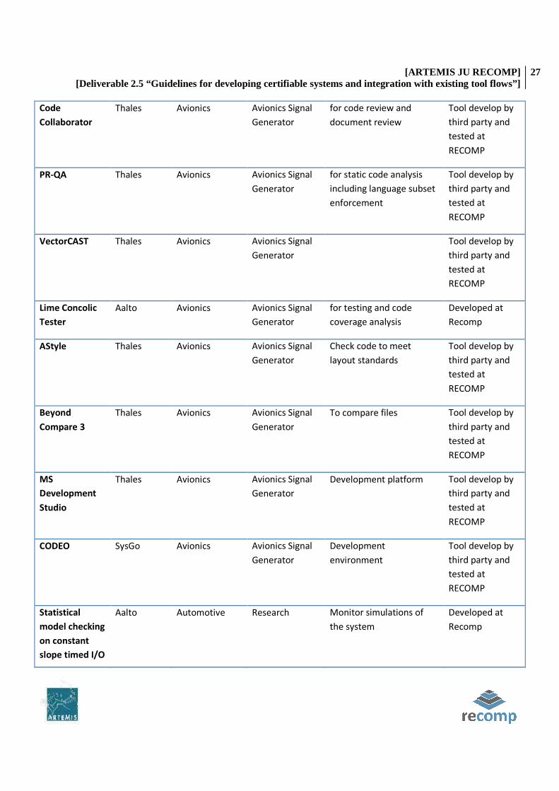
[ARTEMIS JU RECOMP] [Deliverable 2.5 “Guidelines for developing certifiable systems and integration with existing tool flows”]
27
Code
Collaborator
Thales Avionics Avionics Signal
Generator
for code review and
document review
Tool develop by
third party and
tested at
RECOMP
PR-QA Thales Avionics Avionics Signal
Generator
for static code analysis
including language subset
enforcement
Tool develop by
third party and
tested at
RECOMP
VectorCAST Thales Avionics Avionics Signal
Generator
Tool develop by
third party and
tested at
RECOMP
Lime Concolic
Tester
Aalto Avionics Avionics Signal
Generator
for testing and code
coverage analysis
Developed at
Recomp
AStyle Thales Avionics Avionics Signal
Generator
Check code to meet
layout standards
Tool develop by
third party and
tested at
RECOMP
Beyond
Compare 3
Thales Avionics Avionics Signal
Generator
To compare files Tool develop by
third party and
tested at
RECOMP
MS
Development
Studio
Thales Avionics Avionics Signal
Generator
Development platform Tool develop by
third party and
tested at
RECOMP
CODEO SysGo Avionics Avionics Signal
Generator
Development
environment
Tool develop by
third party and
tested at
RECOMP
Statistical
model checking
on constant
slope timed I/O
Aalto Automotive Research Monitor simulations of
the system
Developed at
Recomp
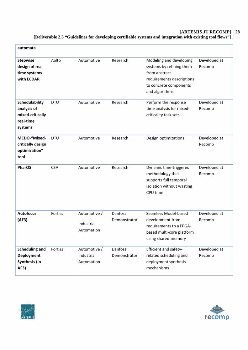
[ARTEMIS JU RECOMP] [Deliverable 2.5 “Guidelines for developing certifiable systems and integration with existing tool flows”]
28
automata
Stepwise
design of real
time systems
with ECDAR
Aalto Automotive Research Modeling and developing
systems by refining them
from abstract
requirements descriptions
to concrete components
and algorithms.
Developed at
Recomp
Schedulability
analysis of
mixed-critically
real-time
systems
DTU Automotive Research Perform the response
time analysis for mixed-
criticality task sets
Developed at
Recomp
MCDO-“Mixed-
critically design
optimization”
tool
DTU Automotive Research Design optimizations Developed at
Recomp
PharOS CEA Automotive Research Dynamic time-triggered
methodology that
supports full temporal
isolation without wasting
CPU time
Developed at
Recomp
Autofocus
(AF3)
Fortiss Automotive /
Industrial
Automation
Danfoss
Demonstrator
Seamless Model-based
development from
requirements to a FPGA-
based multi-core platform
using shared-memory
Developed at
Recomp
Scheduling and
Deployment
Synthesis (in
AF3)
Fortiss Automotive /
Industrial
Automation
Danfoss
Demonstrator
Efficient and safety-
related scheduling and
deployment synthesis
mechanisms
Developed at
Recomp

[ARTEMIS JU RECOMP] [Deliverable 2.5 “Guidelines for developing certifiable systems and integration with existing tool flows”]
29
MC-Platform
Code
Generation (in
AF3)
Fortiss Automotive /
Industrial
Automation
Danfoss
Demonstrator
Application Code
generation based on
deployment and
generated communication
infrastructure based on
schedule. Including I/O
accesses
Developed at
Recomp
Multi-mode
scheduling
analysis
ISEP Automotive Research Support timing analysis Developed at
Recomp
Preemption
cost analysis
ISEP Automotive Research Method to determine
upper-bounds the cache-
related pre-emption delay
that can be incurred by a
given application, due to
pre-emptions by other
applications in the system
Developed at
Recomp
Bus/NoC
contention
analysis
ISEP Automotive Research Method to determine the
extra delay incurred by
the tasks due to
contention on the front
side bus
Developed at
Recomp
Event-B AAU Industrial
Automation
Danfoss case
study
Requirements modelling
and verification
Developed by
the Event-B
community in
general and
tested at
Recomp
Simulink AAU Common Extensive use in
the industry
Tool develop by
third party and
tested at
RECOMP
VerSÅA AAU Automotive /
Industrial
Automation
Research Contract-based verifier for
Simulink
Developed partly
at Recomp

[ARTEMIS JU RECOMP] [Deliverable 2.5 “Guidelines for developing certifiable systems and integration with existing tool flows”]
30
5 TOOL CHAIN QUALIFICATION
The goal of the tool chain qualification is not to qualify all used tools, but to show how the qualification costs can be
reduced when the tools are used in a well-defined tool chain and to identify the (reduced) qualification needs for the
tools in different demonstrators. The tool chain qualification method has been developed from Validas AG within
work package 4 of RECOMP. This section describes a short overview and the application of the method to the
demonstrators such that the demonstrators could make their contributions.
5.1 DESCRIPTION OF THE TOOL CHAIN QUALIFICATION METHOD
The tool chain analysis method has been developed and applied within the RECOMP project. It automatically
computes the tool confidence level (TCL) according to ISO 26262 and can also reduce the required qualification rigor
and data according to DO-330. The method bases on a formal model of tools, use cases, artifacts, errors checks and
restrictions etc. and a calculus to compute the TCL. Furthermore it has an error model to systematically derive
potential errors using attributes that characterize the tools (black-box and white-box). An important aspect of the
method is that it allows formalizing assumptions in order to express that certain checks for potential errors during
the development process have to be applied from the developers. The TCL can be computed including and without
the assumptions.
The tool chain analysis method has been implemented from Validas AG in the “Tool Chain Analyzer” that is freely
available prototype at http://www.validas.de/TCA152.zip. It also contains a report generation feature and a long
documentation explaining the model and features. The Tool Chain Analyzer has TCL 1 with the assumption that the
confirmation review of the TCLs and the qualification measures is executed on the generated report. Since this
review is required from ISO 26262 the tool is uncritical and required no further qualification.
The tool has been applied from Validas in two big industrial projects. One result was a tool chain with 39 tools, which
could be extended by small process extensions and redundancy, such that only the qualification of one tool was
necessary. Compared with the results of a fixed tool confidence level classification as proposed in literature it has
dramatically reduced the tool qualification costs by reducing the number of tools to be qualified from 13 to 1.
Therefore the tool chain analysis method has been selected to integrate and describe the methods developed within
RECOMP project.
5.2 REQUIRED INFORMATION FOR EACH USED TOOL
For every tool in the demonstrator the following information is used on the use of the tool WITHIN the
demonstrator. It is not desired to provide a tool description of common tools like Make, gcc … but to show how ALL
tools are used within the demonstrators.
The following information shall be collected for the tools:
• Name of the tool • Used features of the tool (including their capacity to detect errors of humans and tools)

[ARTEMIS JU RECOMP] [Deliverable 2.5 “Guidelines for developing certifiable systems and integration with existing tool flows”]
31
• Use cases of the tool with input and output artifacts e.g. • SILTest-Compile: SourceCode, Libraries-> SIL-Executable, Logfile • SILTest-Execution: SIL-Executable, Stimuli, SIL-References -> SIL-Values, SIL-Result, Logfile
Note that this does not only refer to the RECOMP tools but to all used tools in the demonstrators. The tools can also
be directly formalized using the tool chain analyzer. In this case the detailed description of use cases is not required
in this document but contained in the formal tca-file.
5.3 SUPPORTING TOOL CHAINS
Name: Tool Chain Analyzer (TCA)
Description: The TCA is used to determine the Tool Confidence Level (TCA) according to ISO 26262 automatically based on a formal model of use-cases, tool-features, errors, artifacts, checks and restrictions. With the computed TCL and the ASIL the required qualification need for the tools within safety critical projects can be determined. Tool certification is an option which is not required from ISO 26262. The method can be applied to single tools and to integrated tool chains. A tool prototype has been developed from Validas AG as an Eclipse tool and can be evaluated during the RECOMP project (see WP4 documentation). Please contact Oscar Slotosch for more information.
ASIL: D
Inputs: Tool Descriptions with name, use cases, potential errors, checks/restrictions, artifacts
Outputs: XML-formalization of the modeled inputs, TCL of the tools, reviewable documentation
Use-cases: both use-cases rely on the feature TCL determination:
determination of TCL for single tools with one or more use-cases, e.g. a target compiler
determination of TCL for integrated tools chains, e.g. a model-based development tool chains with code-generator, rule checker, compiler, test tool, version control and tracing tool
Potential errors :
TCL-feature (both us cases): wrong TCL (lower than required). In this case the TCA would say the analyzed tool is uncritical, while it is critical and can introduce errors into the products
Persistency feature (both use-cases) wrong XML representation: the modeled information is not stored correctly in the XML file
Checks to detect the errors:
Wrong TCL: this error is checked during the required confirmation review of the results with HIGH probability
wrong persistency: if information is not stored the TCA will detect this when the model is opened and the TCL is recomputed with HIGH probability
Therefore the TCL of the TCA tool is TCL 1 under the assumption that it is used together with the review required by ISO.
Name: Standard Formalizer
Description: Standard Formalizer serves as a formalization of standards and system models. It generates verification conditions (VCs) for all modeled requirements and all components of the system. The prototype has been developed within RECOMP WP4 to ease the process of certification and to precisely show where the developed methods of RECOMP help to reduce certification effort. It bases on a common meta model for ISO 26262 (including a system model) and IEC 61508. The prototype has been developed from Validas AG and is available at https://research.it.abo.fi/confluence/display/RECOMP/UML+tool+for+task+9+of+task+4.2a

[ARTEMIS JU RECOMP] [Deliverable 2.5 “Guidelines for developing certifiable systems and integration with existing tool flows”]
32
ASIL: D
Inputs: Formalized Standards (meta model conforming XML), ISO 26262 like system structure description (meta model conforming XML)
Outputs: verification conditions (meta model conforming XML), including the number of generated VCs
Use-cases:
formalization of standards to precisely determine the semantics of the textual and graphical descriptions
generation of verification conditions
Potential errors:
standards are incompletely formalized (parts are omitted, or the tool discards them)
wrong verification conditions generated
verification conditions not completely generated
Checks to detect the errors
Incomplete standard: should be reviewed after the formalization. Important: count the requirements in the standard. This detects missing elements with a HIGH probability
Wrong VCs: this will be detected during the verification of the generated conditions with HIGH probability
Incomplete VCs: this will be detected since the number of the generated VCs can be easily checked against the number of requirements, multiplied with the number of system elements, e.g. a standard with 1000 requirements, applied to a system of 8 parts should generate 8000 VCs.
Therefore the TCL of the Standard Formalizer tool is TCL 1, if the suggested reviews are performed
Name: GEMDE Certification
Description: Executable certification framework that helps the development of above mentioned systems of system according to relevant safety standards and companies’ internal regulations.
ASIL: D
Inputs: Formalized Standards/Projects (meta model conforming XML) or manually inserted.
Outputs: verification conditions/Reference regulation (meta model conforming XML
Use-cases:
Three types of roles provide three possible views of the final tool, some functionalities will be exclusively of one view and others may be shared by more than one role. The following table provides a superficial vision of the views, their main functionalities and the correspondent actors.
View Actors Functionalities
Quality view Quality Manager
Selection and definition of the Qualification Reference
Definition of the scope of the Qualification Reference
Technical view
Technical Manager/
Project Leader
Developer
Definition of the Qualification Project and associated Qualification Reference
Definition of the scope of the Qualification Project
Definition of evidences
Reporting of the status of the Qualification Project (attending the evidences)
Assessment view Quality Manager
Assessment or validation of the Qualification Project against the
Qualification Reference

[ARTEMIS JU RECOMP] [Deliverable 2.5 “Guidelines for developing certifiable systems and integration with existing tool flows”]
33
Potential errors:
Incomplete certification requirements for instantiated project.
Checks to detect the errors:
The Quality Manager, after opening the Qualification Project should check each reference requirement and their evidences. Then, he should apply the correspondent status to the requirement, comments and whatever he considers necessary to establish if the requirement has been fulfilled. The user can ask to the Certification Framework the status of the project regarding to the evidences’ status in order to see a global report of the fulfillment of the Qualification Reference.
5.4 SUITABLE TOOLS PER DEMONSTRATORS
5.4.1 AVIONICS DOMAIN
On the next table we have included the selected tools developed or tested during the different demonstrator and
application developments. The responsible column describes which partner has been responsible weather for the
development of the tool or the testing of a third party tool on the context of the demonstrator.
Tool Name Use Application Responsible
Medini (ikv++)(TEC) Support safety analysis Sense & Avoid (UAV) TEC
Assurance Case Editor
(TEC)
Safety Case development Sense & Avoid (UAV) TEC
Run-time monitoring
for multicore SoCs
(UGR)
SoC designs based on reconfigurable
devices. Solutions requiring co-design
decisions and using third-party IP cores
without qualification.
Sense & Avoid (UAV) UGR
AccuRev For configuration management, issue
tracking and process enforcement
Avionics Signal Generator Thales
Reqtify traceability analysis Avionics Signal Generator Thales
Code Collaborator for code review and document review Avionics Signal Generator Thales
PR-QA for static code analysis including
language subset enforcement
Avionics Signal Generator Thales
VectorCAST for testing and code coverage analysis Avionics Signal Generator Thales
Lime Concolic Tester for coverage analysis Avionics Signal Generator Aalto

[ARTEMIS JU RECOMP] [Deliverable 2.5 “Guidelines for developing certifiable systems and integration with existing tool flows”]
34
AStyle Check code to meet layout standards Avionics Signal Generator Thales
Beyond Compare 3 To compare files Avionics Signal Generator Thales
MS Development
Studio
Development platform Avionics Signal Generator Thales
CODEO Development environment Avionics Signal Generator SysGo
Interface Definition for
Runtime monitoring
Support safety analysis Research TUBS
5.4.1.1 TOOLS USES
This section describes the tools and methods used to develop this demonstrator before and during RECOMP. The
pilot project before RECOMP sought to make use of the latest tools available. This was to ascertain a good tool
solution for this type of development which could be recommended for inclusion in the Thales design process.
The key tools used prior to RECOMP were:
• AccuRev – for configuration management, issue tracking and process enforcement • Reqtify – for traceability analysis • Code Collaborator – for code review and document review • PR-QA – for static code analysis including language subset enforcement.
The key tools used during RECOMP are
• VectorCAST – for testing and code coverage analysis • Lime Concolic Tester
5.4.1.1.1 ACCUREV
Used features
AccuRev is a configuration and issue management tool.
• Configuration management • Issue management. • The powerful streaming architecture which can naturally match the development workflow and also allow
processes to be enforced. • The ‘time-safe’ architecture which means that past activity cannot be altered.
Input/Output
Input: Project documentation.
Output: As defined in the previous section.

[ARTEMIS JU RECOMP] [Deliverable 2.5 “Guidelines for developing certifiable systems and integration with existing tool flows”]
35
Capacity to detect errors
In concert with other tools, AccuRev enables other tools to detect errors. This capability is documented as part of the
other tools descriptions of how they can detect errors.
AccuRev prevents errors through process enforcement. This stops the user from being able to make errors.
AccuRev maintains all project information including:
• Documents • Code • Executables • Verification • Code reviews • Traceability • Processes.
This enables errors to be detected by users through identification of changes in each process step.
Use Cases
AccuRev has been used for configuration management, issue tracking and process enforcement for documents and
software.
The way AccuRev has been used for documents is identified in
Figure 3. This shows the process that a document must pass through in order to be issued. This is enforced through
AccuRev, other tools described later and by a number of stake holders.
The way AccuRev has been used for software is defined in Figure 4. This shows the process that all software must
pass through in order to be released. This is enforced through AccuRev, other tools described later and by a number
of stake holders.

[ARTEMIS JU RECOMP] [Deliverable 2.5 “Guidelines for developing certifiable systems and integration with existing tool flows”]
36
Figure 3: AccuRev Document Use Case/Process

[ARTEMIS JU RECOMP] [Deliverable 2.5 “Guidelines for developing certifiable systems and integration with existing tool flows”]
37
release_integrationrelease_verificationrelease_QArelease
Dynamic stream created for this
issue, off
integration stream
Developer creates
workspace (or moves one) off this
dynamic stream
Developer carries out code
development in
workspace
START
Issue is created for code
User 1 Workspace
User 2 Workspace
END
release_issue_
Developer performs own
informal tests
Developer
promotes by issue* to issue
stream
Developer promotes by file*
to integration
stream
Review exists for
this issue?
Create Code Collaborator
review for this issue
Add transaction
relating to the promote into the
integration stream
Reviewers review differences
between latest and previous transaction non-interactively
online. Reviewers also consider
results of builds and tests. Reviewers also consider results of static analysis. Comments may be
added and defect reports may be marked fixed.Are all
reviewers done?
Developer goes through review comments,
responding to some or all with own comments.
Code Collaborator interactive online meeting is held, reaching agreement and raising any defect reports, which
are marked as “internally tracked”.
Do any defect reports remain?
Yes
Yes
No
No
Reviewers finish review
AccuRev issue is closed
Move issue
stream off pass-through for
completed issues
Completed-issue pass-through
stream exists?
Create pass-through
stream for completed issues, off integration
stream
Lock the issue
stream
Promote issue by
file* from integration stream
to verification stream
Snapshot pass-through
stream exists?
Create pass-through stream for
snapshots, off verification stream
Create release candidate
snapshot off this
pass-through
Create dynamic stream off this
snapshot
Create (or move) workspace off this dynamic stream
Rename Software folder to Snapshot/0.0. /
Software, where is the
release candidate number
Tester runs formal tests on the
release candidate in workspace
Tester promotes
results into dynamic stream
using the subissue
Create new
subissue
Create snapshot off dynamic
stream Yes
No
No
Yes
No
Yes
Agreement reached on all
areas?
YesModerator helps to resolve remaining
areas.
No
Tester runs informal nightly
and ad hoc builds
and tests on integration stream
Tester or
reviewers run static analysis on integration stream
Lock the
verification stream to prevent further promotes into it
* Note that there are different ways to promote from one stream to another. It is possible to promote by file, by transaction or by issue. This project has tried to use
the seemingly most suitable approach, depending on the situation. It should be noted that there may be a better solution and also that the latest version of AccuRev (version 4.9) has some changes to mitigate a promote-by-issue problem.
Tester promotes* to QA stream
QA checks that version of code relating to final
transaction of review matches
release candidate
snapshot
Formal tests
OK?No
Yes
Is QA
satisfied?Yes
No
QA promotes* to
release stream
Snapshot pass-through
stream exists?
Create pass-through stream for
snapshots, off release stream
Create release snapshot off this
pass-through
No
QA runs a file comparison
between the release candidate
snapshot and the release snapshot
Is QA satisfied?
Unlock the verification stream
to allow further promotes into it
Note that for this project, all the
issues were completed and promoted to the integration stream first. Then, the integration stream was locked.
Then, promoted from integration to verification stream by file, en masse.
Initial Work
Capture of Release
QA Part 2
Yes
Remove release
snapshot No
Yes
Post-Review Actions
QA checks that all relevant standards
and procedures have been
followed for this
issue
Is QA
satisfied?
No
Yes
QA Part 1
Formal Testing
Capture of Release Candidate
Review Process
Remove release
candidate snapshot
Figure 4: AccuRev Software UseCase/Process

[ARTEMIS JU RECOMP] [Deliverable 2.5 “Guidelines for developing certifiable systems and integration with existing tool flows”]
38
5.4.1.1.2 REQTIFY
Used features
Reqtify is a traceability analysis tool. It is used to support requirements traceability where requirements are specified
in documents such as Word or PDF documents. Reqtify is qualified as a DO-178B verification tool, and has been used
in Airbus A340 and A380 projects, for example.
It is used to support traceability from the requirements into the implemented source code and to support traceability
into the formal tests.
Input/Output
Input: Project Requirements
Output:
• Coverage analysis, traceability • Management of requirements changes, creations, deletions, • Upstream and downstream impact analysis, help for regression risk management
Capacity to detect errors
Reqtify detects errors in requirements coverage. This can be seen in Figure 5. Reqtify ensures that:
• Software and hardware requirements combined cover all system requirements, • The design document and test plan 100% cover the system requirements, • All requirements are covered by code and there is no dead code.

[ARTEMIS JU RECOMP] [Deliverable 2.5 “Guidelines for developing certifiable systems and integration with existing tool flows”]
39
Figure 5: Reqtify error detection
Use Cases
Reqtify is used to ensure that the documents identified in Figure 5 have 100% coverage. This is achieved by using
Reqtify to check that a document has 100% coverage, before the document is released for formal review in the
process defined in
Figure 3.
Reqtify is used to ensure that the code identified in Figure 5 must have 100% coverage. This is achieved by using
Reqtify to check that a source code has 100% coverage, before the source code is released for formal testing in the
process defined in Figure 4.
5.4.1.1.3 CODE COLLABORATOR
Used features
Code Collaborator is a tool that is used to support code reviews and documents reviews. It integrates with AccuRev,
thus supporting traceability of review material since specific transactions can be loaded for review. Code Collaborator
allows real-time or non real-time discussion of issues raised during reviews. It also provides a record of review
comments. Defects can be generated and tracked by the tool or by an external issue tracker.

[ARTEMIS JU RECOMP] [Deliverable 2.5 “Guidelines for developing certifiable systems and integration with existing tool flows”]
40
A particularly helpful feature with code reviews is that changes to files are readily identified when a new
configuration management transaction is loaded into a review. This means that the review can focus on changes to
files and fixes to defects can also be easily verified.
Input/Output
Input: Source Code
Output: Defect Tracking & Management results
Capacity to detect errors
Code Collaborator does not detect errors itself; rather supports reviewers in their reviews, ensuring that document
and code reviews are complete.
Use Cases
Code Collaborator’s use with respect to documents is identified in the Formal Review block in
Figure 3. Code Collaborator’s use with respect to code is identified in the Review process block in Figure 4.
5.4.1.1.4 VECTORCAST
Used features
VectorCAST/C++ primarily addresses unit testing of C/C++, with the provision of coverage information. It builds up a
test harness and allows the user to specify test vectors. It then runs the test harnesses and measures coverage.
Input/Output
Input: C/C++ Source Code
Output: Defects as defined bellow.
Capacity to detect errors
VectorCAST detects errors by checks that
• Formal testing performs an appropriate level of MC/DC testing on all conditions in the code • That there is no dead code that is not covered by test cases.
In combination with Reqtify, VectorCAST closes the loop to ensure that every line of code is covered by a
requirement and every line of code is tested by a test based on a requirement.
Use Cases
VectorCAST’s UseCase for code is identified in the Formal testing block in Figure 4.

[ARTEMIS JU RECOMP] [Deliverable 2.5 “Guidelines for developing certifiable systems and integration with existing tool flows”]
41
5.4.1.1.5 PR-QA C++
Used features
PR-QA C++ is a software analysis tool for C++ that enforces industry coding standards such as the MISRA C++ Coding
Standard, as well as local coding standards. It carries out static analysis on code and also measures various metrics
such as cyclomatic complexity.
Input/Output
Input: C/C++ Source Code
Output: Defects and non-conformity versus MISRA Coding standard.
Capacity to detect errors
PR-QA indirectly detects errors, in that it detects code written in a way that is more likely to contain errors. By
eliminating risky coding, the code is more likely to be correct.
Use Cases
PR-QA’s UseCase for code is identified in the Initial Work block in Figure 4. All code should pass the PR-QA tests
before it is checked into source control.
PR-QA’s UseCase is also identified in the Review Process block in Figure 4. It should be verified that all code that is
being reviewed passes the PR-QA tests.
5.4.1.1.6 ASTYLE
Used features
AStyle is a simple tool that allows C and C++ to be ‘beautified’. Although developers would aim to meet layout
standards whilst coding, it allowed an automated check and update to be carried out as well.
Input/Output
Input: C/C++ Source Code
Output: Defects and non-conformity versus predefined programming style.
Capacity to detect errors
AStyle ensures that the code is laid out in a consistent way. This makes code easier to understand, modify and review
accurately.
[ARTEMIS JU RECOMP] [Deliverable 2.5 “Guidelines for developing certifiable systems and integration with existing tool flows”]
42
Use Cases
AStyle’s Use Case for code is identified in the Initial Work block in Figure 4. AStyle should be run on all code before it
is checked into source control.
5.4.1.1.7 BEYOND COMPARE 3
Used features
Beyond Compare 3 is a powerful file differences and merge tool. Aside from supporting the comparison of text files,
it also allows the comparison of the text content of a number of binary file formats such as Word files, PDF files and
PowerPoint files.
Input/Output
Input: Any document
Output: Document differences
Capacity to detect errors
Beyond Compare protects the user from making an error, when the user merges a change request into the
integration stream; also supports the user in identifying changes that have been made to files, enabling the user to
identify errors during the review process.
Use Cases
Beyond Compare’s Use Case for code is identified in the Initial Work block in Figure 4. Beyond Compare’s should be
used when necessary, to merge a change request into the integration stream, before the change is promoted into the
integration stream.
5.4.1.1.8 MICROSOFT DEVELOPMENT STUDIO
Used features
Microsoft Development Studio with Visual C++ is an integrated development environment. It allows code to be
developed that run on a host environment. It has all the normal features of an IDE. IDEs are ubiquitous tools that are
well understood.
Input/Output
Input: C++ source code
Output: Executable
Capacity to detect errors

[ARTEMIS JU RECOMP] [Deliverable 2.5 “Guidelines for developing certifiable systems and integration with existing tool flows”]
43
Microsoft Visual Studio is a complex IDE that provides many tools to support the user in identifying errors in the user
code on a host computer.
Use Cases
Microsoft Visual Studio’s UseCase for code is identified in the Initial Work block in Figure 4. Microsoft Visual Studio is
used to develop code.
5.4.1.1.9 CODEO
Used features
Codeo is an integrated development environment provided by SysGo for developing applications that will run under
PikeOS. It allows code to be developed on the host environment and run on the target environment. It has all the
normal features of an IDE. The main difference of note from Microsoft Visual Studio is that Codeo supports running
and debugging code in the target environment.
Input/Output
Input: C/C++ Source Code
Output: PikeOS executable.
Capacity to detect errors
Codeo is a complex IDE that provides many tools to support the user in identifying errors in the user code on a target
computer.
Use Cases
Codeo’s UseCase for code is identified in the initial work block in Figure 4. Codeo is used to develop code.
5.4.1.1.10 LIME CONCOLIC TESTER
Used features
The LIME Concolic Tester (LCT) primarily addresses unit testing of C/C++. TRT-UK used the automatic test generation with the additional seeding capability. We have seeded LCT with:
• All the valid input messages.
• For each message, seeding of the parameter ranges. Parameter ranges are seeded to include minimum, maximum and mid range values as well as invalid values and values which are greater than the maximum valid value and values that are less than the minimum valid value.
LCT builds a test harness and then runs the test harnesses but does not measure coverage. Coverage is currently measured by the open source tool LCOV. In an aerospace project a certified tool would be required to measure coverage.

[ARTEMIS JU RECOMP] [Deliverable 2.5 “Guidelines for developing certifiable systems and integration with existing tool flows”]
44
Input/Output
Input: Source Code, Seeding information
Output: Tests that are run on the target.
Capacity to detect errors
The LCT develops new tests and runs them on the actual target hardware. This means that the LCT has the potential to find errors in all the code that it exercises. Figure 6 shows a LCOV report of the results of the LCT.
Figure 6: LCOV report of LCT results
Use Cases
The LCT UseCase is identified in the initial work block in Figure 4. The LCT is used to create and perform informal tests as part of the code development.
It is hoped that the LCT will be able to generate formal tests as part of the code development, once it has been extended to include the concepts of state. At this point the LCT has no concept of the software’s state, so it is not capable of providing a sequence of inputs, which in combination provide a test. Once the LCT has been extended to enable it to include a concept of state, TRT-UK believe that the LCT will be able to generate formal test vectors based on the seeds provided by the user.
5.4.1.1.11 TECNALIA ASSURANCE CASE EDITOR
Used features
A typed assurance case editor has been implemented as an Eclipse plug-in. The key features are: supporting GSN
(Goal Structuring Notation) with modular construction extension and GSN Pattern Library function.
Input/Output
Input: The Safety Case information; basically:

[ARTEMIS JU RECOMP] [Deliverable 2.5 “Guidelines for developing certifiable systems and integration with existing tool flows”]
45
• A goal states a claim (or, for those who prefer different words, proposition or statement) that is to be established by an argument. A GSN diagram (called a goal structure) will usually have a top- level goal, which will often be decomposed into more goals.
• A strategy describes the method used to decompose a goal into additional goals. • A solution describes the evidence that a goal has been met. • The context associated with another GSN element lists information that is relevant to that element. For
example, the context of a particular goal might provide definitions necessary to understand the meaning of the goal.
• An assumption is a statement that is taken to be true, without further argument or explanation. • A justification explains why a solution provides sufficient evidence to satisfy a goal.
Output: Safety following GSN (Goal Structuring Notation) notation.
Capacity to detect errors
The tool operation is done by supervision of human experts, so the capability to detect errors in the overall process
depends on the human capability.
Use Cases
Safety Case Modeling. The Assurance Case Editor is designed to allow you to focus on the logical structure of your
GSN arguments while freeing you from concerns about the appearance of your arguments.
5.4.1.1.12 MEDINI ANALYZE (IKV++ TECHNOLOGIES AG)
Used features
Medini analyze is a toolset supporting the safety analysis and design for software controlled safety critical functions.
It is specifically tailored to ISO DIS 26262 and integrates system architecture design and software functional design
with risk and hazard analysis methods - Hazard List, Risk Graph, Fault Tree Analysis (FTA) and Failure Mode and
Effects Analysis (FMEA).
Input/Output
Inputs: Items, Architecture, Hazards tables, Safety goals and requirements, FMEA,
Outputs: FTA, reports
Capacity to detect errors
The tool supports the safety analysis, providing semi-automatic generation of some artifacts with supervision of
human experts.
Use Cases
Automatic assurance of the consistency of work products (Safety goals, quantitative/qualitative safety analysis
artefacts)

[ARTEMIS JU RECOMP] [Deliverable 2.5 “Guidelines for developing certifiable systems and integration with existing tool flows”]
46
Automatic generation of the work products required by ISO 26262 (FTA, FMEA)
Support of assessments and reviews
5.4.1.1.13 SAFE SYSTEMC MODELING WITH RUN-TIME MONITORING
Used features
The run-time monitoring library provides SystemC components to be used in the context of a SoC multicore with a
system bus where several bus masters are presented. These are the assumptions and requirements needed to be
able to apply this technique. The master could be trusted peripherals (working on safety-critical operations) or non-
trusted ones (based on COTS IP cores). In this context, the run-time monitor could provide these basic properties:
• Detection and/or deny access of non trusted bus masters to critical memory sections. • Detection and deny of high rate bus accesses of non trusted bus masters.
The utilization of the SystemC RTM components could be done at early stages of system modeling and simulation or,
using third-party synthesis tools, at run-time. In the first case, the SystemC language allows to work at a very high
abstraction level, making the method platform independent. In the second case, the methods require the utilization
of a FPGA based platform and a system bus for which the monitoring capabilities have been designed. In our case,
this is the Amba bus. Therefore, in the framework of WP3, the method here described could be used on the ACP
platform developed by 7S as well as the many-core platform developed by TUBS.
• The SystemC modelling based on run-time monitoring components approach initially works at system design stage. Therefore, in this context the method does not provide any separation mechanisms (we are just modelling the architecture) but helps to the designer to properly address the SW/HW partitioning and systems co-design. It helps to validate the behaviour of on-chip COTS as properly validate the whole architecture.
• In addition, the approach is also able to produce run-time monitoring peripherals to be included in the SoC. The method use control tables as input for providing information about which memory address is accessible to the monitored device and maximum access rate over the shared bus. As output, the component bypasses or blocks the shared-system bus signals of the COTS peripheral and generates an interrupt to the cores to inform of the event. In this context the methods are able to avoid run-time failures by means of blocking unwanted access of the COTS peripheral to other on-chip elements. Moreover, this component allows limiting the access rate of non-trusted peripherals, having an important impact on the execution time of the multicore architecture. Since maximum access rate of non-safety critical elements to shared resources is controlled, the safety critical elements could access these resources in a deterministic way, making the production of accurate estimations of the WCET possible, reducing jitter and simplifying scheduling analysis. All these properties translate in an improvement of the system safety.
• Based on these considerations and as example, this methodology significantly helps to split SC and NSC tasks into different processors cores of the multicore architecture. If cores running NSC task are provided with RTM components, their impact on the task running on the SC cores is controlled, making possible the SC tasks isolation. This produces a high level of safety for certification levels as SIL-3 or DAL-B.
Input/Output
Inputs: Platform model
[ARTEMIS JU RECOMP] [Deliverable 2.5 “Guidelines for developing certifiable systems and integration with existing tool flows”]
47
Outputs: The run-time monitor could provide these basic properties:
• Detection and/or deny access of non trusted bus masters to critical memory sections. • Detection and deny of high rate bus accesses of non trusted bus masters.
Capacity to detect errors
Having the RTM component functionality properly validated (for instance by means of the utilization of formal tools
as the ones described on WP2 of the RECOMP project), the potential error is wrong control table writing for the
monitored peripheral (because of the too high access rate of just wrong memory access tables). This can easily be
detected at design time by simulation or at run-time by simple tests focusing on testing the control table boundary
values. In case this error is not detected, the isolation between SC and NSC could not be assured but this is an
unlikely possibility because exhaustive testing is quite simple.
Use Cases
The technique here described is typically going to be used for SoC designs based on reconfigurable devices (or as
preliminary stage to ASIC generation). For all the solutions requiring co-design decisions and using third-party IP
cores without qualification, the method opens the possibility for utilization. Because it is a regular practice to include
IP cores on SoCs designs, the approach could be widely used since it allows IP core utilization without forcing an
intensive characterization. As consequence, it helps to achieve a higher safety level at a reduced cost.
5.4.1.1.14 INTERFACE DEFINITION FOR RUNTIME MONITORING
Used features
Our interface definition is developed together with the monitoring mechanism offered by the IDAMC platform and
therefore highly relies on it.
The worst case analysis of a highly critical application using shared resources has to include all effects of other
applications using the same resource also in case of an error. Our monitoring interface allows to program upper
bounds for the usage of shared resources by the individual applications and therefore is able to limit the influence on
other applications.
Input/Output
Input and Output Artefacts (OR: Justification of Separation)
The worst case analysis of a highly critical application using shared resources has to include all effects of other
applications using the same resource also in case of an error. Our monitoring interface allows to program upper
bounds for the usage of shared resources by the individual applications and therefore is able to limit the influence on
other applications.
Use Cases

[ARTEMIS JU RECOMP] [Deliverable 2.5 “Guidelines for developing certifiable systems and integration with existing tool flows”]
48
During analysis of applications using shared resources the influence of other applications using the same resource
has to be taken into account. The shared resource usage of all applications can be gathered by running the
applications separately on our platform using the monitoring mechanism for profiling. At run-time, the same
mechanism can be programmed with the values used for analysis to supervise and limit the actual usage to the one
used for analysis.
Error Handling
If the worst case behaviour of a lower critical application cannot be observed during profiling, the upper bound for
our run-time monitoring and control mechanism might be too strict. This may prevent the lower critical application
to work properly. Increasing the programmed upper bound a little bit will reduce this risk.
5.4.1.2 REPORT FROM TCA
In the Appendix B section, the report generate by the TCA is available.
5.4.2 INDUSTRIAL DOMAIN
On the next table we have included the selected tools developed or tested during the different demonstrator and
application developments. The responsible column describes which partner has been responsible weather for the
development of the tool or the testing of a third party tool on the context of the demonstrator.
Tool Name Use Application Responsible
Autofocus (AF3) Seamless Model-based
development from
requirements to a FPGA-
based multi-core platform
using shared-memory
Danfoss Demonstrator Fortiss
Scheduling and Deployment
Synthesis (in AF3)
Efficient and safety-related
scheduling and deployment
synthesis mechanisms
Danfoss Demonstrator Fortiss
MC-Platform Code Generation (in
AF3)
Application Code generation
based on deployment and
generated communication
infrastructure based on
schedule. Including I/O
accesses
Danfoss Demonstrator Fortiss
Multi-mode scheduling analysis Support timing analysis Research ISEP

[ARTEMIS JU RECOMP] [Deliverable 2.5 “Guidelines for developing certifiable systems and integration with existing tool flows”]
49
Event-B Requirements modelling and
verification
Danfoss Demonstrator AAU
VerSÅA Contract-based verifier for
Simulink
Research AAU
5.4.2.1 TOOLS USES
This section describes the tools and methods used to develop this demonstrator before and during RECOMP. The
pilot project before RECOMP sought to make use of the latest tools available.
5.4.2.1.1 AUTOFOCUS (AF3)
Used features
AutoFOCUS 3 (AF3) is a prototypic research CASE tool for the model-based development of distributed software
systems. RECOMP explores the following capabilities: Design Space Exploration for Scheduling Synthesis, C-Source
Code Generation and formal verification.
Input and Output Artefacts
Input: Requirements Specification
Input: System Model (Simulink Model / etc.) or Detailed System Description, Code Specification
Output: C-Source Code, Efficient Deployment Configuration, System Schedule
Use Cases
System Modelling / Development, incl. Requirement / Use – Case Specification
Design Space Exploration for Scheduling Synthesis (Optimized system configuration w.r.t. certain system properties,
e.g. MPU access)
C-Source Code Generation
Formal Verification (checking non-determinism, verification patterns, etc.)
Error Handling
AF3 provides various light – weight conformance test during modelling, e.g. data type checks. Furthermore, AF3
provides more advanced testing and formal verification capabilities. It provides a model-checking support for a broad
subset of AF3, supporting most common temporal logics patterns. A SMT-based non-determinism checker provides

[ARTEMIS JU RECOMP] [Deliverable 2.5 “Guidelines for developing certifiable systems and integration with existing tool flows”]
50
light-weighted analyses for possible non-determinism in state automata. A One-Click reachability analysis is provides
both at system as well as component level.
5.4.2.1.2 SCHEDULING AND DEPLOYMENT SYNTHESIS (IN AF3)
Used features
Various system models of AutoFOCUS3 (AF3) are used. An AF3 system model is divided into several models, that
provides different layers of abstractions. It provides a graphic user interface to specify embedded systems. The
AutoFOCUS3 tool provides several types of view for the layers, e.g. for the logical layers a data definition view, a
system structure view and behavior view are provided.
The logical architecture of a system is defined by means of logical components communicating via defined
communication paths. Each component exposes defined input and output interfaces to its environment, either to
other components or to the system environment. These interfaces are specified via a set of typed, or output ports.
Composition of components is defined by introducing channels. A channel is a communication path between two
ports of some components, namely defining sender / receiver relations.
Figure 7 Graphical representation of AF3 logical architecture
AF3 is characterized by a message-based, discrete-time communication scheme as its core semantic model. Thus, it
does cater for both periodic and sporadic communication as required for a mixed modelling of time-triggered and
event-triggered behaviour. The technical architecture describes a hardware topology that is composed of hardware units:
cores, hardware ports (sensors or actuators), busses, and a shared memory. An specific meta-model has beed developed, w.r.t.
to composability rules of such architectures.

[ARTEMIS JU RECOMP] [Deliverable 2.5 “Guidelines for developing certifiable systems and integration with existing tool flows”]
51
Figure 8 Graphical representation of AF3 technical architecture
Input and Output Artefacts
The provided scheduling synthesis takes these models as an input. Our objective is to find a task schedule that
incorporates a message schedule that finds the shortest logical tick duration while considering reliable and
predictable communication based on given precedence graph that is generated out of the logical architecture of AF3.
Therefore, atomic components and their precedence relations are extracted out of the AF3 models.
Figure 9 Graphical Representation of a Precedence Graph
We formalize this problem as a satisfiability problem using boolean formulas and linear arithmetical constraints.
We demonstrate that efficient SMT solvers (we use YICES from SRI International) can be used for finding schedules for the given
deployment of functions to cores. These schedules are an output of AF3. This may be done using allocated SIL-levels (criticality
levels) and soft- and hardware memory constraints.
Figure 10 Graphical Representation of Schedule for ESM (Danfoss Use Case)
A schedule that has been synthesized fort he Danfoss Emergency Stop Module can be seen in figure 4. Based on this schedule

[ARTEMIS JU RECOMP] [Deliverable 2.5 “Guidelines for developing certifiable systems and integration with existing tool flows”]
52
AF3 provides a code generation based various separation protection conepts (e.g. shared memory protection concept using a
sharte MPU and an local MMU). The C-Code is another output of AF3.
Use Cases
The software safety development lifecycle is similar to that of SIL3 that is the aim for the Danfoss Demonstrator.
The product used for the final evaluation is in terms of architecture similar to the demonstrator, e.g. the complexity in terms of
diagnostic and cross comparison between channels is the same. Functionality wise the demonstrator is reduced in complexity
compare to the baseline.
The difference between the final evaluation and Danfoss demonstrator is that the baseline development activities consist more
of a model-based design approach, using a tool from WP2 (AutoFOCUS3) that is applied for the demonstrator:
The following topics has been integrated into this demonstrator:
• The application has been fully designed / modelled using the model-based AutoFOCUS3 tool-chain. Models, namely the logical and technical architecture and a given deployment model are included.
• Safety Requirements has been specified in AF3, as well as structured and traced to AF3 components • Efficient Scheduling Synthesis from AF3 (as developed in T2.4) has been used to provide • AF3 Multi-Core Code Generator produces C code that fulfils:
o Spatial Separation through shared memory protection (MMU / MPU concept) o Temporal Separation through time-triggered communication bus
• The application runs without an FPGA-based Multi-Core platform using 2 NIOS Cores (ALTERA Platform) • The application only consists of safety related software.
Figure 11 Picture of demonstrator

[ARTEMIS JU RECOMP] [Deliverable 2.5 “Guidelines for developing certifiable systems and integration with existing tool flows”]
53
5.4.2.1.3 MULTI-MODE SCHEDULING ANALYSIS
Used features
This analysis technique is used to check whether all the timing requirements (the task deadlines) will be met during
the run time. The analysis itself consists in checking whether a set of mathematical equations are all satisfied, in
which case the schedulability of the input task set can be asserted. The only feature used by the analysis is the one
that checks whether all the input parameters (i.e., task model, platform model, etc.) are compliant with the analysis.
If not, the incompatibility of the input parameters is reported in the generated report.
Input and Output Artefacts
Input: the application specifications (number of tasks and their respective timing information, such as WCET, period,
and deadline)
Input: the platform specifications (e.g., number of cores)
Output: Report on the schedulability of the application (whether it meets all the timing requirements or not), or on
the potential errors encountered.
Use Cases
This method is used at the development process on the following use cases:
• Timing analysis and verification
• It may assist the designers for the choice of the application timing parameters
Error Handling
Potential errors are mainly due to wrong input parameters (corrupted parameters or task/platform models not
covered by the analysis). These errors can be detected at an early stage of the computation and appropriate actions
can be taken. If no available analysis exists for the given inputs then the analysis can be stopped and the details can
be reported in the generated report.
5.4.2.1.4 EVENT-B
Used features
The specification in Event-B consists of two parts: a context and a machine. A context can be extended by another context while a machine can be refined by another machine. In addition, the machine can refer to the context data, if this machine sees this context.
The context defines the static part of the model – data types (sets), constants, and their properties given as a collection of axioms. The machine describes the dynamic behavior of the system in terms of its state (model or state variables) and state transitions, called events. The essential and guaranteed system properties are formulated as invariants. The non-divergence of convergent events that are executed several times in a row is assured by an expression (a variant) that represents a natural number (or a finite set) whose value (or cardinality) is decreasing each time a convergent event is executed. In other words, a variant shows that the convergent events must eventually terminate.

[ARTEMIS JU RECOMP] [Deliverable 2.5 “Guidelines for developing certifiable systems and integration with existing tool flows”]
54
The machine is uniquely identified by its name <machine identifier>. The state variables of the machine are declared in the variables clause and initialized in the initialisation event. The variables are strongly typed by constraining predicates given in the invariants clause. The overall system invariant is defined as a conjunction of constraining predicates and the other predicates stating the system properties that should be preserved during system execution. If a machine contains convergent events, one has to declare a variant in the variant clause. The behavior of the system is then defined by a collection of atomic events specified in the events clause. The syntax of an event is as follows:
E = ANY x WHERE g WITH w THEN S END where x is a list of event local variables, the guard g is a conjunction of predicates over the state variables and the local variables, w is a witness that substitutes the disappearing abstract local variable with an appropriate expression in a refinement and the action S is an assignment to the state variables.
The guard is a predicate that determines the conditions under which the action can be executed, i.e., when the event is enabled. If several events are enabled simultaneously, then any of them can be chosen for execution non-deterministically. If none of the events is enabled, then the system deadlocks.
In general, the action of an event is a composition of assignments executed simultaneously and denoted as ||. An assignment to a variable can be either deterministic or non-deterministic. A deterministic assignment is defined as x := E(v), where x is a list of the state variables and E(v) is an expression over the state variables v. A non-deterministic assignment is specified as x :| Q(v, x′), where Q(v, x′) is a predicate. As a result of a non-deterministic assignment, x gets a value x′ such that Q(v, x′) holds. For further guidelines on how to specify and refine a system in Event-B there is a dedicated book [1]. Moreover,
there is an online user guide/tutorial [2] on how to start using the Rodin platform.
References
[1] J.-R. Abrial. Modeling in Event-B: System and Software Engineering. Cambridge University Press, 2010.
[2] http://handbook.event-b.org/current/html/
List of input and output artifacts
Inputs:
• System requirements specification • Models specifying/expressing (with events and invariants) the system requirements
Outputs:
• Models specifying/expressing (with events and invariants) the system requirements • Specified and verified system models at different levels of abstraction
Use-Cases
The use case for Event-B would be refinement-based component specification and verification at system level
(Requirements modeling). Specifically, we have identified three interrelated use cases used for the analysis of Tool
Chain Event-B by Tool Chain Analyzer. These use cases are: Check Model (for Model Checker), System Modelling (for
Rodin Editor) and System Model Verification (for Rodin Prover).1.3.4.
[ARTEMIS JU RECOMP] [Deliverable 2.5 “Guidelines for developing certifiable systems and integration with existing tool flows”]
55
Error Handling
Potential errors in the methods and ways to detect/avoid them:
The following error can occur when using tool Model Checker for Event-B: 1. States missed.
The following errors can occur when using tool Rodin Editor for Event-B: 1. Deadlock. 2. Event refinement violation. 3. Invariant violation. 4. Model corruption 1 (because of XML format - lost variable, lost context, lost typing invariant will
generate syntax errors). 5. Model corruption 2 (because of XML format - lost invariants, lost guards, etc, will generate proof
obligation violations). 6. Model corruption 3 (Problems like lost events, events being set to non-convergents when they
should be convergent, etc). 7. Non-termination. 8. Syntax error.
The following errors can occur when using tool Rodin Prover for Event-B: 1. Theorem provers might be unsound 2. Verification condition generation is incorrect.
Available checks/restrictions to avoid or detect errors in the overall process:
The identified potential errors for Event-B and the tools supporting it can be detected with the following checks: 1. Errors 1 for Model Checker can be detected and avoided with high probability by the cross-check
in Rodin Prover during system model verification and the correctness proof. 2. Errors 1, 2 and 3 for Rodin Editor can be detected and avoided with high probability by the cross-
check in Rodin Prover during system model verification and the correctness proof. 3. Error 4 for Rodin Editor can be detected and avoided with high probability by the cross-check in
Rodin Prover during system model verification and the syntax check. 4. Error 5 for Rodin Editor can be detected and avoided with high probability by the cross-check in
Rodin Prover during system model verification and the correctness proof. 5. Error 6 for Rodin Editor cannot be detected currently. This affects the confidence level for Rodin
Editor and it becomes TCL3. 6. Error 7 for Rodin Editor can be detected and avoided with high probability by the cross-check in
Rodin Prover during system model verification and the correctness proof. 7. Error 8 for Rodin Editor can be detected and avoided with high probability by the cross-check in
Rodin Prover during system model verification and the syntax check. 8. Error 1 for Rodin Prover can be detected and avoided with high probability by the cross-check in
Model Checker during model checking. 9. Error 2 for Rodin Prover can be detected and avoided with high probability by the cross-check in
Model Checker during model checking. The inability to detect currently Error 6 of Rodin Editor causes the overall Tool Confidence Level to be TCL3 for the Tool Chain Event-B. Otherwise Tool Chain Event-B would have TCL1. The detailed report generated by Tool Chain Analyzer can be in RECOMP Deliverable D2.2.2.

[ARTEMIS JU RECOMP] [Deliverable 2.5 “Guidelines for developing certifiable systems and integration with existing tool flows”]
56
5.4.2.1.5 VERSÅA
Used features
The goal would be that this tool could be used as a replacement for unit tests. Also the contract-based design
approach is useful to divide and document responsibility between components and to analyse this division. As
Simulink is already widely used in industry and can be used to develop certified systems, this tool can be a useful
addition for component verification (functional properties). However as for Simulink, concurrency aspects, WCET
analysis, and component isolation are not really considered, although they are important for RECOMP. Simulink
models can be seen as idealized representations of systems.
Input and Output Artefacts
Inputs:
• A Simulink model • Contract annotations
Outputs:
A report containing a list of which subsystems satisfies or do not satisfy their contracts. A counter example is given in
case a contract is not satisfied.
Error Handling
The use case for the tool would be (functional) component verification. The verification of Simulink models with
respect to contracts is based on generating verification conditions that are then submitted to an SMT-solver. The
following errors can occur in the verification:
The translation of Simulink models and contracts to VCs is incorrect. Simulink is a complex language with no formal
semantics and this can be seen as the most serious problem
The SMT-solver is unsound
As a result of these problems, errors in the Simulink models might go undetected. The problems can be overcome by
checking selected parts via other tools (e.g. Simulink Design Verifier) or by unit testing to gain confidence in the tool.
As for Simulink there are also additional problems:
The code generated might not correspond to the Simulink block diagram semantics.
The generated code (especially multi-threaded code) when run on a real-time operating system on a multi-core
platform does not (always) behave as the model.
Unit testing can overcome the first problem. The second problem can be challenging to check.

[ARTEMIS JU RECOMP] [Deliverable 2.5 “Guidelines for developing certifiable systems and integration with existing tool flows”]
57
5.4.2.2 REPORT FROM TCA
In the Appendix C section, the report generate by the TCA is available.
5.4.3 AUTOMOTIVE DOMAIN
On the next table we have included the selected tools developed or tested during the different demonstrator and
application developments. The responsible column describes which partner has been responsible weather for the
development of the tool or the testing of a third party tool on the context of the demonstrator.
Tool Name Use Application Responsible
Statistical model checking on
constant slope timed I/O
automata
Monitor simulations of the
system
Research Aalto
Stepwise design of real time
systems with ECDAR
Modeling and developing
systems by refining them from
abstract requirements
descriptions to concrete
components and algorithms.
Research Aalto
Schedulability analysis of mixed-
critically real-time systems
Perform the response time
analysis for mixed-criticality
task sets
Research DTU
MCDO-“Mixed-critically design
optimization” tool
design optimizations Research DTU
PharOS dynamic time-triggered
methodology that supports full
temporal isolation without
wasting CPU time
Research CEA
Autofocus (AF3) Seamless Model-based
development from
requirements to a FPGA-based
multi-core platform using
shared-memory
Danfoss Demonstrator Fortiss
Multi-mode scheduling analysis Support timing analysis Research ISEP
Bus/NoC contention analysis Method to determine the extra
delay incurred by the tasks due
Research ISEP

[ARTEMIS JU RECOMP] [Deliverable 2.5 “Guidelines for developing certifiable systems and integration with existing tool flows”]
58
to contention on the front side
bus
Preemption cost analysis Method to determine upper-
bounds the cache-related pre-
emption delay that can be
incurred by a given application,
due to pre-emptions by other
applications in the system
Research ISEP
Event-B Requirements modelling and
verification
Danfoss Demonstrator AAU
5.4.3.1 TOOLS USES
This section describes the tools and methods used to develop this demonstrator before and during RECOMP. The
pilot project before RECOMP sought to make use of the latest tools available.
5.4.3.1.1 STATISTICAL MODEL CHECKING ON CONSTANT SLOPE TIMED I/O AUTOMATA
Used features
The core idea of statistical model checking (SMC) is to monitor some simulations of the system, and then use results
from statistics (including sequential hypothesis testing or Monte Carlo simulation) to decide whether the system
satisfies the property or not with some degree of confidence. By nature, SMC is a compromise between testing and
classical model checking techniques.
Input and Output Artefacts
The input and output artifacts can be seen from a process view and from a tool view. For the integration the process
view is better suited, while the tool view might be better for qualification. Therefore we provide both views here (in
the tool chain analyser they will be modelled as specializations of artifacts such that they are equivalent).
Process view:
• Input: Design documents for the system. • Input: Safety requirements • Output: Probability and confidence level for properties
Tool view:
Input: XML documents containing the Constant Slope Timed Automata model of the system.
Input: .q file containing the properties to be verified on the system

[ARTEMIS JU RECOMP] [Deliverable 2.5 “Guidelines for developing certifiable systems and integration with existing tool flows”]
59
Output: Verification results: Probability and confidence level for properties
Output: Generated runs of the system
Use Cases
UC1: Statistical model checking can be used to estimate the probability of undesirable scenarios is the system. Both
on the conceptual level and in models describing the system in detail.
Error Handling
UC1_E1: Incorrect model or requirement specification: One main error source is that the model or the formal
requirements could be incorrect. The risk of this happening should be mitigated through organizing formal and
structures model and requirement reviews.
UC1_E2: incorrect probability: A requirement is reported true or false with an incorrect probability. This would be a
tool error as we assume all model errors are covered by UC1_E1. The generated traces of the system could be
independently verified using another tool. This process would have to be automated, because of the number of
traces is large in most cases.
5.4.3.1.2 STEPWISE DESIGN OF REAL TIME SYSTEMS WITH ECDAR
Used features
Stepwise design and verification is a well-established method for modeling and developing systems by refining them
from abstract requirements descriptions to concrete components and algorithms. ECDAR is a method and a tool for
stepwise, compositional design of component based, real time systems.
Input and Output Artefacts
The input and output artifacts can be seen from a process view and from a tool view. For the integration the process
view is better suited, while the tool view might be better for qualification. Therefore we provide both views here (in
the tool chain analyser they will be modelled as specializations of artifacts such that they are equivalent).
Process view:
• Input: Design documents for the system. • Input: Safety requirements • Output: Verification results: True or No+counter-example.
Tool view:
• Input: XML documents containing the Timed I/O Automata model of the system. • Input: .q file containing the properties to be verified on the system • Output: Verification results: True or No+counter-example.

[ARTEMIS JU RECOMP] [Deliverable 2.5 “Guidelines for developing certifiable systems and integration with existing tool flows”]
60
Use Cases
UC1: Stepwise modeling and verification in the system design phase. The method can be used to find design errors in
the communication patterns and/or timing behavior of the system.
Error Handling
UC1_E1: Incorrect model or requirement specification: One main error source is that the model or the formal
requirements could be incorrect. The risk of this happening should be mitigated through organizing formal and
structures model and requirement reviews.
UC1_E2: False negative: A requirement is reported as not true while it is in fact true. This scenario would lead to an
error trace which can be compared with the actual system, such that the source of the error can be found.
UC1_E3: False positive: A requirement is reported to hold which actually does not hold. Model errors should be
handled be reviews, so here we assume that this is a tool error. Such an error could potentially go unhandled and this
could lead to errors in the design or implementation of the system and thus the tool is classified as an off-line T2 tool
according to IEC 61508.
5.4.3.1.3 SCHEDULABILITY ANALYSIS OF MIXED-CRITICALITY REAL-TIME SYSTEMS
Used features
A response time analysis method for mixed-criticality task sets based on the WCDOPS+ approach of Ola Redell. The
high criticality tasks are time triggered (TT), while the low criticality tasks are event triggered (ET), scheduled using
fixed-priority scheduling (FPS). The analysis targets partitioned architectures, where each application is running in its
own partition. The partitions are specified using a static schedule that is superimposed to the execution of the ET
transactions.
List of input and output artifacts
Inputs:
• The architecture composed on N processing elements • The set of FPS transactions • The mapping of tasks to processing elements • The partition static schedules for each processing element
Outputs:
• The worst case response times for the FPS tasks Use Case
This algorithm can be used to analyze the schedulability of FPS tasks in a partitioned system.

[ARTEMIS JU RECOMP] [Deliverable 2.5 “Guidelines for developing certifiable systems and integration with existing tool flows”]
61
Error Handling
This is an academic tool, not qualified at all. It is implemented in Java.
5.4.3.1.4 MCDO – “MIXED-CRITICALITY DESIGN OPTIMIZATION” TOOL
Partitioning allows several safety functions of different SILs to share the same processor by providing sufficient
protection and independence. Such a partitioned architecture, each application is allowed to run only within
predefined time slots, allocated on each processor. Thus, if one application is modified, the impact on the whole
system is minimized.
Used features
The tool provides design optimizations to improve the system utilization and the slack available for future upgrades,
such that all applications are schedulable. By using this available slack, new applications can be added to the system,
with a minimum impact, thus minimizing certification / re-certification costs.
List of input and output artifacts
Inputs:
• The architecture composed on N processing elements • The set of applications • For each task the worst-case execution time, for each processing element the task is considered for mapping • The size of messages passed between tasks • The deadline and period for each application • The SIL associated to each task • The development cost for each task, for each SIL • The task separation requirements • The size of the Major Frame and of the system cycle • The amount of time the tool should look for an optimal solution
Outputs:
• The mapping of tasks to processors • The set of partition slices on each processor, including their order and size • The assignment of tasks to partitions • The schedule for all the tasks in the system
Error Handling
This is an academic tool. It is implemented in Java. It is run for an amount of time given as input. In some cases, the
amount of time is not sufficient, and as such, the tool will not output a solution.

[ARTEMIS JU RECOMP] [Deliverable 2.5 “Guidelines for developing certifiable systems and integration with existing tool flows”]
62
5.4.3.1.5 PHAROS
PharOS method is based on a dynamic time-triggered methodology that supports full temporal isolation without
wasting CPU time. In addition, memory isolation is handled through automatic off-line generation of fine-grained
memory protection tables used at runtime (WP2.4).
Input and Output Artefacts
The PharOS toolchain has the following artifacts:
Input: Time constrained application description (using ψC language)
Output: Binary executable for a particular hardware target.
Use Cases
Implemented isolation mechanisms are building blocks for the support of mixed-criticality applications. Several
extensions have been brought to this model to expand the support for mixed-criticality within the system. These
extensions feature fault recovery, support for the cohabitation of event-triggered with time-triggered tasks and
paravirtualization of other operating systems (WP3.2).
A limited number of hardware resources are required to implement PharOS isolation mechanisms. There is one
common clock source shared by all processors so that delays have the same time base. Per core, one timer triggers
the next time event and another one fix a deadline for the current task processing. The current multi-core
implementation of PharOS takes benefit from the shared memory architecture of the Tricore Aurix architecture. Core
to core communication mechanisms are based on memory barriers to flush caches at some synchronization points.
Spatial memory isolation is based on MPU hardware mechanisms. A layered software architecture prevents the
current task to access anywhere else than its initially allocated pages.
First the PharOS method consists in generating a time constrained automata from the application description written
with PharOS ψC language. After a feasibility analysis, ψC code is compiled as regular C code, where timing constraints
statements have automatically been transformed into system calls to the scheduler.
The result of the first stage is then cross compiled and linked with PharOS micro-kernel for a specific target. These
operations involve compilers and linker from third parties.
Error Handling
The PharOS method is based on a preliminary off line computation of safety parameters. The real time system
feasibility is determined from tasks time constrained. Static information required by the safety mechanisms of the
runtime executable are automatically generated by the tool chain. This information concerns the scheduler
deadlines, MPU settings, communication buffer sizing and control graph description. It is used by the runtime to
monitor the execution of the application.

[ARTEMIS JU RECOMP] [Deliverable 2.5 “Guidelines for developing certifiable systems and integration with existing tool flows”]
63
Thus the combination of static parameters determined during the off line analysis and PharOS runtime allows the
detection and the management of the following errors:
• Application behavior is dependent of the scheduling and execution time.
Using PharOS method, variations in execution time of the tasks cannot impact the behavior of the other
tasks and thus contribute to the temporal fault isolation.
• Application has a non-deterministic behavior.
In PharOS communication mechanisms happen only through dedicated mechanisms that enforce
determinism. Whatever the application, its behaviour is always fully reproducible, even if spatial or
temporal faults do happen.
• Unauthorized access to code or data
Tasks are protection units whose external communications are statically and entirely defined. Based on
this static knowledge and using the available hardware for memory protection, PharOS achieves strict
spatial isolation.
• Task do not terminate within the given execution budget.
To avoid this situation, timing budgets should be set to an upper bound of the worst case execution time
(WCET) of the corresponding block of sequential code.
The micro-kernel monitors timing budgets online using a hardware timer.
• Deadline overruns
This situation should not happen as timing budgets are monitored and checked against feasibility
analysis. However, it is used as defensive programming measure.
• System calls flooding
If such an erroneous case goes undetected, the set of currently executing blocks for all the tasks would
be different from the ones checked during the first stage of the PharOS method.
PharOS design prevents a task from following a forbidden path on its execution graph. When a system
call is made because a node has been reached, the system layer checks if the transition between the
previous node and the current one is allowed.
• Communication flooding.
The communication design with statically limited sending/reception rate prevents tasks from flooding
each other. The set of defensive programming mechanisms implemented in the kernel ensures that
undetected denial of service attack can never occur within application.

[ARTEMIS JU RECOMP] [Deliverable 2.5 “Guidelines for developing certifiable systems and integration with existing tool flows”]
64
5.4.3.1.6 AUTOFOCUS (AF3)
Used features
AutoFOCUS 3 (AF3) is a prototypic research CASE tool for the model-based development of distributed software
systems. RECOMP explores the following capabilities: Design Space Exploration for Scheduling Synthesis, C-Source
Code Generation and formal verification.
Input and Output Artefacts
Input: Requirements Specification
Input: System Model (Simulink Model / etc.) or Detailed System Description, Code Specification
Output: C-Source Code, Efficient Deployment Configuration, System Schedule
Use Cases
System Modelling / Development, incl. Requirement / Use – Case Specification
Design Space Exploration for Scheduling Synthesis (Optimized system configuration w.r.t. certain system properties,
e.g. MPU access)
C-Source Code Generation
Formal Verification (checking non-determinism, verification patterns, etc.)
Error Handling
AF3 provides various light – weight conformance test during modelling, e.g. data type checks. Furthermore, AF3
provides more advanced testing and formal verification capabilities. It provides a model-checking support for a broad
subset of AF3, supporting most common temporal logics patterns. A SMT-based non-determinism checker provides
light-weighted analyses for possible non-determinism in state automata. A One-Click reachability analysis is provides
both at system as well as component level.
5.4.3.1.7 MULTI-MODE SCHEDULING ANALYSIS
This tool has already been described on the industrial domain subsection. See previous description.
5.4.3.1.8 BUS CONTENTION ANALYSIS
Used features
Providing timing guarantees at design-time is a pre-requisite before deploying safety-critical tasks on multicore
systems. However, analyzing multicores to provide these required timing guarantees is challenging due to the
existence of low-level hardware resources like the Front-Side Bus (FSB), which is usually shared between the
processor cores to access the shared main-memory. Indeed in “traditional” implementations of COTS-based
[ARTEMIS JU RECOMP] [Deliverable 2.5 “Guidelines for developing certifiable systems and integration with existing tool flows”]
65
multicores (Commercially available Off-The-Shelf), each core has its own resources including architectural state,
registers, execution units, some or all levels of caches, etc., but data is transferred from the core to the main memory
over a shared bus. This often leads to contention on this shared communication channel, which results in an increase
of the response time of the tasks running on the cores. In short, as the traffic on the FSB increases, the bus gets
saturated because of the discrepancy between the processors speeds and the time to access the shared main
memory. The FSB thus becomes a bottleneck, causing tasks to stall during their execution and leading to a non-
negligible increase in their execution times. This increase has to be thoroughly analyzed and abstracted so that it can
be integrated into the analyses of the worst-case execution time and worst-case response time of the tasks, which
are key properties in timing analyses and certification processes.
Input and Output Artefacts
Inputs: Information on the bus-utilization profile of the tasks.
Outputs: delay incurred by the analyzed tasks due to the contention for the shared communication bus.
Use Cases
This method is used at the development process on the following use cases:
• Estimation of the worst-case execution time (WCET) of the applications
• Estimation of the traffic on the shared communication bus
• Timing analysis and verification
Error Handling
Potential errors are mainly due to wrong input parameters (corrupted parameters or models not covered by the
analysis). These errors can be detected at an early stage of the computation and appropriate actions can be taken. If
no available analysis exists for the given set of inputs then the analysis can be stopped and the details can be
reported in the generated report.
In addition, the coherency of the intermediate and final results produced (i.e., the estimation of the traffic on the bus
and the derived WCET estimates) can be double-checked during the analysis and, if any produced result is odd or
disproportionate, then simple/naive upper-bounds can be used instead
5.4.3.1.9 PREEMPTION COST ANALYSIS
Used features
Sharing the processor’s cache(s) between different tasks provides an efficient utilization of the resources since each
application benefits from the entire cache space while being executed (which potentially increases its execution
speed), but on the other hand it jeopardizes the temporal isolation of the system by creating some non-functional
dependencies between the applications, as a preempted application eventually sees its execution time being
increased (compared to its execution time when run in isolation) due to the time penalties attached to the

[ARTEMIS JU RECOMP] [Deliverable 2.5 “Guidelines for developing certifiable systems and integration with existing tool flows”]
66
preemption. In real-time system applications, where timeliness is an essential property of the system, these time-
penalties need to be modeled and thoroughly analyzed to ensure that all timing requirements are fulfilled.
The analysis designed can be used generically, such as in the domains of industrial automation, automotive and
avionics. As fundamental researches, the current versions of our analyses aim at being as generic as possible and
hence do not make any assumption on the exact hardware architecture. Some values essential to the analyses (like
the task WCETs) can be determined either analytically, provided full knowledge of the platform, or experimentally, by
using measurement-based approaches. Hence, the exact level of safety integrity (SIL, ASIL, DAL/DO-178B, etc.) of our
proposed techniques depends on the exactness/completeness of the information available about the hardware
architecture on which the system is eventually deployed. It is therefore up to the certification agencies to decide on a
certain safety-level by providing more or less information about the hardware architecture.
Input and Output Artefacts
Input: the application specifications (number of tasks and their respective timing information, such as WCET, period,
and deadline)
Input: the platform specifications (e.g., number of cores)
Input: A Cache-Related Preemption Cost function CRPD(t) which gives, for each application and any time interval of
duration t, the maximum preemption delay that the application would incur if it was preempted after executing non-
preemptively for t time units from the beginning of its execution.
Output: The maximum time-penalty that each application may incur (i.e., the maximum increase in its worst-case
execution time) due to preemption by other applications.
Output: Report on errors encountered (if any).
Use Cases
This method is used at the development process on the following use cases:
• Estimation of the worst-case execution time (WCET) of the applications
• Estimation of the cache-usage profile of each application
• Timing analysis and verification
Error Handling
Potential errors are mainly due to wrong input parameters (corrupted parameters or task/platform models not
covered by the analysis). These errors can be detected at an early stage of the computation and appropriate actions
can be taken. If no available analysis exists for the given inputs then the analysis can be stopped and the details can
be reported in the generated report.
In addition, the coherency of the intermediate and final results produced (i.e., the estimation of the cache-usage
profile of each application and the derived WCET estimates) can be double-checked during the analysis and, if any
produced result is odd or disproportionate, then simple/naive upper-bounds can be used instead.

[ARTEMIS JU RECOMP] [Deliverable 2.5 “Guidelines for developing certifiable systems and integration with existing tool flows”]
67
5.4.3.1.10 EVENT-B
This tool has already been described on the industrial domain subsection. See previous description.
5.4.3.2 REPORT FROM TCA
In the Appendix D section, the report generate by the TCA is available.
6 WP1 REQUIREMENTS COVERAGE– DETAILED ANALYSIS
It is assumed that all those requirements relevant for WP2 are also for Task 2.5, because these requirements must be
integrated on the RECOMP tool-chains and development life-cycle. The attached excel shows the mapping between
the selected tools and the WP1 industrial requirements.

Tool support
Requirement ID:
<Participant No.>-<Req.
ID>
Type: <Heading, Comment,
etc.>
Domain <ARR, AUR, IDR,
CDR>
Category <Functional
/ non-Functional>
Sub Category
<HW, SW, …>
Short Description: <Req. Name>
Description: <Req. Description>
Verification Method <Description how to verify>
Importance: <Low,
Medium, High>
Ass
ign
ed t
o W
P2
AutoFOCUS 3, Event-B,VerSÅA
CDR-22-002 Requirement CDR Non-Functional
Tools Seamless design flow
RECOMP component-based design methodology shall support a seamless design flow – from initial requirements specification down to implementation. Modeling of different levels of abstraction with refinement relations between abstracts is a must.
Make sure that the component-based methodology supports different levels of abstraction corresponding to a classical V cycle of development - for instance - high- and low-level requirements; design; source code; object code. Make sure that each level of abstraction is derived from its parent level in the component-based design methodology. In this sense there shall be a support for an initial high-level requirements specification and their evolution down to object code in a traceable, traceable, reviewable way. Make sure that changes in different levels of abstraction lead to refinement of relations between abstracts. Make sure that the required users input to lower levels of abstraction is at minimal and all data and data semantics are derived from parent levels of abstraction.
High YES

[ARTEMIS JU RECOMP] [Deliverable 2.5 “Guidelines for developing certifiable systems and integration with existing tool flows”]
69
Tool support
Requirement ID:
<Participant No.>-<Req.
ID>
Type: <Heading, Comment,
etc.>
Domain <ARR, AUR, IDR,
CDR>
Category <Functional
/ non-Functional>
Sub Category
<HW, SW, …>
Short Description: <Req. Name>
Description: <Req. Description>
Verification Method <Description how to verify>
Importance: <Low,
Medium, High>
Ass
ign
ed t
o W
P2
AutoFOCUS 3, VerSÅA,Schedulability
analysis of Mixed-Criticality Real-
Time,MCDO – “Mixed-Criticality Design Optimization” tool
CDR-22-003 Requirement CDR Non-Functional
Tools Different modes of operation.
RECOMP component-based methodology shall support components that have different modes of operation. A mode of operation typically represents alternative representations of the implementation of that particular component
Make sure that the component-based methodology supports components that have different modes of operation. Make sure that components model development phases at system, software and hardware levels Make sure that components can cover different model of computations
High YES
Interface Definition for Run-Time
Monitoring,ECDAR, Statistical Model
Checking, Safe SystemC modeling with Run-time
monitoring,AutoFOCUS 3, Event-B,VerSÅA
CDR-22-004 Requirement CDR Non-Functional
Tools Modeling of soft and/or hardware components with their interfaces.
RECOMP component-based methodology shall support modeling of software and/or hardware components with their interfaces. Both functional and non-functional aspects of interfaces shall be supported.
Make sure that component-based methodology supports modeling of software and hardware components and their interfaces both functional and non-functional. Make sure that components captures different aspect - architecture, behavioral, timing, other .
High YES

[ARTEMIS JU RECOMP] [Deliverable 2.5 “Guidelines for developing certifiable systems and integration with existing tool flows”]
70
Tool support
Requirement ID:
<Participant No.>-<Req.
ID>
Type: <Heading, Comment,
etc.>
Domain <ARR, AUR, IDR,
CDR>
Category <Functional
/ non-Functional>
Sub Category
<HW, SW, …>
Short Description: <Req. Name>
Description: <Req. Description>
Verification Method <Description how to verify>
Importance: <Low,
Medium, High>
Ass
ign
ed t
o W
P2
Safe SystemC modeling with Run-time monitoring, ,VerSÅA,Schedulability
analysis of Mixed-Criticality Real-
Time,MCDO – “Mixed-Criticality Design Optimization” tool
CDR-22-005 Requirement CDR Non-Functional
Tools HW/SW co-design RECOMP component-based design methodology shall support hardware and software design.
Make sure that component-based design approach supports hardware/software co-design that involves a cost metric and seeks a cost effective design. Note: Supporting processes should be as for the software and hardware development: * verification process * validation process * configuration management process * process assurance * certification liaison/process and coordination * safety assessment
High YES

[ARTEMIS JU RECOMP] [Deliverable 2.5 “Guidelines for developing certifiable systems and integration with existing tool flows”]
71
Tool support
Requirement ID:
<Participant No.>-<Req.
ID>
Type: <Heading, Comment,
etc.>
Domain <ARR, AUR, IDR,
CDR>
Category <Functional
/ non-Functional>
Sub Category
<HW, SW, …>
Short Description: <Req. Name>
Description: <Req. Description>
Verification Method <Description how to verify>
Importance: <Low,
Medium, High>
Ass
ign
ed t
o W
P2
Interface Definition for Run-Time
Monitoring,AutoFOCUS 3, ,Schedulability analysis of
Mixed-Criticality Real-Time
CDR-22-006 Requirement CDR Non-Functional
Tools Binding of specific software components to specific hardware hosts
RECOMP component-based design methodology shall support binding of specific software components to specific hardware hosts
Verify that component-based design methodology support binding of specific software components to specific hardware components (e.g. threads to cpu, …) either using heuristics or a cost-effective allocation algorithms. Allocation shall be done taking into account the criticality levels from different domain standards.
High YES
AutoFOCUS 3, ,Schedulability analysis of
Mixed-Criticality Real-Time,MCDO – “Mixed-
Criticality Design Optimization” tool
CDR-22-007 Requirement CDR Non-Functional
Tools Specification of simultaneous execution of software components on hardware hosts that support such simultaneous execution
RECOMP component-based design methodology shall support specification of simultaneous execution of software components on hardware hosts that support such simultaneous execution (e.g. hyper-threaded processor cores, multi-core processors, etc)
Make sure that the component-based methodology and its tools support a specification of different concurrency mechanisms at both HW and SW levels (on an application level we should start with AMP being less problematic from certification perspective and generalize the going to BSMP and SMP).
High YES

[ARTEMIS JU RECOMP] [Deliverable 2.5 “Guidelines for developing certifiable systems and integration with existing tool flows”]
72
Tool support
Requirement ID:
<Participant No.>-<Req.
ID>
Type: <Heading, Comment,
etc.>
Domain <ARR, AUR, IDR,
CDR>
Category <Functional
/ non-Functional>
Sub Category
<HW, SW, …>
Short Description: <Req. Name>
Description: <Req. Description>
Verification Method <Description how to verify>
Importance: <Low,
Medium, High>
Ass
ign
ed t
o W
P2
Interface Definition for Run-Time Monitoring,
ECDAR, Statistical Model Checking,Event-
B,VerSÅA,Schedulability analysis of Mixed-
Criticality Real-Time,MCDO – “Mixed-
Criticality Design Optimization” tool,Multi-core Periodic Resource
Model, Medini
CDR-22-008 Requirement CDR Non-Functional
Tools Analysis techniques RECOMP component-based design methodology shall provide analysis techniques, e.g. compatibility checks and/or refinements analysis
Make sure that component-based approach and its tools provide analysis techniques like * compatibility checks * refinement analysis * WCET analysis * performance analysis (timing analysis, ...) * automations * traceability analysis (coverage) * coverage analysis * statement coverage, decision coverage, modified condition/decision coverage * safety assessment analysis methods (SW + HW) * fault tree analysis (FTA) * dependence diagram * markov analysis (MA) * failure modes and effects analysis (FMEA) * common cause analysis (CCA) * zonal safety analysis (ZSA) * particular risks analysis (PRA) * common mode analysis (CMA) * severity, probability analysis Make sure that tool is able to performs checks and analysis based on required level of design assurance and the applicable domain
High YES

[ARTEMIS JU RECOMP] [Deliverable 2.5 “Guidelines for developing certifiable systems and integration with existing tool flows”]
73
Tool support
Requirement ID:
<Participant No.>-<Req.
ID>
Type: <Heading, Comment,
etc.>
Domain <ARR, AUR, IDR,
CDR>
Category <Functional
/ non-Functional>
Sub Category
<HW, SW, …>
Short Description: <Req. Name>
Description: <Req. Description>
Verification Method <Description how to verify>
Importance: <Low,
Medium, High>
Ass
ign
ed t
o W
P2
Interface Definition for Run-Time
Monitoring,AutoFOCUS 3,Schedulability analysis of Mixed-Criticality Real-
Time
CDR-22-009 Requirement CDR Non-Functional
Tools Characterization of impacts on executions of software components
RECOMP component-based design methodology shall support the characterization of timing and use of resources impacts on executions of software components due to simultaneous execution of other software components on the same hardware component
Make sure tools for timing analysis per partition and on system level are present Make sure that these tools provide means for characterization of share resources contention
High YES
Interface Definition for Run-Time Monitoring,
AutoFOCUS 3,MCDO – “Mixed-Criticality Design
Optimization” tool
CDR-22-010 Requirement CDR Non-Functional
Tools Tools for determining the specific configuration parameters for software components
RECOMP component-based design methodology shall develop tools for determining: 1. Resource budgets configuration parameters 2. Execution periods configuration parameters 3. Execution schedules configuration parameters
Make sure that component-based design methodology is supported by tools for determining: * resource budgets * execution periods * execution schedules
High YES
Safe SystemC modeling with Run-time monitoring,
AutoFOCUS 3,Schedulability analysis of Mixed-Criticality Real-
Time
CDR-22-011 Requirement CDR Non-Functional
Tools Analysis to ensure space- and time-partitioning
RECOMP component-based design methodology shall support analysis to ensure space- and time-partitioning of multiple simultaneously-executing software components (and develop necessary tools to do this)
Make sure that the RECOMP tools support time and space partitioning analysis according to the domain specific standards.
High YES
AutoFOCUS 3, Event-B,VerSÅA, Reqtify
CDR-22-012 Requirement CDR Non-Functional
Tools Favoring derivation of high-level requirements
The top abstraction level supported by RECOMP component-based
Make sure that HLRs are expressed in a formal way for subsequent
High YES

[ARTEMIS JU RECOMP] [Deliverable 2.5 “Guidelines for developing certifiable systems and integration with existing tool flows”]
74
Tool support
Requirement ID:
<Participant No.>-<Req.
ID>
Type: <Heading, Comment,
etc.>
Domain <ARR, AUR, IDR,
CDR>
Category <Functional
/ non-Functional>
Sub Category
<HW, SW, …>
Short Description: <Req. Name>
Description: <Req. Description>
Verification Method <Description how to verify>
Importance: <Low,
Medium, High>
Ass
ign
ed t
o W
P2
methodology has to suit the derivation of high-level requirements (HLR). Aiming at automation the design and verification processes.
verification of LLR derivation
AutoFOCUS 3, Event-B
CDR-22-013 Requirement CDR Non-Functional
Tools Semantics for derivation of HLR
RECOMP component-based design methodology has to provide semantics for derivation of HLR that: 1) are accurate and consistent 2) are verifiable, 3) are compatible with the target computer architecture, and 4) are traceable to system requirements.
Make sure that the modeling of HLR ensures 1) accuracy and consistency with system requirements 2) verifiability of HLR 3) compatibility with target computer architecture 4) back and forth traceability
High YES
Safe SystemC modeling with Run-time monitoring, AutoFOCUS 3,Event-B
CDR-22-014 Requirement CDR Non-Functional
Tools Enabling development of software and hardware architectures
These architectures have to be 1) compatible with HLR, 2) consistent, 3) compatible with target architecture, 4) verifiable. It also has to conform to RECOMP domain standards. Software partitioning integrity is required.
Make sure that tools enable development of software and hardware architectures from LLR 1) in a way compatible with LLR 2) ensuring consistency 3) and compatibility with target architecture, 4) and architectures that are verifiable (complies with domain specific standards) Verify that software integrity is fulfilled.
High YES
AutoFOCUS 3,Event-B,VerSÅA
CDR-22-015 Requirement CDR Non-Functional
Tools Enabling development of
This source code has to: 1) comply with low-level
Make sure that development of source
High YES

[ARTEMIS JU RECOMP] [Deliverable 2.5 “Guidelines for developing certifiable systems and integration with existing tool flows”]
75
Tool support
Requirement ID:
<Participant No.>-<Req.
ID>
Type: <Heading, Comment,
etc.>
Domain <ARR, AUR, IDR,
CDR>
Category <Functional
/ non-Functional>
Sub Category
<HW, SW, …>
Short Description: <Req. Name>
Description: <Req. Description>
Verification Method <Description how to verify>
Importance: <Low,
Medium, High>
Ass
ign
ed t
o W
P2
source code requirements and 2) comply with the software architecture, 3) be verifiable, 4) conform to RECOMP domain standards, 5) be traceable to low-level requirements, and 6) be accurate and consistent.
code is enabled. Make sure that source code: 1) complies with HLR 2) complies with software architecture 3) is verifiable (follows domain specific standards) 4) is traceable down to low-level requirements 5) is accurate and consistent
AutoFOCUS 3, Event-B,VerSÅA
CDR-40-002 Requirement CDR Functional Process Conceptual design The conceptual design objectives are: 1. The hardware item conceptual design is developed consistent with its requirements 2. Derived requirements produced are fed back to the requirements capture or other appropriate processes. 3. Requirement omissions and errors are provided to the appropriate processes for resolution.
Verify that: 1. The hardware item conceptual design is developed consistent with its requirements 2. Derived requirements produced are fed back to the requirements capture or other appropriate processes. 3. Requirement omissions and errors are provided to the appropriate processes for resolution.
High YES

[ARTEMIS JU RECOMP] [Deliverable 2.5 “Guidelines for developing certifiable systems and integration with existing tool flows”]
76
Tool support
Requirement ID:
<Participant No.>-<Req.
ID>
Type: <Heading, Comment,
etc.>
Domain <ARR, AUR, IDR,
CDR>
Category <Functional
/ non-Functional>
Sub Category
<HW, SW, …>
Short Description: <Req. Name>
Description: <Req. Description>
Verification Method <Description how to verify>
Importance: <Low,
Medium, High>
Ass
ign
ed t
o W
P2
AutoFOCUS 3
CDR-40-004 Requirement CDR Functional Process Implementation process
The implementation process uses the detailed design data to produce the hardware item that is an input to the testing activity. VHDL coding and implementation may be supported.
Verify that the detailed design is taken into account during HW development
High YES
CDR-40-005 Requirement CDR Functional Process Validation The objective of the validation process for derived hardware requirements are: 1. Derived hardware requirements against which the hardware item is to be verified are correct and complete 2. Derived requirements are evaluated for impact on safety. 3. Omissions and errors are fed back to the appropriate processes for resolution In case of DAL-A, B Validation standards are requested and the Validation should be performed with independence
Verify that: 1. Derived hardware requirements against which the hardware item is to be verified are correct and complete 2. Derived requirements are evaluated for impact on safety. 3. Omissions and errors are fed back to the appropriate processes for resolution In case of DAL-A, B Validation standards are requested and the Validation should be performed with independence
High YES

[ARTEMIS JU RECOMP] [Deliverable 2.5 “Guidelines for developing certifiable systems and integration with existing tool flows”]
77
Tool support
Requirement ID:
<Participant No.>-<Req.
ID>
Type: <Heading, Comment,
etc.>
Domain <ARR, AUR, IDR,
CDR>
Category <Functional
/ non-Functional>
Sub Category
<HW, SW, …>
Short Description: <Req. Name>
Description: <Req. Description>
Verification Method <Description how to verify>
Importance: <Low,
Medium, High>
Ass
ign
ed t
o W
P2
AutoFOCUS 3
CDR-37-001 Requirement CDR Functional Tools Visualization of the whole design cycle
Design and development process to support multicore HW & SW development may be visualized.
Review of the design and development process regarding documentation.
High YES
AutoFOCUS 3,Event-B CDR-38-057 Requirement CDR Non-Functional
Process Methodology is required
A design methodology and process should be used for the design, verification and validation of system and it's components
Verify that a methodology and process is present.
High YES
ECDAR, AutoFOCUS 3,VerSÅA
CDR-38-059 Requirement CDR Non-Functional
Process S/W reuse Design reuse should be maximized for software where applicable. Reuse of the highest level of implementation as possible is desirable for maximum benefit. Note that reuse requires that the object is designed for reuse
Verify that: 1. AUTOSAR standard is followed in automotive domain 2. IMA standard is followed in aerospace domain 3. For the industry domain re-usability is ensured by …
High YES
AutoFOCUS 3 CDR-38-088 Requirement CDR Non-Functional
Process H/W reuse Design reuse should be maximized for hardware where applicable
Review that the concept supports re-use of HW blocks.
High YES

[ARTEMIS JU RECOMP] [Deliverable 2.5 “Guidelines for developing certifiable systems and integration with existing tool flows”]
78
Tool support
Requirement ID:
<Participant No.>-<Req.
ID>
Type: <Heading, Comment,
etc.>
Domain <ARR, AUR, IDR,
CDR>
Category <Functional
/ non-Functional>
Sub Category
<HW, SW, …>
Short Description: <Req. Name>
Description: <Req. Description>
Verification Method <Description how to verify>
Importance: <Low,
Medium, High>
Ass
ign
ed t
o W
P2
Event-B,VerSÅA
CDR-38-061 Requirement CDR Non-Functional
Process Design Phases The design process should include the following phases and associated documents. 1) Requirements specification 2) Architecture specification 3) Implementation specification 4) Functional verification specification 5) Validation & test specification
Make sure that the design process includes the following phases and documents: 1) Requirements specification 2) Architecture specification 3) Implementation specification 4) Functional verification specification 5) Validation & test specification
High YES
VerSÅA CDR-38-062 Requirement CDR Non-Functional
Process Cross functional common phases
The phases and deliverables above should be applicable to each of 1) System design 2) Software design 3) Hardware design. Each discipline shall use same phases but the detailed nature of each phase across the disciplines will vary
Make sure that the mentioned disciplines follow the design phases as mentioned in Req: CDR-38-061
High YES
AutoFOCUS 3,Event-B,VerSÅA,Multi-core
Periodic Resource Model
CDR-38-063 Requirement CDR Non-Functional
Process Hierarchical Design Phases
The design process and phases shall also be applied as each functional component is decomposed
Verify that a hierarchical design is supported.
High YES

[ARTEMIS JU RECOMP] [Deliverable 2.5 “Guidelines for developing certifiable systems and integration with existing tool flows”]
79
Tool support
Requirement ID:
<Participant No.>-<Req.
ID>
Type: <Heading, Comment,
etc.>
Domain <ARR, AUR, IDR,
CDR>
Category <Functional
/ non-Functional>
Sub Category
<HW, SW, …>
Short Description: <Req. Name>
Description: <Req. Description>
Verification Method <Description how to verify>
Importance: <Low,
Medium, High>
Ass
ign
ed t
o W
P2
Interface Definition for Run-Time Monitoring,
AutoFOCUS 3
CDR-38-001 Requirement CDR Non-Functional
System Resource analysis A resource analysis shall be completed for the system. Resources include 1) Memory 2) I/O
Make sure that a resource budget exists.
High YES
ECDAR, Statistical Model Checking, AutoFOCUS 3,
Event-B
CDR-38-002 Requirement CDR Non-Functional
System System timing analysis
A timing analysis and timing budget shall be completed for the system. The analysis shall include the derivation of critical safety timing parameters. It should also include estimate of compute/processing time for implementing safety critical functions
Make sure that a timing budget exists.
High YES
AutoFOCUS 3 CDR-38-003 Requirement CDR Non-Functional
System Exceptions analysis An analysis of all system exceptions and interrupts shall be performed. It should also include estimate of compute/processing time for each exception
Make sure that an exception and interrupt analysis is done.
High YES

[ARTEMIS JU RECOMP] [Deliverable 2.5 “Guidelines for developing certifiable systems and integration with existing tool flows”]
80
Tool support
Requirement ID:
<Participant No.>-<Req.
ID>
Type: <Heading, Comment,
etc.>
Domain <ARR, AUR, IDR,
CDR>
Category <Functional
/ non-Functional>
Sub Category
<HW, SW, …>
Short Description: <Req. Name>
Description: <Req. Description>
Verification Method <Description how to verify>
Importance: <Low,
Medium, High>
Ass
ign
ed t
o W
P2
AutoFOCUS 3,Pre-emption cost analysis,Bus
Connection Analysis
CDR-38-004 Requirement CDR Non-Functional
System Partitioning The allocation of applications/tasks to cores shall be documented and provided for generation of initialization/configuration data and code
Verify that documentation is available.
High YES
Interface Definition for Run-Time Monitoring,
AutoFOCUS 3,Multi-core Periodic Resource
Model,Pre-emption cost analysis,Bus Connection
Analysis
CDR-38-005 Requirement CDR Non-Functional
System Task allocation to cores
Applications/tasks should be allocated to run on a single specific core within the a multi-core device and system and that allocation should be static. Provision of task migration shall be justified as providing benefits such as redundancy, fault resilience and power savings and shall be proven to not cause issues with respect to real time constraints
Make sure that the OS configuration tool does only support static task allocation.
High YES
AutoFOCUS 3,Pre-emption cost analysis,Bus
Connection Analysis
CDR-38-009 Requirement CDR Non-Functional
Hardware Execution determinism
Mechanisms should be provided to calculate or measure the Worst Case Execution Time (WCET) for an application
Make sure that the RECOMP tools are able to calculate or measure the WCET
High YES

[ARTEMIS JU RECOMP] [Deliverable 2.5 “Guidelines for developing certifiable systems and integration with existing tool flows”]
81
Tool support
Requirement ID:
<Participant No.>-<Req.
ID>
Type: <Heading, Comment,
etc.>
Domain <ARR, AUR, IDR,
CDR>
Category <Functional
/ non-Functional>
Sub Category
<HW, SW, …>
Short Description: <Req. Name>
Description: <Req. Description>
Verification Method <Description how to verify>
Importance: <Low,
Medium, High>
Ass
ign
ed t
o W
P2
AutoFOCUS 3 CDR-38-011 Requirement CDR Non-Functional
System Concurrent tasks Mechanisms should be provided to identify tasks that (really) run concurrently across multiple cores for the purposes of analysis.
Verification method should include scheduling analysis output. The mechanism may be an ability to log the processes active in each core with timestamp. This log can be compared to scheduling analysis. This logging (added to OS scheduler) may be a check against other mechanisms
High YES
AutoFOCUS 3
CDR-38-012 Requirement CDR Non-Functional
Process Concurrent resource
Mechanisms should be provided to identify shared resources (i/o, timers etc) for the concurrent tasks identified
At design time the expected resource usage must be documented. The combination of the above results (concurrent tasks) and the resource usage for each task provides the required output. In the case that I/O drivers are used these can be instrumented to verify any other mechanisms
High YES
CDR-38-084 Requirement CDR Functional Safety NSC upgrade An upgrade or update of a non safety critical applications shall not require either functional or timing related changes to safety critical applications on the same multi-core application
Verify that the system supports composabilty (methodology and tools)
High YES

[ARTEMIS JU RECOMP] [Deliverable 2.5 “Guidelines for developing certifiable systems and integration with existing tool flows”]
82
Tool support
Requirement ID:
<Participant No.>-<Req.
ID>
Type: <Heading, Comment,
etc.>
Domain <ARR, AUR, IDR,
CDR>
Category <Functional
/ non-Functional>
Sub Category
<HW, SW, …>
Short Description: <Req. Name>
Description: <Req. Description>
Verification Method <Description how to verify>
Importance: <Low,
Medium, High>
Ass
ign
ed t
o W
P2
platform.
CDR-38-095 Requirement CDR Functional System Hardware Software
User reporting The system shall provide a means for reporting status including any safety related events and states
Verification requires an ability to trigger events including forcing faults to invoke safe state and observing that the reporting mechanism has been triggered. Details are dependant on the exact form of the reporting mechanism.
High YES
AutoFOCUS 3, VerSÅA, MCDO – “Mixed-Criticality Design Optimization” tool
CDR-19-001 Requirement CDR Non-Functional
Tools Not exclude industry widely used methods and tools.
The design method and tools should not exclude the used of commonly used tools within the industry. E.g. Simulink/Stateflow which support hardware software co-design. Tools and methods used should be appropriate for the needed safety level.
Review design methods and tools and check for not excluded commonly used tools within the industry domain.
High YES
AutoFOCUS 3, Event-B,VerSÅA
CDR-19-003 Requirement CDR Functional Process Reusable components
The design method and tools, shall provide guidelines for designing reusable components. A component can be hardware, software or mechanical and shall be designed for reusability. RECOMP is to define
Review guidelines for re-usability
High YES

[ARTEMIS JU RECOMP] [Deliverable 2.5 “Guidelines for developing certifiable systems and integration with existing tool flows”]
83
Tool support
Requirement ID:
<Participant No.>-<Req.
ID>
Type: <Heading, Comment,
etc.>
Domain <ARR, AUR, IDR,
CDR>
Category <Functional
/ non-Functional>
Sub Category
<HW, SW, …>
Short Description: <Req. Name>
Description: <Req. Description>
Verification Method <Description how to verify>
Importance: <Low,
Medium, High>
Ass
ign
ed t
o W
P2
guidelines for how to achieve reusable components.
Interface Definition for Run-Time Monitoring,
AutoFOCUS 3, Multi-core Periodic Resource Model
CDR-19-005 Requirement CDR Functional Process Support software of different criticality
The design methods shall support separation of software with different criticality. E.g. Non-safety critical software from safety-critical software.
Review design methods for support of separation
High YES
Interface Definition for Run-Time Monitoring,
AutoFOCUS 3, Schedulability analysis of
Mixed-Criticality Real-Time Systems,MCDO – “Mixed-Criticality Design
Optimization” tool
CDR-19-006 Requirement CDR Functional Tools Support software of different criticality
The tools shall support separation of software with different criticality. E.g. Non-safety critical software from safety-critical software.
Review tools documentation for support of separation
High YES

[ARTEMIS JU RECOMP] [Deliverable 2.5 “Guidelines for developing certifiable systems and integration with existing tool flows”]
84
Tool support
Requirement ID:
<Participant No.>-<Req.
ID>
Type: <Heading, Comment,
etc.>
Domain <ARR, AUR, IDR,
CDR>
Category <Functional
/ non-Functional>
Sub Category
<HW, SW, …>
Short Description: <Req. Name>
Description: <Req. Description>
Verification Method <Description how to verify>
Importance: <Low,
Medium, High>
Ass
ign
ed t
o W
P2
AutoFOCUS 3, Medini ARR-25-001 Requirement ARR Non-Functional
Process Definition of software development guidelines & standards
The complete SW development process should be designed to allow for: - SW Life Cycle approaches - Verifiable constructs/components that comply with safety requirements - A uniform implementation & design Particularly, the software development standard comprises: - Software requirements standards - Software design standards - Software coding standards
DO-178B Guideline; feedback of certification authorities
High YES
ARR-25-002 Requirement ARR Non-Functional
Process Planning/Definition of SW Life Cycle environment
The purpose of the software life cycle environment is to define the methods, tools, procedures, programming languages and hardware that will be used to develop, verify, control and produce life cycle data and software products. Detailed it has to be taken into consideration: SW development environment, languages and compiler considerations, SW test environments, SW development environment.
DO-178B Guideline; feedback of certification authorities
High YES

[ARTEMIS JU RECOMP] [Deliverable 2.5 “Guidelines for developing certifiable systems and integration with existing tool flows”]
85
Tool support
Requirement ID:
<Participant No.>-<Req.
ID>
Type: <Heading, Comment,
etc.>
Domain <ARR, AUR, IDR,
CDR>
Category <Functional
/ non-Functional>
Sub Category
<HW, SW, …>
Short Description: <Req. Name>
Description: <Req. Description>
Verification Method <Description how to verify>
Importance: <Low,
Medium, High>
Ass
ign
ed t
o W
P2
VerSÅA ARR-25-003 Requirement ARR Non-Functional
Process Software plans comply with DO178B
All SW related activities should comply with the principles of DO178B. Plans are: SW aspects of certification, SW development plan, SW verification plan, SW configuration plan and SW Quality assurance plan.
Analysis and feedback of certification authorities
High YES
ARR-25-004 Requirement ARR Non-Functional
Process The different SW plans are coordinated and consistent (development and revision)
The different SW plans and activities have to be consistent among each other and follow a well defined development and revision process.
Analysis and feedback of certification authorities
High YES
ARR-25-005 Requirement ARR Non-Functional
Process High level requirements for SW are available, developed and systematically defined in compliance with the software plans.
The software requirements process uses the outputs of the system life cycle process and the software planning process to develop the software high-level requirements. This includes derived high-level requirements for SW.
Analysis High YES

[ARTEMIS JU RECOMP] [Deliverable 2.5 “Guidelines for developing certifiable systems and integration with existing tool flows”]
86
Tool support
Requirement ID:
<Participant No.>-<Req.
ID>
Type: <Heading, Comment,
etc.>
Domain <ARR, AUR, IDR,
CDR>
Category <Functional
/ non-Functional>
Sub Category
<HW, SW, …>
Short Description: <Req. Name>
Description: <Req. Description>
Verification Method <Description how to verify>
Importance: <Low,
Medium, High>
Ass
ign
ed t
o W
P2
ARR-25-006 Requirement ARR Non-Functional
Process Definition and development of Software architecture and low-level requirements
The software architecture is developed from the high-level requirements or derived low-level requirements.
not applicable High YES
VerSÅA ARR-25-007 Requirement ARR Non-Functional
Software Traceable Source code
Source code must be traceable, consistent and linked with software architecture and SW requirements.
Guidelines; requirements of used checking tools
High YES
VerSÅA
ARR-25-008 Requirement ARR Non-Functional
Software Verifiable Source code
Source code must be verifiable, consistent and linked with software architecture and SW requirements. As well it must be in compliance with the software plans.
Guidelines; requirements of used checking tools
High YES
VerSÅA ARR-25-009 Requirement ARR Non-Functional
Software Consistent and correct source code
Source code must be consistent and correct with respect to the software architecture and SW requirements. As well it must be in compliance with the software plans.
Guidelines High YES
VerSÅA. LIME Concolic Tester
ARR-25-010 Requirement ARR Non-Functional
Software Dead code is strictly forbidden
Any kind of dead code is forbidden
Identified by code coverage analysis
High YES

[ARTEMIS JU RECOMP] [Deliverable 2.5 “Guidelines for developing certifiable systems and integration with existing tool flows”]
87
Tool support
Requirement ID:
<Participant No.>-<Req.
ID>
Type: <Heading, Comment,
etc.>
Domain <ARR, AUR, IDR,
CDR>
Category <Functional
/ non-Functional>
Sub Category
<HW, SW, …>
Short Description: <Req. Name>
Description: <Req. Description>
Verification Method <Description how to verify>
Importance: <Low,
Medium, High>
Ass
ign
ed t
o W
P2
LIME Concolic Tester ARR-25-011 Requirement ARR Non-Functional
Software Deactivated code is allowed
An airborne system and/or equipment may be designed to include several configurations, not all of which are intended to be used in every application.
Identified by code coverage analysis - Analysis to exclude dead code
Low YES
ARR-25-012 Requirement ARR Non-Functional
Software Compliance of Source Code with defined Software Code Standard (software plan)
Developed source code must comply with SW code standard.
Guidelines, analysis and usage of supporting tools
High YES
VerSÅA ARR-25-013 Requirement ARR Non-Functional
Process High-level SW requirements checked and argued during testing (comply with system requirements, accurate, consistent, match with target platform, verifiable, traceable )
All high-level SW requirements must be addressable and argued during the verification procedures.
Analysis High YES
VerSÅA, LIME Concolic Tester
ARR-25-014 Requirement ARR Non-Functional
Software Coverage of software structure (statement coverage) for Level C
Amount of code coverage with respect to Level C
By means of DO-178B qualified and certified tool sets for level C code coverage testing; commercial or in-house tools
High YES
VerSÅA, LIME Concolic Tester
ARR-25-015 Requirement ARR Non-Functional
Software Coverage of software structure
Amount of code coverage with respect to Level B
By means of DO-178B qualified and certified tool
High YES

[ARTEMIS JU RECOMP] [Deliverable 2.5 “Guidelines for developing certifiable systems and integration with existing tool flows”]
88
Tool support
Requirement ID:
<Participant No.>-<Req.
ID>
Type: <Heading, Comment,
etc.>
Domain <ARR, AUR, IDR,
CDR>
Category <Functional
/ non-Functional>
Sub Category
<HW, SW, …>
Short Description: <Req. Name>
Description: <Req. Description>
Verification Method <Description how to verify>
Importance: <Low,
Medium, High>
Ass
ign
ed t
o W
P2
(statement & condition coverage) for Level B
sets for level B code coverage testing; commercial or in-house tools
VerSÅA, LIME Concolic Tester
ARR-25-016 Requirement ARR Non-Functional
Software Code coverage of software structure (statement, condition and modified condition/decision) for Level A
Amount of code coverage with respect to Level A
By means of DO-178B qualified and certified tool sets for level A code coverage testing; commercial or in-house tools
High YES
ARR-25-017 Requirement ARR Non-Functional
Software Realization of Partitioning, e.g. virtualization
Different Partitions with applications and/or functions that cannot disturb or damage each other. Partition breaches are prevented or isolated.
Usage of OS that complies with ARINC 653 standard (IMA) and that is qualified with respect to DO-178B; commercial or in-house OS or run-time environment
High YES
ARR-25-018 Requirement ARR Non-Functional
Software Segregation of SW functionalities
Functionalities with high criticality must be segregated at the platform level.
Usage of OS or run-time environment that provides partitioning/segregation (MMU required). DO-178B conform; commercial or in-house OS or run-time environment
High YES
VerSÅA ARR-25-019 Requirement ARR Non-Functional
Software Accuracy of Algorithms
It is to ensure that all algorithms/functionalities behave accurate and as intended, especially in the case of discontinuities.
Analysis and testing of alg. In the case of discontinuities
High YES

[ARTEMIS JU RECOMP] [Deliverable 2.5 “Guidelines for developing certifiable systems and integration with existing tool flows”]
89
Tool support
Requirement ID:
<Participant No.>-<Req.
ID>
Type: <Heading, Comment,
etc.>
Domain <ARR, AUR, IDR,
CDR>
Category <Functional
/ non-Functional>
Sub Category
<HW, SW, …>
Short Description: <Req. Name>
Description: <Req. Description>
Verification Method <Description how to verify>
Importance: <Low,
Medium, High>
Ass
ign
ed t
o W
P2
ARR-25-020 Requirement ARR Non-Functional
System Software Architecture is verifiable and compatible with target computer (hw-platform)
No conflicts have to exist between the software architecture and the target platform – especially at initialization, asynchronous operations, synchronization, interrupts.
Guidelines and analysis High YES
ARR-25-021 Requirement ARR Non-Functional
System Low-level SW requirements fit to target platform
There are no conflicts between the low-level requirements and the features (hw/sw) of the target platform; including resource usage (memory, bus-load etc.), system response time and input/output hw interfaces.
Requirements and platform analysis
High YES
ARR-25-022 Requirement ARR Non-Functional
Software Control and check of compiler added functionality
It has to be ensure that all compiler conducted modifications, optimizations and reorderings are understood and under full control of the user, process etc.
Analysis for compiler selection respectively usage of qualified compiler
High YES
VerSÅA ARR-25-023 Requirement ARR Non-Functional
Tools Qualified development tools (tool-chain) with respect to DO-178B, Level A-D
Usage of qualified tools at development time. Tool qualification follows same level of DO-178B as deployed airborne software.
Qualified with respect to DO-178B - Certification authority
High YES
ARR-25-024 Requirement ARR Non-Functional
Tools Qualified verification tools
Availability of qualified verification tools as part of the certification process.
Qualified with respect to DO-178B - Certification authority
High YES
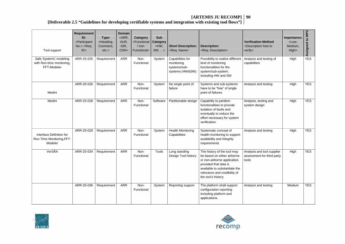
[ARTEMIS JU RECOMP] [Deliverable 2.5 “Guidelines for developing certifiable systems and integration with existing tool flows”]
90
Tool support
Requirement ID:
<Participant No.>-<Req.
ID>
Type: <Heading, Comment,
etc.>
Domain <ARR, AUR, IDR,
CDR>
Category <Functional
/ non-Functional>
Sub Category
<HW, SW, …>
Short Description: <Req. Name>
Description: <Req. Description>
Verification Method <Description how to verify>
Importance: <Low,
Medium, High>
Ass
ign
ed t
o W
P2
Safe SystemC modeling with Run-time monitoring,
FFT-Modeler
ARR-25-025 Requirement ARR Non-Functional
System Capabilities for monitoring systems/sub-systems (HW&SW)
Possibility to realize different kind of monitoring functionalities for the system/sub-system; including HW and SW
Analysis and testing of capabilities
High YES
Medini
ARR-25-026 Requirement ARR Non-Functional
System No single point of failure
Systems and sub-systems have to be “free” of single point of failures
Analysis and testing High YES
Medini ARR-25-028 Requirement ARR Non-Functional
Software Partitionable design Capability to partition functionalities to provide isolation of faults and eventually to reduce the effort necessary for system verification.
Analysis, testing and system design
High YES
Interface Definition for Run-Time Monitoring,FFT-
Modeler
ARR-25-029 Requirement ARR Non-Functional
System Health Monitoring Capabilities
Systematic concept of health-monitoring to support availability and integrity requirements
Analysis and testing High YES
VerSÅA ARR-25-034 Requirement ARR Non-Functional
Tools Long standing Design Tool history
The history of the tool may be based on either airborne or non-airborne application, provided that data is available to substantiate the relevance and credibility of the tool’s history
Analysis and tool supplier assessment for third party tools
High YES
ARR-25-036 Requirement ARR Non-Functional
System Reporting support The platform shall support configuration reporting including platform and applications.
Analysis and testing Medium YES

[ARTEMIS JU RECOMP] [Deliverable 2.5 “Guidelines for developing certifiable systems and integration with existing tool flows”]
91
Tool support
Requirement ID:
<Participant No.>-<Req.
ID>
Type: <Heading, Comment,
etc.>
Domain <ARR, AUR, IDR,
CDR>
Category <Functional
/ non-Functional>
Sub Category
<HW, SW, …>
Short Description: <Req. Name>
Description: <Req. Description>
Verification Method <Description how to verify>
Importance: <Low,
Medium, High>
Ass
ign
ed t
o W
P2
FFT-Modeler ARR-25-037 Requirement ARR Non-Functional
Safety The platform shall support exhaustive self–test function to support fault diagnosis in case of suspected faults. Process and monitoring process have to be segregated.
Analysis and testing of self-testing features and overall self-test strategy
Medium YES
ARR-25-038 Requirement ARR Non-Functional
System WCET The platform shall support WCET evaluation without code instrumentation.
Static analysis of task features in conjunction with platform/processor to determine WCET
High YES
LIME Concolic Tester ARR-25-039 Requirement ARR Non-Functional
System MC/DC support The platform shall support MCDC testing without code instrumentation.
Static analysis of task features in conjunction with platform/processor
Low YES
VerSÅA AUR-23-4 Requirement AUR Non-
Functional Process
ASIL D Conformed development according to ISO 26262.
Safety Integrity Level of ASIL D shall be considered during every further step of development
Check for following of product development and safety process. High YES
AutoFOCUS 3, VerSÅA
AUR-23-50 Requirement AUR Non-
Functional Tools Tools qualification.
Tools used for development of MCP shall show their compatibility in fulfilling 'Tooling requirements' as specified by ISO26262
Requirement for Tool supplier. Its up to their responsibility to qualify and certify their tool. Low YES

[ARTEMIS JU RECOMP] [Deliverable 2.5 “Guidelines for developing certifiable systems and integration with existing tool flows”]
92
Tool support
Requirement ID:
<Participant No.>-<Req.
ID>
Type: <Heading, Comment,
etc.>
Domain <ARR, AUR, IDR,
CDR>
Category <Functional
/ non-Functional>
Sub Category
<HW, SW, …>
Short Description: <Req. Name>
Description: <Req. Description>
Verification Method <Description how to verify>
Importance: <Low,
Medium, High>
Ass
ign
ed t
o W
P2
Assurance Case Editor
IDR-13-010 Requirement IDR Non-Functional
Process The Safety Life Cycle and relating activities used to develop multi-core systems shall comply with the guidelines set out within IEC 61508:2010 parts 1-4.
Check against each clause of the standard by independent assessor. Evidence of verification is done by compiling a Safety Case. The Safety Case contains the verification results of every lifecycle phase. The verification activities are planned in a Safety plan. Safety Plan and Safety Case are reviewed by an independent assessor.
High YES
Assurance Case Editor IDR-13-012 Requirement IDR Non-Functional
Process The Safety Life Cycle shall facilitate Safety Function development up to Safety Integrity Level of 3 according to IEC61508:2010.
Analysis, assessment of the Safety Case
High YES
IDR-13-038 Requirement IDR Non-Functional
Software As far as practicable the design shall keep the safety-related part of the software simple.
Analysis assessment of documentation code inspection static code analysis regarding coding guidelines
High YES

[ARTEMIS JU RECOMP] [Deliverable 2.5 “Guidelines for developing certifiable systems and integration with existing tool flows”]
93
Tool support
Requirement ID:
<Participant No.>-<Req.
ID>
Type: <Heading, Comment,
etc.>
Domain <ARR, AUR, IDR,
CDR>
Category <Functional
/ non-Functional>
Sub Category
<HW, SW, …>
Short Description: <Req. Name>
Description: <Req. Description>
Verification Method <Description how to verify>
Importance: <Low,
Medium, High>
Ass
ign
ed t
o W
P2
IDR-13-048 Requirement IDR Non-Functional
Tools Tools involved in the multi-core development life cycle shall comply with section 7.4.4 within part 3 of IEC 61508:2010.
Analysis, assessment of documentation
High YES

7 CONCLUSIONS
This section will include conclusions from the work regarding the use of the tools on the different domains. Some of
the tools are specific for some domains and others can be shared by some of them, however the level of readiness in
each domain might differ.
7.1 AEROSPACE DEVELOPMENT PROCESS
There are already operating systems and tools in place for developing multi-core applications. Although they haven’t
been adopted by avionics yet, methods like PharOS can provide sufficient safety assurance and isolation and bound
or reduce the non-determinism present in multi-core systems.
As the complexity of the system grows, the amount of tools and their functions will increase as well. Therefore one of
the key approaches to (re-)certification cost reduction is the tool qualification. When comparing the V-model in ISO
DIS 26262 to the typical life cycles in Aerospace, DO-178B has much more focus on verification.
Qualified tools are widely used in verification of airborne software; some tools are used in validation as well. On the
other hand, the tool qualification in development area (like code generators) is a rare situation. This is driven by
different requirements on tools which can insert errors and which can “only” fail to detect errors. If a tool can insert
an error, the qualification requirements in aerospace are identical to the requirements for airborne software. The
tool could have more requirements, source code and tests than the airborne application itself, which makes the tool
qualification more costly than the entire development project. If a tool can only fail to detect an error, the
qualification requirement is to demonstrate that the tool operates in accordance with its requirements in normal
operation. This means that it is necessary to specify requirements (what the tool is supposed to do), to define normal
range tests for these requirements and to execute them. No robustness tests or any other project artifacts are
necessary (even planning the qualification could be inserted into plans of the entire project and does not need to be
packaged separately). Experience shows that qualification of a verification tool typically requires one order less effort
than a qualification of a development tool of similar complexity. A good example is provided by the code generators,
that are often not qualified even though they produce a final source code; correctness of such code is subsequently
verified using an independent qualified verification tool.
7.2 TOOL QUALIFICATION AS MEANS FOR CERTIFICATION COST
REDUCTION IN AEROSPACE
To answer a question how any specific tool contributes to the certification cost reduction, we must first define what
the certification cost is.
If we define the certification cost as a sum of any added costs associated purely with fulfilling the additional legal
requirements imposed by certification authorities, we realize that it is not that significant in the aerospace domain as
expected. The certification basically includes the communication with certification authorities to provide sufficient
evidence that final product will operate according to the requirements and meets the agreed standards. The
emphasis is in the term provide evidence, because in the aerospace domain, design assurance phase already contains
all the necessary verification and validation steps and they would be performed even without certification.

[ARTEMIS JU RECOMP] [Deliverable 2.5 “Guidelines for developing certifiable systems and integration with existing tool flows”]
95
Introduction of any design or verification tool actually increases the certification cost in this case - additional
qualification cost are incurred.
If, on the other hand, we define the certification cost as also containing the respective parts of the design process
that provide the design assurance, there is a significant area for the process optimization. Proposed tools simplify,
enhance or change the design assurance part of the development process and therefore significantly contribute to
the reduction of the overall cost. A common misconception is that qualification is good for a single project only which
results in an incorrect goal is to require as few qualifications as possible. In fact, the regulatory requirements need a
tool re-qualification only when anything changes in the environment (tool chain). If the tool chain stays the same, all
the applicant needs to do is to state in the Plan for Software Aspects of Certification (PSAC) that the existing tool
qualification will be reused. This work package has identified suitable tool chains and once they will be first qualified,
the costs for individual users will be significantly reduced. All the development process and tools must be planned in
advance in avionics, (including full environment) and if a different tool or tool chain comes into play in the middle of
a project, it causes both significant delays and a special attention of certification authority related to the revision of
plans.
The two above paragraphs have driven the tool selection by RECOMP demonstrators as listed in section ¡Error! No se
encuentra el origen de la referencia.. The selected tools optimize various phases of the life cycle and most of them
do not require any qualification (Medini, Assurance Case Editor, Run-time monitoring for multi-core SoCs, AccuRev,
Code Collaborator, PR-QA, AStyle, Beyond Compare 3, MS Development Studio, CODEO, and under some
circumstances also Interface Definition for Runtime Monitoring). If a tool requiring qualification is selected to be used
within the tool chain, it is typically a well established tool where the qualification data are already available (Reqtify,
VectorCAST). Although the qualifications are not transferred from one project to another automatically, availability
of the qualification data will reduce the required investment and the applicant will benefit from using the tool. Lime
Concolic Tester can be used as an alternative to VectorCAST to measure structural coverage required by DO-178B –
which of them is more suitable needs to be assessed on case by case basis.
Next step to achieve the RECOMP goal – making multi-core systems certifiable - could be a proposal to certification
authorities how we propose to address specific challenges identified in RECOMP. In the future, the regulatory opinion
about a given approach could be specified in a certification review item (CRI), issue paper (IP) or a supporting
standard to DO-178C. If the planned multi-core projects will show in the PSAC how they will comply with a particular
CRI/IP, the system is likely to be certifiable.
7.3 INDUSTRIAL DEVELOPMENT PROCESS
In the industrial domain there were several demonstrator developed with the safety functions being designed and
implemented using a selected set of tools, operating systems and hardware platforms. The following describes the
common tool and process aspects found in the RECOMP industrial demonstrators.
The development process includes a system design requirement specification task where the developers need to
decompose the safety functions and to allocate them to subsystems (sensors, logic solvers, actuators, processors and
even to core-level). The decomposing of the subsystems usually goes further to element level. Although RECOMP

[ARTEMIS JU RECOMP] [Deliverable 2.5 “Guidelines for developing certifiable systems and integration with existing tool flows”]
96
tools and methods may not be specific to system design requirements phase we found a component-based modelling
tool such as AutoFocus-3 useful in addressing the modelling of the system. Such a tool is helpful towards certification
when handling complete models of safety systems and also to show the hierarchy of subsystems and the
interconnections of the systems.
Some demonstrators did additional work on requirements modelling and verification using a RECOMP tools by first
developing abstract specification models describing the whole system and then to verify the system properties
before any design activities. For Simulink models a contract-based verifier was also used to verify the functional
properties of the components with are intended to replace the units test in some extend. The system design phase
takes the high-level and possibly automatically-verified models as input and develops functional concrete
components ready to be automatically generated. Additional components such as diagnostics units are created or
detailed in this phase. We were able to describe the detailed control structure of the modelled safety functions with
the selected modelling tool and also model needed components such as diagnostics units so generally such a tool
was well-received by the industrial demonstrators.
The hardware platforms varied in the industrial domain and several approaches to generate the executable system
on the multi-core platform exists. The modelling tool supports so-called technical architectures by which the
hardware platform can be described in detail. A technical architecture describes the number of cores, the mapping of
sensors and actuators to these cores, the interconnection between the cores and also the connections between the
cores and shared memory. Some demonstrators developed detailed technical architectures and automatically
generated executable code on such a system. Others generated operating system (PikeOs) partitions and had a small
additional amount of manually written code to execute the generated safety functions. Based on the demonstrator
evaluations it seems that the flexibility offered in the generation the executable system is a must feature of the tool
set. Systems differ whether they have distributed private memory per core vs. the memory shared by the core and
different technical architectures are needed. Using mix of manual and generated code to derive the OS partitions
executed on multi-core hardware results in a different tool chain chosen for some RECOMP demonstrators.
7.4 TOOL QUALIFICATION AS MEANS FOR CERTIFICATION COST
REDUCTION IN INDUSTRY
The center piece of the tool chains for the RECOMP industry domain demonstrators was model-based AutoFocus-3.
This tool is basically a tool sub-chain providing seamless model-based development from requirements to multi-core
hardware platforms. It incorporates code generation for chosen deployment platform based on scheduling analysis.
The other tools integrated to AutoFocus-3 in the industrial demonstrators integrated were the additional tools to
model and verify the requirements before developing the system models in AutoFocus-3. Additional basic software
tools such as compiler with linker were also needed in the tool chain.
The combination of modelling tool and requirements verification and validation tools is able to make the integrated
tool chain safer. The modelling tool may have potential errors in correctly maintaining the system model and as the
counter-measure for the potential model corruption the model checking tools should be used. Errors in system
models discovered by system model verification tools provide extra guard against faults injected by modelling tool
due to model corruptions.

[ARTEMIS JU RECOMP] [Deliverable 2.5 “Guidelines for developing certifiable systems and integration with existing tool flows”]
97
The modelling tool and requirements verification and validation tools work on different presentations of the system
and additional work is needed to develop SimuLink or Event-B models. However this extra effort may be cost-
efficient as it reduces the qualification cost the modelling tool. Additional benefit from the system model verification
tools is that they could be used to safe-guard against unit testing tool having errors causing low coverage thus
potentially producing undetected errors.
Any tool malfunctioning in the AutoFocus-3 tool chain (modelling, code generation, scheduling analysis and
deployment) can cause the violation of safety requirements. However, the modelling tool qualification needs are
reduced by the combined use of requirements verification and validation tools thus positively affecting the
certification costs. Further work is needed to analyse the code generation, scheduling and deployment to find out the
suitable counter-measures for detecting potential errors in these tools. However, the fact that these are already
integrated in a same tool using the same system model presentations and common programming interfaces should
have a positive effect on tool qualification costs and thus on certification costs.
7.5 AUTOMOTIVE DEVELOPMENT PROCESS
The automotive area is covered by ISO 26262, which is an adaptation of IEC 61508 for the automotive industry. Risk is
determined based on customer risk by identifying the so-called Automotive Safety Integrity Level (ASIL) associated
with each undesired effects. Regarding the development process, compared to DO-178B which suggests a waterfall-
like approach, ISO 26262 provides more guidance and supports a typical V-model development process.
The automotive market is a mass market, which has enormous cost pressures. For example, if a manufacturer sells
one million vehicles, saving one euro for each vehicle shipped, would lead to one million euros savings. Due to this
reason, the safety solutions delivered in the automotive area have to be very cost effective. The increasing number
of ECUs in modern vehicles has led to more integration of functions in one ECU. The automotive area has been
leading this trend, with initiatives such as AUTOSAR (AUTomotive Open System ARchitecture), which, among other
things, facilitates the integration. RECOMP addresses AUTOSAR through the component model of AutoFocus3 and
the connection to CESAR.
The ISO26262 defines a work product called safety plan in which the safety responsible should indicate how the tools
are going to be used within the project and their need for qualification. During the whole projects, hazards will lead
the development.
Ten methods and tools in RECOMP are targeted towards the automotive area. For example, AutoFocus3 is a
complete development environment, which has been extended to consider ISO 26262 certification in RECOMP.
SimTA/S is a schedulability analysis tool which is mainly used in the automotive area, and which has been extended
to take into account the impact of multi-core communication on worst-case execution time analysis.

[ARTEMIS JU RECOMP] [Deliverable 2.5 “Guidelines for developing certifiable systems and integration with existing tool flows”]
98
7.6 TOOL QUALIFICATION AS MEANS FOR CERTIFICATION COST
REDUCTION IN AUTOMOTIVE
Tools are becoming more and more important in current software and system development, and tool usage can
significantly reduce development costs, e.g., due to the automation of manual tasks. However, this increases also the
threats that the tools can introduce errors into the products or fail to detect them. Therefore, current safety
standards require analyzing the tools in the development and verification process.
Due to the huge cost pressures of the automotive market, there have been many efforts to reduce (re)certification
costs. Related to RECOMP, the Tool Chain Analysis method developed in RECOMP by Validas AG has been developed
for the automotive ISO 26262 standard (although is applicable to other standards as well).
On the automotive domain, tools that were conceived to be used in other domains can be reused as the ISO26262
accepts as valid tool qualification from domains such as avionics or industry automation.
Most of the automotive-related methods and tools developed in RECOMP have been modeled using TCA, and the
analysis has been able to reduce the Tool Confidence Levels (TCL), thus reducing the qualification (and indirectly
certification) costs. Eleven methods and tools have been integrated into the automotive tool chain. Out of these,
eight are at TCL 1, one at TCL 2 and two at TCL 3.