D1571 Setup Utility for RX100S2 - Fujitsumanuals.ts.fujitsu.com/file/3283/d1571-bios-en.pdf · Your...
63
Description D1571 Setup Utility for RX100S2 English answers 2
Transcript of D1571 Setup Utility for RX100S2 - Fujitsumanuals.ts.fujitsu.com/file/3283/d1571-bios-en.pdf · Your...

Description
D1571 Setup Utility for RX100S2
English
answers 2

Dieses Handbuch wurde auf Recycling-Papier gedruckt. This manual has been printed on recycled paper. Ce manuel est imprimé sur du papier recyclé. Este manual ha sido impreso sobre papel reciclado. Questo manuale è stato stampato su carta da riciclaggio. Denna handbok är tryckt på recyclingpapper. Dit handboek werd op recycling-papier gedrukt.
Herausgegeben von/Published by Fujitsu Siemens Computers GmbH Bestell-Nr./Order No.: A26361-D1571-Z140-1-7619 Printed in the Federal Republic of Germany AG 0704 07/04
A26361-D1571-Z140-1-7619
D1571 Setup Utility for RX100S2 REFERENCE MANUAL
D1571 Setup Utility for RX100S2
REFERENCE MANUAL
Introduction
Using the BIOS Setup
Menus of the BIOS Setup
PC Lock
SystemLock
Flash BIOS update
Error messages
Index
July 2004 edition

Intel and Pentium are registered trademarks and MMX and OverDrive are trademarks of Intel Corporation, USA.
Microsoft, MS, MS-DOS and Windows are registered trademarks of Microsoft Corporation. Examples of Windows operating systems: Windows 95, Windows 98, Windows Me, Windows NT, Windows 2000, Windows XP.
PS/2 and OS/2 Warp are registered trademarks of International Business Machines, Inc.
Rambus, RDRAM and the Rambus Logo are registered trademarks of Rambus Inc. Direct Rambus, RIMM, SO-RIMM, and Direct RDRAM are trademarks of Rambus Inc.
All other trademarks referenced are trademarks or registered trademarks of their respective owners, whose protected rights are acknowledged.
Copyright � 2003
All rights, including rights of translation, reproduction by printing, copying or similar methods, in part or in whole, are reserved.
Offenders will be liable for damages.
All rights, including rights created by patent grant or registration of a utility model or design, are reserved.
Delivery subject to availability. Right of technical modification reserved.

Contents Introduction .....................................................................................................................................1 Notational conventions ......................................................................................................................1 Using the Setup Utility.....................................................................................................................3 Calling Setup Utility ...........................................................................................................................3
Calling the Boot the Boot Menu immediately .............................................................................4 Summary of Setup Utility Keys ..................................................................................................5
Operating Setup Utility.......................................................................................................................5 Main menu........................................................................................................................................7 System Time .....................................................................................................................................7 System Date......................................................................................................................................7 Diskette A..........................................................................................................................................8 Parallel ATA (Primary Master) ...........................................................................................................8
Type ..........................................................................................................................................9 Transfer mode ...........................................................................................................................9 LBA Translation .........................................................................................................................9 PIO Mode ..................................................................................................................................9 32 Bit I/O .................................................................................................................................10 Ultra DMA Mode ......................................................................................................................10
Boot Options....................................................................................................................................10 POST Errors ............................................................................................................................10 Keyboard Check ......................................................................................................................11 SM Error Halt ...........................................................................................................................11 Quick Boot...............................................................................................................................11 Quiet Boot ...............................................................................................................................11 Memory Testing.......................................................................................................................11 Boot Menu ...............................................................................................................................11 Boot Sequence ........................................................................................................................12 Multiboot for HD´s....................................................................................................................12
Advanced menu .............................................................................................................................13 Peripheral Configuration ..................................................................................................................14
Serial .......................................................................................................................................14 Serial Multiplexer .....................................................................................................................15 Floppy Type.............................................................................................................................15 Diskette Controller ...................................................................................................................15 Mouse Controller .....................................................................................................................15
PCI Configuration ............................................................................................................................16 Ethernet on Board....................................................................................................................16
PCI Device Embedded Promise SATA (only A10) ...........................................................................18 PCI IRQ Configuration .............................................................................................................19 PCI Slots Configuration ...........................................................................................................20
Advanced System Configuration......................................................................................................21 CPU Settings ...........................................................................................................................21
Power On/Off...................................................................................................................................24 Power On Source ....................................................................................................................24
Reset Configuration Data.................................................................................................................25 Secured Setup Configurations .........................................................................................................25 Multiprocessor Specification ............................................................................................................25 Windows 2003 EMS Function..........................................................................................................26 Large Disk Access Mode .................................................................................................................26
A26361-D1571-Z140-1-7619

Contents
Security.......................................................................................................................................... 27 Setup Password ...................................................................................................................... 27 System Password ................................................................................................................... 28 Set Setup Password................................................................................................................ 28 Set System Password ............................................................................................................. 28 Setup Password Lock.............................................................................................................. 29 System Password Mode.......................................................................................................... 29 SETUP Prompt ....................................................................................................................... 30 Virus Warning ......................................................................................................................... 30 System Load ........................................................................................................................... 30 Diskette Write ......................................................................................................................... 30 Flash Write.............................................................................................................................. 30
Server menu .................................................................................................................................. 31 O/S Boot Timeout ........................................................................................................................... 31
Mode....................................................................................................................................... 31 Timeout value ......................................................................................................................... 32
ASR&R Boot Delay (min) ................................................................................................................ 32 Power Cycle Delay (sec) ................................................................................................................. 32 Boot Retry Counter ......................................................................................................................... 32 Diagnostic System .......................................................................................................................... 32 Diagnostic PXE boot device ............................................................................................................ 32 Critical Temperature Monitoring ...................................................................................................... 32 Clear S stem Delay (sec)................................................................................................................ 33 yIPMI 33
IPMI Specification Version ...................................................................................................... 33 Clear System Event Log.......................................................................................................... 34 Event Log Full Mode ............................................................................................................... 34 Existing Event Log number...................................................................................................... 34 Remaining Event Log number ................................................................................................. 34 System Event Log................................................................................................................... 35 System Event Log (list mode) ................................................................................................. 36 Realtime Sensor Data ............................................................................................................. 37 Lan Settings ............................................................................................................................ 38
CPU Status ..................................................................................................................................... 39 Memory Status................................................................................................................................ 40
Channel A ............................................................................................................................... 40 Channel B ............................................................................................................................... 40
Console Redirection........................................................................................................................ 41 Console edirection Port ........................................................................................................ 41 RPort 41 Media Type ............................................................................................................................. 42 Console connection................................................................................................................. 42 Baud Rate ............................................................................................................................... 42 Protocol................................................................................................................................... 42 Flow Control ............................................................................................................................ 42 Mode ??? ................................................................................................................................ 42

Contents
Exit menu .......................................................................................................................................43 Save Changes & Exit.......................................................................................................................44 Discard Values &Exit .......................................................................................................................44 Get default values............................................................................................................................45 Load previous values.......................................................................................................................45 Save changes..................................................................................................................................46 D1571 A50 Differences ..................................................................................................................47 Main menu.......................................................................................................................................47
SATA Port 0/1..........................................................................................................................48 Boot Sequence ........................................................................................................................49
Advanced menu...............................................................................................................................50 PCI Configuration ....................................................................................................................51 S-ATA Interface .......................................................................................................................51 LSI SATA RAID .......................................................................................................................51
Error Messages..............................................................................................................................52 Index...............................................................................................................................................53
A26361-D1571-Z140-1-7619 3


Introduction
Most systems are already configures by the manufacturer or the dealer. There is no need to run the Setup Utility when starting the computer unless you get a Run Setup message. In Setup Utility you can set the system functions and the hardware configuration of the device. When it is supplied, the device is set to factory default settings. You can change these settings in Setup Utility. Any changes you make take effect as soon as you save the settings and quit the Setup Utility. You can select the following settings in the Setup Utility : Main Basic system information Advanced Further system information Security Security functions Server Server management Exit Save changes and exit Setup
i
The individual menus and setting options are described in chronological order in the next chapters. Since the setting options and menus depend on the hardware configuration of your device, some of them may not be offered in the Setup Utility.
Notational conventions The meanings of the symbols and fonts used in this manual are as follows:
!
Pay particular attention to texts marked with this symbol. Failure to observe this warning endangers your life, destroys the system, or may lead to loss of data.
i
Supplementary information, remarks, and tips follow this symbol.
► Text which follows this symbol describes activities that must be performed in the order shown. Ë This symbol indicates that you must enter a blank space (press the Space Bar) at this point. ↵ This symbol indicates that you must press the Enter key. Text in this typeface indicates screen outputs. Text in this bold typeface indicates the entries you make via the keyboard. Text in italics indicates commands or menu items. "Quotation marks" indicate names of chapters or terms.
i
In the menus, shown on the screen, the following conventions are availiable: White items can be changed. Blue items cannot be changed, they are fix!
A26361-D1571-Z140-1-7619 1


Using the Setup Utility
Calling Setup Utility ► Restart the device (switching On/Off or warm boot). The following message is displayed at the lower edge of the screen: F2: Enter Setup, F12: Boot Menu
► Press the F2 key to enter the Setup Utility. ► If you have assigned a supervisor password, you must now enter this password and confirm it
with the Enter key. The Main menu of Setup Utility is displayed on the screen:
Setup Utility Main menu of D1571 A10 BIOS setup
i
In this manual two types of the Board D1571 are described, D1571 A10 and D1571 A50.
D1571 A10 is the mainboard with hot plug function, D1571 A50 is the mainboard without hot plug function. First, the D1571 A10 BIOS setup is described.
In the last chapter (see chapter �D1571 A50 Differences�), the differences of D1571 A50 in comparison to D1571 A10 are described.
A26361-D1571-Z140-1-7619 3

Using the Setup Utility
Item Specific Help By pressing the F1 key,the item help in the bottom of the screen appears. There you can get detailed information about the items.
Example of item specific help (A10)
Calling the Boot the Boot Menu immediately
i
You may use this function if you do not want to boot the system from the drive specified as first device in the entry Boot Sequence in the submenu Boot Options.
► Press function key F12 . After a while, the Boot Menu appears as pop up window on the screen.
► Select, from which drive you want to boot the operating system. The selection options are the same as in the submenu Boot Options of the Stup Utility main menu. Your selection is only valid for the current system boot. At the next system start, the options selected in the entry Boot Sequence in the submenu Boot Options are valid again.
4 A26361-D1571-Z140-1-7619

Using the Setup Utility
► Use the arrow keys → or ← to select from which drive you want to boot the system now and
press the Enter key. ► If you want to call the Setup Utility, use the arrow keys ↑ or ↓ to select the Setup and press
the Enter key. Your computer supports three Setup Utility levels. The above screen is the Setup Utility Basic Level screen. This allows you to view and change only the basic configuration of your computer.
Summary of Setup Utility Keys In the following table a summary of the function of keys, availiable in the Setup Utility, is given:
Tape Key Function ↑ or ↓
Select item
The highlight bar moves up and down and marks an item in the Setup Utility main menu or in a submenu, which you acitvate by pressing Enter .
← or →
Select Menu
The the highlight bar moves and marks a submenu or a value which you acitvate by pressing Enter .
Enter
Enter
The entered values become effective.
Esc
Exit
The Setup Utility main menu, alternatively any other menu, it quit. If you are in a submenu, you return to the Setup Utility main menu. If you are already in the main menu, pressing this key allows you to exit the Setup Utility.
F1
Info
The item specific help on the right-hand side of the sreen is switched on or off.
F2
Enter Setup
Setup Utility is entered while booting the device.
F12
Call Boot Menu
Boot menu is called immedeately
+ / -
Change Values
A value increases or decreases by press + or - .
Operating Setup Utility ► To select an item in the Setup Utility main menu, move the highlight bar by using the cursor
keys ↑ or ↓ and then press Enter .. ► To change the entry for the selected field, press the cursor keys ← or → until the desired
setting is found.
i
If you change entries in the Setup Utility, make a note of the changed entries!
A26361-D1571-Z140-1-7619 5


Main menu The following screen appears if you select the menu Main from the Setup Utility:
Setup Utility Main menu of D1571 A10 BIOS setup
System Time indicates the time of the device. The time is shown in the format "hours:minutes:seconds". ► If you want to change the current time set, use the cursor keys ↑ or ↓ to move to the field to
be changed and press ← or → until you get the desired value.
!
If the settings in the Time and Date fields are frequently wrong when you power up the computer, the lithium battery is dead. Replace the battery.
System Date indicates the date of the device. The date is shown in the format "weekday-month-day-year". ► If you want to change the current date set, use the cursor keys ↑ or ↓ to move to the field to be
changed and press ← or → until you get the desired value.
!
If the settings in the Time and Date fields are frequently wrong when you power up the computer, the lithium battery is dead. Replace the battery.
A26361-D1571-Z140-1-7619 7

Main menu
Diskette A Different entries are possible in this menu: 720KB 3.5-inch, 1.44 MB 3.5-inch (default), 2.88 MB 3.5-inch The entry depends on the floppy disk drive installed None No floppy disk drive installed or floppy disk drive is accessed via IDE Drive.
Parallel ATA (Primary Master) You can configure the hard disk drive connected to the master port of the parallel IDE channel 1. ► Call the submenu Parallel ATA (Primary Master) to make corresponding settings of the the
parallel ATA hard disk drive. If your system board has just one connector for IDE drives, you can only enter settings for the parallel IDE Primary Master
Parallel ATA (Primary Master) menu of D1571 A10 BIOS setup and D1571 A50 BIOS setup
i
You should change the default settings only if you are connecting an additional IDE drive to the IDE connector. The maximum transfer rate of two IDE drives connected to the same connector is determined by the slowest one. Fast hard disks should therefore be connected to the first IDE connector and identified as Parallel ATA (Primary Master). In the case of system boards with newer controllers, all IDE drives are supported independently and configured for the maximum transfer rate. This means that a fast and a slow IDE drive can be connected to one connector without impeding the speed of the fast drive.
8 A26361-D1571-Z140-1-7619

Main menu
Type indicates, which type of hard disk is installed in the system User You enter parameters of hard disk drive installed at this connection. Auto autotypes hard drives are installed in the system (default). CD-ROM a CD-ROM drive is installed in the system. ATAPI Removable a removable disk drive is installed in the system None no hard disk installed
Transfer mode This field specifies the number of sectors per bloc for multiple sector transfers. Enabled The transfer is activated, one block is transferred for each interrupt. Disabled The transfer is not activated (default).
LBA Translation This item allows to set the addressing on consecutive sector numbers (LBA = Logical Block Addressing). LBA Translation converts the physical formatting of hard disks in cylinders, heads and sectors so that the logical values generated lies within the above BIOS limitations. This means that a hard disk capacity of over 528 Mbyte can be supported. Operating systems and application programmes work with these logical hard disk values. IDE hard disks of over 528 Mbyte are configured and operated using LBA mode. If a hard disk supports LBA mode, you can use the full capacity of the IDE hard disk.
! Change the default entries only if you are installing another hard disk drive.
Enabled If the hard disk supports LBA and it has a capacity of more than 528 Mbytes, the BIOS translates the hard disk parameters, allowing the disk's full capacity to be used. This allows the disk's full capacity to be used.
Disabled The BIOS uses the hard disk parameters and supports a maximum capacity of 528 Mbytes (default)
PIO Mode The PIO (Programmed Input Output) mode defines the transfer rate of the IDE hard disk drive. If at all possible use the entry Auto in the field Type. This means BIOS will determine the best possible transfer rate for the hard drive. If transfer rates are set incorrectly, the hard drive will be either too slow (i. e. the hard disk has a higher transfer rate then the one that was set) or the hard drive does not boot correctly, or does not respond (i. e. the hard drive is set to a higher transfer rate then it is capable of). Fast PIO 1(default), Fast PIO 2, Fast PIO 3, Fast PIO 4, FPIO3/DMA1, FPIO4/DMA2 .
A26361-D1571-Z140-1-7619 9

Main menu
32 Bit I/O permits 32 bit IDE transfer rate Enabled enables this function Disabled disables this function (default)
Ultra DMA Mode specifies a fast Ultra DMA transfer mode for the IDE hard disk drive. Disabled The fast Ultra DMA transfer mode is not set (default). Mode 0, 1, 2 The fast Ultra DMA transfer mode is set.
Boot Options
Boot Options menu of D1571 A10 BIOS setup and of D1571 A50 BIOS setup
POST Errors defines whether the system start-up is to be aborted and the system halted when an error is detected. Enabled If the self-test detects an error, system start-up is aborted after the self-test, and the
system is halted. Disabled The system start-up is not aborted. The error is ignored as far as possible (default).
10 A26361-D1571-Z140-1-7619

Main menu
Keyboard Check specifies whether keyboard checks are carried out. This setting is useful for systems which are operated without a keyboard. Enabled Keyboard checks are carried out. If there are keyboard faults, the system behaves as
defined in the setting in the POST Errors menu item. Disabled No keyboard checks are carried out. Possible keyboard faults are not detected
(default).
SM Error Halt Error Handling for System Monitoring, configures the system behaviour during the self-test in case of a system monitoring error reported by the BMC (e.g. fan monitoring, temperature monitoring). This setting is only effective when the setting Halt On All Errors or Enabled has been selected in the Post Errors menu. Enabled If an error is reported to the BIOS by the BMC, the system start-up is cancelled and
the system stopped following the self-test. Disabled The system start is not cancelled when an error is reported to the BIOS by the BMC.
(default).
Quick Boot can reduce the extent of the self-test to accelerate the system start-up. Enabled When the device is switched on, the quick self-test is carried out, in which the floppy
disk drives are not checked (default). Disabled When the device is switched on, the complete device configuration is tested.
Quiet Boot minimises startup display during boot. Enabled The logo is displayed on the screen. A switch to the POST information is made if you
press the F3 or the Esc key or if errors occur. Disabled No logo, but only the POST information is displayed on the screen (default).
Memory Testing defines whether a memory test is run or not. Enabled The memory test is carried out during the boot routine of the BIOS. Disabled The memory test is not carried out during the boot routine of the (default).
Boot Menu specifies whether the BOOT menu can be invoked with F12 during the POST. Enabled The Boot menu can be invoked. Disabled The Boot menu cannot be invoked (default).
A26361-D1571-Z140-1-7619 11

Main menu
Boot Sequence specifies the sequence of the system files that the system BIOS requires during booting. This sequence can be changed with the cursor.
Boot Sequence menu of D1571 A10 BIOS setup
CD-ROM Drive If an ATAPI CD-ROM drive is installed, this entry enables you to boot from the CD-ROM drive.
Removable Devices Here, several removable devices can be chosen for booting the system.
Hard Drive The system is booting from hard disk
Multiboot for HD´s Determines Hard Drive should be used or not. Enabled The menu item Hard Drive specifies the boot sequence. Disabled The menu item Hard Drive cannot affect the boot sequence. Scan order is used as
boot order.
12 A26361-D1571-Z140-1-7619

Advanced menu The Advanced menu calls the submenu in which you can make additional settings.There are different screens, depending on whether a hot plug board is installed or a non hot plug board is installed. ► To view the Advanced Level, select the Advanced menu from the Setup Utility main menu.
!
Change the default settings only for special applications. Incorrect settings can cause malfunctions.
► Select Peripheral Configuration to set the Peripheral Configuration settings. ► Select PCI Configuration to set the PCI Configuration settings. ► Select Advanced System Configurations to set the Advanced System Configurations settings.
The following screen appears if you select Advanced from the Setup Utility main menu, when a hot plug mainboard is installed:
Advanced menu of D1571 A10 BIOS setup
A26361-D1571-Z140-1-7619 13
Advanced menu
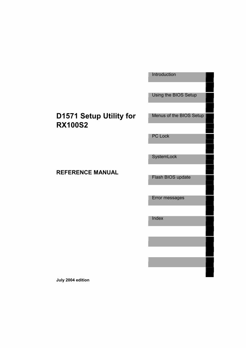
Peripheral Configuration displays the serial port configuration.
Peripheral Configuration menu of D1571 A10 BIOS setup
Serial This field selects the address and the interrupt used to access the relevant serial port. Enabled The serial port is set to the shown address and interrupt. If you set Enabled,
additional lines are displayed for setting the configuration. Auto The serial port is automatically set to the next available combination (address,
interrupt). Disabled The serial port is disabled (default).
14 A26361-D1571-Z140-1-7619

Advanced menu
Serial Multiplexer specifies whether the serial interface can be used by the system or the BMC. System The serial interface can be used by the system or the operating system. BMC The serial interface can be used by the BMC. The operating system cannot use the
serial interface (default). Shared The serial interface can be used by both, BMC and system
Floppy Type Specifies which floppy disk drive controller is to be used. It is possible to choose from the local (default) controller and the controller for remote access. The default controller permits access to the floppy disk drive installed in the system. On the other hand, the controller for remote access permits access to a floppy disk drive of another system or to a floppy-disk image file stored on another system. The data are routed via the network in this case. Local The default floppy-disk drive controller of the system is used (default). Remote The floppy-disk drive controller for remote access is used. Remote Once The floppy-disk drive controller for remote access is used for the subsequent system
start-up. Then the system automatically switches over to Local.
Diskette Controller This field is used to enable and disable the built-in floppy disk controller on the system board. Enabled The floppy disk controller is enabled - IRQ 6 is used. Disabled The floppy disk controller is disabled - IRQ 6 is free.
Mouse Controller This field is used to enable and disable the built-in mouse controller on the mainboard. Auto Detect The connected mouse is automatically detected and activated. Operating systems
that support Plug&Play automatically configure the mouse. Enabled The mouse controller is enabled - IRQ 12 is used. Disabled The mouse controller is disabled - IRQ 12 is free.
A26361-D1571-Z140-1-7619 15

Advanced menu
PCI Configuration The PCI configuration invokes the submenu where you can make settings for the PCI devices (PCI slots and PCI components on the mainboard). Also in this submenu there are differences between the values of a hot plug board and of a non hot plug board. With hot plug the following screen appears:
PCI Configuration submenu of D1571 A10 BIOS setup
Ethernet on Board determines whether the first network controller on the system board is used or not (Ethernet on Board).
16 A26361-D1571-Z140-1-7619

Advanced menu
Enabled The first network controller on the system board is enabled. Disabled The first network controller on the system board is disabled.
PCI Device, Embedded Ethernet 1/2
Device determines whether or not the LAN controller on the mainboard is used. Enabled The LAN controller on the mainboard is enabled. Disabled The LAN controller on the mainboard is disabled (default).
Option ROM Scan specifies whether the BIOS of the adapter in this PCI slot is started by the system BIOS. To load an operating system from an adapter (e.g. SCSI, LAN), the related adapter must be controlled by a BIOS. Enabled If the adapter in the PCI slot is equipped with a BIOS, this will be started during
initialisation by the system BIOS. Disabled The BIOS of the adapter is not started (default).
Bus Master specifies whether or not the PCI slot acts as a busmaster. Enabled The PCI slot acts as a busmaster. Disabled The PCI slot does not act as a busmaster (default).
Latency Timer 0040h Number of clock cycles (default) The field defines the additional number of clock cycles in which a burst can be transferred on the PCI bus over and above what is specified. n stands for the number of the PCI slot. N= 20h, 40h, 60h, 80h, A0h, C0h, E0h,
A26361-D1571-Z140-1-7619 17

Advanced menu
PCI Device Embedded Promise SATA (only A10) Here you can decide to enable or to disable this PCI device. This item appears only, when a hot plug board is installed.
Embedded Promise SATA menu of D1571 A10 BIOS setup
Device This function activates or desactivates this PCI device on Board. The default is dependent on the connected hardware Enabled activates promise controller (default value, when it is a hot plug board) Disabled deactivates promise controller.
Bus Master Enables or disables a selcted device as a PCI bus master. Enabled The selcted device acts as a busmaster. Disabled The selcted device does not act as a busmaster (default).
Latency Timer 0040h Number of clock cycles (default) The field defines the additional number of clock cycles in which a burst can be transferred on the PCI bus over and above what is specified. n stands for the number of the PCI slot. N= 20h, 40h, 60h, 80h, A0h, C0h, E0h,
18 A26361-D1571-Z140-1-7619

Advanced menu
PCI IRQ Configuration calls the submenu in which you can make the settings for the PCI interrupts. The submenu may have a scroll bar depending on the number of PCI interrupts.
PCI IRQ Line 0/VGA Sets PCI IRQ mapping. This line is connected to VGA INT A. A PCI device cannot use IRQ´s already in use by ISA devices. Auto A plug and play compliant configuration is set.
PCI IRQ Line 1/Ethernet 2 Sets PCI IRQ mapping. This line is connected to Ethernet 2 INT A. A PCI device cannot use IRQ´s already in use by ISA devices. Auto A plug and play compliant configuration is set.
A26361-D1571-Z140-1-7619 19

Advanced menu
PCI Slots Configuration calls the submenu in which you can make the settings for the PCI slots. The submenu may have a scroll bar depending on the number of PCI slots.
PCI Slot 1/2 Cofiguration
Option ROM Scan specifies whether the BIOS of the adapter in this PCI slot is started by the system BIOS. To load an operating system from an adapter (e.g. SCSI, LAN), the related adapter must be controlled by a BIOS. Enabled If the adapter in the PCI slot is equipped with a BIOS, this will be started during
initialisation by the system BIOS. Disabled The BIOS of the adapter is not started.
Bus Master specifies whether or not the PCI slot acts as a busmaster. Enabled The PCI slot acts as a busmaster. Disabled The PCI slot does not act as a busmaster
Latency Timer The field defines the additional number of clock cycles in which a burst can be transferred on the PCI bus over and above what is specified. n stands for the number of the PCI slot. Number of clock cycles 0h, 40h, 60h, 80h, A0h, C0h, E0h, Default (40h)
20 A26361-D1571-Z140-1-7619

Advanced menu
Advanced System Configuration calls the submenu in which you can make additional settings.
CPU Settings
CPU Settings submenu of D1571 A10 BIOS setup
A26361-D1571-Z140-1-7619 21

Advanced menu
CPU Mismatch Detection Enabled Enables detection of CPU frequency change and front side bus frequency mismatch
(default). Disabled Disables detection of CPU frequency change and front side bus frequency mismatch.
Hyper Threading Hyper-threading technology allows a single physical processor to appear as several logical processors. With this technology the operating system can better utilise the internal processor resources, which in turn leads to increased performance. The advantages of this technology can only be used by an operating system that supports ACPI (The Advanced Configuration and Power Interface Specification, Revision describes the structures and mechanisms necessary to design operating system-directed power management and make advanced configuration architectures possible). This setting has no effect on operating systems that do not support ACPI. Enabled An ACPI operating system can use all logical processor within a physical processor
(default). Disabled An ACPI operating system can only use the 1st logical processor of the physical
processor. This setting should only be used if hyper-threading technology has not been correctly implemented in the ACPI operating system.
L3 Cache Enabled Enables the third-level cache memory incorporated in the CPU module (default). Disabled Deactivates this function.
Delay prior to Enabling the TCC Configures the time value for Thermal Control Cirquit (TCC) enable 0~30 min: default = 6 min
Fast String Operations This is an adjustment option of the CPU to effect optimised string operations. Cache procedures are optimised and interrupts are only admitted on cacheline boundaries.
i
On the Internet under www.intel.com in the document "IA-32 Intel Architecture Software Developers Manual Vol 1-3" under the keyword "Out-of-Order Stores for String Operations" you will find more information.
Enabled Activates the fast string operation function of the CPU (default). Disabled Deactivates the fast string operation function of the CPU.
22 A26361-D1571-Z140-1-7619

Advanced menu
Compatible FPU Code
i
On the Internet under www.intel.com in the document "IA-32 Intel Architecture Software Developers Manual Vol 1-3" under the keyword ""Guidelines for writing x87 FPU Exception Handlers" you will find more information.
Enabled Activates P6 the compatible FPU opcode register model Disabled Deactivates P6 the compatible FPU opcode register model (default).
Split Lock Operations This feature describes, whether during a transaction which splittes a acheline or a page (split-lock transaction) an allignment check exception is activated. Enabled Activates the split lock feature of the CPU Disabled Deactivates the split lock feature of the CPU (default).
Adjacent Sector Prefetch enables a prefetch to adjacent sectors. Enabled This has the effect that the CPU only reads complete cache lines (default). Disabled This has the effect that only the sector of a cacheline ,which contains the required
data, is read.
!
With this option you can make performance settings for exceeding applications. Fujitsu Siemens recommends for standart applications not to deviate from the default settings.
APIC Advanced Programmable Interrupt Controller controls multiprocessor functionality.
i
Some OS (e.g. Novell 3.12) require the APIC to be disabled
A26361-D1571-Z140-1-7619 23

Advanced menu
Power On/Off displays the serial number of your system board.
Power On Source specifies whether the system can be switched on via a connected device.
Remote specifies whether the system can be switched on by an incoming message (via an external device, e.g. modem, fax or telephone). The signal can be supplied externally via serial port 1 or internally via the modem on connector. Enabled The system can be switched on by an incoming message. Disabled The system cannot be switched on by an incoming message.
Resume On Time On The system is waked up after a soecial time. Off The system is not waked up.
Resume Time Condition: Resume On Time is On. Here you can set the exakt time for waking up the system.
24 A26361-D1571-Z140-1-7619

Advanced menu
LAN determines whether the system can be switched on by means of an LAN controller (on the mainboard or additional board). Enabled The system can be switched on by means of an LAN controller. Disabled The system cannot be switched on by means of an LAN controller.
Power Failure Recovery Here you can decide in which state the system shall return. Always Off the system ist shut down (default). Always On the system is restarted. Last State: the system returns to the last state.
Reset Configuration Data This field specifies whether the configuration data is reset and reinitialised when the system is started. Yes After the system is started, the configuration data is reset, and the entry in this field
is set to No. The new configuration data is determined by means of the Plug&Play functionality. The mounted boards and drives are then initialised with this data. Non-Plug&Play components must be entered manually (e.g. Windows, ICU).
No After the system is started, the Plug&Play functionality ascertains the current configuration data and uses this data to initialise the installed boards and drives. The configuration data of non-Plug&Play components are not reset.
Secured Setup Configurations Yes prevents a Plug and Play Operation System from changing system settings. No deactivates this function.
Multiprocessor Specification specifies which version of the multiprocessor table is used. The multiprocessor table is needed by multiprocessor operating systems to recognise the multiprocessor characteristics of the system. 1.4 The newer version of the multiprocessor table is used. 1.1 The older version of the multiprocessor table is used. You should use this setting
only if the operating system has problems with the multiprocessor configuration.
A26361-D1571-Z140-1-7619 25

Advanced menu
Windows 2003 EMS Function Components in the Windows Server 2003 family of operating systems, suc as the Windows loader, can provide Emergency Management Services console redirection. Console redirection makes video output appear in text format when sent to the out-of-band port and the local monitor, if one is attached, The computer continues to receive keyboard input from the out-of-band port and the local keyboard, if attached. While the OS is booting, the console takes over redirection from the firmware. Enabled The function is activated (default). Disabled The function is deactivated.
Large Disk Access Mode specifies the type of hard disk access for large hard disks (more than 1024 cylinders, 16 heads). The default setting depends on the operating system used.
i
If you are installing a new software and the drive fails, change this selection and try again. Different Operating Systems require different representations of drive geometries
DOS the operating system uses MS-DOS-compatible hard disk accesses. Other If the operating system uses hard disk accesses which are not MS-DOS-compatible
(e.g. Novell, SCO Unix).
26 A26361-D1571-Z140-1-7619

Security The Security menu offers you various options for protecting your system and personal data from unauthorized access. By combining these options, you can achieve maximum protection for your system: • Preventing unauthorized Setup Utility entry
You can activate this protection by setting a setup (supervisor) password in the Security menu. • Preventing unauthorized system access
You can activate this protection by setting a system (user) password in the Security menu. • Virus Warning • Preventing unauthorized writing of disk drives • Flash Write Protection
Setup Password Installed a setup password is set. Not installed a setup password is not already set or is deleted.
A26361-D1571-Z140-1-7619 27

Security
System Password Installed a system password is set. Not installed a system password is not already set or is deleted.
Set Setup Password To change the setup password, proceed as follows: ► Call the Setup Utility. ► Select the Security menu. ► Select the Set Setup Password item. • Press Enter to display the Set Setup Password menu. The following screen appears:
The setup password is set. The value of the item Setup Password changes to Installed.
i When you enter a blank instead of a new user password, the old user password is deleted! Then the value of the item Setup Password changes to Not installed
Set System Password Condition: Setup Password is set. To change the system password, proceed as follows: ► Call the Setup Utility. ► Select the Security menu. ► Select the Set System Password item. • Press Enter to display the Set System Password menu. The following screen appears:
28 A26361-D1571-Z140-1-7619

Security
► Type the new password and press Enter ► Retype the new password and press Enter . The setup password is set. The value of the item System Password changes to Installed. Now, the system password is ordered every time when you enter Setup.
i When you enter a blank instead of a new user password, the old user password is deleted! Then the value of the item System Password changes to Not installed
Setup Password Lock With this setting you can prevent an unauthorized access to the settings of devices with its own BIOS. An Adapter BIOS can be branched or not. Condition: Setup password has been set Standard: to process boot without Adapter BIOS locked. The setup password is deactivated
when booting (default) Extended: to process boot with Adapter BIOS locked. To enter the Adapter BIOS-Setup is
impossible.
System Password Mode Condition: Setup and system password are installed. This field establishes the effect of the system password. System Boot process will be suspended until the system password is entered.
i To disable both features uninstall the system password.
A26361-D1571-Z140-1-7619 29

Security
SETUP Prompt To activate this protection, select the item Setup Prompt in the Security menu Enabled The prompt F2: Enter Setup is displayed on the screen while booting. Disabeld The prompt F2: Enter Setup is not displayed on the screen while booting.
Virus Warning Allows you to check your hard disk boot sectors each time when system is powered on. You will be warned about all changes an must confirm to acknoledge the warning. Normal, Write Protect
System Load Standard this value is fix and not changeable.
Diskette Write To activate this protection, select the item Diskette Write in the Security menu. Enabled acitvates diskette write protection (default) Disabeld deacitvates diskette write protection
Flash Write To activate this protection, select the item Flash Write in the Security menu Enabled no BIOS write protection (default) Disabeld acitvates BIOS write protection
30 A26361-D1571-Z140-1-7619

Server menu The Server menu provides the basic management function for administrator.
O/S Boot Timeout The O/S Boot Timeout supervises the OS booting process. If there is an error during the OS boot phase, the booting process is aborted and a log message is written. Enabled enables OS Boot Timeout during the OS boot phase. Disabled: Disables OS Boot Timeout function (default).
Mode Specifies the action that takes place after the boot watchdog has expired. Continue the system continues booting.
Hard Reset: the system is shut down and restarted (warm boot) default. Power Cycle: the system is switched off and restarted after waiting a moment (cold boot).
A26361-D1571-Z140-1-7619 31

Server menu
Timeout value determines the O/S Boot Timeout function and time, the maximum time, after which Bott Watchdog has to run. Within this time the operating system has to be loaded, if not, the Boot Watchdog intervenes. 1-99 min: select the desired boot watchdog time 0 Disables the boot watchdog function (default).
ASR&R Boot Delay (min) ASR&R stands for Automatic Server recovery and Reboot. It defines the time when system is powered on again due to shut down caused by a critical condition.
Power Cycle Delay (sec) This setup item defines the minimum time in seconds between power off and consecutive power on. 0~15 sec
Boot Retry Counter A Boot Retry Counter is a counter which counts the number of aborted boot processes. 0, 1, 2, 3 (default), 4, 5, 6, 7
Diagnostic System After specified boot retries switch off system or start Diagnostic System at next boot from IDE Hard Disk, LAN or Remote Image Disk. LAN, Remote Image Disk Disabled the Diagnostic System is not activated.
Diagnostic PXE boot device In this setup item you can select the number of rebootings from PXE of the system. 0, 1, 2, 3 (default), 4, 5, 6, 7, 8, 9, 10, 11, 12, 13, 14, 15, 16
Critical Temperature Monitoring Monitors the system, if temperature reaches a critical value. Enabled system switches off when critical temperature is reached. Disabled: Disables this function (default).
32 A26361-D1571-Z140-1-7619

Server menu
Clear System Delay (sec) It is the Delay time (sec) before clear screen on boot. 0 no delay 1-31
IPMI The IPMI menu opens the submenu with the IPMI (Intelligent Platform Management Interface) settings. The behaviour of the BMC (Baseboard Management Controller) is specified and information displayed here.
IPMI Specification Version indicates the IPMI version.
BMC Firmware indicates the version of the Baseboard Management Controller (BMC) firmware.
A26361-D1571-Z140-1-7619 33

Server menu
Clear System Event Log Enabled forces the BIOS to clear the System Event Log during the next cold boot. Disabled disables this function (default).
Event Log Full Mode This item allows the user to decide what happens with the event logs when the event log area is full. Maintain: event loggin stopps, if the SEL is full. Overwrite: event logging continues, even if the SEL is full. The oldest entry will be overwritten
(default).
Existing Event Log number specifies the number of entries in the Event Log. 0-254
Remaining Event Log number Displays the number of remaining entries in the Event Log. 0-254
i The number of existing event logs and remaining event logs are total 254
34 A26361-D1571-Z140-1-7619
Server menu
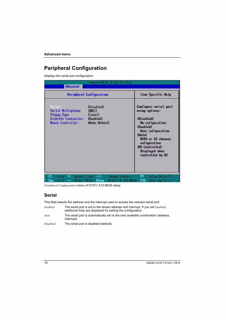
System Event Log This item displays the events with some properties like timestamp, type, data etc.
A26361-D1571-Z140-1-7619 35

Server menu
System Event Log (list mode) This option lists the system event log files for viewing.
36 A26361-D1571-Z140-1-7619

Server menu
Realtime Sensor Data There are sensors on the board for monitoring temperature and voltage. This item displays the values of temperature and voltage.
A26361-D1571-Z140-1-7619 37

Server menu
Lan Settings
Local IP Adress Information to see the BMC IP address
Subnet Mask Information to see the BMC subnet mask. It is recommended to use the same Subnet Mask you have specified on the OS Network for the used network card.
Gateway Adress Information to see the BMC Gateway address. It is recommended to use the same Gateway address you have specified on the OS Network for the used network card
User ID 1 Password The password for the authentication of the default user. To write the password to the BMC, press Enter .
38 A26361-D1571-Z140-1-7619

Server menu
CPU Status If a CPU is failed but equipped, the Service Processor has stopped the CPU on demand or due to CPU errors.Status of empty CPU slot ist unchangeable. The Boot Strap CPU(*) is marked.
Disabled CPU error has occured Enabled default
A26361-D1571-Z140-1-7619 39
Server menu
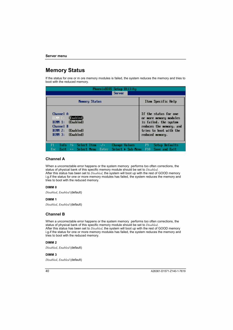
Memory Status If the status for one or m ore memory modules is failed, the system reduces the memory and tries to boot with the reduced memory.
Channel A When a uncorrectable error happens or the system memory performs too often corrections, the status of physical bank of this specific memory module should be set to Disabled. After this status has been set to Disabled, the system will boot up with the rest of GOOD memory i.g.if the status for one or more memory modules has failed, the system reduces the memory and tries to boot with the reduced memory.
DIMM 0 Disabled, Enabled (default)
DIMM 1 Disabled, Enabled (default)
Channel B When a uncorrectable error happens or the system memory performs too often corrections, the status of physical bank of this specific memory module should be set to Disabled. After this status has been set to Disabled, the system will boot up with the rest of GOOD memory i.g.if the status for one or more memory modules has failed, the system reduces the memory and tries to boot with the reduced memory.
DIMM 2 Disabled, Enabled (default)
DIMM 3 Disabled, Enabled (default)
40 A26361-D1571-Z140-1-7619

Server menu
Console Redirection This option allows the user to remote monitoring and controlling the BIOS by client computer.
Console Redirection Port Enabled Activates the Console Redirection function. Disabled Deactivates the Console Redirection function. (default).
Port Serial (Embedded) Cannot Change This option allows the user to remote monitoring and controlling the BIOS by client computer. Enabled Activates the Console Redirection function. Disabled Deactivates the Console Redirection function. (default)
i
If Console Redirection is set to Enabled, the user is allowed to adjust the options of Baud Rate and C.R after Post.
A26361-D1571-Z140-1-7619 41

Server menu
Media Type Selects the media for Console Redirection Serial: Serial data transfer refers to transmitting data one bit at a time. Lan: Lan is capable of transmitting data at very fast rates, much faster than data can be
transmitted over a telephone line
Console connection Indicates whether the console is connected directly to the system or a modem. Direct Console is connected directly to the system. via modem: Console is connected via modem to the system.
Baud Rate Select the transfer speed that is supported by your terminal application. 300, 1200, 9600 (default value) , 19.2k, 38.4k, 57.6k, 115.2k
Protocol Select the protocol that is supported by your terminal application VT100, VT100, 8bit, PC-ANSI, 7bit, VT100+ (default value), VT-UTF8
Flow Control Selects the flow control that is supported by your terminal application . None There is no flow control Xon/Xoff type of hardware flow control CTS/RTS type of hardware flow control
Mode Detemines whether console redirection continues during the OS loading process or not. Enhanced Console redirection continues during the OS loading process. Standart Console redirection does not continue during the OS loading process. The terminal operating mode is only available during the boot process.
42 A26361-D1571-Z140-1-7619

Exit menu When you have changed all of the set values in the BIOS setup, you should save your changes and exit BIOS setup program. There are two possibilities to exit Setup. ► select Exit from the menu bar. or ► press Esc when you are in the first level of Setup menus (Main, Advanced, Security, Server) The following submenu appears:
Here you can select the way, you want to exit Setup, either via changing all values or via discarding all values or via loading previous values or via getting default values.
A26361-D1571-Z140-1-7619 43

Exit menu
Save Changes & Exit Condition: Setup Utility settings have been changed This option allows user to exit system setup with saving the changes. ► press Esc to exit Setup or ► Press Enter on the Exit menu and select the item Save Changes& Exit You get the following confirmation message:
► Press Yes to save all the present setting values than user made in this time into CMOS. ► Press No to return to setup utility. ► Select Yes to save your changes before you exit Setup or No to discard all changes and return
to Setup. Therefore, when you boot up your computer next time, the BIOS will re-configure your system according data in CMOS.
Discard Values &Exit The settings which were in force when Setup Utility was called remain effective. Setup Utility is terminated and the device is rebooted. This will exit the Setup Utility and restart your computer when selecting this option. ► Select Discard Changes and Exit to discard the changes you have made to ask for confirmation
message. There is no further warning given, the changes are discarded.
44 A26361-D1571-Z140-1-7619

Exit menu
Get default values This option allows user to revert all the menus of Setup Utility to the default entries. ► select Getting Default Values and Yes to ask for confirmation message.
► Press Yes to to load the default values for all settings. ► Press No to return to setup utility.
Load previous values This option allows user to load previous values. This will exit the Setup Utility and restart your computer when selecting this option. ► Press Enter on this item to ask for confirmation message.
► Press Yes to quit setup utility with loading previous values. ► Press No to return to setup utility.
A26361-D1571-Z140-1-7619 45

Exit menu
Save changes This option allows user to change all settings without quitting Setup.
► Press Yes to change all Setup values.
46 A26361-D1571-Z140-1-7619

D1571 A50 Differences in comparison to the D1571 A10 setup BIOS are described in the following chapter.
Main menu The D1571 A50 BIOS has two serial ATA Ports 0 and 1 instead of one Parallel ATA Port as the D1571 A10 BIOS.
Setup Utility Main menu of D1571 A50 BIOS setup
A26361-D1571-Z140-1-7619 47

D1571 A50 Differences
SATA Port 0/1
SATA Port 0 menu of D1571 A50 BIOS setup None No hard-drive is connected. Auto an autotype hard-drive is installed here (default). CD-ROM a CD-ROM drive is installed here User user enters parameters of hard-disk drive installed at this connection ATAPI Removable
a removable disk drive is installed here
48 A26361-D1571-Z140-1-7619

D1571 A50 Differences
Boot Sequence
Boot Sequence menu of D1571 A50 BIOS setup
A26361-D1571-Z140-1-7619 49

D1571 A50 Differences
Advanced menu
Advanced menu of D1571 A50 BIOS setup
50 A26361-D1571-Z140-1-7619

D1571 A50 Differences
PCI Configuration Without hot plug the item PCI Device, Embedded Promise SATA does not appear:
PCI Configuration submenu (non hot plug) of D1571 A50 BIOS setup
S-ATA Interface Enabled Enables the serial ATA interface Disabled Disables the serial ATA interface
LSI SATA RAID
Enabled Enables SATA Raid function Disabled Disables SATA Raid function (default) When LSI SATA RAID is disabled you can set the values of the item S-ATA Mode.
i
If you see the wording S-ATA Mode due to the LSI SATA Raid is on Disabled you will either have "Native": Native S-ATA Settings or Legacy IDE: The S-ATA drives are mapped to the primary IDE interface. This function is only noticeable between S-ATA Interface and LSI SATA Raid.
A26361-D1571-Z140-1-7619 51

Error Messages
Error Messages Critical: System RAM Failed at offset:
Shadow Ram Failed at offset:
Extended RAM Failed at address line:
Memory type mixing detected.
No usable system memory.
System CMOS checksum bad - Default configuration used
No usable CPU
Major: Stuck Key
Keyboard error
Keyboard controller error
Failure Fixed Disk
System battery is dead - Replace and run SETUP
System timer error
Real time clock error
Check date and time settings
Check date and time settings
CPU had been changed - Run SETUP
CPU mismatch detected
Baseboard Management Controller Error
Diskette drive A error
Incorrect Drive A type - run SETUP
Patch for installed CPU not loaded. Please run the bios flash update diskette.
CPU disable! CPU is no longer available for the operating system.
Invalid System Configuration Data
Resource Conflict
IRQ not configured
Expansion ROM not initialized
Allocation error static node #
!
Non Fujitsu Siemens Memory Module detected - Warranty restricted! Memory module failed! This module is no longer available for the operateing system.
52 A26361-D1571-Z140-1-7619

Index
3 32 Bit I/U 11
A Adjacent Sector Prefetch 30 Advanced menu 17, 62 Advanced System Configuration 27 Advanced System Configurations 17 APIC 30 ASR&R Boot Delay (min) 40
B Baud Rate 51 BMC Firmware 42 Boot Menu 13 Boot Options 12 Boot Retry Counter 40 Boot Sequence 14, 61 Bus Master 22, 23, 26
C CD-ROM Drive 14 Clear System Delay (sec) 41 Clear System Event Log 42 Compatible FPU Code 29 Console connection 51 Console Redirection 50 Console Redirection Port 51 CPU Mismatch Detection 28 CPU Settings 28 CPU Status 48 Critical Temperature Monitoring 41
D D1571 A50 Differences 59 Delay prior to Enabling the TCC 29 Device 21, 23 Diagnostic PXE boot device 40 Diagnostic System 40 Discard Values &Exit 54 Diskette A 8 Diskette Controller 19 Diskette Write 38
E Error Messages 64 Ethernet on Board 21 Event Log Full Mode 42 Existing Event Log number 43
Exit menu 53
F F12
Boot Menu 3 F2
Enter Setup 3 Fast String Operations 29 Flash Write 38 Floppy Type 19 Flow Control 52 function key F12 4
G Gateway Adress 47 Get default values 54
H Hard Drive 14 Hyper Threading 28
I IPMI 41 IPMI Specification Version 42
K Keyboard Check 12
L L3 Cache 29 LAN 32 Lan Settings 46 Large Disk Access Mode 33 Latency Timer 22, 24, 27 LBA Translation 9 Load previous values 56 Local IP Adress 47 LSI SATA RAID 63
M Main menu 7, 59 Media Type 51 Memory Status 49 Memory Testing 13 Mode 39, 52 Mouse Controller 19 Multiboot for HD´s 15 Multiprocessor Specification 32
A26361-D1571-Z140-1-7619 53

Index
N Notational conventions 2
O O/S Boot Timeout 39 Option ROM Scan 22, 26
P Parallel ATA (Primary Master) 8 PCI Configuration 17, 20, 62 PCI Device Embedded Promise SATA 23 PCI Device, Embedded Ethernet 1/2 21 PCI IRQ Configuration 25 PCI IRQ Line 0/VGA 25 PCI IRQ Line 1/Ethernet 2 25 PCI Slot 1/2 Cofiguration 26 PCI Slots Configuration 26 Peripheral Configuration 17, 18 PIO Mode 11 Port 51 POST Errors 12 Power Cycle Delay (sec) 40 Power Failure Recovery 32 Power On Source 31 Power On/Off 31 Protocol 51
Q Quick Boot 13 Quiet Boot 13
R Realtime Sensor Data 45 Remaining Event Log number 43 Remote 31 Removable Devices 14 Reset Configuration Data 32 Resume On Time 31 Resume Time 32
S S-ATA Interface 63 SATA Port 0/1 60 Save changes 57 Save Changes & Exit 53 Secured Setup Configurations 32 Security 35 Serial 18 Serial Multiplexer 19 Server menu 39 Set Setup Password 36 Set System Password 36 Setup Password 35 Setup Password Lock 37 SETUP Prompt 38 Setup Utility 1, 3 SM Error Halt 13 Split Lock Operations 29 Subnet Mask 47 System Date 7 System Event Log 43 System Event Log (list mode) 45 System Load 38 System Password 36 System Password Mode 37 System Time 7
T Timeout value 40 Transfer mode 9 Type 9
U Ultra DMA Mode 11 User ID 1 Password 47
V Virus Warning 38
W Windows 2003 EMS Function 33
54 A26361-D1571-Z140-1-7619

Information on this document On April 1, 2009, Fujitsu became the sole owner of Fujitsu Siemens Compu-ters. This new subsidiary of Fujitsu has been renamed Fujitsu Technology So-lutions.
This document from the document archive refers to a product version which was released a considerable time ago or which is no longer marketed.
Please note that all company references and copyrights in this document have been legally transferred to Fujitsu Technology Solutions.
Contact and support addresses will now be offered by Fujitsu Technology So-lutions and have the format …@ts.fujitsu.com.
The Internet pages of Fujitsu Technology Solutions are available at http://ts.fujitsu.com/... and the user documentation at http://manuals.ts.fujitsu.com.
Copyright Fujitsu Technology Solutions, 2009
Hinweise zum vorliegenden Dokument Zum 1. April 2009 ist Fujitsu Siemens Computers in den alleinigen Besitz von Fujitsu übergegangen. Diese neue Tochtergesellschaft von Fujitsu trägt seit-dem den Namen Fujitsu Technology Solutions.
Das vorliegende Dokument aus dem Dokumentenarchiv bezieht sich auf eine bereits vor längerer Zeit freigegebene oder nicht mehr im Vertrieb befindliche Produktversion.
Bitte beachten Sie, dass alle Firmenbezüge und Copyrights im vorliegenden Dokument rechtlich auf Fujitsu Technology Solutions übergegangen sind.
Kontakt- und Supportadressen werden nun von Fujitsu Technology Solutions angeboten und haben die Form …@ts.fujitsu.com.
Die Internetseiten von Fujitsu Technology Solutions finden Sie unter http://de.ts.fujitsu.com/..., und unter http://manuals.ts.fujitsu.com finden Sie die Benutzerdokumentation.
Copyright Fujitsu Technology Solutions, 2009