
D14.1 Future Services PoCs: Implementation and ... 1...Figure 2.8: SDN-IP/SDX PoC in the GÉANT Lab...
95
30-04-2016 Deliverable D14.1 Future Services PoCs: Implementation and Dissemination Contractual Date: 30-04-2016 Actual Date: 30-04-2016 Grant Agreement No.: 691567 Work Package/Activity: 14/JRA1 Task Item: Task 1,2 and 3 Nature of Deliverable: R (Report) Dissemination Level: PU (Public) Lead Partner: RedIRIS/I2cat Document Code: GN4-1-16-2F54E Authors: J. Aznar (i2CAT), S. Buscaglione (GEANT Ltd.), M. Gerola (GARR/CREATE-NET), K. Giotis (GRNET/ICCS), E. Jacob (RedIRIS/EHU), B. Jakovljevic (UoB / AMRES), A. Karaliotas (GRNET), P. Lungaroni (GARR/CNIT), O. McGann (HEAnet), A. Mendiola (RedIRIS/EHU), J. Ortiz (RedIRIS/UM), D. Pajin (UoB / AMRES), G. Roberts (GEANT Ltd.), E. Ruiter (SURFnet), S. Salsano (GARR/CNIT), M. Santuari (GARR/CREATE-NET), D. Schmitz (DFN/LRZ), A. Sevasti (GRNET), K. Stamos (GRNET), M. Usman (GEANT Ltd.), P.-L. Ventre (GARR/CNIT), A. Wilson (HEAnet) © GEANT Limited on behalf of the GN4-1 project. The research leading to these results has received funding from the European Union’s Horizon 2020 research and innovation programme under Grant Agreement No. 691567 (GN4-1). Abstract GN4-1 JRA2 has developed several Software Defined Networking (SDN)-enabled use cases to address future network service capabilities and operational models for GÉANT and the NRENs. This deliverable constitutes the final report of the JRA2 activity, with a focus on implementation of the five, SDN-based proofs of concept developed by the activity, their demonstrations, dissemination activities, feedback and outlook.
Transcript of D14.1 Future Services PoCs: Implementation and ... 1...Figure 2.8: SDN-IP/SDX PoC in the GÉANT Lab...

30-04-2016
Deliverable D14.1 Future Services PoCs: Implementation and Dissemination
Contractual Date: 30-04-2016
Actual Date: 30-04-2016
Grant Agreement No.: 691567
Work Package/Activity: 14/JRA1
Task Item: Task 1,2 and 3
Nature of Deliverable: R (Report)
Dissemination Level: PU (Public)
Lead Partner: RedIRIS/I2cat
Document Code: GN4-1-16-2F54E
Authors: J. Aznar (i2CAT), S. Buscaglione (GEANT Ltd.), M. Gerola (GARR/CREATE-NET), K. Giotis
(GRNET/ICCS), E. Jacob (RedIRIS/EHU), B. Jakovljevic (UoB / AMRES), A. Karaliotas (GRNET), P.
Lungaroni (GARR/CNIT), O. McGann (HEAnet), A. Mendiola (RedIRIS/EHU), J. Ortiz (RedIRIS/UM),
D. Pajin (UoB / AMRES), G. Roberts (GEANT Ltd.), E. Ruiter (SURFnet), S. Salsano (GARR/CNIT), M.
Santuari (GARR/CREATE-NET), D. Schmitz (DFN/LRZ), A. Sevasti (GRNET), K. Stamos (GRNET), M.
Usman (GEANT Ltd.), P.-L. Ventre (GARR/CNIT), A. Wilson (HEAnet)
© GEANT Limited on behalf of the GN4-1 project.
The research leading to these results has received funding from the European Union’s Horizon 2020 research and
innovation programme under Grant Agreement No. 691567 (GN4-1).
Abstract
GN4-1 JRA2 has developed several Software Defined Networking (SDN)-enabled use cases to address future network
service capabilities and operational models for GÉANT and the NRENs. This deliverable constitutes the final report of the
JRA2 activity, with a focus on implementation of the five, SDN-based proofs of concept developed by the activity, their
demonstrations, dissemination activities, feedback and outlook.

Deliverable D14.1 Future Services PoCs: Implementation and Dissemination Report Document Code: GN4-1-16-2F54E
i
Table of Contents
Executive Summary 1
1 Introduction 3
2 Future Services Proofs of Concept 5
2.1 Introduction to the Use Cases 5
2.2 SDN-Based Bandwidth on Demand with Advanced Path Computation
Capabilities Proof of Concept 5
2.3 SDN IP/SDX at Layers 3 and 2 Proof of Concept 11
2.4 Transport SDN Proof of Concept 22
2.5 Infrastructure and Network as a Service Proof of Concept 30
2.6 Network in the Campus Proof of Concept 36
3 Proof of Concept Key Points 49
4 Dissemination 51
4.1 SDN-Based Bandwidth on Demand Proof of Concept Dissemination 51
4.2 SDN IP/SDX at Layers 3 & 2 Proof of Concept Dissemination 52
4.3 Transport SDN Proof of Concept Dissemination 55
4.4 Infrastructure and Network as a Service Proof of Concept
Dissemination 56
4.5 Network in the Campus Proof of Concept Dissemination 56
5 Summary and Next Steps for Future Network Services 58
Appendix A Testing of the Requirements: Methodology 60
A.1 Requirements Traceability Matrix 60
A.2 Test Plan 62
Appendix B Testbed Facilities 68
B.1 GÉANT Lab 68
B.2 SURFsara Facilities 73
Appendix C Summary of Testing Results for the INaaS Use Case 74
Appendix D SDN-Based BoD Testing 77
References 87
Glossary 90

Contents
Deliverable D14.1 Future Services PoCs: Implementation and Dissemination Report Document Code: GN4-1-16-2F54E
ii
Table of Figures
Figure 2.1: Activity lifecycle scheme 5
Figure 2.2: Logical view of the SDN-based BoD use case PoC 8
Figure 2.3: High-level architecture of the GEANT SDX 12
Figure 2.4: ONOS SDN-IP network model, Source: [SDN-IP-ARCH] 16
Figure 2.5: Software PoC deployed at University of Rome 18
Figure 2.6: SDN-IP/SDX in the GTS 19
Figure 2.7: SDN-IP/SDX PoC in the GÉANT Lab – Phase 1 20
Figure 2.8: SDN-IP/SDX PoC in the GÉANT Lab – Phase 2 21
Figure 2.9: Open Transport Switch architecture 23
Figure 2.10: Using PXM card as aggregation for 10G interfaces into one 100GE
interface 24
Figure 2.11: Standard multi-layer network architecture 25
Figure 2.12: Current GÉANT architecture 25
Figure 2.13: Envisioned GÉANT architecture with PXM cards for port consolidation 26
Figure 2.14: Phase 1 of introducing SDN in GÉANT transport layer 26
Figure 2.15: Phase 2 of introducing SDN in GÉANT transport layer. 27
Figure 2.16: Transport SDN Proof of Concept scenario 28
Figure 2.17: Physical demo setup 28
Figure 2.18: Logical demo setup 29
Figure 2.19: INaaS PoC network topology 34
Figure 2.20: A hybrid campus infrastructure composed of a legacy and SDN-enabled
segments 37
Figure 2.21: NitC PoC scenario 42
Figure 2.22: Detailed wiring view of NitC PoC scenario 43
Figure 2.23: NETCONF Interaction sequence 46
Figure 2.24: Detailed interaction diagram 47
Figure A.1: Screenshot of the SDN-based BoD use case traceability matrix taken in
January 2016 62
Figure A.2: Detail of the Task 3 test strategy in the context of the overall JRA2 activity 63
Figure B.1: LAB in Cambridge testbed facilities – Non SDN part 69
Figure B.2: LAB in Cambridge testbed facilities - SDN part 70
Figure B.3: Slice of the GÉANT Lab facilities dedicated to the NitC use case PoC
implementation and demonstration. 71
Figure B.4: Slice of the GÉANT Lab facilities dedicated to the SDN BoD use case PoC
implementation and demonstration 72
Figure B.5: Slice of the GÉANT Lab facilities dedicated to the SDN use case PoC
implementation and demonstration 72
Figure B.6: SURFsara OpenStack lab topology 73

Contents
Deliverable D14.1 Future Services PoCs: Implementation and Dissemination Report Document Code: GN4-1-16-2F54E
iii
Table of Tables
Table 2.1: Limitations and problems encountered 15
Table 2.2: ML2 plugin technology comparison 34
Table 4.1: SDN-based BoD PoC publications 51
Table 4.2: SDN-based dissemination events 52
Table 4.3: Publication list 53
Table 4.4: Event list 54
Table 4.5: Transport SDN PoC dissemination events 55
Table 4.6: INaaS PoC dissemination events 56
Table 4.7: NitC PoC dissemination events 56
Table A.1: Example of a test plan summary table 66
Table C.1: Summary of testing results for the INaaS use case 76
Deliverable D14.1 Future Services PoCs: Implementation and Dissemination Report Document Code: GN4-1-16-2F54E
1
Executive Summary
Advanced applications/use-cases from the R&E community, as well as requirements for infrastructure
cost-efficiency and more efficient operations call upon GÉANT and the GN4-1 project NRENs to
overcome traditional service provisioning and operational models. Software Defined Networking (SDN)
has made it possible to control the network through software and handle traffic dynamically and in
fine granularity. During the course of GN4-1, the Joint Research Activity 2 (JRA2) team has developed
several Software Defined Networking (SDN)-enabled use cases to address relevant expectations.
The JRA2 work has focussed on:
SDN-based use-case requirements and functionality specification for future network service
capabilities (Task 1).
SDN controller evaluation and software development (SDN applications, controller
enhancements and data plane drivers’ implementation in Task 2).
A number of proof-of-concept (PoC) deployments and associated dissemination activities
(Task 3).
The PoCs are intended to serve as a basis of added-value, future network services and capabilities for
the GÉANT backbone and the NRENs.
The use cases have been grouped in three main categories, based on their domain of applicability:
R&E Network Service Provider:
○ SDN-based BoD (Bandwidth on Demand) with advanced path computation capabilities.
○ SDN IP / SDX (Software Defined Internet Exchange) at Layers 3 & 2.
○ Transport SDN.
R&E Infrastructure and Network Service Provider:
○ Infrastructure and Network as a Service (INaaS).
Last mile/campus:
○ Network in the Campus (NitC).
This deliverable constitutes the final report of JRA2 with a focus on the SDN-based PoCs and their
demonstrations. For each of the proposed use cases, the report includes the scope, objectives and
proposed scenarios, as well as the achievements and findings of the corresponding PoC deployment.
Additionally, the document reports on the benefits of each PoC introduced for operators
(GÉANT/NRENs) and the users, as well as the lessons learnt and feedback received while working with

Executive Summary
Deliverable D14.1 Future Services PoCs: Implementation and Dissemination Report Document Code: GN4-1-16-2F54E
2
SDN-enabled hardware (Corsa white-boxes, Infinera DTX-N, legacy equipment) and global,
community-supported SDN software controllers (ONOS and OpenDaylight) [ONOS], [OpenDaylight].
Overall, the work on SDN-enabled, future network service capabilities during GN4-1 JRA2 has resulted
in:
Significant knowledge development for the GÉANT team software and network engineers as
well as operations teams.
Significant insight on community-supported SDN controller frameworks.
First-hand assessment of SDN support in legacy and white box hardware.
Vendor collaboration and collaborative developments to deliver SDN capabilities.
Contribution to the core code of ONOS controller with functionality relevant for backbone
service providers and campus providers.
Visibility of GÉANT SDN activities and evolution path.
The next steps for the use cases are also identified in Section 4 of this document. Leveraging upon the
expertise, codebase and hardware assessment achieved by the GÉANT team, is the use cases’
development and deployment in pre-production environments for further validation and testing, with
the ultimate goal being their deployment as service capabilities in GÉANT/NREN operational
environments.

Deliverable D14.1 Future Services PoCs: Implementation and Dissemination Report Document Code: GN4-1-16-2F54E
3
1 Introduction
Advanced applications/use-cases from the R&E community, as well as requirements for infrastructure
cost-efficiency and more efficient operations call upon GÉANT and the GN4-1 project NRENs to
overcome traditional service provisioning and operational models. Expectations include:
Multi-tenancy, multi-point network fabrics, e.g. for interconnecting clouds.
Programmable traffic processing/monitoring for troubleshooting, network monitoring,
application performance tuning or security purposes.
User-empowered configuration and provisioning (in co-existence with core management and
operations).
Traffic engineering controls to serve data transfers (shortest path, optimal path, application-
to-network, interaction-based optimisations).
The JRA2 team has developed several Software Defined Networking (SDN)-enabled use cases to
address some of the aforementioned expectations. The use cases have been grouped into three main
categories, based on their domain of applicability:
R&E Network Service Provider.
○ SDN-based BoD (Bandwidth on Demand) with advanced path computation capabilities
(Section 2.2)
○ SDN IP / SDX (Software Defined Internet Exchange) at Layers 3 & 2 (Section 2.3).
○ Transport SDN (Section 2.4).
R&E Infrastructure and Network Service Provider.
○ Infrastructure and Network as a Service (INaaS) (Section 2.5).
Last mile/campus.
○ Network in the Campus (NitC) (Section 2.6).
For a comprehensive overview of these use cases, the reader can turn to [JRA2UC].
The work done by JRA2 on SDN-based use-case requirements and requirements/functionality
specification for future network services ([JRA2UC], [JRA2BOD], [JRA2NITC], [JRA2INAAS],
[JRA2TRANS], [JRA2IPSDX] (Task 1), as well as SDN-controller evaluation and software development
(SDN applications, controller enhancements and data plane driver implementation in Task 2) has
materialised into a number of proof-of-concept (PoC) deployments and associated dissemination
activities.
Collaboration with vendors has been key to delivering many of the JRA2 PoCs. JRA2 engaged with
hardware manufactures Corsa and Infinera, as well as ONOS [CORSA], [INFINERA], [ONOS] and

Introduction
Deliverable D14.1 Future Services PoCs: Implementation and Dissemination Report Document Code: GN4-1-16-2F54E
4
OpenDaylight (ODL)-controller framework developers and communities. This led to the establishment
of a pipeline of pre-commercial available technologies for assessment in lab environments (see
Appendix B):
JRA2 has been working with Corsa to develop the low-level OpenFlow (OF) pipeline, which
enables Corsa hardware to support the SDN use cases defined by JRA2 [JRA2UC]. The team has
not only provided the requirements and input for software but also the hardware features.
The next release of Corsa hardware includes several of those features.
Similarly, JRA2 has been working with the GEANT network’s current optical platform provider,
Infinera, to develop an application on top of the ONOS controller, which directly interacts with
the Infinera OTN card to create, delete and modify circuits on the transport layer (Layer 1).
This paves the way for multi-layer SDN PCE in future.
JRA2 is collaborating closely with ON.Lab (the organisation coordinating the development of
ONOS controller) to ensure that the Layer 3 requirements of the SDN IP/SDX are supported by
ONOS, with direct contributions to the core ONOS code.
This deliverable reports on the implementation of the proposed future services PoCs – one for each
of the five use cases mentioned above, as well as the relevant testing activity conducted by JRA2 Task
3 and the dissemination events in which the PoCs have been or are planned to be presented. It is
envisaged that the PoCs will lead to production service capabilities within the next two years.
The future service PoCs are presented in detail in Section 2. For each of the proposed use cases, the report includes the scope, objectives and proposed scenarios, as well as the achievements and findings of the deployment of the corresponding PoC. The document also reports the benefits that each PoC introduced for operators (GÉANT/NRENs) and inter-connected R&E institutions, as well as end users, the lessons learnt and feedback received while working with SDN-enabled hardware (Corsa white-boxes, INFINERA DTX-N, legacy equipment) and global community-supported SDN software controllers (ONOS and OpenDaylight). Complementary to this information are the outputs of Milestone M14.1:UC Requirements to Features Matrix (available from ([JRA2BOD], [JRA2NITC], [JRA2INAAS], [JRA2TRANS], [JRA2IPSDX]), where the detailed analysis of use case requirements – per- use -case – is provided, and Milestone M14.2: Future Network Services Specification (available from [JRA2UC]), where the use cases are presented.
Section 4 provides the details of the PoC dissemination and scientific publication activities carried out
by the activity. The document concludes with overall results and proposed next steps.
Additional information on the testing methodology and the testbed infrastructures used to validate
the PoCs can be found at the end of the document in Appendices. Appendix A, describes the testing
methodology, test plan and all the required steps taken to ensure that the software and hardware
components of each PoC have met the relevant requirements and PoC design. Appendix B provides
insight to the testbed facilities used. Appendices C and D provide more details on selected PoC
implementations, testing and results.
This deliverable constitutes the final report of the JRA2 activity, with a focus on the SDN-based services
PoCs and their demonstrations. The PoCs are intended to serve as a reference of added-value services
and capabilities, which leverage SDN technologies to provide the GÉANT backbone and REN
community with special-purpose networking functionality and offer a fertile environment for the
development and delivery of the next generation REN services and operations.

Deliverable D14.1 Future Services PoCs: Implementation and Dissemination Report Document Code: GN4-1-16-2F54E
5
2 Future Services Proofs of Concept 2.1 Introduction to the Use Cases
In this section, an overview of the proposed SDN use cases, as well as their value in the context of
GÈANT/NREN environments is presented, based on the outcomes of JRA2’s PoC.
Following the definition of the SDN use cases1 and associated functionality requirements by JRA2 Task
1, the required software components were delivered by Task 2 and testing was conducted by Task 3.
One PoC per use case was also implemented and demonstrated/disseminated by Task 3, in order to
demonstrate the feasibility and potential of each use case. The ongoing coordination and feedback
(an iterative process of specify–implement–test) across tasks has been crucial to enable the
implementation of the SDN functionalities that match use case requirements and have enabled the
delivery of the use-case PoCs. Figure 2.1 depicts the coordination among the tasks of the activity.
Figure 2.1: Activity lifecycle scheme
The following use-case PoCs have been implemented:
SDN-based BoD (Bandwidth on Demand) with advanced path computation capabilities
(Section 2.2).
SDN IP / SDX at Layers 3 and 2 (Section 2.3).
Transport SDN (Section 2.4).
Infrastructure and Network as a Service (INaaS) (Section 2.5).
Network in the Campus (NitC) (Section 2.6).
2.2 SDN-Based Bandwidth on Demand with Advanced
Path Computation Capabilities Proof of Concept
2.2.1 Problem Statement and Objective
Bandwidth on Demand (BoD) services are already a reality in several RENs globally, including GÉANT
partners, where AutoBAHN allows end-user to request multi-domain services with a guaranteed
bandwidth during a period of time [AutoBAHN]. Similarly, ESnet offers On-demand Secure Circuits and
1 Use case requirements: [JRA2BOD], [JRA2NITC], [JRA2INAAS], [JRA2TRANS], [JRA2IPSDX]),
Task 1 Task 2 Task 3
Requirements and architecture
SW solutions and implementation
Testing, PoCs & demonstration. Dissemination
Prototype
Disseminate
PoC preparation
(Ʃ req.)

Future Services Proofs of Concept
Deliverable D14.1 Future Services PoCs: Implementation and Dissemination Report Document Code: GN4-1-16-2F54E
6
Advance Reservation System (OSCARS) to its users, which adopts a Path Computation Element (PCE)-
based architecture in order to compute the paths [OSCARS].
For instance, AutoBAHN provides the BoD service across multiple domains through the Network
Service Interface – Connection Service (NSI-CS) v2 protocol [NSI]. Nevertheless, it currently does not
support SDN domains. However, the NSI CS multi-domain protocol is technology agnostic. During
GN3plus the possibility of using NSI CS to establish multi-domain BoD services involving OpenFlow 1.0
domains was demonstrated. The solution put forward by this use case is based on the DynPaC
(Dynamic Path Computation) framework as the Network Resource Manager (NRM) of the SDN
domains. [TNC_POC].
In such a scenario it is interesting to study the applicability of the DynPaC framework to provide BoD
services in GÉANT. The possible benefits of this approach range from the reduction of operational
costs to the enhancement of network resources' utilisation. SDN offers novel and powerful traffic
engineering strategies, which are core in the case of advanced reservation systems such as the ones
used for the provisioning of BoD services.
More specifically, there are two interesting aspects:
Integration of the DynPaC framework as the domain manager of OpenFlow domains inside
AutoBAHN. In this way AutoBAHN will be able to operate in OpenFlow domains, in addition to
the IP, SDN and GE (Gigabit Ethernet) domains already supported.
Enhancement of the current BoD service using SDN technologies. Deploying the DynPaC
framework on top of an SDN controller (e.g. the OpenDaylight controller, the ONOS controller),
provides the means to integrate new transport technologies through southbound plugins. ODL
is able to operate on top of MPLS and GMPLS domains thanks to the PCEP (Path Computation
Element Protocol) proposed in the PCE-based architecture. Therefore, adopting an SDN
approach based on the ONOS controller will not only make it possible to include OpenFlow-
capable domains to those offering BoD services, but also other SDN domains using NETCONF
or PCEP.
Furthermore, the DynPaC framework provides a user friendly GUI which allows to request services
just by selecting the end-points, the duration and the characterization parameters of the service. In
addition, the DynPaC framework is able to handle the network state along the entire duration of the
requested service allowing future service reservations.
2.2.2 Considerations and Limitations from Testing of Requirements
In the analysis of the SDN-based BoD use case, functional, non-functional and operational
requirements were assigned priorities, and the network elements needed to fulfil the requirements
were identified. Each requirement was evaluated against ONOS, OpenDaylight and DynPac features
in order to select the most appropriate implementation platform. A detailed list of the requirement
and their analysis is provided in [JRA2BOD].
Starting from the identified requirements, the JRA2 team has driven the required tests following the
test strategy, as presented in Appendix A, to validate the requirements and the implemented software
components and propose a PoC to demonstrate the added value of the SDN-based capabilities and
the BoD use case. Summary information on testing is also provided in Appendix D.

Future Services Proofs of Concept
Deliverable D14.1 Future Services PoCs: Implementation and Dissemination Report Document Code: GN4-1-16-2F54E
7
Worthwhile aspects of the testing and proposition of the SDN-based BoD use case are presented in
the following sections.
The Migration from ODL to ONOS
During the DynPaC Open Call project, the DynPaC framework was implemented for the Open Daylight
Hydrogen release. However, due to the massive architectural changes included in the newer Open
Daylight Helium and Lithium releases, a migration of the DynPaC framework imposed a major
adaptation of the code to new APIs and the new architecture.
After careful evaluation, it was concluded that the changes needed to update the DynPaC framework
to a more recent version of the Open Daylight controller were similar to the changes needed to
migrate the DynPaC framework to the ONOS controller. As a consequence, given that the ONOS
controller was the preferred controller of most GN4-1 JRA2 use cases, and that it has been designed
to be used by carrier grade service providers, it was decided to migrate the DynPaC framework from
the already deprecated Open Daylight Hydrogen release to ONOS.
Introducing QoS with White Boxes
One of the most critical requirements in this use case is the ability to enforce the required QoS
constraints upon the network infrastructure. In order to be able to provide rate-limiting functionalities,
it was decided to use the Corsa white boxes, which are pure OpenFlow 1.3 datapaths.
One of the main features of the Corsa white boxes is that multiple pipelines can be installed to satisfy
each use case requirements. However, in order to be able to handle specific pipelines, the controller
needs to be aware of how the different flow tables are interconnected, and which type of flow entries
are allowed to be installed in each of them. This requires the use of specific drivers at the controller
side, which for the SDN-based BoD use case, was provided by Corsa. In addition, Corsa representatives
have been available to solve any problems related to the utilisation of the driver and they have
provided quick response times to solve any identified bug.
The Implications of the Multi-Domain Aspect of the Use Case Solution
In order to handle the multi-domain connections, the DynPaC framework has been extended with an
NSI-CS compliant REST API and with an additional operational mode, called asynchronous operational
mode, that allows an external entity, in this case the NSA, to control the lifecycle of each service
reservation, which until now was performed entirely by the DynPaC framework.
2.2.3 Proof of Concept Scenario
The PoC scenario consists of two SDN domains, the first one located in the GÉANT Lab and the second
one located in AMRES premises. These two domains are connected through the GÉANT BoD network,
a non-SDN domain that uses the AutoBAHN provisioning tool to provide multi-domain BoD services.
AutoBAHN also provides the Graphical User Interface (GUI) and Topology Service (TS) elements, for
user interaction and topology advertisements, respectively.

Future Services Proofs of Concept
Deliverable D14.1 Future Services PoCs: Implementation and Dissemination Report Document Code: GN4-1-16-2F54E
8
Figure 2.2: Logical view of the SDN-based BoD use case PoC
The detailed physical topology in GÉANT Lab is presented in Appendix B, Section B.1.2.
This PoC (Figure 2.2) shows bandwidth guaranteed service provisioning across three domains: The
GÉANT Lab, GÉANT BoD and AMRES. It consists of the provisioning of two bandwidth-guaranteed
services from AMRES to the GÉANT Lab setup, a Gold service with a guaranteed backup path and a
Regular service without a guaranteed backup path. The Corsa switches are located at the edges of the
GÉANT Lab domain to enforce rate limiting through their metering capabilities. The PoC can show how
upon link failure, the Gold service is switched to its alternative path whereas the Regular service is not.
With this scenario the following aspects are demonstrated:
Multi-domain BoD service provisioning, involving heterogeneous transport technologies
(OpenFlow domain + MPLS domain).
Rate-limiting enforcement at OpenFlow domains.
Failure recovery mechanisms inside the OpenFlow BoD domain.
2.2.4 Proof of Concept Set-Up
For the PoC demonstration, a scenario to demonstrate the potential of the use case was defined: The
delivery of bandwidth guaranteed, rate-limited, VLAN-based E-Line service across SDN enabled
switches. E-Line provides a point-to-point Ethernet virtual circuit. The relevant workflow is presented
in the following sections.
Step 1: Initialise ONOS+NSA VMs
Start ONOS
Check that ONOS is retrieving all the devices and links of the domain.
Activate DynPaC application, wait until DynPaC has finished making the path pre-computations
and the DynPaC topology information is shown.

Future Services Proofs of Concept
Deliverable D14.1 Future Services PoCs: Implementation and Dissemination Report Document Code: GN4-1-16-2F54E
9
Start NSA
NSA should retrieve the STP information from DynPaC using the getEdgePortsVlan() function.
The VLAN range is configured in DynPaC (500-509).
Method getEdgePortsVlans() advertises VLANs set on interfaces configured on the edge ports.
Step 2: Check that there is no connectivity between source-VM and dst-VM
Before requesting any service, demonstrate that no paths are allocated connecting the VMs.
It is possible to access the ONOS GUI in any of the domains to demonstrate that no flows are
installed in the devices.
It is possible to show that the host client is not receiving any traffic (ping, Iperf, speedometer).
Step 3: Request the bandwidth-guaranteed Gold service
The service will be identified by:
VLAN
Bandwidth (enough to guarantee High bandwidth delivery)
Start time
End time
Golden (true)
Expected workflow
Request the service using the AutoBAHN GUI.
The service request will be received by the GÉANT Lab NSA. It will use allocateService(params...)
to request the service and check if there are enough resources in the GÉANT Lab.
○ DynPaC receives the service allocation request. It marks the service with
DynpacServiceState.REQUEST.
○ DynPaC will return a SUCCESS or ERROR message.
○ In case of SUCCESS, DynPaC will reserve the service and it will mark it as
DynpacServiceState.RESERVE, in case of error it will just withdraw the request and it will
not store anything in the databases.
If the GÉANT Lab receives a SUCCESS, it will pass the request to GÉANT BoD NSA.
If there are enough resources in the GÉANT BoD domain, the request will be passed to the
AMRES NSA (repeat point 2 in this domain).
Only if the request is successful in the three domains will it be accepted.
When start time comes, the NSA will send a reserveCommit(serviceIdentifier) and DynPaC will
send the OpenFlow messages to the switches to confirm the path and it will mark
DynpacServiceState.ACTIVE.
Once this happens in each domain, it should be possible to see the video in the VLC client.
Once this happens in each domain, it should be possible to see the data injected from the Iperf
client located in GÉANT Lab reaching the Iperf server located in AMRES, limited to the
bandwidth specified in the service request.

Future Services Proofs of Concept
Deliverable D14.1 Future Services PoCs: Implementation and Dissemination Report Document Code: GN4-1-16-2F54E
10
Step 4. Request the bandwidth guaranteed Regular service
The process should be the same as in Step3, but specifying Golden (false).
Once this happens in each domain, we should be able to see the data injected from the Iperf
client located in GÉANT Lab reaching the Iperf server located in AMRES, limited to the
bandwidth specified in the service request.
We should also see that the Iperf traffic generated for the Regular service does not affect the
data transfer of the Gold service.
Step 5. Torn down the link connecting the Corsa switches
In order to see the resiliency mechanism in action, we should tear down the link (we will need
to connect via SSH to one of the Corsas and shutdown the port with traffic).
We should see how the Gold service is switched to a secondary path in the GÉANT Lab. The
traffic from the Gold service will still reach the destination, but the data from the Regular
service does not.
2.2.5 Findings and Conclusions
In brief, it can be concluded that the DynPaC framework is an excellent candidate to foster the
migration to SDN-based BoD service provisioning. The PoC shows that it is possible to use the DynPaC
framework as the NRM of OpenFlow domains, thanks to its compatibility with the NSI-CS protocol. As
such, the SDN-based approach ensures that future BoD deployments can utilise a standards-based
southbound interface (i.e. OpenFlow) to the data plane instead of custom-made technology specific
proxies.
This solution does not only make possible the integration of OpenFlow domains in the wider multi-
domain BoD solution, but it also enables a future migration to an SDN-based BoD service provisioning
able to keep the strategic connections towards other NRENs.
Furthermore, thanks to the advanced traffic engineering mechanisms included in the DynPaC
framework, such as the possibility to relocate flows into alternative paths to free enough resources to
accept new service demands that otherwise would not be accepted, the service request acceptance
ratio is improved. This means that the network resource utilisation is improved. Additionally, DynPaC
also provides some failure recovery mechanisms not present in current BoD services.
All in all, this PoC demonstrates that a future migration to an SDN-based BoD solution is already a
reality, and that the solution it is going to be able to expand current BoD service to a more automated,
flexible and powerful one. This solution will benefit GÉANT as a service provider, by allowing the
enhancement of network resources utilisation. It will also benefit current network operators,
automating many of the tasks that are currently done manually. Most importantly, it will benefit end-
users by increasing the service request acceptance ratio and by providing more robust services with
failure recovery guarantees.

Future Services Proofs of Concept
Deliverable D14.1 Future Services PoCs: Implementation and Dissemination Report Document Code: GN4-1-16-2F54E
11
2.3 SDN IP/SDX at Layers 3 and 2 Proof of Concept
2.3.1 Problem Statement, Challenges and Objective
Some of the most important services that GÉANT provides to the NRENs and to the research and
education (R&E) communities are connectivity services, such as GÉANT IP and GÉANT Open.
The GÉANT IP service has been designed to provide general purpose, IP transit services between
European NRENs and other R&E partners and providers. Its core function is to provide a private service
for IP traffic, separated from general-use Internet access. GÉANT Plus is a Layer 2 service that provides
users with Ethernet Virtual Private Lines (EVPL) between endpoints on the access interfaces where the
NRENs are located. GÉANT Open is a collaborative service to enable NRENs and researchers to
interconnect with commercial teams and third-party organisations [GEANTOPEN]. GÉANT Open allows
NRENs to arrange interconnections between external services and partners without the need for
dedicated circuits. For example, NRENs can interconnect with cloud service providers or research labs
to offer access for their users. The service uses shared switches onto which all users can connect their
own circuits and then interconnect with any other participants in order to provide inter-organisation
connectivity.
For service delivery purposes, GÉANT uses vendor-specific management software, a vendor-specific
operating system (OS) on the routing platform and separate management software for the optical
transport network. This has an impact on the general cost of operations and management of the
GÉANT network. Moreover, it constitutes a barrier to innovation.
The SDN-IP/SDX use case addresses the “SDN-isation” of the above operational services. In literature,
the introduction of SDN technologies in an Internet eXchange Point (IXP) is referred as SDX (Software
Defined internet eXchange Point) [PEPELNJAK]. In the context of the work presented here, the notion
of SDX is extended beyond exchange points (IXPs or Open eXchange Points (OXPs) to the GÉANT PoPs,
with the introduction of L3-SDX and L2-SDX capabilities. L3-SDX and L2-SDX represent the fundamental
building blocks of the augmented SDX. The former provides IP connectivity and routing between
participating Autonomous Systems (ASs) through the BGP protocol. The latter allows users to create
Layer 2 Virtual Circuits (VCs) between endpoints, which can be physical ports or VLAN interfaces. In
practical terms, L3-SDX complements GÉANT IP, while L2-SDX represents the SDN version of GÉANT
Plus and GÉANT Open.
In the current mode of service provisioning, there is a low level of automation. Service provisioning
includes manual operations and the use of different management tools, resulting in provisioning lead
times in the order of days. For example, in the context of GÉANT Open, the establishment of a service
between two end points (ports or VLANs) entails contacting the OXP operator for the connection to
be manually provisioned. This ‘simple’ operation may take several days to complete
[SDXCONTROLLER]. The process is more complicated in cases of interconnected OXPs, where the
service should be provisioned between access points in different exchange points. Service provisioning
in such situations is a lengthy and cumbersome process. Considering the service lifecycle model and
the practices described above, opportunities for improvements in GÉANT connectivity service delivery
have been identified, based on SDN adoption. SDN presents an opportunity for the improvement of
capability, flexibility and scalability of GEANT network services as well as the automation of
operational processes.

Future Services Proofs of Concept
Deliverable D14.1 Future Services PoCs: Implementation and Dissemination Report Document Code: GN4-1-16-2F54E
12
The GN4-1 JRA2 team (Task 1) has defined a set of minimal requirements that the SDN solution should
satisfy in order to be implemented in GÉANT, which includes functional and operational characteristics
of service, and is provided in detail in [JRA2IPSDX]. Based on these requirements, identification and
analysis of available technological solutions and testing of the most suitable took place. Considering
the options for an open source SDN-solution, there are several SDN-based controllers, applications
and platforms that the team has identified as potentially relevant:
SDX controller from Princeton NOISE (Network Operations and Internet Security) Lab
[SDXCONTROLLER].
SDX VANDERVECKEN LSR/router [SDXVANDERVECKEN].
Project Cardigan [CARDIGAN].
SDN-IP use case [SDN-IP].
Atrium project [ATRIUM].
ONOS project [ONOS].
ODL platform [ODL].
RYU SDN framework [RYU-SDN].
After a review of the state of the art of the identified solutions and comparing these to GEANT
requirements, the ONOS controller with its integrated SDN-IP application was chosen as a basis for
the realisation of the SDN-IP/SDX use case. Building applications/services on the ONOS controller has
been identified as an option that satisfies most of the requested functionalities. Based on preliminary
test results, a list of missing features was identified, and a development plan for the design of a proof-
of-concept (PoC) environment was developed.
BGP peer 1 BGP peer 2
BGP Peer 3 BGP Peer 4
Internal BGP speakerQuagga router 1
SDN network
External network 1
ONOS 1controller
SDXL3app
SDXL2app
External network 2
External network 4External network 3
IPFIXapp
Figure 2.3: High-level architecture of the GEANT SDX
Thus, the PoC is based on an ONOS SDN controller, ONOS SDN-IP application and the ONOS
applications developed by the GN4-1 JRA2 team – SDXL3 and SDXL2.
As shown in Figure 2.3, the SDN-IP application allows an SDN network to connect to external networks
(e.g. external Autonomous Systems (ASs), NRENs or Peer ASs, etc.) using the standard BGP. The SDXL3

Future Services Proofs of Concept
Deliverable D14.1 Future Services PoCs: Implementation and Dissemination Report Document Code: GN4-1-16-2F54E
13
application is an extension to the existing SDN-IP application already integrated in the ONOS controller.
It provides features that enable an SDN network to be operated both as an IXP infrastructure and as
a provider of an IP transit service to the external SDX users. Likewise, the SDXL2 application is a new
ONOS application that allows the automated provisioning of Layer 2 tunnels between SDX connected
users on physical Ethernet or VLAN-enabled interfaces.
The SDN technology is expected to bring many advantages to the GEANT future network services
delivery, including:
Vendor-agnostic environment: the network should not be tied to specific vendor hardware,
operating system or management software. Changing the hardware would not have an impact
on how the network is managed and operated or what services could be delivered to the users.
It is expected that the use of SDN technology will bring the convergence of network control
from a range of different, vendor specific tools to a centralised multi-layer SDN controller.
Rapid application development: capabilities to develop and enable new network applications
with desired and appropriate features. SDN could enable possibilities for more advanced
applications and features in the SDX that cannot be accomplished in the legacy IXP
infrastructure or networks (e.g. application-specific peering, self-provisioning services, etc.).
Improved packet-processing rules: provide direct control over packet-processing rules that
match on multiple header fields and perform a variety of actions (e.g. possibility to allow each
SDX member to apply a custom route selection process to select one or more best routes to
each destination, which is contrary to a conventional BGP route-selection process, which
selects a single best route to each destination, etc.).
Cost effectiveness: providing the flexibility to introduce more cost-effective operations and
management of the network.
Significant reduction in service provisioning time: SDN applications and users can program
the control and forwarding plane to achieve service provisioning without the manual
intervention of operations teams.
Higher level of automation in provisioning of network services: The existing (more expensive)
IP routers may be replaced with WAN optimised white box switches.
2.3.2 Consideration and Imitations from Testing of Requirements
In this section, the limitations and the problems encountered during the testing of the requirements
are described. Table 2.1: reports the list of the requirements that cannot be fully tested due to
limitations or problems in the data plane and control plane, or due to the lack of available
methodology and required tools for lab testing.
Requirement Limitations and problems encountered
L2 virtual circuit using same VLAN ID
and MPLS encapsulation between two
ports and different VLAN IDs and
ONOS-configured MPLS intents issues.2
2 At the time of writing, the JRA2 team is directly contributing to the ONOS codebase to address this issue.

Future Services Proofs of Concept
Deliverable D14.1 Future Services PoCs: Implementation and Dissemination Report Document Code: GN4-1-16-2F54E
14
Requirement Limitations and problems encountered
MPLS encapsulation between two
ports.
Support for topology changes. Partial success. Success for links’ addition. Due to
lack of available hardware it is not tested in the case
of switches’ addition.
Number of IPv4 routes at BGP speaker
control plane.
Requirement was not tested. Scalability directly
depends on chosen solution for the internal BGP
speaker implementation.
Number of IPv6 routes at BGP speaker
control plane.
Requirement was not tested (planned for pilots in
production environment). Scalability depends on
chosen solution for the internal BGP speaker
implementation.
Number of IPv4 routes supported –
5K, 20K, 550K.
Fail performance/scalability problem of Pica8
switches. Corsa switch testing pending.3
Support for different switch table
pipelines.
Tested for Pica8 and HP switches. Not tested for
Dell switches. Corsa switch testing pending.5
Number of flow rules supported by
SDN switches.
Tested for Pica8 switches. Not tested for Dell
switches. Corsa switch testing pending.5
Speed of flow installation. Not tested in the GÉANT Lab. Testing results
available ON.lab documentation [ONOSWP].
Hierarchy of users and admin
accounts.
Not tested. Further software development is
needed.
GUI to configure the SDN-IP/SDXL3
features.
Not tested. Further software development is
needed.
GUI to configure SDX-L2 features
(VCs).
Development in progress at the moment of writing.
Will be tested in the future.
Export of the switch interface
counters from the controller.
Development in progress at the moment of writing.
Will be tested in the future.
3 At the moment of writing, the next release of CORSA boxes, based on GÉANT requirements, is expected from the vendor for testing to be repeated.

Future Services Proofs of Concept
Deliverable D14.1 Future Services PoCs: Implementation and Dissemination Report Document Code: GN4-1-16-2F54E
15
Requirement Limitations and problems encountered
Export of the VC traffic statistics. Development in progress at the moment of writing.
Will be tested in the future.
Table 2.1: Limitations and problems encountered
Some of the proposed and required features have been tested in an emulated, virtualised, software
environment, in order to acknowledge the functional characteristics of an ONOS controller.
Subsequently, a physical environment with hardware components in GÉANT Lab (see Appendix B) was
configured, and testing continued in the Lab.
Testing in the GÉANT Lab environment was carried out based on the available SDN hardware switches
that inter-work with ONOS controller and the SDN-IP/SDX use case scenario (Pica8 P3922 and Corsa
6410 switches). In particular, the capabilities of Corsa switches have been continuously developed in
collaboration with the vendor in an evolutionary process, which is still underway at the moment of
writing. Due to the capacity of available switches in the GÉANT Lab, relative to the number of
supported flow rules, testing could not emulate the current GÉANT network environment (with more
than 500,000 route prefixes in the routing table). Changes in the configuration of testing environment
components resulted in unpredictable outcomes and issues with environment convergence. Also,
testing has revealed some aspects of SDN technology immaturity (e.g. configuration changes resulting
in unpredictable outcomes), which emphasise the need for interoperability testing between different
software and hardware components.
In addition, the dynamics of testing were impacted by the dynamics of the development of new ONOS
applications that are used by the SDN-IP/SDX use case, the development of the hardware data path
components (Corsa 6410 switches) and their availability in the GÉANT Lab, availability of on-site
support, etc.
2.3.3 Proof of Concept Scenario
Figure 2.3 shows the high-level architecture of the GÉANT Software Defined internet eXchange Point
(SDX). The SDX assumes the exchange of IP prefix information between external BGP peers through
the centralised route server component and traffic exchange following received routes. This is realised
through the SDX L3 function, which is implemented in the architecture by the SDXL3 application.
Moreover, it is possible to guarantee the private point-to-point exchange of traffic between SDX users.
The SDX users can use the Layer 2 circuits for whatever reason, including private BGP peering. The
SDXL2 application implements this functionality. Finally, the IPFIX application implements the OAM
requirements. It guarantees access to all the statistics and exports this information to the northbound
interface through the IPFIX protocol.
Using the L2 and L3 functions, the proposed SDX solution combines the features of IXP and OXP. The
interfaces of the SDX users are partitioned using VLANs. Accessing the L3 SDX function is possible by
using one or more VLANs, while other VLANs are used for direct connection to other SDX users, their
interfaces and VLANs.

Future Services Proofs of Concept
Deliverable D14.1 Future Services PoCs: Implementation and Dissemination Report Document Code: GN4-1-16-2F54E
16
The SDX use-case deployment envisages scenarios where SDX external users (BGP peers) are
connected over their BGP-enabled routers to the SDN OpenFlow-enabled network. These BGP peers
establish EBGP sessions with dedicated, internal BGP speakers (Quagga routers, L3 function) or with
external peers (L2 function) inside the SDN OpenFlow network. In the case of SDX L3, the external BGP
peers advertise their IP prefixes to internal BGP speakers, which calculate the single best BGP route
and advertise it to other SDX users (BGP peers). The internal BGP speakers establish IBGP sessions
with instances of the SDXL3/SDN-IP application on ONOS controllers, advertising IP prefixes received
from external BGP peers. Based on prefixes received from the internal BGP speakers, the primary SDN-
IP/SDXL3 instance creates appropriate policy-based directives, ‘intents’, which the ONOS controller
translates to flow rules and installs SDN OpenFlow switches. The SDN-IP/SDXL3 application provides
the integration mechanism between the BGP protocol and ONOS controller flow rules. At the protocol
level, the SDN-IP/SDXL3 application behaves as a regular IBGP peer that only receives prefixes from
others (internal BGP speakers). From the external BGP peers’ perspective, the SDN OpenFlow network
appears as a single autonomous system that behaves as any traditional AS, providing IP transport to
externally connected users (ASs)(Figure 2.4).
Figure 2.4: ONOS SDN-IP network model, Source: [SDN-IP-ARCH]
Regarding L2 services, the SDXL2 application provides the necessary mechanisms for service
provisioning and monitoring. Operators can manage and monitor the application through the CLI and
GUI that accepts high-level user requests and translates them into ONOS point-to-point intents. From
a user perspective, the network appears as a black box that transports traffic from the source to the
destination end-point, as if it was on the same Ethernet LAN. SDXL2 provides operators with powerful
APIs and abstractions. It eases service management and provisioning, e.g. enforcing isolation and
avoiding several types of conflicts:

Future Services Proofs of Concept
Deliverable D14.1 Future Services PoCs: Implementation and Dissemination Report Document Code: GN4-1-16-2F54E
17
i) Resources (ports or VLAN tags) associated with a connector cannot be reused.
ii) An edge connector can only be used in a single circuit.
iii) A connector in a virtual SDX instance cannot be interconnected with a connector in
another virtual SDX.
Both SDXL3 and SDXL2 applications are available under a liberal open source licence and can be
downloaded [GÉANT CODE].
Several PoC scenarios were designed with the aim to verify:
i) The functional and operational requirements of SDXL2 and SDXL3 applications
[JRA2IPSDX].
ii) The coexistence of SDX L2 and L3 functions in the same deployment scenario.
The following sections describe all of the PoCs that have been realised by the SDN-IP/SDX team during
GN4-1.
2.3.4 Proof of Concept Set Up
The PoC set up has been carried out in several phases, considering different scenarios according to
the required testing. The initial testing environment was emulated and later the testing was moved to
the Lab to obtain more realistic results.
Software-Based PoC
The first PoC has been deployed in a laboratory at the University of Rome, ‘Tor Vergata’, and has been
mainly used for validation and testing of the SDXL2 application. It is an emulated environment based
on Virtual Machines (VMs), which have been used to emulate the data plane and the control plane. In
particular, nine Debian VMs with Kernel 4.1 emulate the data plane through the software switch Open
vSwitch (OVS) 2.490. Then, a cluster of three Ubuntu VMs compose the ONOS control plane. A
management VM has been introduced to automate the deployment of the data plane and the control
plane. Finally, four Debian VMs have been used to emulated the SDX users. Figure 2.5 shows the
software-based PoC deployed at Tor Vergata.

Future Services Proofs of Concept
Deliverable D14.1 Future Services PoCs: Implementation and Dissemination Report Document Code: GN4-1-16-2F54E
18
Figure 2.5: Software PoC deployed at University of Rome
Proof of Concept Within GTS
The second PoC has been realised within the GÉANT Testbed Service (GTS) environment. GTS delivers
virtual testbeds powered by several facilities that are co-located with GÉANT PoPs, offering different
resource types, such as VMs, SDN devices, virtual circuits, and interconnections with external domains
through the GÉANT network [GTS]. Using GTS, the JRA2 team has built a large-scale PoC with seven
HP OpenFlow switches, deployed in seven PoPs: AMS, BRA, HAM, LJU, LON, MIL and PRG. This data
plane is controlled by a cluster of three ONOS instances located in AMS, MIL and BRA. Three VMs,
working as BGP peers and two stub networks with perfSONAR hosts have been deployed. Figure 2.6
shows the PoC deployed on the GTS.

Future Services Proofs of Concept
Deliverable D14.1 Future Services PoCs: Implementation and Dissemination Report Document Code: GN4-1-16-2F54E
19
Figure 2.6: SDN-IP/SDX in the GTS
The SDX PoC on GTS has been integrated in a worldwide demo hosted at the Open Networking Summit
2016, where ON.Lab successfully deployed ONOS and SDN-IP, creating a global network facility
entirely based on SDN [ONS2016]. The network spans 5 continents, interconnecting 9 RENs and more
than 30 universities and research centres from Australia, Brazil, Caribbean, Chile, Europe, Korea and
the United States. Over 50 core switches from different vendors are controlled by different ONOS
clusters that are geographically distributed and administratively isolated.
Proof of Concept at the GÉANT Lab
The GÉANT-specific PoC was delivered in the GÉANT Lab utilising off-the shelf switching and routing
hardware ‘white boxes’ and available network equipment. Based on equipment availability, it was
divided into two, subsequent phases during which the use-case requirements were tested.
Phase 1
As shown in Figure 2.7, the first phase of testing components included an Ubuntu VM running the
ONOS controller (sdx-onos1), a second Ubuntu VM for running Quagga as IBGP speaker (sdx-quagga1),
two Pica8 switches (P3922) connected by a single link representing the SDN network (pica8-sw01 and
pica8-sw02), and two Juniper MX routers (to enable possible configuration of multiple logical systems
(LS) for simulating a connected, external network) acting as external peers (MX1 and MX2). MX1 and
sdx-quagga1 were connected to specific SDN edge ports of pica8-sw01, and MX2 connected to an edge
port of pica8-sw02. On each Pica8 switch, one OVS bridge (br0) was used to represent one logical OF
switch, which yielded a one-to-one mapping between physical and logical switches.

Future Services Proofs of Concept
Deliverable D14.1 Future Services PoCs: Implementation and Dissemination Report Document Code: GN4-1-16-2F54E
20
Pica8P3922SW01
Pica8P3922SW02
JuniperMX1 LS
BGP Peer 1
JuniperMX2 LS
BGP Peer 2
VMQuagga
BGP speaker 1
VMONOS – SDN IP
SDX-onos1
SDN network
62.40.113.178
62.40.113.179
172.16.114.18
172.16.114.19
172.16.114.3 172.16.114.4
P-25
P-1 P-1
P-17 P-17
eth0:1
eth1
eth0:1
xe-0/0/1vlan tagged
xe-1/0/1vlan tagged
xe-2/0/9.0
P-24
xe-2/1/0.0
P-24
Figure 2.7: SDN-IP/SDX PoC in the GÉANT Lab – Phase 1
Phase 2
In the second phase of testing, the scenario was extended with new components so that all required
features could be tested. The two physical Pica8 switches from Phase 1 were used, each configured
with an additional Open vSwitch (OVS) bridge, i.e. logical OpenFlow (OF) switch, (br3 in addition to
already used br0). On each physical switch bridges br0 and br3 were interconnected via a physical link
between appropriate ports. In addition, both of the new br3 bridges on both switches were
interconnected via a link between new ports on the switches. The resulting SDN network topology
took the form of a square/ring. Figure 2.8 shows the network topology as deployed for Phase 2.

Future Services Proofs of Concept
Deliverable D14.1 Future Services PoCs: Implementation and Dissemination Report Document Code: GN4-1-16-2F54E
21
Pica8 – P3922
SW01 – BR3
JuniperMX1 LS
BGP Peer 1
JuniperMX2 LS
BGP Peer 2
JuniperMX3 LS
BGP Peer 3
JuniperMX4 LS
BGP Peer 4
VMQuagga
BGP speaker 1
VMONOS – SDN IP
SDX-onos1
SDN network
SW01 – BR0
Pica8 – P3922
SW02 – BR0
SW02 – BR3
Host 1 Host 2
Host 3 Host 4
VSW1 VSW2
VSW3 VSW4
Figure 2.8: SDN-IP/SDX PoC in the GÉANT Lab – Phase 2
A logical naming system was used for bridges vsw1 to vsw4, i.e. pica8-sw01-br0=vsw1, pica8-sw02-
br0=vsw2, pica8-sw01-br3=vsw3, pica8-sw02-br3=vsw4. In this topology, the existing MX routers MX1
and MX2 were connected to vsw1 and vsw2, respectively. On each of the new bridges br3, additional
Juniper MX routers were connected at respective edge ports: MX3 at vsw3 and MX4 at vsw4.
Furthermore, behind each of the used MX routers a respective Ubuntu VM (sdx-host1 to sdx-host4)
was connected for representing external BGP networks.
2.3.5 Findings and Conclusions
The SDN-IP/SDX use case was formed to explore possibilities and benefits of SDN technology for the
most important network services listed in current GÉANT service portfolio, such as GÉANT IP, GÉANT
Plus and GÉANT Open [GÉANTIP], [GÉANTPlus], [GÉANTOpen]. The requirements of the GÉANT
network have been taken into account and the prototypes of two SDN applications, SDXL3 and SDXL2,
have been developed and deployed in several PoCs: Software-based PoC, GTS PoC, and GÉANT Lab
PoC. The application development has been based on the open source ONOS controller platform for
SDN. A functional evaluation of the PoCs has been performed, as well as an analysis of the potential
benefits for GÉANT, which has been very satisfactory.
The evolution of the SDN technology is very rapid, with continued development of new applications
and versions of software components. In the case of SDN IP/SDX at Layers 3 & 2, deploying the PoC
onto real hardware has been a priority due to the post GN4-1 plans for production deployment.
Testing demonstrated the inability of the hardware to support some of the required features.

Future Services Proofs of Concept
Deliverable D14.1 Future Services PoCs: Implementation and Dissemination Report Document Code: GN4-1-16-2F54E
22
Nevertheless, the adopted software suite (ONOS controller and integrated (SDN-IP) and developed
applications (SDXL3, SDXL2 and IPFIX)) cover the majority of requested features.
Overall, the PoCs lived up to expectations, with ONOS, SDXL2 and SDXL3 applications succeeding in
the functional tests. Regarding operational requirements, the scalability and reliability of SDXL2 and
SDXL3 applications are tightly related to ONOS performance. It has been demonstrated in the ONOS
technical white paper that the platform can meet carrier grade requirements in specific deployment
conditions [ONOSWP]. In order to fulfil all requested feature sets, further development and testing
are needed.
Due to limited hardware availability it has not been possible to test a GÉANT network environment
that was much closer to production with an appropriate number of supported routing prefixes. Such
performance tests will be conducted in the future. Also, taking into account the current level of SDN
ONOS controller maturity, the required set of features imposes the need for further development of
existing or new ONOS applications that are relevant for GÉANT (i.e. SNMP monitoring, user hierarchy
authentication and authorisation) and further ONOS driver development and interoperability with a
wider set of networking equipment vendors.
In order to bring the SDXL2 and SDXL3 applications to production, some additional concerns related
to security and integration with management systems need to be addressed. Future work will also
include the integration of the missing requirements (for example, the realisation of a custom route-
selection process for SDXL3), the development of new services such as VPLS, and the continued testing
of white box switches. The results have been distributed as open source, so that in the long term it
may be possible to benefit from the open source community around ONOS.
The developed SDN-based capabilities can bring considerable operational cost savings can dramatically reduce the service provisioning time, as they automate many tasks that are currently performed manually. Similar improvements in service provisioning and management, such as the ones reported in [IBARRA] are an affordable objective, representing tangible results when compared to the current status (5 days to obtain IP connectivity or to set-up a Layer 2 circuit).
2.4 Transport SDN Proof of Concept
2.4.1 Problem Statement and Objective
Optical equipment vendors are currently working on OpenFlow interfaces to their platforms. The ONF
has recently published Optical Transport Protocol extension 1.0 specification for OpenFlow [ONFSPEC].
Many optical equipment vendors are choosing to develop proprietary SDN approaches. The JRA2 team
is working on testing Infinera’s SDN implementation (known as the Open Transport Switch (OTS),
which when combined with the PXM card, provides GÉANT with an opportunity to use SDN capabilities
at the optical Layer.
At the moment of writing, the traffic load on some of GEANT’s 100GE IP trunks is between 20% to 30%,
and each trunk needs a separate 100GE interface on a Juniper router and Infinera DTN. This means
some of the PoPs (such as Geneva) have more than two 100GE trunks with the total traffic on those
trunks being less than 100Gbps. The use of SDN to control the capacity at the optical layer presents
an opportunity to manage the transmission capacity intelligently to meet the needs of elephant flows
and make use of route bypass to save on router interfaces.

Future Services Proofs of Concept
Deliverable D14.1 Future Services PoCs: Implementation and Dissemination Report Document Code: GN4-1-16-2F54E
23
Introduction
The Infinera PXM card is a 200G Ethernet switch on a blade for its DTN-X platform [DTN-X]. The optical
equipment in GÉANT is based on Infinera DTN-X platform. The PXM card has following functionalities:
Packet Switching Module with the following interface options: 16x10GE/16x1GE or 1 x 100GE.
Built-In 200G Packet Switch, Enables QoS and Packet Classification, VLAN and QinQ, MPLS-TP
on network side.
Metro Ethernet Forum (MEF) services [MEF].
Point-to-point services: EP-LINE, EVP-LINE.
Multipoint services: EP/EVP-LAN, EP/EVP-TREE.
The Infinera Open Transport Switch (OTS) (Figure 2.9) is a lightweight, virtual transport switch that
provides an SDN interface to the DTN-X. In the first release of the OTSv, this is a REST- based interface
which is not compatible with the OF wireline interface. The OTS adds transport extensions to the
OpenFlow interface, which can be used to control OTN transport circuits. The interface can also be
used to offer deterministic Layer 2 services over the optical layer and BoD services delivered over the
optical layer instead of offering it over Layer 2/3.
Figure 2.9: Open Transport Switch architecture
Figure 2.10 below shows how the PXM card can be connected using 100G to the local router interface
and act as an aggregation device. The GÉANT Backbone trunks can use the PXM card, which could
reduce the number of 100G cards needed for the routers. The diagram illustrates how several 10G
trunk links can be consolidated in to a single 100GE.

Future Services Proofs of Concept
Deliverable D14.1 Future Services PoCs: Implementation and Dissemination Report Document Code: GN4-1-16-2F54E
24
Figure 2.10: Using PXM card as aggregation for 10G interfaces into one 100GE interface
Use Cases
JRA2 has identified two use cases for transport SDN:
Use case 1: Use of the PXM to deliver a L1 VPN for users such as the Large Hadron Collider
(LHC) community. This would be supported using the ELAN service over OTN, making use of
the functionality of the PXM card. This scenario was presented to the LHC community
[INFINERA-PXM]. This use case is on hold, as the current version of the PXM card does not
support the ELAN function. Use case 1 will be re-visited once the ELAN capabilities become
available.
Use case 2: Use of the PXM during multi-layer provisioning. In this use case, a common SDN
controller is used to control both the packet layer and the OTN layer of the network. By being
aware of both layers, the SDN controller can make intelligent decisions when allocating
bandwidth on the OTN layer. This approach was presented at the CESNET CEF workshop
[CEFWORKSHOP].
Figure 2.11 shows a standard multi-layer network architecture. Here the SDN application is used to
create EVPL circuits between aggregated router interfaces. Router bypass can be created on demand
to support either elephant flows or to optimise the transmission layer configuration to save on router
interfaces.

Future Services Proofs of Concept
Deliverable D14.1 Future Services PoCs: Implementation and Dissemination Report Document Code: GN4-1-16-2F54E
25
Figure 2.11: Standard multi-layer network architecture
The list of requirements for the Transport SDN use case and more particularly the PoC involving
Infinera equipment and eligible SDN controllers have been identified and are presented in
[JRA2TRANS].
2.4.2 Proof of Concept Scenario
This section provides a high-level design for the introduction of SDN control into the GÉANT
transmission layer.
In the current GÉANT network Architecture, shown in Figure 2.12, routers are interconnected by fixed
100G circuits ‘IP trunks’. Routers are connected in a chained architecture – each router is connected
to the nearest router following the dark fibre. The chaining of routers means that the traffic follows
the fibre and uses more router interfaces than necessary.
Figure 2.12: Current GÉANT architecture
Varying capacity uplink

Future Services Proofs of Concept
Deliverable D14.1 Future Services PoCs: Implementation and Dissemination Report Document Code: GN4-1-16-2F54E
26
The introduction of PXM cards into the network is shown in Figure 2.13. A PXM card is a 200G Ethernet
switch on a blade that can be used for edge aggregation. GÉANT routers are connected to the
WDM/OTN cloud via a 100GE port on a PXM card (shown in blue in this diagram). The IP trunks (red
dashed line on Figure 2.13) are built between PXM cards using ODUflex circuits, which are static (not
OTS controlled). These trunks support router bypass and IP trunk capacity management. Some legacy
locations will retain TIMs with ODU4/2e circuits.
Figure 2.13: Envisioned GÉANT architecture with PXM cards for port consolidation
Phase 1 of SDN Introduction to the GÉANT network
This first phase will introduce SDN into Layer 2 using white box switches and fixed trunks (see the use
case in Section 2.2). No transport SDN is supported at this stage. The SDN controller (e.g. ONOS) and
white boxes (e.g. Corsa switches) will be used to build Layer 2 point-to-point circuits, with the SDN
controller managing the white boxes. Existing Infinera IP trunks can be used in two possible ways:
Static ODUflex links between layer 2 SDN switches via router (red dotted line on Figure 2.14).
Static 10G ODU2e links between 10G TIM ports (blue dotted line on Figure 2.14).
Figure 2.14: Phase 1 of introducing SDN in GÉANT transport layer

Future Services Proofs of Concept
Deliverable D14.1 Future Services PoCs: Implementation and Dissemination Report Document Code: GN4-1-16-2F54E
27
Phase 2 of SDN Introduction to the GÉANT Network, Multi-Layer SDN
This phase will result in a layer SDN solution with transport bandwidth management. In addition to
the SDN controller (e.g. ONOS) and white boxes (e.g. Corsa switches) being used to build new Layer 2
point-to-point circuits, OTSv will be used to signal new trunks to OTSc. There are two scenarios for
OTSv (see Figure 2.15):
Dynamically create new EVPL services over the ODUflex capacity. This will provide guaranteed
bandwidth for the associated Layer 2 user service.
Modifying the VLANs mapped to existing ODUflex capacity. This will provide statistical
multiplexing gains by sharing IP trunk capacity.
Figure 2.15: Phase 2 of introducing SDN in GÉANT transport layer
2.4.3 Proof of Concept Set-up
The purpose of the PoC is to show that L1 (OTN) circuits can be provisioned on the Infinera equipment
via an SDN controller (in this case ONOS), as shown on Figure 2.16. The SDN controller requests EVPL
circuits of up to 100Gbps. These will be used as IP trunk links between GÉANT routers. In the
demonstration, the 100G links will be built.

Future Services Proofs of Concept
Deliverable D14.1 Future Services PoCs: Implementation and Dissemination Report Document Code: GN4-1-16-2F54E
28
Figure 2.16: Transport SDN Proof of Concept scenario
Physical and Logical Demo Setups
Figure 2.17 illustrates the physical demo setup. 100GE tester is connected in ‘Dublin’ DTN-X to 100GE
PXM interface. Terminal loopback on PXM card is created in ‘Ballinesker’ DTN-X. Request for 100G
circuit is sent from ONOS to OTSv using REST interface. OTSv controller configures the 100G Ethernet
Private Line service. Figure 2.18illustrates the logical demo setup. The 100G tester can be viewed in
the demo via RDP.
Figure 2.17: Physical demo setup

Future Services Proofs of Concept
Deliverable D14.1 Future Services PoCs: Implementation and Dissemination Report Document Code: GN4-1-16-2F54E
29
Figure 2.18: Logical demo setup
Workflow
Two workflows are described here. The first is the instantiation of a new IP trunk circuit. The second
is related to varying the bandwidth on this IP trunk.
Circuit instantiation:
The multi-layer SDN controller has decided that more IP trunk bandwidth is needed.
The ONOS controller sends a request for a new trunk circuit between Dublin and Ballinesker
The request is for a ODU-Flex circuit of 50G.
REST message is sent to OTSv describing the new circuit.
The OTSv sets up the path by sending a request to the network elements (Infinera DTN-X).
When the new trunks appear, these are detected by the MXs and the traffic begins to flow.
Capacity management:
When the IP trunk capacity needs to be increased, ONOS signals to the OTSv to increase the IP
trunk capacity.
Capacity is increased from 50G to 100G.
2.4.4 Findings and Conclusions
At the moment of writing, the transport SDN in GÉANT is not yet functional. This is mostly due to late
arrivals of the lab equipment (PXM cards) and OTSv implementation from Infinera.
A number of steps were completed within this PoC. The DTN-X equipment has been installed in the
Cambridge Lab. It has also been tested and verified ready for operation. The PXM cards have been
installed and tested and there is successful EVPL service between 100G ports. In addition, the PXM
buffers were also tested and 100ms of buffering has been verified, which is crucial for TCP to work

Future Services Proofs of Concept
Deliverable D14.1 Future Services PoCs: Implementation and Dissemination Report Document Code: GN4-1-16-2F54E
30
over transatlantic distance. The OTSv software is now installed on a VM in the lab and communication
established with the DTN-Xs. Communication of the REST messages to the OTSv has also been
established remotely from a PC, along with the verified request of information and configuration of
Network Emulators (NEs).
In future, next steps include the identification of the correct REST syntax to create an EVPL service. In
addition, an ONOS plug-in will also need coding in order to request EVPL services from the OTSv. A
robustness test for circuit provisioning and deletion also needs to be carried out.
2.5 Infrastructure and Network as a Service Proof of
Concept
2.5.1 Problem Statement and Objective
The goal of the Infrastructure and Network as a Service (INaaS) use case is to automate the process of
connecting legacy L2 networks in a data centre to a VXLAN overlay network running on an OpenStack
environment. There are a number of use cases for connecting L2 networks to cloud environments, and
vice versa. These include connecting bare metal servers directly to virtualised tenant environments,
or directly connecting hardware firewalls or routers to overlay networks. In the longer term, L2
networks can be extended beyond the data centre, utilising L2 connectivity services delivered by the
upstream network provider. However, focusing on extending L2 overlays to legacy L2 networks within
the data centre has been the primary goal of this use case.
An automated process for creating such configurations can provide a quicker provisioning of the
network service and greater flexibility for end users, since they do not depend on network staff to
handle the provisioning of their network and compute resources.
One method of facilitating this kind of connectivity is called ‘hardware VTEP’, which is a switch running
software that communicates through the OVSDB protocol, and maintains a database containing
VXLAN to VLAN mappings and lookup tables for local and remote MAC addresses [VTEP]. The
described PoC demonstrates a use-case based on this solution.
Hardware VTEPs provide a solution for connecting the virtualised environment with the physical,
where the services running on this network can share the same network access policies, since all
services effectively exist within the same Layer 2 domain.
2.5.2 Consideration and Limitations from Testing of Requirements
Requirement Considerations
A long list of requirements for integrating Network and IaaS was created by participating parties
(GRNET, HEAnet and SURFsara) in the early stages of the project [JRA2INAAS]. From this list, a decision
was made to focus on a subset of these requirements, and in particular, overlay networking in IaaS
environments. Key requirements are detailed in Section 5 of [JRA2INAAS], namely those listed under
“OVS & Overlay networking”. Testing has shaped the PoC design, as described in the next section.
To test and implement the requirements, a number of possible tools and technologies were
considered. There have been a few preferences while identifying the most suitable technologies:
Future Services Proofs of Concept
Deliverable D14.1 Future Services PoCs: Implementation and Dissemination Report Document Code: GN4-1-16-2F54E
31
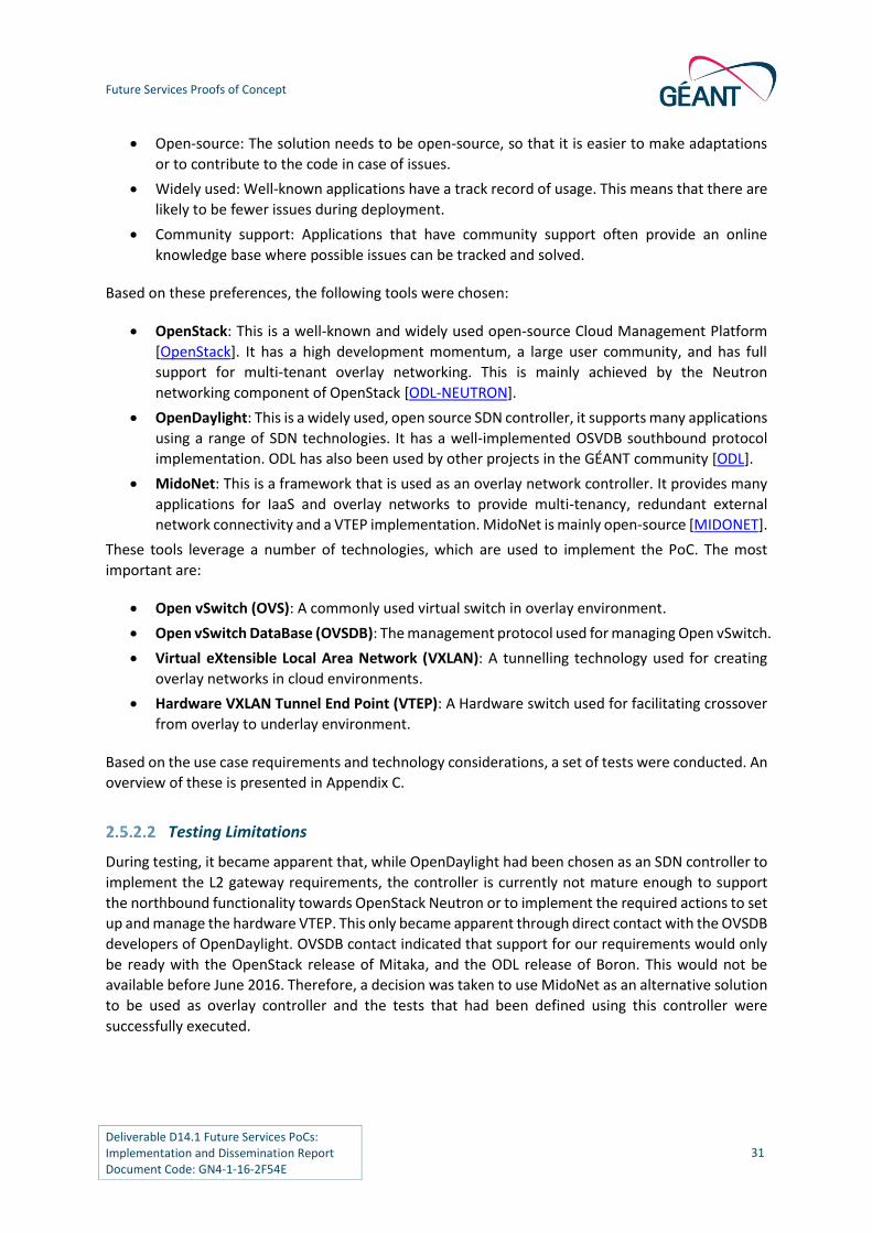
Open-source: The solution needs to be open-source, so that it is easier to make adaptations
or to contribute to the code in case of issues.
Widely used: Well-known applications have a track record of usage. This means that there are
likely to be fewer issues during deployment.
Community support: Applications that have community support often provide an online
knowledge base where possible issues can be tracked and solved.
Based on these preferences, the following tools were chosen:
OpenStack: This is a well-known and widely used open-source Cloud Management Platform
[OpenStack]. It has a high development momentum, a large user community, and has full
support for multi-tenant overlay networking. This is mainly achieved by the Neutron
networking component of OpenStack [ODL-NEUTRON].
OpenDaylight: This is a widely used, open source SDN controller, it supports many applications
using a range of SDN technologies. It has a well-implemented OSVDB southbound protocol
implementation. ODL has also been used by other projects in the GÉANT community [ODL].
MidoNet: This is a framework that is used as an overlay network controller. It provides many
applications for IaaS and overlay networks to provide multi-tenancy, redundant external
network connectivity and a VTEP implementation. MidoNet is mainly open-source [MIDONET].
These tools leverage a number of technologies, which are used to implement the PoC. The most
important are:
Open vSwitch (OVS): A commonly used virtual switch in overlay environment.
Open vSwitch DataBase (OVSDB): The management protocol used for managing Open vSwitch.
Virtual eXtensible Local Area Network (VXLAN): A tunnelling technology used for creating
overlay networks in cloud environments.
Hardware VXLAN Tunnel End Point (VTEP): A Hardware switch used for facilitating crossover
from overlay to underlay environment.
Based on the use case requirements and technology considerations, a set of tests were conducted. An
overview of these is presented in Appendix C.
Testing Limitations
During testing, it became apparent that, while OpenDaylight had been chosen as an SDN controller to
implement the L2 gateway requirements, the controller is currently not mature enough to support
the northbound functionality towards OpenStack Neutron or to implement the required actions to set
up and manage the hardware VTEP. This only became apparent through direct contact with the OVSDB
developers of OpenDaylight. OVSDB contact indicated that support for our requirements would only
be ready with the OpenStack release of Mitaka, and the ODL release of Boron. This would not be
available before June 2016. Therefore, a decision was taken to use MidoNet as an alternative solution
to be used as overlay controller and the tests that had been defined using this controller were
successfully executed.

Future Services Proofs of Concept
Deliverable D14.1 Future Services PoCs: Implementation and Dissemination Report Document Code: GN4-1-16-2F54E
32
2.5.3 Proof of Concept Scenario
The lab presented in Appendix B.2 has been set up and used for the purposes of the PoC. The PoC
entails connecting SURFsara internal L2 networks to the OpenStack overlay environment as tenant
networks, and automatically provisioning the L2-gateway.
Using a hardware VTEP as a L2-gateway, tenant networks existing in the overlay network can be
extended to a layer 2 environment (bridging the cloud to legacy L2). A hardware VTEP could also be
used to extend the Layer 2 environment to overlay networks (bringing legacy L2 to the cloud), or to
extend an L2 light path to a tenant network for the provision of external connectivity.
A vendor-independent approach was adopted to implement and automate the L2 gateway. A switch
based on the Cumulus operating system or Pica8 switches were deemed to be the most appropriate.
Both switches can be managed by OVSDB, since they are actually a Linux server running on a switching
chassis, which can be controlled through the MidoNet overlay controller.
This is a more favourable approach for building a L2 gateway, compared to other hardware vendors
(e.g. Juniper/Arista), as the latter would impose an additional southbound protocol (e.g. NETCONF).
In this way, the L2-gateway can be managed by the same network controller as used for the overlay
network.
Part of the PoC introduces an integrated interface that can manage overlay networks, virtual instances
and L2 gateways. The interface is included in the MidoNet controller package.
Possible Network Technologies Involved in the Scenarios
Neutron L2-Gateway Service Plugin
Recently, a service plugin for managing a L2-gateway through Neutron, was announced at the
OpenStack summit in Vancouver [OSVAN]. The plugin was introduced in the Kilo distribution of
OpenStack [OSKILO].
The plugin allows to easily provision VXLAN tunnels between software VTEPs (Neutron) and hardware
VTEPs (Arista). When the tunnels are created, one can add a mapping from tenant networks in the
OpenStack environment to legacy VLANs connected on physical Arista switches. In this way, traffic can
be bridged between overlay and physical networks. The plugin was tested on Arista 7050X, 7150, 7280
and HP ToR switches. However, it should support any switch that supports the OVSDB hardware_vtep
schema.
The solution is well documented and multiple resources can be found how to set this up, mainly using
Arista and HP switches.
Neutron and OpenDaylight
OpenDaylight is a well-known SDN controller, which also provides support for OpenStack through the
OVSDB southbound protocol.
The OpenStack Neutron integration with OpenDaylight consists of the ML2 MechanismDriver which
acts as a REST proxy and passes all Neutron API calls into OpenDaylight. OpenDaylight contains a
northbound REST service (called the NeutronAPIService) which caches data from these proxy-ed API

Future Services Proofs of Concept
Deliverable D14.1 Future Services PoCs: Implementation and Dissemination Report Document Code: GN4-1-16-2F54E
33
calls and makes it available to other services inside of OpenDaylight. One current user of the
southbound side of the NeutronAPIService is the OVSDB code in OpenDaylight. OVSDB uses the
neutron information to isolate tenant networks using GRE or VXLAN tunnels.
Neutron and MidoNet
MidoNet is an open source overlay controller, with significant support for OpenStack and hardware
VTEP. It uses an agent, which replaces Open vSwitch on the Hypervisor. It is called Midolman agent
and runs on API, gateway, and compute nodes [MIDOLMAN]. It creates a logical network topology on
top of the physical one, using VXLAN (or GRE) encapsulation. The network state is distributed in the
Network State DataBase (NSDB) and stored mostly in Zookeeper and Cassandra.
Last year MidoNet was released as open source. There is a Community Edition, and an Enterprise
Edition with paid support.
MidoNet is well documented on the Internet. There is information available for hardware VTEP
implementations for multiple vendors, including Pica8 and Cumulus.
Based on the aforementioned technologies, Table 2.2 presents an ML2 plugin comparison:
Neutron L2-Gateway Service Plugin
Neutron and OpenDaylight
Neutron and MidoNet
Supported tenant network types
VXLAN VXLAN, GRE
Southbound protocol OVSDB
Used ML2 mechanism_driver
Open vSwitch (service plugin: networking-l2gw)
OpenDaylight No ML2 mechanism driver, MidoNet has its own Neutron plugin
Minimum required OpenStack version
Kilo Mitaka (not released yet) Kilo
Supported Hardware VTEP vendors
Arista, HP, others (not tested)
Any OVS based platform supporting the hardware_vtep schema
Any OVS based platform supporting the hardware_vtep schema
OpenDaylight required? No Yes, ODL beryllium (only full support in Boron)
No
Pros Vendor independent
No additional controller required
Vendor independent
Very flexible
Support for non OpenStack overlay topologies
Vendor independent
Solution well documented
Easy setup (compared to ODL)

Future Services Proofs of Concept
Deliverable D14.1 Future Services PoCs: Implementation and Dissemination Report Document Code: GN4-1-16-2F54E
34
Neutron L2-Gateway Service Plugin
Neutron and OpenDaylight
Neutron and MidoNet
Cons Limited automation options
Overlay topology limited to OpenStack
Complex to set up
development support required for automation process
Cannot function as a SDN OpenFlow controller to support non overlay networking scenarios
Non-OVS based network agent
Table 2.2: ML2 plugin technology comparison
2.5.4 Proof of Concept in SURFsara Lab
A PoC of the use case was deployed on the SURFsara Lab, as a data centre environment with relevant requirements. The network topology of the PoC scenario is as follows:
Figure 2.19: INaaS PoC network topology

Future Services Proofs of Concept
Deliverable D14.1 Future Services PoCs: Implementation and Dissemination Report Document Code: GN4-1-16-2F54E
35
Components in the Scenario
OpenStack controller node
Manages the OpenStack cluster, provides a dashboard to instantiate compute instances, manage hard
drive space, and network components.
OpenStack Compute nodes
These servers host virtual machines which are provisioned and managed through the control node.
OpenStack Network node running SDN controller + Neutron
The network node hosts the OpenStack Neutron application. Manages all network-related items in
OpenStack, such as switching, routing, management of provider/tenant networks, etc. Neutron can
be extended with additional plugins using the ML2 framework, to provide support for third-party
hardware and software. In this case the network node and controller node are integrated on the same
machine.
Hardware VTEP
This is a switch performing the translation between VXLAN and legacy L2 networks. This can be either
a Pica8 or a Cumulus switch. It is used to extend a tenant network towards a physical L2 network.
SDN Controller
The SDN controller (such as MidoNet or OpenDaylight) sits in between Neutron and the VTEP. It acts
as a proxy for Neutron, by means of executing neutron commands using a northbound protocol. It
also manages the VTEP using an OVSDB southbound protocol.
User Story / Flowchart
1. The client wants to launch a VM and connect his/her own network to the VM.
2. Initially the external network needs to be created.
3. Client logs in to the Horizon dashboard.
4. Client creates new network, and fills in all required network name, subnet, and other fields.
5. MidoNet Neutron plugin takes care of L2 provisioning on Cumulus or Pica8 switch.
6. This user story assumes the external network is already configured in Neutron, and MidoNet
configured the hardware switch accordingly using OVSDB.
7. Client Logs in Horizon dashboard.
8. Client start Launch new instance wizard.
9. Client selects his own network from the network tab, fills in other normally required
parameters and boots the VM.
10. In case no DHCP server is available, the client logs into the VM through a console to configure
IP.
11. Client connects to newly launched VM using SSH, to test the connectivity.

Future Services Proofs of Concept
Deliverable D14.1 Future Services PoCs: Implementation and Dissemination Report Document Code: GN4-1-16-2F54E
36
2.5.5 Findings and Conclusions
Multiple approaches for managing overlay networks and hardware VTEPs were tested. The main
conclusion is that the technology is not yet sufficiently mature. For instance, at the time of writing
(April 2016), it is not possible to implement the envisaged scenario using OpenDaylight, as was initially
anticipated. The required driver is still not released, which makes it impossible to manage a VTEP using
ODL. User and design documentation for certain features is often also limited. The alternative
approach using MidoNet has been more successful. This included participating in an evaluation test
where direct support was provided by engineers from Midokura. This allowed for a fast deployment
to carry out the required testing. Much better documentation also proved itself.
In addition, the hardware VTEP implementation on the switches varies by vendor, and introduces a
number of issues. For instance, Juniper switches will only communicate using the OVSDB protocols
through TLS/SSL, which is not supported on many of the SDN controllers. The hardware VTEP
implementation on tested Cumulus OS based switches introduced some issues, mainly based on
availability of the management of the VTEP. The required processes on the switch and on MidoNet
had to be restarted from time to time to ensure proper functionality.
There are many options to provide greater flexibility and automation in the area of overlay networking
and IaaS environments. Most of the testing in the area of managing overlay network topologies has
been successful, and there is much momentum in the development of the used SDN controllers.
2.6 Network in the Campus Proof of Concept
2.6.1 Problem Statement and Objective
Some of the GN4-1 NRENs’ users (labs, researchers, etc.) within universities are requesting enhanced
networking service provisioning, with easier and more time-efficient provisioning mechanisms.
Currently, such requirements are handled by campus NOCs (Network Operations Centres), requiring
considerable amounts of manpower investment, special treatment and manual configuration. The
process of receiving such enhanced services usually involves a great deal of administrative and human
interaction, which is further increased in most of the cases where the upstream NREN is involved in
order to leave the campus.
It would be desirable to have the means to obtain differentiated network services on demand and
through fast and simple allocation mechanisms, which should also be available to any user (usually
researchers) in the campus. In addition, it should be also taken into account that some users may
request non-standard connectivity services that differentiate from the TCP/IP paradigm and thus, they
cannot coexist with it. One of these non-standard connectivity cases are SDN-enabled labs, which are
already being deployed in many campuses. In a number of cases, these SDN labs need to extend their
points of presence over the campus, and require the transparent transport of their communications
traffic over the production infrastructure. In many cases, these labs federate with other labs, which
involve the upstream NREN in delivering non-IP, special purpose connectivity.
The goal of the NitC use case is to use SDN to enable extending special purpose connectivity services
from the upstream network into the campus network, specifically to the end user. Differentiating from
other approaches such as Science DMZ [SCIENCE-DMZ], the approach presented here does not require
the use of dedicated systems for specialized data/flow handling within the campus. It focuses less-
intrusive options.

Future Services Proofs of Concept
Deliverable D14.1 Future Services PoCs: Implementation and Dissemination Report Document Code: GN4-1-16-2F54E
37
There are two actors involved in the NitC use case.
The researcher (user): The person that consumes enhanced network services and/by
performing experiments with it. The researcher desires a way to reserve the resources in
isolation.
The NOC: The Networks Operations Centre of the campus. It manages the network by
monitoring, operating and troubleshooting the university’s network infrastructure.
NOC admins are reluctant to change hardware that is still operational, especially those with paid
maintenance contracts. The separation of the production/standard traffic from the
research/enhanced traffic needs to be done easily, using the actual equipment and available
technologies. The possibility of running parallel SDN and legacy equipment is a realistic possibility for
campuses in a mid-term time frame, and probably will occur since a massive, at-once replacement of
existing hardware is not foreseen.
A potential researcher/user could be someone requesting for a BoD service to access a real time
streaming resource which cannot be recovered afterwards. Another example that could fit into this
use case is the Large Hadron Collider (LHC), which produces very large amounts of data that cannot
be processed in a single place, and so must be disseminated to multiple processing centres. In such a
case, it is clear that the bandwidth needs to be maintained to avoid data loss. Within campuses,
network labs do usually try to break with actual network architectures introducing new terms such as
SDN, Internet of Things (IoT) or Future Internet, among others, that would not interfere with the
production network but that are also unable to run in parallel to it.
Figure 2.20: A hybrid campus infrastructure composed of a legacy and SDN-enabled segments

Future Services Proofs of Concept
Deliverable D14.1 Future Services PoCs: Implementation and Dissemination Report Document Code: GN4-1-16-2F54E
38
As shown in Figure 2.20, specialised traffic handling requirements (light green circles to the right, the
‘SDN side’) co-exist in campus environments together with BoD-related requirements (blue shape to
the left, the ‘legacy side’), the latter being addressed utilising enhancements over the NOC's already
provided services.
Traffic in the SDN side of Figure 2.20 could be TCP/IP agnostic on demand, this means that no firewall,
Network Address Translation (NAT), tunnel or any other mechanism designed to control or shape user
behaviour can be in the path. This traffic should be also possible to identify and deliver or receive from
other universities or research centres via the upstream NREN. The requirements are often similar to
those of Science DMZ (Demilitarized Zone), however, the approach is more dynamic, without the
restriction of being applied on the border of the campus network. A single SDN controller is introduced
to enable the required functionality and expose a single point of entry for users to declare their NitC
requests. Specialised flow handling can be introduced to segments of the campus network; these
segments should also be shared among concurrent users through management policies and
restrictions.
A detailed listing of the requirements emerging from the use case is presented in [JRA2NITC].
2.6.2 Considerations, Limitations and Implementation of Requirements
L2 Connectivity
The NitC use case requires the creation of logical networks on demand based on legacy and SDN
devices. In order to achieve proper Layer 2 connectivity, the handling of special cases such as Layer 2
broadcasts (ARP) must also be taken into account. This is handled seamlessly in the legacy side using
VLANs to create separate broadcast domains, whereas in the SDN side we rely on flow rules instructing
an OpenFlow device to direct a packet out of multiple egress ports. Complications arise when there
are one or more hosts on the legacy side and two or more hosts on the SDN side (and specifically when
at least one of the SDN hosts is on the EdgeBorder switch). Essentially, a broadcast packet originating
from the SDN side must be handled differently based on the egress port; packets sent to the legacy
trunk port need the appropriate VLAN tag pushed, without sending tagged packets to SDN hosts.
Broadcasts arriving from the legacy side normally should not cause such problems, because we only
need to strip the header and forward to SDN hosts. However, it seems that the mechanism used to
perform multicast/broadcast (ONOS single-multi-intent) does not support the pop VLAN actions as
expected.
The following workaround is proposed to resolve that problem:
Switches supporting OpenFlow version 1.3 [ONFSPECv1.3], offer a multi-table pipeline processing.
Hence, the packet can be forwarded in all the SDN hosts, and later, using another pipeline table, the
appropriate tag will be pushed in order to reach the legacy side. In recent versions of OpenFlow
(version 1.5 [ONFSPECv1.5]), the multi-table pipeline can be split between ingress and egress flow
tables. Egress flow tables may process a packet after the output port is specified by an ingress flow
table, thus allowing us to push VLANs based on a packet’s egress port.
In order to account for devices running older versions of OpenFlow, a dedicated switch as the edge
SDN switch is considered. The switch must not have any hosts connected to it, so that VLANs can be
pushed/popped, without having to worry about SDN hosts receiving tagged packets.

Future Services Proofs of Concept
Deliverable D14.1 Future Services PoCs: Implementation and Dissemination Report Document Code: GN4-1-16-2F54E
39
An entire switch is dedicated to act as an edge device and as an alternative, a loop mechanism is placed
in the switch. Two ports (A, B), instead of the entire switch, are then dedicated to act as a bridge. Ports
A and B, are cabled with each other so traffic sent out through A will enter B, which allows handling
of L2 broadcasts by multicasting to every SDN host port, plus to port A. Then a separate flow rule
pushes a VLAN tag to packets arriving in port B (after being outputted from A) and forwards them to
the legacy side.
After setting up logical isolated networks it is important to ensure sufficient network resources. This
can be achieved by rate limiting/guaranteeing bandwidth on specific ports. A rate-limiting scheme4
was tested without success, therefore, further investigations are required. Ideally, we would like to
shape the traffic based on the logical networks (VLANs), although in a way access ports represent only
one VLAN.
NETCONF/ONOS Imitations and Remedies
A requirement imposed by the use case on the legacy side is that the devices have to support
NETCONF. The team experimented with three different Cisco devices:
ISR (Integrated Service Router) 2911
Catalyst switch 2960-S
SM-X-ES3-24-P5 (Switching Module for the ISR)
Configuring/enabling NETCONF is the first step. The desired actions also needed to be formulated in
XML messages. These XML messages are used to perform various RPC (Remote Procedure Call)
operations, and must conform to the NETCONF schema supported by each device.
Such operations are: <get>, <get-config>, <edit-config>, <close-session>. NETCONF offers the
functionality of exchanging RPC operations. It is up to the client (or in our case the SDN controller,
ONOS) to properly formulate a message or modify a template, and then sent an XML to the device.
The CLI commands offered by the router/switch software are the upper bound of what can be done
with NETCONF, and cannot be replaced entirely. During experimentation it was not possible to create
new VLANs/add new descriptions to them, retrieve different types of information in XML format (i.e.
<show> operations for: interface/port status, mac address-table, vlan). Generally, operations
involving the modification of configuration files can be performed using NETCONF. However it is
important to note that neither the structure of a configuration file nor that of the XML Device
Configuration message is vendor agnostic.
The following functionalities were successfully achieved with NETCONF:
Retrieving switch data:
○ Running configuration (RPC <get-config>, equivalent to show running-configuration
command) in XML format.
4 Policy Map each-port-limit Class class-default police 1000000 125000 exceed-action drop # The snippet above should limit the traffic on 1 mbps. 5 Cisco IOS Software, C3560E Software (C3560E-UNIVERSALK9-M), Version 15.0(2)EJ, RELEASE SOFTWARE (fc1).

Future Services Proofs of Concept
Deliverable D14.1 Future Services PoCs: Implementation and Dissemination Report Document Code: GN4-1-16-2F54E
40
○ Performing other show operations in plain text, not XML format (i.e. show mac-address
table, show interfaces, show vlan).
Configuring a switch port as Access/Trunk.
Removing the configuration on a switch port.
NETCONF protocol is supported by ONOS as part of its southbound interfaces set. However, currently
the controller only provides some basic functionality for the implementation of the initiation and
establishment of a NETCONF session towards a given device.
In order to support a particular NETCONF operation towards a given device, the following features are
necessary within ONOS:
This operation should be included in the behaviours API exposed by ONOS core for the
operations on devices.
A driver implemented for this specific device type should implement this behaviour.
Since NETCONF support in ONOS is in its early stages, not all of the desired operations are included in
the ONOS core API. Moreover, the implementation of drivers only includes a limited set of devices,
most notably, no driver for CISCO IOS devices was included in ONOS and should be implemented from
scratch.
The operations required by ONOS core that had to be implemented in the context of the NitC use-
case PoC are the following:
Behaviour interface for directly sending NETCONF XML to a specific device.
Behaviour interface for administering VLANs and trunk mode on device ports.
As previously mentioned, a Cisco IOS driver had to be introduced in ONOS southbound in order to
implement the above behaviours for this specific type of device.
A notable limitation concerns the behaviour for port discovery which is not supported for CISCO IOS.
Port discovery takes place after the device discovery and NETCONF session setup. During this
operation, ONOS interrogates the devices about their ports. In the case of CISCO IOS devices,
NETCONF implementation on devices is not able to provide a reply structured in XML format and
therefore parsing of the reply is not possible within ONOS. The consequence of this limitation is that
the device ports are not available in ONOS core and thus no further manipulation can be performed
on these ports (e.g., they are not visible in the ONOS GUI or cannot be auto-completed/cross-checked
in ONOS CLI commands).
Apart from above features, three new CLI commands where introduced in ONOS to make use of the
introduced behaviours previously mentioned, namely:
Device-setconfiguration: For the sending of raw NETCONF XML messages to a given device.
Device-add-interface: For the configuration of an interface on a device, i.e., addition to a VLAN
and setting to trunk mode.
Device-remove-interface: For the removal of the configuration from a device interface.

Future Services Proofs of Concept
Deliverable D14.1 Future Services PoCs: Implementation and Dissemination Report Document Code: GN4-1-16-2F54E
41
All of the above features have been approved by ON.Lab and are already included into ONOS code-
base, release 1.5 [ONOS1.5].
Dynamic Human Friendly Resource Mapping
One of the challenges to be faced in this PoC was to provide the user with a human-friendly way to
identify the resources that are available for the user. An application to store the relation between the
real resource and its description has been developed. This application uses the ONOS
persistenceService to store the data so that can be easily accessible.
The term “human friendly” is widely used but many times is not defined. In this case, a geographical
meaning for network devices is proposed. A user might not have any kind of technical knowledge and
thus, terms such as ‘switch’ should be avoided. However, a user knows exactly where his/her end-
station/lab is located, the building, the floor, and can easily locate the wall port where the cable is
plugged. Taking this information into account it is possible to provide a location-based structure and
a rough description. The idea is that the description can be as long/short or descriptive as needed,
e.g., ”Wall port below window in Bob’s office with tag #36”. This system also has to work the other
way around. Once a port is selected for provision, it needs to be translated from its human friendly
identifier to a machine-understandable one, such as dpid:port for SDN or ip:port networkport for
NETCONF.
It is important to emphasise that this topological way of representing the information is also very
handy when assigning privileges for the users. Even more levels could be designed and dynamically
created, although this is outside of the scope for this PoC.
Overlay Technologies
Overlay networks were introduced to overcome the limitations of traditional technologies in modern
datacentres. Multi-tenancy and the need for isolation between the tenants was severely diminished
by the limited number of VLANs in a physical network. As a consequence, technologies were designed
to implement virtual networks on top of existing IP networks. Examples of such technologies are STT,
VXLAN, and GENEVE [STT], [VXLAN], [GENEVE]. In general, the aforementioned operate in unison by
encapsulating traffic at the source and de-capsulating at the destination. In other words: by
establishing tunnels that provide Layer 2 connectivity between the tunnel termination points.
Despite the emerging overlay technologies, for the purposes of the PoC, the JRA2 team adopted and
tested the IEEE 802.1q protocol [802.1q] as an overlay technology (VLANs over an Ethernet network),
as it is most widely accepted in legacy environments and is supported by all vendors. Furthermore,
network administrators in campuses are more familiar with this type of technology and for this reason,
more willing to adopt it as an overlay technology.
The main drawback of the 802.1q overlay technology is the restricted number of supported VLANs to
4096. This can be alleviated by alternative approaches such as the QinQ approach which is
standardized by IEEE at 802.1ad. Adopting this approach, it is possible to increase the number of
supported VLANs quite significantly i.e. from 4096 to 4096×4096=16777216. Thus in this way, greater
networking needs can be accommodated and served.
All the above aspects and implementation choices have emerged as an evolution of the initially
defined requirements and the results of the initial testing. The following section describes the
integrated view of all NitC components and capabilities.

Future Services Proofs of Concept
Deliverable D14.1 Future Services PoCs: Implementation and Dissemination Report Document Code: GN4-1-16-2F54E
42
2.6.3 Proof of Concept Scenario
The PoC scenario (implemented in the GÉANT Lab, see Section B.1, also Figure 2.21) consists of an SDN
side with two PICA8 P3922 devices (with one host connected to each one) and a legacy side with two
Cisco SM-X-ES3-24P (again with one host connected to each one). Both sides are connected through
a Gigabit connection.
The PoC is managed with three ONOS applications providing an ONOS integrated UI. The user (NOC or
researcher) interacts with the system only through this interface. The GN4Auth application is in charge
of providing authentication and authorisation services to the PoC. GN4Storage application is in charge
of storing the resources in a human friendly way and organising the information. The GN4NetICUI
application allows the definition of the overlays by the user and enforces the changes into the network.
The SDN side is managed using ONOS intents. The intent service enforces the flows into the devices
through the OpenFlow module. The pair dpid:port is used to define the connectivity. The legacy side
is managed using the NETCONF module of ONOS. Connectivity in the legacy side is defined using VLANs.
Therefore, there is a translation from VLAN to dpid:port mechanism. Unfortunately, it is not possible
at this stage to direct traffic based on VLAN and dpid:port and untag the messages at the same time,
so the only limitation for the user is to use the MAC addresses of the hosts in the legacy side.
Figure 2.21: NitC PoC scenario
The actual configuration of the PoC in the GÉANT Lab is shown in Figure 2.22. The MX devices visible
in the datapath have been used to reduce the 10G ports of Pica8s to 1G ports of the Cisco switches.

Future Services Proofs of Concept
Deliverable D14.1 Future Services PoCs: Implementation and Dissemination Report Document Code: GN4-1-16-2F54E
43
Figure 2.22: Detailed wiring view of NitC PoC scenario
This PoC shows how the NOC manages users (creation/removal/…) that are afterwards assigned to
profiles, which can be trusted with some capabilities that will allow the profile to perform certain
actions. The provisioning part is also taken into account by allowing the registration of resources that
will be related with the geographical position in the campus (building, floor and wallport), so that the
final user is provided with a meaningful description of the resources while operating the system.
Finally, the user’s point of view is demonstrated by allowing the user to create network overlays and
assign ports to the overlays in an intuitive way.
2.6.4 Proof of Concept Set-up
The components of the PoC are:
ONOS: The SDN controller that allows to control an OpenFlow domain. It provides a set of basic
services and features that applications can use. Within this use case work has been done to
extend NETCONF functionality in ONOS.
GN4Auth: App running in ONOS providing with users and profile capabilities.
GN4StorageService: App running in ONOS that stores the relation between network devices
and human friendly descriptions related to where they provide functionality, i.e.: dpid:port is
mapped to building, floor, wallport.

Future Services Proofs of Concept
Deliverable D14.1 Future Services PoCs: Implementation and Dissemination Report Document Code: GN4-1-16-2F54E
44
GN4NetICUI: App that takes information from GN4Auth and GN4StorageService to allow users
to deploy services by themselves when enough permissions are granted by NOC.
PoC workflow
Step 1:
○ The NOC login in the GN4Auth application.
— The NOC user is the only one created upon installation and that cannot/should not be
removed, as well as the ADMIN profile.
Step 2:
○ The NOC creates the buildings, floors and ports within GN4StorageService app.
— The relation between geographical position of the resources and the resources
themselves are stored in a distributed storage service within ONOS that would allow
multiple instances of ONOS access the same information.
Step 3:
○ The NOC creates a profile for Layer 2 users in GN4Auth.
— Profiles are the grouping mechanism that will finally be assigned with the capabilities.
Step 4:
○ The NOC assigns wallport capabilities, MAC address selection and in campus circuit
creation capabilities to the Profile for Layer 2 users.
— Capabilities are not configurable, they depend completely in implementation and
what is embedded in but can be assigned to different profiles dynamically.
○ The NOC creates a User.
Step 6:
○ The NOC assigns the user with the Layer 2 profile.
Step 7:
○ The NOC authorises the user to utilise specific ports.
— The NOC is presented with a list of the provisioned ports. At this stage, the NOC can
allow the user with a specific port, a whole floor or the whole building.
Step 8:
○ The User logs into the system and gets into the NetICUI App.
Step 9:
○ The user creates a Layer 2 Network.
— At this point a VLAN id is assigned for the network. Each Layer 2 network is assigned
with a VLAN id upon creation.
Step 10:
○ The user adds one of the ports that were allowed by NOC to the Layer 2 Network.
Step 11:
○ The user adds more ports to the network.
Step 12:
○ The user sets MAC addresses for ports in the legacy side.

Future Services Proofs of Concept
Deliverable D14.1 Future Services PoCs: Implementation and Dissemination Report Document Code: GN4-1-16-2F54E
45
— This is a restriction due to the inability to use multi-table on the SDN side. This
restriction could be removed if multi-table is used or using multiple links between the
legacy and the SDN side.
Step 13:
○ The user clicks the Apply button and connectivity is provided.
— At this point, the intents are created for the SDN side, and NETCONF commands are
sent to the devices to create the VLANs. Also the edge port in the legacy side is set to
trunk mode.
NETCONF Interaction
Figure 2.23 depicts the messages exchanged in a typical configuration scenario.
In order to connect a device with ONOS, both counterparts exchange NETCONF <hello> messages with
which they announce the supported capabilities (schemas). After the negotiation phase is complete,
ONOS can sent XML messages to the Cisco device.
Specific interfaces can be configured as trunk or access be sending the appropriate <edit-
config> messages. In case the desired setup is no longer needed other <edit-config> messages
are sent to remove the configuration lines. From here the cycle can be repeated, as long as
there is an active NETCONF session.
If there is no need to interact with the device at all, the NETCONF session may be terminated
with the <close-session> operation.

Future Services Proofs of Concept
Deliverable D14.1 Future Services PoCs: Implementation and Dissemination Report Document Code: GN4-1-16-2F54E
46
Figure 2.23: NETCONF Interaction sequence
Note that, in order to remove the trunk configuration from an interface the process needs to be
broken down into two parts. This detailed interaction is presented in Figure 2.24.
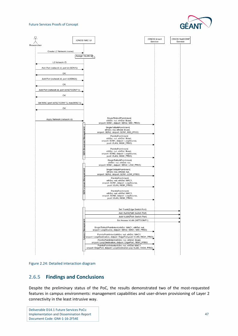
Future Services Proofs of Concept
Deliverable D14.1 Future Services PoCs: Implementation and Dissemination Report Document Code: GN4-1-16-2F54E
47
Figure 2.24: Detailed interaction diagram
2.6.5 Findings and Conclusions
Despite the preliminary status of the PoC, the results demonstrated two of the most-requested
features in campus environments: management capabilities and user-driven provisioning of Layer 2
connectivity in the least intrusive way.

Future Services Proofs of Concept
Deliverable D14.1 Future Services PoCs: Implementation and Dissemination Report Document Code: GN4-1-16-2F54E
48
Although the use case focused on the integration of SDN and legacy hardware, the solution is also
valid for legacy equipment only, which means that each entity can introduce the SDN equipment
progressively, as required.
Bandwidth reservation and guarantees had to be postponed due to the various problems encountered
in interacting with legacy equipment (Cisco IOS) through NETCONF and the amount of effort involved
in developing the needed extensions for the controller.
Regarding NETCONF, although a good choice to integrate other vendors to our system, the integration
of new devices is not straightforward, and some work needs to be done for each specific hardware.
Finally, it is important to emphasise that although using flows instead of intents would provide a more
fine-grained interaction with the devices, the intents present three advantages:
Network errors are transparent for the user and for the NOC.
The NOC can more easily understand what the system is doing.
Assuming NETCONF devices get integrated in the intent framework, no special treatment
would be needed for them, thus simplifying the whole approach.

Deliverable D14.1 Future Services PoCs: Implementation and Dissemination Report Document Code: GN4-1-16-2F54E
49
3 Proof of Concept Key Points
There are a number of key points from the five proof of concept use cases that are important to
reiterate.
In order to bring the SDXL2 and SDXL3 applications to production, some additional concerns
related to security and integration with management systems need to be addressed.
Future work will also include the integration of the missing requirements (for example, the
realisation of a custom route selection process for SDXL3), the development of new services,
such as VPLS, and the continuation of white box switch testing.
The developed SDN-based capabilities can bring considerable savings in the operational costs
and can dramatically reduce the service provisioning time, as they automate many tasks.
Similar improvements in service provisioning and management are also affordable.
Multiple approaches for managing overlay networks and hardware VTEPs were tested. The
main conclusion is that the technology is not yet sufficiently mature.
There are many options to provide greater flexibility and automation in the area of overlay
networking and IaaS environments. Most of the testing in the area of managing overlay
network topologies has been successful, and there is much momentum in the development of
the used SDN controllers.
A robustness test is needed for circuit provisioning and deletion.
Two of the most requested features in campus environments: management capabilities and
user-driven provisioning of Layer 2 connectivity, were addressed by the INaaS PoC in the least
intrusive way.
Although focus has been placed on the integration of SDN and legacy hardware, the solution
is also valid for legacy equipment, which means that each entity can introduce the SDN
equipment progressively, as required.
Although NETCONF has been a good choice for vendor integration, the integration of new
devices is not straightforward and some work needs to be done for each specific hardware.
Although using flows instead of intents would provide a more fine-grained interaction with the
devices, network errors are transparent for the user and for the NOC, the NOC can easily
understand what the system is doing and assuming NETCONF devices are integrated in the
intent framework, no special treatment would be needed thus simplifying the whole approach.
The DynPaC framework could effectively foster the migration to an SDN-based BoD service
provisioning. This framework could be used as the Network Resource Manager (NRM) of
OpenFlow domains, thanks to its compatibility with the NSI-CS protocol. As such, the SDN-
based approach ensures that future BoD deployments can utilise a standards-based
southbound interface (i.e. OpenFlow) to the data plane instead of custom-made technology
specific proxies.
This solution does not only facilitate the integration of OpenFlow domains in the wider, multi-
domain BoD solution, but also enables a future migration to an SDN-based BoD service
provisioning to keep strategic connections with other NRENs.
Future migration to an SDN-based BoD solution will make the BoD service more automated,
flexible and powerful. This solution will benefit GÉANT as a service provider by enhancing

Proof of Concept Key Points
Deliverable D14.1 Future Services PoCs: Implementation and Dissemination Report Document Code: GN4-1-16-2F54E
50
network resource utilisation. It will also benefit current network operators, automating many
of the tasks that are currently done manually. And most importantly, it will benefit end-users
by increasing the service request acceptance ratio and by providing more robust services with
failure recovery guarantees.
Standardisation on the northbound (e.g. controller northbound) interfaces is still an open issue
in the SDN global activities. It is not a significant hurdle in SDN-based services adoption as it is
left to each SDN-enable domain to implement differently. However, standardised east-west
interfaces across SDN enabled domains are very important in a multidomain (i.e. multi-NREN)
environment. NSI can undertake that role as demonstrated by the SDN BoD PoC.
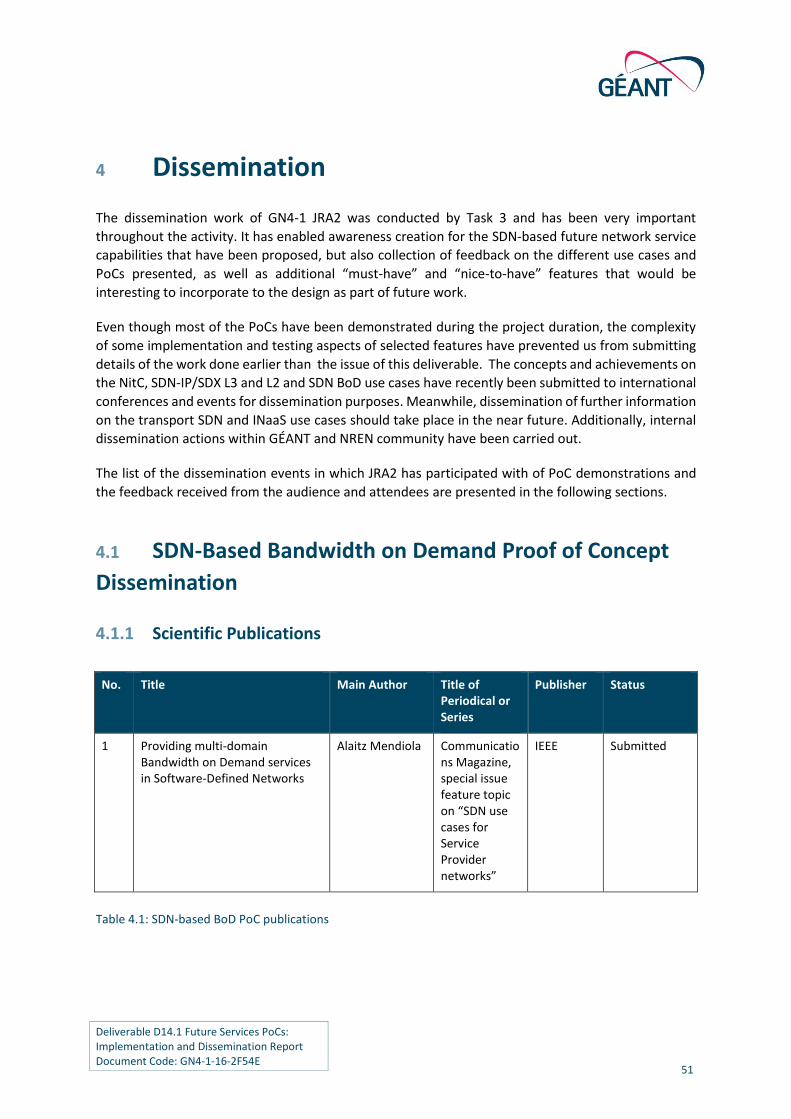
Deliverable D14.1 Future Services PoCs: Implementation and Dissemination Report Document Code: GN4-1-16-2F54E
51
4 Dissemination
The dissemination work of GN4-1 JRA2 was conducted by Task 3 and has been very important
throughout the activity. It has enabled awareness creation for the SDN-based future network service
capabilities that have been proposed, but also collection of feedback on the different use cases and
PoCs presented, as well as additional “must-have” and “nice-to-have” features that would be
interesting to incorporate to the design as part of future work.
Even though most of the PoCs have been demonstrated during the project duration, the complexity
of some implementation and testing aspects of selected features have prevented us from submitting
details of the work done earlier than the issue of this deliverable. The concepts and achievements on
the NitC, SDN-IP/SDX L3 and L2 and SDN BoD use cases have recently been submitted to international
conferences and events for dissemination purposes. Meanwhile, dissemination of further information
on the transport SDN and INaaS use cases should take place in the near future. Additionally, internal
dissemination actions within GÉANT and NREN community have been carried out.
The list of the dissemination events in which JRA2 has participated with of PoC demonstrations and
the feedback received from the audience and attendees are presented in the following sections.
4.1 SDN-Based Bandwidth on Demand Proof of Concept
Dissemination
4.1.1 Scientific Publications
Table 4.1: SDN-based BoD PoC publications
No. Title Main Author Title of Periodical or Series
Publisher Status
1 Providing multi-domain Bandwidth on Demand services in Software-Defined Networks
Alaitz Mendiola Communications Magazine, special issue feature topic on “SDN use cases for Service Provider networks”
IEEE Submitted

Dissemination
Deliverable D14.1 Future Services PoCs: Implementation and Dissemination Report Document Code: GN4-1-16-2F54E
52
4.1.2 Dissemination Events
Table 4.2: SDN-based dissemination events
4.1.3 Received Feedback
For the moment, all the papers submitted have either been accepted or are still under review. In the
case of the accepted proposals, most of the reviewers have agreed that the SDN BoD solution based
on the DynPaC framework could actually be applied to real scenarios in order to solve real problems,
due to the benefits that it can provide to the network operations teams, the end users and the service
providers.
4.2 SDN IP/SDX at Layers 3 & 2 Proof of Concept
Dissemination
With regards the dissemination of the results, top-ranked journals and highly qualified conference
venues in the SDN and NFV research areas have been considered.
No
.
Type
of Activities
Main
Leader
Title Name of Event Date/
Period
Place Type of
Audience
Size of
Audi-ence
Coun-
tries Addressed
Status
1 Workshop
Mian Usman
BoD service plans in GÉANT
LHCOPN-LHCONE meeting
28-29 Oct-15
Amster-dam Nether-lands
Scientific Community (Research)
30 Global Accepted
2 Workshop
Alaitz Mendiola
DynPaC: A Path Computation Framework for SDN
4th European Workshop on SDN - EWSDN
1-3 Oct-15
Bilbao, Spain
Scientific Community (Research)
100 Europe Accepted
3 Symposium
Alaitz Mendiola
Multi-domain Bandwidth on Demand service provisioning using SDN
GN4-1 Symposium
8-9 Mar-16
Vienna, Austria
GÉANT Community
200+ Europe Accepted
4 Conference
Alaitz Mendiola
SDN-enabled AutoBAHN. Envisioning future BoD services
TNC 2016 12-16 June-16
Prague,
Czech Republic
Scientific Community (HE, Research), Industry, Policy Makers, Media, GÉANT Community, EC
700+ Global Planned

Dissemination
Deliverable D14.1 Future Services PoCs: Implementation and Dissemination Report Document Code: GN4-1-16-2F54E
53
4.2.1 Scientific Publications
# Title Main author Journal / Conference Publisher Status
1 SDN-based IP and Layer 2 services with Open Networking Operating System in the GÉANT Service Provider Network
Pier Luigi Ventre
Communication Magazine, special issue feature topic on “SDN use cases for Service Provider networks”
IEEE Submitted
2 Revisiting Open eXchange Points with Software Defined Networking
Pier Luigi Ventre
22nd IEEE International Symposium on Local and Metropolitan Area Networks - LANMAN 2016
IEEE Under preparation at the moment of writing
3 SDN based Open eXchange Point: the prototype of an hybrid OXP in the GÉANT project
Pier Luigi Ventre
2nd IEEE Conference on Network Softwarization - NETSOFT 2016
IEEE Under preparation at the moment of writing
Table 4.3: Publication list
4.2.2 Dissemination Events
# Title Main Leader Event Date Audience Size
of audience
1 GÉANT SDN
Experimentation
- Introducing SDN
capabilities in
backbone
Mian Usman SDN & OpenFlow
World Congress
2015 (SDN+NFV
Innovation track)
12-16 October
2015
Scientific
Community
(Higher
Education,
Research),
Industry,
Civil Society,
Policy
Makers,
Media
1000+ Global
2 DREAMER and
GN4-JRA2 on GTS
Pier Luigi
Ventre
GTS Tech + Futures
Workshop
20 – 22 October
2015
Scientific
Community
50 + remote

Dissemination
Deliverable D14.1 Future Services PoCs: Implementation and Dissemination Report Document Code: GN4-1-16-2F54E
54
# Title Main Leader Event Date Audience Size
of audience
3 SDN in GÉANT
backbone
Mian Usman 7th STF meeting 24–25 February
2016
GÉANT
Access Port
Managers,
Ops
engineers
45 + remote
4 SDN based
Internet
eXchange Point
David
Schmitz
GÉANT Symposium
2016
07–10 March
2016
NREN
community
200
5 Investigating
New Services for
GÉANT Using
Open Networking
Operating System
Matteo
Gerola
Open Network
Summit:
Conference
14–17 March
2016
Scientific
Community
1000 +
remote
6 Global SDN
deployment
powered by
ONOS
Pier Luigi
Ventre
(European
deployment)
Open Network
Summit:
Conference
14–17 March
2016
Scientific
Community
1000 +
remote
Table 4.4: Event list
Feedback received
At time of writing, the GÉANT SDN IP / SDX use case has been presented twice: at the 2015 GTS
workshop and at the Open Networking Summit. Moreover, it has been demonstrated at the Open
Networking summit conference as part of the “Global SDN deployment powered by ONOS” (two
presentations and one showcase).
Several service provider operators found the applications very useful for the agile management of
both Layer 3 and Layer 2 services. The PoCs were found to be very interesting and ambitious for large
scale deployments.
In general, the audience appreciated:
The design of the GÉANT SDX, that allows a smooth transition from the current OXP/PoPs
infrastructure towards more flexible and less expensive points of presence and a seamless
integration with the rest of the GÉANT infrastructure.
The modularity of the architecture, that allows independent start and stop of the Layer 3 and
the Layer 2 services without impact on the infrastructure.
The Realisation of the solution in a short time/limited resource consumption.

Dissemination
Deliverable D14.1 Future Services PoCs: Implementation and Dissemination Report Document Code: GN4-1-16-2F54E
55
However, the audience also expects GÉANT to deploy these services in production to demonstrate
their resiliency and scalability in real deployment and real workloads.
4.3 Transport SDN Proof of Concept Dissemination
4.3.1 Dissemination Events
Table 4.5: Transport SDN PoC dissemination events
4.3.2 Received Feedback
Infinera attended the GÉANT network evolution workshop at the symposium, endorsing the approach
upon which the GÉANT team and Infinera work collaboratively. The feedback from Infinera was that
the R&E community needs to consider the multiple standardisation efforts for Management
information Bases (MIBs). Infinera is making use of the YANG model and recent work coming out of
IETF [YANG]. The key here is to encourage coordination of information model selection so that
interoperation between vendors and network providers is facilitated.
No.
Type of Activities
Main Leader
Title Name of Event
Date/ Period
Place Type of Audience
Size of Audi-ence
Countries Addressed
Status
1 GÉANT meetings
Mian Usman
SDN in GÉANT backbone
7th STF meeting
24-25 February 2016
Amsterdam
GÉANT Access Port Managers, Ops engineers
45+ remote
Europe Accep-ted
2 Sympos-ium
Mian Usman
GÉANT Network evolution
GN4-1 Symposium
8-9 March 2016
Vienna, Austria
GÉANTCom-munity
200+ Europe Accep-ted

Dissemination
Deliverable D14.1 Future Services PoCs: Implementation and Dissemination Report Document Code: GN4-1-16-2F54E
56
4.4 Infrastructure and Network as a Service Proof of
Concept Dissemination
4.4.1 Dissemination Events
Table 4.6: INaaS PoC dissemination events
4.5 Network in the Campus Proof of Concept
Dissemination
4.5.1 Dissemination Events
Table 4.7: NitC PoC dissemination events
No. Type of
Activities
Main
Leader
Title Name of Event Date/
Period
Place Type of
Audience
Size of
Audi-ence
Countries
Addressed
Status
1 Sympos-ium
Erik Ruiter
INaaS Developments Overview
GN4-1 Symposium
8-9 March 2016
Vienna, Austria
GÉANT Community
200+ Europe Accepted
No. Type of Activities
Main Leader
Title Name of Event
Date/ Period
Place Type of Audience Size of Audience
Countries Addressed
Status
1 Demo Session + Poster
Jordi Ortiz
SDN Integration and Manage-ment Solutions for Campus Network Enhanced Services
Innovations in clouds, Internet and Networks - ICIN 2017
02-03--2016
Paris, France
Scientific Community Research
80 Global Accepted
2 Demo Session
Jordi Ortiz
SDN Integration and Manage-ment Solutions for Campus Network Enhanced Services
GN4-1 Symposium
08-03- 2016
Vienna, Austria
GÉANT Com-munity 200+ Europe Accepted
3 Lightning talk
Jordi Ortiz
TNC 2016 12/16-06-2016
Prague, Czech Republic
Scientific Com-munity (HE, Re-search) Industry, Policy Makers, Media, GÉANT Community, EC
700+ Global Planned

Dissemination
Deliverable D14.1 Future Services PoCs: Implementation and Dissemination Report Document Code: GN4-1-16-2F54E
57
4.5.2 Received Feedback
During the PoC dissemination activities, there was great interest on how the proposed enhanced
network services within the campus could be extended with those provided by the NREN and how the
user could provision himself those services when trusted by the NOC. Although neither the poster nor
the demo focused on extra-campus connectivity, the audience was interested to know how such intra-
campus capabilities could be extended.
Regarding VLAN selection as an overlay mechanism, there were questions regarding dropping the
VLAN tag at the SDN side instead of maintaining it to direct traffic to destination. Performance issues
were indicated as a reason, without always being convincing to the audience.
Overall, the audience was pleasantly surprised by the functional PoC.

Deliverable D14.1 Future Services PoCs: Implementation and Dissemination Report Document Code: GN4-1-16-2F54E
58
5 Summary and Next Steps for Future Network Services
Overall, the work on SDN-enabled future network service capabilities during GN4-1 JRA2 has resulted
in:
Significant knowledge development for the GÉANT software and network engineers, as well
as operations teams.
Significant insight on community-supported SDN-controller frameworks.
First-hand assessment of SDN support in legacy and white box hardware.
Collaboration with industry and collaborative developments to deliver SDN capabilities.
Contribution to the core code of ONOS controller with functionality relevant for backbone
service providers and campus providers.
Visibility of GÉANT SDN activities and evolution path.
The next step for the use cases presented in this document is their further development and
deployment in pre-production environments for further validation and testing, with the ultimate goal
being their deployment as service capabilities in operational environments.
Based on the work reported in this document, a number of functional and operational aspects need
to be further developed to lead to stable solutions that can form part of service offerings. A series of
pilots will be required to advance the PoCs to pre-production solutions. The challenges are to work
on the developed SDN applications but also to evolve the maturity of the overall ecosystem, including
the community SDN controllers and vendors’ support of SDN.
The SDN-based BoD use case is considered mature enough to be deployed in pilots early in the process.
Application functionalities to be further developed include fine-grained handling of constraints,
dynamic handling of all types of topology updates and support for VLAN translation. The application's
capability to interoperate with any NSI-compliant domain will also be verified, based on the limited
domain interoperation that was demonstrated via the PoC. Introducing the NitC application to solve
the last mile issue is also anticipated.
SDX Layer 2 capabilities are also quite mature to be deployed in pilots. In this case, identifying the
tunnelling modes (MAC, VLAN or MPLS-based) that are relevant and efficient operationally, and
verifying that they scale to the requirements of GÉANT exchange points will be the main goal.
The functional prototype of the Transport SDN use case will be made available after the end of GN4-
1 and will then have to be deployed in a pilot using the Infinera equipment available in GÉANT. Further
ahead, in conjunction with the SDN-IP application, it will be used to enable multi-layer coordination
through a single SDN controller.
The SDXL3 application will follow, with the primary goal of verifying its scalability against the
requirements set by GÉANT. After ensuring scalability, the SDN-IP/SDXL3 applications will be
Summary and Next Steps for Future Network Services
Deliverable D14.1 Future Services PoCs: Implementation and Dissemination Report Document Code: GN4-1-16-2F54E
59
evaluated in pilots for pre-production deployment, in conjunction with the GÉANT network evolution
planning.
Finally, interconnection of L2 legacy networks to multi-tenant cloud environments will be further
investigated and evaluated as part of integration with e-Infrastructures and cloud providers, as
proposed for future work.

Deliverable D14.1 Future Services PoCs: Implementation and Dissemination Report Document Code: GN4-1-16-2F54E
60
Appendix A Testing of the Requirements: Methodology
In GN4-1 JRA2, a testing strategy was put in place to guide testing as well as the implementation of
the proposed use cases’ Proofs of Concept (PoCs). The testing strategy enabled the team with
technical coherence, categorisation of the tests performed, identification of the required testing
resources and timely/efficient testing execution. A testing plan template was prepared for each of
the proposed use cases. Later, the template was customised to the specifics of the concrete use case
PoCs. The most important aspects of the testing methodology are provided in this Appendix.
A.1 Requirements Traceability Matrix
The traceability matrix enables to track the development, status and execution of the tests. The main
purpose of Requirement Traceability Matrix is to ensure that no functionality is left out of testing and
it is a live document that must be properly updated as the testing progresses. One traceability matrix
per use case was created in the JRA2 wiki space. The different fields of the table are detailed here:
ID: A unique ID number used to identify the traceability item in the requirements traceability
matrix.
Requirement: This column should be populated with a short technical description of the
requirement.
Type of requirement: It can be a general requirement linked to some others, or use case
specific:
○ Use case specific.
○ Generic requirement.
Type of test: To identify the type of test that is intended to be run:
○ Unit/component testing.
○ Integration testing.
○ Performance testing.
○ Stress testing.
Status: This column should be populated with the current status of the functional requirement:
○ Designing,
○ Preparing

Testing of the Requirements: Methodology
Deliverable D14.1 Future Services PoCs: Implementation and Dissemination Report Document Code: GN4-1-16-2F54E
61
○ Execution ongoing.
○ Finalised.
Test plan design document: This column should be populated with a LINK to the test plan
design document (separate document for each of the requirements). It must include:
○ Requirement ID.
○ Approach.
○ Requirement testing tasks.
○ Input: Determine the test entry.
○ Output and describe the exit criteria. (What is the expected outcome/verification mean
once the test has finalized). Pass / Fail criteria.
○ Facilities: Scenario (resources, components, equipment, required software).
○ Procedure.
○ Schedule.
○ Responsible.
○ Observations.
○ Success or Failure Type.
Schedule: You can book here the time slot(s) when each requirement will be tested (high level).
It must match the schedule set in the test plan design document.
Responsible: This column should be populated with the responsible of testing each of the
requirements of the use cases.
Test case number: This column should be populated with the test case number linked to the
requirement.
Success or Fail: Specify is the requirement test passed or failed.
Additional comments:
Figure A.1 shows a screen shoot of a partial view of a traceability matrix for the SDN-based BoD use
case. As it can be shown, the purpose of the traceability matrix is to provide a quick view on the up-
to-date status of each of the requirements to be tested at a glance.

Testing of the Requirements: Methodology
Deliverable D14.1 Future Services PoCs: Implementation and Dissemination Report Document Code: GN4-1-16-2F54E
62
Figure A.1: Screenshot of the SDN-based BoD use case traceability matrix taken in January 2016
A.2 Test Plan
A.2.1 Purpose of the Test Plan
The purpose of the test plan is to guarantee that all the necessary elements to carry out the testing of
the requirements are in place before executing the testing, to identify whether the testing has failed
or succeeded and to enable, with the means to restructure, the testing of a requirement in case the
test failed. The test plan should be understood as a tool to keep the test environment under control
and guide the preparation process in advance of the testing execution. One test plan for each of the
requirements of the use cases was created at the JRA2 wiki space.
A.2.2 Test Strategy and Performance
The test strategy and performance has been planned considering the other involved tasks of the
activity - Task 1 Future Network Services’ requirements and architectures and Task 2 Future Network
Services’ software solutions – to synchronise and align the efforts towards the implementation of the
use cases’ PoCs. Figure A.2 shows the test strategy conceived in Task 3, including the different parts
that compose the testing activity (including: the traceability matrix, the test plan, text execution and
documentation and test analysis and feedback) and the relation to Task 1 and Task 2.

Testing of the Requirements: Methodology
Deliverable D14.1 Future Services PoCs: Implementation and Dissemination Report Document Code: GN4-1-16-2F54E
63
Figure A.2: Detail of the Task 3 test strategy in the context of the overall JRA2 activity
A.2.3 Test Plan Design
The test plan design followed a general approach to enable the preparation of different types of
testing (mainly physical equipment, software and integration testing). Each use case comprises a test
plan per each of their requirements that includes the following items:
Requirement ID: ID of the requirement given for identification purposes.
Requirement name: Name given to the requirement.
Linked to: It may be the case that the requirement is also addressed in other use cases. In case
the testing has already been done, there is no need to repeat it. Indicate the link to the site,
the use case, and requirement ID of the one that has been tested and there is no need to
complete the whole testing process.
Approach: Describe the overall approaches to testing. The approach should be described in
sufficient detail to permit identification of the major testing tasks and estimation of the time
required to do each task. Identify the types of testing to be performed along with the methods
and criteria to be used in performing test activities. Describe the specific methods and
procedures for each type of testing.
Task 1 Task 2 Task 3
Requirements and architecture
SW solutions and implementation
Testing, PoCs & demonstration. Dissemination
Prototype
Disseminate
Traceability matrix (1 per use case)
Req. ID
Pass/Fail criteria
Expected testing output
Test Execution
Test Documentation
Analysis of the testing
Passed/Failed?Test Steps
Test Documentation
Prototype amendment
Software amendment
Reformulate requirement?
Passed
Failed
YESDiscard
requirement
NO
Add to
Implement Test plan
Task 1
Task 2
Task 1 req. to be tested
Requirement ready for PoC
Task 2 req. to be tested

Testing of the Requirements: Methodology
Deliverable D14.1 Future Services PoCs: Implementation and Dissemination Report Document Code: GN4-1-16-2F54E
64
Requirement testing tasks/procedure/steps: Identify the set of tasks necessary to prepare for
and perform testing activities. Identify all inter-task dependencies and any specific skills
required.
Input: Identify the inputs required to trigger each test.
Output and Exit (Pass/Fail criteria): Identify the outputs from each type of testing. What is the
expected outcome/verification mean once the test has finalized. Also specify the criteria to
be used to determine whether each item has passed or failed testing. The test of the
requirement is considered as successful, once the “output” and the “pass criteria” are the
same.
o Approval Criteria: Specify the conditions that need to be met to approve test results.
o Fail Criteria: Specify the conditions that indicate that the test has not been
successfully accomplished.
o Test output: Specify the output of the test.
Facilities: Identify the resources allocated for the performance of testing tasks. Identify the
components, the equipment, the required software, tools, etc.).
Test scenario figure that includes the physical scenario set up with all the involved equipment
and software.
Responsible and participants: Responsible person of executing and documenting the test of
the requirement and other involved participants.
Schedule: Specify the concrete date(s) when the test execution will take place.
Observations: Include any relevant additional considerations.
Success or Failure Type: Choose among one of the following categories: Critical, High, Medium,
Low.
Test plan summary table: The table contains a summary of previous items to prepare the test
of each of the requirements. The summary tables of each of the requirements that have been
tested have been included in the wiki space of each of the UCs. Table A.1 represents an
example of a test plan summary table for a concrete requirement.
Requirement ID: #45
Requirement Name: Change Password – Normal State
Linked to: wiki.geant.org/pages/xxxxx Requirement #33 of use case “BoD”.
Requirement testing
tasks/procedure/
steps
1. Launch software application Login Screen 2. Type in test username and password, click “Login” 3. Click on link for “Settings” 4. Click on link for “Change Password”

Testing of the Requirements: Methodology
Deliverable D14.1 Future Services PoCs: Implementation and Dissemination Report Document Code: GN4-1-16-2F54E
65
5. In pop-up text box, type existing password in “Existing Password” field using numbers, letters and symbols
6. In pop-up text box, type new password in “New Password” field 7. In pop-up text box, type new password in “Confirm New Password”
field 8. Click “Ok” 9. Click “Exit Application” 10. Launch software application Login Screen 11. Type in test username and modified password, click “Login”
Setup/input Introduce username and previous password.
Exit (Pass/Fail criteria) Approval criteria: The password has been successfully changed.
Fail Criteria: The password has not changed
Expected
Output(s)/Result(s):
1. Login Screen appears 2. System accepts login and launches Main Screen 3. Settings screen appears 4. Change Password pop-up text box appears 5. Text box accepts numbers, letters and symbols 6. Text box accepts numbers, letters and symbols 7. Text box accepts numbers, letters and symbols 8. System accepts the password change 9. Application closes 10. Login Screen appears 11. System accepts login and launches Main Screen.
Facilities Detail the required facilities to carry out the testing
Hardware
Software
Other tools, techniques, methodologies, etc.
Test scenario Figure A figure including the testbed performance, equipment, software, etc.
Responsible
and participants Responsible: José Aznar
Participants: José Aznar, John Doe, etc.
Schedule 03/02/2016

Testing of the Requirements: Methodology
Deliverable D14.1 Future Services PoCs: Implementation and Dissemination Report Document Code: GN4-1-16-2F54E
66
Observations No other observations
Success or Failure
Type (Critical, High,
Medium, Low)
Critical
Table A.1: Example of a test plan summary table
A.2.4 Test Execution and Documentation
Once the test of a requirement has been planned and the resources are in place, the test execution
follows. The execution should be executed according to the steps which have been established in the
“procedure” field of previous test plan summary table.
One requirement may need one or more tests. All of them are documented and include a “test case
number” to differentiate among the different tests of the same requirement. Additionally, the test is
validated/rejected by comparing the “Expected Output(s)/Result(s)” specified in the test plan
summary table with real outcomes of the testing.
A.2.5 Analysis of the Testing and Feedback
The analysis of the tested requirement involves two possibilities:
In case the testing has succeeded, the requirement is ready to be part of the functionalities
that will demonstrate the proposed use case in a later stage.
In case the testing failed, the reason why it failed is analysed. During the testing phase, several
reasons for test failure have been identified:
○ In the case of a software implementation test, the implementation does not satisfy the
expected performance.
○ In the case of equipment testing, the equipment does not support some specific features
that are required to match the expected outcome.
○ In the case of an integration testing requirement, the interfaces or connectors among the
resources and or the software managing the resources do not behave as expected.
For each concrete test, a decision on the next steps is taken. In the case of software testing, the
possibility of re-implementing or modifying the functionality is evaluated. For equipment and
integration tests, the possibility of reformulating the testing, or including some alternative equipment
that may satisfy the test is analysed. In case alternative ways to address the requirement have been
identified, then the testing wheel suggests to repeat the cycle. Otherwise, the requirement is marked
as “not achievable” and removed from the list of functionalities.

Testing of the Requirements: Methodology
Deliverable D14.1 Future Services PoCs: Implementation and Dissemination Report Document Code: GN4-1-16-2F54E
67
A.2.6 Testing Methodology Outcomes
As the planning and execution of JRA2 PoC tests progressed, it became apparent that the resulting
methodology challenges should be captured and addressed in a more systematic way for the benefit
of future testing activities, particularly those conducted during the transition to operational use. In
addition, establishing a common understanding of testing work and terminology between JRA and SA
activities would help both, particularly when some technology or solution that was successfully
assessed for possible future application is eventually migrated to the operational infrastructure.
Although the tests conducted within JRAs are more limited in terms of scope and resources than the
highly formal tests required before the launch of actual services, both types of testing would benefit
from a closer alignment of their approaches and documentation.
Inspired by the ongoing work of JRA2, GN4-1 SA4 Task 1 “Quality validation and testing” produced a
Testing Framework as part of SA4 Task 1 public knowledge base. Starting from the live documentation
and specifications of its JRA2 use cases, requirements, test plans, environment descriptions and
execution logs, this document outlined a structured approach to testing, dealing with testing best
practices, management, enactment, documentation and tailoring. It also provides a source of common
terminology. The highlights from this document and its glossary were incorporated into the GN4-1
deliverable D8.1 “Service Validation and Testing Process” [D8.1].
This Testing Framework is aligned with the major standards in the field, such as ISO/IEC/IEEE 29119,
IEEE 829 and BS 7925, complements ITIL recommendations and processes, but is, at the same time, in
line with the common language and practices of testing.
Although it is primarily meant to support the GÉANT validation and testing practices for software-
based services and the related infrastructure (the mentioned standards are primarily related to testing
of software systems), the developed framework was prepared also with hardware and system testing
in mind. It therefore may help in strengthening of the common ground between networking engineers,
software developers, testers and end-users. It can be used to help consolidating evaluation of various
externally developed products and solutions, those developed and by GÉANT community, and even
throughout the service lifecycle - that is, before upgrades or enhancements of GÉANT services.

Deliverable D14.1 Future Services PoCs: Implementation and Dissemination Report Document Code: GN4-1-16-2F54E
68
Appendix B Testbed Facilities
For the purposes of the PoC design and deployment, advanced testbed facilities were implemented.
In this section, a summary of the facilities utilised and developed for the purposes of JRA2 PoCs are
presented.
B.1 GÉANT Lab
The GÉANT Lab in Cambridge was made available for the JRA2 activity to use for the deployment of
SDN equipment and the development, testing and validation of use cases. The presence of a physical
Lab has been a fundamental driver providing a centralised location for use by the whole activity.
Having a centralised environment greatly simplified the coordination of testing activities and the
sharing of information and findings across teams.
The GÉANT Lab provides a large amount of equipment and space. It is also well maintained and
connected, as it is regularly used by the GÉANT Operations team for software and product testing, and
validation. The Lab includes a number of routing, switching and optical transmission nodes as well as
several virtual machines servers.
Figure B.1 below shows the non-SDN part of the Lab. The available equipment in the lab includes:
3 x Juniper MX-480
1 x Juniper MX-960
1 x Juniper M120
4 x Cisco routers
The above equipment is used to emulate the GÉANT production network, which helps with PoC testing.
The topology of the equipment is connected is shown below:

Testbed Facilities
Deliverable D14.1 Future Services PoCs: Implementation and Dissemination Report Document Code: GN4-1-16-2F54E
69
Figure B.1: LAB in Cambridge testbed facilities – non-SDN part
As part of the JRA2 work, a number of hardware SDN switches from different Dell, Pica8 and Corsa
vendors were also deployed to complement the already rich set of equipment and provide a complete
environment for SDN testing.
The SDN-specific part of the Lab is shown in Figure B.2: . Figure B.3: shows the SDN lab topology in
Cambridge, with management IP addresses. It consists of the following equipment:
2 x Corsa 6410 Switches.
2 x PICA 8 Switches.
2 x Dell S4810 Switches running Cumulus Linux.
1 x Dell Server for VMs.
It also connects to the GÉANT Juniper MX lab which is shown in Figure B.3: . The topology can be
changed by shutting down any ports that are not needed.
The SDN-specific part of the Lab is shown in Figure B.2:
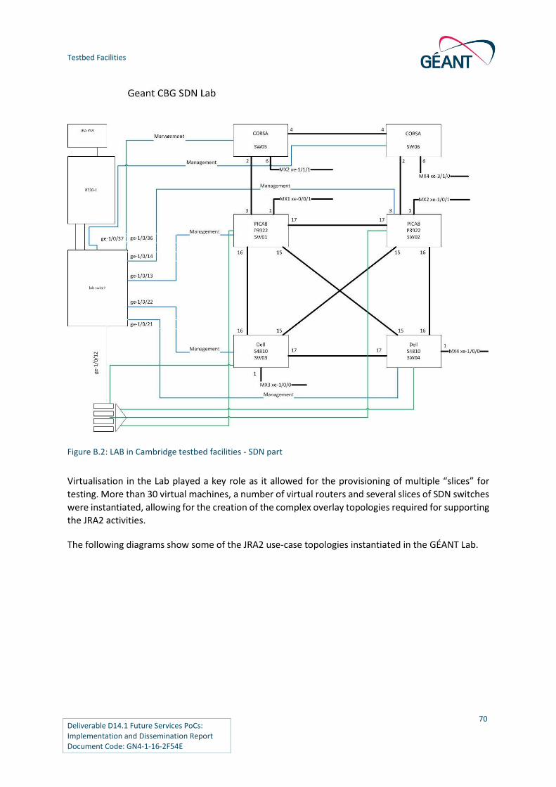
Testbed Facilities
Deliverable D14.1 Future Services PoCs: Implementation and Dissemination Report Document Code: GN4-1-16-2F54E
70
Figure B.2: LAB in Cambridge testbed facilities - SDN part
Virtualisation in the Lab played a key role as it allowed for the provisioning of multiple “slices” for
testing. More than 30 virtual machines, a number of virtual routers and several slices of SDN switches
were instantiated, allowing for the creation of the complex overlay topologies required for supporting
the JRA2 activities.
The following diagrams show some of the JRA2 use-case topologies instantiated in the GÉANT Lab.

Testbed Facilities
Deliverable D14.1 Future Services PoCs: Implementation and Dissemination Report Document Code: GN4-1-16-2F54E
71
B.1.1 GÉANT Lab Setup for the NitC Use Case
Figure B.3: Slice of the GÉANT Lab facilities dedicated to the NitC use case PoC implementation and
demonstration.

Testbed Facilities
Deliverable D14.1 Future Services PoCs: Implementation and Dissemination Report Document Code: GN4-1-16-2F54E
72
B.1.2 GÉANT Lab Setup for the SDN Use Case
Figure B.4: Slice of the GÉANT Lab facilities dedicated to the SDN BoD use case PoC implementation and
demonstration
B.1.3 GÉANT Lab Setup for the SDN IP Use Case
Figure B.5: Slice of the GÉANT Lab facilities dedicated to the SDN use case PoC implementation and
demonstration

Testbed Facilities
Deliverable D14.1 Future Services PoCs: Implementation and Dissemination Report Document Code: GN4-1-16-2F54E
73
Apart from general-purpose SDN equipment and software testing, the Lab was primarily used for
instantiating the PoC demonstrators at various events. Isolation among the PoC deployments was
ensured, to allow for different PoC demos to be run in parallel at the relevant events. All demos were
run live, directly from the GÉANT Lab.
B.2 SURFsara Facilities
SURFsara operates a test lab in Amsterdam that has been devoted to test and validate the INaaS use
case [SURFsara]. This lab hosts a number of physical compute servers and various brands / types of
networking equipment. It runs a Mirantis OpenStack deployment based on Ubuntu 14.04, on three
nodes [MIRANTIS].
This setup has been made available for the INaaS workgroup as part of GN4_JRA2 by means of a
intermediate host stepping stone, which is connected to the firewall connected to the internet, using
a SURFnet link. A number of networks are configured to be able to operate the OpenStack
environment in multi-tenant setup using Neutron and VXLAN tunnelling. This also provides
segmentation between management and production networks.
In addition to the available servers, there is also networking equipment available from various vendors,
including Dell, Juniper and Pica8. This can be used to build networking scenarios to test external
connectivity for the OpenStack cluster.
Figure B.6 shows SURFsara testbed overview:
Figure B.6: SURFsara OpenStack lab topology

Deliverable D14.1 Future Services PoCs: Implementation and Dissemination Report Document Code: GN4-1-16-2F54E
74
Appendix C Summary of Testing Results for the INaaS Use Case
Requirement Type of test Success
or Fail
Additional Comments
OpenDaylight (and / or Neutron) can
identify resources in an OVS
Component
Testing
Success
(with ODL
xSQLsql)
Follow up on relating VM to OVS
interface by REST interface
OpenDaylight (and / or Neutron) can
create new resources in an OVS
a. Create a new virtual port in an OVS
b. Create a VLAN in OVS
Component
Testing
Success
(with ODL
REST)
OpenDaylight (and / or Neutron) can
configure VLANs on ports, access and
trunk
Component
Testing
Success
(with ODL
REST)
Requires Corsa driver activation
OpenDaylight (and / or Neutron) can
present port information such as state,
traffic statistics, VLAN assignment
Component
Testing
Mostly
Success
(with
xSQLsql)
Follow up to check whether the
VLAN assignment can also be
queried with REST calls
OpenDaylight (and / or Neutron) can
configure L2 protocols on OVS ports.
Protocols to be tested LACP and STP
Component
Testing
Current status: Only interface to
query current state of LACP and
STP in ODL
OpenDaylight (and / or Neutron) can
create a virtual port in OVS of VXLAN
type IP address of remote tunnel end
point should be provided as an
argument
Component
Testing
Success

Summary of Testing Results for the INaaS Use Case
Deliverable D14.1 Future Services PoCs: Implementation and Dissemination Report Document Code: GN4-1-16-2F54E
75
Requirement Type of test Success
or Fail
Additional Comments
OpenDaylight (and / or Neutron) can
orchestrate the two servers/nodes in
order to acquire the VXLAN tunnel and
use it as a L2 pipe between desired
running OVS instances
Component
Testing
Success
OpenDaylight (and / or Neutron) can
create a virtual port in OVS of GENEVE
type. IP address of remote tunnel end
point should be provided as an
argument
Component
Testing
– GENEVE is not supported in Lab
OpenDaylight (and / or Neutron) can
orchestrate the two servers/nodes in
order to acquire the GENEVE tunnel
and use it as a L2 pipe between desired
running OVS instances
Component
Testing
– GENEVE is not supported in Lab
Implement network topology in a
single VLAN using Neutron
Attach vmA in ovsA port 1 running in
host A
Configure port 1 on ovsA as access to
vlan RED
Attach vmB in ovsB port 1 running in
host B
Configure port 1 on ovsB as access to
vlan RED
Attach vmC in ovsC port 1 running in
host C
Configure port 1 on ovsC as access to
vlan RED
Component
Testing
Success
Create VXLAN tunnels between hosts
A,B and C. Verify that no loop is created
using Neutron and OpenDaylight
Component
Testing ODL +
Neutron
Success
Create OF rules for learning MACs in
data plane
Component
Testing ODL
– OpenFlow rules are created by
Open vSwitch

Summary of Testing Results for the INaaS Use Case
Deliverable D14.1 Future Services PoCs: Implementation and Dissemination Report Document Code: GN4-1-16-2F54E
76
Requirement Type of test Success
or Fail
Additional Comments
Create OF rules for broadcast traffic
forwarding between the VMs
belonging to broadcast domain RED
Component
Testing ODL
– OpenFlow rules are created by
Open vSwitch
Create OF rules for unicast traffic
forwarding between the VMs
belonging to broadcast domain RED
Component
Testing ODL
– OpenFlow rules are created by
Open vSwitch
Implements / supports an NBI and can
be managed either by ODL/MidoNet or
Neutron. NB protocols should be
OVSDB and/or OF
Component
Testing
MidoNet
Success
Supports VXLAN, be able to operate as
VTEP
Component
Testing
MidoNet
Success Supported by MidoNet / Neutron
using a Cumulus switch as HW
VTEP
The HVXLANGW should be able to
maintain 2 VXtunnel interfaces
towards the 2 compute nodes, and
carry traffic belonging to multiple VNIs
Component
Testing
MidoNet
Success Supported by MidoNet / Neutron
using a Cumulus switch as HW
VTEP
Regarding the VLAN side (or legacy
side) the gateway should behave like a
typical bridge. Combining VXLAN and
VLAN sides the HVXLANGW should
support mapping VNI-to-VLAN, which
should be configurable via the NBI
mentioned in [PEPELNJAK] and mainly
bridge (Only L2) the mapped VNI to
VLAN
Component
Testing
MidoNet
Success Is supported by MidoNet / Neutron
using a Cumulus switch as HW
VTEP
Table C.1: Summary of testing results for the INaaS use case
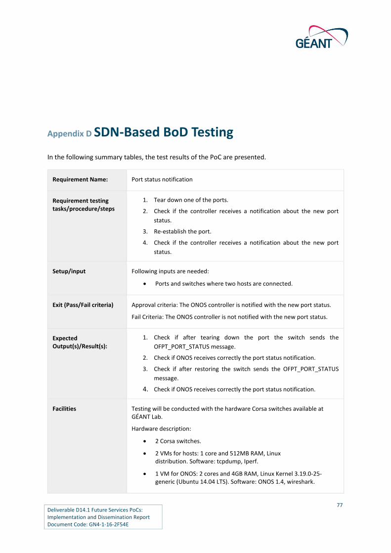
Deliverable D14.1 Future Services PoCs: Implementation and Dissemination Report Document Code: GN4-1-16-2F54E
77
Appendix D SDN-Based BoD Testing
In the following summary tables, the test results of the PoC are presented.
Requirement Name: Port status notification
Requirement testing tasks/procedure/steps
1. Tear down one of the ports.
2. Check if the controller receives a notification about the new port
status.
3. Re-establish the port.
4. Check if the controller receives a notification about the new port
status.
Setup/input Following inputs are needed:
Ports and switches where two hosts are connected.
Exit (Pass/Fail criteria) Approval criteria: The ONOS controller is notified with the new port status.
Fail Criteria: The ONOS controller is not notified with the new port status.
Expected Output(s)/Result(s):
1. Check if after tearing down the port the switch sends the
OFPT_PORT_STATUS message.
2. Check if ONOS receives correctly the port status notification.
3. Check if after restoring the switch sends the OFPT_PORT_STATUS
message.
4. Check if ONOS receives correctly the port status notification.
Facilities Testing will be conducted with the hardware Corsa switches available at GÉANT Lab.
Hardware description:
2 Corsa switches.
2 VMs for hosts: 1 core and 512MB RAM, Linux distribution. Software: tcpdump, Iperf.
1 VM for ONOS: 2 cores and 4GB RAM, Linux Kernel 3.19.0-25-generic (Ubuntu 14.04 LTS). Software: ONOS 1.4, wireshark.

SDN-Based BoD Testing
Deliverable D14.1 Future Services PoCs: Implementation and Dissemination Report Document Code: GN4-1-16-2F54E
78
Test scenario Figure
Observations To teardown a port in the corsa switch use the following command:
port <port_number> disable
To restore a port in the corsa switch use the following command:
port <port_number> enable
To check in ONOS the port status use the following command:
ports
Success or Failure Type (Critical, High, Medium, Low)
Success
Requirement Name: Rate limiting
Requirement testing tasks/procedure/steps
Check OpenFlow generic approach with QoS queues.
Interconnect 3 machines with OVS.
Establish BW limit between two of them.
Check that BW limit only affects communication between those two machines.
http://openvswitch.org/support/config-cookbooks/qos-rate-limiting/ , http://archive.openflow.org/wk/index.php/Slicing , https://n40lab.wordpress.com/2013/05/04/openvswitch-setting-a-bandwidth-limit/
Alternative to Queues with meters not supported with Open vSwitch. Possible alternative to check locally with ofsoftswitch13.
Interconnect 3 machines with ofsoftswitch13.
Establish BW limit between two of them using Meters.
Check that BW limit only affects communication between those two machines. (Iperf?).
Replicate with ONOS.
Try to create two intents replicating first part of experiment.
Establish BW limit to the intent between two machines.

SDN-Based BoD Testing
Deliverable D14.1 Future Services PoCs: Implementation and Dissemination Report Document Code: GN4-1-16-2F54E
79
Check behaviour
https://wiki.onosproject.org/display/ONOS/Intent+Framework
Migrate to Cambridge Lab
Exit (Pass/Fail criteria) Pass: Traffic between two machines in an scenario of three have limited connectivity while rest of communications stay as they are. Achieve this with ONOS.
Fail: Inability to produce rate limitations.
Expected Output(s)/Result(s):
Iperf should produce different results between links limited and non-limited on Open vSwitch-based scenario.
ONOS should register the intents for the second scenarios and send OpenFlow commands to the switches. Iperf should produce approximately the same result as with Open vSwitch.
Facilities Open vSwitch, Virtual Machines/mininet, ofsoftswitch13, GÉANT Lab.
Test scenario Figure
Observations Flows are properly installed in the Corsa switches. In order to activate the Corsa driver it is necessary to follow this procedure:
1. Disconnect the Corsa switches from the ONOS controller.
2. Run ONOS.
3. Use the following command to install the Corsa's configuration.
4. onos-topo-cfg <onos_ip> configuration_file.
5. Check that the Corsa devices are shown when using the following
ONOS CLI command (Only the information included in the
configuration file should appear).
6. Devices.
7. Connect the Corsa switches to the ONOS controller.
8. Check that the Corsa devices are shown when using the devices ONOS
CLI command (This time, all the information about the device should
appear).
Check at the Corsa devices that the LLDP, BDDP and ARP-related flow entries have been successfully installed in the corresponding flow tables.

SDN-Based BoD Testing
Deliverable D14.1 Future Services PoCs: Implementation and Dissemination Report Document Code: GN4-1-16-2F54E
80
Success or Failure Type (Critical, High, Medium, Low)
Success.
Requirement Name: L2 virtual circuit between VLAN ID on two ports.
Requirement testing tasks/procedure/steps
Configure ONOS Point-to-point intent between two ports of connected switches. Command to use for configuration are:
onos:add-point-intent -v vlan -p priority device1/port1 device2/port2
onos:add-point-intent -v vlan -p priority device2/port2 device1/port1
Generate traffic between the two hosts check the connectivity.
Setup/input Following inputs are needed:
Ports and switches where two hosts are connected.
Exit (Pass/Fail criteria) Approval criteria: Traffic between the hosts connected through the switches is transported successfully through the SDN network.
Fail Criteria: Traffic between the hosts connected through the switches members fails.
Expected Output(s)/Result(s):
Check if the ONOS controller created point-to-point Intents to forward the traffic between the two hosts. Command (onos:intents).
Check if the ONOS controller created flows corresponding to the Intents. Command (onos:flows).
Check if the flows from ONOS controller are installed on the OpenFlow switches.
Check if the flows on the OpenFlow switches are matching generated traffic.
Facilities Testing will be conducted with the hardware Corsa switches available at GÉANT Lab.
Hardware description:
2 Corsa switches
2 VMs for hosts: 1 core and 512MB RAM, Linux distribution. Software: tcpdump, Iperf
1 VM for ONOS: 2 cores and 4GB RAM, Linux Kernel 3.19.0-25-generic (Ubuntu 14.04 LTS). Software: ONOS 1.4, wireshark

SDN-Based BoD Testing
Deliverable D14.1 Future Services PoCs: Implementation and Dissemination Report Document Code: GN4-1-16-2F54E
81
Test scenario Figure
Success or Failure Type (Critical, High, Medium, Low)
Success
Requirement Name: VLAN translation
Requirement testing tasks/procedure/steps
1. Configure ONOS Point-to-point intent between two ports of
connected switches. Command to use for configuration are:
a. onos:add-point-intent -v vlan1 -p priority --setVlan vlan2
device1/port1 device2/port2
b. onos:add-point-intent -v vlan2 -p priority --setVlan vlan1
device2/port2 device1/port1
2. Generate traffic between the two hosts check the connectivity.
3. Check with tcpdump that the traffic to the destination host is tagged
with vlan2.
Setup/input Following inputs are needed:
Ports and switches where two hosts are connected.
Exit (Pass/Fail criteria) Approval criteria: Traffic between the hosts connected through the switches is transported successfully through the SDN network.
Fail Criteria: Traffic between the hosts connected through the switches members fails.
Expected Output(s)/Result(s):
1. Check if the ONOS controller created point-to-point Intents to forward
the traffic between the two hosts. Command (onos:intents).
2. Check if the ONOS controller created flows corresponding to the
Intents. Command (onos:flows).
3. Check if the flows from ONOS controller are installed on the OpenFlow
switches.
4. Check if the flows on the OpenFlow switches are matching generated
traffic.

SDN-Based BoD Testing
Deliverable D14.1 Future Services PoCs: Implementation and Dissemination Report Document Code: GN4-1-16-2F54E
82
5. Check it the packets' vlan tag is vlan2 at the destination host.
Facilities Testing will be conducted with the hardware Corsa switches available at GÉANT Lab.
Hardware description:
2 Corsa switches
2 VMs for hosts: 1 core and 512MB RAM, Linux distribution. Software: tcpdump, Iperf
1 VM for ONOS: 2 cores and 4GB RAM, Linux Kernel 3.19.0-25-generic (Ubuntu 14.04 LTS). Software: ONOS 1.4, wireshark
Test scenario Figure
Success or Failure Type (Critical, High, Medium, Low)
Success.
Requirement Name: Flow entry add/remove.
Requirement testing tasks/procedure/steps
1. Configure ONOS Point-to-point intent between two ports of
connected switches. Commands to use for configuration are:
a. onos:add-point-intent -p priority device1/port1 device2/port2
b. onos:add-point-intent -p priority device2/port2 device1/port1
2. Check if flow entries are added to the switches.
3. Remove ONOS Point-to-point intent between two ports of connecte
switches. Commands to use for configuration are:
c. onos:remove-intent -p app_id intent_id (for each intent, we need
to obtain the app_id and intent_id)
4. Check if the flow entries are removed from the switches.
Setup/input Following inputs are needed:
Ports and switches where two hosts are connected.
Exit (Pass/Fail criteria) Approval criteria: Flow rules are properly installed and removed upon request.

SDN-Based BoD Testing
Deliverable D14.1 Future Services PoCs: Implementation and Dissemination Report Document Code: GN4-1-16-2F54E
83
Fail criteria: Flow rules are not properly installed or removed upon request.
Expected Output(s)/Result(s):
1. Check if the ONOS controller created point-to-point Intents to forward
the traffic between the two hosts. Command (onos:intents).
2. Obtain the app_id and intent_ids.
3. Check if the ONOS controller created flows corresponding to the
Intents. Command (onos:flows).
4. Check if the ONOS controller removed point-to-point Intents between
the two hosts. Command (onos:intents).
5. Check if the ONOS controller removed the flows corresponding to the
intents. Command (onos:flows).
Facilities Testing will be conducted with the hardware Corsa switches available at GÉANT Lab.
Hardware description:
2 Corsa switches
2 VMs for hosts: 1 core and 512MB RAM, Linux distribution. Software: tcpdump, Iperf
1 VM for ONOS: 2 cores and 4GB RAM, Linux Kernel 3.19.0-25-generic (Ubuntu 14.04 LTS). Software: ONOS 1.4, wireshark
Test scenario Figure
Success or Failure Type (Critical, High, Medium, Low)
Success.
Requirement Name: Flexible flow entry description.
Requirement testing tasks/procedure/steps
1. Generate add flow messages.
2. Check if flows are correctly installed.
Setup/input Following inputs are needed:
Layout of the pipeline used at the device.

SDN-Based BoD Testing
Deliverable D14.1 Future Services PoCs: Implementation and Dissemination Report Document Code: GN4-1-16-2F54E
84
Exit (Pass/Fail criteria) Approval criteria: Flow rules are properly installed upon request.
Fail criteria: Flow rules are not properly installed upon request.
Expected Output(s)/Result(s):
Check if the ONOS controller created the corresponding flows at the device. Command (onos:flows).
Facilities Testing will be conducted with the hardware Corsa switches available at GÉANT Lab.
Hardware description:
2 Corsa switches.
2 VMs for hosts: 1 core and 512MB RAM, Linux distribution. Software: tcpdump, Iperf.
1 VM for ONOS: 2 cores and 4GB RAM, Linux Kernel 3.19.0-25-generic (Ubuntu 14.04 LTS). Software: ONOS 1.4, wireshark.
Test scenario Figure
Observations Flows are correctly installed at the devices, depending on the pipeline layout. As long as the matching criteria specified for the flow entry is supported by the pipeline, it will be installed.
Success or Failure Type (Critical, High, Medium, Low)
Success.
Requirement Name:
Discover network devices automatically.
Requirement testing tasks/procedure/steps
Start ONOS. The topology discovery is done at start up.
Setup/input Following inputs are needed:

SDN-Based BoD Testing
Deliverable D14.1 Future Services PoCs: Implementation and Dissemination Report Document Code: GN4-1-16-2F54E
85
Number of hosts, devices and links that exist in the topology.
Exit (Pass/Fail criteria)
Approval criteria: all the network resources are correctly discovered by the ONOS controller (Nodes, links, hosts).
Fail criteria: network resources are not correctly discovered.
Expected Output(s)/Result(s):
Check if all the nodes are detected, with this topology 2. (Command: devices).
Check if all the links are detected, with this topology 1 between the switches and 2 to connect the hosts. (Command: links).
Check if all the hosts are detected, with this topology 2. (Command: hosts).
Facilities Testing will be conducted with the hardware Corsa switches available at GÉANT Lab.
Hardware description:
2 Corsa switches
2 VMs for hosts: 1 core and 512MB RAM, Linux distribution. Software: tcpdump, Iperf
1 VM for ONOS: 2 cores and 4GB RAM, Linux Kernel 3.19.0-25-generic (Ubuntu 14.04 LTS). Software: ONOS 1.4, wireshark
Test scenario Figure
Observations 1st. TEST
The pipeline installed in the Corsa switches requires a priority between 0-255 for all the flows installed in the first table, which is the case of LLDP and ARP flows. The ONOS controller uses a priority of 40000 for these control flows, resulting on the flows remaining on "pending to add" status and therefore making impossible for the ONOS controller to detect the links between the Corsa switches. To solve this problem, it is necessary to change the priority of these flows in several modules of the ONOS controller:
apps/proxyarp/src/main/java/org/onosproject/proxyarp/ProxyArp.java
Change the values for the ARP's priority to CONTROL_CORSA
core/api/src/main/java/org/onosproject/net/packet/PacketPriority.java
Add CONTROL_CORSA (<priority>)

SDN-Based BoD Testing
Deliverable D14.1 Future Services PoCs: Implementation and Dissemination Report Document Code: GN4-1-16-2F54E
86
providers/host/src/main/java/org/onosproject/provider/host/impl/HostLocationProvider.java
Change the values for the ARP's priority to CONTROL_CORSA
providers/lldp/src/main/java/org/onosproject/provider/lldp/impl/LLDPLinkProvider.java
Change the values of the LLDP and BDDP traffic to CONTROL_CORSA
2nd. TEST
Requires Corsa driver activation
Success or Failure Type (Critical, High, Medium, Low)
Success.

Deliverable D14.1 Future Services PoCs: Implementation and Dissemination Report Document Code: GN4-1-16-2F54E
87
References
[802.1q] http://www.ieee802.org/1/pages/802.1Q.html
[ATRIUM] http://onosproject.org/wp-content/uploads/2015/06/PoC_atrium.pdf
[AutoBAHN] http://autobahn.geant.net AutoBAHN (accessed March 2016)
[CARDIGAN] J. Stringer et al., "Cardigan: SDN Distributed routing
fabric going live at an Internet exchange" 2014 IEEE Symposium on
Computers and Communications (ISCC), pp. 1-7, 2014.
[CEFWORKSHOP] http://www.cesnet.cz/wp-
content/uploads/2014/09/Approach_to_SDN_for_the_transport_network.
[CORSA] http://www.corsa.com/about/
[CUMULUS] Cumulus Hardware VTEP using MidoNet
https://docs.cumulusnetworks.com/display/DOCS/Integrating+Hardware+
VTEPs+with+Midokura+MidoNet+and+OpenStack
[D8.1] http://www.geant.org/Projects/GEANT_Project_GN4-1/Documents/D8-
1_Service-validation-and-testing-process.pdf
[DTN-X] https://www.infinera.com/products/dtn-x-family/
[GÉANT CODE] https://code.geant.net/stash/projects/JRA2T2
[GÉANTIP] http://www.geant.org/Services/Connectivity_and_network/Pages
/GEANT_IP.aspx
[GÉANTOPEN] http://www.geant.org/Services/Connectivity_and_network/
Pages/GEANT_Open.aspx
[GÉANTPLUS] http://www.geant.org/Services/Connectivity_and_network/Publishi
ngImages/Pages/GEANT_Point-to-
Point/GEANT%20Plus%20Service%20Description%20Jul%202015.pdf
[GENEVE] https://tools.ietf.org/html/draft-gross-geneve-00
[GRNET] https://www.grnet.gr/
[GTS] http://www.geant.org/Services/Connectivity_and_
network/Pages/GEANT_Testbeds_Service.aspx
[HEANET] http://www.heanet.ie/
[IBARRA] J. IBARRA ET AL., “Benefits brought by the use of OpenFlow/SDN on the
AmLight intercontinental research and education network" 2015 IFIP/IEEE
International Symposium on Integrated Network Management (IM) pp 942-
947, 2015.
[INFINERA] https://www.infinera.com/
[INFINERA-PXM] https://indico.cern.ch/event/342059/contribution/14/attachments
/672210/923817/LHC_L1VPN_Infinera_v5.pdf
[JRA2UC] GN4-1 JRA2 SDN Use Cases overview
http://www.geant.org/Projects/GEANT_Project_GN4-1/Documents/
(public)
https://intranet.geant.org/gn4/1/Activities/JRA2/Shared%20Documents/P
ublic%20documents/GN4-1_JRA2_SDN_Use-Cases_Overview.pdf (Project
Participants)
[JRA2BOD] GN4-1 JRA2 SDN BoD Use Case Requirements

References
Deliverable D14.1 Future Services PoCs: Implementation and Dissemination Report Document Code: GN4-1-16-2F54E
http://www.geant.org/Projects/GEANT_Project_GN4-1/Documents/
(public)
https://intranet.geant.org/gn4/1/Activities/JRA2/Shared%20Documents/P
ublic%20documents/GN4-1_SDN-based%20BoD%20Requirements.pdf
(Project Participants)
[JRA2NITC] GN4-1 JRA2 NitC Use Case Requirements
http://www.geant.org/Projects/GEANT_Project_GN4-1/Documents/
(public)
https://intranet.geant.org/gn4/1/Activities/JRA2/Shared%20Documents/P
ublic%20documents/GN4-1_NitC%20Requirements.pdf (Project
Participants)
[JRA2INAAS] GN4-1 JRA2 INaaS Use Case Requirements
http://www.geant.org/Projects/GEANT_Project_GN4-1/Documents/
(public)
https://intranet.geant.org/gn4/1/Activities/JRA2/Shared%20Documents/P
ublic%20documents/GN4-1_INaaS%20Requirements.pdf (Project
Participants)
[JRA2TRANS] GN4-1 JRA2 Transport SDN Use Case Requirements
http://www.geant.org/Projects/GEANT_Project_GN4-1/Documents/
(public)
https://intranet.geant.org/gn4/1/Activities/JRA2/Shared%20Documents/P
ublic%20documents/GN4-1_Transport%20SDN%20Requirements.pdf
(Project Participants)
[JRA2IPSDX] GN4-1 JRA2 SDN-IP/SDX (Software Defined Internet Exchange) Use Case
Requirements http://www.geant.org/Projects/GEANT_Project_GN4-
1/Documents/ (public)
https://intranet.geant.org/gn4/1/Activities/JRA2/Shared%20Documents/P
ublic%20documents/GN4-1_SDN-IP%20Requirements.pdf (Project
Participants)
[MEF] https://www.mef.net/
[MIRANTIS] Mirantis OpenStack website www.mirantis.com
[MIDOLMAN] https://docs.midonet.org/docs/latest-en/reference
architecture/content/midolman.html
[MIDONET] Hardware VTEP documentation http://www.midokura.com/hardware-
vtep/
[NETCONF] https://tools.ietf.org/html/rfc6241
[NSI] Roberts, G., Kudoh, T., Monga, I., Sobieski, J., MacAuley, J.,
& Guok, C. (2013). NSI connection service v2. 0. In Open Grid Forum, GWD-
RP, NSI-WG.
[ODL] OpenDaylight https://www.opendaylight.org/
[ODL-NEUTRON] OpenDaylight Neutron plugin
https://github.com/openstack/neutron/tree/master/
neutron/plugins/ml2/drivers/opendaylight)
[ONF] https://www.opennetworking.org/about/onf-overview
[ONFSPEC] https://www.opennetworking.org/images/stories/downloads/sdn-
resources/onf-
specifications/openflow/Optical_Transport_Protocol_Extensions_V1.0.pdf

References
Deliverable D14.1 Future Services PoCs: Implementation and Dissemination Report Document Code: GN4-1-16-2F54E
[ONFSPECv1.3] OpenFlow Switch Specification Version 1.3.0, available:
https://www.opennetworking.org/images/stories/downloads/sdn-
resources/onf-specifications/openflow/openflow-spec-v1.3.0.pdf
[ONFSPECv1.5] OpenFlow Switch Specification Version 1.5.0, available:
https://www.opennetworking.org/images/stories/downloads/sdn-
resources/onf-specifications/openflow/openflow-switch-v1.5.0.pdf
[ONOS] http://onosproject.org/
[ONOS1.5] http://api.onosproject.org/1.5.0/
[ONOSWP] http://onosproject.org/wp-content/uploads/2014/
11/PerformanceWhitepaperBlackbirdrelease-technical.pdf
[ONS2016] http://events.linuxfoundation.org/events/open-networking-summit
[OpenStack] OpenStack website www.openstack.org
[OSCARS] http://www.es.net/engineering-services/virtual-circuits-oscars
[OSKILO] http://docs.openstack.org/kilo/config-reference/content/networking-
options-dvr.html
[OSVAN] https://www.openstack.org/summit/vancouver-2015/
[PEPELNJAK] “Could IXPS use OpenFlow to scale?” (Online)
http://www.menog.org/presentations/menog-12/116-
Could_IXPs_Use_OpenFlow_To_Scale.pdf
[perfSONAR] http://www.perfsonar.net/
[PICA] Pica8 Hardware VTEP using MidoNet
https://s3.amazonaws.com/midokura-marketing-materials/pica8-
certification-guide-openstack-vtep-with-midokura.pdf
[RYU-SDN] https://github.com/osrg/ryu
[SDN-IP] https://wiki.onosproject.org/display/ONOS/SDN-IP
[SDN-IP-ARCH] https://wiki.onosproject.org/display/ONOS/SDN-IP+Architecture
[SDXCONTROLLER] https://noise-lab.net/PROJECTS/SOFTWARE-DEFINED-NETWORKING/SDX/
[SDXVANDERVECKEN] LSR/Router User Guide (Online)
https://docs.google.com/document/d/1r2QbRRTbq9ilpmPQSwg4MhbBTx3
F5I1Jx0E4osqnsro/mobilebasic?pli=1
[SCIENCE-DMZ] https://fasterdata.es.net/science-dmz/
[STT] https://tools.ietf.org/html/draft-davie-stt-01
[SURFsara] https://www.surf.nl/en/about-surf/subsidiaries/surfsara/
[TNC_POC] Mendiola, A. et al. A solution for connection-oriented multi-domain sdn
based on nsi. Terena Networking Conference (2015).
[VTEP] http://openvswitch.org/docs/vtep.5.pdf
[VXLAN] https://tools.ietf.org/html/rfc7348
[YANG] https://tools.ietf.org/html/rfc6020

Deliverable D14.1 Future Services PoCs: Implementation and Dissemination Report Document Code: GN4-1-16-2F54E
90
Glossary
AMS Amsterdam
API Application Programming Interface
AS Autonomous System
BGP Border Gateway Protocol
BoD Bandwidth on Demand
BRA Bratislava
CLI Command-Line Interface
DMZ Demilitarized Zone
DynPaC Dynamic Path Computation
EBGP External Border Gateway Protocol
E-Line Ethernet virtual private Line
ELAN Ethernet Local Area Network
EVP-LAN Ethernet Virtual Private Local Area Network
EVPL Ethernet Virtual Private Lines
GRE Generic Routing Encapsulation
GTS GÉANT Testbed Service
GUI Graphical User Interface
HAM Hamburg
IBGP Internal Border Gateway Protocol
INaaS Infrastructure and Network as a Service
ISR Integrated Service Router
IP Internet Protocol
IPFIX Internet Protocol Flow Information Export
IOS Internetwork Operating System
IoT Internet of Things
IXP Internet eXchange Point
JRA Joint Research Activity
L2 Layer 2, data link
L3 Layer 3, network
LACP Link Aggregation Control Protocol
LHC Large Hadron Collider
LON London
MAC Media Access Control
MIB Management Information Base
MIL Milan
ML2 Modular Layer 2
NAT Network Address Translation

Glossary
Deliverable D14.1 Future Services PoCs: Implementation and Dissemination Report Document Code: GN4-1-16-2F54E
91
NE Network Element
NitC Network in the Campus
NOC Network Operation Centre
NREN National Research and Education Network
NRM Network Resource Manager
NSDB Network State DataBase
NSI-CS Network Service Interface – Connection Service
ODL Open Daylight
OF OpenFlow
ONF Open Networking Foundation
OS Operating System
OSCARS On-Demand Secure Circuits and Advance Reservation System
OTN Optical Transport Network
OTS Open Transport Switch
OTSc Open Transport Switch (client)
OTSv Open Transport Switch (virtual)
OVS Open vSwitch
OVSDB Open vSwitch DataBase
OXP Open eXchange Point
PCE Path Computation Element
PCEP Path Computation Element Protocol
PoC Proof of Concept
PoPs Points of Presence
PRG Prague
R&E Research and Education REN Research Education Network REST Representational State Transfer SDN Software Defined Networking SDX Software Defined internet eXchange Point SSH Secure Shell STP Spanning Tree Protocol T Task TCP Transmission Control Protocol TS Topology Service VC Virtual Circuit VLAN Virtual Local Area Network VM Virtual Machine VPLS Virtual Private LAN Service VTEP VXLAN Tunnel End Point VXLAN Virtual eXtensible Local Area Network XML eXtensible Markup Language


