D1.4 - Structuration and organization of requirements€¦ · ... 7 2.2 Results from Task 1.1...
46
Copyright Manutelligence Consortium 2015-2018 Manutelligence N°636951 Horizon 2020 Acronym: Manutelligence Project No: 636951 Call: H2020-FoF-2014 Topic: FoF-05 - Innovative product-service design using manufacturing intelligence Type of action: RIA Duration: 01.02.2015 - 31.01.2018 D1.4 - Structuration and organization of requirements Type Deliverable Document ID: D1.4 Workpackage: WP1; T1.2 Leading partner: VTT Author(s): Tapani Ryynänen, Iris Karvonen, Kim Jansson, Heidi Korhonen (VTT), Matteo Cocco (Polimi), Donatella Corti (Supsi), Reinhard Ahlens (Bal) Dissemination level: Public Status: Draft for peer review Date: 23.10.2015 Version: 1.0
Transcript of D1.4 - Structuration and organization of requirements€¦ · ... 7 2.2 Results from Task 1.1...
Copyright � Manutelligence Consortium 2015-2018 Manutelligence N°636951
Horizon 2020
Acronym: Manutelligence
Project No: 636951
Call: H2020-FoF-2014
Topic: FoF-05- Innovative product-service design using manufacturing intelligence
Type of action: RIA
Duration: 01.02.2015 - 31.01.2018
D1.4 - Structuration and organization of requirements
Type Deliverable Document ID: D1.4 Workpackage: WP1; T1.2 Leading partner: VTT
Author(s): Tapani Ryynänen, Iris Karvonen, Kim Jansson, Heidi Korhonen (VTT), Matteo Cocco (Polimi), Donatella Corti (Supsi), Reinhard Ahlens (Bal)
Dissemination level: Public Status: Draft for peer review Date: 23.10.2015 Version: 1.0
Public
Copyright � Manutelligence Consortium 2015-2018 Page 2 / 46
Versioning and contribution history
Version Description Contributors
0.5 Draft; including draft for all chapters Tapani Ryynänen, Iris Karvonen, Kim Jansson, Heidi Korhonen (VTT)
0.9 Draft for peer review Comments by Supsi, Polimi, Balance
1.0 Final after peer review VTT, Bal, SUPSI, Polimi
Reviewers
Name Affiliation
Stefan Wellsandt BIBA
Deliverable Peer Review Summary
ID Comments Addressed (�)
Answered (A)
1
Please consider integrating a short section about requirements quality as several of the requirements might be difficult to test.
�A new chapter 2.3 about requirement quality has been added.
2
Please consider to illustrate the organization of the requirements (e.g. in a quadrant model) to give externals a little more insight into the structure of requirements.
�Two new figures have been added to illustrate the unstructured requirements: One to show the data/information type treated in the requirement and one to describe the distribution of requirements from different sources.
3 Comments in the deliverable text.
�The comments have been reviewed and some modifications been made accordingly. The list of aggregated requirements has been modified. Next steps have been explained more.
Public
Copyright � Manutelligence Consortium 2015-2018 Page 3 / 46
Table of Contents Executive Summary .......................................................................................................... 4
1 Introduction and scope of this deliverable ................................................................. 5 1.1 Scope ........................................................................................................................... 5 1.2 Objectives .................................................................................................................... 5 1.3 Relation to other work packages ................................................................................... 6 1.4 Structure of the deliverable .......................................................................................... 6
2 Requirements engineering approach in Manutelligence ............................................. 7 2.1 Requirements engineering process used in Manutelligence ........................................... 7 2.2 Results from Task 1.1 Requirements Elicitation in Manutelligence ................................. 9 2.3 Quality of elicited requirements ................................................................................... 9
3 Approaches for structuration ................................................................................... 12 3.1 Definition of structuration .......................................................................................... 12 3.2 Review of existing approaches .................................................................................... 12
4 Manutelligence approach for requirement structuration ......................................... 15 4.1 Handling of heterogeneous data ................................................................................. 15 4.2 Manutelligence structuration method......................................................................... 16 4.3 Structuration tool ....................................................................................................... 18
5 Results: from unstructured to structured requirements ........................................... 19 5.1 Definition of structures............................................................................................... 19 5.2 Organizing requirements to structures ........................................................................ 24 5.3 Aggregating requirements .......................................................................................... 25
6 Conclusion and Next steps ....................................................................................... 28
7 References .............................................................................................................. 29
Annex 1 List of organized requirements .......................................................................... 30

Public
Copyright � Manutelligence Consortium 2015-2018 Page 4 / 46
Executive Summary
The main purpose of the Manutelligence project is the development of a platform for Product-Service Design and Manufacturing Intelligence. Basically a platform is an IT infrastructure that includes and integrates different IT applications conceived for creating, visualizing, managing, accessing and analysing data for supporting specific phases of the company business processes. The platform ensures a business infrastructure able to guarantee a reliable and correct source of data (Data management) as well as support business processes (workflow) using defined rules and methodologies. Manutelligence WP1 is carrying out a careful analysis of the business problems and processes in order to understand how the platform could support the development of the design process of products and services.
In order to efficiently support the industrial pilots (Automotive, Ship, Student house, FabLAB) it is crucial to define which features the platform should have. The approach is to define the requirements for the implementation using a scenario-based methodology considering the needs of the pilots.
The previous Task 1.1 in WP1 performed an analysis of existing requirement engineering approaches suited for holistic Product Service delivery and adapted the methodology for the scope of the Manutelligence. Using the approach, the requirements were identified based mainly on the industrial use cases. The task delivered the first unstructured list of about 200 requirements for the Manutelligence platform. The requirements coming from different sources have no common pattern; they are heterogeneous and presented on different levels of detail.
The current task 1.2 is a continuation of the adopted Manutelligence Requirements engineering process. The objective is to organize the requirements coming from different sources into a common structure. The main outcome of this task is the categorization and aggregation of the requirements. It is a result of a top-down and bottom-up structuring process. The structuring process arrived in five categories of requirements. The unstructured requirements have been organized into five categories and aggregated as a whole to 20 requirements. The objective has been to get an overall view of the main requirements. The original requirements are not forgotten in this phase; they can be traced back from the aggregated ones.
The selected categories are based on a life-cycle view of the Product Service delivery. There is in general no single “right” structure for the requirements. However the selected structure and categorisation is a result of a careful analysis and thus believed to be the most suitable for the Manutelligence project. The next steps will carry out the analysis and prioritization of the requirements and in the final task of WP1 the requirements are validated by the end users. In this phase also new requirements may emerge, based on the needs of the use cases.
Public
Copyright � Manutelligence Consortium 2015-2018 Page 5 / 46
1 Introduction and scope of this deliverable
1.1 Scope Manutelligence aims to integrate best in class methodology and tools for a product service design and manufacturing intelligence engineering platform. The platform will aid different stakeholders such as designers, manufacturers, suppliers, service providers and users in different phases of the product service lifecycle to collaborate, integrate their processes and share information. Thus, it is able to support development of innovative product-services addressing customer needs and to improve the overall efficiency and sustainability of the value chain.
An important enabler of such smart integration is considered opening of data and joint interfaces between different lifecycle phases, processes and stakeholders utilizing a common platform. WP1 focuses on platform requirements in the targeted application sectors based on the pilot scenarios: automotive, intelligent student home, cruise vessel, and FABLab. The focus is on engineering and business requirements that arise from these pilot scenarios. As all the pilot scenarios include various stakeholders and user needs, the original elicitated requirements are heterogeneous and do not as such form a clear structure for platform development. Therefore the aim of T1.2 is to develop a common structure for the requirements. This structure will further be utilized in the following phases of WP1 where the business and engineering requirements are refined, analysed and validated.
1.2 Objectives The objectives of this deliverable “Structuration and organization of requirements” is to make the data more digestible by classifying and comparing the requirements across four different cases. The aim is to build a requirements architecture (Diev 2007) that best fits the properties of all Manutelligence cases and provides a synthetized structural window to the data.
Challenges (discussed in more detail in 4.1) originate from the nature of disparate Manutelligence cases. However, this diversity is at the same time a strength from the point of view of developing a generic Manutelligence platform able to provide services for a wide range of different industries.
Later in the project the validation of the results will take place. That is when the researchers go back to the partners of each use case with the analysed requirements and ask how well the results match with their own view. Based on the feedback the requirements are finalized. This iteration will provide an opportunity to check and adjust the structuration. However, also in the refinement and analysis phase interactive discussion takes place as an ongoing discussion between project partners.
Public
Copyright � Manutelligence Consortium 2015-2018 Page 6 / 46
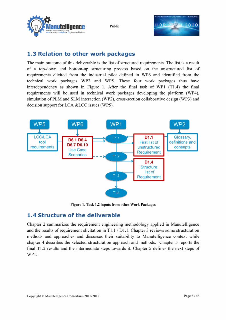
1.3 Relation to other work packages The main outcome of this deliverable is the list of structured requirements. The list is a result of a top-down and bottom-up structuring process based on the unstructured list of requirements elicited from the industrial pilot defined in WP6 and identified from the technical work packages WP2 and WP5. These four work packages thus have interdependency as shown in Figure 1. After the final task of WP1 (T1.4) the final requirements will be used in technical work packages developing the platform (WP4), simulation of PLM and SLM interaction (WP2), cross-section collaborative design (WP3) and decision support for LCA &LCC issues (WP5).
Figure 1. Task 1.2 inputs from other Work Packages
1.4 Structure of the deliverable Chapter 2 summarizes the requirement engineering methodology applied in Manutelligence and the results of requirement elicitation in T1.1 / D1.1. Chapter 3 reviews some structuration methods and approaches and discusses their suitability to Manutelligence context while chapter 4 describes the selected structuration approach and methods. Chapter 5 reports the final T1.2 results and the intermediate steps towards it. Chapter 5 defines the next steps of WP1.
WP1
T1.1 D1.1First list of
unstructured Requirement
T1.2
T1.3
T1.4
D1.4Structure
list of Requirement
WP6
D6.1 D6.4 D6.7 D6.10Use Case Scenarios
WP5
LCC/LCAtool
requirements
WP2
Glossary, definitions and
consepts
Public
Copyright � Manutelligence Consortium 2015-2018 Page 7 / 46
2 Requirements engineering approach in Manutelligence
In Manutelligence Deliverable D1.1 the underlying methods for Requirements engineering (RE) for Product Service System (PSS) were described in detail. Based on this background knowledge the Requirements engineering process to be used in Manutelligence was developed and described. The following section presents a summary of the whole RE process.
2.1 Requirements engineering process used in Manutelligence
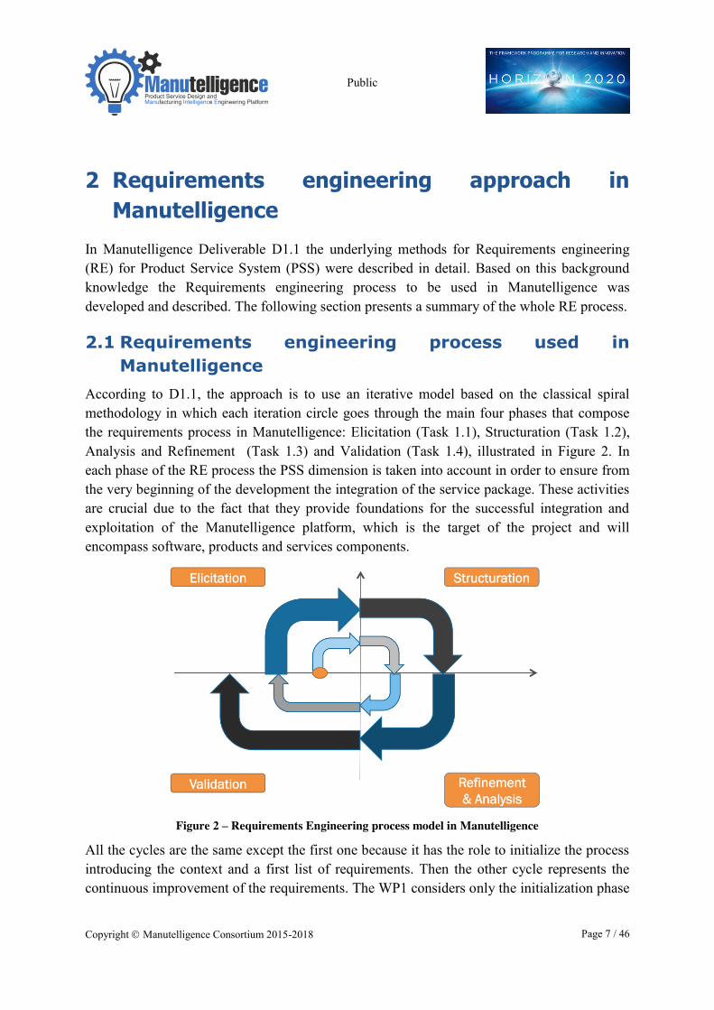
According to D1.1, the approach is to use an iterative model based on the classical spiral methodology in which each iteration circle goes through the main four phases that compose the requirements process in Manutelligence: Elicitation (Task 1.1), Structuration (Task 1.2), Analysis and Refinement (Task 1.3) and Validation (Task 1.4), illustrated in Figure 2. In each phase of the RE process the PSS dimension is taken into account in order to ensure from the very beginning of the development the integration of the service package. These activities are crucial due to the fact that they provide foundations for the successful integration and exploitation of the Manutelligence platform, which is the target of the project and will encompass software, products and services components.
Figure 2 – Requirements Engineering process model in Manutelligence
All the cycles are the same except the first one because it has the role to initialize the process introducing the context and a first list of requirements. Then the other cycle represents the continuous improvement of the requirements. The WP1 considers only the initialization phase
Public
Copyright � Manutelligence Consortium 2015-2018 Page 8 / 46
because the further cycles start in parallel with the integration of the platform and are considered in other WPs.
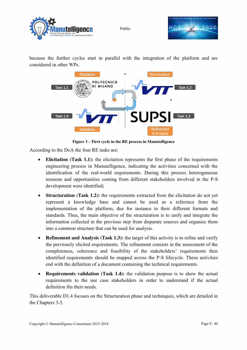
Figure 3 – First cycle in the RE process in Manutelligence According to the DoA the four RE tasks are:
x Elicitation (Task 1.1): the elicitation represents the first phase of the requirements engineering process in Manutelligence, indicating the activities concerned with the identification of the real-world requirements. During this process heterogeneous tensions and opportunities coming from different stakeholders involved in the P-S development were identified;
x Structuration (Task 1.2): the requirements extracted from the elicitation do not yet represent a knowledge base and cannot be used as a reference from the implementation of the platform, due for instance to their different formats and standards. Thus, the main objective of the structuration is to unify and integrate the information collected in the previous step from disparate sources and organize them into a common structure that can be used for analysis.
x Refinement and Analysis (Task 1.3): the target of this activity is to refine and verify the previously elicited requirements. The refinement consists in the assessment of the completeness, coherence and feasibility of the stakeholders’ requirements then identified requirements should be mapped across the P-S lifecycle. These activities end with the definition of a document containing the technical requirements.
x Requirements validation (Task 1.4): the validation purpose is to show the actual requirements to the use case stakeholders in order to understand if the actual definition fits their needs.
This deliverable D1.4 focuses on the Structuration phase and techniques, which are detailed in the Chapters 3-5.
Public
Copyright � Manutelligence Consortium 2015-2018 Page 9 / 46
2.2 Results from Task 1.1 Requirements Elicitation in Manutelligence
The main subject of Deliverable D1.1 was the Elicitation (Task 1.1), which is the first phase of the requirement process. The deliverable first presented an analysis of the state of art of the existing RE approaches suited for holistic Product Service in order to identify which approach can be adopted in the scope of the Manutelligence project. Then special emphasis was placed on the requirements elicitation methods in order to define the suitable techniques for gathering requirements as well as the users and stakeholders to be involved.
The applied elicitation techniques addressed basically a top-down scenario-based approach considering the four industrial pilots detailed in WP6 and the technical work packages such as WP2 and WP5. The result of this first elicitation phase is a list of unstructured requirements from each industrial pilot and from the technical work packages.
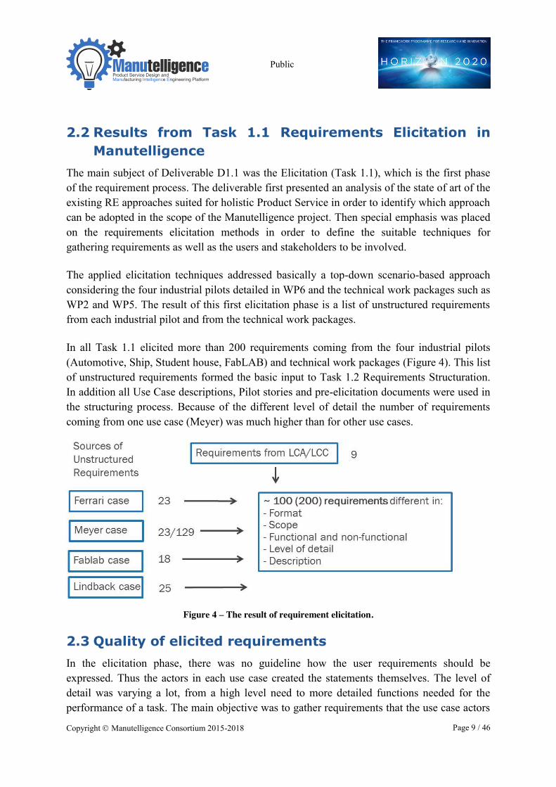
In all Task 1.1 elicited more than 200 requirements coming from the four industrial pilots (Automotive, Ship, Student house, FabLAB) and technical work packages (Figure 4). This list of unstructured requirements formed the basic input to Task 1.2 Requirements Structuration. In addition all Use Case descriptions, Pilot stories and pre-elicitation documents were used in the structuring process. Because of the different level of detail the number of requirements coming from one use case (Meyer) was much higher than for other use cases.
Figure 4 – The result of requirement elicitation.
2.3 Quality of elicited requirements In the elicitation phase, there was no guideline how the user requirements should be expressed. Thus the actors in each use case created the statements themselves. The level of detail was varying a lot, from a high level need to more detailed functions needed for the performance of a task. The main objective was to gather requirements that the use case actors
Public
Copyright � Manutelligence Consortium 2015-2018 Page 10 / 46
saw important to implement the user scenarios presented in WP6 deliverables. It is not expected that all the requirements and scenarios will be implemented during Manutelligence project. The prioritization and selection will be made by the use cases later in the project (T1.3-4), but, to give a better view to requirements of the platform, it was seen useful to describe also user scenarios and requirements that are necessarily not implemented in this project, but which are partly potential development objects in the future.
There are several approaches and metrics to measure quality of requirements. For example, in (UTM 2015) a checklist for requirement quality is presented. The checklist includes questions about the following criteria:
- Correctness - Completeness - Clarity - Consistency - Verifiability - Traceability - Feasibility - Design independency - Atomicity (exactly one requirement).
As defined in Manutelligence DoA, the next task, T1.3 will carry out an analysis of the requirements, relating to completeness, consistency and feasibility. Thus they are not discussed here. Regarding the other quality criteria some comments are given below in Table 1 at high level.
As it can be seen in the table, in many cases the requirements are not very clear and detailed and thus also not easily verifiable. Thus, in addition to the listed requirements, other information, like the use case scenario etc., are needed to properly understand the need. Because of this, close collaboration between the use cases and the platform development in the development phase is needed.
Table 1. Requirement qualities.
Quality criteria Quality of Manutelligence requirements
Correctness: Does the requirement specify a true need, desire, or obligation? Have you identified the root cause that necessitates the requirement?
All the requirements are based on end user needs and scenarios. Thus they can be considered as true needs. In most cases it is possible to understand why the requirement is needed.
Clarity: Is the requirement unambiguous and not confusing? Does everyone agree on the meaning of the requirement?
The requirements are not always very clear even if they are understandable for the use case actors. For outsiders they are often not easy to understand properly.
Public
Copyright � Manutelligence Consortium 2015-2018 Page 11 / 46
Verifiability: Can you determine whether the system satisfies the requirement? Is it possible to define a clear, unambiguous pass or fail criterion? Is it possible to determine whether the requirement has been met through inspection, analysis, demonstration, or test?
This question is related to the above question about clarity. If the requirement is not very clear it is hard to assess the verifiability. Some of the requirements seem possible to verify, while for others the situation is not as clear.
Traceability: Is the requirement uniquely identified so that it can be referenced unambiguously?
All the requirements have been given an id which is kept during the process to allow tracing back.
Design independency: Are all requirements that impose constraints on the design, thereby limiting design options, justified? Is the requirement stated in such a way that there is more than one way that it can be satisfied?
There were typically no constraints addressed for the requirements. Thus the requirements can be satisfied with different solutions.
Atomicity: Does the requirement statement define exactly one requirement? Is the requirement statement free of conjunctions (and, or, but) that could indicate multiple requirements?
Most of the requirements are not atomic. They typically include several requirements.
Public
Copyright � Manutelligence Consortium 2015-2018 Page 12 / 46
3 Approaches for structuration
3.1 Definition of structuration As stated in the Manutelligence project plan, the main objective of structuration is to unify and integrate the information collected in the previous step from disparate sources and organize them into a common structure that can be used for analysis. Also specific preparation activities of the information may be needed to support the structuring. After appropriate structuration, user requirements can be refined and analysed.
Requirements Classification is often used in the same meaning as Structuration. Requirements can be classified on a number of dimensions (SWEBOK Guide V3.0) like functional or non-functional, or whether the requirement is derived from one or more high-level requirements or an emergent property.
By the BABOK Guide (v2.0) (http://www.iiba.org/babok-guide.aspx) requirements are classified in the following categories: Business, Stakeholder, Solution, Functional, Non-Functional and Transition Requirements. Basically the data and objective defines the method used and the classification’s level of detail.
In classification one or more dimensions are used. Each of these dimensions has its classes. Usually each dimension originates from the needs of the analysist and aims to provide structured information. For example one could classify Lego bricks by colour or size. Classification by colour provides valuable information for a person responsible of pigments while on the other hand classification by size helps planning logistics.
For Manutelligence purposes the classification of requirements is the key to manage the heterogeneous set of requirements.
3.2 Review of existing approaches There are several methods that are used for data structuration. The original Structuration theory by Anthony Giddens was given as: “The theory of structuration is a social theory of the creation and reproduction of social systems that is based in the analysis of both structure and agents” (Wikipedia permanent link
https://en.wikipedia.org/w/index.php?title=Structuration_theory&oldid=676026290). This is not suitable for Manutelligence type of data since it originates from the social theory and is not designed for the system development and requirement type of data analysis.
Structuration methods can be divided into two different categories: (1) Quantitative methods and (2) Qualitative methods. Quantitative methods basically deal with the numbers and statistics. Thus they are not applicable for Manutelligence due to the limited amount and non-numerical quality of data. Also in Manutelligence the data is case specific and context
Public
Copyright � Manutelligence Consortium 2015-2018 Page 13 / 46
dependent thus giving more or less different meanings to the same terms. This type of data requires qualitative methods and interpretation based on researchers’ know-how.
One of the popular qualitative methods is the Cluster Analysis (see e.g. Kaufman, Rousseeuw, 1990). “Clustering is the division of data into groups of similar objects. In clustering, some details are disregarded in exchange for data simplification. Clustering can be viewed as a data modelling technique that provides for concise summaries of the data. Clustering is therefore related to many disciplines and plays an important role in a broad range of applications. The applications of clustering usually deal with large datasets and data with many attributes.” (Berkhin, 2006) Methods used in automated clustering are e.g. case-based reasoning (CBR) and cluster analysis. In demographics clustering is based on the characteristics of a population like ethnicity or economics. For Manutelligence, Cluster Analysis is however overly “quantitative” and statistical a method. It is based on the similarity or closeness in data and is not a workable method considering the small size and heterogeneousness of the available data set.
Thematic analysis is one of the most popular qualitative methods. The idea of the Thematic analysis method is to identify and define patterns or themes in the collected data. These patterns and themes are similar to the structures of data. The data can already have clear existing structures like questionnaires’ topics and questions that are guiding the respondents line of reasoning. These are thus given and can be a good start for structuration. However, the data can provide a better or different structuration to consider. Deductive and Inductive approaches can be applied here in connection with the Thematic analysis but they need to be adapted due to the characteristics of Manutelligence data and context (see e.g. Fereday and Muir-Cochrane, 2006).
The six step process of Thematic analysis presented next is based on Aronson (Aronson, 1995).
1. Collect the data.
2. Patterns (of experiences) can be listed.
3. Identify all data that relate to the already classified patterns.
4. Combine and catalogue related patterns into sub-themes.
5. Themes are identified by "bringing together components or fragments of ideas or experiences, which often are meaningless when viewed alone.
6. Build a valid argument for choosing the themes.
Another list of Thematic analysis steps is presented in Wikipedia (permanent link: https://en.wikipedia.org/w/index.php?title=Thematic_analysis&oldid=649103484):
1. Familiarization with data
Public
Copyright � Manutelligence Consortium 2015-2018 Page 14 / 46
2. Generating initial codes
3. Searching for themes among codes
4. Reviewing themes
5. Defining and naming themes
6. Producing the final report
For Manutelligence Thematic analysis is a good starting point. In Manutelligence data and context provide preliminary structures to build on or least to check if the existing structures can be useful when building the final structure. Manutelligence structuration approach and method presented next are based on several data analysis and classification methods to match the nature and quality of data and Manutelligence requirements engineering process.
Public
Copyright � Manutelligence Consortium 2015-2018 Page 15 / 46
4 Manutelligence approach for requirement structuration
4.1 Handling of heterogeneous data The set of Manutelligence requirements has some characteristic features. Here the starting point of the system development is a large existing software platform. This platform has functionalities and properties that are not part of Manutelligence platform development or requirement engineering process. In Manutelligence during the structuration phase we work only with the new user requirements collected from the four cases and it is not the aim to form a complete set of structured software requirements for the platform.
This makes the Manutelligence approach different from the basic software requirements definition cases that start from the scratch (new application or module) or have the description or original user requirements of the existing platform available.
From the structuration point of view this makes it ineffectual to use data flow diagrams, process modelling, or relationship identifying methods in Manutelligence. The user requirements are partly incoherent since they are new requirements for existing software. Thus the focus here is in the classification or categorization of the requirements and in the comparability of data across the cases.
All four Manutelligence cases are about different design, manufacturing and service processes and / or phases of the processes. This is challenging from the structuration point of view, especially since the data collection has been executed in four parallel processes and by different groups.
Manutelligence cases are from four different industries: automotive, maritime, 3D-printing and construction. Different sectors bring along different terminologies. The companies represent different company size and there are also differences in their preparedness for the utilisation of information technology. All cases are also from different countries: Italy, Finland/Germany, Spain and Sweden. Using natural language is challenging in itself. ESA Guide to the user requirements definition phase (1995) mentions that “Natural language is rich and accessible but inconsistency and ambiguity are more likely”. None of Manutelligence cases is in English speaking countries, thus forcing researchers and interviewees to translate the requirements and case stories into English from their native language. This translation can take place either after an interview by the interviewer or in the minds of the interviewees. Therefore all four cases originate from different contexts, cultures, languages and product-service systems.
Public
Copyright � Manutelligence Consortium 2015-2018 Page 16 / 46
Also the researchers (interviewers) are from different cultures with different academic and professional backgrounds. This affects the homogeneity of interview interpretations across the cases for potential personal biases.
Given all above, the four datasets available are very difficult to compare though the focus in all is the functionalities of an information system platform. Therefore the structuration and analysis of the requirements is difficult to automate and will require manual and iterative processing of data. The structuration phase is performed once only but the discussion and refinement of the structure will continue throughout the Manutelligence process.
In the design of Manutelligence structuration method this has been taken into account. The method will start with a rough classification of the requirements to allow learning take place and to give researchers time to familiarize with the data. If one would try and classify the requirements on a detailed level at once this would probably cause discrepancies and uncertainties within and between the classes. After the first classification the requirements can be sorted in more detail and additional structures (nodes) can be created into the classification hierarchy.
The requirements in some cases were reported more in detail and deeper hierarchies were used. This required some flattening so that the requirements between cases were more comparable and commensurate. The flattening took place by taking the higher level requirement as a starting point to be modified to contain sub-requirement information if necessary.
Traceability of data must be maintained throughout the requirements engineering process. This is important especially since in Manutelligence the requirements come from different cases and different industrial contexts. Also the process has several steps and its being executed by several partners. In the validation task the case owners need to be able to trace back to their own original requirements to see if what they did mean was interpreted and classified correctly. Therefore all requirements must have a unique identifier that follows through the process.
4.2 Manutelligence structuration method Here the method used is shortly described to give an overview of the different phases and tasks. The use in the Manutelligence case with real data is presented in chapter 5.
In the beginning, the data must be prepared by giving each requirement a unique identifier that also connects it to the original case. This identifier must follow the requirement throughout the process so that the original requirement can always be traced back. Keep the format short to make the identifier practical and easy to use.
Task 1: Top-down approach, identify given concepts and structures
Public
Copyright � Manutelligence Consortium 2015-2018 Page 17 / 46
Identify the given structures available in the project. These can be found for example in the interviews or questionnaires. Compare the structures to find similarities. These similarities do not have to be exactly the same but on the same dimension like for example different process phases of product-service lifecycles. Evaluate the usefulness of each one from the requirements engineering point of view. To reduce the number of dimensions, merge the similar ones into one or more generic ones that best represent the remaining dimensions.
Task 2: Bottom-up approach, structures emerging from the data
This task is close to the Thematic analysis. Familiarizing with the data is important also in other tasks but in this one has to understand not only individual requirements but also their relation to the context and case characteristics.
The bottom-up approach means analysing the unstructured requirements to identify similarities, categories and structures. As in Task 1 the goal is to form a generic structure or hierarchy of categories that suits for all use cases and supports the development of the Manutelligence platform. In practice this means that too simple a structure is not useful since too many requirements will remain under each category but also creating too many categories will lose the idea of processing data to simplify and combine information into a better exploitable form.
Task 3: Integrating top-down and bottom-up
After the first two tasks the information available both from the given structures (top-down) and from the list of unstructured requirements (bottom-up) has been processed. By comparing the information now available, relations, similarities and differences are identified. The final structure can be formed, based on understanding the knowledge from the both approaches and the complete data.
Task 4: Organize requirements to structures
In this task the created structure is in a way tested by placing the original unstructured requirements in the structure. However, it is practically impossible to create a structure where all requirements can be placed without uncertainty. It is also possible that a single requirement can be placed in more than one category.
If the placement of requirements is difficult or if several requirements are put into more than one category the structuration should be revised. One possibility is to create new categories or subcategories if needed but they have to be justified. If it becomes clear that the structuration is not working as intended and the dimensions selected do not fit the data then one should consider starting the structuration process from the beginning.
Task 5: Aggregate requirements
Some of the requirements under one category can practically mean the same thing. In such case it is practical for the further analysis to aggregate these into a new requirement that best
Public
Copyright � Manutelligence Consortium 2015-2018 Page 18 / 46
represents the meaning of the aggregated requirements. It is important to maintain the integrity of data by not removing the links to the original requirements being aggregated.
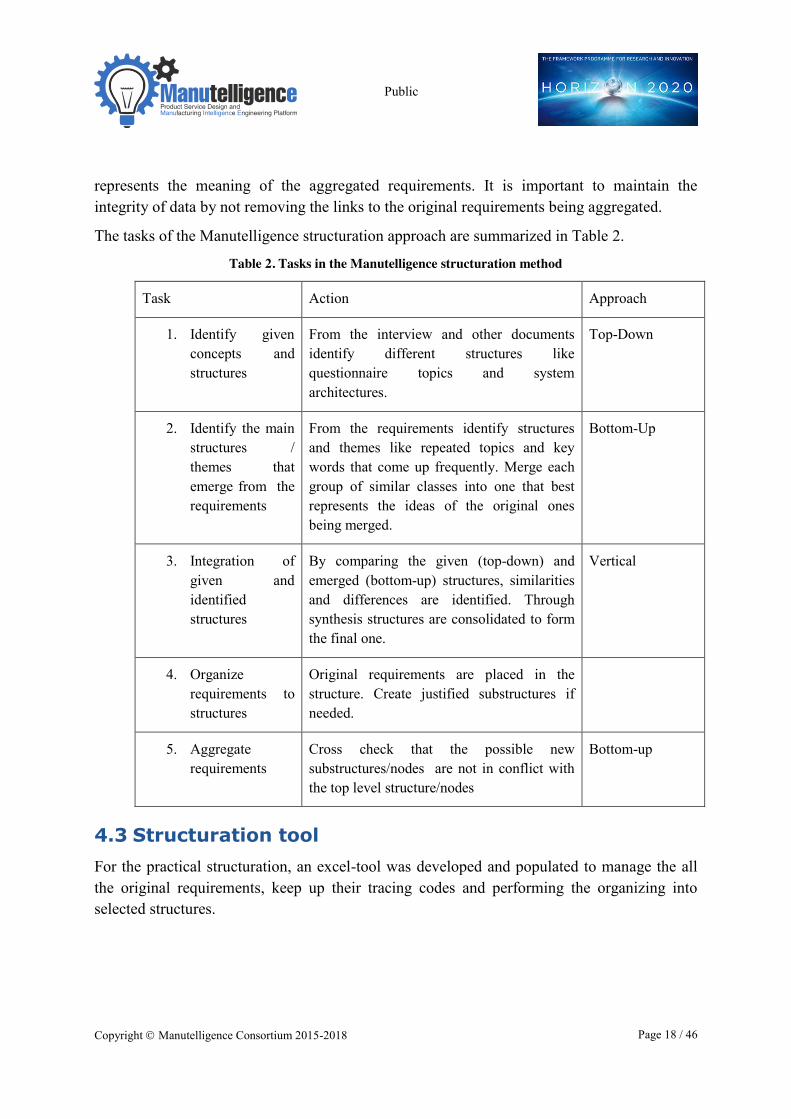
The tasks of the Manutelligence structuration approach are summarized in Table 2.
Table 2. Tasks in the Manutelligence structuration method
Task Action Approach
1. Identify given concepts and structures
From the interview and other documents identify different structures like questionnaire topics and system architectures.
Top-Down
2. Identify the main structures / themes that emerge from the requirements
From the requirements identify structures and themes like repeated topics and key words that come up frequently. Merge each group of similar classes into one that best represents the ideas of the original ones being merged.
Bottom-Up
3. Integration of given and identified structures
By comparing the given (top-down) and emerged (bottom-up) structures, similarities and differences are identified. Through synthesis structures are consolidated to form the final one.
Vertical
4. Organize requirements to structures
Original requirements are placed in the structure. Create justified substructures if needed.
5. Aggregate requirements
Cross check that the possible new substructures/nodes are not in conflict with the top level structure/nodes
Bottom-up
4.3 Structuration tool For the practical structuration, an excel-tool was developed and populated to manage the all the original requirements, keep up their tracing codes and performing the organizing into selected structures.
Public
Copyright � Manutelligence Consortium 2015-2018 Page 19 / 46
5 Results: from unstructured to structured requirements
5.1 Definition of structures The structuring or categorization of the requirements was performed by reconciling the results of top-down and bottom-up approaches. The top-down starts from the structures and concepts given by the project and the bottom-up from the identified unstructured requirements.
Top-down approach, given concepts and structures
Manutelligence project is focused on product-service design using manufacturing intelligence and development of a platform to support the whole product service lifecycle. Thus the main concepts of the project include: product, service, lifecycle and the platform. The unstructured requirements are directed towards the Manutelligence platform.
The requirement elicitation process included two questionnaires for the use cases: a pre-elicitation questionnaire and a questionnaire about the industrial practices in product and service development and data management. The pre-elicitation questionnaire asked about the use case view to requirements, about the current product-service provision and the expected benefits. The second questionnaire was more extensive, with the main sections about design process, managing knowledge, product-service offering and evaluating the PSS lifecycle.
Thus, from Manutelligence context the following main concepts can be identified:
- Product service (PS) (answering to question WHAT)
- PS Lifecycle (WHEN)
- PS actors / stakeholders (BY WHOM)
- PS related knowledge/ information / data
- Platform (HOW; this is for what the requirements are)
Based on these, from top-down there are several alternatives for requirement categorization, for example based on product service type, information type, stakeholders etc. Product service –type of categorization would not support the integration of requirements of different use cases. Classification according to the stakeholders would be difficult as in most cases the objective is to support the information sharing, communication and collaboration between different stakeholders in all tasks.
Public
Copyright � Manutelligence Consortium 2015-2018 Page 20 / 46
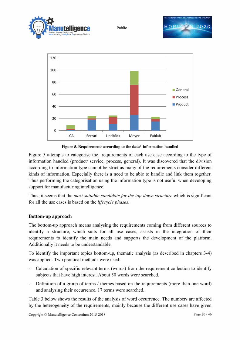
Figure 5. Requirements according to the data/ information handled
Figure 5 attempts to categorise the requirements of each use case according to the type of information handled (product/ service, process, general). It was discovered that the division according to information type cannot be strict as many of the requirements consider different kinds of information. Especially there is a need to be able to handle and link them together. Thus performing the categorisation using the information type is not useful when developing support for manufacturing intelligence.
Thus, it seems that the most suitable candidate for the top-down structure which is significant for all the use cases is based on the lifecycle phases.
Bottom-up approach
The bottom-up approach means analysing the requirements coming from different sources to identify a structure, which suits for all use cases, assists in the integration of their requirements to identify the main needs and supports the development of the platform. Additionally it needs to be understandable.
To identify the important topics bottom-up, thematic analysis (as described in chapters 3-4) was applied. Two practical methods were used:
- Calculation of specific relevant terms (words) from the requirement collection to identify subjects that have high interest. About 50 words were searched.
- Definition of a group of terms / themes based on the requirements (more than one word) and analysing their occurrence. 17 terms were searched.
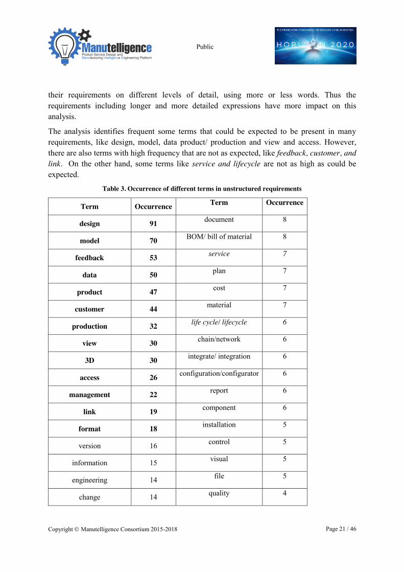
Table 3 below shows the results of the analysis of word occurrence. The numbers are affected by the heterogeneity of the requirements, mainly because the different use cases have given
0
20
40
60
80
100
120
LCA Ferrari Lindbäck Meyer Fablab
General
Process
Product
Public
Copyright � Manutelligence Consortium 2015-2018 Page 21 / 46
their requirements on different levels of detail, using more or less words. Thus the requirements including longer and more detailed expressions have more impact on this analysis.
The analysis identifies frequent some terms that could be expected to be present in many requirements, like design, model, data product/ production and view and access. However, there are also terms with high frequency that are not as expected, like feedback, customer, and link. On the other hand, some terms like service and lifecycle are not as high as could be expected.
Table 3. Occurrence of different terms in unstructured requirements
Term Occurrence Term Occurrence
design 91 document 8
model 70 BOM/ bill of material 8
feedback 53 service 7
data 50 plan 7
product 47 cost 7
customer 44 material 7
production 32 life cycle/ lifecycle 6
view 30 chain/network 6
3D 30 integrate/ integration 6
access 26 configuration/configurator 6
management 22 report 6
link 19 component 6
format 18 installation 5
version 16 control 5
information 15 visual 5
engineering 14 file 5
change 14 quality 4
Public
Copyright � Manutelligence Consortium 2015-2018 Page 22 / 46
inspect 14 virtual 4
status 13 platform 4
structure 10 conversion 4
CAD 10 automatic 4
process 10 sustainability 3
manufacturing 9 contract 3
test 9 supplier 2
check 9 security 2
drawing 8 communication 2
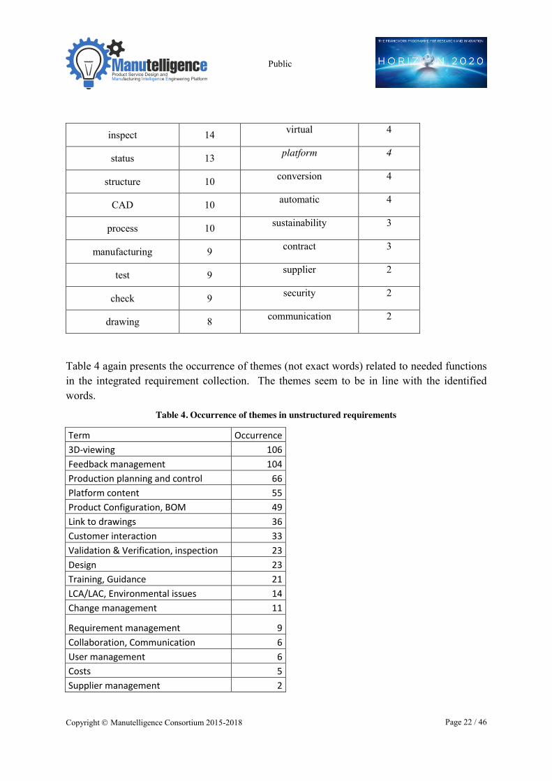
Table 4 again presents the occurrence of themes (not exact words) related to needed functions in the integrated requirement collection. The themes seem to be in line with the identified words.
Table 4. Occurrence of themes in unstructured requirements
Term Occurrence 3D-viewing 106 Feedback management 104 Production planning and control 66 Platform content 55 Product Configuration, BOM 49 Link to drawings 36 Customer interaction 33 Validation & Verification, inspection 23 Design 23 Training, Guidance 21 LCA/LAC, Environmental issues 14 Change management 11
Requirement management 9 Collaboration, Communication 6 User management 6 Costs 5 Supplier management 2
Public
Copyright � Manutelligence Consortium 2015-2018 Page 23 / 46
Three of the four use cases already had an internal grouping of their requirements. The grouping was different for different use cases, but they mainly were focused on a specific life cycle phase. Different life cycle phases seemed to have different weighting; as a whole the engineering/ design / product development phase had most requirements.
Integrating top-down and bottom-up
The selected approach for structuring top-down was based on product service life cycle. The main intrinsic grouping in the use cases also followed the life cycle approach. In the thematic analysis some of the words and themes identified are clearly related to one specific lifecycle phase and some are related to more than one phase. The thematic analysis also revealed different types of functions, especially related to the design phase. Design phase is not only of engineering/ design but also preparing and using the designed product model for intelligent actions in different life cycle phases. Thus, when selecting the high level structure for the integrated requirements, it was seen useful to divide the design phase functions to two groups; those related to the real design phase (creation of the product model) and those using the product model for linking additional information / documents, to perform analysis & checking and to prepare for life cycle services.
The defined five high level requirement categories are described below (origin: F-Ferrari, L-Lindback, M-Meyer, Fa-Fablab, LCA-WP5 LCA):
1. Product & service design into model
This includes all the requirements related to Product development / design/engineering – building the 3D model for the product, for example: product requirement management (F), product configuration (F+L), design based on construction method (M), creation and conversion of design for 3D printers (Fa), design changes and version management (F, L).
2. Model checking and linking
This includes checking and analysing the product using the 3D model and linking information / feedback to it, for example: tests, analysis, simulation -> data into the platform (F), cost calculation (L), LCA/LCC-analysis (LCA), sustainability analysis (Fa), customer feedback through 3D and gaming experience (M).
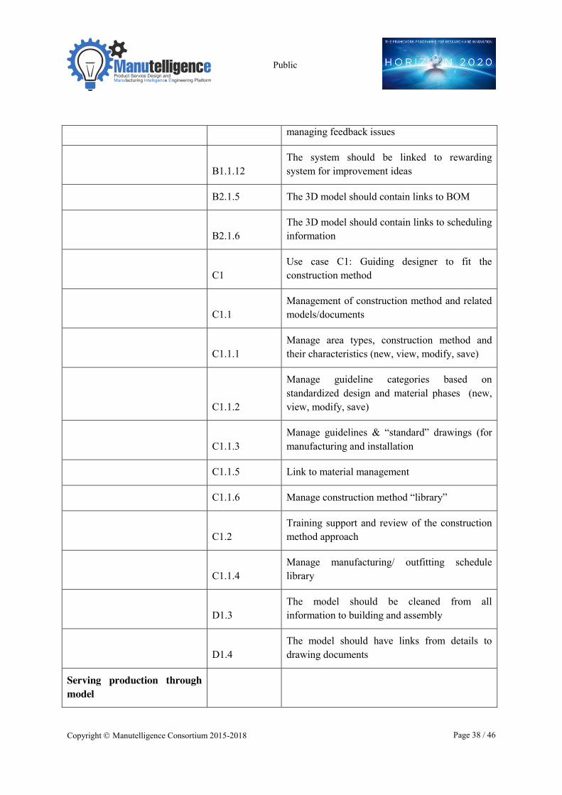
3. Serving production through model
This includes using the 3D-model to support manufacturing/ construction /installation, for example installation support (M), inspection support (M), production feedback (M), project planning & management (L), developing the production cycle (Fa).
4. Model for operation & user services
Public
Copyright � Manutelligence Consortium 2015-2018 Page 24 / 46
This includes all the requirements for the operation & usage phase, like measurement with sensors and IoT (L), operation feedback (M), monitoring (M) which use the product model and related information.
5. Sharing & non-functional requirements
This includes all non-functional requirements, also related to sharing and access to information, like- access to ship model and needed information through it (M), all information embedded and managed in the platform (F), sharing Fablab-models (Fa) and security aspects.
Categories 1-3 belong to the Beginning of Life and 4 to Middle of Life. We have identified no requirements for the End of Life.
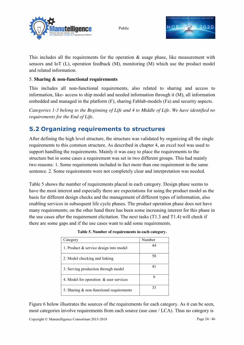
5.2 Organizing requirements to structures After defining the high level structure, the structure was validated by organizing all the single requirements to this common structure. As described in chapter 4, an excel tool was used to support handling the requirements. Mainly it was easy to place the requirements to the structure but in some cases a requirement was set in two different groups. This had mainly two reasons: 1. Some requirements included in fact more than one requirement in the same sentence. 2. Some requirements were not completely clear and interpretation was needed. Table 5 shows the number of requirements placed in each category. Design phase seems to have the most interest and especially there are expectations for using the product model as the basis for different design checks and the management of different types of information, also enabling services in subsequent life cycle phases. The product operation phase does not have many requirements; on the other hand there has been some increasing interest for this phase in the use cases after the requirement elicitation. The next tasks (T1.3 and T1.4) will check if there are some gaps and if the use cases want to add some requirements.
Table 5. Number of requirements in each category.
Category Number
1. Product & service design into model 44
2. Model checking and linking 58
3. Serving production through model 41
4. Model for operation & user services 9
5. Sharing & non-functional requirements 33
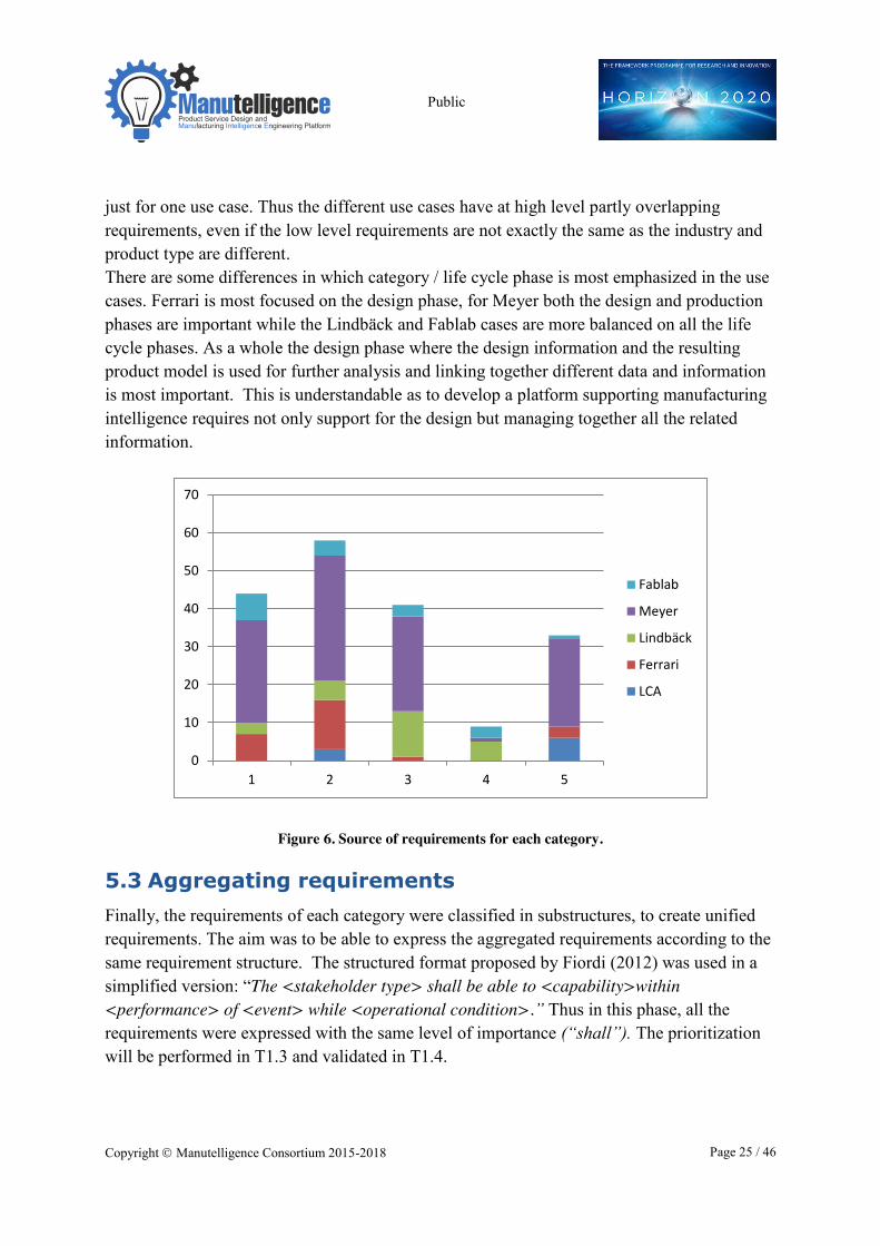
Figure 6 below illustrates the sources of the requirements for each category. As it can be seen, most categories involve requirements from each source (use case / LCA). Thus no category is
Public
Copyright � Manutelligence Consortium 2015-2018 Page 25 / 46
just for one use case. Thus the different use cases have at high level partly overlapping requirements, even if the low level requirements are not exactly the same as the industry and product type are different. There are some differences in which category / life cycle phase is most emphasized in the use cases. Ferrari is most focused on the design phase, for Meyer both the design and production phases are important while the Lindbäck and Fablab cases are more balanced on all the life cycle phases. As a whole the design phase where the design information and the resulting product model is used for further analysis and linking together different data and information is most important. This is understandable as to develop a platform supporting manufacturing intelligence requires not only support for the design but managing together all the related information.
Figure 6. Source of requirements for each category.
5.3 Aggregating requirements Finally, the requirements of each category were classified in substructures, to create unified requirements. The aim was to be able to express the aggregated requirements according to the same requirement structure. The structured format proposed by Fiordi (2012) was used in a simplified version: “The <stakeholder type> shall be able to <capability>within <performance> of <event> while <operational condition>.” Thus in this phase, all the requirements were expressed with the same level of importance (“shall”). The prioritization will be performed in T1.3 and validated in T1.4.
0
10
20
30
40
50
60
70
1 2 3 4 5
Fablab
Meyer
Lindbäck
Ferrari
LCA
Public
Copyright � Manutelligence Consortium 2015-2018 Page 26 / 46
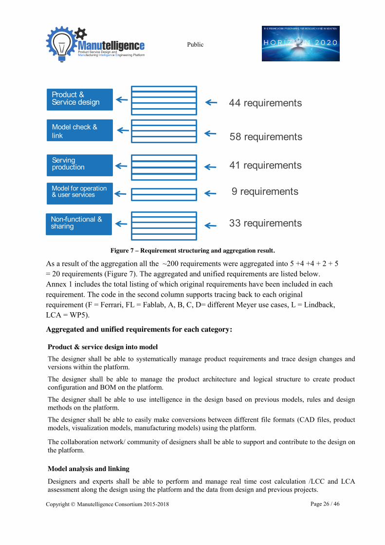
Figure 7 – Requirement structuring and aggregation result.
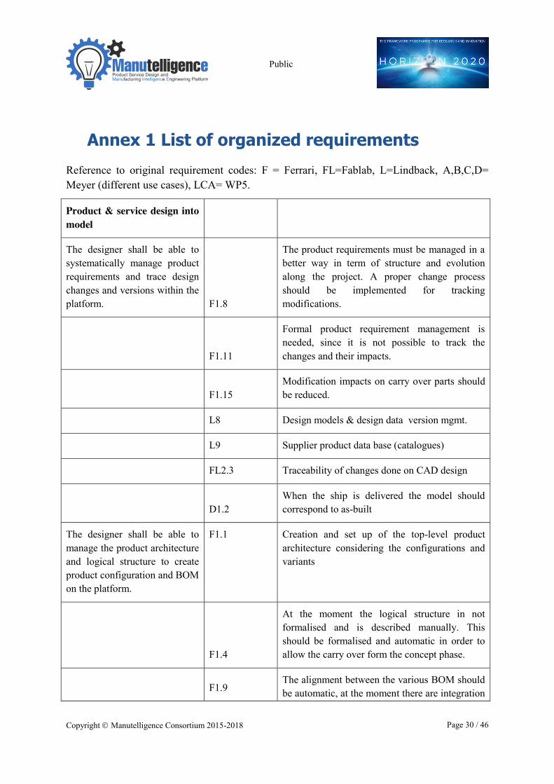
As a result of the aggregation all the ~200 requirements were aggregated into 5 +4 +4 + 2 + 5 = 20 requirements (Figure 7). The aggregated and unified requirements are listed below. Annex 1 includes the total listing of which original requirements have been included in each requirement. The code in the second column supports tracing back to each original requirement (F = Ferrari, FL = Fablab, A, B, C, D= different Meyer use cases, L = Lindback, LCA = WP5).
Aggregated and unified requirements for each category:
Product & service design into model The designer shall be able to systematically manage product requirements and trace design changes and versions within the platform.
The designer shall be able to manage the product architecture and logical structure to create product configuration and BOM on the platform.
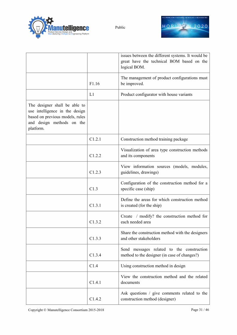
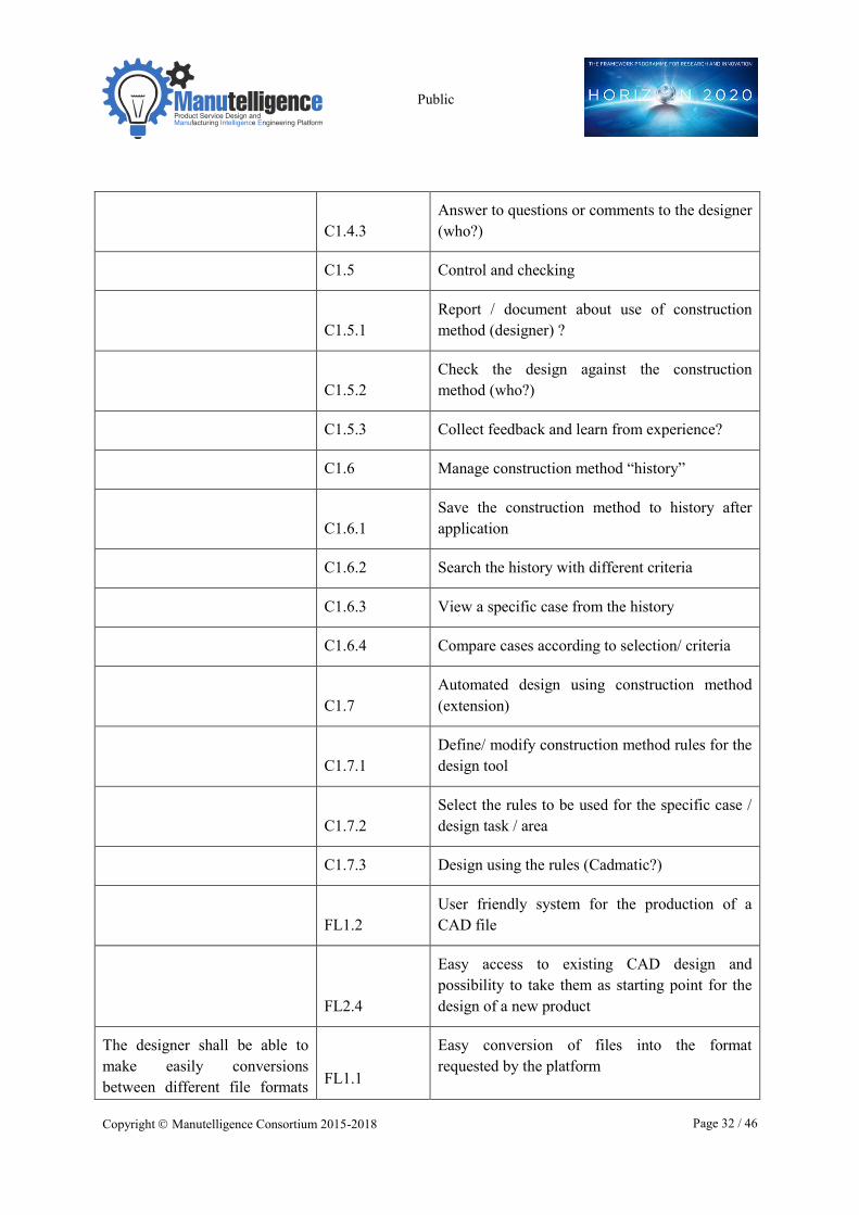
The designer shall be able to use intelligence in the design based on previous models, rules and design methods on the platform.
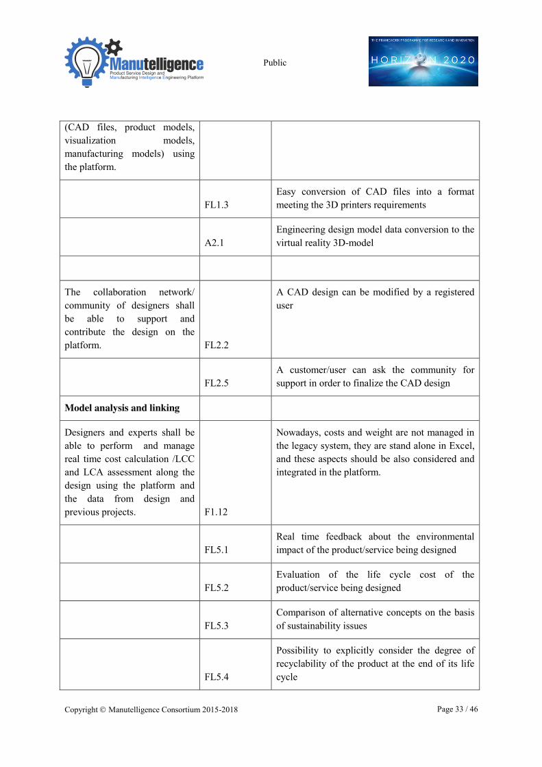
The designer shall be able to easily make conversions between different file formats (CAD files, product models, visualization models, manufacturing models) using the platform.
The collaboration network/ community of designers shall be able to support and contribute to the design on the platform.
Model analysis and linking
Designers and experts shall be able to perform and manage real time cost calculation /LCC and LCA assessment along the design using the platform and the data from design and previous projects.
Product & Service design
Model check & link
Servingproduction
Model for operation& user services
Non-functional & sharing
44 requirements
58 requirements
41 requirements
9 requirements
33 requirements
Public
Copyright � Manutelligence Consortium 2015-2018 Page 27 / 46
The designer / analyzer shall be able to link and manage all the results of (quality) tests and simulations to the platform product model.
The customer shall be able to view the visual product model (including virtual walk / driving) and give feedback on it using the platform.
The designer and the production shall be able to link and manage information, data and documents in the product model using the platform.
Serving production through model
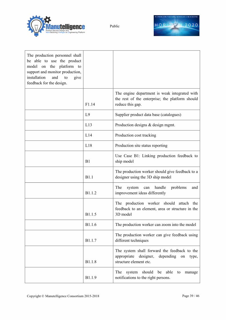
The production personnel shall be able to use the product model on the platform to support and monitor production, installation and to give feedback for the design.
Project manager shall be able to use the model on the platform to plan, monitor and manage the contract and the production.
The manufacturer/ production coordinator shall be able to manage the production resources and suppliers using the platform.
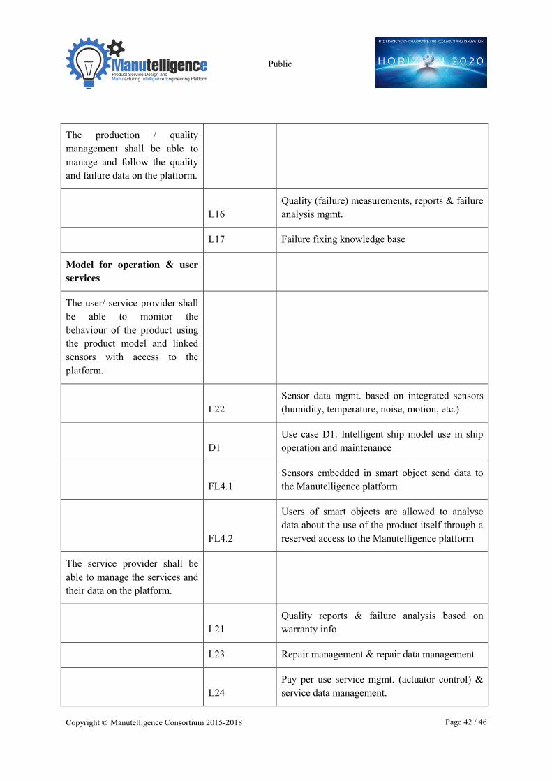
The production / quality management shall be able to manage and follow the quality and failure data on the platform.
Model for operation & user services The user/ service provider shall be able to monitor the behaviour of the product using the product model and linked sensors with access to the platform.
The service provider shall be able to manage the services and their data on the platform.
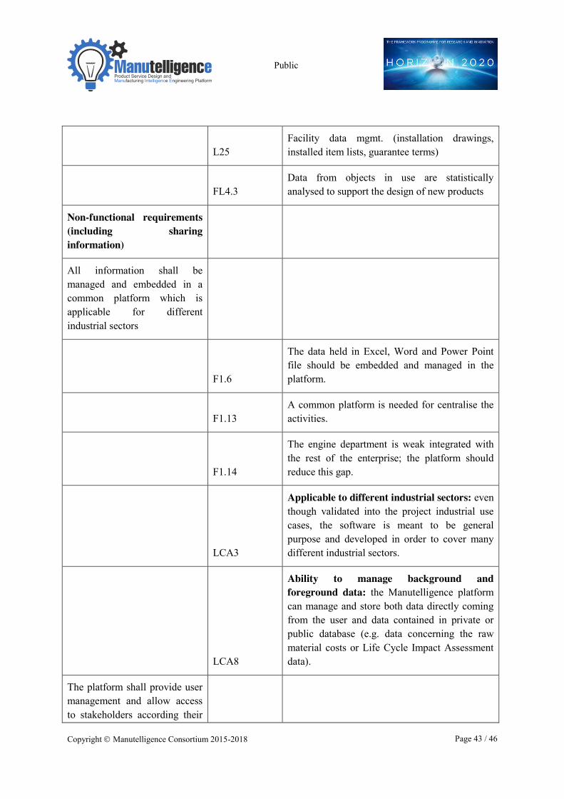
Non-functional requirements (including sharing information) All information shall be managed and embedded in a common platform which is applicable for different industrial sectors.
The platform shall provide user management and allow access to stakeholders according their rights & needs.
The platform should support sharing and communication, also remotely/online/off-line.
The platform shall take care about data quality and security.
User interface of the platform services shall be easy to use.
Public
Copyright � Manutelligence Consortium 2015-2018 Page 28 / 46
6 Conclusion and Next steps
This deliverable has taken as an input the unstructured requirements collected in T1.1. Requirement elicitation and organized and aggregated them in a common structure with unified manner of presentation. The process and methods used are described in this deliverable. This transformation caused the about 200 unstructured requirements to be organized in five categories and aggregated as a whole to 20 requirements. Tracing back to original requirements has been preserved and no prioritization has been performed in this phase. Thus the aggregated requirements all use the same way of expression (“shall”).
The next step in WP1 is the T1.3 Requirement Refinement and Analysis. The task will use the results of T1.2, that is; the organized and aggregated list of requirements, taking into account also the original elicited requirements. The first task in the analysis is to check the current structuring to identify potential errors and inconsistencies and if needed, to make changes to the structure and organization developed in T1.2. The second task is the analysis of trade-off among requirements to highlight possible conflicting objectives that have to be taken into consideration for the prioritization. The prioritization criteria need to be defined. At the moment two main categories are identified: pilot-related criteria (what are the improved performance if a requirement is fulfilled?) and Manutelligence-related criteria (for example, higher priority will be assigned to those criteria that allow a further exploitation of the Manutelligence platform in other sectors after the end of the project). Some criteria could require the analysis of gaps like the identification of the effort needed to fulfil the requirement given the as-is level of development. The requirements are ranked using the criteria. It is possible that during the process need for detailing the requirements more is identified.
After the analysis, in T1.4 the unified and prioritized requirements are validated again by the original stakeholders who gave them. Thus the use case stakeholders may modify the prioritization. In this phase additional and updated information, also new requirements from the use cases may be added.
Beyond the final task of WP1 (T1.4) the final requirements will be used in technical work packages developing the platform (WP4), simulation of PLM and SLM interaction (WP2), cross-section collaborative design (WP3) and decision support for LCA &LCC issues (WP5), and in developing the use cases in WP6.
Public
Copyright � Manutelligence Consortium 2015-2018 Page 29 / 46
7 References Aronson, J. (1995). A Pragmatic View of Thematic Analysis.The Qualitative Report, 2(1), 1-3. Retrieved from http://nsuworks.nova.edu/tqr/vol2/iss1/3
BABOK Guide (v2.0) http://www.iiba.org/babok-guide.aspx.
Berkhin P. (2006). A Survey of Clustering Data Mining Techniques, Grouping Multidimensional Data, , pp 25-71.
Diev, S. (2007). Structuring complex requirements, ACM SIGSOFT Software Engineering Notes, Page 1, March 2007, Volume 32 Number 2
ESA Guide to the user requirements definition phase (1995).
Fereday, J., Muir-Cochrane, E., (2006). Demonstrating Rigor Using Thematic Analysis: A Hybrid Approach of Inductive and Deductive Coding and Theme Development, International Journal of Qualitative Methods, pp.80-92.
Fiordi, P. (2012). Proposal of a Requirements Process Model for complex IT development projects; POLITECNICO DI MILANO, Facoltà di Ingegneria dei Sistemi, Corso di Laurea Specialistica in Ingegneria Gestionale.
Kaufman, L. and Rousseeuw, P.J. (1990). Finding Groups in Data: An Introduction to Cluster Analysis. Wiley, New York.
UTM 2015. www.utm.mx/.../good_requirements_594ACCBD.htm, accessed 20.10.15
Wikipedia. permanent link https://en.wikipedia.org/w/index.php?title=Structuration_theory&oldid=676026290
https://en.wikipedia.org/w/index.php?title=Thematic_analysis&oldid=649103484
Public
Copyright � Manutelligence Consortium 2015-2018 Page 30 / 46
Annex 1 List of organized requirements
Reference to original requirement codes: F = Ferrari, FL=Fablab, L=Lindback, A,B,C,D= Meyer (different use cases), LCA= WP5.
Product & service design into model
The designer shall be able to systematically manage product requirements and trace design changes and versions within the platform. F1.8
The product requirements must be managed in a better way in term of structure and evolution along the project. A proper change process should be implemented for tracking modifications.
F1.11
Formal product requirement management is needed, since it is not possible to track the changes and their impacts.
F1.15
Modification impacts on carry over parts should be reduced.
L8 Design models & design data version mgmt.
L9 Supplier product data base (catalogues)
FL2.3 Traceability of changes done on CAD design
D1.2
When the ship is delivered the model should correspond to as-built
The designer shall be able to manage the product architecture and logical structure to create product configuration and BOM on the platform.
F1.1 Creation and set up of the top-level product architecture considering the configurations and variants
F1.4
At the moment the logical structure in not formalised and is described manually. This should be formalised and automatic in order to allow the carry over form the concept phase.
F1.9
The alignment between the various BOM should be automatic, at the moment there are integration
Public
Copyright � Manutelligence Consortium 2015-2018 Page 31 / 46
issues between the different systems. It would be great have the technical BOM based on the logical BOM.
F1.16
The management of product configurations must be improved.
L1 Product configurator with house variants
The designer shall be able to use intelligence in the design based on previous models, rules and design methods on the platform.
C1.2.1 Construction method training package
C1.2.2
Visualization of area type construction methods and its components
C1.2.3
View information sources (models, modules, guidelines, drawings)
C1.3
Configuration of the construction method for a specific case (ship)
C1.3.1
Define the areas for which construction method is created (for the ship)
C1.3.2
Create / modify? the construction method for each needed area
C1.3.3
Share the construction method with the designers and other stakeholders
C1.3.4
Send messages related to the construction method to the designer (in case of changes?)
C1.4 Using construction method in design
C1.4.1
View the construction method and the related documents
C1.4.2
Ask questions / give comments related to the construction method (designer)
Public
Copyright � Manutelligence Consortium 2015-2018 Page 32 / 46
C1.4.3
Answer to questions or comments to the designer (who?)
C1.5 Control and checking
C1.5.1
Report / document about use of construction method (designer) ?
C1.5.2
Check the design against the construction method (who?)
C1.5.3 Collect feedback and learn from experience?
C1.6 Manage construction method “history”
C1.6.1
Save the construction method to history after application
C1.6.2 Search the history with different criteria
C1.6.3 View a specific case from the history
C1.6.4 Compare cases according to selection/ criteria
C1.7
Automated design using construction method (extension)
C1.7.1
Define/ modify construction method rules for the design tool
C1.7.2
Select the rules to be used for the specific case / design task / area
C1.7.3 Design using the rules (Cadmatic?)
FL1.2
User friendly system for the production of a CAD file
FL2.4
Easy access to existing CAD design and possibility to take them as starting point for the design of a new product
The designer shall be able to make easily conversions between different file formats FL1.1
Easy conversion of files into the format requested by the platform
Public
Copyright � Manutelligence Consortium 2015-2018 Page 33 / 46
(CAD files, product models, visualization models, manufacturing models) using the platform.
FL1.3
Easy conversion of CAD files into a format meeting the 3D printers requirements
A2.1
Engineering design model data conversion to the virtual reality 3D-model
The collaboration network/ community of designers shall be able to support and contribute the design on the platform. FL2.2
A CAD design can be modified by a registered user
FL2.5
A customer/user can ask the community for support in order to finalize the CAD design
Model analysis and linking
Designers and experts shall be able to perform and manage real time cost calculation /LCC and LCA assessment along the design using the platform and the data from design and previous projects. F1.12
Nowadays, costs and weight are not managed in the legacy system, they are stand alone in Excel, and these aspects should be also considered and integrated in the platform.
FL5.1
Real time feedback about the environmental impact of the product/service being designed
FL5.2
Evaluation of the life cycle cost of the product/service being designed
FL5.3
Comparison of alternative concepts on the basis of sustainability issues
FL5.4
Possibility to explicitly consider the degree of recyclability of the product at the end of its life cycle
Public
Copyright � Manutelligence Consortium 2015-2018 Page 34 / 46
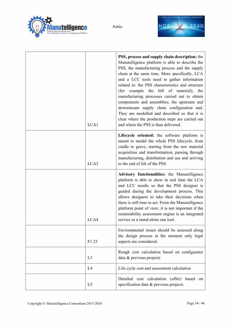
LCA1
PSS, process and supply chain description: the Manutelligence platform is able to describe the PSS, the manufacturing process and the supply chain at the same time. More specifically, LCA and a LCC tools need to gather information related to: the PSS characteristics and structure (for example the bill of material); the manufacturing processes carried out to obtain components and assemblies; the upstream and downstream supply chain configuration and. They are modelled and described so that it is clear where the production steps are carried out and where the PSS is than delivered.
LCA2
Lifecycle oriented: the software platform is meant to model the whole PSS lifecycle, from cradle to grave, starting from the raw material acquisition and transformation, passing through manufacturing, distribution and use and arriving to the end of life of the PSS.
LCA4
Advisory functionalities: the Manutelligence platform is able to show in real time the LCA and LCC results so that the PSS designer is guided during the development process. This allows designers to take their decisions when there is still time to act. From the Manutelligence platform point of view, it is not important if the sustainability assessment engine is an integrated service or a stand-alone one tool.
F1.23
Environmental issues should be assessed along the design process at the moment only legal aspects are considered.
L3
Rough cost calculation based on configurator data & previous projects
L4 Life cycle cost and assessment calculation
L5
Detailed cost calculation (offer) based on specification data & previous projects
Public
Copyright � Manutelligence Consortium 2015-2018 Page 35 / 46
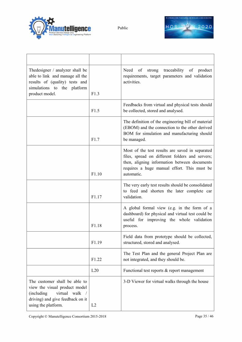
Thedesigner / analyzer shall be able to link and manage all the results of (quality) tests and simulations to the platform product model. F1.3
Need of strong traceability of product requirements, target parameters and validation activities.
F1.5
Feedbacks from virtual and physical tests should be collected, stored and analysed.
F1.7
The definition of the engineering bill of material (EBOM) and the connection to the other derived BOM for simulation and manufacturing should be managed.
F1.10
Most of the test results are saved in separated files, spread on different folders and servers; then, aligning information between documents requires a huge manual effort. This must be automatic.
F1.17
The very early test results should be consolidated to feed and shorten the later complete car validation.
F1.18
A global formal view (e.g. in the form of a dashboard) for physical and virtual test could be useful for improving the whole validation process.
F1.19
Field data from prototype should be collected, structured, stored and analysed.
F1.22
The Test Plan and the general Project Plan are not integrated, and they should be.
L20 Functional test reports & report management
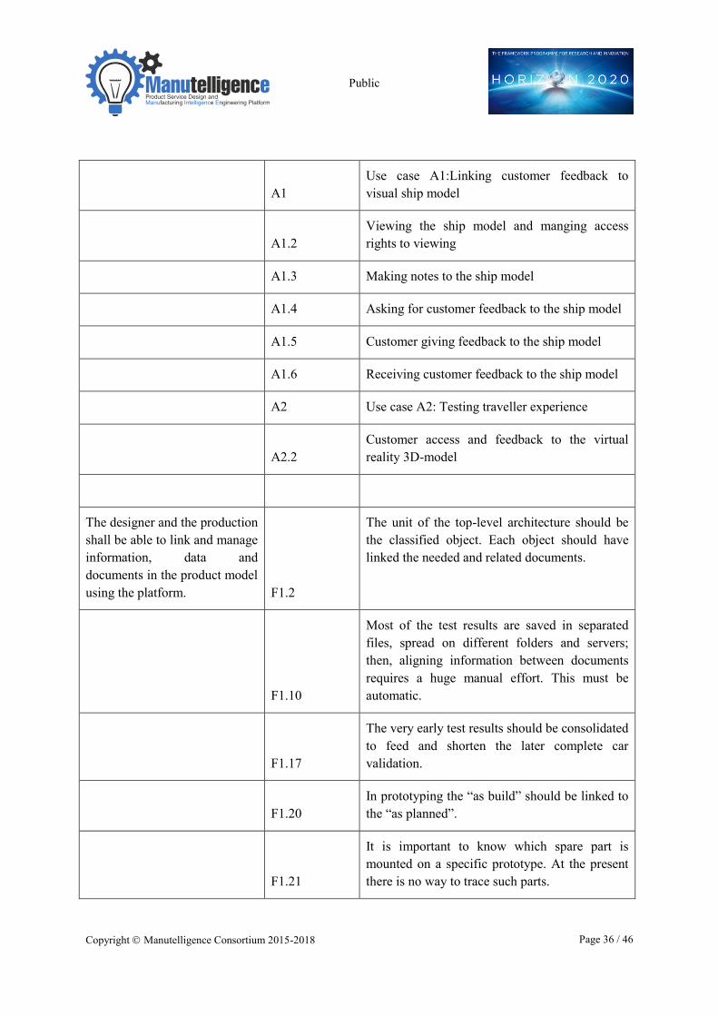
The customer shall be able to view the visual product model (including virtual walk / driving) and give feedback on it using the platform. L2
3-D Viewer for virtual walks through the house
Public
Copyright � Manutelligence Consortium 2015-2018 Page 36 / 46
A1
Use case A1:Linking customer feedback to visual ship model
A1.2
Viewing the ship model and manging access rights to viewing
A1.3 Making notes to the ship model
A1.4 Asking for customer feedback to the ship model
A1.5 Customer giving feedback to the ship model
A1.6 Receiving customer feedback to the ship model
A2 Use case A2: Testing traveller experience
A2.2
Customer access and feedback to the virtual reality 3D-model
The designer and the production shall be able to link and manage information, data and documents in the product model using the platform. F1.2
The unit of the top-level architecture should be the classified object. Each object should have linked the needed and related documents.
F1.10
Most of the test results are saved in separated files, spread on different folders and servers; then, aligning information between documents requires a huge manual effort. This must be automatic.
F1.17
The very early test results should be consolidated to feed and shorten the later complete car validation.
F1.20
In prototyping the “as build” should be linked to the “as planned”.
F1.21
It is important to know which spare part is mounted on a specific prototype. At the present there is no way to trace such parts.
Public
Copyright � Manutelligence Consortium 2015-2018 Page 37 / 46
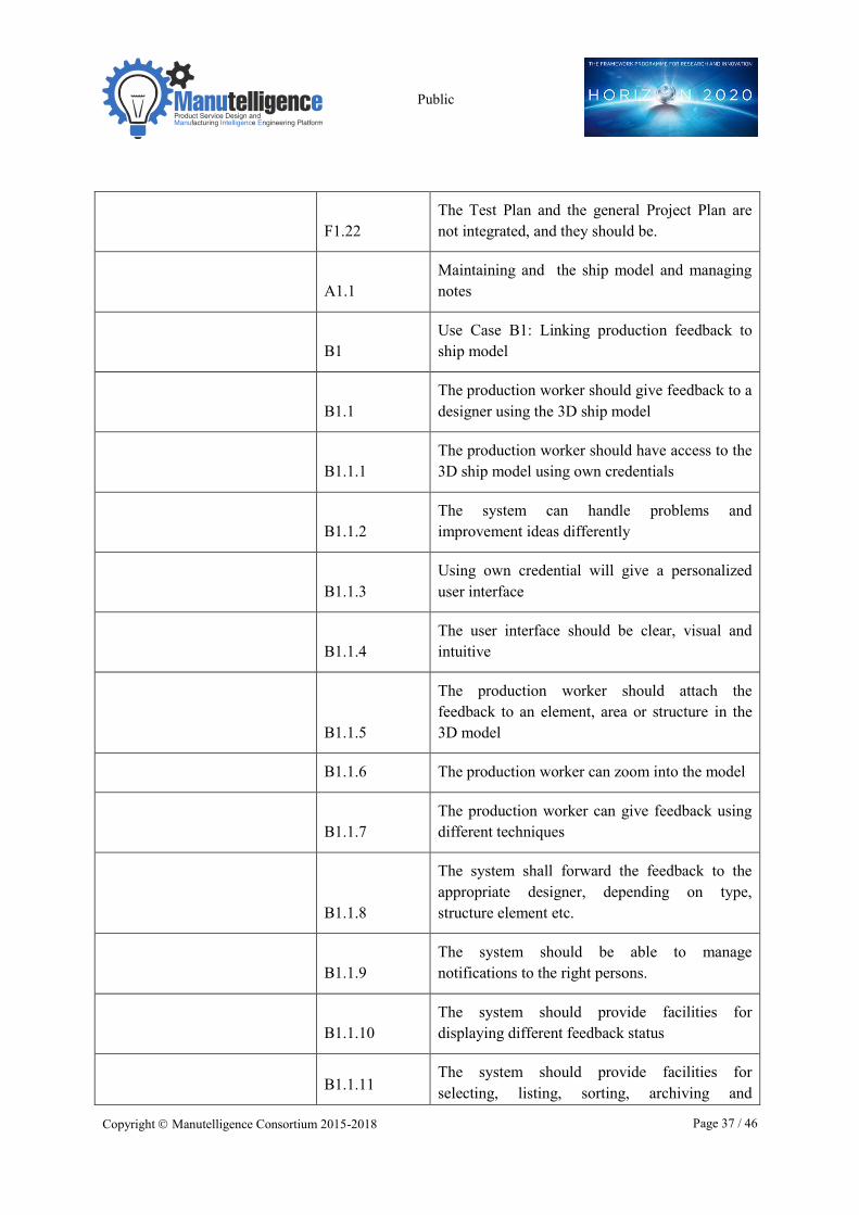
F1.22
The Test Plan and the general Project Plan are not integrated, and they should be.
A1.1
Maintaining and the ship model and managing notes
B1
Use Case B1: Linking production feedback to ship model
B1.1
The production worker should give feedback to a designer using the 3D ship model
B1.1.1
The production worker should have access to the 3D ship model using own credentials
B1.1.2
The system can handle problems and improvement ideas differently
B1.1.3
Using own credential will give a personalized user interface
B1.1.4
The user interface should be clear, visual and intuitive
B1.1.5
The production worker should attach the feedback to an element, area or structure in the 3D model
B1.1.6 The production worker can zoom into the model
B1.1.7
The production worker can give feedback using different techniques
B1.1.8
The system shall forward the feedback to the appropriate designer, depending on type, structure element etc.
B1.1.9
The system should be able to manage notifications to the right persons.
B1.1.10
The system should provide facilities for displaying different feedback status
B1.1.11
The system should provide facilities for selecting, listing, sorting, archiving and
Public
Copyright � Manutelligence Consortium 2015-2018 Page 38 / 46
managing feedback issues
B1.1.12
The system should be linked to rewarding system for improvement ideas
B2.1.5 The 3D model should contain links to BOM
B2.1.6
The 3D model should contain links to scheduling information
C1
Use case C1: Guiding designer to fit the construction method
C1.1
Management of construction method and related models/documents
C1.1.1
Manage area types, construction method and their characteristics (new, view, modify, save)
C1.1.2
Manage guideline categories based on standardized design and material phases (new, view, modify, save)
C1.1.3
Manage guidelines & “standard” drawings (for manufacturing and installation
C1.1.5 Link to material management
C1.1.6 Manage construction method “library”
C1.2
Training support and review of the construction method approach
C1.1.4
Manage manufacturing/ outfitting schedule library
D1.3
The model should be cleaned from all information to building and assembly
D1.4
The model should have links from details to drawing documents
Serving production through model
Public
Copyright � Manutelligence Consortium 2015-2018 Page 39 / 46
The production personnel shall be able to use the product model on the platform to support and monitor production, installation and to give feedback for the design.
F1.14
The engine department is weak integrated with the rest of the enterprise; the platform should reduce this gap.
L9 Supplier product data base (catalogues)
L13 Production designs & design mgmt.
L14 Production cost tracking
L18 Production site status reporting
B1
Use Case B1: Linking production feedback to ship model
B1.1
The production worker should give feedback to a designer using the 3D ship model
B1.1.2
The system can handle problems and improvement ideas differently
B1.1.5
The production worker should attach the feedback to an element, area or structure in the 3D model
B1.1.6 The production worker can zoom into the model
B1.1.7
The production worker can give feedback using different techniques
B1.1.8
The system shall forward the feedback to the appropriate designer, depending on type, structure element etc.
B1.1.9
The system should be able to manage notifications to the right persons.
Public
Copyright � Manutelligence Consortium 2015-2018 Page 40 / 46
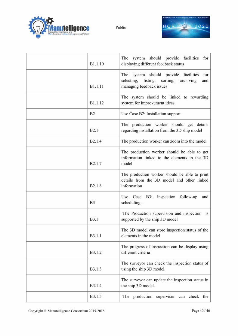
B1.1.10
The system should provide facilities for displaying different feedback status
B1.1.11
The system should provide facilities for selecting, listing, sorting, archiving and managing feedback issues
B1.1.12
The system should be linked to rewarding system for improvement ideas
B2 Use Case B2: Installation support .
B2.1
The production worker should get details regarding installation from the 3D ship model
B2.1.4 The production worker can zoom into the model
B2.1.7
The production worker should be able to get information linked to the elements in the 3D model
B2.1.8
The production worker should be able to print details from the 3D model and other linked information
B3
Use Case B3: Inspection follow-up and scheduling .
B3.1
The Production supervision and inspection is supported by the ship 3D model
B3.1.1
The 3D model can store inspection status of the elements in the model
B3.1.2
The progress of inspection can be display using different criteria
B3.1.3
The surveyor can check the inspection status of using the ship 3D model.
B3.1.4
The surveyor can update the inspection status in the ship 3D model.
B3.1.5 The production supervisor can check the
Public
Copyright � Manutelligence Consortium 2015-2018 Page 41 / 46
inspection status of using the ship 3D model.
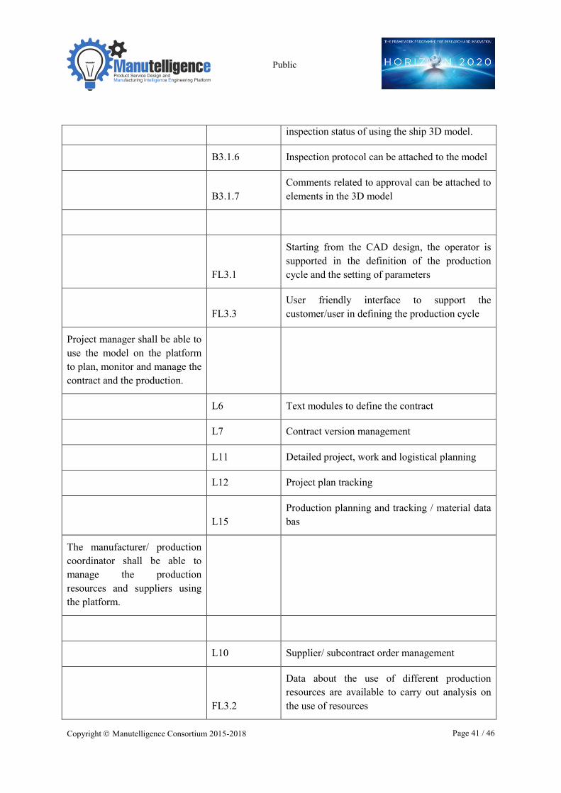
B3.1.6 Inspection protocol can be attached to the model
B3.1.7
Comments related to approval can be attached to elements in the 3D model
FL3.1
Starting from the CAD design, the operator is supported in the definition of the production cycle and the setting of parameters
FL3.3
User friendly interface to support the customer/user in defining the production cycle
Project manager shall be able to use the model on the platform to plan, monitor and manage the contract and the production.
L6 Text modules to define the contract
L7 Contract version management
L11 Detailed project, work and logistical planning
L12 Project plan tracking
L15
Production planning and tracking / material data bas
The manufacturer/ production coordinator shall be able to manage the production resources and suppliers using the platform.
L10 Supplier/ subcontract order management
FL3.2
Data about the use of different production resources are available to carry out analysis on the use of resources
Public
Copyright � Manutelligence Consortium 2015-2018 Page 42 / 46
The production / quality management shall be able to manage and follow the quality and failure data on the platform.
L16
Quality (failure) measurements, reports & failure analysis mgmt.
L17 Failure fixing knowledge base
Model for operation & user services
The user/ service provider shall be able to monitor the behaviour of the product using the product model and linked sensors with access to the platform.
L22
Sensor data mgmt. based on integrated sensors (humidity, temperature, noise, motion, etc.)
D1
Use case D1: Intelligent ship model use in ship operation and maintenance
FL4.1
Sensors embedded in smart object send data to the Manutelligence platform
FL4.2
Users of smart objects are allowed to analyse data about the use of the product itself through a reserved access to the Manutelligence platform
The service provider shall be able to manage the services and their data on the platform.
L21
Quality reports & failure analysis based on warranty info
L23 Repair management & repair data management
L24
Pay per use service mgmt. (actuator control) & service data management.
Public
Copyright � Manutelligence Consortium 2015-2018 Page 43 / 46
L25
Facility data mgmt. (installation drawings, installed item lists, guarantee terms)
FL4.3
Data from objects in use are statistically analysed to support the design of new products
Non-functional requirements (including sharing information)
All information shall be managed and embedded in a common platform which is applicable for different industrial sectors
F1.6
The data held in Excel, Word and Power Point file should be embedded and managed in the platform.
F1.13
A common platform is needed for centralise the activities.
F1.14
The engine department is weak integrated with the rest of the enterprise; the platform should reduce this gap.
LCA3
Applicable to different industrial sectors: even though validated into the project industrial use cases, the software is meant to be general purpose and developed in order to cover many different industrial sectors.
LCA8
Ability to manage background and foreground data: the Manutelligence platform can manage and store both data directly coming from the user and data contained in private or public database (e.g. data concerning the raw material costs or Life Cycle Impact Assessment data).
The platform shall provide user management and allow access to stakeholders according their
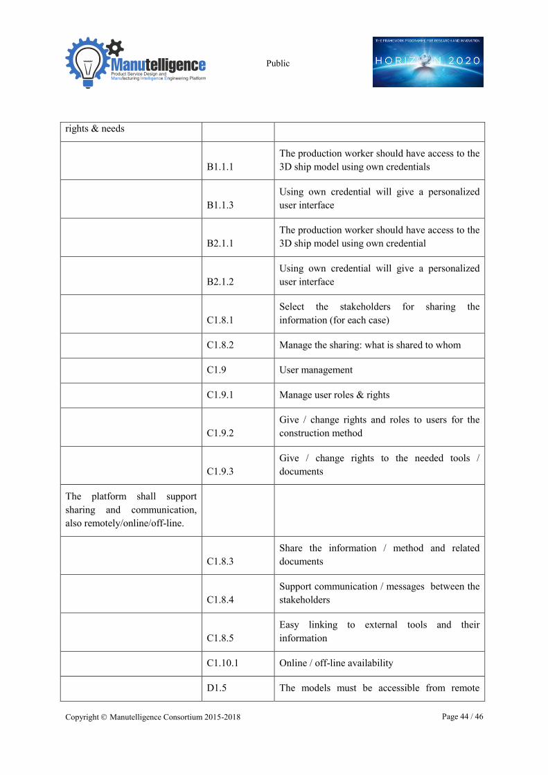
Public
Copyright � Manutelligence Consortium 2015-2018 Page 44 / 46
rights & needs
B1.1.1
The production worker should have access to the 3D ship model using own credentials
B1.1.3
Using own credential will give a personalized user interface
B2.1.1
The production worker should have access to the 3D ship model using own credential
B2.1.2
Using own credential will give a personalized user interface
C1.8.1
Select the stakeholders for sharing the information (for each case)
C1.8.2 Manage the sharing: what is shared to whom
C1.9 User management
C1.9.1 Manage user roles & rights
C1.9.2
Give / change rights and roles to users for the construction method
C1.9.3
Give / change rights to the needed tools / documents
The platform shall support sharing and communication, also remotely/online/off-line.
C1.8.3
Share the information / method and related documents
C1.8.4
Support communication / messages between the stakeholders
C1.8.5
Easy linking to external tools and their information
C1.10.1 Online / off-line availability
D1.5 The models must be accessible from remote
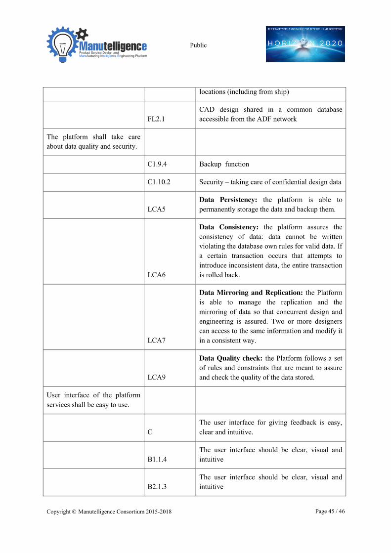
Public
Copyright � Manutelligence Consortium 2015-2018 Page 45 / 46
locations (including from ship)
FL2.1
CAD design shared in a common database accessible from the ADF network
The platform shall take care about data quality and security.
C1.9.4 Backup function
C1.10.2 Security – taking care of confidential design data
LCA5
Data Persistency: the platform is able to permanently storage the data and backup them.
LCA6
Data Consistency: the platform assures the consistency of data: data cannot be written violating the database own rules for valid data. If a certain transaction occurs that attempts to introduce inconsistent data, the entire transaction is rolled back.
LCA7
Data Mirroring and Replication: the Platform is able to manage the replication and the mirroring of data so that concurrent design and engineering is assured. Two or more designers can access to the same information and modify it in a consistent way.
LCA9
Data Quality check: the Platform follows a set of rules and constraints that are meant to assure and check the quality of the data stored.
User interface of the platform services shall be easy to use.
C
The user interface for giving feedback is easy, clear and intuitive.
B1.1.4
The user interface should be clear, visual and intuitive
B2.1.3
The user interface should be clear, visual and intuitive
Public
Copyright � Manutelligence Consortium 2015-2018 Page 46 / 46
B3.1.8
The user interface should be clear, visual and intuitive
C1.2.4 Online guidance?
D1.6
The model users must have easy to use tool to update the model