D1.2 Initial TagItSmart! Reference Architecture and API ... · 1.1 FIWARE ... 2.2.1 Use case...
60
TagItSmart! Smart Tags driven service platform for enabling ecosystems of connected objects Grant agreement 688061 D1.2 Initial TagItSmart! Reference Architecture and API description Deliverable ID: D 1.2 Deliverable Title: Initial TagItSmart! Reference Architecture and API description Revision #: 1.0 Dissemination Level: Public Responsible beneficiary: EVT Contributing beneficiaries: All Contractual date of delivery: 31.12.2016 Actual submission date: 23.01.2017 Start Date of the Project: 1 January 2016 Duration: 36 Months Ref. Ares(2017)357802 - 23/01/2017
Transcript of D1.2 Initial TagItSmart! Reference Architecture and API ... · 1.1 FIWARE ... 2.2.1 Use case...
TagItSmart!
Smart Tags driven service platform for enabling ecosystems of connected objects
Grant agreement 688061
D1.2 Initial TagItSmart! Reference Architecture and API description
Deliverable ID: D 1.2
Deliverable Title: Initial TagItSmart! Reference Architecture and API description
Revision #: 1.0 Dissemination Level: Public Responsible beneficiary: EVT Contributing beneficiaries: All Contractual date of delivery: 31.12.2016 Actual submission date: 23.01.2017
Start Date of the Project: 1 January 2016 Duration: 36 Months
Ref. Ares(2017)357802 - 23/01/2017
Contents
Introduction ......................................................................................................................... 5
Section 1 - IoT Reference Architectures ........................................................................ 6
1.1 FIWARE ................................................................................................................ 6
1.2 SocIoTal ................................................................................................................ 6
1.3 IoT-A ..................................................................................................................... 7
Section 2 - Use cases requirements towards functional components ........................ 9
2.1 Digital Products ................................................................................................... 9 2.1.1 Use case overview ............................................................................................. 9 2.1.2 Use case requirements .....................................................................................10
2.2 Lifecycle Management/Recycling ......................................................................11 2.2.1 Use case overview ............................................................................................11 2.2.2 Use case requirements .....................................................................................12
2.3 Brand Protection .................................................................................................15 2.3.1 Use case overview ............................................................................................15 2.3.2 Use case requirements .....................................................................................15
2.4 Dynamic Pricing ..................................................................................................17 2.4.1 Use case overview ............................................................................................17 2.4.2 Use case requirements .....................................................................................17
2.5 Home Services ....................................................................................................19 2.5.1 Use case overview ............................................................................................19 2.5.2 Use case requirements .....................................................................................21
Section 3 - TagItSmart IoT Platform Functional Architecture .....................................23
3.1 Identified Components and Services ................................................................23 3.1.1 Service Management ........................................................................................24 3.1.2 Virtual Entities ...................................................................................................25 3.1.3 SmartTags ........................................................................................................26 3.1.4 User Management and Security ........................................................................27 3.1.5 Domain Management ........................................................................................28 3.1.6 Utility Services ..................................................................................................29 3.1.7 Application Tools ...............................................................................................29
3.2 Functional View ...................................................................................................30 3.2.1 IoT-A functional mapping of TagItSmart ............................................................31 3.2.2 FIWARE functional mapping of TagItSmart .......................................................32
3.3 Information Views ...............................................................................................34 3.3.1 Template Resolution .........................................................................................36 3.3.2 SmartTag Creation and Printing ........................................................................36 3.3.3 SmartTag FC-Scan / Push Information to Services / Push Information to Users39 3.3.4 Push Information to Services/Users to actuate on a device ...............................43
3.4 Data Models .........................................................................................................47 3.4.1 Use Case Data Models .....................................................................................47 3.4.2 Unified Data Model and IoT-A Mapping .............................................................54

Section 4 - TagItSmart Components Integration Strategies........................................55
Section 5 - Conclusions and Future Work ....................................................................59
Section 6 - References ...................................................................................................60
Figures Figure 1.- Sociotal architecture mapped to IoT-A................................................................... 7 Figure 2.- IoT-A architecture .................................................................................................. 8 Figure 3.- Digital Products use case features ........................................................................ 9 Figure 4.- Digital Products use case conceptual flow ............................................................10 Figure 5.- Lifecycle Management/Recycling use case conceptual flow .................................12 Figure 6.- Brand protection use case conceptual flow ..........................................................15 Figure 7.- Dynamic pricing use case conceptual flow ...........................................................17 Figure 8.- Home Services Use Case conceptual flow ...........................................................20 Figure 9.- Service Management Component Group .............................................................25 Figure 10.- Virtual Entities Component Group ......................................................................26 Figure 11.- Smart Tags Component Group ...........................................................................27 Figure 12.- User Management and Security Component Group ...........................................28 Figure 13.- Domain Management Component Group ...........................................................28 Figure 14.- Utility Services Component Group ......................................................................29 Figure 15.- Application Tools Component Group ..................................................................30 Figure 16.- TagItSmart Platform Functional Architecture ......................................................30 Figure 17.- TagItSmart Functional View (IoT-A Mapping) .....................................................31 Figure 18.- TagItSmart SmartTags related main flows and variations ...................................35 Figure 19.- Template Resolution (Product VE Creation) .......................................................37 Figure 20.- SmartTag Creation and Printing (Basic Identity Provisioning) .............................38 Figure 21.- SmartTag Creation and Printing (Identity Provisioning based on a PE) ..............40 Figure 22 – SmartTag Creation and Printing (Identity Provisioning based on a PE and Data Integration) ...........................................................................................................................41 Figure 23.- SmartTag FC-Scan (Context and Notifications) ..................................................42 Figure 24.- SmartTag FC-Scan (Context and Notification with External Services) ................44 Figure 25 – SmartTag FC-Scan (Complex Rules) ................................................................45 Figure 26 – Push Information from/to a device (Complex rules) ...........................................46 Figure 27.- Digital Product Simplified Data Model .................................................................48 Figure 28.- Lifecycle Management Simplified Data Model ....................................................49 Figure 29.- Brand Protection Simplified Data Model .............................................................50 Figure 30.- Dynamic Pricing Simplified Data Model ..............................................................51 Figure 31.- Home Services Simplified Data Model ................................................................53 Figure 32.- TagItSmart Data Model Overview and IoT-A Mapping ........................................54
Tables Table 1.- Digital Products Use Case Requirements Summary ..............................................10 Table 2.- Lifecycle Management /Recycling Use Case Requirements Summary ..................12 Table 3.- Brand Protection Use Case Requirements Summary ............................................15 Table 4.- Dynamic Pricing Use Case Requirements Summary .............................................18 Table 5.- Home Services Use Case Requirements Summary...............................................21 Table 6.- Service Management Components Description .....................................................24
Table 7.- Virtual Entities Components Description ................................................................25 Table 8.- Smart Tags Components Description ....................................................................26 Table 9.- User Management and Security Components Description .....................................27 Table 10.- Domain Management Components Description ...................................................28 Table 11.- Utility Services Components Description .............................................................29 Table 12.- Application Tools Components Description .........................................................29 Table 13.- List of FIWARE technology that maps to the TagItSmart functional blocks ..........33 Table 14.- Digital Product Data Model Entities .....................................................................47 Table 15.- Lifecycle Management Data Model Entities .........................................................48 Table 16.- Brand Protection Data Model Entities ..................................................................49 Table 17.- Dynamic Pricing Data Model Entities ...................................................................50 Table 18.- Home Services Data Model Entities ....................................................................52 Table 19.- Integration Strategies ..........................................................................................55 Table 20.- Preliminary API Design guidelines .......................................................................56
Page 5/60
Introduction This document is deliverable D1.2 Initial TagItSmart! Reference Architecture and API description that presents the work done in work package WP 1 (Tasks 1.2 and 1.3) in the TagItSmart project during the first year. Being the project intensively use case driven, we took the input from D1.1 and workshopped with the different use case partners to define more detailed technical requirements to outline the components that are needed to implement TagItSmart. The approach followed for the architecture design was based in the idea that we are not building yet another IoT platform from scratch, but rather define a set of reusable components that can be integrated in existing systems that will enable the use and governance of SmartTags in different platforms. For this, we have analysed and reused as a starting point guidelines from other state-of-the-art reference architectures to define a common operational framework and promote reusability. The architecture of the solution and the different components will be designed iteratively, being this deliverable the first design, that will be used in the first stages of the validation (as defined in D5.1 Infrastructure for trials and pilots for the lab tests). Feedback or technical issues and improvements collected throughout the different validation stages, as well as during the Open Calls will shape the architecture, the final version of which will be reported consequently in deliverable D1.3 Final TagItSmart! Reference Architecture and API description scheduled for month 24. The deliverable is organised as follows:
Section 1 focuses on state-of-the-art IoT reference architectures and the rationale on the connection to TagItSmart if applicable.
Section 2 gives an overview of the different use cases and elaborates on the technical requirements to later define the architectural components needed to implement the architecture.
Section 3 focuses on the high-level architecture and the definition of the different technical components and main interactions. It considers the technical requirements from each use case and presents the functional components needed (Section 3.1), the functional view of the architecture, as well as how it maps to selected state-of-the-art reference architectures (Section 3.2) and explores the most significant information flows and the data models needed based on the aforementioned architecture (Section 3.3 and Section 3.4).
Section 4 outlines the proposed strategies on how to integrate TagItSmart components in other platforms and the first guidelines of a set of APIs for the main components.
Finally, in Section 5 we present the conclusions and future work on the architectural work.
Page 6/60
Section 1 - IoT Reference Architectures Extensive work has already been done attempting to define IoT Architectures. Our approach for TagItSmart is focused not only on learning from them, but also reusing existing concepts and platforms, providing extensions or defining specific components following the guidelines exposed in state-of-the-art solutions. In the following subsections, we briefly discuss some aspects of the most recent publicly available IoT reference architectures and how they relate to TagItSmart. 1.1 FIWARE
In this section the FIWARE platform is described from the perspective of TagItSmart requirements, providing more details about its possible employment in the project. FIWARE is an innovative, open cloud-based infrastructure for cost-effective creation and delivery of Future Internet applications and services. In few words, it specifies an overall Reference Architecture [1] divided in several sub-reference architectures:
Cloud Hosting
Data/Context Management
IoT Services Enablement
Applications/Services Ecosystem and Delivery Framework
Security
Interface to Networks and Devices (I2ND) These architectures are composed by different building blocks that define the APIs and the functionalities belonging to every sub-architecture. These components are known as General Enablers (GE), so the Reference Architecture associated to each FIWARE chapter can be instantiated into a concrete architecture by means of selecting and integrating products implementing the corresponding FIWARE GEs. Two of the main envisioned features of the TagItSmart! platform are openness and
interoperability. As the goal is to provide a platform built using a set of open source components
from existing solutions the licence that each GE has should be analysed to provide distinction
between fully open sourced components and components that offer only open APIs. This will
allow for the project to expose a set of open interfaces and functional modules for the IoT
platforms interoperability. In this scope, FIWARE was analysed as there is already an existing
ecosystem around it and having in mind the technology it provides and the specified RESTful
interfaces.
1.2 SocIoTal
The Sociotal platform [2] is built around a central component, the Context Manager that holds the database with the contextual information. All the components and enablers will interact with the Context Manager to access data in a confidential way. The Context Manager database is fed with data collected by the sensors in the physical world and sent to the cloud via sensinact Gateway that ensures the interoperability of the communications and the protocols.
Page 7/60
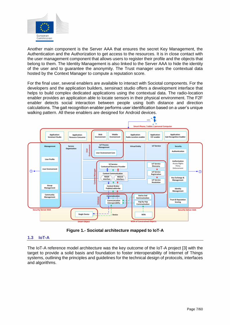
Another main component is the Server AAA that ensures the secret Key Management, the Authentication and the Authorization to get access to the resources. It is in close contact with the user management component that allows users to register their profile and the objects that belong to them. The Identity Management is also linked to the Server AAA to hide the identity of the user and to guarantee the anonymity. The Trust manager uses the contextual data hosted by the Context Manager to compute a reputation score. For the final user, several enablers are available to interact with Sociotal components. For the developers and the application builders, sensinact studio offers a development interface that helps to build complex dedicated applications using the contextual data. The radio-location enabler provides an application able to locate sensors in their physical environment. The F2F enabler detects social interaction between people using both distance and direction calculations. The gait recognition enabler performs user identification based on a user’s unique walking pattern. All these enablers are designed for Android devices.
Figure 1.- Sociotal architecture mapped to IoT-A
1.3 IoT-A
The IoT-A reference model architecture was the key outcome of the IoT-A project [3] with the target to provide a solid basis and foundation to foster interoperability of Internet of Things systems, outlining the principles and guidelines for the technical design of protocols, interfaces and algorithms.
Page 8/60
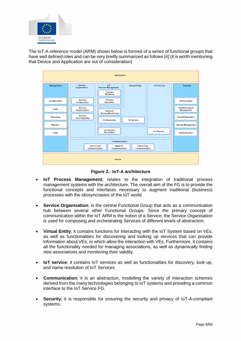
The IoT-A reference model (ARM) shown below is formed of a series of functional groups that have well defined roles and can be very briefly summarized as follows [4] (it is worth mentioning that Device and Application are out of consideration)
Figure 2.- IoT-A architecture
IoT Process Management; relates to the integration of traditional process management systems with the architecture. The overall aim of the FG is to provide the functional concepts and interfaces necessary to augment traditional (business) processes with the idiosyncrasies of the IoT world.
Service Organisation; is the central Functional Group that acts as a communication hub between several other Functional Groups. Since the primary concept of communication within the IoT ARM is the notion of a Service, the Service Organisation is used for composing and orchestrating Services of different levels of abstraction.
Virtual Entity; it contains functions for interacting with the IoT System based on VEs, as well as functionalities for discovering and looking up services that can provide information about VEs, or which allow the interaction with VEs. Furthermore, it contains all the functionality needed for managing associations, as well as dynamically finding new associations and monitoring their validity.
IoT service; it contains IoT services as well as functionalities for discovery, look-up, and name resolution of IoT Services
Communication; it is an abstraction, modelling the variety of interaction schemes derived from the many technologies belonging to IoT systems and providing a common interface to the IoT Service FG.
Security; it is responsible for ensuring the security and privacy of IoT-A-compliant systems.
Page 9/60
Management; it combines all functionalities that are needed to govern an IoT system.
IoT-A provides a good framework to define an IoT architecture and proposes a common vocabulary to refer to the different components and capabilities.
Section 2 - Use cases requirements towards functional components Deliverable D1.1 Use Case Descriptions, Requirements and Market Analysis compiled the descriptions of the use cases and the functional requirements that were envisioned for each of them. To extract and define a common architecture to enable the TagItSmart specific features, we now analyse in more depth the technical implications. For each use case, we include a brief overview, to set up the context to then aggregate the requirements from the capabilities point of view that will enable us to define components and their expected behaviour. 2.1 Digital Products
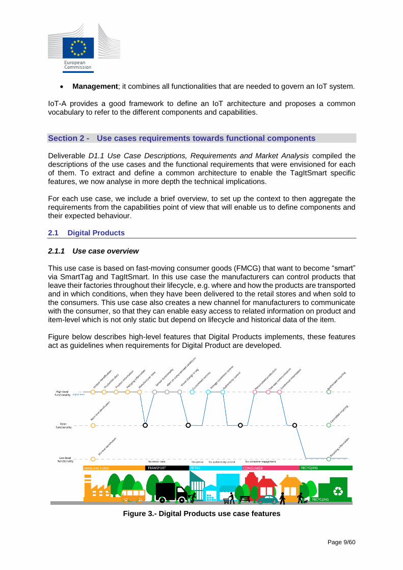
2.1.1 Use case overview This use case is based on fast-moving consumer goods (FMCG) that want to become “smart” via SmartTag and TagItSmart. In this use case the manufacturers can control products that leave their factories throughout their lifecycle, e.g. where and how the products are transported and in which conditions, when they have been delivered to the retail stores and when sold to the consumers. This use case also creates a new channel for manufacturers to communicate with the consumer, so that they can enable easy access to related information on product and item-level which is not only static but depend on lifecycle and historical data of the item. Figure below describes high-level features that Digital Products implements, these features act as guidelines when requirements for Digital Product are developed.
Figure 3.- Digital Products use case features
Page 10/60
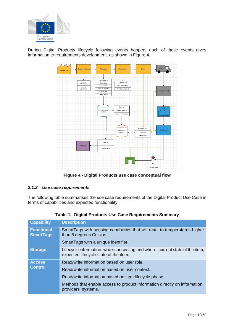
During Digital Products lifecycle following events happen, each of these events gives information to requirements development, as shown in Figure 4.
Figure 4.- Digital Products use case conceptual flow
2.1.2 Use case requirements The following table summarises the use case requirements of the Digital Product Use Case in terms of capabilities and expected functionality.
Table 1.- Digital Products Use Case Requirements Summary
Capability Description
Functional SmartTags
SmartTags with sensing capabilities that will react to temperatures higher than 8 degrees Celsius.
SmartTags with a unique identifier.
Storage Lifecycle information: who scanned tag and where, current state of the item, expected lifecycle state of the item.
Access Control
Read/write information based on user role.
Read/write information based on user context.
Read/write information based on item lifecycle phase.
Methods that enable access to product information directly on information providers’ systems.
Page 11/60
Capability Description
SmartTag Scanner
Industrial level scanner that can scan SmartTags at manufacturing line.
Hand-held scanner that can scan SmartTags during transport event.
Hand-held scanner that can scan SmartTags while in retail store.
Industrial scanner that can scan SmartTags on POS.
Mobile device based scanner that can scan SmartTags.
SmartTag Printer
Printing of labels that have unique SmartTags printed on them. These SmartTags have static, functional, sensor and authenticity functions.
External Services
Interconnection between manufacturers systems to TagItSmart system to register items.
Notifications Register for product notifications and receive notifications.
Product updates
Providing information to manufacturer / retail / recycling.
Product purchase
Ordering of customized products from manufacturer.
Social Media connections
Connecting to social media when scanning item to share the experience.
Event Management
Registration of scan event into TagItSmart system.
Recycling Service
Information about recycling of an item.
2.2 Lifecycle Management/Recycling
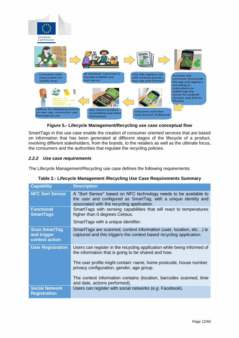
2.2.1 Use case overview The lifecycle management/recycling use case is built around the concept of consumers buying products in the supermarket and engaging with them in different ways, focusing on the recyclability of the product, creating an ecosystem where consumers are provided with information about how to recycle a product based on contextual information (location, local regulations) and product recyclability (materials); information that is linked to the SmartTags on the products.
Page 12/60
Figure 5.- Lifecycle Management/Recycling use case conceptual flow
SmartTags in this use case enable the creation of consumer oriented services that are based on information that has been generated at different stages of the lifecycle of a product, involving different stakeholders, from the brands, to the retailers as well as the ultimate focus, the consumers and the authorities that regulate the recycling policies. 2.2.2 Use case requirements The Lifecycle Management/Recycling use case defines the following requirements:
Table 2.- Lifecycle Management /Recycling Use Case Requirements Summary
Capability Description
NFC Sort Sensor A “Sort Sensor” based on NFC technology needs to be available to the user and configured as SmartTag, with a unique identity and associated with the recycling application.
Functional SmartTags
SmartTags with sensing capabilities that will react to temperatures higher than 0 degrees Celsius.
SmartTags with a unique identifier.
Scan SmartTag and trigger context action
SmartTags are scanned, context information (user, location, etc…) is captured and this triggers the context based recycling application.
User Registration Users can register in the recycling application while being informed of the information that is going to be shared and how. The user profile might contain: name, home postcode, house number, privacy configuration, gender, age group. The context information contains (location, barcodes scanned, time and date, actions performed).
Social Network Registration
Users can register with social networks (e.g. Facebook).
Page 13/60
Capability Description
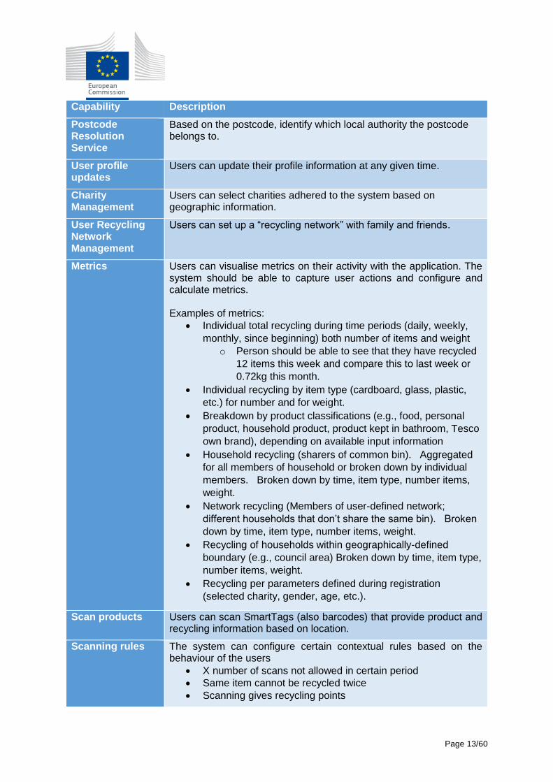
Postcode Resolution Service
Based on the postcode, identify which local authority the postcode belongs to.
User profile updates
Users can update their profile information at any given time.
Charity Management
Users can select charities adhered to the system based on geographic information.
User Recycling Network Management
Users can set up a “recycling network” with family and friends.
Metrics Users can visualise metrics on their activity with the application. The system should be able to capture user actions and configure and calculate metrics. Examples of metrics:
Individual total recycling during time periods (daily, weekly,
monthly, since beginning) both number of items and weight
o Person should be able to see that they have recycled
12 items this week and compare this to last week or
0.72kg this month.
Individual recycling by item type (cardboard, glass, plastic,
etc.) for number and for weight.
Breakdown by product classifications (e.g., food, personal
product, household product, product kept in bathroom, Tesco
own brand), depending on available input information
Household recycling (sharers of common bin). Aggregated
for all members of household or broken down by individual
members. Broken down by time, item type, number items,
weight.
Network recycling (Members of user-defined network;
different households that don’t share the same bin). Broken
down by time, item type, number items, weight.
Recycling of households within geographically-defined
boundary (e.g., council area) Broken down by time, item type,
number items, weight.
Recycling per parameters defined during registration
(selected charity, gender, age, etc.).
Scan products Users can scan SmartTags (also barcodes) that provide product and recycling information based on location.
Scanning rules The system can configure certain contextual rules based on the behaviour of the users
X number of scans not allowed in certain period
Same item cannot be recycled twice
Scanning gives recycling points
Page 14/60
Capability Description
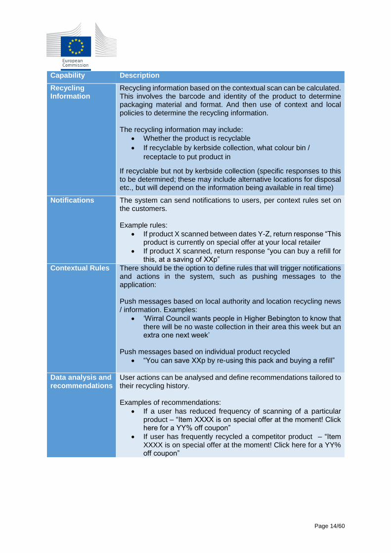
Recycling Information
Recycling information based on the contextual scan can be calculated. This involves the barcode and identity of the product to determine packaging material and format. And then use of context and local policies to determine the recycling information. The recycling information may include:
Whether the product is recyclable
If recyclable by kerbside collection, what colour bin /
receptacle to put product in
If recyclable but not by kerbside collection (specific responses to this to be determined; these may include alternative locations for disposal etc., but will depend on the information being available in real time)
Notifications The system can send notifications to users, per context rules set on the customers. Example rules:
If product X scanned between dates Y-Z, return response “This product is currently on special offer at your local retailer
If product X scanned, return response “you can buy a refill for this, at a saving of XXp”
Contextual Rules There should be the option to define rules that will trigger notifications and actions in the system, such as pushing messages to the application: Push messages based on local authority and location recycling news / information. Examples:
‘Wirral Council wants people in Higher Bebington to know that there will be no waste collection in their area this week but an extra one next week’
Push messages based on individual product recycled
“You can save XXp by re-using this pack and buying a refill”
Data analysis and recommendations
User actions can be analysed and define recommendations tailored to their recycling history. Examples of recommendations:
If a user has reduced frequency of scanning of a particular product – “Item XXXX is on special offer at the moment! Click here for a YY% off coupon”
If user has frequently recycled a competitor product – “Item XXXX is on special offer at the moment! Click here for a YY% off coupon”
Page 15/60
2.3 Brand Protection
2.3.1 Use case overview
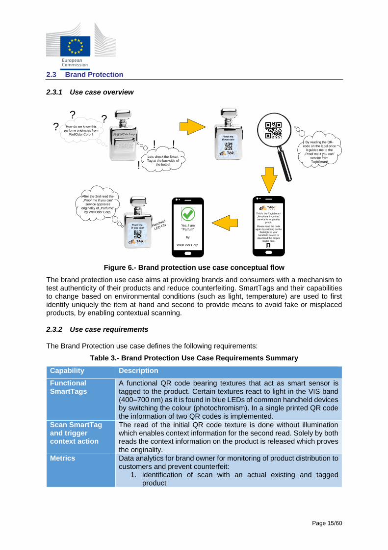
Figure 6.- Brand protection use case conceptual flow
The brand protection use case aims at providing brands and consumers with a mechanism to test authenticity of their products and reduce counterfeiting. SmartTags and their capabilities to change based on environmental conditions (such as light, temperature) are used to first identify uniquely the item at hand and second to provide means to avoid fake or misplaced products, by enabling contextual scanning. 2.3.2 Use case requirements The Brand Protection use case defines the following requirements:
Table 3.- Brand Protection Use Case Requirements Summary
Capability Description
Functional SmartTags
A functional QR code bearing textures that act as smart sensor is tagged to the product. Certain textures react to light in the VIS band (400–700 nm) as it is found in blue LEDs of common handheld devices by switching the colour (photochromism). In a single printed QR code the information of two QR codes is implemented.
Scan SmartTag and trigger context action
The read of the initial QR code texture is done without illumination which enables context information for the second read. Solely by both reads the context information on the product is released which proves the originality.
Metrics Data analytics for brand owner for monitoring of product distribution to customers and prevent counterfeit:
1. identification of scan with an actual existing and tagged product
How do we know this
parfume originates from
WellOdor Corp.?
??
?
Lets check the Smart
Tag at the backside of
the bottle!!
!! By reading the QR-
code on the label once
it guides me to the
„Proof me if you can“
service from
TagItSmart!
Proof me
if you can!
This is the TagItSmart!
„Proof me if you can“
service for originality
proof.
Please read the code
again by swithing on the
flashlight of your
handheld device or
download the proper
reader here.
Yes, I am
“Parfum”
by
WellOdor Corp.
Proof me
if you can!
After the 2nd read the
„Proof me if you can“
service approves
originality of „Parfume“
by WellOdor Corp.
Page 16/60
Capability Description
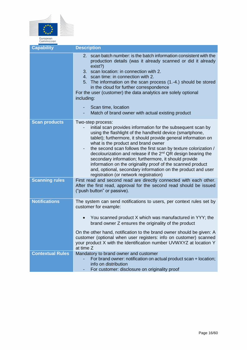
2. scan batch number: is the batch information consistent with the production details (was it already scanned or did it already exist?)
3. scan location: in connection with 2. 4. scan time: in connection with 2. 5. The information on the scan process (1.-4.) should be stored
in the cloud for further correspondence For the user (customer) the data analytics are solely optional
including:
- Scan time, location
- Match of brand owner with actual existing product
Scan products Two-step process: - initial scan provides information for the subsequent scan by
using the flashlight of the handheld device (smartphone, tablet); furthermore, it should provide general information on what is the product and brand owner
- the second scan follows the first scan by texture colorization / decolourization and release if the 2nd QR design bearing the secondary information; furthermore, it should provide information on the originality proof of the scanned product and, optional, secondary information on the product and user registration (or network registration)
Scanning rules First read and second read are directly connected with each other. After the first read, approval for the second read should be issued (“push button” or passive).
Notifications The system can send notifications to users, per context rules set by customer for example:
You scanned product X which was manufactured in YYY; the
brand owner Z ensures the originality of the product
On the other hand, notification to the brand owner should be given: A customer (optional when user registers: info on customer) scanned your product X with the Identification number UVWXYZ at location Y at time Z
Contextual Rules Mandatory to brand owner and customer - For brand owner: notification on actual product scan + location;
info on distribution - For customer: disclosure on originality proof
Page 17/60
2.4 Dynamic Pricing
2.4.1 Use case overview
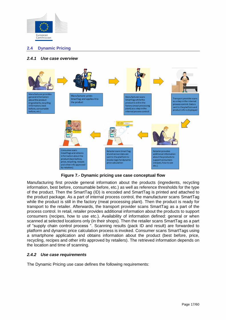
Figure 7.- Dynamic pricing use case conceptual flow
Manufacturing first provide general information about the products (ingredients, recycling information, best before, consumable before, etc.) as well as reference thresholds for the type of the product. Then the SmartTag (ID) is encoded and SmartTag is printed and attached to the product package. As a part of internal process control, the manufacturer scans SmartTag while the product is still in the factory (meat processing plant). Then the product is ready for transport to the retailer. Afterwards, the transport provider scans SmartTag as a part of the process control. In retail, retailer provides additional information about the products to support consumers (recipes, how to use etc.). Availability of information defined: general or when scanned at selected locations only (in their shops). Then the retailer scans SmartTag as a part of “supply chain control process “. Scanning results (pack ID and result) are forwarded to platform and dynamic price calculation process is invoked. Consumer scans SmartTags using a smartphone application and obtains information about the product (best before, price, recycling, recipes and other info approved by retailers). The retrieved information depends on the location and time of scanning. 2.4.2 Use case requirements The Dynamic Pricing use case defines the following requirements:
Page 18/60
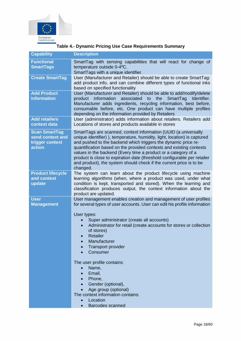
Table 4.- Dynamic Pricing Use Case Requirements Summary
Capability Description
Functional SmartTags
SmartTag with sensing capabilities that will react for change of temperature outside 0-4⁰C.
SmartTags with a unique identifier.
Create SmartTag User (Manufacturer and Retailer) should be able to create SmartTag: add product info, and can combine different types of functional inks based on specified functionality
Add Product information
User (Manufacturer and Retailer) should be able to add/modify/delete product information associated to the SmartTag Identifier. Manufacturer adds ingredients, recycling information, best before, consumable before, etc. One product can have multiple profiles depending on the information provided by Retailers
Add retailers context data
User (administrator) adds information about retailers. Retailers add Locations of stores and products available in stores
Scan SmartTag send context and trigger context action
SmartTags are scanned, context information (UUID (a universally unique identifier) ), temperature, humidity, light, location) is captured and pushed to the backend which triggers the dynamic price re-quantification based on the provided contexts and existing contexts values in the backend (Every time a product or a category of a product is close to expiration date (threshold configurable per retailer and product), the system should check if the current price is to be changed.
Product lifecycle and context update
The system can learn about the product lifecycle using machine learning algorithms (when, where a product was used, under what condition is kept, transported and stored). When the learning and classification produces output, the context information about the product are updated.
User Management
User management enables creation and management of user profiles for several types of user accounts. User can edit his profile information User types:
Super administrator (create all accounts)
Administrator for retail (create accounts for stores or collection of stores)
Retailer
Manufacturer
Transport provider
Consumer The user profile contains:
Name,
Email,
Phone,
Gender (optional),
Age group (optional) The context information contains:
Location
Barcodes scanned
Page 19/60
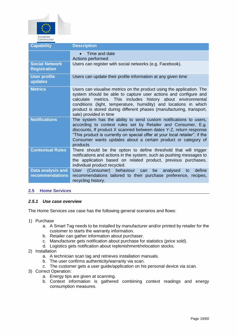
Capability Description
Time and date Actions performed
Social Network Registration
Users can register with social networks (e.g. Facebook).
User profile updates
Users can update their profile information at any given time
Metrics Users can visualise metrics on the product using the application. The system should be able to capture user actions and configure and calculate metrics. This includes history about environmental conditions (light, temperature, humidity) and locations in which product is stored during different phases (manufacturing, transport, sale) provided in time
Notifications The system has the ability to send custom notifications to users, according to context rules set by Retailer and Consumer, E.g. discounts, If product X scanned between dates Y-Z, return response “This product is currently on special offer at your local retailer”; if the Consumer wants updates about a certain product or category of products
Contextual Rules There should be the option to define threshold that will trigger notifications and actions in the system, such as pushing messages to the application based on related product, previous purchases, individual product recycled.
Data analysis and recommendations
User (Consumer) behaviour can be analysed to define recommendations tailored to their purchase preference, recipes, recycling history.
2.5 Home Services
2.5.1 Use case overview
The Home Services use case has the following general scenarios and flows: 1) Purchase
a. A Smart Tag needs to be installed by manufacturer and/or printed by retailer for the customer to starts the warranty information.
b. Retailer can gather information about purchaser. c. Manufacturer gets notification about purchase for statistics (price sold). d. Logistics gets notification about replenishment/relocation stocks.
2) Installation a. A technician scan tag and retrieves installation manuals. b. The user confirms authenticity/warranty via scan. c. The customer gets a user guide/application on his personal device via scan.
3) Correct Operation: a. Energy tips are given at scanning. b. Context information is gathered combining context readings and energy
consumption measures.
Page 20/60
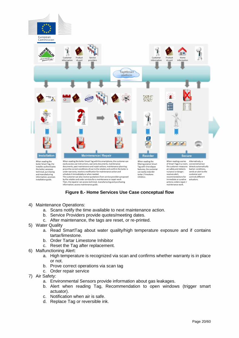
Figure 8.- Home Services Use Case conceptual flow
4) Maintenance Operations:
a. Scans notify the time available to next maintenance action. b. Service Providers provide quotes/meeting dates. c. After maintenance, the tags are reset, or re-printed.
5) Water Quality a. Read SmartTag about water quality/high temperature exposure and if contains
tartar/limestone. b. Order Tartar Limestone Inhibitor c. Reset the Tag after replacement.
6) Malfunctioning Alert: a. High temperature is recognized via scan and confirms whether warranty is in place
or not. b. Prove correct operations via scan tag c. Order repair service
7) Air Safety: a. Environmental Sensors provide information about gas leakages. b. Alert when reading Tag, Recommendation to open windows (trigger smart
actuator). c. Notification when air is safe. d. Replace Tag or reversible ink.
Page 21/60
8) End of Life:
a. Scan notifies that the end of life has been reached. b. Recycling services are informed and provide info for recycling point.
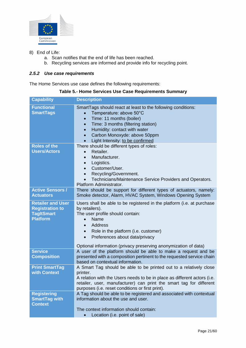
2.5.2 Use case requirements The Home Services use case defines the following requirements:
Table 5.- Home Services Use Case Requirements Summary
Capability Description
Functional SmartTags
SmartTags should react at least to the following conditions:
Temperature: above 50°C
Time: 11 months (boiler)
Time: 3 months (filtering station)
Humidity: contact with water
Carbon Monoxyde: above 50ppm
Light Intensity: to be confirmed
Roles of the Users/Actors
There should be different types of roles:
Retailer.
Manufacturer.
Logistics.
Customer/User.
Recycling/Government.
Technicians/Maintenance Service Providers and Operators. Platform Administrator.
Active Sensors / Actuators
There should be support for different types of actuators, namely: Smoke detector, Alarm, HVAC System, Windows Opening System
Retailer and User Registration to TagItSmart Platform
Users shall be able to be registered in the platform (i.e. at purchase by retailers). The user profile should contain:
Name
Address
Role in the platform (i.e. customer)
Preferences about data/privacy
Optional information (privacy preserving anonymization of data)
Service Composition
A user of the platform should be able to make a request and be presented with a composition pertinent to the requested service chain based on contextual information.
Print SmartTag with Context
A Smart Tag should be able to be printed out to a relatively close printer. A relation with the Users needs to be in place as different actors (i.e. retailer, user, manufacturer) can print the smart tag for different purposes (i.e. reset conditions or first print).
Registering SmartTag with Context
A Tag should be able to be registered and associated with contextual information about the use and user. The context information should contain:
Location (i.e. point of sale)
Page 22/60
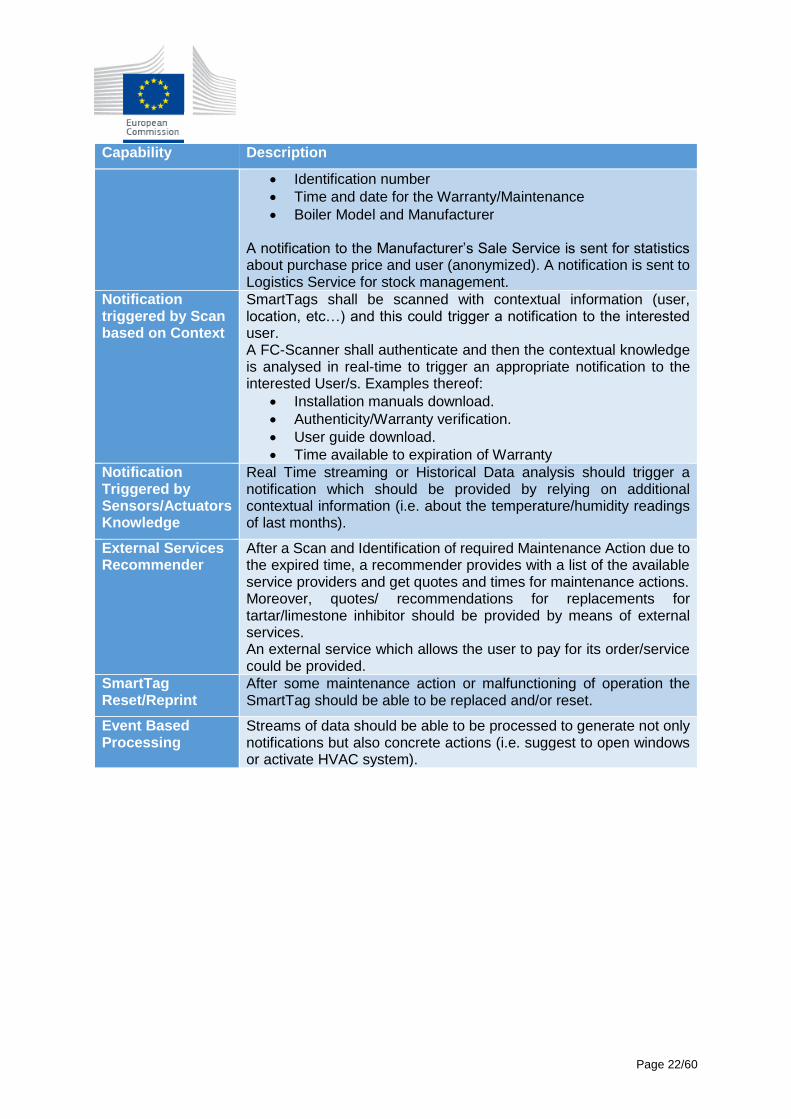
Capability Description
Identification number
Time and date for the Warranty/Maintenance
Boiler Model and Manufacturer
A notification to the Manufacturer’s Sale Service is sent for statistics about purchase price and user (anonymized). A notification is sent to Logistics Service for stock management.
Notification triggered by Scan based on Context
SmartTags shall be scanned with contextual information (user, location, etc…) and this could trigger a notification to the interested user. A FC-Scanner shall authenticate and then the contextual knowledge is analysed in real-time to trigger an appropriate notification to the interested User/s. Examples thereof:
Installation manuals download.
Authenticity/Warranty verification.
User guide download.
Time available to expiration of Warranty
Notification Triggered by Sensors/Actuators Knowledge
Real Time streaming or Historical Data analysis should trigger a notification which should be provided by relying on additional contextual information (i.e. about the temperature/humidity readings of last months).
External Services Recommender
After a Scan and Identification of required Maintenance Action due to the expired time, a recommender provides with a list of the available service providers and get quotes and times for maintenance actions. Moreover, quotes/ recommendations for replacements for tartar/limestone inhibitor should be provided by means of external services. An external service which allows the user to pay for its order/service could be provided.
SmartTag Reset/Reprint
After some maintenance action or malfunctioning of operation the SmartTag should be able to be replaced and/or reset.
Event Based Processing
Streams of data should be able to be processed to generate not only notifications but also concrete actions (i.e. suggest to open windows or activate HVAC system).
Page 23/60
Section 3 - TagItSmart IoT Platform Functional Architecture In the current section, we are going to consider the requirements defined for each use case in the previous section and design what components are needed, providing different views of the platform from the functional point of view. We are not considering deployment aspects so far, where the components live will be defined later in the project, based on the underlying IoT platforms to be utilised in each use case. 3.1 Identified Components and Services
Based on the functional requirements extracted from each use case, we defined which platform components could fulfil the requirements for the different use cases. Based on the different aspects, we can group the different components in the following groups:
Service Management: defines components needed to access, discover and execute services in the platform.
Virtual Entities: defines components to work with virtual representations of the different objects defined in the use cases, from a CPG product to a sensor in a boiler.
SmartTags: defines the components to manage the creation, scanning and management of SmartTags.
Security: defines the components that will implement the authentication, authorisation, and any other security related aspects of the platform.
Domain Management: defines components that are specific to a use case domain.
Utility Services: defines utility components with services shared across use cases.
Application Development Tools: defines the SDKs and tools needed to implement applications on top of the platform.
Each group defines components to cover the different functional areas. Each component can be classified as one of the following types:
Service: software component with internal logic and providing an API.
Data Store: any form of persistent storage technology.
Semantic Model: semantic description of the related entity.
Tools/Library: software component intended to be used in the development of applications using TagItSmart technology.
UI: visual component that serves as the interface for users of different roles to interact with the rest of the components.
Page 24/60
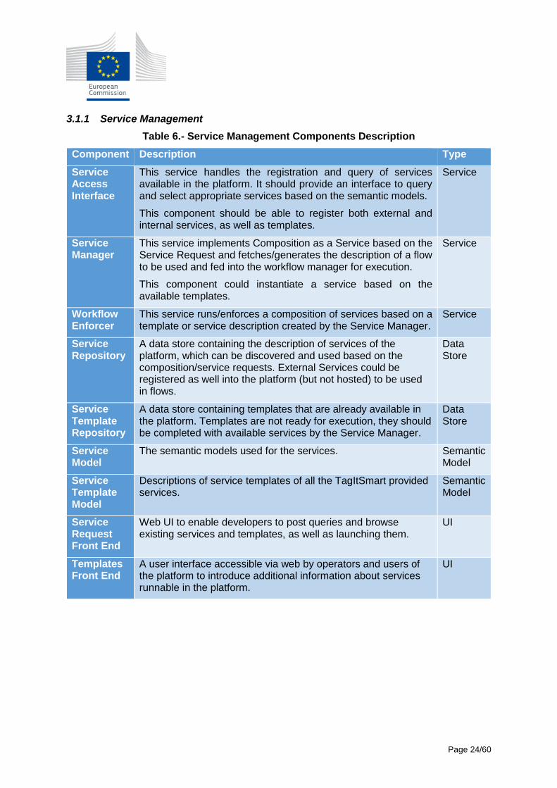
3.1.1 Service Management
Table 6.- Service Management Components Description
Component Description Type
Service Access Interface
This service handles the registration and query of services available in the platform. It should provide an interface to query and select appropriate services based on the semantic models.
This component should be able to register both external and internal services, as well as templates.
Service
Service Manager
This service implements Composition as a Service based on the Service Request and fetches/generates the description of a flow to be used and fed into the workflow manager for execution.
This component could instantiate a service based on the available templates.
Service
Workflow Enforcer
This service runs/enforces a composition of services based on a template or service description created by the Service Manager.
Service
Service Repository
A data store containing the description of services of the platform, which can be discovered and used based on the composition/service requests. External Services could be registered as well into the platform (but not hosted) to be used in flows.
Data Store
Service Template Repository
A data store containing templates that are already available in the platform. Templates are not ready for execution, they should be completed with available services by the Service Manager.
Data Store
Service Model
The semantic models used for the services. Semantic Model
Service Template Model
Descriptions of service templates of all the TagItSmart provided services.
Semantic Model
Service Request Front End
Web UI to enable developers to post queries and browse existing services and templates, as well as launching them.
UI
Templates Front End
A user interface accessible via web by operators and users of the platform to introduce additional information about services runnable in the platform.
UI
Page 25/60
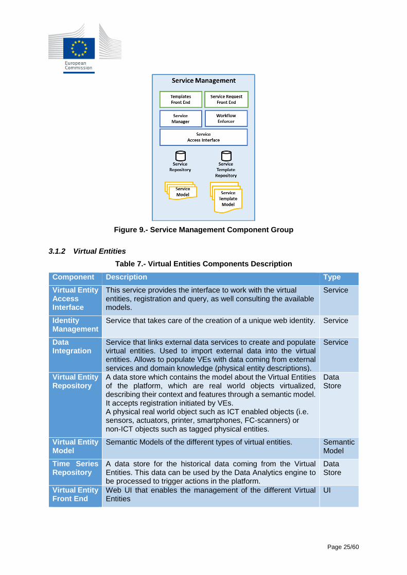
Figure 9.- Service Management Component Group
3.1.2 Virtual Entities
Table 7.- Virtual Entities Components Description
Component Description Type
Virtual Entity Access Interface
This service provides the interface to work with the virtual entities, registration and query, as well consulting the available models.
Service
Identity Management
Service that takes care of the creation of a unique web identity. Service
Data Integration
Service that links external data services to create and populate virtual entities. Used to import external data into the virtual entities. Allows to populate VEs with data coming from external services and domain knowledge (physical entity descriptions).
Service
Virtual Entity Repository
A data store which contains the model about the Virtual Entities of the platform, which are real world objects virtualized, describing their context and features through a semantic model. It accepts registration initiated by VEs. A physical real world object such as ICT enabled objects (i.e. sensors, actuators, printer, smartphones, FC-scanners) or non-ICT objects such as tagged physical entities.
Data Store
Virtual Entity Model
Semantic Models of the different types of virtual entities. Semantic Model
Time Series Repository
A data store for the historical data coming from the Virtual Entities. This data can be used by the Data Analytics engine to be processed to trigger actions in the platform.
Data Store
Virtual Entity Front End
Web UI that enables the management of the different Virtual Entities
UI
Page 26/60
Figure 10.- Virtual Entities Component Group
3.1.3 SmartTags
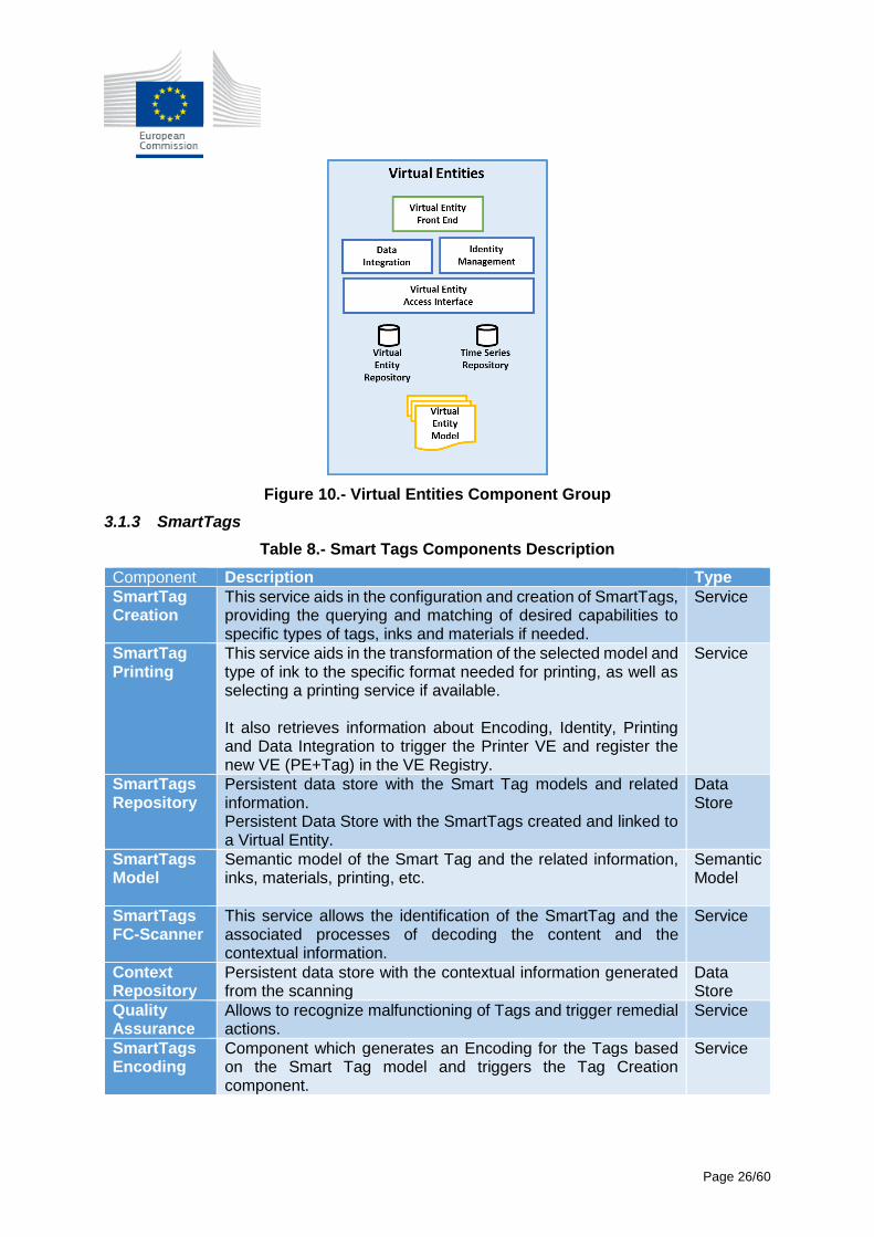
Table 8.- Smart Tags Components Description
Component Description Type
SmartTag Creation
This service aids in the configuration and creation of SmartTags, providing the querying and matching of desired capabilities to specific types of tags, inks and materials if needed.
Service
SmartTag Printing
This service aids in the transformation of the selected model and type of ink to the specific format needed for printing, as well as selecting a printing service if available. It also retrieves information about Encoding, Identity, Printing and Data Integration to trigger the Printer VE and register the new VE (PE+Tag) in the VE Registry.
Service
SmartTags Repository
Persistent data store with the Smart Tag models and related information. Persistent Data Store with the SmartTags created and linked to a Virtual Entity.
Data Store
SmartTags Model
Semantic model of the Smart Tag and the related information, inks, materials, printing, etc.
Semantic Model
SmartTags FC-Scanner
This service allows the identification of the SmartTag and the associated processes of decoding the content and the contextual information.
Service
Context Repository
Persistent data store with the contextual information generated from the scanning
Data Store
Quality Assurance
Allows to recognize malfunctioning of Tags and trigger remedial actions.
Service
SmartTags Encoding
Component which generates an Encoding for the Tags based on the Smart Tag model and triggers the Tag Creation component.
Service
Page 27/60
Component Description Type
SmartTags Front End
Web UI that enables the creation of Smart Tags UI
Figure 11.- Smart Tags Component Group
3.1.4 User Management and Security
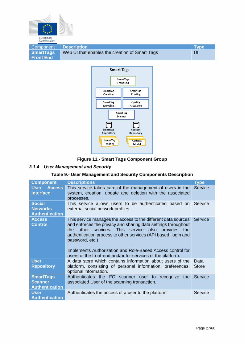
Table 9.- User Management and Security Components Description
Component Descriptions Type
User Access Interface
This service takes care of the management of users in the system, creation, update and deletion with the associated processes.
Service
Social Networks Authentication
This service allows users to be authenticated based on external social network profiles
Service
Access Control
This service manages the access to the different data sources and enforces the privacy and sharing data settings throughout the other services. This service also provides the authentication process to other services (API based, login and password, etc.) Implements Authorization and Role-Based Access control for users of the front-end and/or for services of the platform.
Service
User Repository
A data store which contains information about users of the platform, consisting of personal information, preferences, optional information.
Data Store
SmartTags Scanner Authentication
Authenticates the FC scanner user to recognize the associated User of the scanning transaction.
Service
User Authentication
Authenticates the access of a user to the platform Service
Page 28/60
Component Descriptions Type
User Management Front End
Web UI that enables the user management, A user interface accessible via web by operators and users of the platform to introduce additional information about users of the platform.
UI
User Model Semantic Model describing a user of the platform. Semantic Model
Figure 12.- User Management and Security Component Group
3.1.5 Domain Management
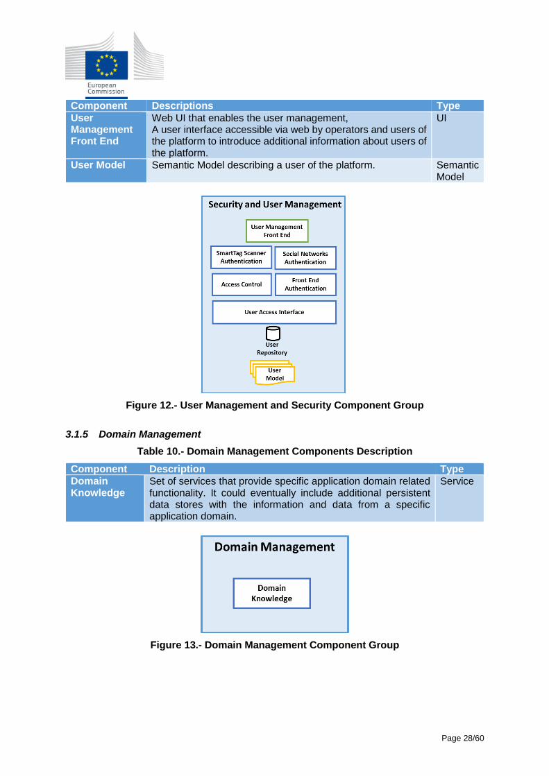
Table 10.- Domain Management Components Description
Component Description Type
Domain Knowledge
Set of services that provide specific application domain related functionality. It could eventually include additional persistent data stores with the information and data from a specific application domain.
Service
Figure 13.- Domain Management Component Group
Page 29/60
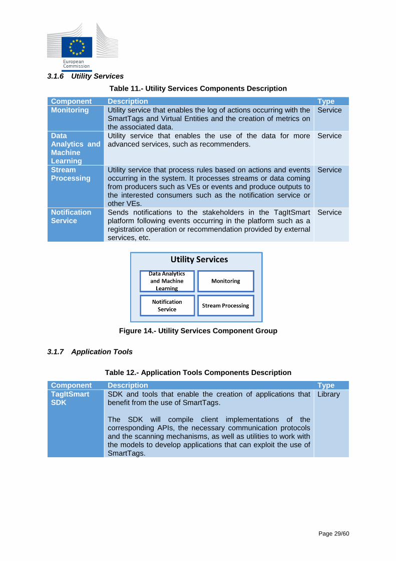
3.1.6 Utility Services
Table 11.- Utility Services Components Description
Component Description Type
Monitoring Utility service that enables the log of actions occurring with the SmartTags and Virtual Entities and the creation of metrics on the associated data.
Service
Data Analytics and Machine Learning
Utility service that enables the use of the data for more advanced services, such as recommenders.
Service
Stream Processing
Utility service that process rules based on actions and events occurring in the system. It processes streams or data coming from producers such as VEs or events and produce outputs to the interested consumers such as the notification service or other VEs.
Service
Notification Service
Sends notifications to the stakeholders in the TagItSmart platform following events occurring in the platform such as a registration operation or recommendation provided by external services, etc.
Service
Figure 14.- Utility Services Component Group
3.1.7 Application Tools
Table 12.- Application Tools Components Description
Component Description Type
TagItSmart SDK
SDK and tools that enable the creation of applications that benefit from the use of SmartTags. The SDK will compile client implementations of the corresponding APIs, the necessary communication protocols and the scanning mechanisms, as well as utilities to work with the models to develop applications that can exploit the use of SmartTags.
Library
Page 30/60
Figure 15.- Application Tools Component Group
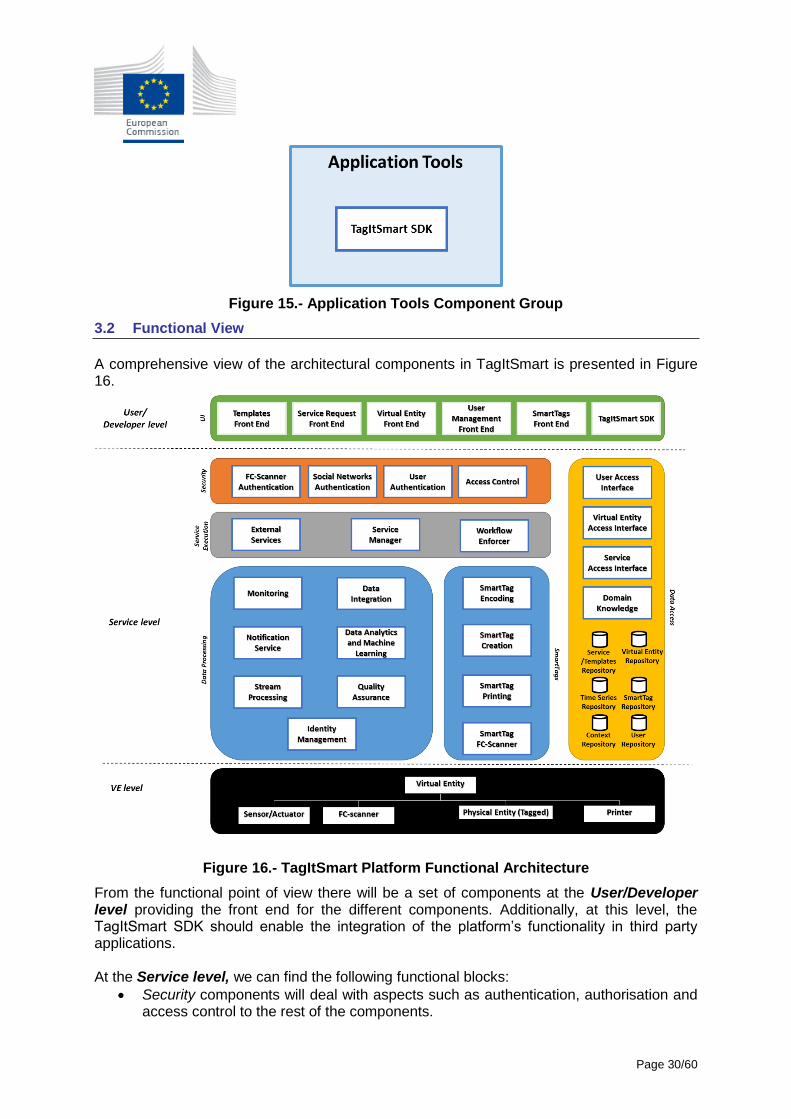
3.2 Functional View
A comprehensive view of the architectural components in TagItSmart is presented in Figure 16.
Figure 16.- TagItSmart Platform Functional Architecture
From the functional point of view there will be a set of components at the User/Developer level providing the front end for the different components. Additionally, at this level, the TagItSmart SDK should enable the integration of the platform’s functionality in third party applications. At the Service level, we can find the following functional blocks:
Security components will deal with aspects such as authentication, authorisation and access control to the rest of the components.
Page 31/60
Service Execution components include those that will enable the execution of services registered in the platform, as well as the service templates that will trigger dynamic creation of workflows.
Data Processing components provide the additional functionality to handle and work with the data generated in the platform
SmartTags components facilitate the integration, creation and scanning of SmartTags.
Data Access components provide the correspondent registries, semantic models and repositories on which TagItSmart will operate.
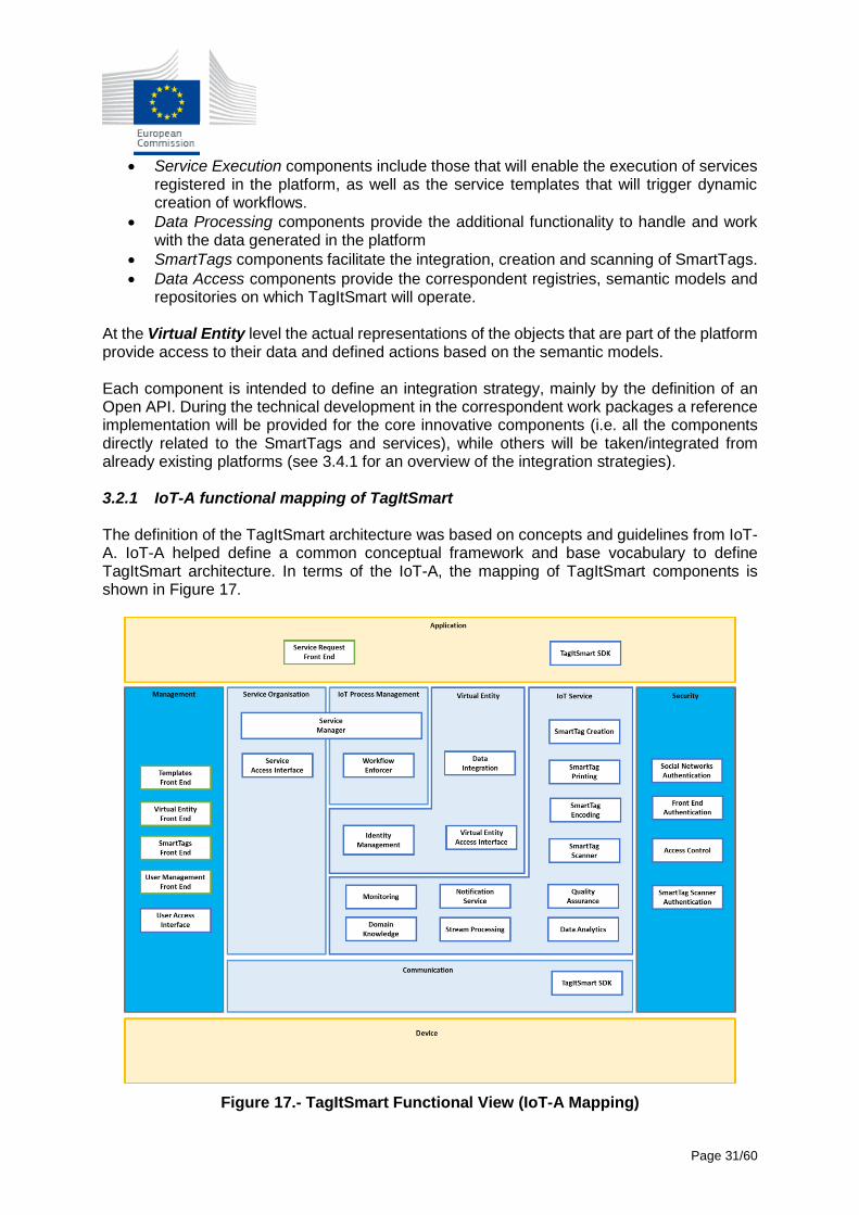
At the Virtual Entity level the actual representations of the objects that are part of the platform provide access to their data and defined actions based on the semantic models. Each component is intended to define an integration strategy, mainly by the definition of an Open API. During the technical development in the correspondent work packages a reference implementation will be provided for the core innovative components (i.e. all the components directly related to the SmartTags and services), while others will be taken/integrated from already existing platforms (see 3.4.1 for an overview of the integration strategies). 3.2.1 IoT-A functional mapping of TagItSmart The definition of the TagItSmart architecture was based on concepts and guidelines from IoT-A. IoT-A helped define a common conceptual framework and base vocabulary to define TagItSmart architecture. In terms of the IoT-A, the mapping of TagItSmart components is shown in Figure 17.
Figure 17.- TagItSmart Functional View (IoT-A Mapping)
Page 32/60
3.2.2 FIWARE functional mapping of TagItSmart The FIWARE GE Open Specifications contains all the information required including
specification of APIs that could be used as a functional block in the TagItSmart platform. The
TagItSmart could employ technology from FIWARE if the GEs are compliant by features they
provide and functionality of the enabler after deployment and integration.
Currently, FIWARE Lab [5], a working instance of FIWARE available for experimentation,
provides a catalogue [6] with available GEs including their description, documentation and
download links.
FIWARE provides technical chapters that could be considered for the TagItSmart platform:
Security: Identity management and Access control are required for front-end users
as well as for identity management for devices
o Security Architecture of FIWARE is using security by design principle by four
main blocks of GEs: Cybersecurity, Identity and Access Management (and
Enforcement), Privacy, Trust and Trustworthiness. Identity management covers
secure and private authentication from users to devices, networks and services,
authorization & trust management, user profile management, privacy-
preserving disposition of personal data, Single Sign-On (SSO) to service
domains and Identity Federation towards applications. The Identity Manager is
the central component that provides a bridge between IdM systems at
connectivity-level and application-level. Steelskin PEP (Policy Enforcement
Point) is a proxy meant to secure Orion Context Broker, by intercepting every
request sent to the Orion, validating it against the Access Control component.
Data/Context Management: Context Broker, IoT Broker, are required in platform for
services to enable functionalities and workflow related to data processing (Stream
processing, Notification service, Data Analytics, Data query) and Data storage.
o FIWARE Data/Context Management GEs allow to gather information from
context and other sources (Context Broker), mediate metadata among GEs and
applications (Metadata pre-processor) query stored information through an
homogeneous layer (Query Broker), generate new data from compressed video
services (Compressed Domain Video Analysis - CDVA), annotate existing
information (Semantic Annotation), store and manage semantic information
(Semantic Application Support), generate new knowledge from big data stores
using a Map & Reduce paradigm (Big Data analysis) and react to different types
of scenarios (Complex Event Processing). Moreover, it provides a Middleware
to allow flexible and efficient communications among GEs and applications. The
current catalogue of available Data/Context Management Ges [6] include Big
Data analysis, Complex Event Processing and Context Broker.
Page 33/60
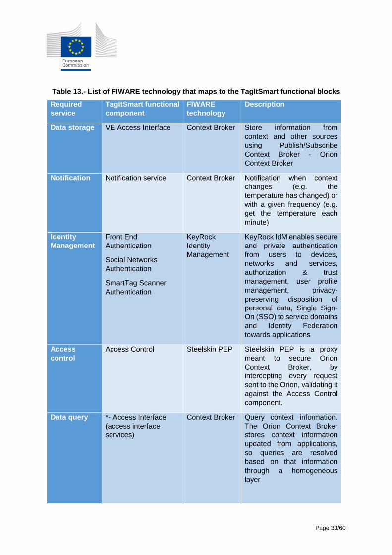
Table 13.- List of FIWARE technology that maps to the TagItSmart functional blocks
Required
service
TagItSmart functional
component
FIWARE
technology
Description
Data storage VE Access Interface
Context Broker Store information from
context and other sources
using Publish/Subscribe
Context Broker - Orion
Context Broker
Notification Notification service Context Broker Notification when context
changes (e.g. the
temperature has changed) or
with a given frequency (e.g.
get the temperature each
minute)
Identity
Management
Front End
Authentication
Social Networks
Authentication
SmartTag Scanner
Authentication
KeyRock
Identity
Management
KeyRock IdM enables secure
and private authentication
from users to devices,
networks and services,
authorization & trust
management, user profile
management, privacy-
preserving disposition of
personal data, Single Sign-
On (SSO) to service domains
and Identity Federation
towards applications
Access
control
Access Control
Steelskin PEP Steelskin PEP is a proxy
meant to secure Orion
Context Broker, by
intercepting every request
sent to the Orion, validating it
against the Access Control
component.
Data query *- Access Interface
(access interface
services)
Context Broker Query context information.
The Orion Context Broker
stores context information
updated from applications,
so queries are resolved
based on that information
through a homogeneous
layer

Page 34/60
Required
service
TagItSmart functional
component
FIWARE
technology
Description
Stream
processing
and Data
analytics
Stream Processing
Data Analytics
Big Data
analysis and
Complex Event
Processing
Generate new knowledge
from big data stores using a
Map & Reduce paradigm and
react to different types of
scenarios
From the TagItSmart architecture (Figure 16) multiple functional blocks can be relayed to the
functionalities provided by FIWARE technology. Data/Context Management from FIWARE
enables gathering, publication, processing and exploitation of information and data streams in
real-time and at massive scale; IdM offers tools for administrators to support the handling of
user life-cycle functions, user registration, user profile management and the modification of
user accounts, for authorising external services to access personal data stored in a secure
environment, etc. All these components are available for experimentation within FI-LAB
catalogue [6].
3.3 Information Views
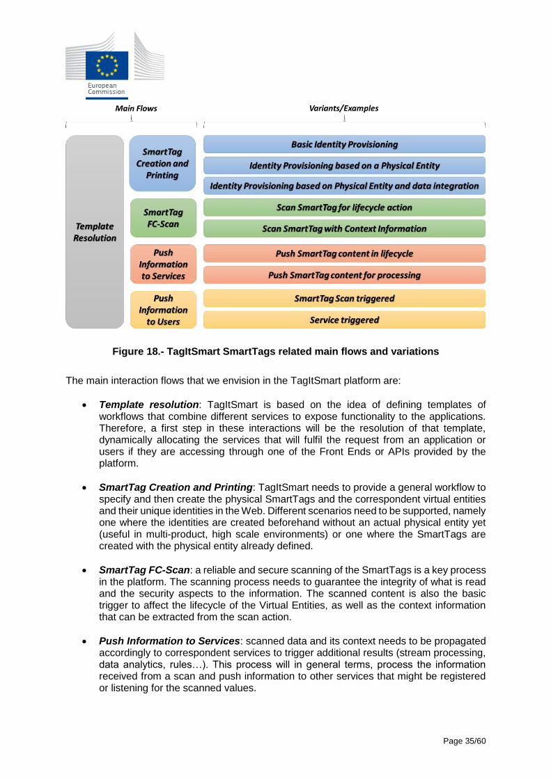
Using terminology from IoT-A, information views define how the different components interact to execute a specific workflow associated with a functionality of the platform. The innovative addition of TagItSmart to an IoT environment is mainly the ability to create the SmartTags and enable a secure environment for scanning and processing the data and context, connecting to additional services when necessary, based on the use cases. From the architectural point of view, the components should provide means to execute different basic flows and their variations to support the use cases. We have identified, as shown in Figure 18, five interactions that are involved in the creation and usage of the SmartTags. These flows might have variations based on the different use case and these aspects need to be considered. In this section, we outline the general interaction mechanisms that will realise each one of the main flows expected in the TagItSmart platform, as well as provide specific examples extracted from the analysis work being done for the different use cases. Many of the interactions are shared among them, so we will outline only relevant examples at this stage of the design. Moreover, at this stage, we only focus on functionality, the deployment of the different components is subject to each use case and other aspects to consider such as scalability and underlying platforms.
Page 35/60
Figure 18.- TagItSmart SmartTags related main flows and variations
The main interaction flows that we envision in the TagItSmart platform are:
Template resolution: TagItSmart is based on the idea of defining templates of workflows that combine different services to expose functionality to the applications. Therefore, a first step in these interactions will be the resolution of that template, dynamically allocating the services that will fulfil the request from an application or users if they are accessing through one of the Front Ends or APIs provided by the platform.
SmartTag Creation and Printing: TagItSmart needs to provide a general workflow to specify and then create the physical SmartTags and the correspondent virtual entities and their unique identities in the Web. Different scenarios need to be supported, namely one where the identities are created beforehand without an actual physical entity yet (useful in multi-product, high scale environments) or one where the SmartTags are created with the physical entity already defined.
SmartTag FC-Scan: a reliable and secure scanning of the SmartTags is a key process in the platform. The scanning process needs to guarantee the integrity of what is read and the security aspects to the information. The scanned content is also the basic trigger to affect the lifecycle of the Virtual Entities, as well as the context information that can be extracted from the scan action.
Push Information to Services: scanned data and its context needs to be propagated accordingly to correspondent services to trigger additional results (stream processing, data analytics, rules…). This process will in general terms, process the information received from a scan and push information to other services that might be registered or listening for the scanned values.
Page 36/60
Push Information to Users: due to the nature of the SmartTags, that require an explicit action from a user to be read, the communication of information to the user is also a common flow defined in TagItSmart. Therefore, how to push information to users in different ways based on events that take place internally needs to be well defined for the different use cases.
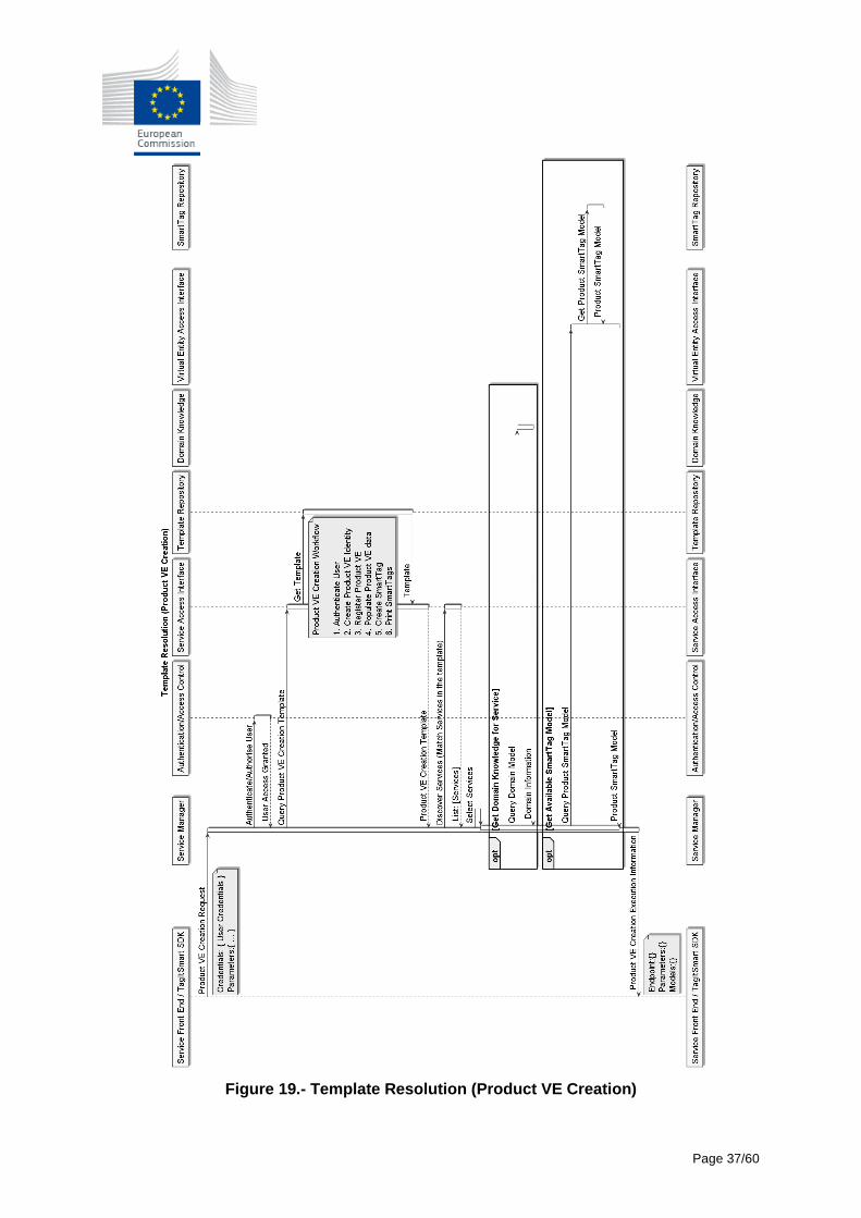
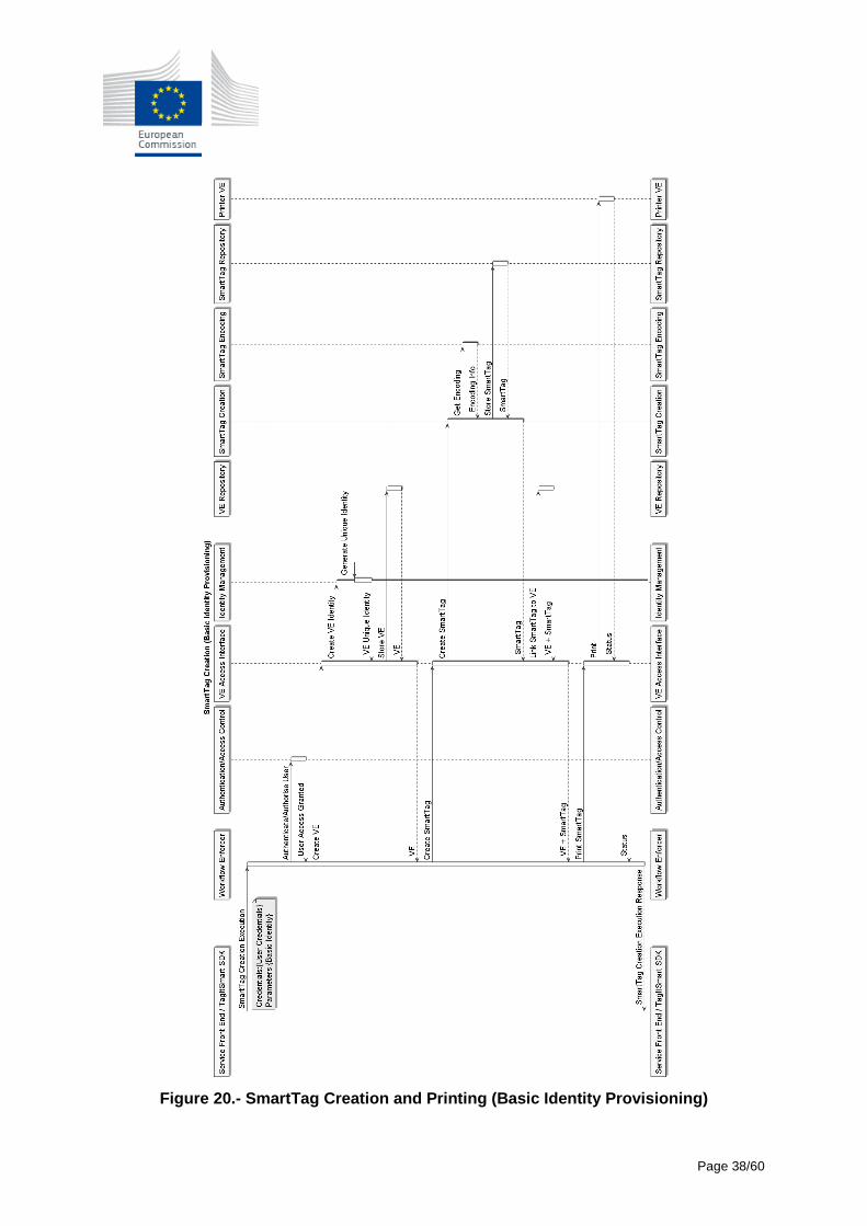
3.3.1 Template Resolution A service request in the TagItSmart platform will be commonly defined by a template name that the Service Manager needs to resolve with actual registered services that outline the workflow to be executed. Different use cases will have different templates defined, some of which would be generic. To exemplify the Template Resolution information flow, we base the example in Figure 19 on a template Product VE Creation that will appear in most of the use cases. The Service Front End (or the correspondent third party application through the TagItSmart SDK) will send a request to create a Product VE. The result of the Template Resolution will be the description of an executable service and all the necessary data needed for the execution based on the correspondent service parameters and defined models. The Service Manager will first authenticate the caller and -if successful- it will search for the appropriate template to create a VE of a Product. Based on the template it will discover the services that need to be used, access some specific domain knowledge if needed, as well as the associated SmartTag model that can be used with that specific type. Based on this it will compile and return all the necessary information to execute that workflow. 3.3.2 SmartTag Creation and Printing Creation of the SmartTags is linked directly to the creation of Virtual Entities, as a SmartTag is a resource of it. To create SmartTags, and depending of the use case, different variations are supported, mainly based on the information available during the creation of the SmartTags and where to get it from. The following sections show concrete examples of some of the more common flows to be found in the use cases. 3.3.2.1 Basic Identity Provisioning In some use cases, e.g. Digital Product, during the label creation phase, Virtual Entities (VE) that have a unique identifier will not necessarily be attached to any physical item, but the SmartTag creation needs to make sure that a unique identifier has been created and reserved only for this VE. This action happens so that a new VE is created and gets a unique identifier for it from Identity Management component. At this point, the SmartTag Creator component needs also to know which type of sensor this SmartTag will have so that it’s able to encode the information correctly into the SmartTag and to send appropriate information to the correspondent Printer VE (see Figure 20). In the Digital Product use case, during the identity provisioning phase, pre-printed labels are scanned and attached to items, this happens at the production line. From TagItSmart architecture point-of-view this means that information related to item (and its production data) are attached to VE later in the process. Usually this information is linked additionally to an external data source (item manufacturer’s database).
Page 37/60
Figure 19.- Template Resolution (Product VE Creation)
Page 38/60
Figure 20.- SmartTag Creation and Printing (Basic Identity Provisioning)
Page 39/60
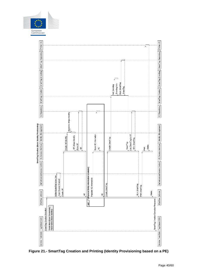
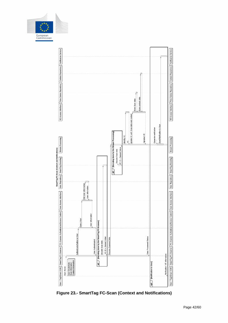
3.3.2.2 Identity Provisioning based on a Physical Entity The flow presented in Figure 21, unlike the previous one, presents the case where the Physical Entity information on which the VE is going to be created is available at the creation time (e.g. as it will be needed for example in the Lifecycle management use case for the creation of products). The difference in this flow is that the VE has specific information that is linked to it, so it must be populated (based on the user or process input). Afterwards the SmartTags need to be created in the same fashion, considering the type of encoding selected and the printing format to send to the corresponding Printer VE. 3.3.2.3 Identity Provisioning based on a Physical Entity and Data Integration In Figure 22 it is possible to view the process of creating and printing a SmartTag when the information of the Physical Entity lives in an external system (typically when integrating with legacy systems or already existing enterprise services. This is a common scenario, for example, to be applied to a product in the Home Service use case (i.e. a boiler). This process in comparison with the other variations of SmartTag creation and printing adds the intervention of the Data Integration component, which will be responsible for interacting with any external service and domain knowledge necessary to populate the VE with its information. 3.3.3 SmartTag FC-Scan / Push Information to Services / Push Information to Users The following sections show examples of these three types of interactions together, as they usually occur, though in some cases the processes could be separated, see section 3.3.4 for an example. 3.3.3.1 SmartTag FC-scan (Context and Notifications) The purpose of this flow (see Figure 23) is to show the case where a SmartTag is scanned and information related to the context of the user and to the lifecycle of the product is sent to the user as a notification. This requires that FC-scanner first checks the credentials and authenticates the user and itself if necessary. It is also possible that the user identity is required for some actions. The decoding action can happen either on the SmartTag FC-Scanner as well as carried out by the Stream Processing once the event is received. This will depend on the implementation of the scanner. In either case, SmartTag FC-Scanner sends a request to TagItSmart platform with the scanned data. This will trigger the Stream Processing where the VE will be identify and the scanned information updated. Consequently, and depending on the content, additional operations will be triggered. In this case, after the scanning procedure, a push notification is sent to the user to provide him with relevant information about the VE scanned after the scanning is processed. As an example, pushing information to users is a common situation in the Digital Product use case, this happens when item manufacturer (items first owner) wants to push notification to current owner of the item as they scan it. There are additional implications, such as the need for some actions to protect the identity of current owner of the item while sharing the information, which will be validated by the security components.
Page 40/60
Figure 21.- SmartTag Creation and Printing (Identity Provisioning based on a PE)

Page 41/60
Figure 22 – SmartTag Creation and Printing (Identity Provisioning based on a PE and Data Integration)
Page 42/60
Figure 23.- SmartTag FC-Scan (Context and Notifications)
Page 43/60
3.3.3.2 SmartTag FC-Scan (Context and Notifications with External Services) In the flow shown in Figure 24, scanning a product from a user of correspondent application through the TagItSmart SDK can trigger a call to an external service, for example, to obtain recycling information based on the context of the scan (location, time, product materials, user…). The scanning process follows the same structure, first the context information and user credentials are gathered and sent to the SmartTag FC-Scanner, which afterwards, decodes and forwards the event further to the platform to react on the scan, therefore the SmartTag is read from the product, the context is captured in the correspondent device and sent to the Stream Processing to fulfil the request for recycling information. This must be as well authenticated and then a Scan event triggered that will decode the SmartTag value, lookup for the correspondent User VE and Product VE, update then accordingly with the decoded value, and trigger the connection to the external service to provide the recycling information back to the user or application. 3.3.3.3 SmartTag FC-Scan (Complex rules) In Figure 25 we show a bit more complex flow for processing the scan. It defines the same steps to get the information about the VE scanned, but relies on more complex logic to process the event, combining notifications, domain knowledge updates, context information handling, external services and actions on VEs that are physical devices. It is based on the Home Services Use Case, where it is possible to scan a SmartTag via an FC-Scanner and send a notification to the interested user, i.e. about the status of the warranty or about some maintenance action required with optionally the possibility to invoke external services for quotes about replacements (i.e. tartar/limestone inhibitor) or maintenance service. Moreover, it is possible to optionally reset or clear the status of the SmartTag. Following a Scan action by the user of an FC-Scanner, and after the authentication and decoding process, the associated Virtual Entity is updated and the Stream Processing component triggers the complex rule, in this case the Warranty Check rule, which will update the User location and FC-Scanner location and then coordinate the gathering of Domain Knowledge (warranty information), the External Services (get quote information) as well as a lookup on the available Displays to send the notification. 3.3.4 Push Information to Services/Users to actuate on a device Though the scanning of the SmartTags will drive most of the interactions, the platform will also support the integration with Physical Entities that send information on sensed values through other means, e.g. an embedded sensor that is physically connected to a device. In Figure 26 it is possible to view the process of triggering a notification to the interested user based on the monitoring of some parameters via a Sensor VE, i.e. an alarm following the detection of a smoke presence. This could also trigger an Actuator VE such as a Window Opener VE or any general HVAC System actuating VE. In this case, the Smoke Detector sends periodically data to update the Smoke Detector VE and its correspondent Time Series Repository. This will trigger the Stream Processing component, that will rule the logic associated with that event, in this case, we are considering an example where upon a threshold violation, it finds a relevant Display VE to notify the interested user. A Window VE is looked up too and a notification is sent to open it.
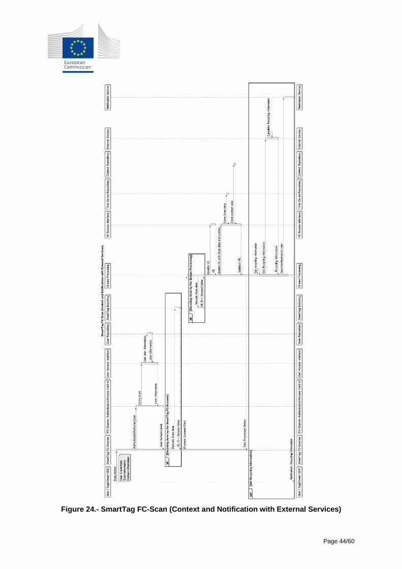
Page 44/60
Figure 24.- SmartTag FC-Scan (Context and Notification with External Services)
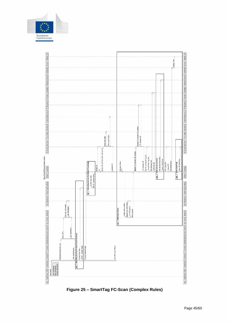
Page 45/60
Figure 25 – SmartTag FC-Scan (Complex Rules)
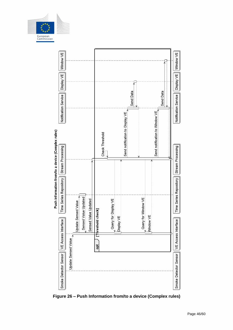
Page 46/60
Figure 26 – Push Information from/to a device (Complex rules)
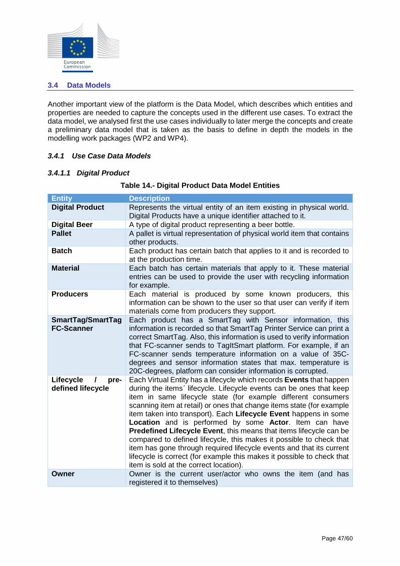
Page 47/60
3.4 Data Models
Another important view of the platform is the Data Model, which describes which entities and properties are needed to capture the concepts used in the different use cases. To extract the data model, we analysed first the use cases individually to later merge the concepts and create a preliminary data model that is taken as the basis to define in depth the models in the modelling work packages (WP2 and WP4).
3.4.1 Use Case Data Models 3.4.1.1 Digital Product
Table 14.- Digital Product Data Model Entities
Entity Description
Digital Product Represents the virtual entity of an item existing in physical world. Digital Products have a unique identifier attached to it.
Digital Beer A type of digital product representing a beer bottle.
Pallet A pallet is virtual representation of physical world item that contains other products.
Batch Each product has certain batch that applies to it and is recorded to at the production time.
Material Each batch has certain materials that apply to it. These material entries can be used to provide the user with recycling information for example.
Producers Each material is produced by some known producers, this information can be shown to the user so that user can verify if item materials come from producers they support.
SmartTag/SmartTag FC-Scanner
Each product has a SmartTag with Sensor information, this information is recorded so that SmartTag Printer Service can print a correct SmartTag. Also, this information is used to verify information that FC-scanner sends to TagItSmart platform. For example, if an FC-scanner sends temperature information on a value of 35C-degrees and sensor information states that max. temperature is 20C-degrees, platform can consider information is corrupted.
Lifecycle / pre-defined lifecycle
Each Virtual Entity has a lifecycle which records Events that happen during the items´ lifecycle. Lifecycle events can be ones that keep item in same lifecycle state (for example different consumers scanning item at retail) or ones that change items state (for example item taken into transport). Each Lifecycle Event happens in some Location and is performed by some Actor. Item can have Predefined Lifecycle Event, this means that items lifecycle can be compared to defined lifecycle, this makes it possible to check that item has gone through required lifecycle events and that its current lifecycle is correct (for example this makes it possible to check that item is sold at the correct location).
Owner Owner is the current user/actor who owns the item (and has registered it to themselves)
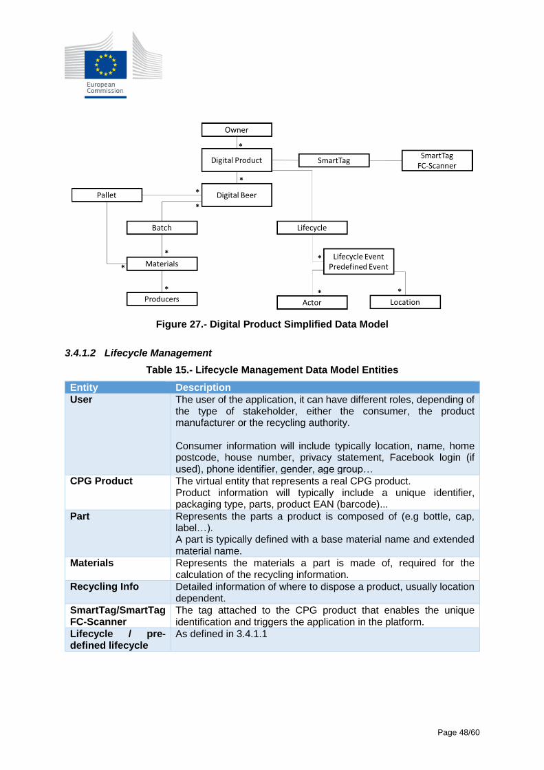
Page 48/60
Figure 27.- Digital Product Simplified Data Model
3.4.1.2 Lifecycle Management
Table 15.- Lifecycle Management Data Model Entities
Entity Description
User The user of the application, it can have different roles, depending of the type of stakeholder, either the consumer, the product manufacturer or the recycling authority. Consumer information will include typically location, name, home postcode, house number, privacy statement, Facebook login (if used), phone identifier, gender, age group…
CPG Product The virtual entity that represents a real CPG product. Product information will typically include a unique identifier, packaging type, parts, product EAN (barcode)...
Part Represents the parts a product is composed of (e.g bottle, cap, label…). A part is typically defined with a base material name and extended material name.
Materials Represents the materials a part is made of, required for the calculation of the recycling information.
Recycling Info Detailed information of where to dispose a product, usually location dependent.
SmartTag/SmartTag FC-Scanner
The tag attached to the CPG product that enables the unique identification and triggers the application in the platform.
Lifecycle / pre-defined lifecycle
As defined in 3.4.1.1
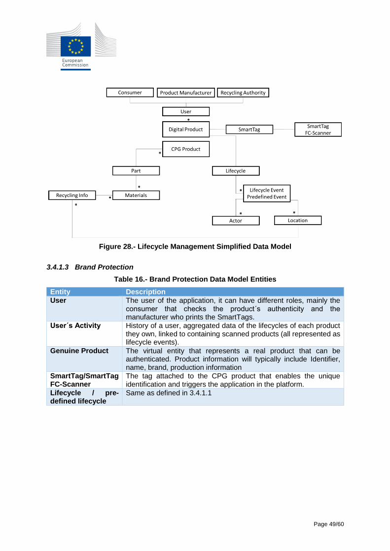
Page 49/60
Figure 28.- Lifecycle Management Simplified Data Model
3.4.1.3 Brand Protection
Table 16.- Brand Protection Data Model Entities
Entity Description
User The user of the application, it can have different roles, mainly the consumer that checks the product´s authenticity and the manufacturer who prints the SmartTags.
User´s Activity History of a user, aggregated data of the lifecycles of each product they own, linked to containing scanned products (all represented as lifecycle events).
Genuine Product The virtual entity that represents a real product that can be authenticated. Product information will typically include Identifier, name, brand, production information
SmartTag/SmartTag FC-Scanner
The tag attached to the CPG product that enables the unique identification and triggers the application in the platform.
Lifecycle / pre-defined lifecycle
Same as defined in 3.4.1.1
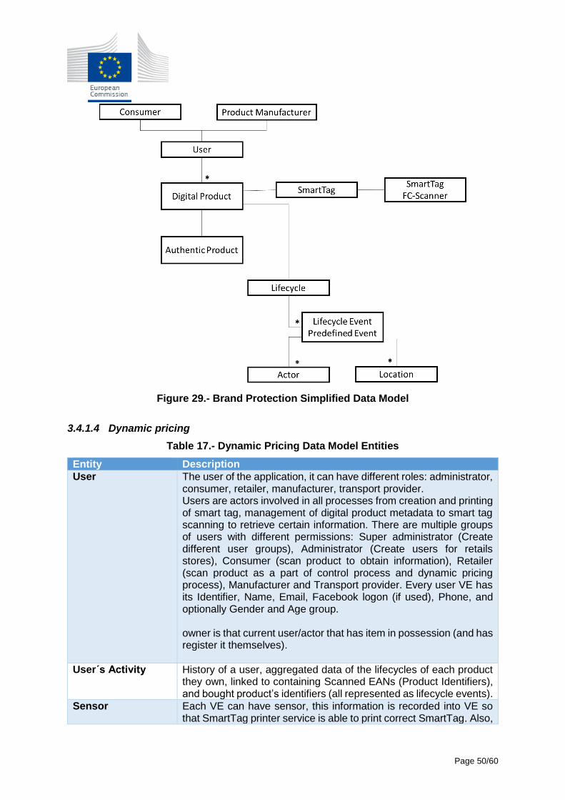
Page 50/60
Figure 29.- Brand Protection Simplified Data Model
3.4.1.4 Dynamic pricing
Table 17.- Dynamic Pricing Data Model Entities
Entity Description
User The user of the application, it can have different roles: administrator, consumer, retailer, manufacturer, transport provider. Users are actors involved in all processes from creation and printing of smart tag, management of digital product metadata to smart tag scanning to retrieve certain information. There are multiple groups of users with different permissions: Super administrator (Create different user groups), Administrator (Create users for retails stores), Consumer (scan product to obtain information), Retailer (scan product as a part of control process and dynamic pricing process), Manufacturer and Transport provider. Every user VE has its Identifier, Name, Email, Facebook logon (if used), Phone, and optionally Gender and Age group. owner is that current user/actor that has item in possession (and has register it themselves).
User´s Activity History of a user, aggregated data of the lifecycles of each product they own, linked to containing Scanned EANs (Product Identifiers), and bought product’s identifiers (all represented as lifecycle events).
Sensor Each VE can have sensor, this information is recorded into VE so that SmartTag printer service is able to print correct SmartTag. Also,
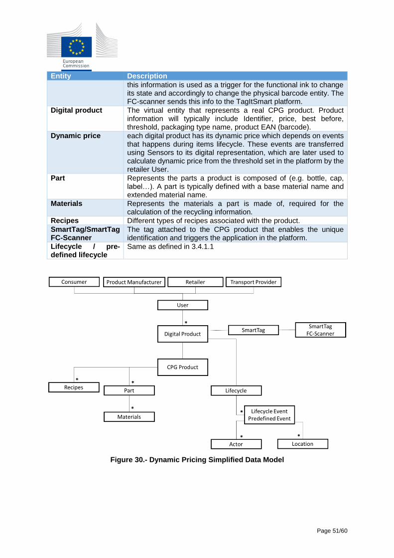
Page 51/60
Entity Description
this information is used as a trigger for the functional ink to change its state and accordingly to change the physical barcode entity. The FC-scanner sends this info to the TagItSmart platform.
Digital product The virtual entity that represents a real CPG product. Product information will typically include Identifier, price, best before, threshold, packaging type name, product EAN (barcode).
Dynamic price each digital product has its dynamic price which depends on events that happens during items lifecycle. These events are transferred using Sensors to its digital representation, which are later used to calculate dynamic price from the threshold set in the platform by the retailer User.
Part Represents the parts a product is composed of (e.g. bottle, cap, label…). A part is typically defined with a base material name and extended material name.
Materials Represents the materials a part is made of, required for the calculation of the recycling information.
Recipes Different types of recipes associated with the product.
SmartTag/SmartTag FC-Scanner
The tag attached to the CPG product that enables the unique identification and triggers the application in the platform.
Lifecycle / pre-defined lifecycle
Same as defined in 3.4.1.1
Figure 30.- Dynamic Pricing Simplified Data Model
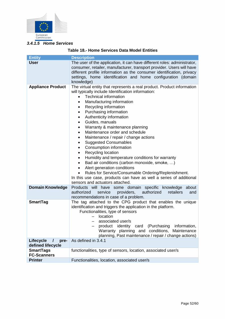
Page 52/60
3.4.1.5 Home Services
Table 18.- Home Services Data Model Entities
Entity Description
User The user of the application, it can have different roles: administrator, consumer, retailer, manufacturer, transport provider. Users will have different profile information as the consumer identification, privacy settings, home identification and home configuration (domain knowledge)
Appliance Product The virtual entity that represents a real product. Product information will typically include Identification information:
Technical information
Manufacturing information
Recycling information
Purchasing information
Authenticity information
Guides, manuals
Warranty & maintenance planning
Maintenance order and schedule
Maintenance / repair / change actions
Suggested Consumables
Consumption information
Recycling location
Humidity and temperature conditions for warranty
Bad air conditions (carbon monoxide, smoke, …)
Alert generation conditions
Rules for Service/Consumable Ordering/Replenishment. In this use case, products can have as well a series of additional sensors and actuators attached.
Domain Knowledge Products will have some domain specific knowledge about authorized service providers, authorized retailers and recommendations in case of a problem.
SmartTag The tag attached to the CPG product that enables the unique identification and triggers the application in the platform. Functionalities, type of sensors
– location – associated user/s – product identity card (Purchasing information,
Warranty planning and conditions, Maintenance planning, Past maintenance / repair / change actions)
Lifecycle / pre-defined lifecycle
As defined in 3.4.1
SmartTags FC-Scanners
functionalities, type of sensors, location, associated user/s
Printer Functionalities, location, associated user/s
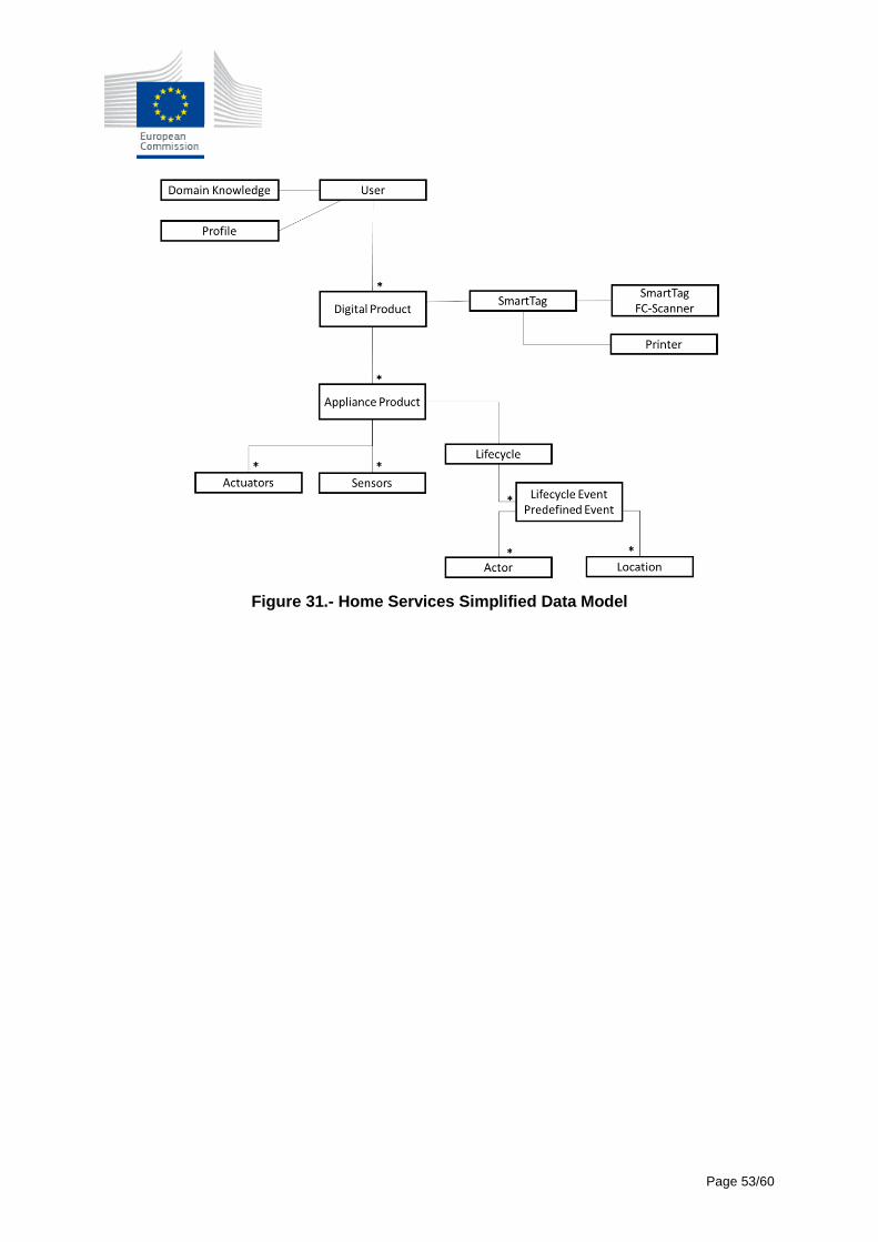
Page 53/60
Figure 31.- Home Services Simplified Data Model
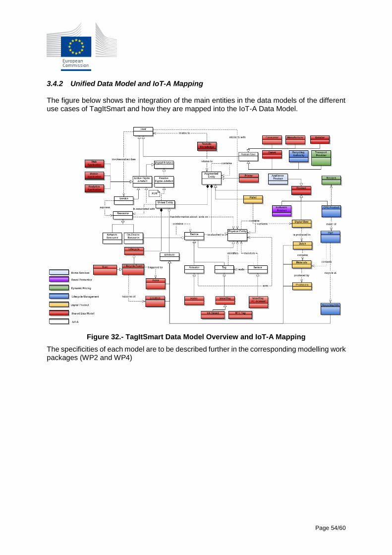
Page 54/60
3.4.2 Unified Data Model and IoT-A Mapping The figure below shows the integration of the main entities in the data models of the different use cases of TagItSmart and how they are mapped into the IoT-A Data Model.
Figure 32.- TagItSmart Data Model Overview and IoT-A Mapping
The specificities of each model are to be described further in the corresponding modelling work packages (WP2 and WP4)
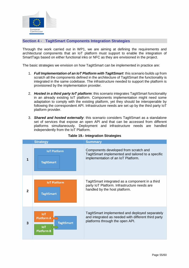
Page 55/60
Section 4 - TagItSmart Components Integration Strategies Through the work carried out in WP1, we are aiming at defining the requirements and architectural components that an IoT platform must support to enable the integration of SmartTags based on either functional inks or NFC as they are envisioned in the project. The basic strategies we envision on how TagItSmart can be implemented in practice are:
1. Full Implementation of an IoT Platform with TagItSmart: this scenario builds up from scratch all the components defined in the architecture of TagItSmart the functionality is integrated in the same codebase. The infrastructure needed to support the platform is provisioned by the implementation provider.
2. Hosted in a third party IoT platform: this scenario integrates TagItSmart functionality
in an already existing IoT platform. Components implementation might need some adaptation to comply with the existing platform, yet they should be interoperable by following the correspondent API. Infrastructure needs are set up by the third party IoT platform provider.
3. Shared and hosted externally: this scenario considers TagItSmart as a standalone
set of services that expose an open API and that can be accessed from different platforms simultaneously. Deployment and infrastructure needs are handled independently from the IoT Platform.
Table 19.- Integration Strategies
Strategy Summary
1
Components developed from scratch and TagItSmart implemented and tailored to a specific implementation of an IoT Platform.
2
TagItSmart integrated as a component in a third party IoT Platform. Infrastructure needs are handled by the host platform.
3
TagItSmart implemented and deployed separately and integrated as needed with different third party platforms through the open API.
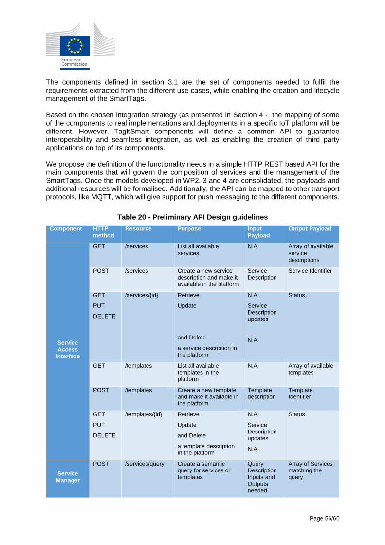
Page 56/60
The components defined in section 3.1 are the set of components needed to fulfil the requirements extracted from the different use cases, while enabling the creation and lifecycle management of the SmartTags. Based on the chosen integration strategy (as presented in Section 4 - the mapping of some of the components to real implementations and deployments in a specific IoT platform will be different. However, TagItSmart components will define a common API to guarantee interoperability and seamless integration, as well as enabling the creation of third party applications on top of its components. We propose the definition of the functionality needs in a simple HTTP REST based API for the main components that will govern the composition of services and the management of the SmartTags. Once the models developed in WP2, 3 and 4 are consolidated, the payloads and additional resources will be formalised. Additionally, the API can be mapped to other transport protocols, like MQTT, which will give support for push messaging to the different components.
Table 20.- Preliminary API Design guidelines
Component HTTP method
Resource Purpose Input Payload
Output Payload
Service Access
Interface
GET
/services
List all available services
N.A. Array of available service descriptions
POST /services Create a new service description and make it available in the platform
Service Description
Service Identifier
GET
PUT
DELETE
/services/{id} Retrieve
Update
and Delete
a service description in the platform
N.A.
Service Description updates
N.A.
Status
GET /templates List all available templates in the platform
N.A. Array of available templates
POST /templates Create a new template and make it available in the platform
Template description
Template Identifier
GET
PUT
DELETE
/templates/{id} Retrieve
Update
and Delete
a template description in the platform
N.A.
Service Description updates
N.A.
Status
Service Manager
POST /services/query Create a semantic query for services or templates
Query Description Inputs and Outputs needed
Array of Services matching the query
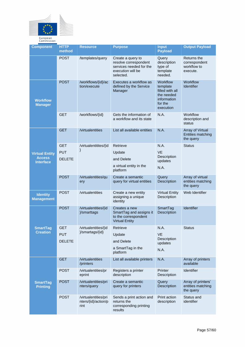
Page 57/60
Component HTTP method
Resource Purpose Input Payload
Output Payload
POST /templates/query Create a query to resolve correspondent services needed for the execution will be selected.
Query description type of template needed.
Returns the correspondent workflow to execute.
Workflow Manager
POST /workflows/{id}/action/execute
Executes a workflow as defined by the Service Manager
Workflow template filled with all the needed information for the execution
Workflow Identifier
GET /workflows/{id} Gets the information of a workflow and its state
N.A. Workflow description and status
Virtual Entity Access
Interface
GET
/virtualentities
List all available entities N.A. Array of Virtual Entities matching the query
GET
PUT
DELETE
/virtualentitites/{id}
Retrieve
Update
and Delete
a virtual entity in the platform
N.A.
VE Description updates
N.A.
Status
POST /virtualentities/query
Create a semantic query for virtual entities
Query Description
Array of virtual entities matching the query
Identity Management
POST /virtualentities Create a new entity assigning a unique identity
Virtual Entity Description
Web Identifier
SmartTag Creation
POST /virtualentities/{id}/smarttags
Creates a new SmartTag and assigns it to the correspondent Virtual Entity
SmartTag Description
Identifier
GET
PUT
DELETE
/virtualentities/{id}/smartags/{id}
Retrieve
Update
and Delete
a SmartTag in the platform
N.A.
VE Description updates
N.A.
Status
SmartTag Printing
GET /virtualentities /printers
List all available printers N.A. Array of printers available
POST /virtualentities/preprint
Registers a printer description
Printer Description
Identifier
POST /virtualentities/printers/query
Create a semantic query for printers
Query Description
Array of printers’ entities matching the query
POST /virtualentities/printers/{id}/action/print
Sends a print action and returns the corresponding printing results
Print action description
Status and identifier
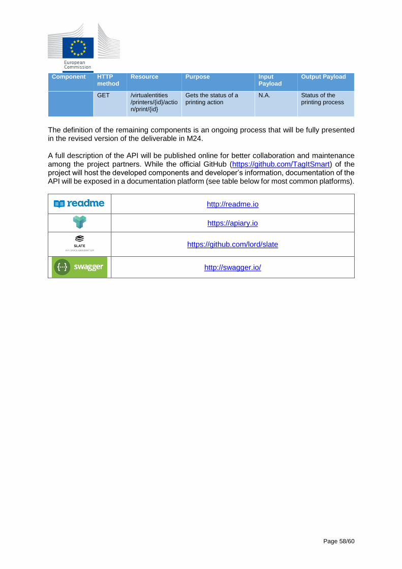
Page 58/60
Component HTTP method
Resource Purpose Input Payload
Output Payload
GET /virtualentities /printers/{id}/action/print/{id}
Gets the status of a printing action
N.A. Status of the printing process
The definition of the remaining components is an ongoing process that will be fully presented in the revised version of the deliverable in M24. A full description of the API will be published online for better collaboration and maintenance among the project partners. While the official GitHub (https://github.com/TagItSmart) of the project will host the developed components and developer’s information, documentation of the API will be exposed in a documentation platform (see table below for most common platforms).
http://readme.io
https://apiary.io
https://github.com/lord/slate
http://swagger.io/

Page 59/60
Section 5 - Conclusions and Future Work TagItSmart is a use case driven project that aims to implement several pilots that cover different stages and applications on the lifecycle of digital products. The goal of this deliverable was to establish the architectural foundations to give technical guidance to those use cases in a comprehensive set of components that can then be choreographed as part of the TagItSmart value proposition. We are not aiming at defining yet another IoT architecture, therefore we have been focused on selecting and defining the functional components needed to cover the innovation of the project, defined around the SmartTags and their lifecycle management, components that will then be realised by specific implementations or by already existing components in other platforms of choice. The architecture was defined by analysing already existing IoT reference architectures that could help TagItSmart adopt a common vocabulary and understanding for the definition of the components. We aligned to the IoT-A reference model with this objective in mind. Next, we expanded on the requirements of each use case from a technical-functional point of view to be able to aggregate and extract the generic components needed in the platform. Based on the IoT-A reference model, we identified the components and provide the functional view of the architecture, the most relevant information views and the high-level data models linked to each use case. We started as well an early design of an open API that will enable the development and integration of TagItSmart specific components. This serves as the reference document to further expand on the technical design in subsequent Work Packages 2, 3 and 4. As part of this work we also analysed possible integration strategies that use cases will need to select in WP5 during their execution. The next steps in the architectural work will be to validate the initial architecture in each use case as part of the development work and refine it if necessary. During the piloting phase, also aspects of real scalability and performance, as well as security will be further specified. The API of each component needs integrating with the models defined in WP2 and WP4, which will serve as well as a mutual validation step.
Page 60/60
Section 6 - References
[1] “FIWARE Architecture,” [Online]. Available: https://forge.fiware.org/plugins/mediawiki/wiki/fiware/index.php/FIWARE_Architecture.
[2] “SocIoTal Platform,” [Online]. Available: http://sociotal.eu/.
[3] “IoT-A Project,” [Online]. Available: http://www.iot-a.eu/.
[4] “IoT-A D1.5 deliverable “Final architecture reference model for the IoT v3”,” July 2013.
[5] “FIWARE LAB, THE OPEN INNOVATION LAB,” [Online]. Available: https://www.fiware.org/lab/.
[6] “FIWARE Lab Generic Enablers,” [Online]. Available: https://catalogue.fiware.org/enablers.