D. Romeu. - Revista Latinoamericana de Metalurgia y …2)/RLMM Art-01V21N2-p13.pdf · D. Romeu....
8
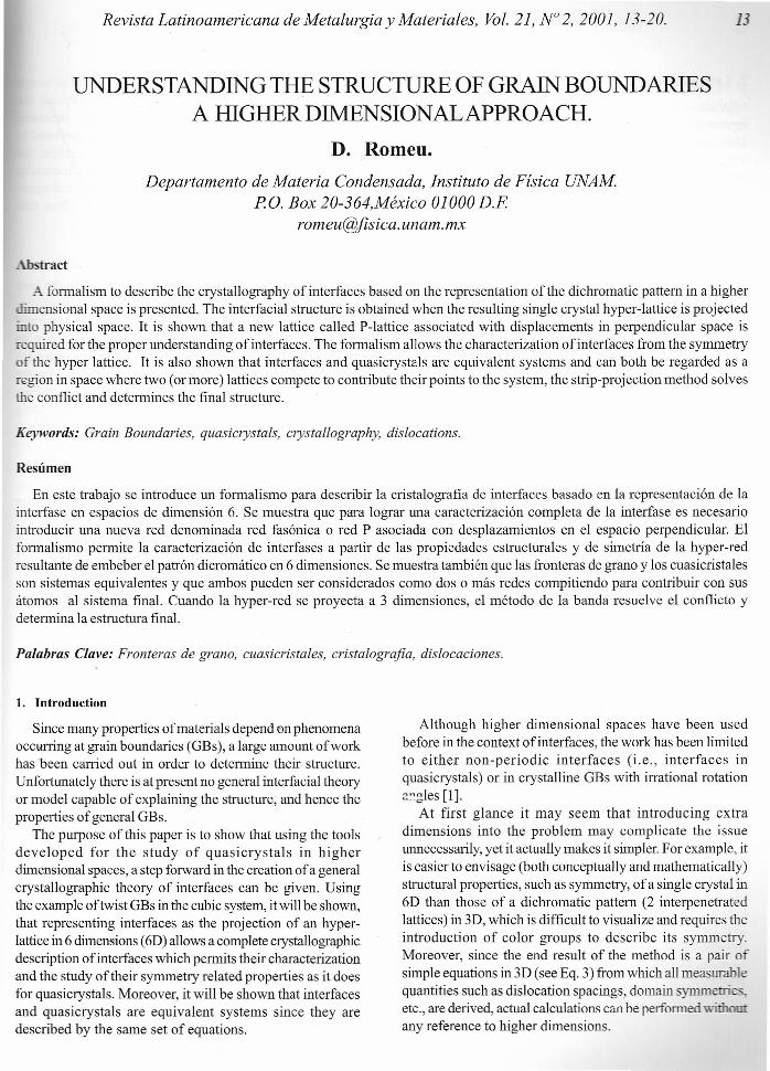
Revista Latinoamericana de Metalurgia y Materiales, Vol. 21, N° 2,2001, 13-20. 13 UNDERSTANDING THE STRUCTURE OF GRAIN BOUNDARIES A HIGHER DIMENSIONALAPPROACH. D. Romeu. Departamento de Materia Condensada, Instituto de Física UNAM P. o. Box 20-364,México 01000 D.F romeu@jisica. unam. mx Abstraer A formalism to describe the crystallography of interfaces based on the representation of the dichromatic pattern in a higher dimensional space is presented. The interfacial structure is obtained when the resulting single crystal hyper-lattice is projected into physical space. It is shown, that a new lattice called P-lattice associated with displacements in perpendicular space is required for the proper understanding of interfaces. The formalism allows the characterization of interfaces from the symmetry of the hyper lattice. It is also shown that interfaces and quasicrystals are equivalent systems and can both be regarded as a region in space where two (or more) lattices compete to contribute their points to the system, the strip-projection method solves the conflict and determines the final structure. Resúmen Keywords: Grain Boundaries, quasicrystals, crystallography, dislocations. En este trabajo se introduce un formalismo para describir la cristalografia de interfaces basado en la representación de la interfase en espacios de dimensión 6. Se muestra que para lograr una caracterización completa de la interfase es necesario introducir una nueva red denominada red fasónica o red P asociada con desplazamientos en el espacio perpendicular. El formalismo permite la caracterización de interfases a partir de las propiedades estructurales y de simetría de la hyper-red resultante de embeber el patrón dicromático en 6 dimensiones. Se muestra también que las fronteras de grano y los cuasicristales son sistemas equivalentes y que ambos pueden ser considerados como dos o más redes compitiendo para contribuir con sus átomos al sistema fmal. Cuando la hyper-red se proyecta a 3 dimensiones, el método de la banda resuelve el conflicto y determina la estructura final. Palabras Clave: Fronteras de grano, cuasicristales, cristalografia, dislocaciones. 1. Introduction Since many properties of materials dependen phenomena occurring at grain boundaries (GBs), a large amount of work has been carried out in order to determine their structure. Unfortunately there is at present no general interfacial theory or model capable of explaining the structure, and hence the properties of.general GBs. The purpose ofthis paper is to show that using the tools developed for the study of quasicrystals in higher dimensional spaces, a step forward in the creation of a general crystallographic theory of interfaces can be given. Using the example oftwist GBs in the cubic system, it will be shown, that representing interface s as the projection of an hyper- lattice in 6 dimensions (6D) allows a complete crystallographic description of interfaces which permits their characterization and the study oftheir symmetry related properties as it does for quasicrystals. Moreover, it will be shown that interfaces and quasicrystals are equivalent systems since they are described by the same set of equations. Although higher dimensional spaces have been used before in the context of interfaces, the work has been limited to either non-periodic interfaces (i.e., interfaces in quasicrystals) or in crystalline GBs with irrational rotation angles [1]. At first glance it may seem that introducing extra dimensions into the problem may complicate the issue unnecessarily, yet it actua11ymakes it simpler. For example, it is easier to envisage (both conceptua11y and mathematically) structural properties, such as symmetry, of a single crystal in 6D than those of a dichromatic pattern (2 interpenetrated lattices) in 3D, which is difficult to visualize and requires the introduction of color groups to describe its symmetry. Moreover, since the end result of the method is a pair of simple equations in 3D (see Eq. 3) from which a11measurable quantities such as dislocation spacings, domain symmetri etc., are derived, actual calculations can be performed witbom: any reference to higher dimensions.
Transcript of D. Romeu. - Revista Latinoamericana de Metalurgia y …2)/RLMM Art-01V21N2-p13.pdf · D. Romeu....
Revista Latinoamericana de Metalurgia y Materiales, Vol. 21, N° 2,2001, 13-20. 13
UNDERSTANDING THE STRUCTURE OF GRAIN BOUNDARIESA HIGHER DIMENSIONALAPPROACH.
D. Romeu.Departamento de Materia Condensada, Instituto de Física UNAM
P.o. Box 20-364,México 01000 D.Fromeu@jisica. unam. mx
Abstraer
A formalism to describe the crystallography of interfaces based on the representation of the dichromatic pattern in a higherdimensional space is presented. The interfacial structure is obtained when the resulting single crystal hyper-lattice is projectedinto physical space. It is shown, that a new lattice called P-lattice associated with displacements in perpendicular space isrequired for the proper understanding of interfaces. The formalism allows the characterization of interfaces from the symmetryof the hyper lattice. It is also shown that interfaces and quasicrystals are equivalent systems and can both be regarded as aregion in space where two (or more) lattices compete to contribute their points to the system, the strip-projection method solvesthe conflict and determines the final structure.
Resúmen
Keywords: Grain Boundaries, quasicrystals, crystallography, dislocations.
En este trabajo se introduce un formalismo para describir la cristalografia de interfaces basado en la representación de lainterfase en espacios de dimensión 6. Se muestra que para lograr una caracterización completa de la interfase es necesariointroducir una nueva red denominada red fasónica o red P asociada con desplazamientos en el espacio perpendicular. Elformalismo permite la caracterización de interfases a partir de las propiedades estructurales y de simetría de la hyper-redresultante de embeber el patrón dicromático en 6 dimensiones. Se muestra también que las fronteras de grano y los cuasicristalesson sistemas equivalentes y que ambos pueden ser considerados como dos o más redes compitiendo para contribuir con susátomos al sistema fmal. Cuando la hyper-red se proyecta a 3 dimensiones, el método de la banda resuelve el conflicto ydetermina la estructura final.
Palabras Clave: Fronteras de grano, cuasicristales, cristalografia, dislocaciones.
1. Introduction
Since many properties of materials dependen phenomenaoccurring at grain boundaries (GBs), a large amount of workhas been carried out in order to determine their structure.Unfortunately there is at present no general interfacial theoryor model capable of explaining the structure, and hence theproperties of.general GBs.
The purpose ofthis paper is to show that using the toolsdeveloped for the study of quasicrystals in higherdimensional spaces, a step forward in the creation of a generalcrystallographic theory of interfaces can be given. Usingthe example oftwist GBs in the cubic system, it will be shown,that representing interface s as the projection of an hyper-lattice in 6 dimensions (6D) allows a complete crystallographicdescription of interfaces which permits their characterizationand the study oftheir symmetry related properties as it doesfor quasicrystals. Moreover, it will be shown that interfacesand quasicrystals are equivalent systems since they aredescribed by the same set of equations.
Although higher dimensional spaces have been usedbefore in the context of interfaces, the work has been limitedto either non-periodic interfaces (i.e., interfaces inquasicrystals) or in crystalline GBs with irrational rotationangles [1].
At first glance it may seem that introducing extradimensions into the problem may complicate the issueunnecessarily, yet it actua11ymakes it simpler. For example, itis easier to envisage (both conceptua11y and mathematically)structural properties, such as symmetry, of a single crystal in6D than those of a dichromatic pattern (2 interpenetratedlattices) in 3D, which is difficult to visualize and requires theintroduction of color groups to describe its symmetry.Moreover, since the end result of the method is a pair ofsimple equations in 3D (see Eq. 3) from which a11measurablequantities such as dislocation spacings, domain symmetrietc., are derived, actual calculations can be performed witbom:any reference to higher dimensions.

14 D. Romeu. /Revista Latinoamericana de Metalurgia y Materiales
2. Lattices involved in the Description ofInterfaces.
A note on notation: a lattice L in n dimensional space isrepresented by an expression ofthe form L=Lzn where (bold)L represent the structure matrix ofL and zn is a Z modulus inn dimensions [1] representing the set of all integral vectors.L in tum consists of the product LU of a linear transforma-tion L acting on a set ofbasis vectors (normally the standardorthonormal basis in R3) defined by the columns ofthe ma-trix U. Therefore, a lattice L=Luzn is completely specified bygiving either L, L or L (given U) so we shall use either L, L orL throughout the text as convenient to refer to various lat-tices.
We shall see that in order to fully describe the crystallog-raphy of an interface we need only consider two lattices: theO-lattice W = OZ3 ; which provides information about pri-mary interfacial dislocations (dislocations with crystallineBurgers vectors) and a new lattice introduced here called thephason lattice P = PZ3 which is related to secondary disloca-tions (with non crystalline Burgers vector). The P lattice canonly be understood in the context of higher dimensionalspaces since it is associated with displacements entirelycontained in perpendicular space EA (see below). W and Pare equivalent in the sense that W is to primary dislocationswhat P is to secondary dislocations.
All other common lattices used in the context of inter-faces can be derived from W. These are: the coincidencesites lattice (CSL) L=CZ3 whichjoins the coincident pointsoftwo interpenetrated lattices, the secondary O-lattice Q=SZ3which gives the spacing between secondary dislocations,and the DSC lattice D=DZ3, which is the set ofvectorsjoin-ing points of the two lattices. It will be shown that W and Lare only useful in the case of special singular boundariescalled delimiting after Sutton and Vitek [2], and that for ordi-nary boundaries called intervening [2] they must be replacedby their equivalent P and Q lattices.
For clarity we shall introduce the formalism using 2D ex-amples, however this does not represent a loss of generalitysince alllattices can be expressed in terms of W for whichgeneral analytical expressions have been derived in threedimensions [4].
3. The Modified Strip-Projection Method.
The method presented here consists of a slightly modi-fied version ofthe Strip method ofKatz and Duneau [5]. Inthe present version, the two crystallattices are embedded in6D space where they combine into a single crystal hyper-lattice. The main difference with the original method residesin that there, a high syrnmetry (cubic) hyper lattice in n di-mensions is sought with unit vectors that project onto a starvector (a set ofn 3D vectors) in the physical space (denotedE').
One limitation of the original approach is that althoughthe star vector has the syrnmetry of the quasicrystal, thevectors in it are not directIy related to the atomic structure.This means that the end result is a set of tiles unrelated tothe underlying atomic structure. In the present version, thestar vector is the set ofbase vectors oftwo interpenetratinglattices, so that they are directIy related to the physical struc-ture. This produces a lower syrnmetry hyper-lattice thatprojects into stable atomic structures [3].
3.1. Embedding Crystal Lattices in 6D.
The 6D hyper-lattice A is built as follows: first, the basevectors oftwo arbitrary crystal lattices A" A2with base vec-tors (a" a2,a3)and (a4, as' a6) are embedded in 6 dimensionalspace, in such a way that each lattice A, and A2 live in itsown (3D) subspace V" V2 as shown in Fig. l. This generatesa single crystallattice in 6D whose points have coordinatesx = (x" x2'x" x4' x., x6), where (x,,~, x.) is a point in A, and (x4'
xs' x6) is in A2. In other words, two lattices Al' A2competingfor space in EII cooperate in 6D to form a single crystal hyperlattice A. The hyper lattice is then projected back into El! andEL The projection mechanism acts like a referee who deter-mines the structure in the region of conflict, i.e. the interface.To avoid an excessive number of points in E", only thosehyper points falling within a small6D region around El! calleda strip are projected (see Fig. 1). The exact size and shape ofthe strip depend upon the structure of A, and A2 and theiratomic decoration.
IfS" S2 are the structure matrices of A" A2' then the 6Dhyper-lattice A is defined by the 6D structure matrix S givenin terms ofthe standard basis of R" as:
s=-i~) (1)
The first 3 colurnn vectors ofS have the form (x, x2' x3 ,0,0, O), span a 3D subspace V, and generate the sublattice A,;while the last 3 colurnns (0,0,0,x4' Xs' Xi) generate the sublatticeA2 in the 3D subspace V2• Clearly V, V2 = V = R6. Note thatA" A2 now live in 3D subspaces different from the physicalspace (El) and are expanded by the square root of two asrequired for proper projection [6]. This factor however, isirrelevant and shall be ignored in what follows.
Since V, and V2are erthogonal then V = V, r V2 and A =A, r A2can be expressed as a direct SUTIl: V = V, V2and A= A, A2• Therefore, any 6D lattice point x in A can bewritten as an ordered pair of points x = (XCI) X(2)) where x(l)and X(2) are the projections ofx into Y¡ and V2 but are alsopoints in lattices 1 and 2 as shown in Fig. l.
Revista Latinoamericana de Metalurgia y Materiales, Vol. 21, N° 2,2001.
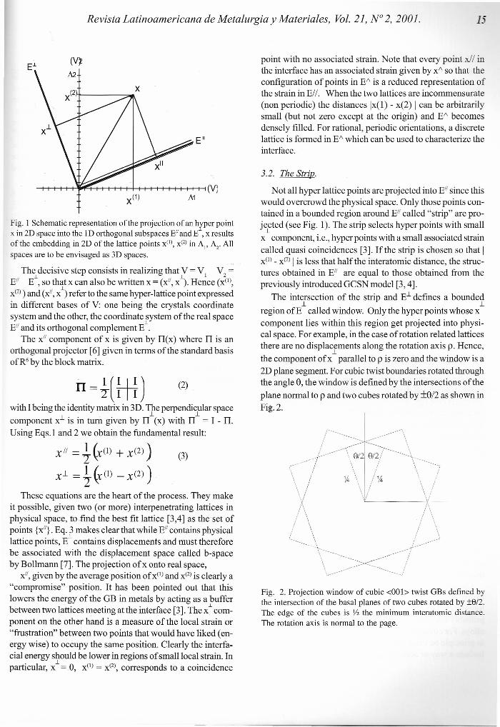
Fig. I Schematic representation of the projection of an hyper pointx in 2D space into the ID orthogonal subspaces EII and E , x resultsofthe embedding in 2D ofthe lattice points x'", X(2) in Al' Az. Allspaces are to be envisaged as 3D spaces.
The decisive step consists in realizing that V = VI V2 =El' EL, so that x can also be written x = (x", x\ Hence (x'",X(2» and (x", x") refer to the same hyper-lattice point expressedin different bases of V: one being the crystals coordinatesystem and the other, the coordinate system ofthe real space. ~E" and its orthogonal complement E .
The x" component of x is given by Il(x) where Tl is anorthogonal projector [6] given in terms ofthe standard basisof'R' by the blockmatrix.
n= i( Hi) (2)
with 1being the identity matrix in 3D.1fe perpendicflar spacecomponent x.l is in tum given by Tl (x) with Il = 1 - Il.Using Eqs.l and 2 we obtain the fundamental result:
x" = ~ (XCI) + x(2) ) (3)
X~ =±~(l) -x(2))
These equations are the heart of the process. They makeit possible, given two (or more) interpenetrating lattices inphysical space, tofind the best fit lattice [3,4] as theset ofpoints {x"}. Eq. 3 makes clear that while E" contains physicallattice points, E~ contains displacements and must thereforebe associated with the displacement space ca11ed b-spaceby Bollmann [7]. The projection ofx onto real space,
x", given by the average position of xCI)and X(2) is clearly a"cornpromise" position. It has been pointed out that thislowers the energy of the GB in metals by acting as a bufferbetween two lattices meeting at the interface [3]. The x~com-ponent on the other hand is a measure of the local strain or"frustration" between two points that would have liked (en-ergy wise) to occupy the same position. Clearly the interfa-cial energy should be lower in regions ofsmall local strain. Inparticular, x.L= .0, x(I) = X(2), corresponds to a coincidence
15
point with no associated strain. Note that every point xiI inthe interface has an associated strain given by x? so that theconfiguration ofpoints in E/\ is a reduced representation ofthe strain in El l. When the two lattices are incommensurate(non periodic) the distances Ix(1) - x(2) I can be arbitrarilysma11 (but not zero except at the origin) and E/\ becomesdensely fi11ed.For rational, periodic orientations, a discretelattice is formed in E/\ which can be used to characterize theinterface.
3.2. The Strip.
Not a11hyper lattice points are projected into E" since thiswould overcrowd the physical space. Only those points con-tained in a bounded region around E" ca11ed"strip" are pro-jected (see Fig. 1). The strip selects hyper points with sma11.1
x component, i.e., hyper points with a small associated strainca11edquasi coincidences [3]. Ifthe strip is chosen so that Ix(I)- X(2) I is less that half the interatomic distance, the struc-tures obtained in E" are equal to those obtained from thepreviously introduced GCSN model [3,4].
The intersection of the strip and E.l defines a bounded.1 .1
region ofE ca11edwindow. Only the hyper points whose xcomponent lies within this region get projected into physi-cal space. For example, in the case of rotation related latticesthere are no displacements along the rotation axis p. Hence,.1
the component ofx para11el to p is zero and the window is a2D plane segment. For cubic twist boundaries rotated throughthe angle e, the window is defmed by the intersections oftheplane normal to p and two cubes rotated by ±e/2 as shown inFig.2.
r-«: I /-.í <, •...••. ~~ /~----/ -v., \,
.-i »>: \\ 8/2 8/2/ '\ .. ".'"".....\" .;/ v l .' '/\ \.\ % \ / %\ í \ /
\/ \1-.I/ \L
\ !\i
/í~.-l/··
Fig. 2. Projection window of cubic <001> twist GBs defined bythe intersection of the basal planes of two cubes rotated by ±812.The edge of the cubes is V2 the minimum interatomic distance.The rotation axis is normal to the page.
16 D. Romeu. /Revista Latinoamericana de Metalurgia y Materiales
The shape of the window depends on the symmetries ofAl and A2' the transformation relating them and to someextent the nature ofthe atomic interactions. Using differentwindow shapes and sizes, it is possible to (crudely) modeldiverse forms of interatomic interactions.
E~
\ I\\ A2 ::'\
'\ ¡i:::' \ \ ->\ \ 'b~."/"\ '.~,\/~<.l"""-;\!'Y' -
'. " '. , ..•...•."'.,." ).;Y::
=oYt~-"%~''-:~¡\;"''"
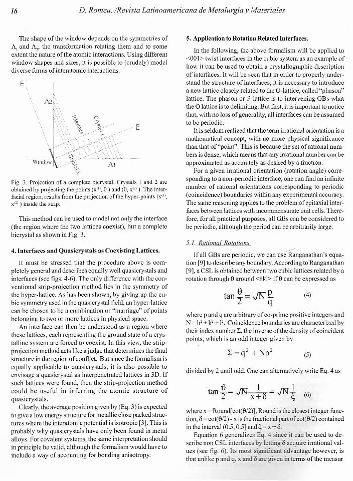
Fig. 3. Projection of a· complete bicrystal. Crystals l and 2 areobtained by projecting the points (x'", °)and (O, X(2) ). The inter-facial region, results from the projection ofthe hyper-points (x'",X(2) ) inside the strip.
This method can be used to model not only the interface(the region where the two lattices coexist), but a completebicrystal as shown in Fig. 3.
4. Interfaces and Quasicrystals as Coexisting Lattices.
It must be stressed that the procedure above is com-pletely general and describes equally well quasicrystals andinterfaces (see figs. 4-6). The only difference with the con-ventional strip-projection method lies in the symmetry ofthe hyper-Iattice. As has been shown, by giving up the cu-bic symmetry used in the quasicrystal field, an hyper-Iatticecan be chosen to be a combination or "marriage" of pointsbelonging to two or more lattices in physical space.
An interface can then be understood as a region wherethese lattices, each representing the ground state of a crys-talline system are forced to coexist. In this view, the strip-projection method acts like a judge that determines the finalstructure in the region of conflict. But since the formalism isequally applicable to quasicrystals, it is also possible toenvisage a quasicrystal as interpenetrated lattices in 3D. Ifsuch lattices were found, then the strip-projection methodcould be useful in inferring the atomic structure ofquasicrystals.
Clearly, the average position given by (Eq. 3) is expectedto give a 10wenergy structure for metallic close packed struc-tures where the interatomic potential is isotropic [3]. This isprobably why quasicrystals have only been found in metalalloys. For covalent systems, the same interpretation shouldin principle be valid, although the formalism would have toinclude a way of accounting for bonding anisotropy.
5. Application to Rotation Related Interfaces.
In the fo11owing, the above formalism will be applied to<001> twist interface s in the cubic system as an example ofhow it can be used to obtain a crystallographic descriptionof interfaces. It will be seen that in order to properly under-stand the structure of interfaces, it is necessary to introducea new lattice closely related to the O-lattice, called "phason"Iattice. The phason or P-lattice is to intervening GBs whatthe O lattice is to delimiting. But first, it is important to noticethat, with no loss of generality, a11interfaces can be assumedto be periodic.
It is seldom realized that the term irrational orientation is amathematical concept, with no more physical significancethan that of"point". This is because the set ofrational num-bers is dense, which means that any irrational number can beapproximated as accurately as desired by a fraction.
For a given irrational orientation (rotation angle) corre-sponding to a non-periodic interface, one can frnd an infinitenumber of rational orientations corresponding to periodic(coincidence) boundaries within any experimental accuracy.The same reasoning applies to the problem of epitaxial inter-faces between lattices with incommensurate unit cells. There-fore, for all practical purposes, a11GBs can be considered tobe periodic, although the period can be arbitrarily large.
5.1. Rational Rotations.»>:
If al! GBs are periodic, we can use Ranganathan's equa-tion [9] to describe any boundary. According to Ranganathan[9], a CSL is obtained between two cubic lattices related by arotation through e around <hkl> if e can be expressed as
tan~= JN~ (4)
where p and q are arbitrary of co-prime positive integers andN =h2 + k2 + F. Coincidence boundaries are characterized bytheir index number L, the inverse ofthe density of coincidentpoints, which is an odd integer given by
(5)
divided by 2 until odd. One can alternatively write Eq. 4 as
t} 1 1tan L = JN."X'+O = -JN~ (6)
where x =Round[ cot(e/2)], Round is the closest integer func-tion, 8 = cot(e/2) - x is the fractional part of cot(e/2) containedin the interval (0.5,0.5] and 1;=x +8.
Equation 6 generalizes Eq. 4 since it can be used to de-scribe non CSL interfaces by letting 8 acquire irrational val-ues (see fig. 6). Its most ignificant advantage however, isthat unlike p and q, x and 8 are given in terms of the measur

Revista Latinoamericana de Metalurgia y Materiales, Vol. 21, N° 2, 2001.
able angle e and are directly related to structural proper-[3]. In terrns of x and 8 the index number L becomes
When 8 is rational, we have a periodic (coincidence) GBand Eq. 6 reduces to Eq. 4. When 8=0 (p=l), ~ =x, and Eq.6becomes:
tan t}x =.JN! (8)2 x
ex marks the position of special singular orientations calleddelimiting. Delimiting boundaries have "special" propertiessuch as minimum dislocation content [3]. In this case ~ = xand
8 is a measure ofthe angular distance of a GB with rotationangle e to the singular orientation ex attained when 8=0 andit is therefore called the deviation parameter.
Note that in Eq.7, the integer p takes part in the definitionof L which makes it ill defined since pis not accessible ex-perimentally. This means that the index number is only welldefrned for delimiting boundaries as given by Eq. 9 where itis unambiguously given in terrns of x which depends on themeasurable angle ex'
Clearly, when the rotation angle is small, x + 8 must belarge so that the fractional part 8 can be neglected in com-parison with x. Therefore, small angle boundaries, which areusually regarded as belonging to a class of their own, be-long to the class of delimiting boundaries.
Delimiting orientations are thus defrned as those for which8 = Oin Eq. 6. Altematively, delimiting boundaries could bedefined as those possessing primary dislocations, i.e., dislo-cations with crystalline Burgers vectors. In contrast, orien-tations for which 8 I O,called intervening [2] contain dislo-cations with non-crystalline Burgers vectors. Accordingly,low angle boundaries should have dislocation networks withcrystalline Burgers vectors in agreement with experimentalevidence.
6. The CrystaUograpby ofInterfaces.
6.1. The O-lattice.
The usefulness ofthe O-lattice resides in that it providesthe dislocation content of interfaces. This however, is onlytrue for delimiting boundaries. It has been known for sometime that intervening GBs near "special" orientations pos-ses a network of so called secondary dislocations [10] with
1
Burgers vectors belonging to the DSC lattice [7]. For suchboundaries, the O-lattice does not describe the dislocation
content, instead, the secondary O-lattice [7] (see below)is used to account for the secondary dislocation network.The problem is that until now no definition of "special" GB(8 = O) had been given, so that the understanding of inter-vening GBs has been incomplete. In fact, all intervening GBs(8 I O) have a network of secondary dislocations with noncrystalline Burgers vectors regardless of their angular dis-tance to the 8 = O"special" orientations.
Burgers vectors of secondary dislocations are of the forrn1-
(X(l) - X(2) )/2 and are thus contained in E (see Eq. 3). Dis-1-
placements in E are known in the quasicrystal jargon asphasons, We shall see that by considering the Phason lat-tice (which contains the secondary O-lattice), it is possibleto fully describe the structure of intervening boundaries.
The O-lattice transforrnation O for rotation related inter-faces is given by the inverse of the displacement field 1-(R<hk1>et1 with I being the identity matrix and R<hk1>e a rota-tion through the angle e around the axis <hkl>. O can beexpressed in several ways depending on the variables interrns ofwhich it is written, the most useful representationsis given in the in median lattice in terrns of~:
o - .Jf7TI( O~- 2 -1 6) (lO)
6.2. CSL and DSC Lattices.
The CSL for <001> twist boundaries can have 2 orienta-tions [3]. One is the "parallel" orientation in which the CSLis given by the O-Iattice rotated by 90° and scaled by 2p. Theother is the inclined orientation in which the CSL is the 0-lattice rotated by 45° and scaled by p.
Since S is only well defined for delimiting GBs we shallconsider the CSL of delimiting boundaries only. In this case,the CSL and O-lattices are parallel when x in Eq. 8 is even andinclined otherwise. Hence, ifwe defrne
F = JIR(OOI)'Tt/4 (11)
andv = 1+ ~2 + 1)nod 2 (12)
where mod is the modulus function we have:
. Where Ox has been obtained from Eq. 10 after making d =O,x=x. Noten=1 for x odd and z otherwise.

·Materiales18 D. Romeu. /Revista Lati1l0'lIlT.!e11to::171!1.
According to Grirmner et al. [11] the DSC lattice transfor-mation D is given by D = (CT)-l where CT is the transpose ofC. Hence, using Eq. 13 we have for delimiting cubic GBs;
D - 1 4 FVQx -YI+"V x
(14)
6.3. P and O Lattices.
According Bollmann, the secondary O-lattice providesthe secondary dislocation network and therefore the struc-ture ofboundaries near "special" orientations at qx. In orderto derive the Secondary O-lattice, Bollmann rightly assumedthat displacements by a vector ofthe DSC lattice (D) ofthenearby "special" orientation which we now know is at ex'should preserve the structure ofthe interface and conc1udedthat secondary dislocations should have Burgers vectorsbelonging to Dx. Following Bollmann, the secondary O-lat-tice of an intervening GB at e = e· + ~e is given by S, = o D
x ~ '1' x(see Eq. 10, 14), with \jf being the value of ~ resulting fromsubstituting ~e = e - ex in Eq. 6. S~is thus given in the medianlattice by:
1 ( OS~=20.JX+T~ -1 (15)
Eq .15 can be expressed in terrns of the structure matrix ofthe intervening O-lattice O~at e as:
In other words, the secondary O-lattice can be obtainedapplying p2-v to the conventional O-lattice scaled by theinverse of the deviation parameter, a far simpler operationthan calculating O and D . We now see the convenience of'V xthe notation introduced in section 5. The Secondary 0-lattice vectors, marked with thin arrows in Fig. 5 join inter-vening domains of the same type while the P-Iattice joinsdomains of different type. The P-Iattice is given, in terrns ofthe O-lattice, by
P~= F2(I-v) (8-10~) (17)
Finally, using Eqs 16 and 17 we have:
Clearly, O and thus S~and P~diverge for delirniting bound-aries. Note alllattices can be expressed in terrns ofthe inter-vening O-lattice and the deviation parameter.
U:rst:allil:lgl'2Ilh;:y ofTwíst Grain Boundaries.
-ef description of the result of applyingtbe Sü"~~~:lHRl furrnalis:m to <001> twist boundaries inthe be given. For reasons of space, onlythe main '" eamres will be described with no de-tailed Cf\ - anal sis such as the symmetry ofthedomains. Ho :eL ir should be clear to the reader that suchanaly is folIo ightforwardly from the data given.
7.1. Delimitinf! Boundaries.
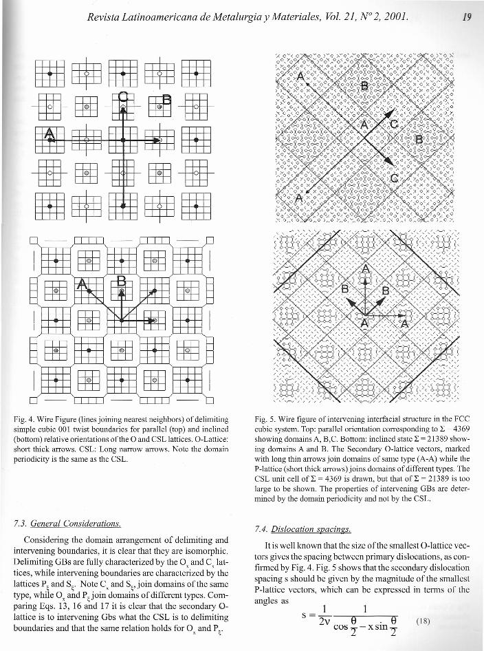
The interface of <001> delimiting GBs consists of asingle plane (in contrast to the <011> case where it can bestepped [4]) of atomic domains that have the structure of a001 crystal plane (a quare pattem corresponding to S = 1;q = O). Delimiting domains are separated by a network ofprimary dislocations. An example of delimiting boundariesfor the two possible orientations is shown in Fig 4. Alldelimiting GBs have the same structure,and differonly inthe size of the domains, which decreases with qx.Althoughall domains have the same structure, they differ in the rela-tive displacement of their centers with respect to the 0-point at their center. Domains labeled A, B and C, with 0-points colored black, gray and white are shifted by thevectors with coordinates {O,O}, Y2{ 1,1} and Y2{ 0,1} respec-tívely, given in terms of the unít vectors of the median lattice.
The inclined orientation has O-points of types A and Bonly, while the parallel orientation also has domains typeC. Thick vectors indicate the O-lattice and thin long arrowsrepresent the CSL unit vectors. Note the CSL coincides withthe sublattice defined by O-points type A.
7.2. Intervening Boundaries.
Intervening interfaces are also composed of domains, buthere they do not have the same structure. Domains in GBswith ~ in the interval (x - O, x + o) have different symmetriescorresponding to the translational states [12] of the associ-ated delimiting boundary at the center of the interval (0=0)[3]. Intervening domains are separated by a network of (par-tíal). secondary dislocations. Domain size (and hence sec-ondary dislocation spacing) increases as ~-7X,(0-70). Inthe limit 8 = O, the GB becomes delimitíng and the domainsize and secondary dislocation spacings diverge, inaccordance with experimental observations [10].
Fig. 5 shows that just as for delimiting boundaries, theinclined orientation contains two types of domains A andB, while the parallel orientation has an additional type C.Domains type A, B and C are also with respect tothe centralPvlattice point by with-coordi-nates {O,O}, V2fl,l} and l_{
It should be noted 1b<!!II!:r¡:".::!::;z:::::¡ ~!::::"i!mgem.entin delim-iting and interv e _The differencebeing that . given by the P-lattice, while e O-lattice.
Revista Latinoamericana de Metalurgia y Materiales, Vol. 21, N° 2,2001.
--- -- ---
I 00 00 II I I I- g
~ ~
- 00 00-
" ;r-
1<, V-
I 00<, v Ir-, ./
II I- -- 00 00 00 -- -- -- -
I 00 00 II
Fig. 4. Wire Figure (linesjoining nearest neighbors) of delimitingsimple cubic 001 twist boundaries for parallel (top) and inclined(bottom) relative orientations ofthe O and CSL lattices. O-Lattice:short thick arrows. CSL: Long narrow arrows. Note the domainperiodicity is the same as the CSL.
7.3. General Considerations.
Considering the domain arrangement of delimiting andintervening boundaries, it is clear that they are isomorphic.Delimiting GBs are fully characterized by the 0x and ex lat-tices, while intervening boundaries are characterized by thelattices P~and S~. Note ex and S~,join domains ofthe sametype, while 0x and P~join domains of different types. Com-paring Eqs. 13, 16 and 17 it is clear that the secondary 0-lattice is to intervening Gbs what the eSL is to delimitingboundaries and that the same relation holds for 0x and P~.
19
Fig. 5. Wire figure of intervening interfacial structure in the FCCcubic system. Top: parallel orientation corresponding to L = 4369showing domainsA, B,C. Bottom: inclined state L = 21389 show-ing domains A and B. The Secondary O-Iattice vectors, markedwith long thin arrows join domains of same type (A-A) while theP-lattice (short thick arrows) joins domains of different types. TheCSL unit cell oLE = 4369 is drawn, but that of L = 21389 is toolarge to be shown. The properties of intervening GBs are deter-mined by the domain periodicity and not by the CSL.
7.4. Dislocation spacings.
It is well known that the size ofthe smallest O-lattice vec-tors gives the spacing between primary dislocations, as con-firrned by Fig. 4. Fig. 5 shows that the secondary dislocationspacing s should be given by the magnitude of the smallestP-lattice vectors, which can be expressed in terrns of theangles as
1 1s-- 2v e . ecos 2"-XSln2
(18)
20 D. Romeu. /Revista Latinoamericana de Metalurgia y Materiales
and letting L18= 8 - 8x we obtain:
. exl·sm-
s= 22v . ~esm-
2
(19)
which are in agreement with experimental observations [3,10]and support the conclusion of section 7-3.
8. Structure vs. Properties.
The properties of both intervening and delimiting GBsdepend on the period and structure of domains, and not onthe period ofthe CSL, except for delimiting boundaries wherethe domain and CSL periods coincide.
This is a straightforward conclusion since as we haveseen, even an infinitesimal variation in the misorientationangle 8, can greatly change the periodicity ofthe GB. Theperiod of the domain structure as evidenced by measure-ments of dislocation spacings on the other hand, variessmoothly with the angle. We therefore see that the coinci-dence lattice concept is only useful for delimiting bound-aries.
Burgers vectors can be determined by applying the Frank-Bilby equation to Eqs. 10 and 16. Primary dislocations havea crystalline Burgers vector of the form xCi), entirely con-tained in the physical space EII, and their spacing is given bythe size ofthe smallest O-lattice vectors (Eq. 10). The dis-placement associated to secondary dislocations on the otherhand is of the form o (x'" - X(2)) which is contained in theperpendicular space E.l (see Eq. 3) and their spacing is givenby the size ofthe smallest P-lattice vectors (Eq. 16).
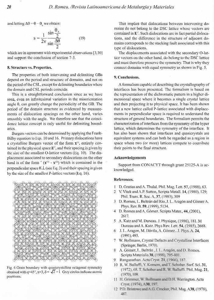
Fig. 6 Grain boundary with quasicrystalline octagonal syrnrnetryobtainedwith q=450, x=3, 8= -tI -1 Greycircles indicate atomicpositions.
This implies that dislocations between intervening do-mains do not belong to the DSC lattice whose vectors arecontained in EII. Such dislocations are in fact partial disloca-tions, and the difference in the structure of adjacent do-mains corresponds to the stacking fault associated with thistype of dislocations.
The displacements associated with the secondary O-lat-tice vectors on the other hand, do belong to the DSC latticeand must therefore preserve the symmetry. That is why theyconnect domains with equal symmetry as shown in Fig. 5.
9. Conclusions.
A formalism capable of describing the crystallography ofinterfaces has been presented. The formalism is based onthe representation ofthe dichromatic pattem in a higher di-mensional space where it becomes a single crystal latticeand then projecting it to physical space. It has been shownthat a new lattice called P-lattice associated with displace-ments in perpendicular space is required to understand thestructure of general boundaries. The formalism permits thecharacterization of interfaces from the symmetry ofthe hyperlattice, which determines the symmetry ofthe interface. Ithas also been shown that interfaces and quasicrystals areequivalent systems and can both be regarded as a region inspace where two (or more) lattices compete to contributetheir points to the final structure.
Acknowledgements
Support from CONACYT through grant 25125-A is ac-knowledged.
References.
1 D. Gratias andA. Thalal. Phil. Mag. Lett. 57, (1988), 63.2 V. VitekandA.P. Sutton, Scripta Metall. 14, (1980),129;
Phil. Trans. R. SocoA, 37, (1983), 3093 D. Romeu, L. Beltrán del Río, J. L. Aragón and Gómez A.
Phys. Rey. B. 59, (1999), 5134.4 D. RomeuandA. Gómez. ScriptaMater., 44, (2001),
2617.5 A. Katz and M. Duneau. J. Physique, (1986), 181. M
Duneau andA. Katz. Phys Rey. Lett. 54, (1985), 2688.6 J. L. Aragon, M. Dávila, A. Gómez .. J. Phys. A. 24,
(1991),493.7 W. Bollmann, Crystal Defects and Crystalline Interfaces
(Springer, Berlin, 1970).8 A. Gómez, L. Beltrán , J. L. Aragón, and D. Romeu.
Scripta Materialia 38 (1998), 95-801.9 Ranganathan. Acta Cry 21. 1966), 187.10 R. W. Balluffi, Y.Komem. andT. Schober. Surf. Sci. 31,
(1972),68. T. R.. . Balluffi. Phil. Mag. 21,(1970), 109.
11 H. GtinuIIoc - DlI. Warrington. Actae 1 -
L nn, er, Phi1.Mag. A38, (1978),