D-Link xStack Storage iSCSI SAN Array
38
D-Link xStack Storage iSCSI SAN Array Managed SAN Solution DSN-4100, DSN-4200 and DSN-4000 Hardware Reference Guide Version 1.0 xStack Storage TM
Transcript of D-Link xStack Storage iSCSI SAN Array

D-Link xStack Storage iSCSI SAN Array Managed SAN Solution
DSN-4100, DSN-4200 and DSN-4000
Hardware Reference Guide
Version 1.0
xStack Storage TM

ii

Copyright
D-Link Systems, Inc. makes no warranty of any kind with regard to this material, including,
but not limited to, the implied warranties of merchantability and fitness for a particular
purpose. D-Link Systems, Inc. shall not be liable for errors contained herein or for incidental
or consequential damages in connection with the furnishing, performance, or use of this
material.
This document contains proprietary information, which is protected by copyright. No part of
this document may be photocopied, reproduced, or translated into another language without
the prior written consent of D-Link Systems, Inc.
The information is provided “as is” without warranty of any kind and is subject to change
without notice. The only warranties for D-Link products and services are set forth in the
express warranty statements accompanying such products and services. Nothing herein
should be construed as constituting an additional warranty. D-Link shall not be liable for
technical or editorial errors or omissions contained herein.
Copyright © 2011 D-Link Systems, Inc. ™; All Tights Reserved
Patents and Trademarks
Includes one or more of the following United States patents: 6,941,396; 7,353,306; 7,389,462; 7,460,473; 7,512,663 and 7,594,002. Other patents are pending.
D-Link and the D-Link logo are registered in U.S. Patent and Trademark Office. All other product names mentioned herein may be trademarks or registered trademarks of their respective companies.
Microsoft Windows is a U.S. registered trademark of Microsoft Corporation.
All other brand or product names are or may be trademarks or service marks, and are used to identify products or services, of their respective owners.
Important data protection information
You should back up all data before installing any drive controller or storage peripheral. D-Link is not responsible for any loss of data resulting from the use, disuse or misuse of this or any other D-Link product.
Notice and Recommendations
Although D-Link has attempted to ensure the accuracy of the content of this manual, it is possible that this document may contain technical inaccuracies, typographical, or other errors. D-Link provides this publication “as is” without warranty of any kind, either express or implied, including, but not limited to implied warranties of merchantability or fitness for a particular purpose.
D-Link assumes no liability for any error in this publication, and for damages, whether direct, indirect, incidental, consequential or otherwise, that may result from such error, including, but not limited to loss of data or profits. The published information in the manual is subject to change without notice. D-Link reserves the right to make changes in the product design, layout, and driver revisions without notification to its users.
This version of this manual supersedes all previous versions.

iv Contents
Safety Information
This product uses a lithium coin cell battery. The lithium coin cell battery is a long-life
battery, and it is very possible that you will never need to replace it. However, should you
need to replace it, please consult your service documentation.
There is a danger of a new battery exploding if it is incorrectly installed.
Replace the battery pack only with the same or equivalent type recommended
by the manufacturer. Do not dispose of the battery along with household waste.
Contact your local waste disposal agency for the address of the nearest battery
disposal site.
CAUTION
RISK OF EXPLOSION IF BATTERY IS REPLACED BY AN INCORRECT TYPE. DISPOSE OF USED BATTERIES ACCORDING TO THE INSTRUCTIONS.
Notice of Export Controls
Export of technical data contained in this document may require an export license from the
United States government. Please contact D-Link, Inc. for any export compliance questions.
Document Revision Level
Revision Date Description
1.0 August 24, 2011 Initial release.

DSN-4000 Series Hardware Reference Guide v
Preface
This document is intended to assist users with installing the primary array and expansion
array of the xStack Storage DSN-4000 Series storage system from D-Link, Inc. This document
assumes that users are computer literate, familiar with storage array products, and have a
basic understanding of storage products and concepts. Throughout this document, the term
“DSN-4000 series” or “DSN-4X00” refers to all of the members of the DSN-4000 Series
product family, whereas a reference to a specific model will appear as DSN-4100, DSN-4200
or DSN-4000. For clarity, some illustrations may only show the DSN-4200 enclosure, but the
concepts are applicable to all models.
Typographic Conventions
Notes
Notes provide information that deserves special attention. They are preceded by:
Cautions
Cautions contain information which, if not followed, can cause damage to the
storage system and possible loss of data. They are preceded by:
Warnings
Warnings contain information which, if not followed, can cause damage to the
storage system and to the person installing it. They are preceded by:
Related Documentation
In addition to this document, the following documents are available from D-Link.
� xStack Storage Management Center Software User's Guide. This guide provides the
information needed to configure and manage storage on the xStack Storage system using
the xStack graphical user interface.
vi Contents
Contact Information
You can find software updates and user documentation on the D-Link website.
D-Link provides free technical support for customers within the United States and within
Canada for the duration of the warranty period on this product.
U.S. and Canadian customers can contact D-Link Technical Support through our website, or
by phone.
Tech Support for customers within the United States: D-Link Technical Support over the Telephone Please see our support site for current number:
• http://support.dlink.com
• Monday to Friday 8:00am – 5:00pm PST/PDT D-Link Technical Support over the Internet:
• http://support.dlink.com Tech Support for customers within Canada: D-Link Technical Support over the Telephone Please see our support site for current number:
• http://support.dlink.ca
• Monday to Friday 7:30am to 9:00pm EST/EDT D-Link Technical Support over the Internet:
� http://support.dlink.ca

DSN-4000 Series Hardware Reference Guide vii
Contents
Chapter 1 Introduction ............................................................................................................................ 1
1.1 Models ............................................................................................... 1
1.2 Features and Benefits ............................................................................. 2
1.3 System Overview ................................................................................... 2
Chapter 2 DSN-4000 Series Primary Array Layout ............................................................................... 3
2.1 Front Panel Components ......................................................................... 4
2.2 Rear Panel Components .......................................................................... 6
2.3 Side, Top and Bottom Panel Components ..................................................... 9
Chapter 3 Installing the DSN-4X00 Primary Array .............................................................................. 11
3.1 Site Considerations ............................................................................... 12
3.1.1 General Considerations .................................................................. 12
3.1.2 Desktop or Shelf Installation ............................................................ 12
3.1.3 Rack-mount Guidelines ................................................................... 13
3.2 Safety Considerations ............................................................................ 13
3.3 Unpacking the DSN-4X00 Primary Array ....................................................... 14
3.4 Items Supplied by the User ..................................................................... 14
3.5 Installing the Hard Disk Drives .................................................................. 15
3.6 Connecting to the iSCSI Data Ports ............................................................ 16
3.7 Connecting to the Management Port .......................................................... 16
3.8 Connecting the AC Power Cords ................................................................ 18
3.9 Connect any DSN-4000 JBOD Expansion Arrays (optional) ................................. 18
3.10 Powering-on the DSN-4000 JBOD Expansion Arrays ......................................... 19
3.11 Powering-on the DSN-4X00 Storage Array .................................................... 20
3.12 Hot-Plugging Additional DSN-4000 JBOD Expansion Arrays ................................ 20
Appendix A Replacing and Upgrading FRUs ......................................................................................... 21
A.1 Installing or Removing Hard Disk Drives ...................................................... 22
A.2 Replacing a Power Supply Module ............................................................. 23
A.3 Replacing a Cooling Fan Module ................................................................ 24
A.4 Replacing the Controller Module in the Primary Array ..................................... 25
A.5 Replacing the Cache Battery Backup Module ................................................ 26
A.6 Connecting to the Diagnostic Serial Port ..................................................... 27
Appendix B Installing the System in a Rack .......................................................................................... 29

viii Contents
This page intentionally left blank.

DSN-4000 Series Hardware Reference Guide 1
Chapter 1 Introduction
The xStack Storage DSN-4000 series storage system is an intelligent, high-performance
multiple Gigabit Ethernet storage solution designed for businesses that want to improve the
reliability, availability, serviceability, and performance of their storage systems. It provides
a range of benefits and features from its ability to use familiar, proven, and widespread
networking technologies like IP and Ethernet for storage solutions.
The DSN-4000 series storage system is highly scalable. To add more storage capacity, simply
add additional DSN-4000 expansion arrays to the DSN-4X00 primary array for up to 80 drives.
This plug-and-play approach to storage expansion enables you to form a scalable enterprise
storage grid of many drives quickly and easily.
Based on an Internet Protocol-Storage Area Network (IP-SAN) architecture, the DSN-4X00
primary array is built around D-Link’s iSCSI RAID processor system-on-a-chip and has the
following features:
� Up to 80 Serial Attached SCSI (SAS) or Serial Advanced Technical Attachment (SATA) hard
disk drives per system (including DSN-4000 expansion arrays), with a maximum storage
capacity of 2TB per drive
� A minimum of 512 MB of System Memory, expandable to 2GB
� A minimum of 1024 MB of Buffer Memory, expandable to 4 GB
� iSCSI Ethernet Connectors (depending on your specific hardware configuration):
� Eight 1-Gigabit RJ-45 connectors
� Four 1-Gigabit RJ-45 connectors
� A 10/100/1000 Mbps Ethernet management port
� One SAS expansion connector for attaching additional DSN-4000 JBOD expansion arrays
� One 3.5mm RS-232-C stereo mini-jack diagnostic port for troubleshooting purposes
Complete configuration and management of the storage system are available through the
intuitive, graphical-based Management Center software.
1.1 Models
The D-Link xStack Storage DSN-4000 series storage array is available in various models. The
models differ according to the speed and host network interface, as well as the number of
drive bays. Table 1-1 lists the various DSN-4X00 Primary Array models.
Table 1-1. DSN-4X00 Primary Array Models
Model
Drive Bays
iSCSI Data Ports
iSCSI Data Port Speed
DSN-4200 16 Eight RJ-45 ports 1 Gigabit per second
DSN-4100 16 Four RJ-45 ports 1 Gigabit per second

2 Chapter 1 Introduction
1.2 Features and Benefits
� High-performance, low-latency iSCSI storage system, with a highly integrated multifunction ASIC for fully featured, integrated storage virtualization
� Modular design with the ability to add hot-swappable DSN-4000 expansion arrays for up to 80 drives, with each drive having a maximum storage capacity of up to 2TB
� Easy setup and configuration – can be installed anywhere on a 1-Gigabit Ethernet network for improved access to critical information
� In-band or out-of-band management via direct connection or the Web
� Delivers Ethernet economics to storage for lower total cost of ownership and rapid deployment using known and trusted technologies
� Proven transport infrastructure for increased reliability, investment protection, and reduced training and administrative costs
� Scalability over long distances - ideal for remote data replication and disaster recovery
� High availability - redundant cooling fans and 2 redundant, hot-swappable, auto-sensing, load-sharing power supplies
� Intelligent battery pack ensures that a charged battery is on hand to preserve buffer cache contents if a power failure occurs. Contents are backed up for approximately 72 hours with the standard 2GB data cache (48 hours with the 4GB data cache option).
1.3 System Overview
Figure 1-1 shows a typical DSN-4X00 storage system configuration in a Storage Area Network
(SAN). The SAN shown is an Ethernet network used solely for exchanging data between the
customer's host servers and the DSN-4000 series array. The Ethernet bandwidth used by the
servers exchanging data with the storage system can be very high. Using a separate
Ethernet to act as a SAN keeps that data from interfering with the customer's existing LAN
and improves security.
Figure 1-1. Example of a DSN-4000 Series Storage System Configuration
DSN-4000 Series Hardware Reference Guide 3
Chapter 2 DSN-4000 Series Primary Array Layout
This chapter describes the hardware components on the DSN-4X00 primary array. The topics
covered in this chapter are:
� Section 2.1, Front Panel Components
� Section 2.2, Rear Panel Components
� Section 2.3, Side, Top and Bottom Panel Components
4 Chapter 2 VessRAID 1836i/1846i Series Primary Array Layout
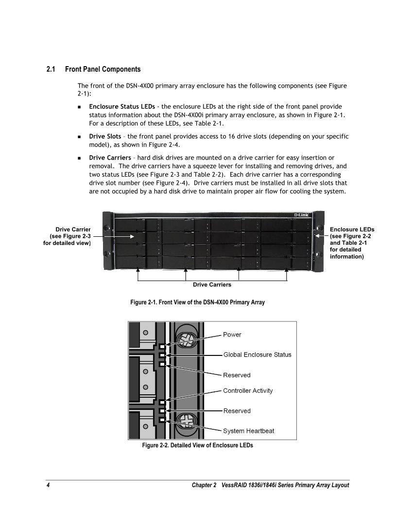
2.1 Front Panel Components
The front of the DSN-4X00 primary array enclosure has the following components (see Figure
2-1):
� Enclosure Status LEDs - the enclosure LEDs at the right side of the front panel provide
status information about the DSN-4X00i primary array enclosure, as shown in Figure 2-1.
For a description of these LEDs, see Table 2-1.
� Drive Slots – the front panel provides access to 16 drive slots (depending on your specific
model), as shown in Figure 2-4.
� Drive Carriers – hard disk drives are mounted on a drive carrier for easy insertion or
removal. The drive carriers have a squeeze lever for installing and removing drives, and
two status LEDs (see Figure 2-3 and Table 2-2). Each drive carrier has a corresponding
drive slot number (see Figure 2-4). Drive carriers must be installed in all drive slots that
are not occupied by a hard disk drive to maintain proper air flow for cooling the system.
Figure 2-1. Front View of the DSN-4X00 Primary Array
Figure 2-2. Detailed View of Enclosure LEDs
Enclosure LEDs (see Figure 2-2 and Table 2-1 for detailed
information)
Drive Carriers
Drive Carrier (see Figure 2-3
for detailed view)

DSN-4000 Series Hardware Reference Guide 5
Table 2-1. Enclosure LEDs
LED Description
Power Green: Indicates that the primary array is powered on.
Global Enclosure Status Green: Indicates that the primary array is powered on and functioning.
Red: Indicates that a fault condition exists and requires user attention
Controller Activity Flashing Green: Indicates that there is system activity
System Heartbeat Flashing Green: While the system is operating normally, this LED blinks seven (7) times, then turns off for approximately 4 seconds, then repeats with a total cycle time of 8 seconds
Figure 2-3. Detailed View of the Drive Carrier
Table 2-2. Drive Carrier Status LEDs
LED Description
Disk Status Off: No hard disk is present.
Green: The hard disk is powered on and available.
Red: The hard disk has failed and should be replaced.
Power/Activity Off: The disk is idle or no disk is present.
Flashing Green: A hard disk is present and there is disk activity.
Figure 2-4. Drive Slot Numbers on the DSN-4X00 Primary Array
6 Chapter 2 VessRAID 1836i/1846i Series Primary Array Layout
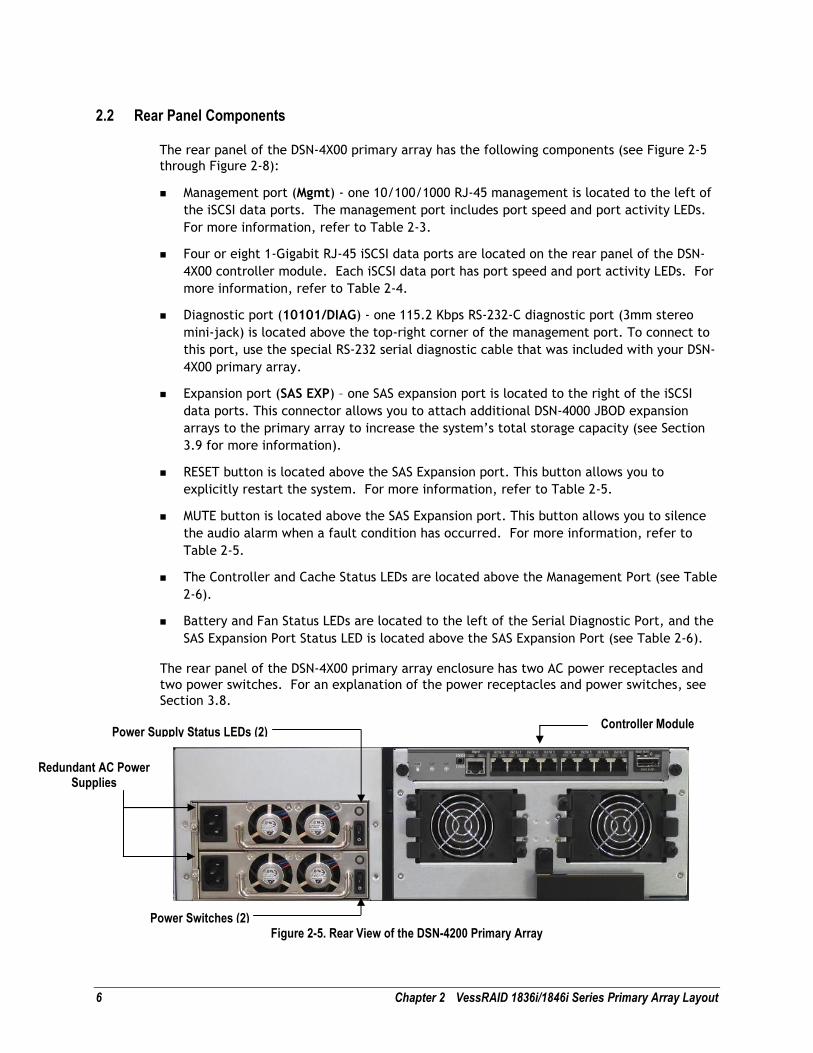
2.2 Rear Panel Components
The rear panel of the DSN-4X00 primary array has the following components (see Figure 2-5
through Figure 2-8):
� Management port (Mgmt) - one 10/100/1000 RJ-45 management is located to the left of
the iSCSI data ports. The management port includes port speed and port activity LEDs.
For more information, refer to Table 2-3.
� Four or eight 1-Gigabit RJ-45 iSCSI data ports are located on the rear panel of the DSN-
4X00 controller module. Each iSCSI data port has port speed and port activity LEDs. For
more information, refer to Table 2-4.
� Diagnostic port (10101/DIAG) - one 115.2 Kbps RS-232-C diagnostic port (3mm stereo
mini-jack) is located above the top-right corner of the management port. To connect to
this port, use the special RS-232 serial diagnostic cable that was included with your DSN-
4X00 primary array.
� Expansion port (SAS EXP) – one SAS expansion port is located to the right of the iSCSI
data ports. This connector allows you to attach additional DSN-4000 JBOD expansion
arrays to the primary array to increase the system’s total storage capacity (see Section
3.9 for more information).
� RESET button is located above the SAS Expansion port. This button allows you to
explicitly restart the system. For more information, refer to Table 2-5.
� MUTE button is located above the SAS Expansion port. This button allows you to silence
the audio alarm when a fault condition has occurred. For more information, refer to
Table 2-5.
� The Controller and Cache Status LEDs are located above the Management Port (see Table
2-6).
� Battery and Fan Status LEDs are located to the left of the Serial Diagnostic Port, and the
SAS Expansion Port Status LED is located above the SAS Expansion Port (see Table 2-6).
The rear panel of the DSN-4X00 primary array enclosure has two AC power receptacles and
two power switches. For an explanation of the power receptacles and power switches, see
Section 3.8.
Figure 2-5. Rear View of the DSN-4200 Primary Array
Controller Module
Redundant AC Power Supplies
Power Switches (2)
Power Supply Status LEDs (2)

DSN-4000 Series Hardware Reference Guide 7
Figure 2-6. Detailed View of the DSN-4200 Controller Module
Figure 2-7. Detailed View of 8-port DSN-4200 Controller Rear Panel
Figure 2-8. Detailed View of 4-port DSN-4100 Controller Rear Panel
Table 2-3. Management Port LEDs
LED Description
Port Activity Flashing Amber: Data is being sent or received
Off: No data is being sent or received
Link Speed Green: Network link is operating at 1000 Mbps
Red: Network link is operating at 100 Mbps
Off: No network link is detected
Reset Button
Mute Audio Alarm Button
Battery and Fan Status LEDs
Dirty Cache LED Management Port
Controller Status LED
RS-232 Serial Diagnostic Port
Hot-Swappable Fan Module
Hot-Swappable Fan Module
Ejection Lever
SAS Expansion
Port
iSCSI Data Ports and Status LEDs
SAS Expansion Port Status

8 Chapter 2 VessRAID 1836i/1846i Series Primary Array Layout
Table 2-4. 1-Gigabit iSCSI Data Port LEDs
LED Description
Port Activity Flashing Green: Data is being sent or received
Off: No data is being sent or received
Link Speed Green: Network link is operating at 1000 Mbps
Amber: Network link is operating at 100 Mbps
Off: No network link is detected
Table 2-5. Rear Panel Buttons and Switches
Switch or Button Description
Power Turns on the power to the DSN-4X00 primary array. There are two power switches, and both switches must be turned on.
RESET Resets the system. This switch is recessed to prevent accidental resets, which could cause loss of data.
MUTE Mutes the audio alarm when a fault condition has occurred. Refer to Table 2-7 for a list of fault conditions that will cause the audio alarm to sound.
Table 2-6. Rear Panel LEDs
Icon Description LED Conditions
Controller Status
Green: The controller is operating normally.
Red: The controller encountered a failure condition that requires some corrective action
Off: The controller is powered-off or not ready.
Dirty Cache Flashing Green: The battery is maintaining cache memory when the system is powered off or when a system fault condition has occurred.
Off: The cache memory is functioning normally.
Battery Status Solid Green: The battery is present and fully charged.
Flashing Green: The battery is charging.
Solid Red: The battery is failed or not present.
Off: The system is powered-off or not ready.
Cooling Fan Status
(one for each fan module)
Green: The fan is running properly.
Red: The fan has failed or is missing, and should be replaced as soon as possible.
Off: Unknown fan status.
None SAS Expansion Port Status
Flashing Green: There is activity on the SAS Expansion Port.
Off: The SAS Expansion Port is not active.
None Power Supply Status
Green: The power supply module is powered-on and functioning correctly.
Amber or Red: The power supply module has failed.
Off: The power supply module is powered-off or the AC power cord is disconnected.

DSN-4000 Series Hardware Reference Guide 9
Table 2-7. Failure Conditions that Activate the System Fault LED and Audio Alarm
Failure Condition Description and Additional Information
Power Supply Failure The Global Enclosure Status LED and Controller Status LED will be illuminated in red and the audio alarm will sound.
Cooling Fan Failure The Global Enclosure Status LED and Controller Status LED will be illuminated in red and the audio alarm will sound.
Battery Failure The Global Enclosure Status LED and Controller Status LED will be illuminated in red and the audio alarm will sound. A system shutdown and restart are required after the failed battery has been replaced.
Over Temperature The Global Enclosure Status LED and Controller Status LED will be illuminated in red and the audio alarm will sound.
Software Failure The Global Enclosure Status LED and Controller Status LED will be illuminated in red and the audio alarm will sound.
2.3 Side, Top and Bottom Panel Components
The left and right sides of the DSN-4X00 enclosure do not require any special hardware for
rack-mounting the unit. Instead the enclosure simply slides into the rails that are supplied
with the system. Product information and regulatory agency labels can be found on the top
surface of the unit. For rack-mount instructions, refer to Appendix B and the documentation
for your rack.

10 Chapter 2 VessRAID 1836i/1846i Series Primary Array Layout
This page intentionally left blank.

DSN-4000 Series Hardware Reference Guide 11
Chapter 3 Installing the DSN-4X00 Primary Array
This chapter describes how to install the DSN-4X00 primary array. The topics covered in this
chapter are:
� Section 3.1, Site Considerations
� Section 3.2, Safety Considerations
� Section 3.3, Unpacking the DSN-4X00 Primary Array
� Section 3.4, Items Supplied by the User
� Section 3.5, Installing the Hard Disk Drives
� Section 3.6, Connecting to the iSCSI Data Ports
� Section 3.7, Connecting to the Management Port
� Section 3.8, Connecting the AC Power Cords
� Section 3.9, Connect any DSN-4000 JBOD Expansion Arrays (optional)
� Section 3.10, Powering-on the DSN-4000 JBOD Expansion Arrays
� Section 3.11, Powering-on the DSN-4X00 Storage Array
12 Chapter 3 Installing the DSN-4000 Series PrimaryArray
3.1 Site Considerations
The site where you install the DSN-4X00 storage array can affect its performance. Therefore,
choose a site that conforms to the requirements in the following sections.
3.1.1 General Considerations
Observe the following considerations when selecting a location to install the DSN-4X00
storage array.
� The location should be fairly cool and dry for the acceptable temperature and humidity
ranges.
� The location should be free of strong electromagnetic field generators (such as motors),
vibration, dust, and direct exposure to sunlight.
� The location must provide sufficient airflow to the front and back of the DSN-4X00
storage array for correct cooling. Ventilation must be sufficient to exhaust heat from the
rear of the equipment.
� The location should offer two AC power outlets within six feet (1.82 meters) of the DSN-
4X00 storage array. Ideally, the two power outlets should be on separate circuits for
optimum power redundancy.
� The location should allow for at least six inches (15.2 cm) of space at the front and back
of the DSN-4X00 storage array for ventilation.
� Do not place the DSN-4X00 storage array next to, on top off, or below any device that
generates a significant amount of heat or will block the free flow of air through the DSN-
4X00 storage array ventilation slots.
3.1.2 Desktop or Shelf Installation
The DSN-4X00 storage array can be mounted on a desktop or shelf. Observe the following
considerations for desktop or shelf installations.
� Select a sturdy, level surface that can support the DSN-4X00 storage array. A fully
populated unit weighs approximately 35 pounds (15.8 kg) with 16 drives or 28 pounds
(12.6 kg) with 12 drives (assuming 1.1 pound / 0.5 kg per drive).
� Allow enough ventilation space between the DSN-4X00 storage array and any other
objects in the vicinity.
� Be sure not to block the air vents on the front and back of the DSN-4X00 storage array
enclosure. Install the cables and power cords according to the procedures in the
following sections.

DSN-4000 Series Hardware Reference Guide 13
3.1.3 Rack-mount Guidelines
The DSN-4X00 storage array can be mounted in a standard 19-inch rack. Observe the
following considerations for rack installations. For information about installing the system in
a rack, refer to Appendix B and to the documentation for the rack.
� All rack-mounting hardware must be carefully assembled to properly support the
equipment. Follow the instructions in the documentation for the rack.
� The operating ambient temperature of rack-mounted equipment must not exceed the
maximum rated ambient temperature indicated in this guide.
� The rack cabinet must provide sufficient airflow to the front and back of the DSN-4X00
storage array to maintain correct cooling. It must include ventilation sufficient to
exhaust the heat generated by equipment installed in the rack.
� The rack must allow enough ventilation space between the DSN-4X00 storage array and
any other objects in the vicinity. Do not block the air vents on the front and back of the
DSN-4X00 storage array enclosure. The air flow clearances specified in this guide must
be maintained within the rack.
� The AC supply circuit for rack-mounted equipment must be capable of supplying the
total current specified on all the labels of the rack-mounted equipment.
� All AC power supply connections must be properly grounded. To ensure the integrity of
the earth connection, special attention must be given to connections that are not
directly connected to the branch circuit (for example, power strips).
� If additional DSN-4000 JBOD expansion arrays will be added, leave sufficient space in the
rack for those arrays, since the cables supplied for connections between the DSN-4X00
primary array and the DSN-4000 JBOD expansion arrays or between additional expansion
arrays require that all arrays be in close proximity to each other.
3.2 Safety Considerations
Observe the following guidelines to ensure safety:
� Do not wear loose clothing that could get caught in the chassis mounting hardware.
� Wear safety glasses when working under conditions that are hazardous to your eyes.
� Do not perform any action that creates a potential hazard to people or makes the rack
or equipment unsafe.
� Do not work on the equipment or disconnect cables during a thunderstorm, when
wearing a wool sweater or other heavy wool clothing, or when power is applied.
� Disconnect all power before installation and before connecting or disconnecting cables.
� Avoid hazards such as moist floor and ungrounded power-extension cables.
� To avoid damage to the DSN-4X00 storage array due to Electrostatic discharge (ESD), you
should wear an ESD-preventive wrist strap when working on the array. Connect the clip
to an unpainted surface of the chassis frame to safely channel unwanted ESD voltages to
ground. If no wrist strap is available, ground yourself by touching the metal part of the
chassis.

14 Chapter 3 Installing the DSN-4000 Series PrimaryArray
3.3 Unpacking the DSN-4X00 Primary Array
After receiving the DSN-4X00 storage array, perform the following steps to ensure that the
storage array and other contents arrived safely.
1. Inspect the outer shipping carton for any damage that may have occurred in shipping.
Report any sign of damage to the appropriate shipping agency.
2. Remove the DSN-4X00 storage array and cables from the shipping carton.
3. Save the shipping container, foam, and antistatic bags in case you have to return the
DSN-4X00 storage array. Returning the storage array in any other container is not
recommended.
4. Check the contents against the items referenced on the packing list. If any item is
missing or damaged, notify a sales representative and/or the shipping agency.
3.4 Items Supplied by the User
Table 3-1 lists the additional items you must supply to install the DSN-4X00 storage array.
All users must provide the items in the first row of Table 3-1. Rack-mount users must
provide the additional items shown.
Table 3-1. User-Supplied Items for Installing the DSN-4X00 Primary Array
User Category User-Supplied Items
All Users � A PC with a Network Interface Card (NIC) that will act as the iSCSI initiator. (See Note 1)
� A PC with a NIC and Internet access that will access the management console. (See Note 1)
� Two available AC outlets not controlled by a wall switch, preferably on different circuits.
� An IP address for each DSN-4X00 host connection data port that will connect to your SAN.
� An Ethernet cable for each DSN-4X00 primary array host connection RJ-45 data port that will connect to your SAN (the primary array will auto-detect the network link speed and type of cable used).
� An Ethernet switch and Ethernet cables are optional. If you want to use the DSN-4X00 storage array’s Link Aggregation feature, the network switch must support LAGs.
� SAS or SATA Hard Disk Drives
Rack-Mount Users � A standard NEMA-compliant 19-inch rack.
� Additional mounting hardware for specific rack being used, if necessary.
Note 1: For convenience, one PC with three installed NICs can be used instead of separate PCs. In this configuration, one NIC connects to the DSN-4X00 storage array’s Management Port, a second NIC connects to the Internet, and a third NIC is used with the iSCSI initiator.

DSN-4000 Series Hardware Reference Guide 15
3.5 Installing the Hard Disk Drives
Use the following procedure to install the SAS or SATA hard disk drives into your DSN-4X00
primary storage array and any DSN-4000 JBOD expansion arrays:
Do not mix SAS and SATA drives in the same storage system, due to timing
differences and rotational vibration issues from different drive types.
1. Remove a drive carrier from the chassis.
2. Carefully insert the disk drive into the drive carrier at the front, so that the screw holes
on the sides line up and the hard disk drive’s electrical connectors are flush with the
rear edge of the drive carrier, as shown in Figure 3-1.
3. Insert the screws through the holes in the drive carrier and into the sides of the disk
drive.
a. Install only the counter-sunk screws supplied with the DSN-4X00 system.
b. Install four screws per drive (two on each side).
c. Secure each screw, but be careful not to over-tighten.
4. Insert the assembled drive carrier into the chassis.
5. Repeat steps 1 through 4 until all of your disk drives are installed.
Figure 3-1. Installing the Hard Disk Drive into the Drive Carrier
Not all commercially-available hard disk drives are compatible with the DSN-4X00 system. Please verify that the drives you wish to use have been tested and certified with the DSN-4X00 by checking the Interoperability Matrix at: http://www.D-Link.com

16 Chapter 3 Installing the DSN-4000 Series PrimaryArray
3.6 Connecting to the iSCSI Data Ports
The following sections describe how to connect the DSN-4X00 primary array data ports.
The DSN-4X00 storage system has either eight or four 1-Gigabit RJ-45 data ports labeled
iSCSI-0 thru iSCSI-7 or iSCSI-0 thru iSCSI-3 (see Figure 2-7 and Figure 2-8). These ports
connect to your SAN using either a straight-through CAT5e or CAT6 network cables. The
DSN-4X00 primary array auto-senses the network link speed and type of cable used. One
network cable is needed for each iSCSI data port.
1. Attach one end of an Ethernet cable to the data port labeled iSCSI-0 on the DSN-4X00
primary array back panel (see Figure 3-2). Connect the other end of the cable to your
SAN or host system.
2. To connect additional host network connection ports to your SAN, repeat step 1 using
another Ethernet cable and the next available DSN-4X00 primary array port in sequence
(port iSCSI-1, then port iSCSI-2, and so on).
3.7 Connecting to the Management Port
Connecting a PC to the management port lets you configure and manage the DSN-4X00
storage array. This connection is made using a PC with an installed NIC and a standard
straight-through CAT5e or CAT6 network cable.
To receive automatic e-mail alerts from the DSN-4X00 storage array, be sure the
management port can communicate via Ethernet with your e-mail server.
1. Connect either end of an Ethernet cable to a NIC installed in a PC or a port on a network
switch or hub.
2. Connect the other end of the cable into the DSN-4X00 primary array MGMT port (see
Figure 3-2).
For best performance, use a separate network or subnet for the iSCSI data
ports that is different from the Management Port.

DSN-4000 Series Hardware Reference Guide 17
Figure 3-2. Connecting the Data and Management Ports (8-port configuration shown)
18 Chapter 3 Installing the DSN-4000 Series PrimaryArray
3.8 Connecting the AC Power Cords
The DSN-4X00 storage system has two AC power receptacles. Both must be connected to an
AC power outlet.
1. Plug the female end of one power cord into one of the 3-pronged power connectors on
the back of the DSN-4X00 storage array. Plug the other end of the power cord into a
working AC power outlet that is not controlled by a wall switch.
2. Repeat the previous step using the second power cable and power receptacle on the
DSN-4X00 storage array. For best results, the second power receptacle should be on a
different circuit.
Although the DSN-4X00 storage array can operate temporarily with only one
AC power connection, an audio alarm will sound until both power supply
units are powered on or until the MUTE button is pressed.
3.9 Connect any DSN-4000 JBOD Expansion Arrays (optional)
You can connect up to four additional DSN-4000 JBOD expansion array with 16 drive bays
each to increase the physical storage capacity of your DSN-4X00 storage system, up to a
maximum of 80 drives.
If the DSN-4000 JBOD expansion array will be installed on a desktop or shelf, locate the
expansion array close to the DSN-4X00 primary array, with sufficient ventilation space
between the expansion array and any other objects in the vicinity. Do not block the air
vents on the front and back of the DSN-4000 JBOD expansion array enclosure. Install the
cables and power cords according to the procedures in the following sections.
If the DSN-4X00 primary array will be mounted in a rack, mount the DSN-4000 JBOD expansion array in the same rack, either above or below the primary array. For information about installing the system in a rack, refer to Appendix B and the documentation for the rack.
The rack cabinet must provide sufficient airflow to the front and back of the
DSN-4000 JBOD expansion array to maintain correct cooling. It must include
ventilation sufficient to exhaust the heat generated by equipment installed
in the rack.
To connect the first DSN-4000 JBOD expansion array to the DSN-4X00 primary array, use the
following procedure and refer to Figure 3-3.
1. Facing the rear of the primary array, connect one end of the expansion chassis cable
that was supplied with the DSN-4000 JBOD array to the expansion connector labeled SAS
EXP and ensure that it snaps fully into place.
2. To attach additional expansion arrays, use the expansion cable that was supplied with
the DSN-4000 JBOD array between the SAS OUT connector (diamond icon) on one
expansion array and the SAS IN connector (circle icon) on the next expansion array.

DSN-4000 Series Hardware Reference Guide 19
Figure 3-3. Connecting the DSN-4000 JBOD Expansion Arrays to the DSN-4X00 Primary Array
The hard disk drives will be numbered sequentially starting with zero in the DSN-4X00 primary array, and then continuing as you add any combination of DSN-4000 JBOD expansion arrays.
Only connect DSN-4000 JBOD Expansion Arrays to the DSN-4X00 storage system. No other commercially-available SAS expansion arrays are supported, and any drives in those other expansion arrays will not be found.
3.10 Powering-on the DSN-4000 JBOD Expansion Arrays
If you have connected any DSN-4000 JBOD Expansion Arrays, you should power them on
before powering-on the DSN-4X00 primary storage array. To power-on the DSN-4000 JBOD
expansion array, turn on the rocker switches on both power supplies at the rear of the unit.
When the DSN-4000 JBOD expansion array powers-on, the following actions occur:
� The front panel Power LED turns green.
� The Power/Activity LED on each drive carrier that contains a hard disk turns green.
� The DSN-4000 JBOD expansion array runs its power-on procedure, after which the Global
Enclosure Status LED on the right front bracket turns green.

20 Chapter 3 Installing the DSN-4000 Series PrimaryArray
3.11 Powering-on the DSN-4X00 Storage Array
To power-on the DSN-4X00 storage array, turn on the rocker switch on both power supplies
at the rear of the unit. When the DSN-4X00 storage array powers-on, the following actions
occur:
� The front panel Power LED turns green.
� The Power/Activity LED on each drive carrier that contains a hard disk turns green.
� The DSN-4X00 storage array runs its power-on procedure (up to 5 minutes), after which
the Global Enclosure Status LED on the right front bracket turns green.
After the DSN-4X00 storage array powers-on for the first time, it loads the default settings
and guides you through the Startup Wizard, which is a web-based application that is
accessible through the default IP address of 192.168.1.1. The Startup Wizard allows you
to change the default settings so you can access the DSN-4X00 system on your network.
You can then use the Management Center software to create volumes and change other
system settings. For a description of the factory-default configuration settings and how to
change them, refer to the xStack Storage Software User's Guide.
The very first time that you power-on the DSN-4X00 primary array, the
battery may not be fully charged. While the battery is still charging, the
write-cache mode will be set to “Write-Thru”, which results in slower data
transfer performance. The write-cache mode will automatically change to
“Write-Back” after the battery has become fully charged, which will usually
happen within 6 hours, depending on how much charging the battery needs.
3.12 Hot-Plugging Additional DSN-4000 JBOD Expansion Arrays
It is possible to hot-plug additional DSN-4000 JBOD expansion arrays to add new storage capacity after the system has already been running. However, you must only add an expansion array to the last SAS OUT expansion port in the chain of existing DSN-4X00 primary and DSN-4000 JBOD arrays. The newly added hard disk drives will be numbered sequentially after the existing drives, and those drives will be initialized automatically (unless they had been previously used in another D-Link array, in which case you will need to manually initialize those drives).
To avoid possible loss of data, do not disconnect any of the DSN-4000 JBOD
expansion arrays from the primary array while the system is running.

DSN-4000 Series Hardware Reference Guide 21
Appendix A Replacing and Upgrading FRUs
This appendix describes how to replace the Field Replaceable Units (FRUs) in the DSN-4000
series arrays. FRUs that can be replaced or upgraded include:
� SATA and SAS Drives
� Power Supply Modules
� Cooling Fan Modules
� Controller Module
� Cache Battery Backup Module
� Connecting the RS-232 Serial Port for diagnostics
22 Appendix A Replacing and Upgrading FRUs
A.1 Installing or Removing Hard Disk Drives
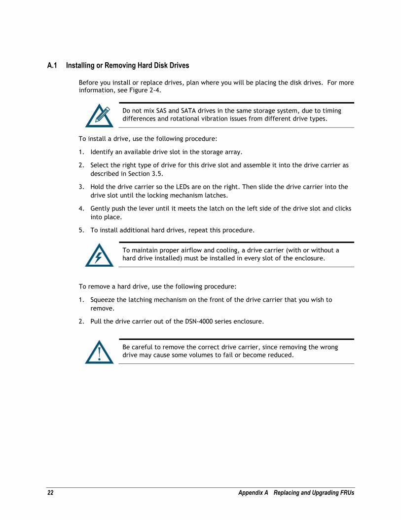
Before you install or replace drives, plan where you will be placing the disk drives. For more information, see Figure 2-4.
Do not mix SAS and SATA drives in the same storage system, due to timing
differences and rotational vibration issues from different drive types.
To install a drive, use the following procedure:
1. Identify an available drive slot in the storage array.
2. Select the right type of drive for this drive slot and assemble it into the drive carrier as
described in Section 3.5.
3. Hold the drive carrier so the LEDs are on the right. Then slide the drive carrier into the
drive slot until the locking mechanism latches.
4. Gently push the lever until it meets the latch on the left side of the drive slot and clicks
into place.
5. To install additional hard drives, repeat this procedure.
To maintain proper airflow and cooling, a drive carrier (with or without a
hard drive installed) must be installed in every slot of the enclosure.
To remove a hard drive, use the following procedure:
1. Squeeze the latching mechanism on the front of the drive carrier that you wish to
remove.
2. Pull the drive carrier out of the DSN-4000 series enclosure.
Be careful to remove the correct drive carrier, since removing the wrong
drive may cause some volumes to fail or become reduced.

DSN-4000 Series Hardware Reference Guide 23
A.2 Replacing a Power Supply Module
The redundant power supplies on the DSN-4000 series are field-replaceable units. You can
replace a power supply module without removing the enclosure from the rack.
To remove the power supply module:
1. Verify that the power supply LED is amber or red.
2. Switch off the power to the power supply module you plan to replace.
3. Unplug the power cord.
4. Loosen and remove the retaining screw on the left side of the power supply module.
5. Pull the power supply module out of the DSN-4000 series enclosure.
Figure A-1. Removing a Power Supply Module
To install the replacement power supply:
1. Carefully slide the power supply module into the DSN-4000 series enclosure.
2. Install and tighten the retaining screw on the left side of the power supply.
3. Plug in the power cord.
4. Switch on the power supply.
5. Verify that the new power supply LED is green.
Retaining Screw for Power Supply #0
Retaining Screw for Power Supply #1
Status LED for Power Supply #0
Status LED for Power Supply #1

24 Appendix A Replacing and Upgrading FRUs
A.3 Replacing a Cooling Fan Module
The cooling fan modules on the DSN-4000 series are hot-swappable and can be replaced
while the system is running, without shutting down the system or removing the enclosure
from the rack.
To remove a cooling fan module:
1. Verify that the Fan Status LED is red to identify which cooling fan module has failed.
2. Loosen the two thumbscrews for the cooling fan module, as shown in Figure A-2.
3. Remove the cooling fan module from the Controller module.
Figure A-2. Removing a Cooling Fan Module
To install a replacement cooling fan module:
1. Align the tabs on the side of the cooling fan module with the slots in the controller
module rear panel, to ensure that the fan is installed in the correct orientation.
2. Slide the cooling fan module into the opening in the Controller module until it is fully
seated.
3. Tighten both of the thumbscrews.
4. Verify that the Fan Status LED is green.
Thumbscrew
Thumbscrew
Thumbscrew
Thumbscrew
Cooling Fan Module with Fans 0 and 1
Cooling Fan Module with Fans 2 and 3
DSN-4000 Series Hardware Reference Guide 25
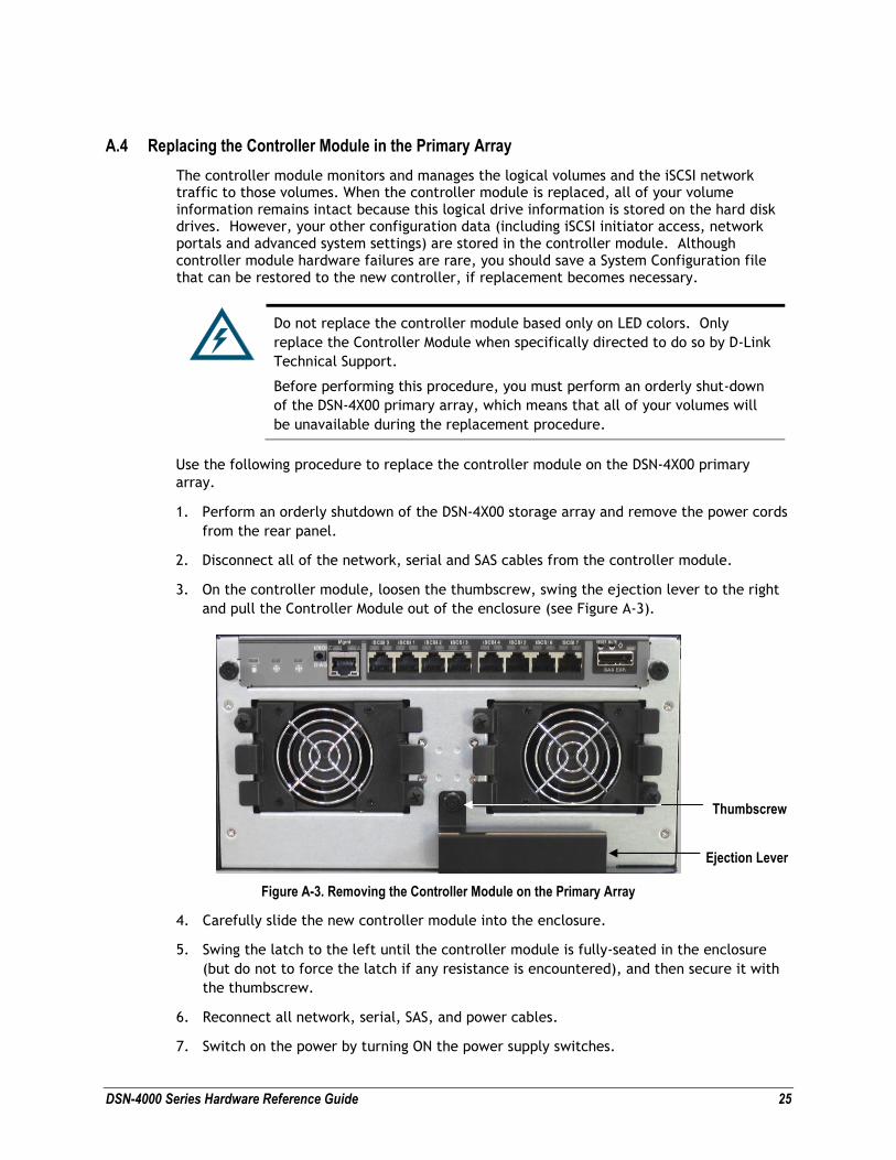
A.4 Replacing the Controller Module in the Primary Array
The controller module monitors and manages the logical volumes and the iSCSI network traffic to those volumes. When the controller module is replaced, all of your volume information remains intact because this logical drive information is stored on the hard disk drives. However, your other configuration data (including iSCSI initiator access, network portals and advanced system settings) are stored in the controller module. Although controller module hardware failures are rare, you should save a System Configuration file that can be restored to the new controller, if replacement becomes necessary.
Do not replace the controller module based only on LED colors. Only
replace the Controller Module when specifically directed to do so by D-Link
Technical Support.
Before performing this procedure, you must perform an orderly shut-down
of the DSN-4X00 primary array, which means that all of your volumes will
be unavailable during the replacement procedure.
Use the following procedure to replace the controller module on the DSN-4X00 primary
array.
1. Perform an orderly shutdown of the DSN-4X00 storage array and remove the power cords
from the rear panel.
2. Disconnect all of the network, serial and SAS cables from the controller module.
3. On the controller module, loosen the thumbscrew, swing the ejection lever to the right
and pull the Controller Module out of the enclosure (see Figure A-3).
Figure A-3. Removing the Controller Module on the Primary Array
4. Carefully slide the new controller module into the enclosure.
5. Swing the latch to the left until the controller module is fully-seated in the enclosure
(but do not to force the latch if any resistance is encountered), and then secure it with
the thumbscrew.
6. Reconnect all network, serial, SAS, and power cables.
7. Switch on the power by turning ON the power supply switches.
Thumbscrew
Ejection Lever
26 Appendix A Replacing and Upgrading FRUs
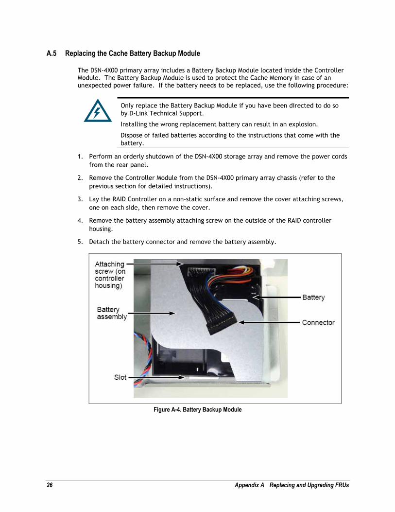
A.5 Replacing the Cache Battery Backup Module
The DSN-4X00 primary array includes a Battery Backup Module located inside the Controller Module. The Battery Backup Module is used to protect the Cache Memory in case of an unexpected power failure. If the battery needs to be replaced, use the following procedure:
Only replace the Battery Backup Module if you have been directed to do so
by D-Link Technical Support.
Installing the wrong replacement battery can result in an explosion.
Dispose of failed batteries according to the instructions that come with the
battery.
1. Perform an orderly shutdown of the DSN-4X00 storage array and remove the power cords
from the rear panel.
2. Remove the Controller Module from the DSN-4X00 primary array chassis (refer to the
previous section for detailed instructions).
3. Lay the RAID Controller on a non-static surface and remove the cover attaching screws,
one on each side, then remove the cover.
4. Remove the battery assembly attaching screw on the outside of the RAID controller
housing.
5. Detach the battery connector and remove the battery assembly.
Figure A-4. Battery Backup Module
DSN-4000 Series Hardware Reference Guide 27
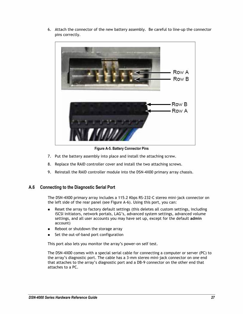
6. Attach the connector of the new battery assembly. Be careful to line-up the connector
pins correctly.
Figure A-5. Battery Connector Pins
7. Put the battery assembly into place and install the attaching screw.
8. Replace the RAID controller cover and install the two attaching screws.
9. Reinstall the RAID controller module into the DSN-4X00 primary array chassis.
A.6 Connecting to the Diagnostic Serial Port
The DSN-4X00 primary array includes a 115.2 Kbps RS-232-C stereo mini-jack connector on the left side of the rear panel (see Figure A-6). Using this port, you can:
� Reset the array to factory default settings (this deletes all custom settings, including iSCSI initiators, network portals, LAG’s, advanced system settings, advanced volume settings, and all user accounts you may have set up, except for the default admin account)
� Reboot or shutdown the storage array
� Set the out-of-band port configuration
This port also lets you monitor the array’s power-on self test.
The DSN-4X00 comes with a special serial cable for connecting a computer or server (PC) to
the array’s diagnostic port. The cable has a 3-mm stereo mini-jack connector on one end
that attaches to the array’s diagnostic port and a DB-9 connector on the other end that
attaches to a PC.

28 Appendix A Replacing and Upgrading FRUs
The PC must have a terminal-emulation program (such as HyperTerminal) installed. The program should be configured as follows:
� Baud rate: 115,200 bps
� Data bits: 8
� Parity: None
� Stop bits: 1
� Hardware handshake: None
Figure A-6. Diagnostic Serial Port on Array Rear Panel
To reset or reboot the array or set the out-of-band port configuration:
1. Connect the diagnostic port to the serial port of a PC.
2. Start your terminal-emulation program and configure it as indicated above.
3. When prompted, login with your username and password. The following menu appears.
Figure A-7. Administrative Menu from the Serial Diagnostic Port
4. Enter the number that corresponds to the action you want to perform.
5. Follow the screen prompts to complete the activity.
If you shutdown the system using Option 2, you will need to disconnect and
re-connect the AC power cords before you can power the system on again.
RS-232 Serial Diagnostic Port

DSN-4000 Series Hardware Reference Guide 29
Appendix B Installing the System in a Rack
This appendix describes how to install the DSN-4000 series array in a rack.
At least two persons are required to safely lift, place, and attach the DSN-
4000 series array system into a rack.
Do not lift or move the DSN-4000 series storage system by the handles,
power supply or the Controller Module. Instead, hold the complete system
itself.
Be sure all switches are OFF before installing the DSN-4000 series storage
system or replacing any components.
To install the DSN-4000 series storage system into a rack:
1. Select the locations in the rack where you will be installing the rails that will support
the primary array and any expansion arrays (if appropriate). When selecting a location,
note the location of the three mounting holes on the rack’s front vertical supports and
the two mounting holes on the back vertical supports, as shown in the following figure.
These locations will become important when you secure the rails and the array to the
rack.
Figure B-1. Example of Mounting Hole Locations on the Front Rails
2. Check the fit of the mounting rails in your rack system.
3. Adjust the length of the mounting rails as needed.
4. Attach the mounting rail assemblies to the outside of the rack posts, using the attaching
screws from your rack system. Be sure the support is on the bottom facing inward.
5. Square the rail assemblies in the rack.
6. Tighten the adjustment screws and the attaching screws.
7. Place the DSN-4000 series storage system onto the rails.
8. Secure the DSN-4X00 storage system to the rack through each handle, using the
attaching screws from your rack system.

30 Appendix B Installing the System in a Rack
Figure B-2. Securing the Rails to the Rack