CYCLIC TESTING AND COMPARISON OF LOCALLY CFRP …
11
1 CYCLIC TESTING AND COMPARISON OF LOCALLY CFRP CONFINED HSS BRACES AND BUCKLING-RESTRAINED BRACES Cem HAYDAROGLU 1 Cigdem AVCI-KARATAS 2 and Oguz C. CELIK 3 ABSTRACT This study describes a comparative experimental study into partially retrofitted steel tubular braces using advanced composites, and a steel-core buckling restrained brace (BRB). Retrofitting the locally critical sections of a tubular brace (both at net and mid-span sections) with CFRP members are proposed for both delaying local buckling and potential net section failures to have a better seismic performance and longer fracture life. Two tubular brace specimens (bare, TB-1, and partially retrofitted, TB-2) and a newly developed BRB (namely BRB-SC) having a rectangular steel core and surrounded with high strength grout (>60MPa) were designed per AISC specifications and subjected to quasi-static reversed cyclic testing protocols to compare their inelastic performances. Partial CFRP wrapping of tubular braces delayed possible local failures and increased the overall ductility up to a ductility level of 7. The tested BRB performed balanced, repeatable, stable, and almost symmetric hysteretic behavior both in tension and compression. A ductility level of 10 has been achieved in BRB-SC. Dissipated energies per steel volume used for TB-1, TB-2, and BRB-SC have been obtained as 0.0150, 0.0209, and 0.0356 kNmm/mm 3 , respectively. INTRODUCTION While both classical (i.e. buckling) and buckling restrained braces (BRBs) have merits in seismic design applications, no comparative quantitative data exist to help the engineer determine which of the two systems is preferable for project specific requirements. In an attempt to provide some quantitative data for this purpose, this paper describes and compares the results from cyclic testing of three different specimens. Braces of steel frames are subjected to large axial (tension or compression) reversed cyclic displacements under large earthquake excitations (Celik et al., 2005). Although classical hollow section steel (HSS) braces stretch under tension and buckle under compression, BRBs display a balanced hysteretic behavior under reversed cyclic tension and compression forces and dissipate significant amount of seismic energy (Avci-Karatas et al., 2013; Celik and Bruneau, 2009). The most vulnerable parts of HSS braces are the net (i.e. brace-to-gusset connections) and mid-span sections due to early fractures and cyclic local buckling, respectively (Haydaroglu and Celik, 2012; Haydaroglu et al., 2011a). Braces with lower fracture life may lead to a reduced energy dissipation capacity and soft/weak stories resulting from excessive lateral drifts. 1 Ph.D. Candidate, Senior Structural Engineer, Arup Turkey, Istanbul, [email protected] 2 Assistant Professor, Yalova University, Transportation Engineering Department, Yalova, [email protected] 3 Professor, Coordinator, Structural & Earthquake Engineering Working Group, Faculty of Architecture, Istanbul Technical University, Istanbul, [email protected]
Transcript of CYCLIC TESTING AND COMPARISON OF LOCALLY CFRP …

1
CYCLIC TESTING AND COMPARISON OF LOCALLY CFRP CONFINED HSS BRACES AND
BUCKLING-RESTRAINED BRACES
Cem HAYDAROGLU1 Cigdem AVCI-KARATAS2 and Oguz C. CELIK3
ABSTRACT
This study describes a comparative experimental study into partially retrofitted steel tubular braces using advanced composites, and a steel-core buckling restrained brace (BRB). Retrofitting the locally critical sections of a tubular brace (both at net and mid-span sections) with CFRP members are proposed for both delaying local buckling and potential net section failures to have a better seismic performance and longer fracture life. Two tubular brace specimens (bare, TB-1, and partially retrofitted, TB-2) and a newly developed BRB (namely BRB-SC) having a rectangular steel core and surrounded with high strength grout (>60MPa) were designed per AISC specifications and subjected to quasi-static reversed cyclic testing protocols to compare their inelastic performances.
Partial CFRP wrapping of tubular braces delayed possible local failures and increased the overall ductility up to a ductility level of 7. The tested BRB performed balanced, repeatable, stable, and almost symmetric hysteretic behavior both in tension and compression. A ductility level of 10 has been achieved in BRB-SC. Dissipated energies per steel volume used for TB-1, TB-2, and BRB-SC have been obtained as 0.0150, 0.0209, and 0.0356 kNmm/mm3, respectively.
INTRODUCTION
While both classical (i.e. buckling) and buckling restrained braces (BRBs) have merits in seismic design applications, no comparative quantitative data exist to help the engineer determine which of the two systems is preferable for project specific requirements. In an attempt to provide some quantitative data for this purpose, this paper describes and compares the results from cyclic testing of three different specimens. Braces of steel frames are subjected to large axial (tension or compression) reversed cyclic displacements under large earthquake excitations (Celik et al., 2005). Although classical hollow section steel (HSS) braces stretch under tension and buckle under compression, BRBs display a balanced hysteretic behavior under reversed cyclic tension and compression forces and dissipate significant amount of seismic energy (Avci-Karatas et al., 2013; Celik and Bruneau, 2009). The most vulnerable parts of HSS braces are the net (i.e. brace-to-gusset connections) and mid-span sections due to early fractures and cyclic local buckling, respectively (Haydaroglu and Celik, 2012; Haydaroglu et al., 2011a). Braces with lower fracture life may lead to a reduced energy dissipation capacity and soft/weak stories resulting from excessive lateral drifts. 1 Ph.D. Candidate, Senior Structural Engineer, Arup Turkey, Istanbul, [email protected] 2 Assistant Professor, Yalova University, Transportation Engineering Department, Yalova, [email protected] 3 Professor, Coordinator, Structural & Earthquake Engineering Working Group, Faculty of Architecture, Istanbul Technical University, Istanbul, [email protected]

2
To improve hysteretic behavior of HSS braces by both delaying local buckling and net section failures, critical sections of the braces could be locally retrofitted/confined with CFRP members (Haydaroglu et al., 2011b). For this purpose, CFRP plates serving as sectional reinforcement could be epoxy-bonded around the net sections and then wrapped with CFRP sheets to prevent debonding. As for the mid-span section, a part of the mid-span region could be partially wrapped (along a distance of expected high compressive strains) with CFRP sheets to delay local buckling, obtain longer fracture life, and higher cumulative energy dissipation. On the other hand, BRBs have a fully restrained steel core and behave independent from the brace length (Avci_Karatas and Celik, 2013; Avci_Karatas, 2012; Celik and Bruneau, 2009). To investigate hysteretic behavior of locally restrained HSS braces and steel core BRBs, two large scale square HSS specimens (TB-1 and TB-2) and one BRB (BRB-SC) having a steel core and outer tube designed per AISC Specifications (LRFD and Seismic Provisions), were manufactured and cyclically tested under quasi-static displacement histories in the Structural and Earthquake Engineering Laboratory (STEEL) of Istanbul Technical University. ATC-24 (1992) and AISC 341 (2010) loading protocols were adopted for tubular braces and BRB, respectively.
This paper reports on the cyclic inelastic behavior of CFRP retrofitted tubular steel braces and a BRB having steel core and outer tube. The obtained strength, stiffness, maximum displacement ductilities, cumulative dissipated energies, and a new concept amount of dissipated energy per steel volume are compared.
TEST SET-UP
A versatile test set-up composed of a steel L frame was designed and constructed for testing brace specimens having different size and lengths (Haydaroglu et al., 2010). Test set-up was designed to remain elastic under maximum actuator force. The steel grade used for testing set-up was S275JR. All members and connections were designed with a safety factor of at least 2.0. Loads were applied by a computer-controlled MTS hydraulic actuator, capable of producing up to 250kN horizontal loading. Displacement capacity of the actuator is ±300mm. Displacement-controlled testing was carried out via LVDTs mounted on the column face at the same height with the actuator. The specimens were tested a 38-degree diagonal bracing configuration with the steel foundation beam (Fig.1).
Figure 1. Testing set-ups; (a) for tubular braces (TB-1 and TB-2), (b) for BRB-SC
(a)
(b)

C.Haydaroglu, C.Karatas-Avci and O.C.Celik 3
Steel out-of-plane supports/frames were designed and constructed in order to prevent possible out of plane displacements of the test set-up (Fig. 2). Rollers were provided at two levels to support the column of the test set-up.
Figure 2. Out-of-plane support system; (a) Diagonal framing, (b) Rollers
SPECIMENS
All specimens were designed in accordance with the AISC-LRFD (2010b) and AISC-341 Seismic Provisions (2010a) as appropriate. Two specimens (namely TB-1 and TB-2) made of S235JR grade steel were designed and constructed using tubular braces having square cross-sections. Locally available tube braces of 60mm by 60mm and t=3mm wall thickness were selected.
Slotted end connection detail with 20mm slot length was adopted in brace-to-gusset connections. The first specimen was designed as a bare, reference specimen having a regular slotted end welded connection. The second was a similar specimen (i.e. with the same KL/r and b/t ratios) having 1200mm (20xsectional width (b) or 34% of clear brace length) CFRP sheet wrap at its mid-span section and CFRP plate+sheet reinforcement at brace-to-gusset connections (Fig. 3). Tubular specimens had KL/r (global slenderness) and b/t (local slenderness) ratios of 77 and 17, respectively.
(a)
(b)
Figure 3. Partially CFRP retrofit of Specimen TB-2; (a) Net section retrofit, (b) Mid-span retrofit
Gas metal arc welding and grade SG2 filler rod were used for fillet welds used in brace-to- gusset connections. Ultimate tensile strength of SG2 is 550 N/mm2. In TB-2, CFRP members were bonded to the brace surface using MBrace epoxy components.
(a) (b)
CFRP Plate (620mm)
CFRP Sheet Wrap (340mm) CFRP Sheet Wrap
(1200mm)

4
CFRP MBrace Laminate LM10/1.4 has a modulus of elasticity (E) of 165000N/mm2, tensile strength of 2500N/mm2, and a maximum elongation of 1.5%. CFRP MBrace Fiber C1-23 has an E modulus of 240000N/mm2, tensile strength of 3800N/mm2, and a maximum elongation of 1.55%. Surfaces of Specimen TB-2 were cleaned and prepared by a spiral prior to the CFRP application (Fig. 4a). A safety factor of 2.0 was used for the design of epoxy bonding (Fig. 4b) and CFRP member areas.
Figure 4. CFRP application steps; (a) Surface preparation by using spiral machine, (b) CFRP bonding
The third specimen (BRB-SC) used single bolted (pinned) end connections and rectangular shaped core plate (16mmx30mm) made of S235JR steel grade. Yielding core length is selected as 67% of the total length, Lysc ≤ 1410mm. In order to prevent local and global buckling under compression cycles, steel-core of the brace was surrounded by a high strength mortar (64MPa) filled steel square HSS that provides continuous lateral support. The BRB specimen with steel-core and steel outer tube and simple end details was designed and fabricated. General views from the end connection and longitudinal section are given in Fig. 5. The geometrical parameters are summarized in Table 1. The length and width of the yielding portion of the brace are denoted by Lysc and bysc, respectively. Likewise, Lcon and bcon are the length and width of the connection portion. The transition zone has a length of Ltr and a width of btr. The thickness of the core is given by t. Total length of the BRB is limited to 2275mm in this research. Cross-section properties of the steel outer tubes were 140mmx140mmx5mm. Higher Pe (Euler buckling load)/Pysc (Yield load of core) ratio of 30.9 (> 1.5) was used in this work for BRB-SC. The steel-core is coated with a three-layer interface made of polytetrafluoroethylene as the unbonding material.
Table 1. Geometrical parameters of the BRB-SC’s steel core
Specimen Lysc (mm)
bysc (mm)
t (mm)
Lcon (mm)
bcon (mm)
Ltr (mm)
btr (mm)
BRB-SC 1410 30 16 185 165 249 100
Figure 5. (a,b) General views from BRB-SC end connections, (c) Longitudinal section
(a) (b)
(c) (a) (b)

C.Haydaroglu, C.Karatas-Avci and O.C.Celik 5
According to AISC 341-10 [12], axial yield strength of the BRB, Pysc, shall be determined by Eq. 1: Pysc = RyFyscAsc (1) where and are the compression and strain-hardening adjustment factors, respectively. Ry is the ratio of the expected yield stress to the specified minimum yield stress. Fysc and Asc are the specified actual yield stress of the core as determined from the coupon tests and the net area of the core, respectively. The factor is calculated as the ratio of the maximum tension force (Tmax) measured from the qualification tests to the yield force, Pysc, of the test specimen. The factor is calculated as the ratio of maximum compression force (Pmax) to the maximum tension force. For preliminary analysis of the brace, and were assumed as 1.15 and 1.45, respectively in this work.
Instrumentation for the experiments has been designed to measure global response of the steel test set-up and local performance of the specimens. Displacement-controlled testing was carried out via LVDTs mounted on the column face at the same height with the MTS actuator. Strain-gauges (at 1/4, 2/4, 3/4 points of the specimens) and several LVDTs were installed at critical points of the set-up. The LVDT and strain-gauge layouts were identical for both specimens. Labels and locations for LVDTs are given in Fig. 6.
Figure 6. Instrumentation; (a) for TB-1 and TB-2, (b) for BRB-SC
(a)
(b)

6
MATERIAL TESTS
ASTM A370-08a standard coupon tests were carried out in order to determine the mechanical properties of steel materials from which the TB-1 and TB-2 square tubular braces and BRB-SC’s steel core were produced. Prior to testing, these material data were used in static pushover analyses of the specimens using SAP2000 v14 to predict the load-displacement curves of the specimens. Stress-strain relations from tensile coupon test specimens are shown in Fig. 7a and Fig. 7b. A typical necking down image before rupture is given in Fig. 7c. Compression tests of the infill/grout material revealed that the specified 7-day and 28-day strengths were 52.3MPa and 64.1MPa, respectively.
0.0 0.1 0.2 0.3 0.40
50100150200250300350400450
Str
ess
(MP
a)
Strain (mm/mm)
(a)
0.0 0.1 0.2 0.3 0.40
50100150200250300350400450
Str
ess
(MP
a)
Strain (mm/mm)
(b)
(c)
Figure 7. (a) Average stress-strain curves for TB-1 and TB-2, (b) Stress-strain curve for BRB-SC, (c) Close-up view of necking for coupons
LOADING PROTOCOL
Quasi-static cyclic testing was carried out for each specimen in accordance with ATC-24 (1992) and AISC 341 (2010a) for tubular braces (TB-1 and TB-2, Fig.8a) and BRB-SC (Fig. 8b), respectively. Top horizontal displacement is related to the brace axial displacement and was taken as the displacement control parameter. To facilitate comparison between the experimental results for tubular specimens, the same cyclic displacement history that was applied to TB-1 was also applied to TB-2. Loading protocol used for tubular specimens and the vertical dotted lines showing failure displacement of these braces are depicted in Fig. 8a. Although additional cycles to satisfy the Office of Statewide Health Planning and Development (OSHPD) requirement for cumulative inelastic displacement were proposed (Fig. 8b), the BRB did not arrive at those cycles.
0 5 10 15 20 25-40
-30
-20
-10
0
10
20
30
40TB-1
TB-2
7y6y4y
5y
3y2y
To
p D
isp
lace
men
t (m
m)
Number of Cycles
1y
(a)
(b)
Figure 8. Loading protocols; (a) for TB-1 and TB-2, (b) for BRB-SC

C.Haydaroglu, C.Karatas-Avci and O.C.Celik 7
EXPERIMENTAL OBSERVATIONS
For each specimen, experimental base shear versus lateral drift hysteresis and views from the tests are shown in Fig. 9. Specimen TB-1 (the bare specimen) exhibited completely linear behavior until the yield (buckling) level. Note that, after buckling, the differences between tension and compression strengths were visible in the hystereses. The reached maximum tension and compression capacities are 160kN and 73kN, respectively. Since the brace used a slotted end connection, upon repeated loading, inelastic strains accumulated in those regions as expected. In particular, significant elongation was observed at the lower slotted net section in tension. Occurrence of local buckling was recognized in this lengthened slotted end region, due to compression during the subsequent loading cycle. Finally, at displacement ductility of µ=6, which is defined as the fracture displacement divided by the yield/buckling displacement, TB-1 fractured at lower brace-to-gusset net section (Fig. 11a). During whole testing, no local buckling developed at the mid-span section.
-2 -1 0 1 2-200
-150
-100
-50
0
50
100
150
200
Bas
e S
hea
r (k
N)
Drift (%)
-2 -1 0 1 2-200
-150
-100
-50
0
50
100
150
200
Bas
e S
hea
r (k
N)
Drift (%)
-4 -3 -2 -1 0 1 2 3 4-300-250-200-150-100
-500
50100150200250300
Bas
e S
hea
r (k
N)
Drift (%)
Figure 9. Base shear vs. drift hysteresis curves for specimens (a) Hysteresis of TB-1; (b) Buckled shape of TB-1 (c) Hysteresis of TB-2; (d) Buckled shape of TB-2; (e) Hysteresis of BRB-SC; (h) A view from the test
(a) (b)
(c)
(e)
(d)
(f)

8
As shown in Fig. 9b, Specimen TB-2 (having a 1200mm long CFRP sheet wrap at its mid-span region and CFRP plate+sheet reinforcement at brace-to-gusset connections) showed excellent hysteretic behavior until 7δy. Fuller hysteretic curves were obtained when compared to TB-1. The reached maximum tension and compression capacities are 168kN and 88kN, respectively. No significant change was observed in tension strength, while an increase up to 20% in compression strength was recorded. The specimen experienced local buckling at -5δy displacement level at the middle section under the CFRP wrap. Note that, CFRP wrap helped to delay occurrence of local buckling effectively, leading to a higher displacement ductility. TB-2 fractured around the middle section at 7δy (Fig. 11b). Strain gauge data, gathered from the mid-point of the tubular braces and steel core of BRB-SC, showing base shear versus axial strain hysteretic curves are given in Fig. 10.
-10 -5 0 5 10 15 20-150
-100
-50
0
50
100
150
200
Bas
e S
hea
r (k
N)
Strain(mm/mm) (10-3)
TB-1
-10 -5 0 5 10 15 20-150
-100
-50
0
50
100
150
200
Bas
e S
hear
(kN
)
Strain(mm/mm) (10-3)
TB-2
-10 -5 0 5 10 15 20-150
-100
-50
0
50
100
150
200
Bas
e S
hea
r (k
N)
Strain(mm/mm) (10-3)
BRB-SC
Figure 10. Base shear vs. strain hysteresis curves for specimens; (a) Hysteresis of TB-1; (b) Hysteresis of TB-2; (c) Hysteresis of BRB-SC
The experimental value of by, the yield displacement, was obtained as 5.90mm for BRB-SC. Percent drift is computed as the difference between the horizontal distance between the actuator lateral and top of steel foundation beam (1860mm). Experimental results show that a maximum drift of 3.17% that corresponds to ±59.00mm lateral displacement was obtained for BRB-SC. Maximum displacement ductility of brace () was calculated as the ratio of maximum inelastic displacement, u, to the yield displacement, by, and obtained as 10. Fracture of rectangular steel core is given Fig.11c and Fig. 11d. Note that no fractures in the welds or any signs of local or global instability were observed during the test. For inelastic cycles at 10by, the ratio of maximum compression force to the maximum tension force (i.e. ) exceeded 1.3 in BRB-SC. At -10by, the maximum values were obtained as 1.65 (27% larger). The reached maximum tension and compression capacities are +149.63kN and -247.38kN, respectively. Measured out-of-plane displacements of mid-span of BRB-SC’s outer tube were measured between -1.64mm+1.24mm. These values prove that out-of-plane buckling was effectively prevented during testing. The force amplitude decreases after first cycles at
(a) (b)
(c)

C.Haydaroglu, C.Karatas-Avci and O.C.Celik 9
each displacement step but tends to stabilize quite fast. This is possibly due to a progressive detachment between the core and mortar. Estimation of experimental success ratio in terms of yield strength and initial stiffness were over 90%.
Figure 11. Damage levels of specimens; (a) TB-1, (b) TB-2, (c) High-mode buckling response of BRB-SC, (d) Close up view of mid-section fracture of BRB-SC’s steel core
EVALUATION AND COMPARISONS
Experimental results show that BRB had fuller and almost similar hysteresis under tension and compression as expected. In TB-2, local CFRP confinement of HSS braces increased ductility and energy dissipation when compared to the values obtained for TB-1. For a better comparison between
0 1 2 3 4 5 6 7 8 9 10 110
10000
20000
30000
Fracture
En
ergy
Dis
s. p
er C
ycle
(k
N.m
m)
Ductility
2 TB-1 2 TB-2 BRB-SC
Fracture
0 5 10 15 20 25 30 350
50000
100000
150000
200000
250000
248508kN.mm
56935kN.mm
2 TB-1 2 TB-2 BRB-SC
Cu
mu
lati
ve D
iss.
En
ergy
(k
N.m
m)
Number of Cycles
40755kN.mm
Figure 12. Hysteretic energy dissipation curves; (a) Energy dissipation per cycle versus ductility, (b) Cumulative dissipated energy curves
HSS braces and the BRB, considering that the buckling braces should be complemented by simultaneously acting tension braces, the behavioral values are doubled for TB-1 and TB-2 (i.e. 2TB-1 and 2TB-2). Cumulative energy dissipation and dissipated energy per cycle versus specimen ductility are depicted in Fig. 12. Although similar energies were dissipated in lower ductility (e.g. up to a ductility of 4) values (or total number of cycles smaller than 20), a significant difference was observed at larger ductilities (say >5). Fracture from local buckling occurred in the HSS braces. CFRP
(a) (b)
(c) (d)
(a) (b)
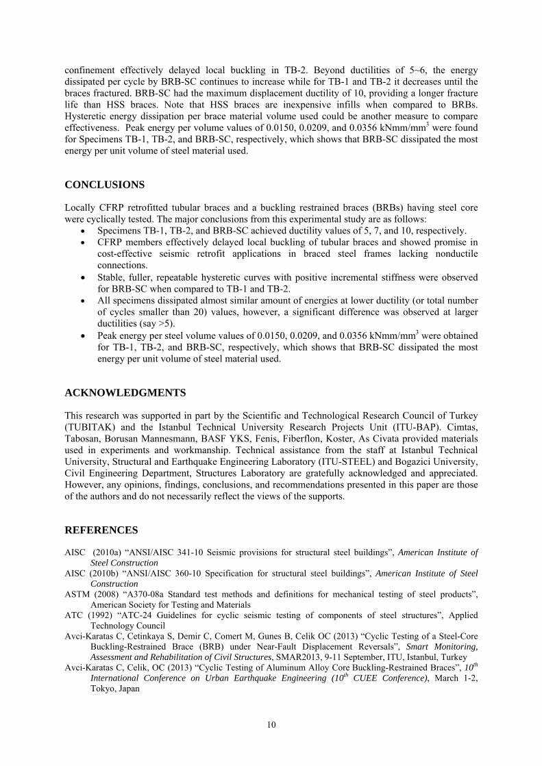
10
confinement effectively delayed local buckling in TB-2. Beyond ductilities of 5~6, the energy dissipated per cycle by BRB-SC continues to increase while for TB-1 and TB-2 it decreases until the braces fractured. BRB-SC had the maximum displacement ductility of 10, providing a longer fracture life than HSS braces. Note that HSS braces are inexpensive infills when compared to BRBs. Hysteretic energy dissipation per brace material volume used could be another measure to compare effectiveness. Peak energy per volume values of 0.0150, 0.0209, and 0.0356 kNmm/mm3 were found for Specimens TB-1, TB-2, and BRB-SC, respectively, which shows that BRB-SC dissipated the most energy per unit volume of steel material used.
CONCLUSIONS
Locally CFRP retrofitted tubular braces and a buckling restrained braces (BRBs) having steel core were cyclically tested. The major conclusions from this experimental study are as follows:
Specimens TB-1, TB-2, and BRB-SC achieved ductility values of 5, 7, and 10, respectively. CFRP members effectively delayed local buckling of tubular braces and showed promise in
cost-effective seismic retrofit applications in braced steel frames lacking nonductile connections.
Stable, fuller, repeatable hysteretic curves with positive incremental stiffness were observed for BRB-SC when compared to TB-1 and TB-2.
All specimens dissipated almost similar amount of energies at lower ductility (or total number of cycles smaller than 20) values, however, a significant difference was observed at larger ductilities (say >5).
Peak energy per steel volume values of 0.0150, 0.0209, and 0.0356 kNmm/mm3 were obtained for TB-1, TB-2, and BRB-SC, respectively, which shows that BRB-SC dissipated the most energy per unit volume of steel material used.
ACKNOWLEDGMENTS
This research was supported in part by the Scientific and Technological Research Council of Turkey (TUBITAK) and the Istanbul Technical University Research Projects Unit (ITU-BAP). Cimtas, Tabosan, Borusan Mannesmann, BASF YKS, Fenis, Fiberflon, Koster, As Civata provided materials used in experiments and workmanship. Technical assistance from the staff at Istanbul Technical University, Structural and Earthquake Engineering Laboratory (ITU-STEEL) and Bogazici University, Civil Engineering Department, Structures Laboratory are gratefully acknowledged and appreciated. However, any opinions, findings, conclusions, and recommendations presented in this paper are those of the authors and do not necessarily reflect the views of the supports.
REFERENCES
AISC (2010a) “ANSI/AISC 341-10 Seismic provisions for structural steel buildings”, American Institute of Steel Construction
AISC (2010b) “ANSI/AISC 360-10 Specification for structural steel buildings”, American Institute of Steel Construction
ASTM (2008) “A370-08a Standard test methods and definitions for mechanical testing of steel products”, American Society for Testing and Materials
ATC (1992) “ATC-24 Guidelines for cyclic seismic testing of components of steel structures”, Applied Technology Council
Avci-Karatas C, Cetinkaya S, Demir C, Comert M, Gunes B, Celik OC (2013) “Cyclic Testing of a Steel-Core Buckling-Restrained Brace (BRB) under Near-Fault Displacement Reversals”, Smart Monitoring, Assessment and Rehabilitation of Civil Structures, SMAR2013, 9-11 September, ITU, Istanbul, Turkey
Avci-Karatas C, Celik, OC (2013) “Cyclic Testing of Aluminum Alloy Core Buckling-Restrained Braces”, 10th International Conference on Urban Earthquake Engineering (10th CUEE Conference), March 1-2, Tokyo, Japan

C.Haydaroglu, C.Karatas-Avci and O.C.Celik 11
Avci-Karatas C (2012), Design, Fabrication, and Cyclic Behavior of Steel and Aluminum Alloy Core Buckling-Restrained Braces (BRBs), Ph.D. Thesis, Istanbul Technical University, Istanbul, Turkey
Celik OC, Berman JW, Bruneau M (2005) “Cyclic Testing of Braces Laterally Restrained by Steel Studs”, Journal of Structural Engineering, ASCE, 131(7): 1114-1124
Celik OC, Bruneau M (2011) “Skewed Slab-on-Girder Steel Bridge Superstructures with Bidirectional-Ductile End Diaphragms,” Journal of Bridge Engineering, ASCE, 16(2): 207-218
Celik OC, Bruneau M (2009) “Seismic Behavior of Bidirectional-Resistant Ductile End Diaphragms with Buckling-Restrained Braces in Straight Steel Bridges,” Engineering Structures, 31(2): 380-393
Haydaroglu C, Celik OC (2012) “Experimental Investigation of Partially CFRP Wrapped Steel HSS Braces for Seismic Performance Improvement”, Proceedings of 15th World Conference on Earthquake Engineering (15WCEE 2012), Lisbon, Portugal, 24-28 September, Paper No:1230
Haydaroglu C, Taskin K, Celik OC (2011a) “Ductility Enhancement of Round HSS Braces Using CFRP Sheet Wraps”, Proceedings of 6th European Conference on Steel and Composite Structures (Eurosteel 2011), Budapest, Hungary, 31 August – 2 September, Vol B, 1143-1148
Haydaroglu C, Turker A, Taskin K, Celik OC (2011b) “Improving Hysteretic Behavior of Tubular Steel Braces Using Advanced Composites”, Proceedings of the 6th International Conference on Thin Walled Structures (ICTWS 2011)-Recent Research Advances and Trends, Timisoara, Romania, 5-7 September, Vol 2, 691-698
Haydaroglu C, Turker A, Taskin K, Celik OC (2010) “Cyclic Testing of Tubular Steel Braces with CFRP Reinforced Net Sections”, Proceedings of the 4th International Conference on Steel & Composite Structures, Sydney, Australia, CD-ROM, Paper No: SS-We010