Cyclic Behavior of Exterior Reinforced Beam-Column Joint...
9
IOSR Journal of Mechanical and Civil Engineering (IOSR-JMCE) e-ISSN: 2278-1684,p-ISSN: 2320-334X, Volume 11, Issue 4 Ver. III (Jul- Aug. 2014), PP 09-17 www.iosrjournals.org www.iosrjournals.org 9 | Page Cyclic Behavior of Exterior Reinforced Beam-Column Joint with Cross-Inclined Column Bars Suhasini M Kulkarni 1 , Yogesh D Patil 2 1 (Civil Engineering Department,Parul Institute of Engineering & Technology,India) 2 (Applied Mechanics Department, Sardar Vallabhbhai Patel National Institute of Technology,India) Abstract : The poor design practice of beam column joints is compounded by the high demand imposed by the adjoining flexural members (beams and columns) in the event of mobilizing their inelastic capacities to dissipate seismic energy. Unsafe design and detailing within the joint region jeopardizes the entire structure, even if other structural members conform to the design requirements. Beam moment reversals can produce high shear forces and bond breakdown into the joint resulting in cracking of the joint. The most important factors affecting the shear capacity of exterior RC beam-column joints are: the concrete compressive strength, the joint aspect ratio of the joints and number of lateral ties inside the joint. Advanced Reinforcement Pattern (ARP crossed inclined bars) is a feasible solution for increasing the shear capacity of the cyclically loaded exterior beam-column joints. The presence of inclined bars introduces an additional mechanism for shear transfer. External beam- column joints with crossed inclined reinforcement (ARP) modeled in Ansys Workbench showed high strength, and no appreciable deterioration even after reaching the maximum capacity. The load resisting capacity is increased as compared to that of seismic joint (IS: 13920-1993). A parametric study with cross inclined bars at the joint will be studied with different parameters like grade of concrete, tie ratio, joint aspect ratio, energy dissipation, yield ratio etc. A number of models in ANSYS 13.0 workbench and mechanical APDL are developed for different cyclic loads and boundary conditions. The joint with M50 grade of concrete is discussed in this paper. Keywords: Exterior Beam-Column Joint, Joint aspect Ratio, Joint Shear Strength I. INTRODUCTION Past three decades extensive research[1] has been carried out on studying the behavior of joints under seismic conditions through experimental and analytical studies. Various international codes of practices have been undergoing periodic revisions to incorporate the research findings into practice. The paper is aimed at making designers aware of the theoretical background on the design of beam column joints highlighting important parameters affecting seismic behavior of joints .It is generally recognized that beam-column joints can be critical regions in reinforced concrete frames designed for inelastic response to severe seismic attack. As a consequence of seismic moments in columns of opposite signs immediately above and below the joint, and similar beam moments reversal across the beam-column junction is subjected to horizontal and vertical shear forces whose magnitude is typically many times higher than in the adjacent beams and columns. Hence if not designed for the additional shear force generated in the joint, it will result in failure of joint. The reversal in moment across the joint also necessitates the provision of beam reinforcement on both faces (Tension/Compression). In addition to high shear force generated, the high bond stresses required to sustain this force gradient across the joint may cause bond failure and corresponding degradation of moment capacity accompanied by excessive drift. The joint is defined as the portion of the column within the depth of the deepest beam that frames into the column. In a moment resisting frame, beam-column joints are generally classified with respect to geometrical configuration and identified as interior, exterior and corner joints. The basic requirement of design is that the joint must be stronger than the adjoining beam or column member. It is important to see that the joint size is adequate in the early design phase, otherwise the column or beam size will have to be suitably modified to satisfy the joint shear strength or anchorage requirements. The design of beam – column joint is predominantly focused on providing joint shear strength and adequate anchorage within the joint.A review of the behaviour and design of different types of beam-column joints in reinforced concrete moment resisting frames under seismic loading illustrates that design and detailing provisions for the joints in the current Indian seismic codes IS 13920:1993 and IS 1893:2002 are not adequate to ensure prevention of brittle failure due to large shear forces which develop in the joint during earthquake. Therefore, the current code needs to be upgraded to incorporate shear design provisions for beam-column joints. Keeping the above discussion in view, the present research work has been undertaken with the objectives enlisted below.
Transcript of Cyclic Behavior of Exterior Reinforced Beam-Column Joint...

IOSR Journal of Mechanical and Civil Engineering (IOSR-JMCE)
e-ISSN: 2278-1684,p-ISSN: 2320-334X, Volume 11, Issue 4 Ver. III (Jul- Aug. 2014), PP 09-17 www.iosrjournals.org
www.iosrjournals.org 9 | Page
Cyclic Behavior of Exterior Reinforced Beam-Column Joint with
Cross-Inclined Column Bars
Suhasini M Kulkarni1 , Yogesh D Patil
2
1(Civil Engineering Department,Parul Institute of Engineering & Technology,India) 2(Applied Mechanics Department, Sardar Vallabhbhai Patel National Institute of Technology,India)
Abstract : The poor design practice of beam column joints is compounded by the high demand imposed by the
adjoining flexural members (beams and columns) in the event of mobilizing their inelastic capacities to dissipate
seismic energy. Unsafe design and detailing within the joint region jeopardizes the entire structure, even if other
structural members conform to the design requirements. Beam moment reversals can produce high shear forces
and bond breakdown into the joint resulting in cracking of the joint. The most important factors affecting the
shear capacity of exterior RC beam-column joints are: the concrete compressive strength, the joint aspect ratio
of the joints and number of lateral ties inside the joint. Advanced Reinforcement Pattern (ARP crossed inclined
bars) is a feasible solution for increasing the shear capacity of the cyclically loaded exterior beam-column
joints. The presence of inclined bars introduces an additional mechanism for shear transfer. External beam-
column joints with crossed inclined reinforcement (ARP) modeled in Ansys Workbench showed high strength,
and no appreciable deterioration even after reaching the maximum capacity. The load resisting capacity is increased as compared to that of seismic joint (IS: 13920-1993). A parametric study with cross inclined bars at
the joint will be studied with different parameters like grade of concrete, tie ratio, joint aspect ratio, energy
dissipation, yield ratio etc. A number of models in ANSYS 13.0 workbench and mechanical APDL are developed
for different cyclic loads and boundary conditions. The joint with M50 grade of concrete is discussed in this
paper.
Keywords: Exterior Beam-Column Joint, Joint aspect Ratio, Joint Shear Strength
I. INTRODUCTION Past three decades extensive research[1] has been carried out on studying the behavior of joints under
seismic conditions through experimental and analytical studies. Various international codes of practices have
been undergoing periodic revisions to incorporate the research findings into practice. The paper is aimed at
making designers aware of the theoretical background on the design of beam column joints highlighting
important parameters affecting seismic behavior of joints .It is generally recognized that beam-column joints can
be critical regions in reinforced concrete frames designed for inelastic response to severe seismic attack.
As a consequence of seismic moments in columns of opposite signs immediately above and below the
joint, and similar beam moments reversal across the beam-column junction is subjected to horizontal and
vertical shear forces whose magnitude is typically many times higher than in the adjacent beams and columns.
Hence if not designed for the additional shear force generated in the joint, it will result in failure of joint.
The reversal in moment across the joint also necessitates the provision of beam reinforcement on both faces (Tension/Compression). In addition to high shear force generated, the high bond stresses required to
sustain this force gradient across the joint may cause bond failure and corresponding degradation of moment
capacity accompanied by excessive drift. The joint is defined as the portion of the column within the depth of
the deepest beam that frames into the column.
In a moment resisting frame, beam-column joints are generally classified with respect to geometrical
configuration and identified as interior, exterior and corner joints. The basic requirement of design is that the
joint must be stronger than the adjoining beam or column member. It is important to see that the joint size is
adequate in the early design phase, otherwise the column or beam size will have to be suitably modified to
satisfy the joint shear strength or anchorage requirements. The design of beam – column joint is predominantly
focused on providing joint shear strength and adequate anchorage within the joint.A review of the behaviour and
design of different types of beam-column joints in reinforced concrete moment resisting frames under seismic loading illustrates that design and detailing provisions for the joints in the current Indian seismic codes IS
13920:1993 and IS 1893:2002 are not adequate to ensure prevention of brittle failure due to large shear forces
which develop in the joint during earthquake. Therefore, the current code needs to be upgraded to incorporate
shear design provisions for beam-column joints.
Keeping the above discussion in view, the present research work has been undertaken with the
objectives enlisted below.
Cyclic Behavior of Exterior Reinforced Beam-Column Joint with Cross-Inclined Column Bars
www.iosrjournals.org 10 | Page
i. To understand the different International Codal Provisions for the design of beam-column joint. ( ACI-
352-R, NZ-3505-1995, IS-13920-1993 and EURO- 8 )
ii. To study the different loads and resulting forces acting on beam-column joint.
iii. To understand the behaviour of joint resisting mechanism: primarily concrete and truss mechanism and
engineering design approach for calculation of joint shear
iv. To formulate Mathematical model for the combined concrete and truss mechanism.
v. Develop New External Reinforced Concrete joint (Type-2 as per ACI-352-R) configurations (crossed inclined bars in joint area)
vi. To study the influence of various key parameters: Compressive Strength of Concrete, Joint aspect ratio,
No of Stirrups in joint Area (Stirrups Ratio), and different axial Loads, on the behaviour external
beam- column joint for resisting the shear mechanism subjected to cyclic loading.
vii. To investigate the improvement / behaviour of crossed inclined bars in the external beam column joint
subjected to monotonic [2] and cyclic loading.
viii. To develop regression models for predicting the shear strength of cyclically loaded exterior beam-
column joint by considering all the key parameters.
1.1Beam Column Joints The functional requirement of a joint, which is the zone of intersection of beams and columns, is to
enable the adjoining members to develop and sustain their ultimate capacity. The demand on this finite size
element is always severe especially under seismic loading. The joints should have adequate strength and
stiffness to resist the internal forces induced by the framing members.
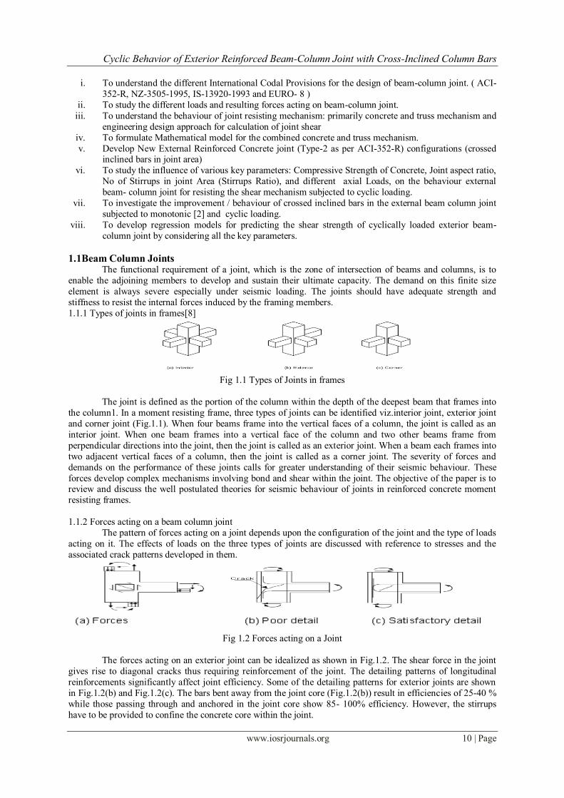
1.1.1 Types of joints in frames[8]
Fig 1.1 Types of Joints in frames
The joint is defined as the portion of the column within the depth of the deepest beam that frames into
the column1. In a moment resisting frame, three types of joints can be identified viz.interior joint, exterior joint
and corner joint (Fig.1.1). When four beams frame into the vertical faces of a column, the joint is called as an
interior joint. When one beam frames into a vertical face of the column and two other beams frame from
perpendicular directions into the joint, then the joint is called as an exterior joint. When a beam each frames into
two adjacent vertical faces of a column, then the joint is called as a corner joint. The severity of forces and
demands on the performance of these joints calls for greater understanding of their seismic behaviour. These
forces develop complex mechanisms involving bond and shear within the joint. The objective of the paper is to review and discuss the well postulated theories for seismic behaviour of joints in reinforced concrete moment
resisting frames.
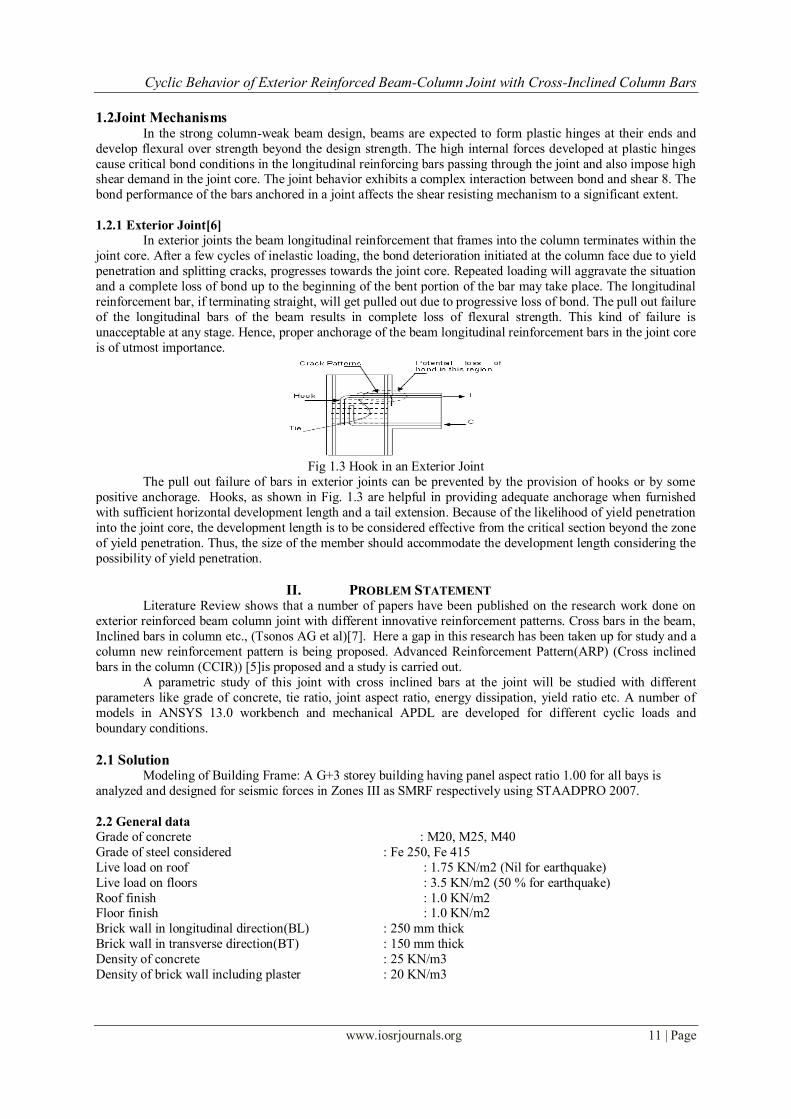
1.1.2 Forces acting on a beam column joint
The pattern of forces acting on a joint depends upon the configuration of the joint and the type of loads
acting on it. The effects of loads on the three types of joints are discussed with reference to stresses and the
associated crack patterns developed in them.
Fig 1.2 Forces acting on a Joint
The forces acting on an exterior joint can be idealized as shown in Fig.1.2. The shear force in the joint
gives rise to diagonal cracks thus requiring reinforcement of the joint. The detailing patterns of longitudinal
reinforcements significantly affect joint efficiency. Some of the detailing patterns for exterior joints are shown
in Fig.1.2(b) and Fig.1.2(c). The bars bent away from the joint core (Fig.1.2(b)) result in efficiencies of 25-40 %
while those passing through and anchored in the joint core show 85- 100% efficiency. However, the stirrups
have to be provided to confine the concrete core within the joint.
Cyclic Behavior of Exterior Reinforced Beam-Column Joint with Cross-Inclined Column Bars
www.iosrjournals.org 11 | Page
1.2Joint Mechanisms In the strong column-weak beam design, beams are expected to form plastic hinges at their ends and
develop flexural over strength beyond the design strength. The high internal forces developed at plastic hinges
cause critical bond conditions in the longitudinal reinforcing bars passing through the joint and also impose high shear demand in the joint core. The joint behavior exhibits a complex interaction between bond and shear 8. The
bond performance of the bars anchored in a joint affects the shear resisting mechanism to a significant extent.
1.2.1 Exterior Joint[6]
In exterior joints the beam longitudinal reinforcement that frames into the column terminates within the
joint core. After a few cycles of inelastic loading, the bond deterioration initiated at the column face due to yield
penetration and splitting cracks, progresses towards the joint core. Repeated loading will aggravate the situation
and a complete loss of bond up to the beginning of the bent portion of the bar may take place. The longitudinal
reinforcement bar, if terminating straight, will get pulled out due to progressive loss of bond. The pull out failure
of the longitudinal bars of the beam results in complete loss of flexural strength. This kind of failure is
unacceptable at any stage. Hence, proper anchorage of the beam longitudinal reinforcement bars in the joint core
is of utmost importance.
Fig 1.3 Hook in an Exterior Joint
The pull out failure of bars in exterior joints can be prevented by the provision of hooks or by some
positive anchorage. Hooks, as shown in Fig. 1.3 are helpful in providing adequate anchorage when furnished
with sufficient horizontal development length and a tail extension. Because of the likelihood of yield penetration
into the joint core, the development length is to be considered effective from the critical section beyond the zone
of yield penetration. Thus, the size of the member should accommodate the development length considering the
possibility of yield penetration.
II. PROBLEM STATEMENT Literature Review shows that a number of papers have been published on the research work done on
exterior reinforced beam column joint with different innovative reinforcement patterns. Cross bars in the beam,
Inclined bars in column etc., (Tsonos AG et al)[7]. Here a gap in this research has been taken up for study and a
column new reinforcement pattern is being proposed. Advanced Reinforcement Pattern(ARP) (Cross inclined
bars in the column (CCIR)) [5]is proposed and a study is carried out.
A parametric study of this joint with cross inclined bars at the joint will be studied with different
parameters like grade of concrete, tie ratio, joint aspect ratio, energy dissipation, yield ratio etc. A number of
models in ANSYS 13.0 workbench and mechanical APDL are developed for different cyclic loads and
boundary conditions.
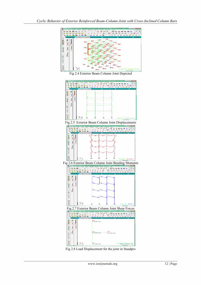
2.1 Solution Modeling of Building Frame: A G+3 storey building having panel aspect ratio 1.00 for all bays is
analyzed and designed for seismic forces in Zones III as SMRF respectively using STAADPRO 2007.
2.2 General data
Grade of concrete : M20, M25, M40
Grade of steel considered : Fe 250, Fe 415
Live load on roof : 1.75 KN/m2 (Nil for earthquake)
Live load on floors : 3.5 KN/m2 (50 % for earthquake)
Roof finish : 1.0 KN/m2 Floor finish : 1.0 KN/m2
Brick wall in longitudinal direction(BL) : 250 mm thick
Brick wall in transverse direction(BT) : 150 mm thick
Density of concrete : 25 KN/m3
Density of brick wall including plaster : 20 KN/m3
Cyclic Behavior of Exterior Reinforced Beam-Column Joint with Cross-Inclined Column Bars
www.iosrjournals.org 12 | Page
Fig 2.4 Exterior Beam Column Joint Depicted
Fig 2.5 Exterior Beam Column Joint Displacements
Fig 2.6 Exterior Beam Column Joint Bending Moments
Fig.2.7 Exterior Beam Column Joint Shear Forces
Fig 2.8 Load Displacement for the joint in Staadpro
Cyclic Behavior of Exterior Reinforced Beam-Column Joint with Cross-Inclined Column Bars
www.iosrjournals.org 13 | Page
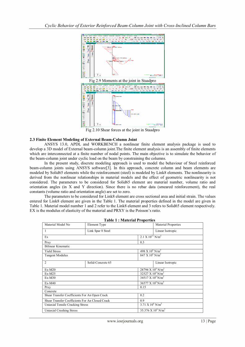
Fig 2.9 Moments at the joint in Staadpro
Fig 2.10 Shear forces at the joint in Staadpro
2.3 Finite Element Modeling of External Beam-Column Joint
ANSYS 13.0, APDL and WORKBENCH a nonlinear finite element analysis package is used to
develop a 3D model of External beam-column joint.The finite element analysis is an assembly of finite elements
which are interconnected at a finite number of nodal points. The main objective is to simulate the behavior of the beam-column joint under cyclic load on the beam by constraining the columns.
In the present study, discrete modeling approach is used to model the behaviour of Steel reinforced
beam-column joints using ANSYS software[3]. In this approach, concrete column and beam elements are
modeled by Solid65 elements while the reinforcement (steel) is modeled by Link8 elements. The nonlinearity is
derived from the nonlinear relationships in material models and the effect of geometric nonlinearity is not
considered. The parameters to be considered for Solid65 element are material number, volume ratio and
orientation angles (in X and Y direction). Since there is no rebar data (smeared reinforcement), the real
constants (volume ratio and orientation angle) are set to zero.
The parameters to be considered for Link8 element are cross sectional area and initial strain. The values
entered for Link8 element are given in the Table 1. The material properties defined in the model are given in
Table 1. Material model number 1 and 2 refer to the Link8 element and 3 refers to Solid65 element respectively. EX is the modulus of elasticity of the material and PRXY is the Poisson’s ratio.
Table 1 : Material Properties Material Model No Element Type Material Properties
1 Link Spar 8 Steel Linear Isotropic
Ex 2.1 X 10¹¹
N/m2
Prxy 0.3
Bilinear Kinematic
Yield Stress 498 X 106 N/m
2
Tangent Modulus 847 X 106 N/m
2
2 Solid-Concrete 65 Linear Isotropic
Ex-M20 28794 X 106 N/m
2
Ex-M25 32527 X 106 N/m
2
Ex-M30 34517 X 106 N/m
2
Ex-M40 36577 X 106 N/m
2
Prxy 0.15
Concrete
Shear Transfer Coefficients For An Open Crack 0.2
Shear Transfer Coefficients For An Closed Crack 0.9
Uniaxial Tensile Cracking Stress 3.71 X 10⁶ N/m2
Uniaxial Crushing Stress 35.376 X 10⁶ N/m
2

Cyclic Behavior of Exterior Reinforced Beam-Column Joint with Cross-Inclined Column Bars
www.iosrjournals.org 14 | Page
2.4 Column Cross Inclined Reinforcement
During strong earthquake, beam-column connections are subjected to severe reversed cyclic loading. If
they are not designed and detailed properly, their performance can significantly affect the overall response of a
ductile moment-resisting frame building. The performance of beam-column joints subjected to seismic forces
may be improved only if the major design considerations are satisfied. Though there is no explicit Indian Code
for design of beam-column joints for seismic forces, where as severe importance is given in many international
codes for design and detailing of joints.
Table 2 Reinforcement Details
Table 3: Geometry Details
2.5Results and Discussion
To understand the complex mechanism and safe behavior of joint, a non conventional way of
reinforcement such as the use of the crossed inclined bars (CCIR) are used in the joint area. In this study, to
improve the joint behavior and joint capacity following tasks are taken into consideration[4].
a) The influence of the Column Cross Inclined Bars on the shear strength of the cyclically loaded
exterior RC beam column joint.
b) The influence of the High Strength Concrete on the shear strength of the cyclically loaded
exterior RC beam column joint. c) To examine the effectiveness of exterior beam-column joints designed as per IS 1893: (part 1)
2002 and detailed as per IS 13920: 1993.
(a) (b) (c)
(d) (e) (f)
Fig 4.2. Ansys workbench models (a),(b),(c),(d),(e) depicting load cycle in reverse direction and (f) showing
the cyclic behavior in downward direction.
Specimen fck (MPa)
Reinforcement
Beam bars Stirrups
Column
bars Hoops Fy
Top Bottom
Seismic
(13920) 40
2 No
12 mm
2 No
12 mm
8mm
@125 c/c
4 No 12
mm
8mm @ 75
c/c 415
CCIR
40
2 No
12 mm
2 No
12 mm
8mm
@125 c/c
4 No 12
mm
8mm @ 75
c/c 415
Types of
Joints H (mm)
L
(mm) hc (mm)
bc
(mm)
hb
(mm)
bb
(mm)
CCIR 1800 1640 200 300 300 200
Cyclic Behavior of Exterior Reinforced Beam-Column Joint with Cross-Inclined Column Bars
www.iosrjournals.org 15 | Page
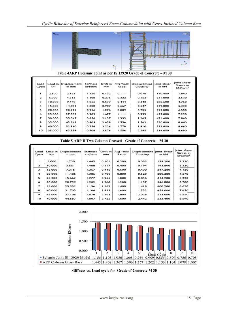
Table 4ARP I Seismic Joint as per IS 13920 Grade of Concrete – M 30
Table 5 ARP II Two Column Crossed - Grade of Concrete – M 30
Stiffness vs. Load cycle for Grade of Concrete M 30
1 2 3 4 5 6 7 8 9 10
Seismic Joint IS 13920 Model 1.156 1.108 1.056 1.008 0.956 0.909 0.856 0.809 0.756 0.708
ARP Column Cross Bars 1.445 1.408 1.367 1.306 1.277 1.202 1.156 1.104 1.078 1.007
0.000
0.500
1.000
1.500
2.000
Stiff
ness
KN
/mm
Load Cycle

Cyclic Behavior of Exterior Reinforced Beam-Column Joint with Cross-Inclined Column Bars
www.iosrjournals.org 16 | Page
Table 6 Stiffness and Displacement Ductility
Stiffness increases up to second cycle, and there after it decreases rapidly as the intensity of
cycle increases 21.3 % more in ARP 2 as compared to seismic joint ( IS13920)
At last cycle (displacement ductility 2.442 ) it is found that stiffness of ARP 2 it is 29.69 %
more than IS Seismic (13920).
Stiffness of specimen decrease as the intensity of cycle loading increases and after third cycle ( 13.1 % drift of ARP 2 ) rate of strength deteoriation is very fast.
Fig Joint Shear stress Vs. Load Cycle Joints as per IS 13920 and ARP II for Grade of Concrete M 30
Table 7 Joint shear stress
Joint shear stress developed in ARP 2 is less than SJ ( 13920) by 2%
III. Conclusions The most important factors affecting the shear capacity of exterior RC beam-column joints are: the
concrete compressive strength, No. of lateral ties in the joint,the joint aspect ratio of the joints, Column axial
load, Bar diameter of column longitudinal bars
ARP-2 (2-column crossed inclined bars), M30 gives a feasible solution for increasing the shear
capacity of the cyclically loaded beam-column joints.
1 2 3 4 5 6 7 8 9 10
Seismic Joint IS 13920 Model 1.84 3.53 4.76 5.33 6.55 7.23 7.86 8.68 8.88 8.91
ARP Column Cross Bars 2.32 3.23 4.12 4.67 5.22 5.78 6.67 7.65 8.55 8.89
0
1
2
3
4
5
6
7
8
9
10
Jo
int
Sh
ear
Str
ess N
/mm
2
Load Cycle

Cyclic Behavior of Exterior Reinforced Beam-Column Joint with Cross-Inclined Column Bars
www.iosrjournals.org 17 | Page
The presence of inclined bars introduces an additional mechanism of shear transfer. The greater the
joint aspect ratio (hb/hc) less will be the contribution of the crossed inclined bars to the joint shear
capacity.
External beam-column joints with crossed inclined reinforcement (ARP-2) showed high strength, and
no appreciable deterioration even after reaching the maximum capacity.
References [1]. S.M.Kulkarni, Y. D. Patil, ( 2012),“ A State-of-Art Review on Reinforced Concrete Beam-Column Joints", Journal of Information,
Knowledge and Research in Civil Engineering ISSN: 0975 – 6744 ,Nov 11 TO Oct 12 ,Volume 2, Issue 1, Page 94
[2]. S.M.Kulkarni, Y. D. Patil, ( 2012),“ Behavior of Exterior RC Beam-Column Joint Subjected to Monotonic Loading”, Indian
Journal of Technical Education, ISSN 0971-3034, pp.129-136.
[3]. S.M.Kulkarni, Y. D. Patil, (2012),”Analytical Study on Exterior RC Beam-Column Joint”,8th Biennial Conference on Structural
Engineering Convention (SEC-2012), ISBN 978-93-82062-72-1,pp634-640.
[4]. S.M.Kulkarni, Y. D. Patil, (2013), “A Novel Reinforcement Pattern for Exterior Reinforced Concrete Beam-Column Joint”,
Procedia Engineering (2013) pp. 184-193,vol 51C
[5]. S.M.Kulkarni, Y. D. Patil, (2014),”Evaluation of Advanced Reinforcement Pattern in Exterior RC Beam-Column Joint”,
International Journal of Scientific & Engineering Research, ISSN 2229-5518,Vol 5,Issue 3, pp 624-629.
[6]. Palay. T.: Park, R. and Priestey M.J.N.,(1978), “Reinforced Concrete Beam Column Joints under Seismic Actions.” ACI J.,
Proceedings V.75. No.11, pp. 585-593.
[7]. Tsonos AG, Tegos IA, Penelis GG. (1992), “Seismic resistance of type 2 exterior beam–column joints reinforced with inclined
bars”. ACI Struct J, Vol. 89 No.1, pp. 3–11.
[8]. ACI Committee 352R-02 (2002), "Recommendations for the design of beam-column joints in monolithic, reinforced concrete
structures", ACI Manual of Concrete Practice: Part 3, Detroit, American Concrete Institute.