CYBERSCAN TURBIDIMETER TB1000 - ENVCOCyberScan TB1000 2 3 Becoming Familiar with The Instrument...
16
INSTRUCTION MANUAL CYBERSCAN TURBIDIMETER TB1000 BENCH TURBIDITY METER Technology Made Easy …
Transcript of CYBERSCAN TURBIDIMETER TB1000 - ENVCOCyberScan TB1000 2 3 Becoming Familiar with The Instrument...
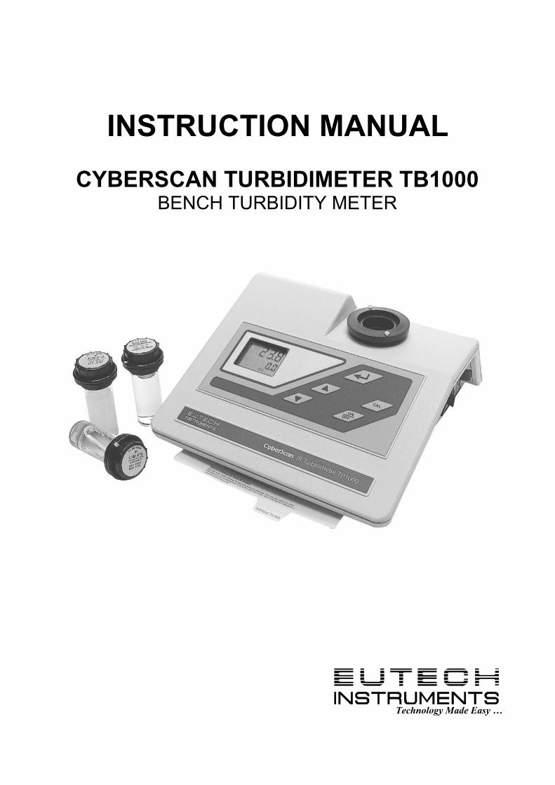
INSTRUCTION MANUAL
CYBERSCAN TURBIDIMETER TB1000 BENCH TURBIDITY METER
Technology Made Easy …


TABLE OF CONTENTS
1 INTRODUCTION 1
2 UNPACKING THE INSTRUMENT 1 2.1 Packing List of Contents 1
2.2 Unpacking and Inspection of the Instrument and Accessories 1
3 BECOMING FAMILIAR WITH THE INSTRUMENT 2
4 ROUTINE OPERATION 3 4.1 Grab Sample Measurement (Routine Measurement) 3
4.2 Pour Through Sample Measurement (Optional Accessory) 4
5 CALIBRATION PROCEDURES 4 5.1 Indexing the Calibration Standard(s) 4
5.2 Calibration Procedure 5
6 USER SELECTABLE PARAMETERS 6 6.1 Setting the Year 6
6.2 Setting the Day and Month 6
6.3 Setting the Time 6
6.4 Setting the Calibration Interval 6
6.5 Setting the Printing Function 7
6.6 Completing Selectable Parameters 7
7 TROUBLESHOOTING 7 7.1 System Warning Message(s) 7
7.1.1 Flashing “Cal” block 7 7.1.2 Flashing “LoBat” block 7
7.2 System Error Message(s) 7
7.3 Factory Default Parameters 8
8 ROUTINE MAINTENANCE 8 8.1 Cuvette Cleaning and Care 8
8.2 Lamp Replacement 8
8.3 Battery Replacement 9
9 SPECIFICATIONS 10
10 ACCESSORIES AND REPLACEMENT PARTS LIST 11 10.1 Glossary 11

CyberScan TB1000
1
1 Introduction Thank you for purchasing Eutech Instruments’ CyberScan Turbidimeter TB1000 series White Light or Infrared turbidity meter (CyberScan TB1000 hereafter). These turbidity meters have been designed for simple and easy measurement of turbidity. This manual contains simple steps to follow to ensure that your instrument is operating properly. This material assumes that the user knows how to obtain representative samples of their process and has some familiarity with measuring the turbidity of samples. The following sections describe how to use and care for your CyberScan TB1000. In certain instances notes or reminders have been added to give further clarification to the instructions. Refer to the Table of Contents or the Glossary to easily find specific topics and to learn about unfamiliar terms.
2 Unpacking The Instrument 2.1 Packing List of Contents
Item Description Qty CyberScan TB1000 Laboratory Turbidimeter Instrument 1
Accessory Kit for TB1000 (0.02 NTU, 10.0 NTU, 1000 NTU Standards and 2 empty sample cuvettes)
1
TB1000 Laboratory Turbidimeter Instruction Manual 1
Note: Power adapter (120/220VAC) has to be ordered separately; see Section 10 Accessories
and Replacement Parts List for details. 2.2 Unpacking and Inspection of the Instrument and Accessories Remove the Accessory Kit and the instrument from the packing carton. Carefully inspect all items to ensure that no visible damage has occurred during shipment. NOTE: Extra care should be taken when unpacking, opening, and handling the calibration standards and sample cuvettes in the Accessory Kit; surface scratches or finger smudges on the cuvette surface may cause measurement errors. Handle these items by the top area of the cuvette only.
CyberScan TB1000
2
3 Becoming Familiar with The Instrument
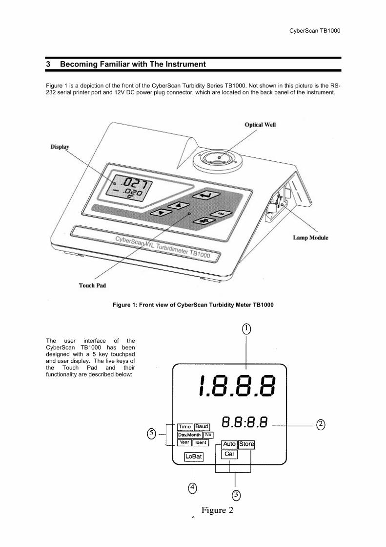
Figure 1 is a depiction of the front of the CyberScan Turbidity Series TB1000. Not shown in this picture is the RS-232 serial printer port and 12V DC power plug connector, which are located on the back panel of the instrument.
Figure 1: Front view of CyberScan Turbidity Meter TB1000 The user interface of the CyberScan TB1000 has been designed with a 5 key touchpad and user display. The five keys of the Touch Pad and their functionality are described below:

CyberScan TB1000
3
The ON/OFF key is used to turn the instrument on and off. The CAL key is used to enter, or exit, calibration mode. Both the ▲ and ▼ keys are used to set numerical values and to scroll through lists. The ENTER key stores value on the screen and/or causes the turbidity data to be output to the printer port when pressed. Figure 2 illustrates all the items that can appear on the display. The upper row of the display (1) is used for reporting the turbidity levels and to provide user guidance in the customer setting routine. The lower row of the display (2) is used to display the stored turbidity reading and to communicate error messages and user guidance. The display has several status indicators (3) which distinguish the operation of the instrument. In addition, the "LoBat" block (4) flashes when the batteries need to be replaced. Finally, several indicators (5) provide guidance when the customer setting routine is being used and when the calibration routine is being used.
4 Routine Operation
The CyberScan TB1000 measures and reports the turbidity of a sample in nephelometric turbidity units (NTU). NOTE: Nephelometric turbidity units (NTU’s) are numerically equivalent to Formazin turbidity units (FTU’s) (See
Glossary). Sections 4.1 and 4.2 describe how to use the CyberScan TB1000 under normal operating conditions. These sections include details on how to input certain customer selectable parameters and how to take normal, routine turbidity measurements using the CyberScan TB1000. 4.1 Grab Sample Measurement (Routine Measurement) The following steps describe how to measure the turbidity of a sample using the CyberScan TB1000: 1. Turn on the CyberScan TB1000 using ON key. The instrument will be in the normal mode (the "AUTO"
block should be illuminated). Allow instrument to warm up for at least 30 minutes. 2. Sample approximately 100 ml of the process stream as you would normally do for turbidity measurement. 3. Obtain a clean and dry sample cuvette. 4. Rinse the cuvette with approximately 20 ml of the sample water (2/3 of cuvette volume), capping the
cuvette with the black light shield (cuvette top) and inverting several times. Discard the 20ml of used sample and repeat the rinsing procedure two more times.
5. Completely fill the rinsed cuvette (from step 4) with the remaining portion (approximately 30 ml) of the grab sample and then cap the cuvette with the black light shield. Ensure that the outside of the cuvette is dry, clean and free from smudges** .
6. Place the cuvette in the CyberScan TB1000 and index the cuvette to the lowest reading (the displayed turbidity is continuously updated on the upper row of the display). Once the cuvette is indexed, the reading displayed on the CyberScan TB1000 display should be recorded as the sample turbidity (see Glossary for more information on indexing a cuvette).
** Any typical glass cleaner can be used along with a lint free cloth, or tissue, to clean the outside of the cuvette.
7. If you are measuring and comparing more than one sample, pressing ENTER key will display the latest reading (displayed on the lower row of the display). In addition, if you have selected printer output in the customer setup section, pressing ENTER key will output data to the RS232 port. Repeat steps 2 through 7 for all of your samples.
NOTE: The CyberScan TB1000 may display “- - -“ for a few seconds while it determines the correct reading. NOTE: An indication of “Or” (over-range) in the upper row of the display indicates that the standard in the sample
well is higher than 1000 NTU. WARNING: NEVER pour liquid directly into the sample well of the CyberScan TB1000, always use a cuvette.
The CyberScan TB1000 will accurately measure the turbidity of a sample using only cuvettes with the black light shield on the cuvettes provided or the optional pour through assembly.
CyberScan TB1000
4
4.2 Pour Through Sample Measurement (Optional Accessory) Install the pour through assembly and index it according to the instruction sheet that accompanies the assembly. The following steps describe how to measure the turbidity of a sample using the CyberScan TB1000 fitted with the optional pour through assembly: 1. Turn on the CyberScan TB1000. The instrument will be in the normal automatic mode (the "AUTO" block
should be illuminated). Allow instrument to warm up for at least 30 minutes. 2. Sample approximately 500 ml of the process stream as you would normally do for turbidity measurement. 3. Pour the complete 500 ml sample into the pour through assembly. Record the turbidity of the sample
displayed after the entire 500 ml sample has been poured into the assembly and the flow to drain has ceased, and after the reading has stabilized.
4. If you are measuring and comparing more than one sample, pressing ENTER key will store the reading (displayed on the lower row of the display). In addition, if you have selected printer output in the customer setup section pressing ENTER key will output data to RS232 port.
5. Repeat steps 2 through 4 for all of your samples.
The sample cuvette used in the pour through assembly is identical to the two standard sample cuvettes supplied with the CyberScan TB1000. Clean the cuvette on a periodic basis according to your experience with the type and turbidity of the sample found in your facility.
5 Calibration Procedures The CyberScan TB1000 Turbidimeter has been factory-calibrated using Eutech Instruments calibration standards that are traceable to the primary turbidity calibration standard, Formazin. It is possible to use the instrument directly out of the box. However, re-calibration of the instrument using the calibration set included is recommended to allow you to become familiar with the operation of the instrument and the calibration procedures. Eutech Instruments recommends that you use the following materials during calibration to achieve the accuracy stated in this manual: 1. De-ionized water filtered through a 0.2 µm filter, or 0.02 NTU Calibration Standard 2. 10.0 NTU Calibration Standard
3. 1000 NTU Calibration Standard Under normal conditions, re-calibration is recommended at least once every three months. You can select a predetermined calibration interval (see section 5.3) for automatic prompting for calibration: if you exceed the selected calibration interval, the "Cal" block will flash until the instrument is re-calibrated. NOTE: It is well known that diluted Formazin is unstable. If you choose to use Formazin to calibrate the CyberScan TB1000, ensure that you are using a fresh stock suspension of Formazin to achieve the accuracy quoted for the CyberScan TB1000. The Eutech Instruments calibration standards are more stable than Formazin and have a shelf life of 1 year. If you use the stable Eutech Instruments calibration standards to calibrate the instrument, review the expiration date to ensure that the standards have not expired.
NOTE: The CyberScan TB1000 must be re-calibrated after lamp replacement. 5.1 Indexing the Calibration Standard(s) The United States Environmental Protection Agency (US EPA) recommends that cuvettes used for instrument calibration or sample measurement be indexed. To comply with this recommendation, each Eutech Instruments calibration standard is supplied with an indexing ring and each CyberScan TB1000 is supplied with an indexing pin for quick and repeatable indexing of the calibration standard. The white indexing pin is installed on the collar ring around the optical well.

CyberScan TB1000
5
To index a calibration standard perform the following steps:
1. Slowly rotate the calibration standard one complete revolution (360°). 2. While rotating the standard, observe the CyberScan TB1000 and locate the cuvette position with the
lowest turbidity reading. 3. With the calibration standard positioned at the location having the lowest turbidity reading, install the
Indexing Ring over the black light shield on the standard so that the pointer of the Ring aligns with the Indexing Pin.
5.2 Calibration Procedure
Even though it is possible to calibrate the CyberScan TB1000 using any sequence of the prescribed calibration standards, to achieve the stated accuracy you must use the procedure below to calibrate instrument. 1. Press CAL key. Once this key is pushed the
“Ident” block and the “Cal” block will illuminate on the display.
2. The turbidity value displayed in the lower row of the display should read 1000 NTU. This is the first standard that must be used in calibration. Insert the 1000 NTU calibration standard into the sample well (see figure 3) by aligning the notch and the indexing pin (see section 5.1 if you have not already indexed the standard) and wait for the reading to stabilize.
3. Press ENTER key when the standard is in position. After the enter key has been pressed, the instrument will calibrate on the 1000 NTU level (the “Store” block will flash) and the upper row of the display should display 1000 NTU. The lower row of the display now shows that the 10.0 NTU calibration standard should be placed in the sample well for continuing calibration sequence.
4. Insert the indexed 10.0 NTU calibration standard into the sample well by aligning the notch and the indexing pin (see section 5.1 if you have not already indexed the standard) and wait for the reading to stabilize.
5. Press ENTER key when the standard is in position. After the enter key has been pressed, the instrument will calibrate on the 10.0 NTU level (the “Store” block will flash) and the upper row of the display should display 10.0 NTU. The lower row of the display now shows that the 0.02 NTU calibration standard should be placed in the sample well for continuing the calibration sequence and wait for the reading to stabilize.
6. Insert the indexed 0.02 NTU calibration standard into the sample well by aligning the notch and the indexing pin (see section 5.1 if you have not already indexed the standard).
7. Press ENTER key when the standard is in position. After the ENTER key has been pressed, the instrument will calibrate on the 0.02 NTU level. The instrument automatically exits out of the calibration mode and then returns to the normal automatic mode. The display should read 0.02 NTU since this is the turbidity level of the standard that is still in the sample well. At this point, you have calibrated the instrument so that it measures accurately across the full range of the instrument.
8. Proceed to use the instrument normally. NOTE: During calibration, the CyberScan TB1000 will perform some system self-diagnostics. Several error messages may be displayed. If there is an error, one of the four error messages E01, E02, E03, and E04 will be displayed in the lower row of the display (see section 7.2). NOTE: At any point in time during calibration, you can cycle through the required calibration points (0.02 NTU, 10 NTU, and 1000 NTU) by pressing either ▲ or ▼ keys to individually calibrate with a particular calibration standard. If you wish to exit the calibration mode you may do so at any time by simply pressing the CAL key. However, exiting the calibration process without completing the steps for calibration may cause the accuracy of the instrument to be diminished.

CyberScan TB1000
6
6 User Selectable Parameters The CyberScan TB1000 provides you the ability to customize your instrument according to your needs at any time during normal operation. This section describes how you can customize your instrument. NOTE: You cannot access any of the user selectable parameters during calibration. Enter the customer selectable parameter section of CyberScan TB1000 by simultaneously pressing ▲ key while holding down the ▼ key when the instrument is operating in the normal automatic mode. The "Year" block will be highlighted and the year will be displayed. NOTE: To skip the selection of any parameter, simply press ENTER key to continue on to the next section. 6.1 Setting the Year With the "Year" block highlighted and the year displayed, change the displayed year using ▲ or ▼ keys. When you have selected the proper year press ENTER key to accept the year. 6.2 Setting the Day and Month After pressing the ENTER key, the "Day.Month" block will be displayed and you will see two numbers on the lower row of the display. The number flashing corresponds to the month. Select the correct month by pressing ▲ or ▼ key to change the displayed month. When you have selected the proper month, press ENTER key. After pressing the ENTER key, the "Day.Month" block will still be displayed and the second number on the lower row of the display will be flashing: this number corresponds to the day of the month. Select the correct day by pressing ▲ or ▼ keys to change the displayed day. When you have selected the proper day, press the ENTER key. NOTE: The CyberScan TB1000 is year 2000 (Y2K) compliant and automatically adjusts for leap years. 6.3 Setting the Time After pressing the ENTER key, the "Time" block will be displayed and you will see the time displayed on the lower row of the display in 24 hour format. The number flashing corresponds to the hour. Select the correct hour by pressing ▲ or ▼ key to change the displayed hour. When you have selected the proper hour, press the ENTER key. After pressing the ENTER key, the" Time" block will still be displayed and the second number on the lower row of the display will be flashing: this number corresponds to minutes. Select the correct minutes level by pressing ▲ or ▼ key to change the displayed minutes. When you have selected the proper minutes level, press ENTER key. 6.4 Setting the Calibration Interval After pressing the ENTER key, the upper row of the display will have the letters “Int” printed in it. This corresponds to the calibration time interval. The number in the lower row of the display corresponds to the number of days that you wish to have between scheduled calibrations (default is 30 days). Select the desired number of days between scheduled calibrations by pressing ▲ or ▼ key to change the displayed day. In normal automatic mode, if you exceed this number of days between calibration, the "Cal" block will flash until you re-calibrate the instrument. When you have selected the desired calibration interval press ENTER key.
CyberScan TB1000
7
6.5 Setting the Printing Function After pressing the ENTER key, the upper row of the display will have the letters “Prt” printed in it. This feature allows you to turn the printing option on the instrument on or off. Select the desired printing action (on or off) by pressing ▲ or ▼ key. When you have selected the proper printing option, press ENTER key. If you selected to turn off the printing function, pressing ENTER key will return you back to the normal mode of the instrument. If, on the other hand, you chose to turn on the printing function, pressing ENTER key will cause the "Baud" block to be highlighted and you can select the correct baud rate for operation of your printer. Select the desired baud rate (1200, 2400, 4800, or 9600) by pressing ▲ or ▼ key to change the displayed baud rate. The other RS 232 parameters are fixed at 2 stop bits, 8 data bits and odd parity. Once you have selected the proper baud rate, press ENTER key. Pressing the ENTER key will return you back to the normal automatic mode of the instrument. By turning on the printing function, you have instructed the instrument to print out specific information. When ENTER key is pressed during the normal mode, information is output on the sample in the optical well (See Figure 4). This figure shows the information printed for four different samples. The format of the information is time, date and turbidity level. Also, a specific message will be printed out upon exit or completion of the calibration routine (See Figure 5). This printout shows all of the information that is pertinent to the calibration status of the instrument. 6.6 Completing Selectable Parameters You have now completed the customer selectable parameter section of the instrument. You can enter this menu at any time to re-set, or change any of the parameters.
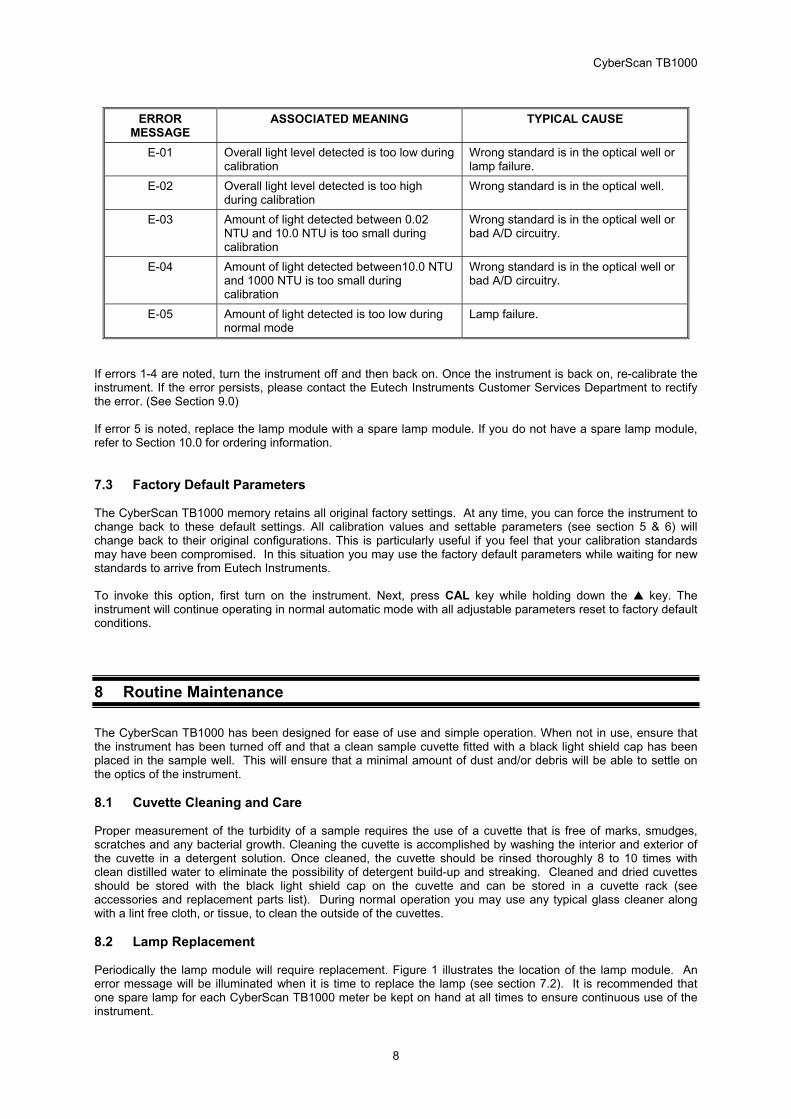
7 Troubleshooting 7.1 System Warning Message(s) Automatic warning messages are generated by the CyberScan TB1000 to provide you with specific diagnostic information about the instrument. These messages are for your use and do not reduce the performance of the instrument. 7.1.1 Flashing “Cal” block A flashing "Cal" block observed during normal automatic mode indicates that you should recalibrate your instrument. The factory default is 30 days. Eutech Instruments recommends calibration every 30 days. The flashing "Cal" block is only a warning and does not mean that the instrument will stop performing accurately. The "Cal" block will flash until you have recalibrated the instrument. 7.1.2 Flashing “LoBat” block A flashing “LoBat” block on the display indicates that the backup batteries need to be replaced. Under this condition, the parameters that are stored in memory (all of the user settable parameters and the instrument calibration) may be lost under conditions when power is not supplied to the instrument. See section 8.3 for instructions on replacing the batteries. 7.2 System Error Message(s) Error messages are generated by the CyberScan TB1000 when it detects problems with the instrument operation. When these messages are observed and if you do not understand the instructions shown below, contact the Eutech Instruments Customer Services department to determine a resolution to the problem. An error message is indicated by the instrument when an "E-0X" is displayed on the lower row of the display. The CyberScan TB1000 has five error codes, each assessing a different component or system of components in the instrument. The following table lists the error messages and their associated meanings.
CyberScan TB1000
8
ERROR
MESSAGE ASSOCIATED MEANING TYPICAL CAUSE
E-01 Overall light level detected is too low during calibration
Wrong standard is in the optical well or lamp failure.
E-02 Overall light level detected is too high during calibration
Wrong standard is in the optical well.
E-03 Amount of light detected between 0.02 NTU and 10.0 NTU is too small during calibration
Wrong standard is in the optical well or bad A/D circuitry.
E-04 Amount of light detected between10.0 NTU and 1000 NTU is too small during calibration
Wrong standard is in the optical well or bad A/D circuitry.
E-05 Amount of light detected is too low during normal mode
Lamp failure.
If errors 1-4 are noted, turn the instrument off and then back on. Once the instrument is back on, re-calibrate the instrument. If the error persists, please contact the Eutech Instruments Customer Services Department to rectify the error. (See Section 9.0) If error 5 is noted, replace the lamp module with a spare lamp module. If you do not have a spare lamp module, refer to Section 10.0 for ordering information. 7.3 Factory Default Parameters The CyberScan TB1000 memory retains all original factory settings. At any time, you can force the instrument to change back to these default settings. All calibration values and settable parameters (see section 5 & 6) will change back to their original configurations. This is particularly useful if you feel that your calibration standards may have been compromised. In this situation you may use the factory default parameters while waiting for new standards to arrive from Eutech Instruments. To invoke this option, first turn on the instrument. Next, press CAL key while holding down the ▲ key. The instrument will continue operating in normal automatic mode with all adjustable parameters reset to factory default conditions.
8 Routine Maintenance The CyberScan TB1000 has been designed for ease of use and simple operation. When not in use, ensure that the instrument has been turned off and that a clean sample cuvette fitted with a black light shield cap has been placed in the sample well. This will ensure that a minimal amount of dust and/or debris will be able to settle on the optics of the instrument. 8.1 Cuvette Cleaning and Care Proper measurement of the turbidity of a sample requires the use of a cuvette that is free of marks, smudges, scratches and any bacterial growth. Cleaning the cuvette is accomplished by washing the interior and exterior of the cuvette in a detergent solution. Once cleaned, the cuvette should be rinsed thoroughly 8 to 10 times with clean distilled water to eliminate the possibility of detergent build-up and streaking. Cleaned and dried cuvettes should be stored with the black light shield cap on the cuvette and can be stored in a cuvette rack (see accessories and replacement parts list). During normal operation you may use any typical glass cleaner along with a lint free cloth, or tissue, to clean the outside of the cuvettes. 8.2 Lamp Replacement Periodically the lamp module will require replacement. Figure 1 illustrates the location of the lamp module. An error message will be illuminated when it is time to replace the lamp (see section 7.2). It is recommended that one spare lamp for each CyberScan TB1000 meter be kept on hand at all times to ensure continuous use of the instrument.
CyberScan TB1000
9
Before replacing the lamp module ensure that the instrument is turned off. Once you have turned off the instrument, proceed with the following instructions: 1. Remove the lamp module from the instrument by squeezing the two side tabs on the module inward while
pulling the module out of the instrument. Pull the module away from the instrument until the in-line power connector is exposed (about 6-8 inches).
2. Unfasten the connector by holding on to the white in-line connector and pulling the in-line connector apart. When pulling the in-line connector apart, DO NOT hold on to the wires.
3. The new lamp module can now be connected to the instrument using the in-line power connector. 4. Feed the wire back into the instrument being careful that the wire does not get in the way of the lamp or
the lamp holder Z (on instrument). Make sure that the light bulb icon on the back of the lamp module is upright. Press the module into the instrument until you hear it click firmly into place.
NOTE: The side tabs may need to be pressed outward until they click to secure the new lamp module. 5. If the two-side tabs on the lamp module do not click the lamp module securely in place, check that the
power wire is not obstructing the lamp module. 6. Turn on the instrument and follow the instructions in section 4.1 to re-calibrate the instrument with the new
lamp module. The instrument must be re-calibrated after lamp module replacement. 7. Resume normal operation. 8.3 Battery Replacement The following instructions will guide you through the replacement of the batteries on the CyberScan TB1000. Throughout this procedure DO NOT unplug the instrument. If the instrument is unplugged during this procedure, all customer settings will be lost. 1. Turn the unit off. 2. Remove the lamp module by first pressing the side tabs inward and pulling the module out. Then unplug
the in-line lamp module connector by pulling the connector apart (see section 8.2 for complete details on lamp replacement/removal).
3. Place the instrument upside down on a soft surface. 4. Remove the five screws and pull the bottom half of the instrument case away from the top portion of the
instrument case (NOTE: there is a center screw on the instrument that is located under the instruction sheet).
5. Locate the two silver disc-shaped batteries in the separate battery holders on the left side closest to the front of the instrument. Remove these old batteries by prying them slightly upward and sliding them out of their holders.
6. Replace the old batteries with two coin-cell CR3032 batteries (Code No. EC-BATT3032). The positive side of the batteries should be against the clip on the holder.
7. Replace the bottom half of the case making sure that the lamp module connector is fed through the lamp module opening.
8. Replace the five screws, re-connect the lamp module to the instrument and insert the module into the lamp module opening. (See Section 8.2).
9. Re-calibrate the instrument (see section 5.0) and then resume normal operation. 10. Dispose of used batteries in accordance with all Federal, state and local regulations.
CyberScan TB1000
10
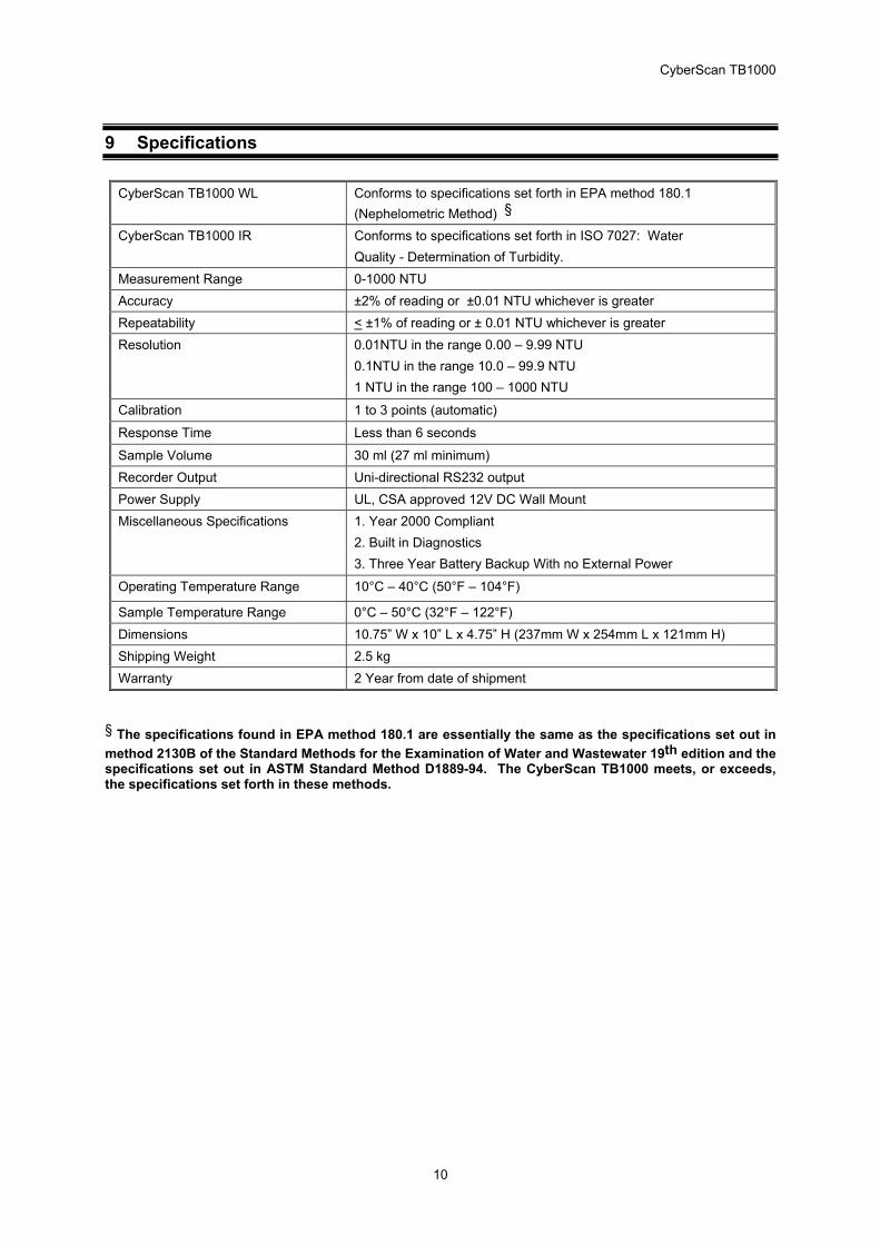
9 Specifications
CyberScan TB1000 WL Conforms to specifications set forth in EPA method 180.1 (Nephelometric Method) §
CyberScan TB1000 IR Conforms to specifications set forth in ISO 7027: Water Quality - Determination of Turbidity.
Measurement Range 0-1000 NTU Accuracy ±2% of reading or ±0.01 NTU whichever is greater Repeatability < ±1% of reading or ± 0.01 NTU whichever is greater Resolution 0.01NTU in the range 0.00 – 9.99 NTU
0.1NTU in the range 10.0 – 99.9 NTU 1 NTU in the range 100 – 1000 NTU
Calibration 1 to 3 points (automatic)
Response Time Less than 6 seconds
Sample Volume 30 ml (27 ml minimum) Recorder Output Uni-directional RS232 output Power Supply UL, CSA approved 12V DC Wall Mount Miscellaneous Specifications 1. Year 2000 Compliant
2. Built in Diagnostics 3. Three Year Battery Backup With no External Power
Operating Temperature Range 10°C – 40°C (50°F – 104°F)
Sample Temperature Range 0°C – 50°C (32°F – 122°F) Dimensions 10.75” W x 10” L x 4.75” H (237mm W x 254mm L x 121mm H) Shipping Weight 2.5 kg Warranty 2 Year from date of shipment
§ The specifications found in EPA method 180.1 are essentially the same as the specifications set out in method 2130B of the Standard Methods for the Examination of Water and Wastewater 19th edition and the specifications set out in ASTM Standard Method D1889-94. The CyberScan TB1000 meets, or exceeds, the specifications set forth in these methods.
CyberScan TB1000
11
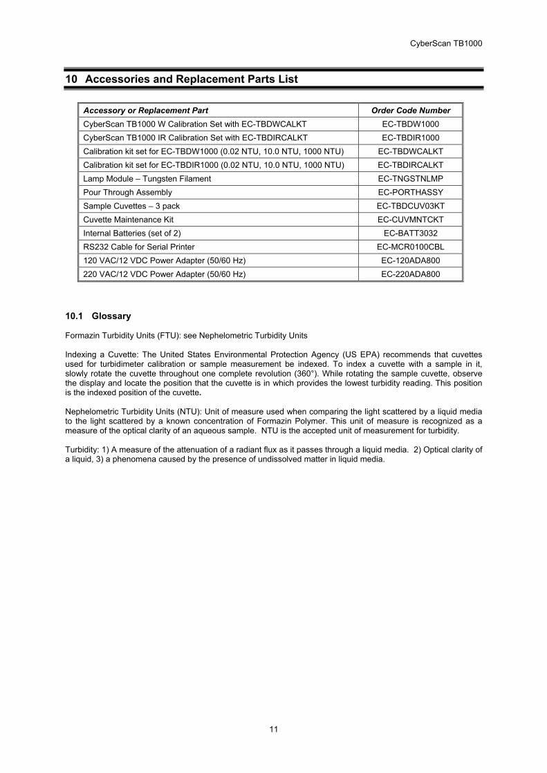
10 Accessories and Replacement Parts List
Accessory or Replacement Part Order Code Number CyberScan TB1000 W Calibration Set with EC-TBDWCALKT EC-TBDW1000 CyberScan TB1000 IR Calibration Set with EC-TBDIRCALKT EC-TBDIR1000 Calibration kit set for EC-TBDW1000 (0.02 NTU, 10.0 NTU, 1000 NTU) EC-TBDWCALKT Calibration kit set for EC-TBDIR1000 (0.02 NTU, 10.0 NTU, 1000 NTU) EC-TBDIRCALKT Lamp Module – Tungsten Filament EC-TNGSTNLMP Pour Through Assembly EC-PORTHASSY Sample Cuvettes – 3 pack EC-TBDCUV03KT Cuvette Maintenance Kit EC-CUVMNTCKT Internal Batteries (set of 2) EC-BATT3032 RS232 Cable for Serial Printer EC-MCR0100CBL 120 VAC/12 VDC Power Adapter (50/60 Hz) EC-120ADA800 220 VAC/12 VDC Power Adapter (50/60 Hz) EC-220ADA800
10.1 Glossary Formazin Turbidity Units (FTU): see Nephelometric Turbidity Units Indexing a Cuvette: The United States Environmental Protection Agency (US EPA) recommends that cuvettes used for turbidimeter calibration or sample measurement be indexed. To index a cuvette with a sample in it, slowly rotate the cuvette throughout one complete revolution (360°). While rotating the sample cuvette, observe the display and locate the position that the cuvette is in which provides the lowest turbidity reading. This position is the indexed position of the cuvette. Nephelometric Turbidity Units (NTU): Unit of measure used when comparing the light scattered by a liquid media to the light scattered by a known concentration of Formazin Polymer. This unit of measure is recognized as a measure of the optical clarity of an aqueous sample. NTU is the accepted unit of measurement for turbidity. Turbidity: 1) A measure of the attenuation of a radiant flux as it passes through a liquid media. 2) Optical clarity of a liquid, 3) a phenomena caused by the presence of undissolved matter in liquid media.

CyberScan TB1000
12
NOTES

CyberScan TB1000
13
Eutech Instruments Pte Ltd. Blk 55 Ayer Rajah Crescent #04-16 Singapore 139949 Tel: (65) 778 6876 Fax: (65) 773 0836 E-mail: [email protected] Web-site: http://www.eutechinst.com