Cyber Security Architecture Methodology for the Electric ... · part of a cyber security strategy....
64
Cyber Security Architecture Methodology for the Electric Sector 3002005942
Transcript of Cyber Security Architecture Methodology for the Electric ... · part of a cyber security strategy....
Cyber Security Architecture Methodology for the Electric Sector
3002005942

EPRI Project Manager
A. Lee
ELECTRIC POWER RESEARCH INSTITUTE 3420 Hillview Avenue, Palo Alto, California 94304-1338 ▪ PO Box 10412, Palo Alto, California 94303-0813 ▪ USA
800.313.3774 ▪ 650.855.2121 ▪ [email protected] ▪ www.epri.com
Cyber Security Architecture Methodology for the Electric Sector
3002005942
Technical Update, December 2015
DISCLAIMER OF WARRANTIES AND LIMITATION OF LIABILITIES THIS DOCUMENT WAS PREPARED BY THE ORGANIZATION(S) NAMED BELOW AS AN ACCOUNT OF WORK SPONSORED OR COSPONSORED BY THE ELECTRIC POWER RESEARCH INSTITUTE, INC. (EPRI). NEITHER EPRI, ANY MEMBER OF EPRI, ANY COSPONSOR, THE ORGANIZATION(S) BELOW, NOR ANY PERSON ACTING ON BEHALF OF ANY OF THEM:
(A) MAKES ANY WARRANTY OR REPRESENTATION WHATSOEVER, EXPRESS OR IMPLIED, (I) WITH RESPECT TO THE USE OF ANY INFORMATION, APPARATUS, METHOD, PROCESS, OR SIMILAR ITEM DISCLOSED IN THIS DOCUMENT, INCLUDING MERCHANTABILITY AND FITNESS FOR A PARTICULAR PURPOSE, OR (II) THAT SUCH USE DOES NOT INFRINGE ON OR INTERFERE WITH PRIVATELY OWNED RIGHTS, INCLUDING ANY PARTY'S INTELLECTUAL PROPERTY, OR (III) THAT THIS DOCUMENT IS SUITABLE TO ANY PARTICULAR USER'S CIRCUMSTANCE; OR
(B) ASSUMES RESPONSIBILITY FOR ANY DAMAGES OR OTHER LIABILITY WHATSOEVER (INCLUDING ANY CONSEQUENTIAL DAMAGES, EVEN IF EPRI OR ANY EPRI REPRESENTATIVE HAS BEEN ADVISED OF THE POSSIBILITY OF SUCH DAMAGES) RESULTING FROM YOUR SELECTION OR USE OF THIS DOCUMENT OR ANY INFORMATION, APPARATUS, METHOD, PROCESS, OR SIMILAR ITEM DISCLOSED IN THIS DOCUMENT.
REFERENCE HEREIN TO ANY SPECIFIC COMMERCIAL PRODUCT, PROCESS, OR SERVICE BY ITS TRADE NAME, TRADEMARK, MANUFACTURER, OR OTHERWISE, DOES NOT NECESSARILY CONSTITUTE OR IMPLY ITS ENDORSEMENT, RECOMMENDATION, OR FAVORING BY EPRI.
THE ELECTRIC POWER RESEARCH INSTITUTE (EPRI) PREPARED THIS REPORT.
This is an EPRI Technical Update report. A Technical Update report is intended as an informal report of continuing research, a meeting, or a topical study. It is not a final EPRI technical report.
NOTE For further information about EPRI, call the EPRI Customer Assistance Center at 800.313.3774 or e-mail [email protected].
Electric Power Research Institute, EPRI, and TOGETHER…SHAPING THE FUTURE OF ELECTRICITY are registered service marks of the Electric Power Research Institute, Inc.
Copyright © 2015 Electric Power Research Institute, Inc. All rights reserved.
This publication is a corporate document that should be cited in the literature in the following manner:
Cyber Security Architecture Methodology for the Electric Sector. EPRI, Palo Alto, CA: 2015. 3002005942.
iii
ACKNOWLEDGMENTS The Electric Power Research Institute (EPRI) prepared this report.
Principal Investigator A. Lee
This report describes research sponsored by EPRI.
EPRI acknowledges the collaboration of the following organizations for their interest and involvement:
• American Public Power Association (APPA) • Edison Electric Institute (EEI) • National Rural Electric Cooperative Association (NRECA) • Utilities Telecom Council (UTC)
EPRI also acknowledges the input from utilities who have provided valuable information to guide this report.

v
ABSTRACT Currently, the nation’s power system consists of both legacy and next-generation technologies. This includes devices that may be 30–50 years old, include no cyber security controls, and implement proprietary communication protocols and applications. Many of these legacy devices have significant computing and performance constraints that limit the cyber security controls that may be implemented. In contrast, the new technology may include modern information technology (IT) devices with commercially available applications and communication protocols. The new operations technology (OT) devices may also include commercially available applications and communications.
With this change in technology, utilities are exploring methods to better address the cyber security requirements. This includes prioritizing the systems, performing a cyber security risk assessment, and determining the impacts of a cyber security compromise. These activities are part of a cyber security strategy.
Another component of the cyber security strategy is a cyber security architecture. Currently, utilities have enterprise architecture diagrams, but they have not typically developed a security architecture.
This report includes a methodology for developing a security architecture that leverages existing architecture methodologies.
Keywords Attack surface Cyber security Security architecture Vulnerabilities

EXECUTIVE SUMMARY
This publication is a corporate document that should be cited in the literature in the following manner:
Cyber Security Architecture Methodology for the Electric Sector. EPRI, Palo Alto, CA: 2015. 3002005942.
Product ID: 3002005942 Cyber Security Architecture Methodology for the Electric Sector
PRIMARY AUDIENCE: Personnel responsible for cyber security
KEY RESEARCH QUESTION For grid modernization, increased interconnection in electric sector devices is required, and this will result in a larger attack surface that may be exploited by potential adversaries such as nation-states, terrorist organizations, malicious contractors, and disgruntled employees. A security architecture methodology needs to be developed to support cyber security risk management in this new environment.
RESEARCH OVERVIEW Typically, an enterprise architecture does not address cyber security—specifically, the overall attack surface, attack vectors, potential vulnerabilities, and applicable response strategies. The challenge is to develop a security architecture methodology that augments, rather than replaces, current enterprise architecture methodologies and is at a level that is useful to utilities. This report includes the first version of a cyber security architecture methodology that may be used by utilities for existing and planned system architectures. The objective is to provide a common methodology that may be used by utilities of all sizes, from large investor-owned utilities to smaller cooperatives and municipalities. EPRI is collaborating with other research efforts that are defining enterprise architecture methodologies to ensure that the security architecture methodology does not conflict with these other efforts.
KEY FINDINGS • Currently, there is no common security architecture methodology that is used
throughout the utility industry. • A security architecture diagram may be used in evaluating the current system
configuration and defining the target configuration. • A security architecture methodology is one tool of a security risk management
strategy. • A security architecture diagram may be used in the development and assessment of
an integrated security operations center and a common operating picture.
VALUE STATEMENT A security architecture methodology is one of the tools that can be used to assess the constantly changing threat and technology environments.
EXECUTIVE SUMMARY
Together...Shaping the Future of Electricity®
Electric Power Research Institute 3420 Hillview Avenue, Palo Alto, California 94304-1338 • PO Box 10412, Palo Alto, California 94303-0813 USA
800.313.3774 • 650.855.2121 • [email protected] • www.epri.com © 2015 Electric Power Research Institute (EPRI), Inc. All rights reserved. Electric Power Research Institute, EPRI, and
TOGETHER...SHAPING THE FUTURE OF ELECTRICITY are registered service marks of the Electric Power Research Institute, Inc.
HOW TO APPLY RESULTS As utilities modernize the grid, they will need to assess the architecture to identify potential vulnerabilities that may be exploited by an attacker and the appropriate response strategies. This can be a difficult task without the use of a security architecture methodology. Because the goal of this project is to develop a common methodology, participation in the project and providing input will ensure that the product is useful to utilities.
EPRI CONTACTS: Annabelle Lee, Senior Technical Executive, 202.293.6345, [email protected]
ix
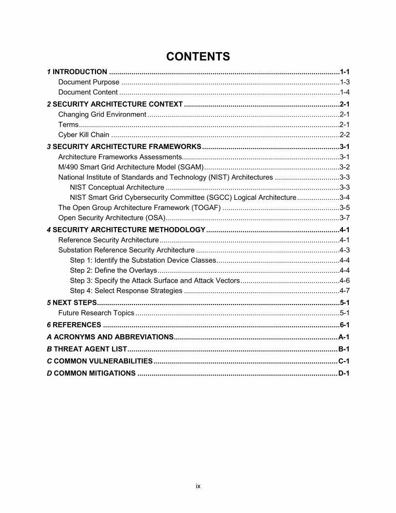
CONTENTS 1 INTRODUCTION ..................................................................................................................1-1
Document Purpose ............................................................................................................1-3 Document Content .............................................................................................................1-4
2 SECURITY ARCHITECTURE CONTEXT .............................................................................2-1 Changing Grid Environment ...............................................................................................2-1 Terms .................................................................................................................................2-1 Cyber Kill Chain .................................................................................................................2-2
3 SECURITY ARCHITECTURE FRAMEWORKS ....................................................................3-1 Architecture Frameworks Assessments..............................................................................3-1 M/490 Smart Grid Architecture Model (SGAM) ...................................................................3-2 National Institute of Standards and Technology (NIST) Architectures ................................3-3
NIST Conceptual Architecture ......................................................................................3-3 NIST Smart Grid Cybersecurity Committee (SGCC) Logical Architecture .....................3-4
The Open Group Architecture Framework (TOGAF) ..........................................................3-5 Open Security Architecture (OSA) ......................................................................................3-7
4 SECURITY ARCHITECTURE METHODOLOGY ..................................................................4-1 Reference Security Architecture .........................................................................................4-1 Substation Reference Security Architecture .......................................................................4-3
Step 1: Identify the Substation Device Classes .............................................................4-4 Step 2: Define the Overlays ..........................................................................................4-4 Step 3: Specify the Attack Surface and Attack Vectors .................................................4-6 Step 4: Select Response Strategies .............................................................................4-7
5 NEXT STEPS ........................................................................................................................5-1 Future Research Topics .....................................................................................................5-1
6 REFERENCES .....................................................................................................................6-1
A ACRONYMS AND ABBREVIATIONS ................................................................................. A-1
B THREAT AGENT LIST ........................................................................................................ B-1
C COMMON VULNERABILITIES ........................................................................................... C-1
D COMMON MITIGATIONS ................................................................................................... D-1

xi
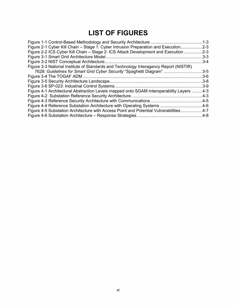
LIST OF FIGURES Figure 1-1 Control-Based Methodology and Security Architecture ...........................................1-3 Figure 2-1 Cyber Kill Chain – Stage 1: Cyber Intrusion Preparation and Execution ..................2-3 Figure 2-2 ICS Cyber Kill Chain – Stage 2: ICS Attack Development and Execution ...............2-3 Figure 3-1 Smart Grid Architecture Model ................................................................................3-3 Figure 3-2 NIST Conceptual Architecture .................................................................................3-4 Figure 3-3 National Institute of Standards and Technology Interagency Report (NISTIR)
7628: Guidelines for Smart Grid Cyber Security “Spaghetti Diagram” ................................3-5 Figure 3-4 The TOGAF ADM ...................................................................................................3-6 Figure 3-5 Security Architecture Landscape .............................................................................3-8 Figure 3-6 SP-023: Industrial Control Systems .........................................................................3-9 Figure 4-1 Architectural Abstraction Levels mapped onto SGAM Interoperability Layers .........4-3 Figure 4-2 Substation Reference Security Architecture ...........................................................4-3 Figure 4-3 Reference Security Architecture with Communications ...........................................4-5 Figure 4-4 Reference Substation Architecture with Operating Systems ...................................4-6 Figure 4-5 Substation Architecture with Access Point and Potential Vulnerabilities ..................4-7 Figure 4-6 Substation Architecture – Response Strategies ......................................................4-8

xiii
LIST OF TABLES Table B-1 Threat Agent List .................................................................................................... B-1 Table C-1 Common Vulnerabilities .......................................................................................... C-1 Table D-1 Common Mitigations ............................................................................................... D-1


1-1
1 INTRODUCTION Currently, the nation’s power system consists of both legacy and next generation technologies. This includes devices that may be 30-50 years old, include no cyber security controls and implement proprietary communication protocols and applications. Many of these legacy devices have significant computing and performance constraints that limit the cyber security controls that may be implemented. In contrast, the new technology may include modern information technology (IT) devices with commercially available applications and communication protocols. The new operations technology (OT) devices may also include commercially available applications and communications. To utilize this new technology, increased interconnection is required with the applicable cyber security controls implemented to address this larger attack surface that may be exploited by potential adversaries such as nation-states, terrorist organizations, malicious contractors, and disgruntled employees. The challenge and complexity of addressing cyber security risks has increased in part because the technology landscape and threat environment are constantly changing.
Each utility should develop and implement an overall risk management strategy that includes a cyber security risk strategy. The cyber security strategy may need to be tailored to the OT environment because of the performance and computing constraints referenced above. Another difference between IT and OT is that the primary security objectives for OT systems are availability and integrity, with confidentiality third. The primary security objectives for IT systems are confidentiality and integrity and availability third. This difference will impact the risk assessment and the specific security requirements that are selected.
An enterprise architecture may be included as one component of a risk assessment package. The architecture identifies, for example, the hardware, software, applications, and data that are included in the system. The architecture may be represented in several forms, for example, as a diagram and/or a list of applicable standards. An architecture framework methodology should be defined at the enterprise level to ensure consistency of the architectures developed throughout the organization. If diagrams are developed, they may be used to document the current or baseline system and the target system. One of the difficulties is that these enterprise diagrams can take significant time to create and can be very complex. As a result, they may not be maintained, thus reducing their usefulness.
Typically, an enterprise architecture does not address cyber security, specifically, the overall attack surface, attack vectors, potential vulnerabilities, and applicable response strategies. Alternatively, cyber security is documented in policies and procedures that are defined at the organization level. At the system level, these policies and procedures should be tailored and specifications developed.
1-2
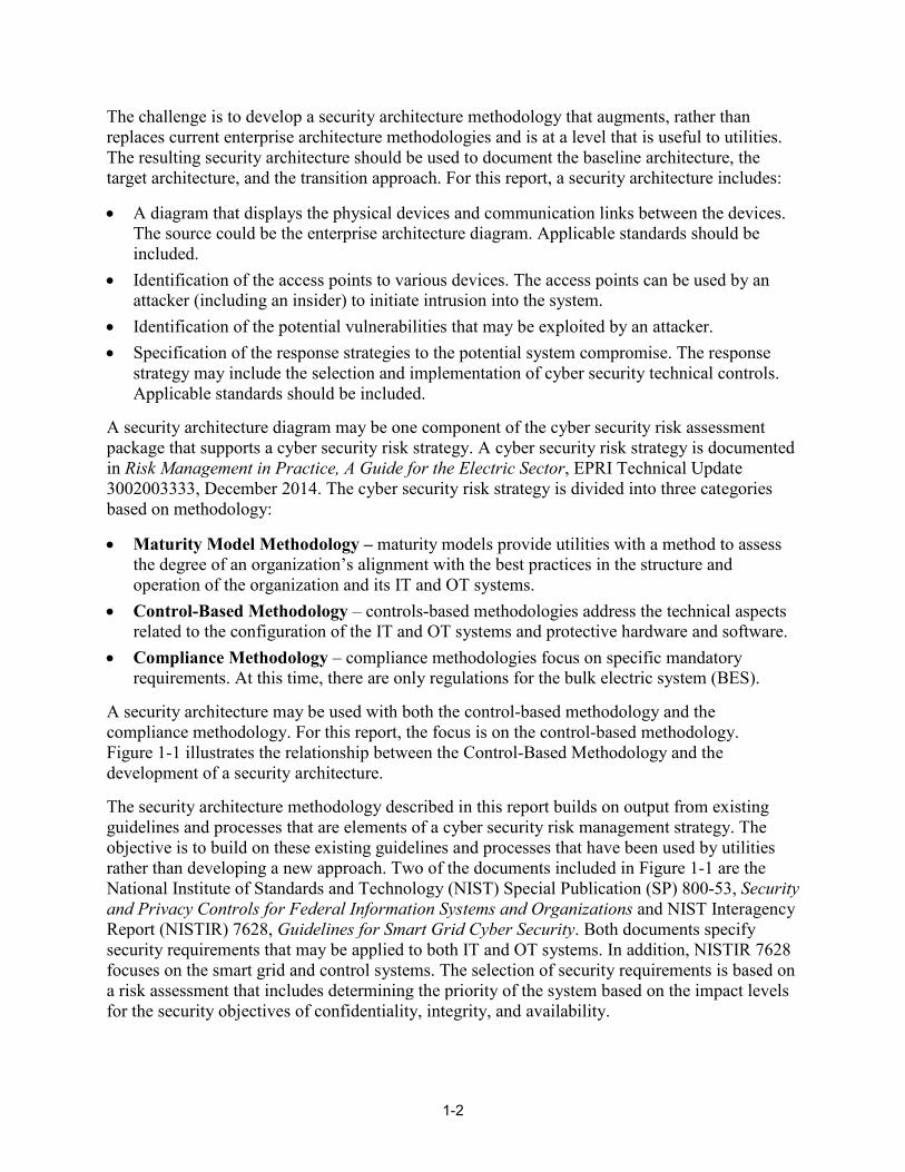
The challenge is to develop a security architecture methodology that augments, rather than replaces current enterprise architecture methodologies and is at a level that is useful to utilities. The resulting security architecture should be used to document the baseline architecture, the target architecture, and the transition approach. For this report, a security architecture includes:
• A diagram that displays the physical devices and communication links between the devices. The source could be the enterprise architecture diagram. Applicable standards should be included.
• Identification of the access points to various devices. The access points can be used by an attacker (including an insider) to initiate intrusion into the system.
• Identification of the potential vulnerabilities that may be exploited by an attacker. • Specification of the response strategies to the potential system compromise. The response
strategy may include the selection and implementation of cyber security technical controls. Applicable standards should be included.
A security architecture diagram may be one component of the cyber security risk assessment package that supports a cyber security risk strategy. A cyber security risk strategy is documented in Risk Management in Practice, A Guide for the Electric Sector, EPRI Technical Update 3002003333, December 2014. The cyber security risk strategy is divided into three categories based on methodology:
• Maturity Model Methodology – maturity models provide utilities with a method to assess the degree of an organization’s alignment with the best practices in the structure and operation of the organization and its IT and OT systems.
• Control-Based Methodology – controls-based methodologies address the technical aspects related to the configuration of the IT and OT systems and protective hardware and software.
• Compliance Methodology – compliance methodologies focus on specific mandatory requirements. At this time, there are only regulations for the bulk electric system (BES).
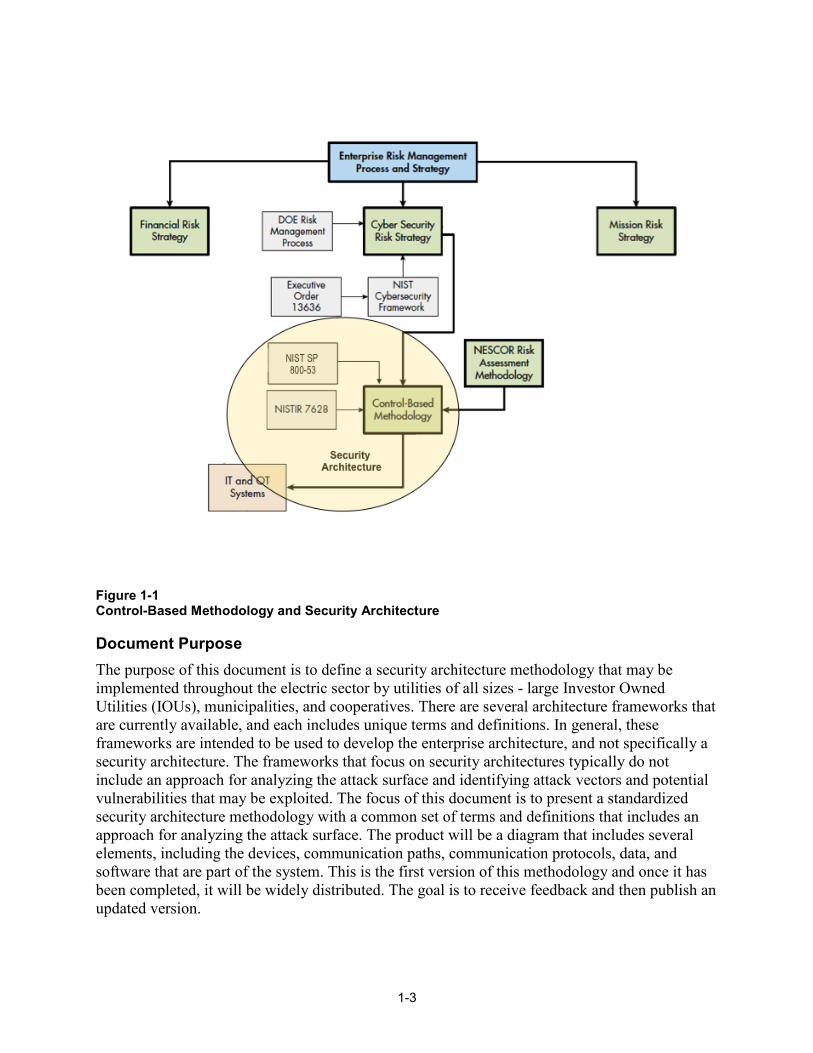
A security architecture may be used with both the control-based methodology and the compliance methodology. For this report, the focus is on the control-based methodology. Figure 1-1 illustrates the relationship between the Control-Based Methodology and the development of a security architecture.
The security architecture methodology described in this report builds on output from existing guidelines and processes that are elements of a cyber security risk management strategy. The objective is to build on these existing guidelines and processes that have been used by utilities rather than developing a new approach. Two of the documents included in Figure 1-1 are the National Institute of Standards and Technology (NIST) Special Publication (SP) 800-53, Security and Privacy Controls for Federal Information Systems and Organizations and NIST Interagency Report (NISTIR) 7628, Guidelines for Smart Grid Cyber Security. Both documents specify security requirements that may be applied to both IT and OT systems. In addition, NISTIR 7628 focuses on the smart grid and control systems. The selection of security requirements is based on a risk assessment that includes determining the priority of the system based on the impact levels for the security objectives of confidentiality, integrity, and availability.
1-3
Figure 1-1 Control-Based Methodology and Security Architecture
Document Purpose The purpose of this document is to define a security architecture methodology that may be implemented throughout the electric sector by utilities of all sizes - large Investor Owned Utilities (IOUs), municipalities, and cooperatives. There are several architecture frameworks that are currently available, and each includes unique terms and definitions. In general, these frameworks are intended to be used to develop the enterprise architecture, and not specifically a security architecture. The frameworks that focus on security architectures typically do not include an approach for analyzing the attack surface and identifying attack vectors and potential vulnerabilities that may be exploited. The focus of this document is to present a standardized security architecture methodology with a common set of terms and definitions that includes an approach for analyzing the attack surface. The product will be a diagram that includes several elements, including the devices, communication paths, communication protocols, data, and software that are part of the system. This is the first version of this methodology and once it has been completed, it will be widely distributed. The goal is to receive feedback and then publish an updated version.
1-4
Document Content This document contains the following sections:
• Section 1: Introduction • Section 2: Security Architecture Context • Section 3: Security Architecture Concepts and Framework • Section 4: Security Architecture Methodology • Section 5: Next Steps
2-1
2 SECURITY ARCHITECTURE CONTEXT Utilities are facing many challenges in addressing cyber security for the existing and planned grid. As described above, the current grid architecture includes both new and legacy technology and commercially-available and proprietary solutions. From a cyber security perspective, the goal is to manage rather than avoid risk. This report describes a security architecture methodology that takes as the base the existing enterprise architecture, risk management approach, and cyber security strategy.
Changing Grid Environment The technology environment is constantly changing and this is impacting the electric sector and cyber security. In general, these changes are making the cyber security environment more complex and the attack surface larger. Some of these changes are listed below:
• With the deployment of distributed energy resources (DER), utilities are modifying the overall grid architecture – and this requires considering centralized versus distributed application of technology. With distributed applications, remote access to substations, control centers, and devices is increasing. In general, remote access to OT systems is through an enterprise IT system.
• Many utilities are considering consolidating their IT security operations, OT security operations, and physical security in an integrated security operations center (ISOC) to address the new cyber security environment.
• Deployment of cloud computing. Cloud computing provides for network access to a shared pool of configurable computing resources (e.g., networks, servers, storage, applications, and services).
• Grid modernization. With the increased deployment of digital technology and capabilities, insiders have increased functionality and access to data. With increased privileges, insiders have greater opportunity to compromise systems. Addressing the insider threat and determining how to represent them in the security architecture still needs to be determined.
All of these changes should be reflected in the security architecture that must be adaptable and resilient while ensuring reliability.
Terms Section 1 of this report includes an overview of the terms enterprise architecture and security architecture. Included below are architecture terms and concepts from referenced documents. They are included as background and were used in developing the scope of this project. Note: this is not intended to be a comprehensive review of the literature.
There are several definitions related to an architecture. The definition of an architecture used in ANSI/IEEE Std. 1471-2000 is:
"The fundamental organization of a system, embodied in its components, their relationships to each other and the environment, and the principles governing its design and evolution."

2-2
The Open Group Architecture Framework (TOGAF) does not strictly adhere to the ANSI/IEEE Std. 1471-2000 terminology. In TOGAF, "architecture" has two meanings depending upon its contextual usage:
1. A formal description of a system, or a detailed plan of the system at component level to guide its implementation. 2. The structure of components, their inter-relationships, and the principles and guidelines governing their design and evolution over time.
There are two other concepts applicable to an architecture, as defined by TOGAF.
An architecture framework is a tool that can be used for developing a broad range of different architectures. It should describe a method for designing an information system in terms of a set of building blocks, and for showing how the building blocks fit together. It should contain a set of tools and provide a common vocabulary. It should also include a list of recommended standards and compliant products that can be used to implement the building blocks.
An architecture description is a formal description of an information system, organized in a way that supports reasoning about the structural properties of the system. It defines the components or building blocks that make up the overall information system, and provides a plan from which products can be procured, and systems developed, that will work together to implement the overall system.
According to the ISO/IEC/IEEE 42010-2011 standard:
An architecture framework includes:
Conventions, principles and practices for the description of architectures established within a specific domain of application and/or community of stakeholders.
An architecture description is a work product used to express an architecture.
This report does not include architecture frameworks or descriptions.
Cyber Kill Chain One of the major challenges for the electric sector is addressing the constantly changing threat environment. Many of the OT devices have life cycles of 30 to 40 years, and utilities will be required to upgrade/modify the embedded software and firmware. In addition, commercially available communication protocols, applications, and operating systems need to be patched for new vulnerabilities. Finally, zero day vulnerabilities may be exploited by attackers prior to the deployment of patches. Utilities need to understand the attack process to develop and implement mitigation strategies.
2-3
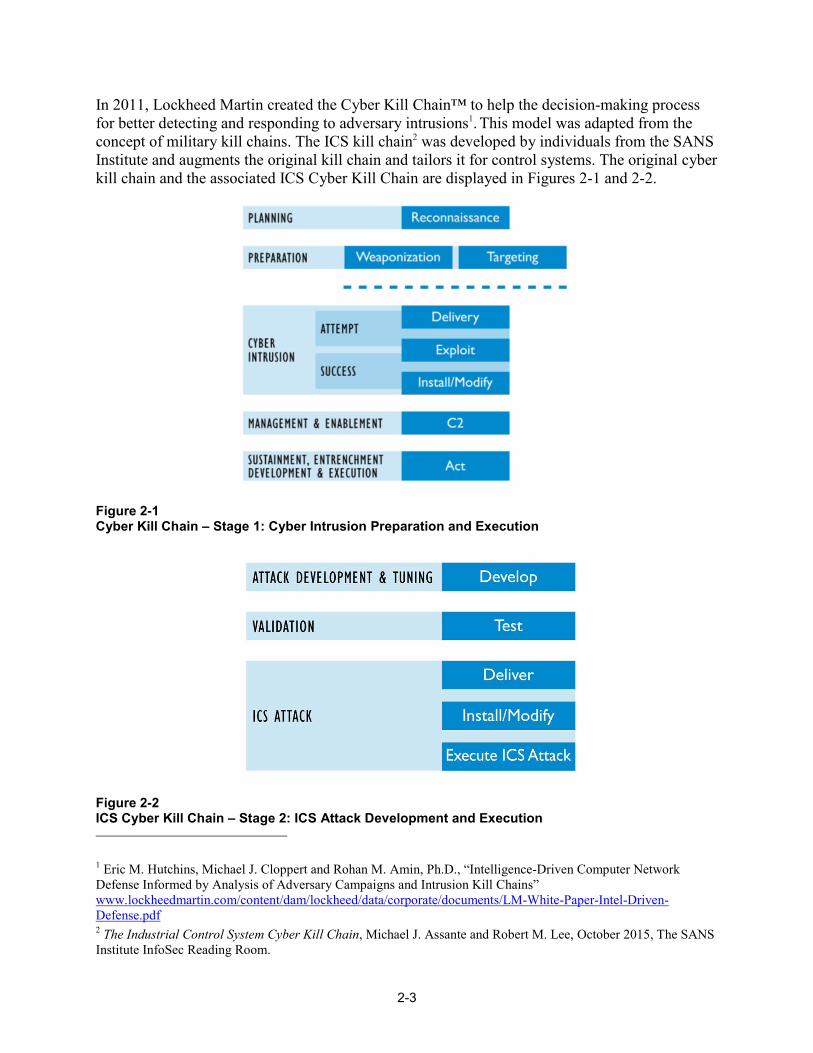
In 2011, Lockheed Martin created the Cyber Kill Chain™ to help the decision-making process for better detecting and responding to adversary intrusions1. This model was adapted from the concept of military kill chains. The ICS kill chain2 was developed by individuals from the SANS Institute and augments the original kill chain and tailors it for control systems. The original cyber kill chain and the associated ICS Cyber Kill Chain are displayed in Figures 2-1 and 2-2.
Figure 2-1 Cyber Kill Chain – Stage 1: Cyber Intrusion Preparation and Execution
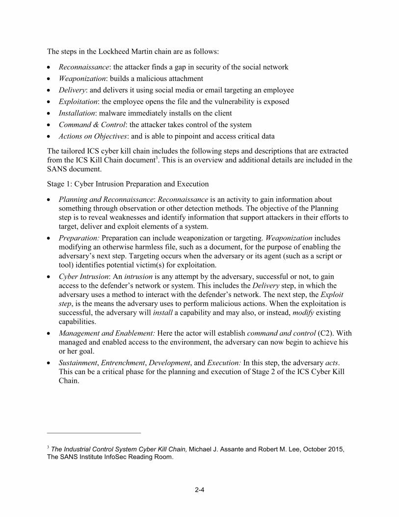
Figure 2-2 ICS Cyber Kill Chain – Stage 2: ICS Attack Development and Execution 1 Eric M. Hutchins, Michael J. Cloppert and Rohan M. Amin, Ph.D., “Intelligence-Driven Computer Network Defense Informed by Analysis of Adversary Campaigns and Intrusion Kill Chains” www.lockheedmartin.com/content/dam/lockheed/data/corporate/documents/LM-White-Paper-Intel-Driven-Defense.pdf 2 The Industrial Control System Cyber Kill Chain, Michael J. Assante and Robert M. Lee, October 2015, The SANS Institute InfoSec Reading Room.
2-4
The steps in the Lockheed Martin chain are as follows:
• Reconnaissance: the attacker finds a gap in security of the social network • Weaponization: builds a malicious attachment • Delivery: and delivers it using social media or email targeting an employee • Exploitation: the employee opens the file and the vulnerability is exposed • Installation: malware immediately installs on the client • Command & Control: the attacker takes control of the system • Actions on Objectives: and is able to pinpoint and access critical data
The tailored ICS cyber kill chain includes the following steps and descriptions that are extracted from the ICS Kill Chain document3. This is an overview and additional details are included in the SANS document.
Stage 1: Cyber Intrusion Preparation and Execution
• Planning and Reconnaissance: Reconnaissance is an activity to gain information about something through observation or other detection methods. The objective of the Planning step is to reveal weaknesses and identify information that support attackers in their efforts to target, deliver and exploit elements of a system.
• Preparation: Preparation can include weaponization or targeting. Weaponization includes modifying an otherwise harmless file, such as a document, for the purpose of enabling the adversary’s next step. Targeting occurs when the adversary or its agent (such as a script or tool) identifies potential victim(s) for exploitation.
• Cyber Intrusion: An intrusion is any attempt by the adversary, successful or not, to gain access to the defender’s network or system. This includes the Delivery step, in which the adversary uses a method to interact with the defender’s network. The next step, the Exploit step, is the means the adversary uses to perform malicious actions. When the exploitation is successful, the adversary will install a capability and may also, or instead, modify existing capabilities.
• Management and Enablement: Here the actor will establish command and control (C2). With managed and enabled access to the environment, the adversary can now begin to achieve his or her goal.
• Sustainment, Entrenchment, Development, and Execution: In this step, the adversary acts. This can be a critical phase for the planning and execution of Stage 2 of the ICS Cyber Kill Chain.
3 The Industrial Control System Cyber Kill Chain, Michael J. Assante and Robert M. Lee, October 2015, The SANS Institute InfoSec Reading Room.
2-5
Stage 2: ICS Attack Development and Execution
• Attack Development and Tuning phase. The aggressor develops a new capability tailored to affect a specific ICS implementation and for the desired impact. This development will most likely take place through exfiltrated data.
• Validation: Here, the attacker must Test his or her capability on similar or identically configured systems if the capability is to have any meaningful and reliable impact.
• ICS Attack: the adversary will deliver the capability, install it or modify existing system functionality, and then execute the attack.


3-1
3 SECURITY ARCHITECTURE FRAMEWORKS There are several architecture frameworks that are used throughout the world. These generally do not focus specifically on the electric sector and cyber security. Rather, they are more general. Included in this section is an assessment of the architecture frameworks and their applicability to this project.
The four architecture frameworks included below may be used in the development of or input to a security architecture. TOGAF and SGAM are frameworks and tools for developing enterprise architectures, including architecture diagrams. The architecture diagrams developed using TOGAF, at the enterprise level, and SGAM for the smart grid, will be very complex and detailed. OSA includes standardized icons and generic architecture diagrams. The SGCC is a reference diagram and may be used in the selection of security responses. None of these frameworks include attack vectors and responses.
Architecture Frameworks Assessments Following is a summary of each framework.
• TOGAF: Widely used in the development of implemented IT enterprise architectures. TOGAF focuses on the development of a logical, rather than a physical architecture.
• SGAM: Used throughout Europe and referenced in other documents. SGAM is specific to the smart grid and may be used to develop the current and target architectures for specific systems. The SGAM may be used to identify functional and non-functional requirements and applicable standards.
• SGCC spaghetti diagram: The diagram is referenced worldwide, is specific to the smart grid, and represents a logical security architecture. This is primarily a reference diagram rather than a tool to develop a security architecture.
• OSA: The security architecture patterns [diagrams] primarily focus on the IT environment and are not specific to the smart grid. Also, the patterns are more abstract, rather than implementation specific, architecture diagrams.
As stated earlier, the focus of this report is establishing a security architecture methodology that includes the attack surface, attack vectors, potential vulnerabilities that may be exploited, and potential mitigation strategies. The analysis of the attack surface may be considered in the development of the above security architectures, but it is not the primary objective.
3-2
M/490 Smart Grid Architecture Model (SGAM) In 2011, the European Commission published Mandate M/490, Standardization Mandate to European Standardisation Organisations (ESOs) to support European Smart Grid deployment. As stated in the mandate:
The objective of this mandate is to develop or update a set of consistent standards within a common European framework that integrating a variety of digital computing and communication technologies and electrical architectures, and associated processes and services, that will achieve interoperability and will enable or facilitate the implementation in Europe of the different high level Smart Grid services and functionalities as defined by the Smart Grid Task Force that will be flexible enough to accommodate future developments.
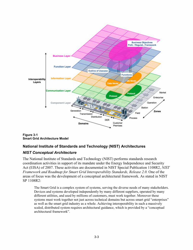
In support of this mandate, an overall architecture called the Smart Grid Architecture Model (SGAM) was developed by The European Committee for Standardisation (CEN), The European Committee for Electrotechnical Standardization (CENELEC), and The European Telecommunications Standards Institute (ETSI). Although several Smart Grid architectures were available, they represented individual stakeholders’ points of view. The difficulty was that there was no common presentation schema or framework that would allow various stakeholders to map their individual perspectives in a common view. The SGAM is based on existing approaches4 and incorporates the different perspectives and methodologies regarding the conceptualization of Smart Grids. The SGAM comprises three core viewpoints - layers, domains, and zones and supports a holistic view on architecture. It also5 provides a generic technology neutral view of Smart Grids that can be used to illustrate various power system architectures. Figure 3-1 is the SGAM.
4 IEC: 62357 Second Edition. TC 57 Architecture – Part 1: Reference Architecture for TC 57 – Draft (2009); IEC 61968-100 (Draft): Application Integration at electric utilities – System Interfaces for distribution management – Part 100: Implementation Profiles for IEC 61968 (2011); and NIST Framework and Roadmap for Smart Grid Interoperability Standards (2010). 5 Mathias Uslar, Michael Spect, et al, Standardization in Smart Grids – Introduction to IT-Related Methodologies, Architectures and Standards, 2013.
3-3
Figure 3-1 Smart Grid Architecture Model
National Institute of Standards and Technology (NIST) Architectures NIST Conceptual Architecture The National Institute of Standards and Technology (NIST) performs standards research coordination activities in support of its mandate under the Energy Independence and Security Act (EISA) of 2007. These activities are documented in NIST Special Publication 1108R2, NIST Framework and Roadmap for Smart Grid Interoperability Standards, Release 2.0. One of the areas of focus was the development of a conceptual architectural framework. As stated in NIST SP 1108R2:
The Smart Grid is a complex system of systems, serving the diverse needs of many stakeholders. Devices and systems developed independently by many different suppliers, operated by many different utilities, and used by millions of customers, must work together. Moreover these systems must work together not just across technical domains but across smart grid “enterprises” as well as the smart grid industry as a whole. Achieving interoperability in such a massively scaled, distributed system requires architectural guidance, which is provided by a “conceptual architectural framework”.
3-4
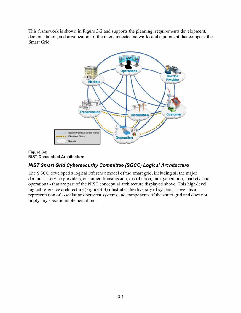
This framework is shown in Figure 3-2 and supports the planning, requirements development, documentation, and organization of the interconnected networks and equipment that compose the Smart Grid.
Figure 3-2 NIST Conceptual Architecture
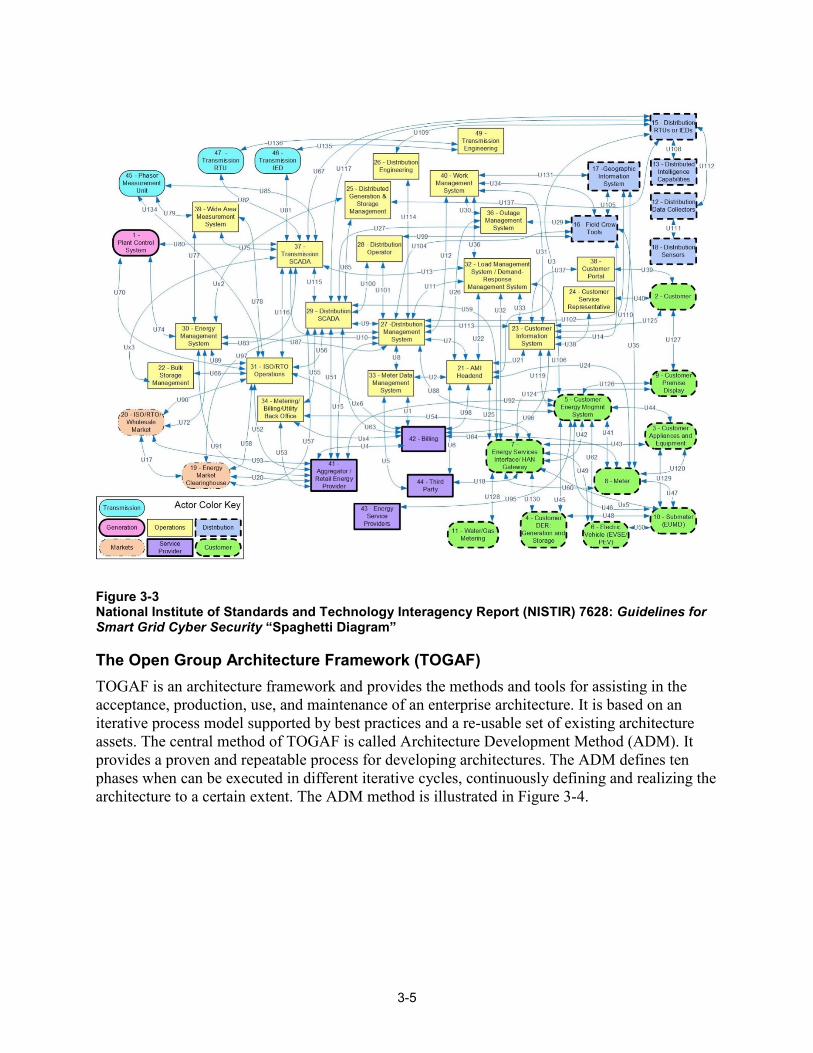
NIST Smart Grid Cybersecurity Committee (SGCC) Logical Architecture The SGCC developed a logical reference model of the smart grid, including all the major domains - service providers, customer, transmission, distribution, bulk generation, markets, and operations - that are part of the NIST conceptual architecture displayed above. This high-level logical reference architecture (Figure 3-3) illustrates the diversity of systems as well as a representation of associations between systems and components of the smart grid and does not imply any specific implementation.
3-5
Figure 3-3 National Institute of Standards and Technology Interagency Report (NISTIR) 7628: Guidelines for Smart Grid Cyber Security “Spaghetti Diagram”
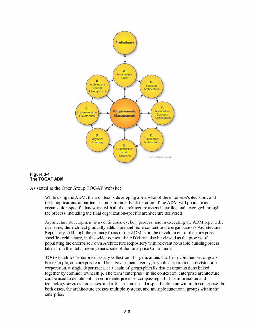
The Open Group Architecture Framework (TOGAF) TOGAF is an architecture framework and provides the methods and tools for assisting in the acceptance, production, use, and maintenance of an enterprise architecture. It is based on an iterative process model supported by best practices and a re-usable set of existing architecture assets. The central method of TOGAF is called Architecture Development Method (ADM). It provides a proven and repeatable process for developing architectures. The ADM defines ten phases when can be executed in different iterative cycles, continuously defining and realizing the architecture to a certain extent. The ADM method is illustrated in Figure 3-4.
3-6
Figure 3-4 The TOGAF ADM
As stated at the OpenGroup TOGAF website:
While using the ADM, the architect is developing a snapshot of the enterprise's decisions and their implications at particular points in time. Each iteration of the ADM will populate an organization-specific landscape with all the architecture assets identified and leveraged through the process, including the final organization-specific architecture delivered.
Architecture development is a continuous, cyclical process, and in executing the ADM repeatedly over time, the architect gradually adds more and more content to the organization's Architecture Repository. Although the primary focus of the ADM is on the development of the enterprise-specific architecture, in this wider context the ADM can also be viewed as the process of populating the enterprise's own Architecture Repository with relevant re-usable building blocks taken from the "left", more generic side of the Enterprise Continuum.
TOGAF defines "enterprise" as any collection of organizations that has a common set of goals. For example, an enterprise could be a government agency, a whole corporation, a division of a corporation, a single department, or a chain of geographically distant organizations linked together by common ownership. The term "enterprise" in the context of "enterprise architecture" can be used to denote both an entire enterprise - encompassing all of its information and technology services, processes, and infrastructure - and a specific domain within the enterprise. In both cases, the architecture crosses multiple systems, and multiple functional groups within the enterprise.
3-7
The purpose of enterprise architecture is to optimize across the enterprise the often fragmented legacy of processes (both manual and automated) into an integrated environment that is responsive to change and supportive of the delivery of the business strategy.
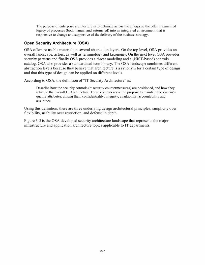
Open Security Architecture (OSA) OSA offers re-usable material on several abstraction layers. On the top level, OSA provides an overall landscape, actors, as well as terminology and taxonomy. On the next level OSA provides security patterns and finally OSA provides a threat modeling and a (NIST-based) controls catalog. OSA also provides a standardized icon library. The OSA landscape combines different abstraction levels because they believe that architecture is a synonym for a certain type of design and that this type of design can be applied on different levels.
According to OSA, the definition of “IT Security Architecture” is:
Describe how the security controls (= security countermeasures) are positioned, and how they relate to the overall IT Architecture. These controls serve the purpose to maintain the system’s quality attributes, among them confidentiality, integrity, availability, accountability and assurance.
Using this definition, there are three underlying design architectural principles: simplicity over flexibility, usability over restriction, and defense in depth.
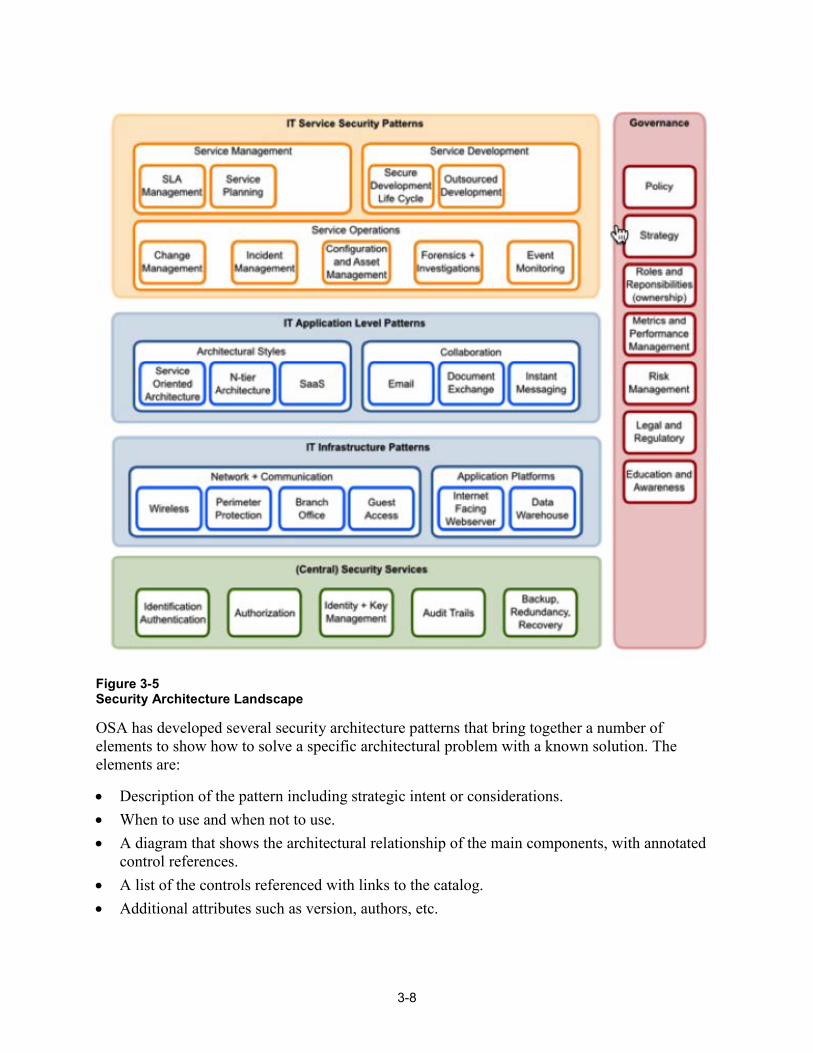
Figure 3-5 is the OSA developed security architecture landscape that represents the major infrastructure and application architecture topics applicable to IT departments.
3-8
Figure 3-5 Security Architecture Landscape
OSA has developed several security architecture patterns that bring together a number of elements to show how to solve a specific architectural problem with a known solution. The elements are:
• Description of the pattern including strategic intent or considerations. • When to use and when not to use. • A diagram that shows the architectural relationship of the main components, with annotated
control references. • A list of the controls referenced with links to the catalog. • Additional attributes such as version, authors, etc.
3-9
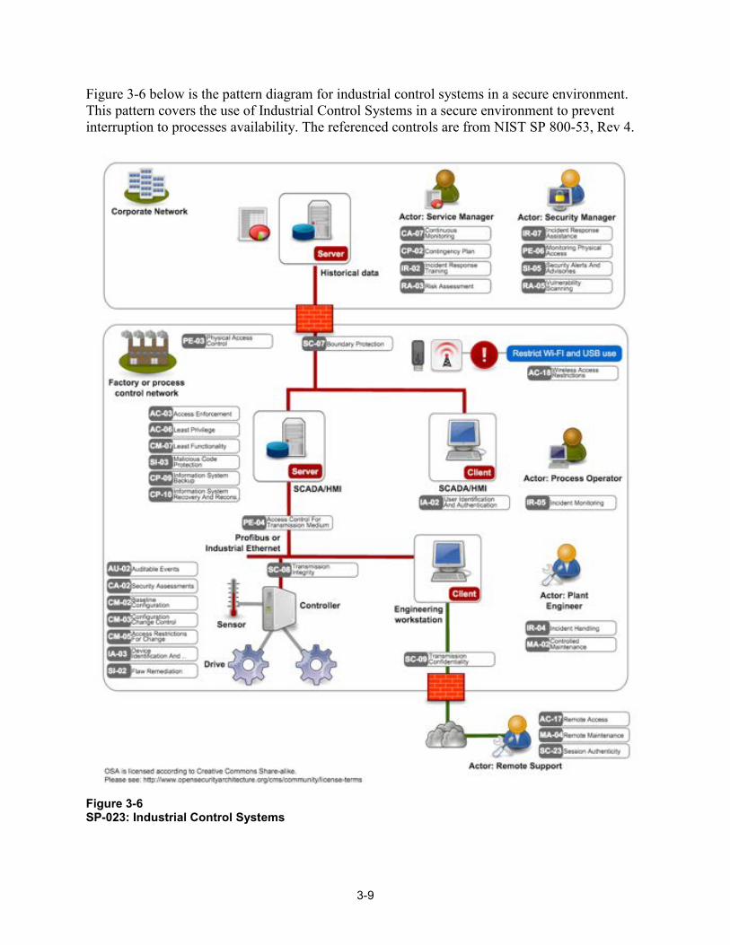
Figure 3-6 below is the pattern diagram for industrial control systems in a secure environment. This pattern covers the use of Industrial Control Systems in a secure environment to prevent interruption to processes availability. The referenced controls are from NIST SP 800-53, Rev 4.
Figure 3-6 SP-023: Industrial Control Systems

4-1
4 SECURITY ARCHITECTURE METHODOLOGY Based on a risk assessment strategy, the systems should be prioritized and the security objectives of confidentiality, integrity, and availability specified for each system. A security architecture should address the requirements and potential risks for each system that is implemented in a specific operational environment. The security architecture should also identify where to apply security controls and applicable standards/guidelines. A security architecture should be overlaid on an existing system/enterprise architecture that may include, for example, the various devices, communications links, communications protocols, operating systems, applications, and data. The security architecture should augment the existing architecture and include the attack vectors, potential vulnerabilities, and mitigation strategies. Output from a cyber kill chain analysis can be used in developing the target security architecture.
As described previously, the development of a security architecture should be one component of an overall cyber security risk management strategy and should facilitate the business risk exposure objectives. The security architecture may be used as input to evaluating the likelihood and impacts of security threats and vulnerabilities. A security architecture can be developed for the current system and for the target system. These security architectures can then be used to:
• Identify cyber security gaps and mitigation strategies to address these gaps, • Perform a cyber kill chain analysis, • Assess the operational implementation, • Ensure that the overall cyber security risk management strategy is mirrored in the mitigation
strategies, • Assist in the analysis new threats, technologies, and vulnerabilities.
Reference Security Architecture The development of security architectures for all systems within a utility is a significant task. Initially, the scope of this project was to develop a high level security architecture methodology that could be applied to IT and OT systems within a utility. However, this methodology would require extensive time to develop, review, and revise prior to use within an organization. Alternatively, the security architecture methodology included in this report focuses on one domain of the grid – substations. The goal is to provide a practical approach that is timely. This substation security architecture is developed as a reference architecture.
A reference architecture provides a template solution for a particular domain. It is a specification that defines the overall target structure (components and relationships among them) in a systematic, consistent manner. The architecture also includes a common vocabulary and rules. This reference architecture should be tailored by each utility to represent the current system implementations. Once these baseline architectures are developed, the target architectures can be designed. As described previously, there are several architecture models that may be used as input to this reference security architecture. The goal is to build upon existing methodologies and use existing tools and guidance/standards documents. Included in the existing methodologies are
4-2
descriptions of layers, views, or domains. The definitions are similar across the methodologies, but with some variations. This report standardizes on the following layer definitions6 that are applicable to this reference security architecture. (Note: the source methodologies have additional layers, such as business and function. These layers should be specified as part of the system development life cycle, and prior to this effort.)
• Information Layer: this layer includes the operating systems, applications, and data. The applications are logical groupings of functionality that process the data.
• Communications Layer: this layer includes the specification of protocols and procedures for the data exchange between components based on the Information Layer.
• Component/Technology Layer: this layer includes the physical components (hardware) and includes the power system infrastructure and equipment and the Information and Communications Technology (ICT) infrastructure and systems. In some methodologies, this is called the physical architecture. This includes specific products that are selected to perform the functional and non-functional requirements of the system. Cyber security, performance, and scalability requirements are typical non-functional requirements.
Applicable standards, regulations, and security requirements/controls may be specified at each layer.
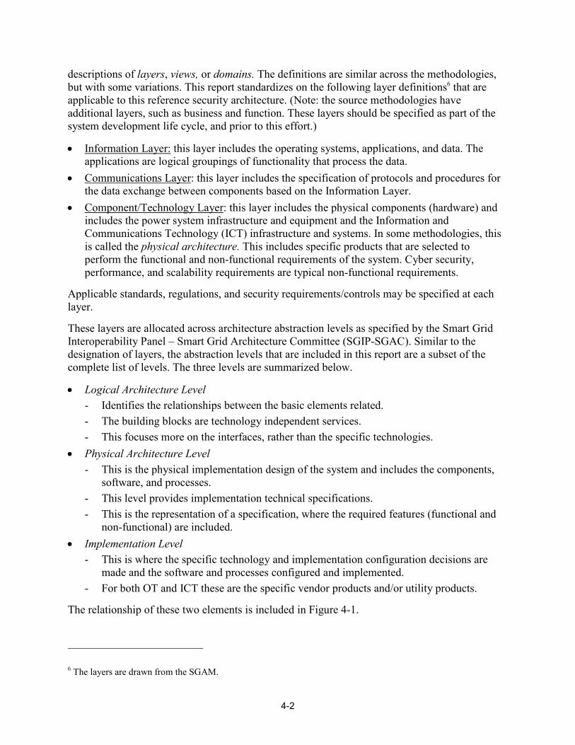
These layers are allocated across architecture abstraction levels as specified by the Smart Grid Interoperability Panel – Smart Grid Architecture Committee (SGIP-SGAC). Similar to the designation of layers, the abstraction levels that are included in this report are a subset of the complete list of levels. The three levels are summarized below.
• Logical Architecture Level - Identifies the relationships between the basic elements related. - The building blocks are technology independent services. - This focuses more on the interfaces, rather than the specific technologies.
• Physical Architecture Level - This is the physical implementation design of the system and includes the components,
software, and processes. - This level provides implementation technical specifications. - This is the representation of a specification, where the required features (functional and
non-functional) are included. • Implementation Level
- This is where the specific technology and implementation configuration decisions are made and the software and processes configured and implemented.
- For both OT and ICT these are the specific vendor products and/or utility products.
The relationship of these two elements is included in Figure 4-1.
6 The layers are drawn from the SGAM.
4-3
Figure 4-1 Architectural Abstraction Levels mapped onto SGAM Interoperability Layers
These layers and levels will be used in the reference security architecture described below.
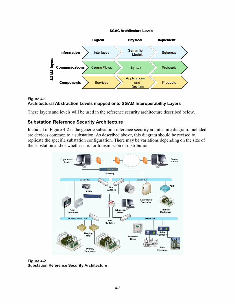
Substation Reference Security Architecture Included in Figure 4-2 is the generic substation reference security architecture diagram. Included are devices common to a substation. As described above, this diagram should be revised to replicate the specific substation configuration. There may be variations depending on the size of the substation and/or whether it is for transmission or distribution.
Figure 4-2 Substation Reference Security Architecture
4-4
The following steps specify how to develop the security architecture.
Step 1: Identify the Substation Device Classes To simplify the process, the substation IT and OT devices may be categorized in the following classes. Excluded are the specific power system devices including field equipment. These classes are used in analyzing the attack vectors and selecting the mitigation strategies.
1. Protection Relays: including relay controllers 2. Supervisory Control and Data Acquisition (SCADA): including RTUS, automation
controllers, and PLCs 3. Phasor Measurement Units (PMU) 4. Servers 5. Switches 6. Gateways/Routers/Firewalls 7. Merging Units: these devices aggregate sampled digital data and analog signals.
Step 2: Define the Overlays After the initial diagram is developed, overlays are applied. Overlays include the following:
• Communications Layer: physical medium, communication protocols, standards/regulations; • Information Layer: Operating Systems, Applications, Data, standards/regulations; • Attack vectors and access points, including vulnerabilities; • Response strategies including mitigation strategies, standards/regulations.
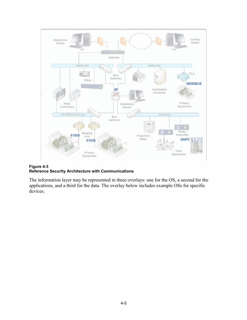
One way to illustrate the overlays is to use Visio. The overlay below includes example communication protocols.
4-5
Figure 4-3 Reference Security Architecture with Communications
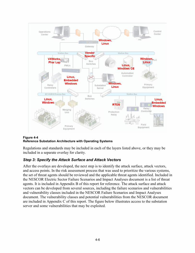
The information layer may be represented in three overlays: one for the OS, a second for the applications, and a third for the data. The overlay below includes example OSs for specific devices.
4-6
Figure 4-4 Reference Substation Architecture with Operating Systems
Regulations and standards may be included in each of the layers listed above, or they may be included in a separate overlay for clarity.
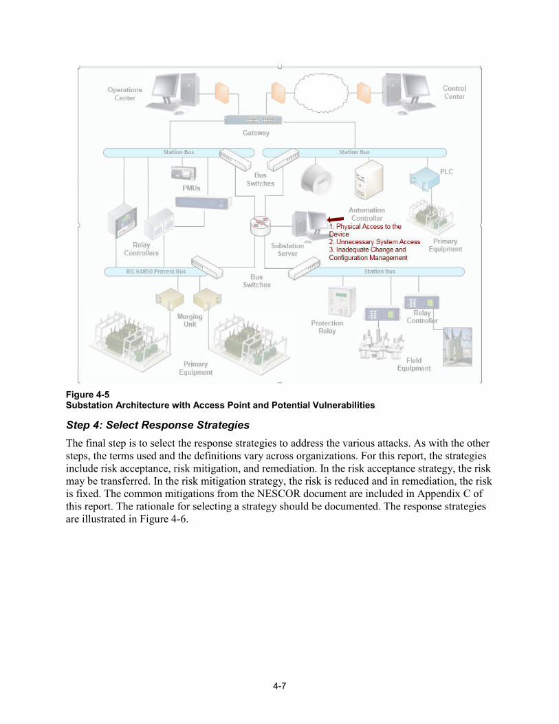
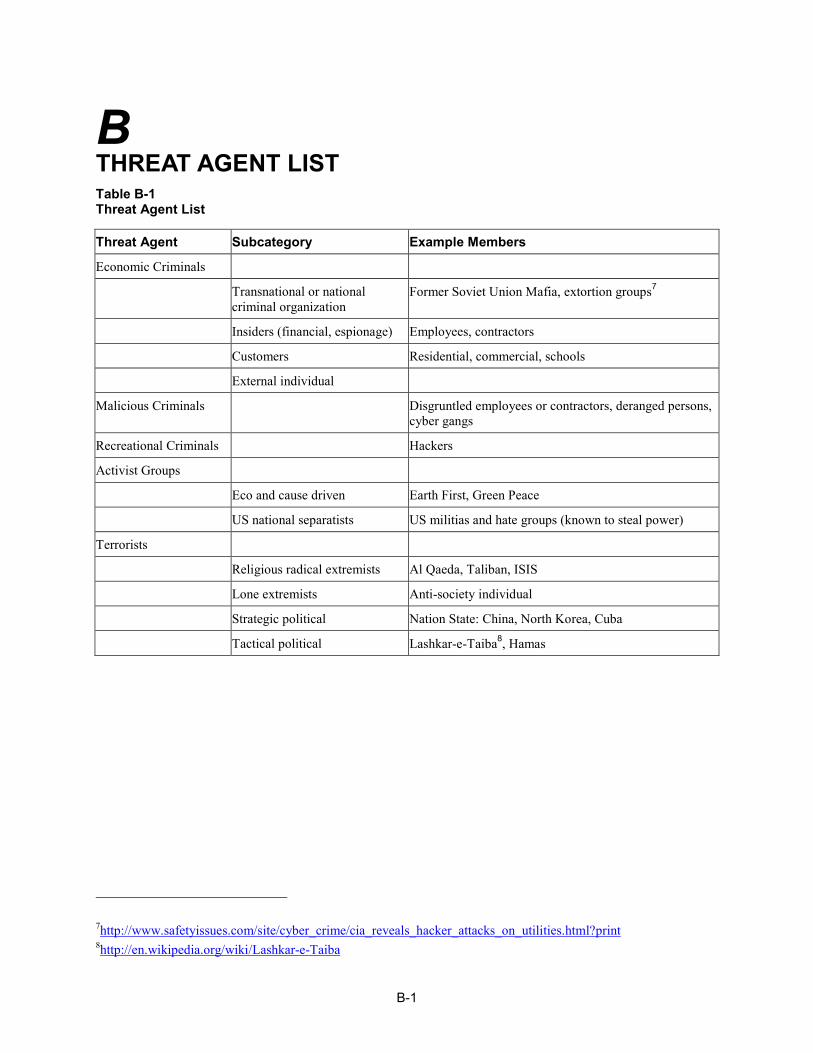
Step 3: Specify the Attack Surface and Attack Vectors After the overlays are developed, the next step is to identify the attack surface, attack vectors, and access points. In the risk assessment process that was used to prioritize the various systems, the set of threat agents should be reviewed and the applicable threat agents identified. Included in the NESCOR Electric Sector Failure Scenarios and Impact Analyses document is a list of threat agents. It is included in Appendix B of this report for reference. The attack surface and attack vectors can be developed from several sources, including the failure scenarios and vulnerabilities and vulnerability classes included in the NESCOR Failure Scenarios and Impact Analyses document. The vulnerability classes and potential vulnerabilities from the NESCOR document are included in Appendix C of this report. The figure below illustrates access to the substation server and some vulnerabilities that may be exploited.
4-7
Figure 4-5 Substation Architecture with Access Point and Potential Vulnerabilities
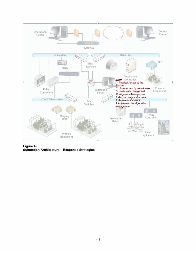
Step 4: Select Response Strategies The final step is to select the response strategies to address the various attacks. As with the other steps, the terms used and the definitions vary across organizations. For this report, the strategies include risk acceptance, risk mitigation, and remediation. In the risk acceptance strategy, the risk may be transferred. In the risk mitigation strategy, the risk is reduced and in remediation, the risk is fixed. The common mitigations from the NESCOR document are included in Appendix C of this report. The rationale for selecting a strategy should be documented. The response strategies are illustrated in Figure 4-6.
4-8
Figure 4-6 Substation Architecture – Response Strategies
5-1
5 NEXT STEPS A security architecture is one tool that utilities may use to define the current and target architectures including the attack surface and response strategies. In 2015, the focus is on a review of existing architecture methodologies and frameworks and how they can be used for security architectures. This document is the first version of the security architecture methodology and includes the basic approach and common terms and definitions. The contents of this document represent the core components of the methodology and will be expanded upon in the report produced next year (2016).
The results of this project will be coordinated with the EPRI security metrics, risk assessment, and ISOC projects. The goal is to leverage the output across the projects.
To ensure that the security architecture methodology is standardized across the electric sector, this report will be released publicly and feedback requested. In particular, comments will be required on the substation device categories and the overlay layers. The goal is to ensure that the methodology and associated terms and concepts are practical for utilities of all sizes and varying levels of sophistication in addressing cyber security. Future work will be coordinated with such organizations as NRECA, APPA, and EEI.
Future Research Topics In 2016, the application of the methodology to the substation will be expanded to identify additional components at the different layers and the associated attack vectors, vulnerabilities, and response strategies.
Some of the areas that will need future research to determine how they should be included in the security architecture are:
• Specific technologies such as cloud computing and virtualization • Insider threat • Technology standards including configuration recommendations • Application to other electric sector areas, such as control center.
Once the substation methodology is completed, the next step is to perform pilots at one or more utilities. Based on the pilots, changes will be made to the methodology. The final step is to develop tools, for members only, which may be used by the utilities as they develop their security architectures.

6-1
6 REFERENCES 1. Philippe Kruchten, Architectural Blueprints – The “4+1” View Mode of Software
Architecture, IEEE Software, November 1995, pp. 42-50. [scientific journal] 2. Antonio, Vallecillo, RM-ODP: The ISO Reference Model for Open Distributed Processing,
DINTEL Edition on Software Engineering. No. 3. pp. 69-99. March 2001. [scientific journal] 3. Mathias Uslar and Dominik Engel, Towards Generic Domain Reference Description: How to
learn from Smart Grid Interoperability, November 2015. [conference paper] 4. Mathias Uslar, Michael Spect, et al, Standardization in Smart Grids – Introduction to IT-
Related Methodologies, Architectures and Standards, Springer Heidelberg, 2012. [report] 5. M/490 Reference Architecture WG, Framework for Smart Grid Architecture Models, 2011.
[briefing] 6. SCE-CISCO-SGRA Team, Smart Grid Reference Architecture, Volume 1, Using Information
and Communication Services to Support a Smarter Grid, 2011. [report] 7. Pacific Northwest National Laboratory, The Emerging Interdependence of the Electric Power
Grid & Information and Communication Technology, August 2015. [report] 8. ISO/IEC/IEEE, Systems and software engineering – Architecture description, First edition,
2011-12-01, ISO/IEC/IEEE 42010, 2011. [standard] 9. SGIP-SGAC-ADWP, Architecture Frameworks, Models, Abstraction Levels, and Element
Classification – Removing Ambiguity and Providing Guidance for Interpretation and Use, September 2015. [briefing]
10. SGIP-SGAC-ADWP, Mapping Architectural Elements between SOA and ArchiMate 2.1 – Draft r0.5, 2015. [report]
11. A. Leonardi, K. Mathioudakis, A. Wiesmaler, and F. Zeiger, Towards the Smart Grid: Substation Automation Architecture and Technologies, Advances in Electrical Engineering, Volume 2014, 2014. [scientific journal]
12. National Institute of Standards and Technology, Framework for Improving Critical Infrastructure Cybersecurity Version 1.0, February 12, 2014 [report]
13. National Electric Sector Cybersecurity Organization Resource, Electric Sector Failure Scenarios and Impact Analyses, Version 2.0, June 2014. [report]
14. National Institution of Standards and Technology Interagency Report (NISTIR) 7628, Guidelines for Smart Grid Cyber Security, Rev. 1, June 2014. [report]

A-1
A ACRONYMS AND ABBREVIATIONS ADM Architecture Development Method
ADWP Architecture Development Working Party
ANSI American National Standards Institute
APPA American Public Power Association
CEN The European Committee for Standardisation
CENELEC The European Committee for Electrotechnical Standardization
DER Distributed Energy Resources
DOE Department of Energy
EEI Edison Electric Institute
EISA Energy Independence and Security Act
EPRI Electric Power Research Institute
ETSI The European Telecommunications Standards Institute
ICT Information and Communications Technology
IEC International Electrotechnical Commission
IEEE Institute of Electrical and Electronics Engineers
IOU Investor Owned Utility
ISO International Organization for Standardization
ISOC Integrated Security Operations Center
IT Information Technology
NESCOR National Electric Sector Cybersecurity Organization Resource
NIST National Institute of Standards and Technology
NISTIR NIST Interagency Report
NRECA National Rural Electric Cooperative Association
OSA Open Security Architecture
OT Operations Technology
A-2
SGAC Smart Grid Architecture Committee
SGAM Smart Grid Architecture Model
SGCC Smart Grid Cybersecurity Committee
SGIP Smart Grid Interoperability Panel
SP Special Publication
TC Technical Committee
TOGAF The Open Group Architecture Framework
UTC Utilities Telecom Council
B-1
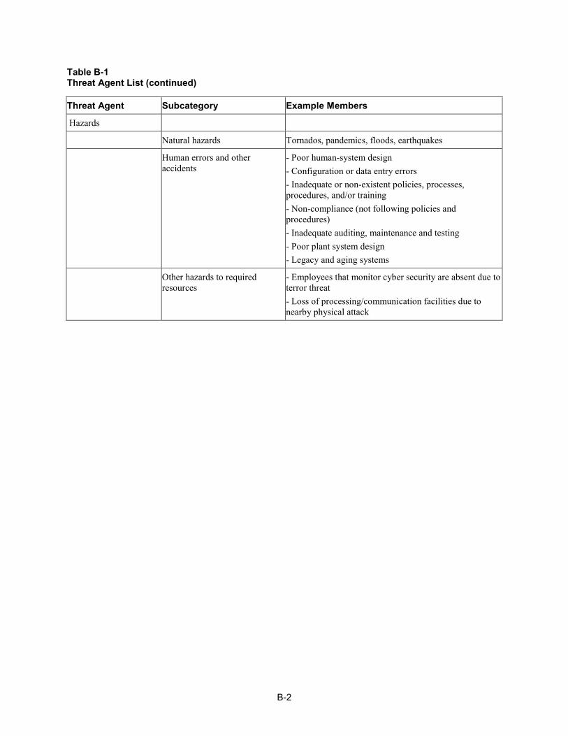
B THREAT AGENT LIST Table B-1 Threat Agent List
Threat Agent Subcategory Example Members
Economic Criminals
Transnational or national criminal organization
Former Soviet Union Mafia, extortion groups7
Insiders (financial, espionage) Employees, contractors
Customers Residential, commercial, schools
External individual
Malicious Criminals Disgruntled employees or contractors, deranged persons, cyber gangs
Recreational Criminals Hackers
Activist Groups
Eco and cause driven Earth First, Green Peace
US national separatists US militias and hate groups (known to steal power)
Terrorists
Religious radical extremists Al Qaeda, Taliban, ISIS
Lone extremists Anti-society individual
Strategic political Nation State: China, North Korea, Cuba
Tactical political Lashkar-e-Taiba8, Hamas
7http://www.safetyissues.com/site/cyber_crime/cia_reveals_hacker_attacks_on_utilities.html?print 8http://en.wikipedia.org/wiki/Lashkar-e-Taiba
B-2
Table B-1 Threat Agent List (continued)
Threat Agent Subcategory Example Members
Hazards
Natural hazards Tornados, pandemics, floods, earthquakes
Human errors and other accidents
- Poor human-system design - Configuration or data entry errors - Inadequate or non-existent policies, processes, procedures, and/or training - Non-compliance (not following policies and procedures) - Inadequate auditing, maintenance and testing - Poor plant system design - Legacy and aging systems
Other hazards to required resources
- Employees that monitor cyber security are absent due to terror threat - Loss of processing/communication facilities due to nearby physical attack
C-1
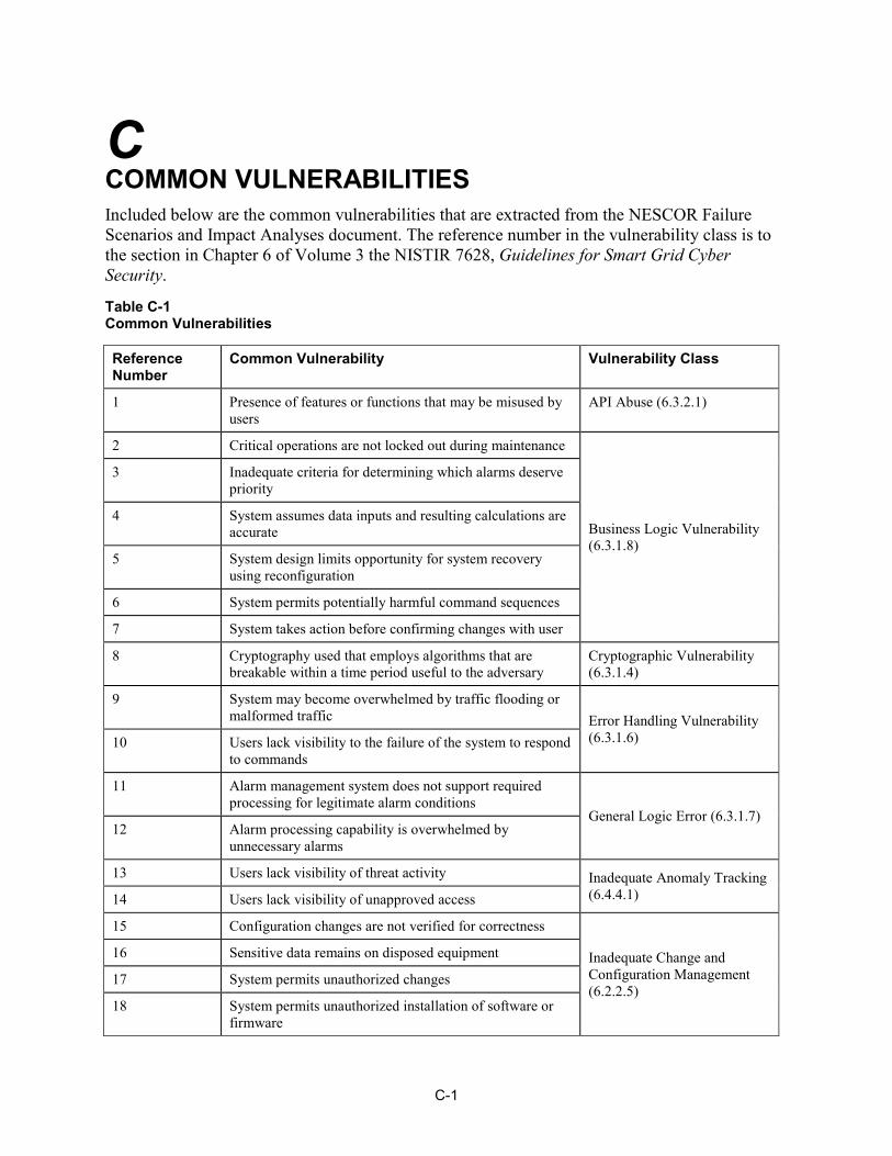
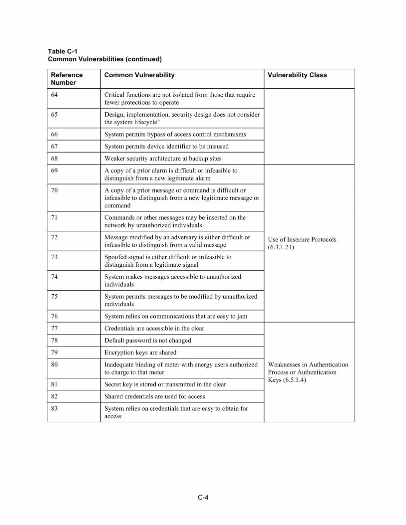
C COMMON VULNERABILITIES Included below are the common vulnerabilities that are extracted from the NESCOR Failure Scenarios and Impact Analyses document. The reference number in the vulnerability class is to the section in Chapter 6 of Volume 3 the NISTIR 7628, Guidelines for Smart Grid Cyber Security.
Table C-1 Common Vulnerabilities
Reference Number
Common Vulnerability Vulnerability Class
1 Presence of features or functions that may be misused by users
API Abuse (6.3.2.1)
2 Critical operations are not locked out during maintenance
Business Logic Vulnerability (6.3.1.8)
3 Inadequate criteria for determining which alarms deserve priority
4 System assumes data inputs and resulting calculations are accurate
5 System design limits opportunity for system recovery using reconfiguration
6 System permits potentially harmful command sequences
7 System takes action before confirming changes with user
8 Cryptography used that employs algorithms that are breakable within a time period useful to the adversary
Cryptographic Vulnerability (6.3.1.4)
9 System may become overwhelmed by traffic flooding or malformed traffic Error Handling Vulnerability
(6.3.1.6) 10 Users lack visibility to the failure of the system to respond to commands
11 Alarm management system does not support required processing for legitimate alarm conditions
General Logic Error (6.3.1.7) 12 Alarm processing capability is overwhelmed by
unnecessary alarms
13 Users lack visibility of threat activity Inadequate Anomaly Tracking (6.4.4.1) 14 Users lack visibility of unapproved access
15 Configuration changes are not verified for correctness
Inadequate Change and Configuration Management (6.2.2.5)
16 Sensitive data remains on disposed equipment
17 System permits unauthorized changes
18 System permits unauthorized installation of software or firmware
C-2
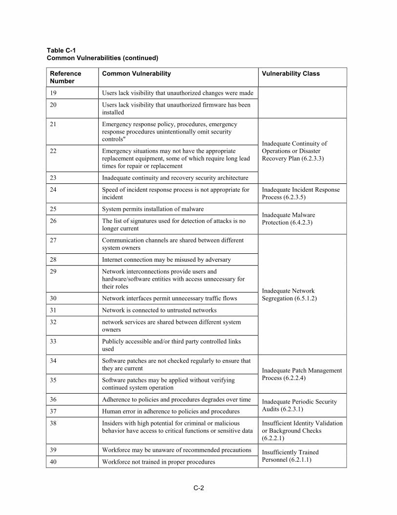
Table C-1 Common Vulnerabilities (continued)
Reference Number
Common Vulnerability Vulnerability Class
19 Users lack visibility that unauthorized changes were made
20 Users lack visibility that unauthorized firmware has been installed
21 Emergency response policy, procedures, emergency response procedures unintentionally omit security controls"
Inadequate Continuity of Operations or Disaster Recovery Plan (6.2.3.3)
22 Emergency situations may not have the appropriate replacement equipment, some of which require long lead times for repair or replacement
23 Inadequate continuity and recovery security architecture
24 Speed of incident response process is not appropriate for incident
Inadequate Incident Response Process (6.2.3.5)
25 System permits installation of malware Inadequate Malware Protection (6.4.2.3) 26 The list of signatures used for detection of attacks is no
longer current
27 Communication channels are shared between different system owners
Inadequate Network Segregation (6.5.1.2)
28 Internet connection may be misused by adversary
29 Network interconnections provide users and hardware/software entities with access unnecessary for their roles
30 Network interfaces permit unnecessary traffic flows
31 Network is connected to untrusted networks
32 network services are shared between different system owners
33 Publicly accessible and/or third party controlled links used
34 Software patches are not checked regularly to ensure that they are current Inadequate Patch Management
Process (6.2.2.4) 35 Software patches may be applied without verifying continued system operation
36 Adherence to policies and procedures degrades over time Inadequate Periodic Security Audits (6.2.3.1) 37 Human error in adherence to policies and procedures
38 Insiders with high potential for criminal or malicious behavior have access to critical functions or sensitive data
Insufficient Identity Validation or Background Checks (6.2.2.1)
39 Workforce may be unaware of recommended precautions Insufficiently Trained Personnel (6.2.1.1) 40 Workforce not trained in proper procedures
C-3
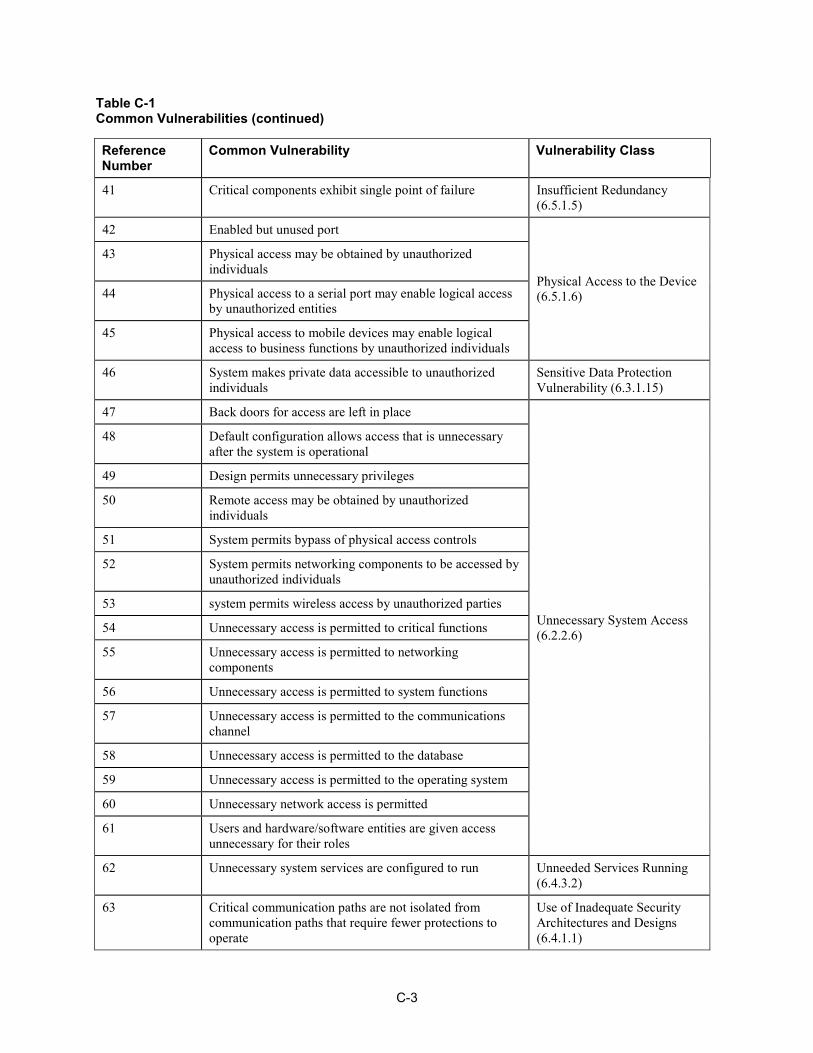
Table C-1 Common Vulnerabilities (continued)
Reference Number
Common Vulnerability Vulnerability Class
41 Critical components exhibit single point of failure Insufficient Redundancy (6.5.1.5)
42 Enabled but unused port
Physical Access to the Device (6.5.1.6)
43 Physical access may be obtained by unauthorized individuals
44 Physical access to a serial port may enable logical access by unauthorized entities
45 Physical access to mobile devices may enable logical access to business functions by unauthorized individuals
46 System makes private data accessible to unauthorized individuals
Sensitive Data Protection Vulnerability (6.3.1.15)
47 Back doors for access are left in place
Unnecessary System Access (6.2.2.6)
48 Default configuration allows access that is unnecessary after the system is operational
49 Design permits unnecessary privileges
50 Remote access may be obtained by unauthorized individuals
51 System permits bypass of physical access controls
52 System permits networking components to be accessed by unauthorized individuals
53 system permits wireless access by unauthorized parties
54 Unnecessary access is permitted to critical functions
55 Unnecessary access is permitted to networking components
56 Unnecessary access is permitted to system functions
57 Unnecessary access is permitted to the communications channel
58 Unnecessary access is permitted to the database
59 Unnecessary access is permitted to the operating system
60 Unnecessary network access is permitted
61 Users and hardware/software entities are given access unnecessary for their roles
62 Unnecessary system services are configured to run Unneeded Services Running (6.4.3.2)
63 Critical communication paths are not isolated from communication paths that require fewer protections to operate
Use of Inadequate Security Architectures and Designs (6.4.1.1)
C-4
Table C-1 Common Vulnerabilities (continued)
Reference Number
Common Vulnerability Vulnerability Class
64 Critical functions are not isolated from those that require fewer protections to operate
65 Design, implementation, security design does not consider the system lifecycle"
66 System permits bypass of access control mechanisms
67 System permits device identifier to be misused
68 Weaker security architecture at backup sites
69 A copy of a prior alarm is difficult or infeasible to distinguish from a new legitimate alarm
Use of Insecure Protocols (6.3.1.21)
70 A copy of a prior message or command is difficult or infeasible to distinguish from a new legitimate message or command
71 Commands or other messages may be inserted on the network by unauthorized individuals
72 Message modified by an adversary is either difficult or infeasible to distinguish from a valid message
73 Spoofed signal is either difficult or infeasible to distinguish from a legitimate signal
74 System makes messages accessible to unauthorized individuals
75 System permits messages to be modified by unauthorized individuals
76 System relies on communications that are easy to jam
77 Credentials are accessible in the clear
Weaknesses in Authentication Process or Authentication Keys (6.5.1.4)
78 Default password is not changed
79 Encryption keys are shared
80 Inadequate binding of meter with energy users authorized to charge to that meter
81 Secret key is stored or transmitted in the clear
82 Shared credentials are used for access
83 System relies on credentials that are easy to obtain for access
D-1
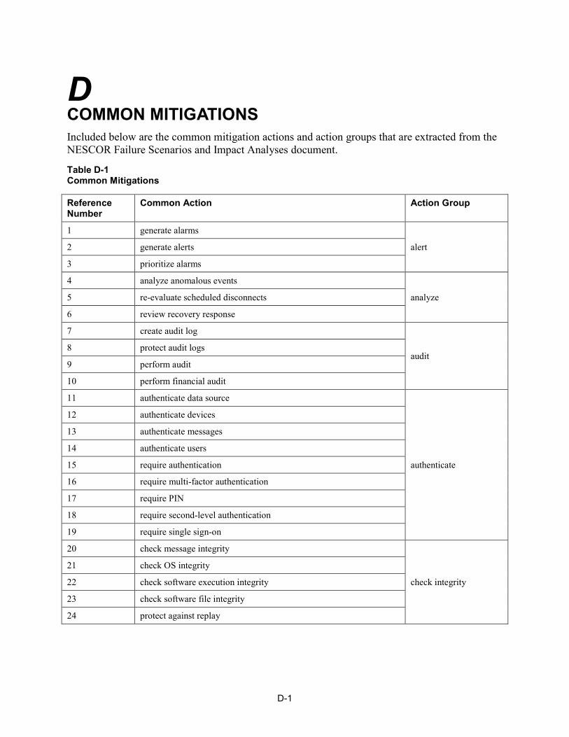
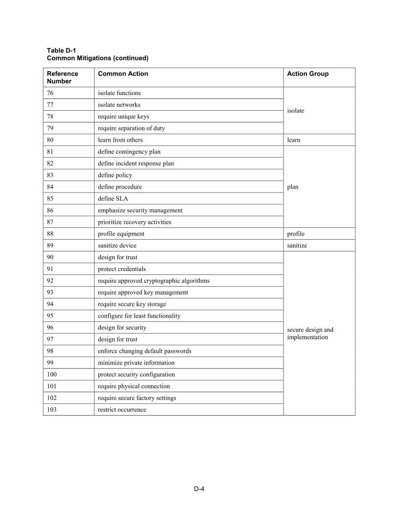
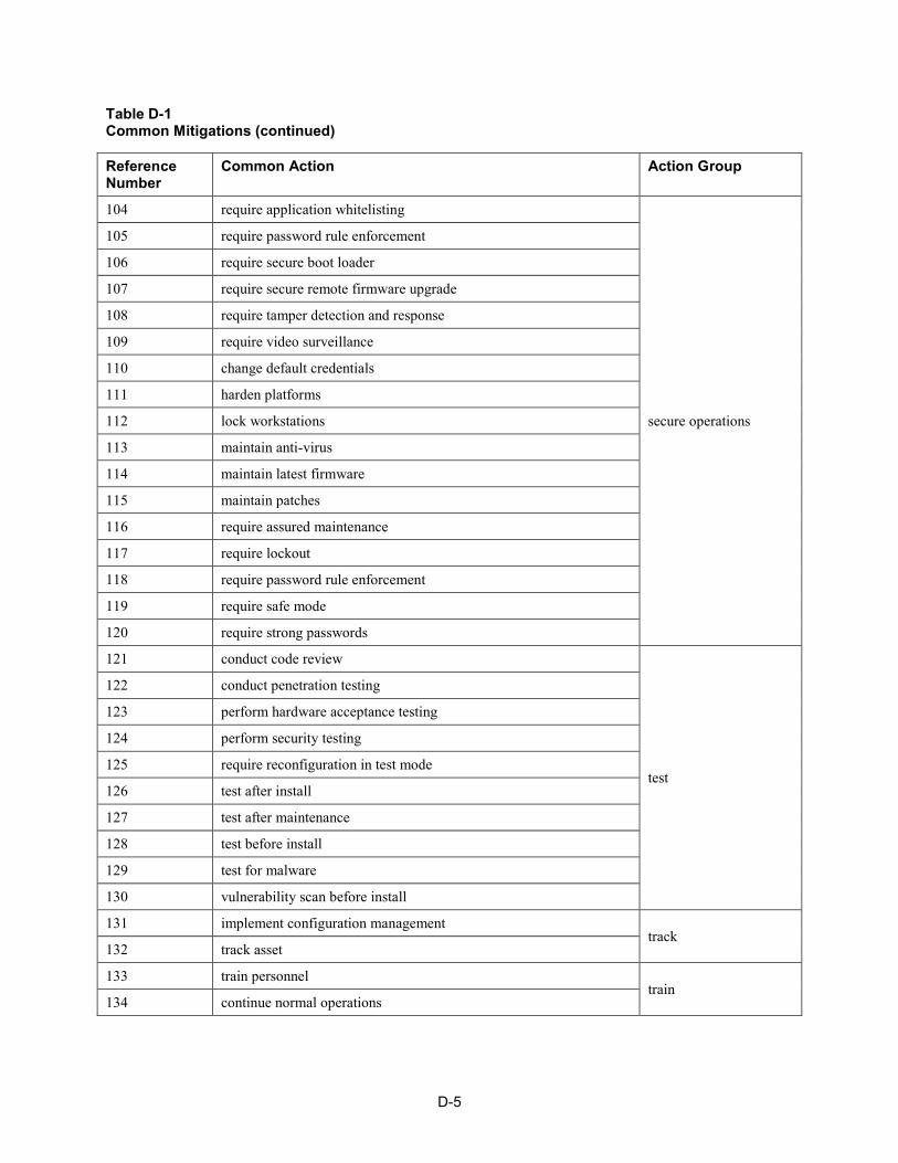
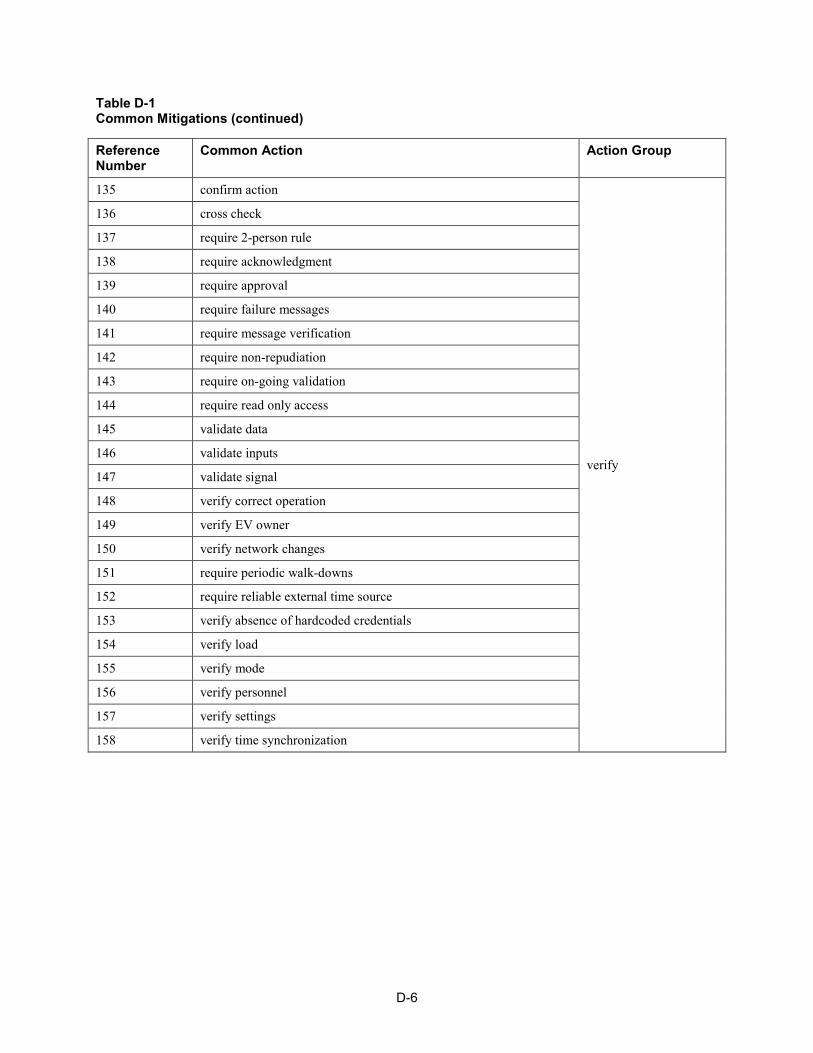
D COMMON MITIGATIONS Included below are the common mitigation actions and action groups that are extracted from the NESCOR Failure Scenarios and Impact Analyses document.
Table D-1 Common Mitigations
Reference Number
Common Action Action Group
1 generate alarms
alert 2 generate alerts
3 prioritize alarms
4 analyze anomalous events
analyze 5 re-evaluate scheduled disconnects
6 review recovery response
7 create audit log
audit 8 protect audit logs
9 perform audit
10 perform financial audit
11 authenticate data source
authenticate
12 authenticate devices
13 authenticate messages
14 authenticate users
15 require authentication
16 require multi-factor authentication
17 require PIN
18 require second-level authentication
19 require single sign-on
20 check message integrity
check integrity
21 check OS integrity
22 check software execution integrity
23 check software file integrity
24 protect against replay
D-2
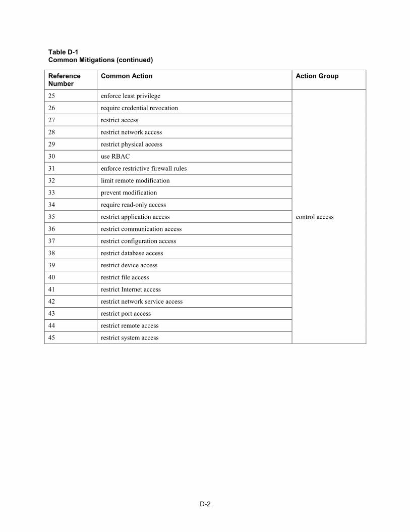
Table D-1 Common Mitigations (continued)
Reference Number
Common Action Action Group
25 enforce least privilege
control access
26 require credential revocation
27 restrict access
28 restrict network access
29 restrict physical access
30 use RBAC
31 enforce restrictive firewall rules
32 limit remote modification
33 prevent modification
34 require read-only access
35 restrict application access
36 restrict communication access
37 restrict configuration access
38 restrict database access
39 restrict device access
40 restrict file access
41 restrict Internet access
42 restrict network service access
43 restrict port access
44 restrict remote access
45 restrict system access
D-3
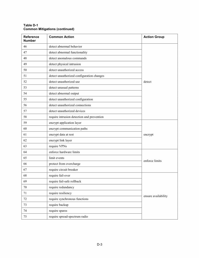
Table D-1 Common Mitigations (continued)
Reference Number
Common Action Action Group
46 detect abnormal behavior
detect
47 detect abnormal functionality
48 detect anomalous commands
49 detect physical intrusion
50 detect unauthorized access
51 detect unauthorized configuration changes
52 detect unauthorized use
53 detect unusual patterns
54 detect abnormal output
55 detect unauthorized configuration
56 detect unauthorized connections
57 detect unauthorized devices
58 require intrusion detection and prevention
59 encrypt application layer
encrypt
60 encrypt communication paths
61 encrypt data at rest
62 encrypt link layer
63 require VPNs
64 enforce hardware limits
enforce limits 65 limit events
66 protect from overcharge
67 require circuit breaker
68 require fail-over
ensure availability
69 require fail-safe rollback
70 require redundancy
71 require resiliency
72 require synchronous functions
73 require backup
74 require spares
75 require spread-spectrum radio
D-4
Table D-1 Common Mitigations (continued)
Reference Number
Common Action Action Group
76 isolate functions
isolate 77 isolate networks
78 require unique keys
79 require separation of duty
80 learn from others learn
81 define contingency plan
plan
82 define incident response plan
83 define policy
84 define procedure
85 define SLA
86 emphasize security management
87 prioritize recovery activities
88 profile equipment profile
89 sanitize device sanitize
90 design for trust
secure design and implementation
91 protect credentials
92 require approved cryptographic algorithms
93 require approved key management
94 require secure key storage
95 configure for least functionality
96 design for security
97 design for trust
98 enforce changing default passwords
99 minimize private information
100 protect security configuration
101 require physical connection
102 require secure factory settings
103 restrict occurrence
D-5
Table D-1 Common Mitigations (continued)
Reference Number
Common Action Action Group
104 require application whitelisting
secure operations
105 require password rule enforcement
106 require secure boot loader
107 require secure remote firmware upgrade
108 require tamper detection and response
109 require video surveillance
110 change default credentials
111 harden platforms
112 lock workstations
113 maintain anti-virus
114 maintain latest firmware
115 maintain patches
116 require assured maintenance
117 require lockout
118 require password rule enforcement
119 require safe mode
120 require strong passwords
121 conduct code review
test
122 conduct penetration testing
123 perform hardware acceptance testing
124 perform security testing
125 require reconfiguration in test mode
126 test after install
127 test after maintenance
128 test before install
129 test for malware
130 vulnerability scan before install
131 implement configuration management track
132 track asset
133 train personnel train
134 continue normal operations
D-6
Table D-1 Common Mitigations (continued)
Reference Number
Common Action Action Group
135 confirm action
verify
136 cross check
137 require 2-person rule
138 require acknowledgment
139 require approval
140 require failure messages
141 require message verification
142 require non-repudiation
143 require on-going validation
144 require read only access
145 validate data
146 validate inputs
147 validate signal
148 verify correct operation
149 verify EV owner
150 verify network changes
151 require periodic walk-downs
152 require reliable external time source
153 verify absence of hardcoded credentials
154 verify load
155 verify mode
156 verify personnel
157 verify settings
158 verify time synchronization

Electric Power Research Institute 3420 Hillview Avenue, Palo Alto, California 94304-1338 • PO Box 10412, Palo Alto, California 94303-0813 • USA
800.313.3774 • 650.855.2121 • [email protected] • www.epri.com
The Electric Power Research Institute, Inc. (EPRI, www.epri.com) conducts research and development relating to the generation, delivery and use of electricity for the benefit of the public. An independent, nonprofit organization, EPRI brings together its scientists and engineers as well as experts from academia and industry to help address challenges in electricity, including reliability, efficiency, affordability, health, safety and the environment. EPRI also provides technology, policy and economic analyses to drive long-range research and development planning, and supports research in emerging technologies. EPRI’s members represent approximately 90 percent of the electricity generated and delivered in the United States, and international participation extends to more than 30 countries. EPRI’s principal offices and laboratories are located in Palo Alto, Calif.; Charlotte, N.C.; Knoxville, Tenn.; and Lenox, Mass.
Together…Shaping the Future of Electricity
© 2015 Electric Power Research Institute (EPRI), Inc. All rights reserved. Electric Power Research Institute, EPRI, and TOGETHER…SHAPING THE FUTURE OF ELECTRICITY are registered service marks of the Electric Power Research Institute, Inc.
3002005942