CX SERIES - Buckhorn Pumps, Inc Pumps/Manuals/CX Series.pdfReciprocating pumps of both the plunger...
12
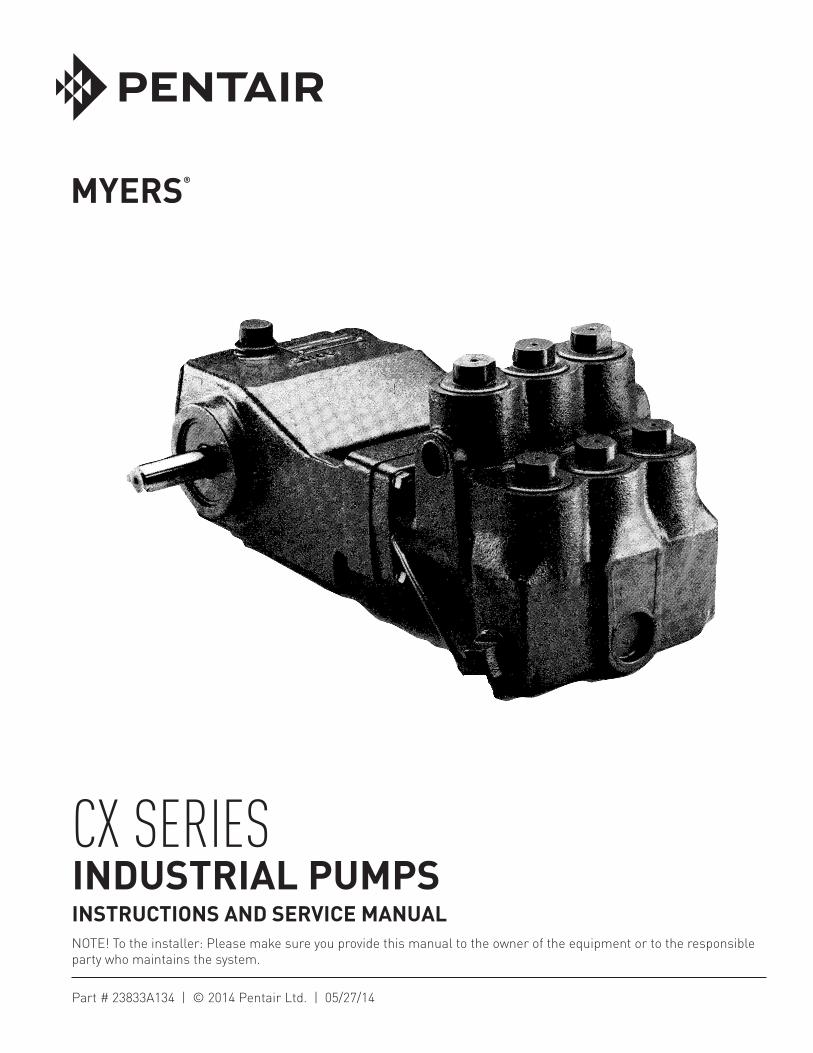
NOTE! To the installer: Please make sure you provide this manual to the owner of the equipment or to the responsible party who maintains the system. CX SERIES INDUSTRIAL PUMPS INSTRUCTIONS AND SERVICE MANUAL Part # 23833A134 | © 2014 Pentair Ltd. | 05/27/14
Transcript of CX SERIES - Buckhorn Pumps, Inc Pumps/Manuals/CX Series.pdfReciprocating pumps of both the plunger...
NOTE! To the installer: Please make sure you provide this manual to the owner of the equip ment or to the responsible party who maintains the system.
CX SERIESINDUSTRIAL PUMPSINSTRUCTIONS AND SERVICE MANUAL
Part # 23833A134 | © 2014 Pentair Ltd. | 05/27/14
23833A134 05/27/12 2
Reciprocating pumps of both the plunger and piston type are positive displacement in principle. Due to positive displacement characteristics, problems may arise through improper installation or application. When new or unusual installations are planned, or the material to be pumped is a liquid other than cold water, the customer should consult the “Myers® Reciprocating Pump Manual” or factory for additional information.
CAUTION
Positive displacement pumps must have a proper size and operable type of pressure regulating valve or pressure relief valve piped into the discharge line. This is mandatory to prevent damage to pump and piping or possible injury to personnel. Do not install any valves or shutoff devices in the bypass line from pressure regulator to tank or supply.
CAUTION
All pumps should be installed level. For mobile applications the maximum angle of intermittent operation should be no more than 5 degrees in any one direction.
CALIFORNIA PROPOSITION 65 WARNING:
This product and related accessories contain chemicals known to the State of California to cause cancer, birth defects or other reproductive harm.
INSTALLATION (Customer mounted pump)
If possible, install suction piping one pipe size larger than suction tapping in pump. Reduce piping size at pump with a reducer coupling as shown on installation drawings. A suction surge arrester will assure smoother operation. When level of liquid supply is below that of the pump either the bottom opening or both side openings must be connected to the supply. Keep suction piping as short and simple as possible with a minimum of lift. Avoid any high points in suction line.
Suction piping must not have any air leaks. Check suction piping assembly for leaks by using 20-80 psi air pressure and soap bubbles or submerging assembly under water.
Use suction strainer and screen of adequate size to avoid restriction of pump suction. Strainer mesh should be sufficiently small to prevent passage of trash which may lodge under pump valves. Keep screen clean with a regular maintenance schedule to avoid starving of pump suction. A starved suction condition is usually indicated by excessive pump shock and noise. Many pump problems and most plunger or packing problems are directly traceable to a starved suction condition.
When pumping liquids that are heated, reduce pump speed to avoid suction problems. Consult “Myers Reciprocating Pump Manual” or factory for temperature and speed limitations.
Make sure that drive is adequate for horsepower required and that drive is properly aligned and tensioned. With belt drives, pulleys on both motor and pump should be located as closely as possible to bearing to reduce bearing and shaft bending loads.
CAUTIon: Be sure that pump belts and pulleys are properly protected by guards according to industrial code within state of application.
Make sure that all bolts, nuts, set screws and keys are properly tightened. Be sure that the discharge line is properly protected by means of a pressure regulating valve and a discharge surge arrester of proper size, capacity and pressure rating. The discharge line should be of comparable size to discharge tapping in pump.
nozzle capacity or demand should not exceed 90% of pump capacity for satisfactory regulating valve operation. nozzling in excess of this capacity may cause unstable pressure regulator operation. It is also preferred to nozzle in excess of 50% of pump capacity to reduce rate of erosion or wear on regulating valve and seat.
When lower system demands (than rated pump capacity) are required in an installation, the pump speed should be reduced by changing drive ratios. This will reflect savings in power consumption, reduce regulating valve wear and extend pump life.
Where line shock or water hammer is encountered a second surge arrester should be installed in the discharge line adjacent to spray gun or nozzles. Under some conditions it may also be desirable to isolate pump from piping with suitable high pressure hose. This will eliminate transmission of line vibration to the pump, with a resulting possible failure of piping, pipe threads, and/or pump casting.
never pipe the bypass from a pressure regulating valve back into the pump suction. When discharge line is shut off, the complete bypass is circulated back into pump suction with a resulting rapid temperature rise which will destroy the plunger seal/piston packing.
It is permissible to pipe the bypass from an unloader valve into the suction because the pump pressure is unloaded when discharge is shut off.
23833A134 05/27/143
STARTING PUmP
Read all instructions carefully. Fill pump crankcase with recommended oil to the level mark on oil saber. oil recommendations are covered in the lubrication section of pump instructions. Replace all drain plugs in pump and piping. Inspect tank to be sure that no foreign material is in the tank or suction line. Fill tank at least half full or connect suction to water supply. open valve (if present) in suction line. If pumping from a pit, make sure that the suction line is completely submerged. Make sure all valves, including spray gun or nozzles, are open in discharge line. Spray gun may be anchored to discharge back into tank. Completely back off pressure adjusting screw on pressure regulating valve.
CAUTIon: When pumping from a pit or under a suction lift condition, if pump does not prime in a short period, fill the discharge side of the fluid end with water to seal discharge valves. If pump still does not prime, remove suction hose and fill pump with water. Dry operation will cause heating and wear on plunger seal. Be sure that an operating pressure gauge is located on the discharge line.
STARTING The UNIT
After starting, close discharge valve or spray gun slowly while watching pressure gauge to make sure relief valve or unloader is operating properly. Adjust relief valve to desired pressure. See regulator instructions. Cycle nozzles, or gun, on and off to be sure that pressure adjustment and regulator operation is satisfactory.
LUbRICATION ANd SeRvICe
LUbRICATION
Pump- Crankcase must be filled with 2 to 2-1/2 pints of S.A.E. 30 oil unless ambient temperature exceeds 90°F, when S.A.E. 40 should be used. Use only quality oils with API designation MS, SC, or SD; maintain level at mark on dipstick. Foaming and yellow discoloration of oil is an indication of water; oil should be changed immediately to preclude possible damage to power and components.
noTE - Drain oil from crankcase after first 30 hours of operation. It is best to always drain the oil when it is still hot. Refill with new oil as mentioned above. Run pump at full speed under no pressure for 2 or 3 minutes before returning to operation. Therefore change oil every 300 hours or immediately if water droplets are found on dipstick. Check oil level regularly and add oil as needed.
Avoid freezing by draining all water from pump and system in cold weather. This can be done by breaking suction connections, removing pipe plug from front
face of pump and turning crankshaft over 4 or 5 times, or the fluid end can be removed to completely drain cylinders and fluid end.
SeRvICe
Disconnect electrical leads to motor, or remove spark plug leads on engine.
PLUNGeR SeAL SeRvICe - CXP SeRIeS
Removal: Remove eight nuts holding fluid end to power end and pull straight forward. Use care with ceramic plunger pumps. Unscrew plunger from top opening and pull plunger out. Use screwdriver to pry the seal housing out. May take use of the crosshead to push seal housing out by inserting a block between crosshead and seal housing.
When replacing the plunger seal, clean all plungers, replace and lubricate o-rings. Ceramic plungers should be cleaned by soaking in muriatic acid to remove all build-up of packing material. Caution! Avoid direct contact with muriatic acid. Wear protective gloves and eye protection. If exposed, flush exposed area with water. Consult a physician for treatment of muriatic acid burns. Clean bore and lubricate o-rings and plunger seal with a quality waterproof grease before replacing seal housing and plunger. The plunger should be inserted into crosshead. Hand turn all the way until it stops. Use wrench to finish. Torque to 45 ft/lbs. When the seal housing is seated properly, the plunger fastened to the crosshead and with all internal parts in place in fluid end, the fluid end can be replaced. Be sure to install flange gasket between fluid end and power end when reassembling.
Insert all nuts and lock washers in place and pull fluid end down tight. Do not cock fluid end while tightening, pull down evenly by alternately tightening to final torque 25-30 ft/lbs.
CyLINdeR & PACkING SeRvICe-CX10-20 SeRIeS
Removal: Remove eight cap screws holding fluid end to power end, and pull straight forward. Use care with ceramic liner pumps. Do not cock water end or drop liner. Valve seat valve spacer and spring should remain in fluid end. Loosen stem and piston assembly can be removed with a socket wrench through cylinder opening. If cylinders have corroded in place, they may be removed. Grease the o.D. when replacing.
When replacing packing, clean all piston parts, replace and lubricate o-rings. Ceramic cylinders should be cleaned by soaking in muriatic acid to remove all build-up of packing material. Caution! Avoid direct contact with muriatic acid. Wear
23833A134 05/27/12 4
protective gloves and eye protection. If exposed, flush exposed area with water. Consult a physician for treatment of muriatic acid burns. Clean bore and lubricate o-rings and cylinder with a quality waterproof grease before replacing cylinder and piston assembly. The piston assembly should be inserted into the opening. Care should be used to assure proper seating of the cylinder into the machined opening at the rear of the bore. When the cylinder is seated properly, and the piston assembly adjusted and locked in place, with all internal parts in place in fluid end, the fluid end can be replaced. Care should be taken in reassembly so that the large end of suction spring seats against cylinder and not between the cylinder and spacer. Be sure to install a nylon gasket between the cylinder and spacer when reassembling.
vALve SeRvICe-CXP SeRIeS
Remove the stainless steel shoulder screw which serves as a valve guide and spring retainer. The shoulder screw can be removed with a socket. Remove shoulder screw, spring retainer, spring and valve from the pump fluid end.
Assemble stud, retainer and three screws and insert screw heads through holes in valve seat. Rotate retainer to the right until heads catch and secure in place by screwing down stud firmly by hand. Place plate over stud and screw on nut. Torque slowly with wrench until seat breaks loose.
Both valve seats are identical and can be serviced the same way. Valve seats are usually distorted and cannot be reused unless the face is reground to flat conditions.
vALve SeRvICe-CX10-20 SeRIeS
To remove discharge valve or spring, remove water end and pull valve seat with a 3/4-16 UnF threaded rod or cap screw.
Suction valves will show a wear pattern on seating side but need not be replaced unless cranked or erosion is present on seating face. To replace valve seat, first clean both bores with sandpaper or emery cloth to remove all corrosion. Replace discharge valve and spring. o-rings on valve seat should be replaced and lubricated. Insert valve seat into bore, if resistance is met as o-rings enter bores, place a flat piece of wood on seat and tap into place with hammer.
SeRvICING CRANkCASe PARTS
To remove the crankshaft, the plungers or pistons and fluid end or cylinders must first be removed. Drain oil from crankcase and remove rear cover. Remove
retainer ring from bearing bore. The connecting link caps should be taken off and the free links pushed toward the water end as far as possible. Before removal, be sure to note the markings on the connecting links and caps. These parts are not interchangeable and must be reassembled in their original positions. The crankshaft bearings and bearing cap can now be removed by tapping with a hammer against a block of wood on one end of the crankshaft. The crankshaft should be supported so that as the bearings leave the bores the crank does not drop and damage a crank pin. Do not remove bearing from crankshaft unless replacement is necessary. After removing crankshaft, the links and crosshead can be pulled out the crankcase opening.
SeRvICING CONNeCTING LINkS
The connecting rod link is furnished with replaceable split sleeve bearing inserts at the crank throw and a steel backed bushing at the crosshead end. When new replacement links are obtained, these bushings are reamed to the proper size for immediate installation. If the bushing only is removed from an old link, it may be necessary to ream the replaced bushing to the proper inside diameter after it is pressed into the link. When placing the bushing in the link be sure that the oil holes in the bushing and link will be in line after the bushing is pressed into position.
The connecting links should be checked for bearing wear only if the pump shows signs, which might be due to a failing link, or during a general overhaul.
Unnecessary inspections may upset smooth operation and ultimately cause failure. If it becomes necessary to replace a link or crosshead, this can be done by driving out the link pin. When replacing the pin an arbor press should be used and care should be taken so that the link is not bent. As the pin is pressed in, occasionally the two sides of the crosshead will give enough to grip the link so that it will not operate freely. If this occurs, rotate the link and crosshead 180 degrees and tap the pin sharply in the opposite direction.
Always be sure that the proper side of the link is placed upward when attaching it to the crankshaft. The upper side contains three oil holes. These oil holes must be up to allow proper oil feeding.
It is never practical to attempt to re-fit connecting links to the crankshaft by filing or grinding the face of the link cap where it contacts the link. Torque for link bolts not to exceed 65-75 inch/lbs or 6 ft/lbs. Under normal conditions a crosshead will not wear, nor will the bore of the crankcase wear to the extent that oversize crossheads will be required. If extreme wear does occur, it will be due to severe damage from the lack of oil or a fairly large metal object scoring
23833A134 05/27/145
the crosshead bore. A clearance of .002" to .004" is standard for the crosshead. The parts can wear until considerably more clearance than this exists before harmful operation will occur.
ReCONdITIONING CRANkShAFTS
When crank pins are slightly damaged, they can sometimes be reconditioned for further use. This can be done with emery cloth and polishing until all ridges are completely removed. The final polishing operation should be performed by using a very fine emery cloth. This procedure can only be followed where the amount of sanding does not reduce the normal diameter of the crank pin.
Worn or corroded crank pins can be ground and polished down to .030” under the size when the cranks were new. The undersize connecting links are made especially for turned down crankshafts.
If the surface is badly damaged, the crankshaft can often be salvaged by “metallizing” the crank pins, regrinding and polishing to the original diameter.
RePLACING CROSSheAd SeALS
With the crankshaft and crossheads removed, the worn seals can be pried out. When installing new seals be sure to place them with the lip facing the power end and the metal face toward the water end. After cleaning the cavity and wiping with oil, the seal can be pressed into place with an arbor press or by tapping lightly with a hammer against a block of wood. When returning crossheads through new seals care should be taken not to turn back or damage the lip of the seal. An assembly thimble can be very helpful in this operation.
After replacing the crossheads and links, they should be pushed all the way forward; then the crankshaft can be replaced just as it was removed. All link caps should be tightened in place and free operation of the crank assured before replacing bearing cap and retainer ring. When replacing bearing cap, an assembly thimble is helpful. The thimble should be machined from high carbon steel and polished on the exterior to reduce possibility of seal lip damage. Clean and lubricate all seals and o-rings before replacing.
23833A134 05/27/12 6
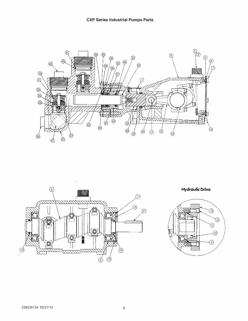
CXP Series Industrial Pumps Parts
8
10
9 12
10
21 13
23
12
22
9
13
11
50
47 2527
4234
4344
18
2019
24 1516
14
7
65
32
4
1
39
33
45
37
35
36
38
49
484641
4032
29
31
30
26
28
17
23833A134 05/27/147
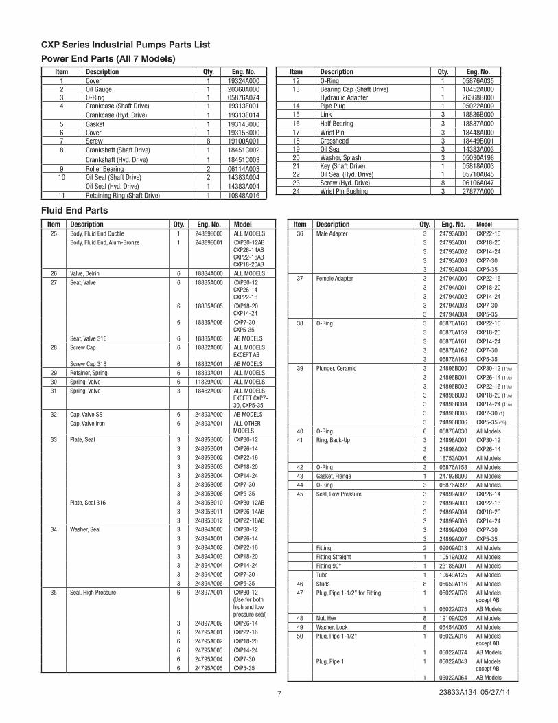
CXP Series Industrial Pumps Parts ListPower End Parts (All 7 Models)
Fluid End Parts
Item Description Qty. Eng. No.1 Cover 1 19324A0002 Oil Gauge 1 20360A0003 O-Ring 1 05876A0744 Crankcase (Shaft Drive) 1 19313E001
Crankcase (Hyd. Drive) 1 19313E0145 Gasket 1 19314B0006 Cover 1 19315B0007 Screw 8 19100A0018 Crankshaft (Shaft Drive) 1 18451C002
Crankshaft (Hyd. Drive) 1 18451C0039 Roller Bearing 2 06114A00310 Oil Seal (Shaft Drive) 2 14383A004
Oil Seal (Hyd. Drive) 1 14383A00411 Retaining Ring (Shaft Drive) 1 10848A016
Item Description Qty. Eng. No. Model25 Body, Fluid End Ductile 1 24889E000 ALL MODELS
Body, Fluid End, Alum-Bronze 1 24889E001 CXP30-12AB CXP26-14AB CXP22-16AB CXP18-20AB
26 Valve, Delrin 6 18834A000 ALL MODELS27 Seat, Valve 6 18835A000 CXP30-12
CXP26-14 CXP22-16
6 18835A005 CXP18-20 CXP14-24
6 18835A006 CXP7-30 CXP5-35
Seat, Valve 316 6 18835A003 AB MODELS28 Screw Cap 6 18832A000 ALL MODELS
EXCEPT ABScrew Cap 316 6 18832A001 AB MODELS
29 Retainer, Spring 6 18833A001 ALL MODELS30 Spring, Valve 6 11829A000 ALL MODELS31 Spring, Valve 3 18462A000 ALL MODELS
EXCEPT CXP7-30, CXP5-35
32 Cap, Valve SS 6 24893A000 AB MODELSCap, Valve Iron 6 24893A001 ALL OTHER
MODELS33 Plate, Seal 3 24895B000 CXP30-12
3 24895B001 CXP26-143 24895B002 CXP22-163 24895B003 CXP18-203 24895B004 CXP14-243 24895B005 CXP7-303 24895B006 CXP5-35
Plate, Seal 316 3 24895B010 CXP30-12AB3 24895B011 CXP26-14AB3 24895B012 CXP22-16AB
34 Washer, Seal 3 24894A000 CXP30-123 24894A001 CXP26-143 24894A002 CXP22-163 24894A003 CXP18-203 24894A004 CXP14-243 24894A005 CXP7-303 24894A006 CXP5-35
35 Seal, High Pressure 6 24897A001 CXP30-12 (Use for both high and low pressure seal)
3 24897A002 CXP26-146 24795A001 CXP22-166 24795A002 CXP18-206 24795A003 CXP14-246 24795A004 CXP7-306 24795A005 CXP5-35
Item Description Qty. Eng. No. Model36 Male Adapter 3 24793A000 CXP22-16
3 24793A001 CXP18-203 24793A002 CXP14-243 24793A003 CXP7-303 24793A004 CXP5-35
37 Female Adapter 3 24794A000 CXP22-163 24794A001 CXP18-203 24794A002 CXP14-243 24794A003 CXP7-303 24794A004 CXP5-35
38 O-Ring 3 05876A160 CXP22-163 05876A159 CXP18-203 05876A161 CXP14-243 05876A162 CXP7-303 05876A163 CXP5-35
39 Plunger, Ceramic 3 24896B000 CXP30-12 (15/8)
3 24896B001 CXP26-14 (11/2)
3 24896B002 CXP22-16 (13/8)
3 24896B003 CXP18-20 (11/4)
3 24896B004 CXP14-24 (11/8)
3 24896B005 CXP7-30 (1)
3 24896B006 CXP5-35 (7/8)
40 O-Ring 6 05876A030 All Models41 Ring, Back-Up 3 24898A001 CXP30-12
3 24898A002 CXP26-146 18753A004 All Models
42 O-Ring 3 05876A158 All Models43 Gasket, Flange 1 24792B000 All Models44 O-Ring 3 05876A092 All Models45 Seal, Low Pressure 3 24899A002 CXP26-14
3 24899A003 CXP22-163 24899A004 CXP18-203 24899A005 CXP14-243 24899A006 CXP7-303 24899A007 CXP5-35
Fitting 2 09009A013 All ModelsFitting Straight 1 10519A002 All ModelsFitting 90° 1 23188A001 All ModelsTube 1 10649A125 All Models
46 Studs 8 05659A116 All Models47 Plug, Pipe 1-1/2" for Fitting 1 05022A076 All Models
except AB1 05022A075 AB Models
48 Nut, Hex 8 19109A026 All Models49 Washer, Lock 8 05454A005 All Models50 Plug, Pipe 1-1/2" 1 05022A016 All Models
except AB1 05022A074 AB Models
Plug, Pipe 1 1 05022A043 All Models except AB
1 05022A064 AB Models
Item Description Qty. Eng. No.12 O-Ring 1 05876A03513 Bearing Cap (Shaft Drive) 1 18452A000
Hydraulic Adapter 1 26368B00014 Pipe Plug 1 05022A00915 Link 3 18836B00016 Half Bearing 3 18837A00017 Wrist Pin 3 18448A00018 Crosshead 3 18449B00119 Oil Seal 3 14383A00320 Washer, Splash 3 05030A19821 Key (Shaft Drive) 1 05818A00322 Oil Seal (Hyd. Drive) 1 05710A04523 Screw (Hyd. Drive) 8 06106A04724 Wrist Pin Bushing 3 27877A000
23833A134 05/27/12 8
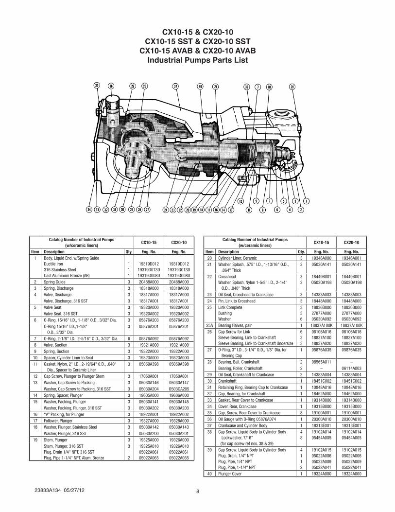
CX10-15 & CX20-10CX10-15 SST & CX20-10 SST
CX10-15 AVAB & CX20-10 AVABIndustrial Pumps Parts List
Rev 03/02
Catalog Number of Industrial Pumps(w/ceramic liners)
CX10-15 CX20-10
Item Description Qty. Eng. No. Eng. No.1 Body, Liquid End, w/Spring Guide
Ductile Iron316 Stainless SteelCast Aluminum Bronze (AB)
111
19319D01219319D013D19319D008D
19319D01219319D013D19319D008D
2 Spring Guide 3 20488A000 20488A0003 Spring, Discharge 3 18318A000 18318A0004 Valve, Discharge 3 18317A000 18317A000
Valve, Discharge, 316 SST 3 18317A001 18317A0015 Valve Seat 3 19320A000 19320A000
Valve Seat, 316 SST 3 19320A002 19320A0026 O-Ring, 15/16" I.D., 1-1/8" O.D., 3/32" Dia. 3 05876A203 05876A203
O-Ring 15/16" I.D.,1-1/8" O.D., 3/32" Dia.
3 05876A201 05876A201
7 O-Ring, 2-1/8" I.D., 2-5/16" O.D., 3/32" Dia. 6 05876A092 05876A0928 Valve, Suction 3 19321A000 19321A0009 Spring, Suction 3 19322A000 19322A000
10 Spacer, Cylinder Liner to Seat 3 19323A000 19323A00011 Gasket, Nylon, 2" I.D., 2-19/64" 0.D., .040"
Dia., Spacer to Ceramic Liner3 05059A398 05059A398
12 Cap Screw, Plunger to Plunger Stem 3 17050A001 17050A00113 Washer, Cap Screw to Packing 3 05030A146 05030A147
Washer, Cap Screw to Packing, 316 SST 3 05030A204 O503OA20514 Spring, Spacer, Plunger 3 19605A000 19606A00015 Washer, Packing, Plunger 3 05030A141 05030A145
Washer, Packing, Plunger, 316 SST 3 05030A202 05030A20316 “V” Packing, for Plunger 3 18922A001 18922A00217 Follower, Plunger 3 19327A000 19328A00018 Washer, Plunger, Stainless Steel 3 05030A142 05030A143
Washer, Plunger, 316 SST 3 05030A200 05030A20119 Stem, Plunger 3 19325A000 19326A000
Stem, Plunger, 316 SSTPlug, Drain 1/4" NPT, 316 SSTPlug, Pipe 1-1/4" NPT, Alum. Bronze
312
19325A01005022A06105022A065
19326A01005022A06105022A065
Catalog Number of Industrial Pumps(w/ceramic liners)
CX10-15 CX20-10
Item Description Qty. Eng. No. Eng. No.20 Cylinder Liner, Ceramic 3 19346A000 19346A00121 Washer, Splash, .575" I.D., 1-13/16" O.D.,
.064" Thick3 05030A141 05030A141
22 CrossheadWasher, Splash, Nylon 1-5/8" I.D., 2-1/4" O.D., .040" Thick
33
18449B001O503OA198
18449B001O503OA198
23 Oil Seal, Crosshead to Crankcase 3 14383A003 14383A00324 Pin, Link to Crosshead 3 18448A000 18448A00025 Link Complete
BushingWasher
336
18836B00027877A00005030A092
18836B00027877A00005030A092
25A Bearing Halves, pair 1 18837A100K 18837A100K26 Cap Screw for Link
Sleeve Bearing, Link to CrankshaftSleeve Bearing, Link to Crankshaft Undersize
633
06106A01618837A10018837A020
06106A01618837A10018837A020
27 O-Ring, 3" I.D., 3-1/4" O.D., 1/8" Dia. for Bearing Cap
1 05876A035 05876A035
28 Bearing, Ball, Crankshaft 2 08565A011 –Bearing, Roller, Crankshaft 2 – 06114A003
29 Oil Seal, Crankshaft to Crankcase 2 14383A004 14383A00430 Crankshaft 1 18451C002 18451C00231 Retaining Ring, Bearing Cap to Crankcase 1 10848A016 10848A01632 Cap, Bearing, for Crankshaft 1 18452A000 18452A00033 Gasket, Rear Cover to Crankcase 1 19314B000 19314B00034 Cover, Rear, Crankcase 1 19315B000 19315B00035 Cap, Screw, Rear Cover to Crankcase 8 19100A001 19100A00136 Oil Gauge with O-Ring 05876A074 1 20360A010 20360A01037 Crankcase and Cylinder Body 1 19313E001 19313E00138 Cap Screw, Liquid Body to Cylinder Body
Lockwasher, 7/16" (for cap screw ref nos. 38 & 39)
48
19102A01405454A005
19102A01405454A005
39 Cap Screw, Liquid Body to Cylinder BodyPlug, Drain, 1/4" NPTPlug, Pipe, 1/4" NPTPlug, Pipe, 1-1/4" NPT
4112
19102A01505022A00605022A00905022A041
19102A01505022A00605022A00905022A041
40 Plunger Cover 1 19324A000 19324A000
23833A134 05/27/149
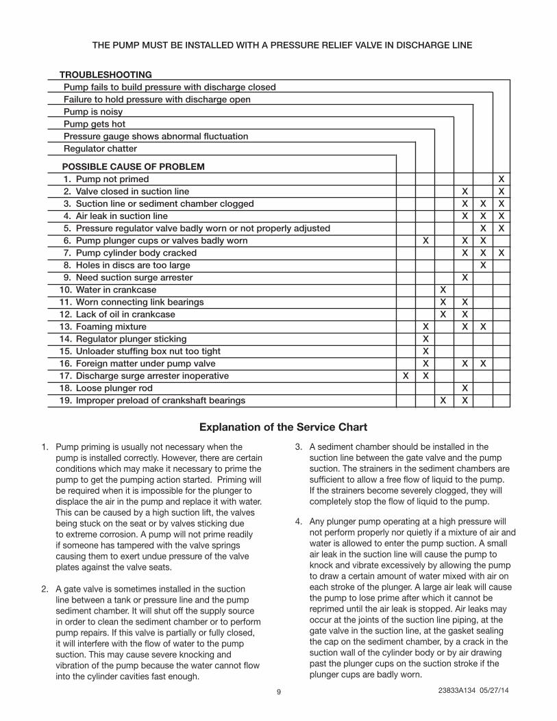
THE PUMP MUST BE INSTALLED WITH A PRESSURE RELIEF VALVE IN DISCHARGE LINE
TROUbLeShOOTING Pump fails to build pressure with discharge closed Failure to hold pressure with discharge open Pump is noisy Pump gets hot Pressure gauge shows abnormal fluctuation Regulator chatter
POSSIbLe CAUSe OF PRObLem 1. Pump not primed X 2. Valve closed in suction line X X 3. Suction line or sediment chamber clogged X X X 4. Air leak in suction line X X X 5. Pressure regulator valve badly worn or not properly adjusted X X 6. Pump plunger cups or valves badly worn X X X 7. Pump cylinder body cracked X X X 8. Holes in discs are too large X 9. Need suction surge arrester X 10. Water in crankcase X 11. Worn connecting link bearings X X12. Lack of oil in crankcase X X13. Foaming mixture X X X14. Regulator plunger sticking X 15. Unloader stuffing box nut too tight X 16. Foreign matter under pump valve X X X17. Discharge surge arrester inoperative X X 18. Loose plunger rod X19. Improper preload of crankshaft bearings X X
1. Pump priming is usually not necessary when the pump is installed correctly. However, there are certain conditions which may make it necessary to prime the pump to get the pumping action started. Priming will be required when it is impossible for the plunger to displace the air in the pump and replace it with water. This can be caused by a high suction lift, the valves being stuck on the seat or by valves sticking due to extreme corrosion. A pump will not prime readily if someone has tampered with the valve springs causing them to exert undue pressure of the valve plates against the valve seats.
2. A gate valve is sometimes installed in the suction line between a tank or pressure line and the pump sediment chamber. It will shut off the supply source in order to clean the sediment chamber or to perform pump repairs. If this valve is partially or fully closed, it will interfere with the flow of water to the pump suction. This may cause severe knocking and vibration of the pump because the water cannot flow into the cylinder cavities fast enough.
3. A sediment chamber should be installed in the suction line between the gate valve and the pump suction. The strainers in the sediment chambers are sufficient to allow a free flow of liquid to the pump. If the strainers become severely clogged, they will completely stop the flow of liquid to the pump.
4. Any plunger pump operating at a high pressure will not perform properly nor quietly if a mixture of air and water is allowed to enter the pump suction. A small air leak in the suction line will cause the pump to knock and vibrate excessively by allowing the pump to draw a certain amount of water mixed with air on each stroke of the plunger. A large air leak will cause the pump to lose prime after which it cannot be reprimed until the air leak is stopped. Air leaks may occur at the joints of the suction line piping, at the gate valve in the suction line, at the gasket sealing the cap on the sediment chamber, by a crack in the suction wall of the cylinder body or by air drawing past the plunger cups on the suction stroke if the plunger cups are badly worn.
explanation of the Service Chart
23833A134 05/27/12 10
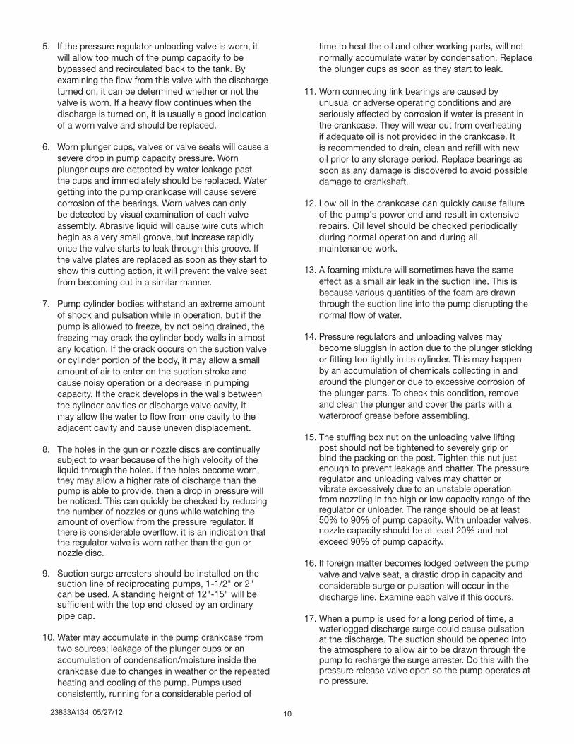
5. If the pressure regulator unloading valve is worn, it will allow too much of the pump capacity to be bypassed and recirculated back to the tank. By examining the flow from this valve with the discharge turned on, it can be determined whether or not the valve is worn. If a heavy flow continues when the discharge is turned on, it is usually a good indication of a worn valve and should be replaced.
6. Worn plunger cups, valves or valve seats will cause a severe drop in pump capacity pressure. Worn plunger cups are detected by water leakage past the cups and immediately should be replaced. Water getting into the pump crankcase will cause severe corrosion of the bearings. Worn valves can only be detected by visual examination of each valve assembly. Abrasive liquid will cause wire cuts which begin as a very small groove, but increase rapidly once the valve starts to leak through this groove. If the valve plates are replaced as soon as they start to show this cutting action, it will prevent the valve seat from becoming cut in a similar manner.
7. Pump cylinder bodies withstand an extreme amount of shock and pulsation while in operation, but if the pump is allowed to freeze, by not being drained, the freezing may crack the cylinder body walls in almost any location. If the crack occurs on the suction valve or cylinder portion of the body, it may allow a small amount of air to enter on the suction stroke and cause noisy operation or a decrease in pumping capacity. If the crack develops in the walls between the cylinder cavities or discharge valve cavity, it may allow the water to flow from one cavity to the adjacent cavity and cause uneven displacement.
8. The holes in the gun or nozzle discs are continually subject to wear because of the high velocity of the liquid through the holes. If the holes become worn, they may allow a higher rate of discharge than the pump is able to provide, then a drop in pressure will be noticed. This can quickly be checked by reducing the number of nozzles or guns while watching the amount of overflow from the pressure regulator. If there is considerable overflow, it is an indication that the regulator valve is worn rather than the gun or nozzle disc.
9. Suction surge arresters should be installed on the suction line of reciprocating pumps, 1-1/2" or 2" can be used. A standing height of 12"-15" will be sufficient with the top end closed by an ordinary pipe cap.
10. Water may accumulate in the pump crankcase from two sources; leakage of the plunger cups or an accumulation of condensation/moisture inside the crankcase due to changes in weather or the repeated heating and cooling of the pump. Pumps used consistently, running for a considerable period of
time to heat the oil and other working parts, will not normally accumulate water by condensation. Replace the plunger cups as soon as they start to leak.
11. Worn connecting link bearings are caused by unusual or adverse operating conditions and are seriously affected by corrosion if water is present in the crankcase. They will wear out from overheating if adequate oil is not provided in the crankcase. It is recommended to drain, clean and refill with new oil prior to any storage period. Replace bearings as soon as any damage is discovered to avoid possible damage to crankshaft.
12. Low oil in the crankcase can quickly cause failure of the pump's power end and result in extensive repairs. oil level should be checked periodically during normal operation and during all maintenance work.
13. A foaming mixture will sometimes have the same effect as a small air leak in the suction line. This is because various quantities of the foam are drawn through the suction line into the pump disrupting the normal flow of water.
14. Pressure regulators and unloading valves may become sluggish in action due to the plunger sticking or fitting too tightly in its cylinder. This may happen by an accumulation of chemicals collecting in and around the plunger or due to excessive corrosion of the plunger parts. To check this condition, remove and clean the plunger and cover the parts with a waterproof grease before assembling.
15. The stuffing box nut on the unloading valve lifting post should not be tightened to severely grip or bind the packing on the post. Tighten this nut just enough to prevent leakage and chatter. The pressure regulator and unloading valves may chatter or vibrate excessively due to an unstable operation from nozzling in the high or low capacity range of the regulator or unloader. The range should be at least 50% to 90% of pump capacity. With unloader valves, nozzle capacity should be at least 20% and not exceed 90% of pump capacity.
16. If foreign matter becomes lodged between the pump valve and valve seat, a drastic drop in capacity and considerable surge or pulsation will occur in the discharge line. Examine each valve if this occurs.
17. When a pump is used for a long period of time, a waterlogged discharge surge could cause pulsation at the discharge. The suction should be opened into the atmosphere to allow air to be drawn through the pump to recharge the surge arrester. Do this with the pressure release valve open so the pump operates at no pressure.
23833A134 05/27/1411
18. noisy pump operation can be caused by a loose plunger rod in the crosshead. This noise usually has a regular cadence timed with each stroke of the plunger. When this occurs, always replace both the rod and the crosshead.
19. Increased preload to the crankshaft bearings will reduce bearing life, require more power and generate more heat, while insufficient preload may cause a knock, timed with the crankshaft rotation. Check for loose bolts on the crankshaft end caps or adjust shims to obtain proper bearing preload.
1101 MYERS PARKWAY ASHLAND, OHIO, USA 44805 419-289-1144
WWW.FEMYERS.COM
Warranty Rev. 12/13
STANDARD LIMITED WARRANTYCENTRIFUGAL & RECIPROCATING PUMPS
Pentair Myers® warrants its products against defects in material and workmanship for a period of 12 months from the date of shipment from Pentair Myers or 18 months from the manufacturing date, whichever occurs first – provided that such products are used in compliance with the requirements of the Pentair Myers catalog and technical manuals.
During the warranty period and subject to the conditions set forth, Pentair Myers, at its discretion, will repair or replace to the original user, the parts that prove defective in materials and workmanship. Pentair Myers reserves the right to change or improve its products or any portions thereof without being obligated to provide such a change or improvement for prior sold and/or shipped units.
Seals, piston cups, packing, plungers, liners and valves used for handling clear, fresh, nonaerated water at a temperature not exceeding 120ºF are warranted for ninety days from date of shipment. All other applications are subject to a thirty day warranty. Accessories such as motors, engines and auxiliary equipment are warranted by the respective manufacturer and are excluded in this standard warranty. Under no circumstance will Pentair Myers be responsible for the cost of field labor, travel expenses, rented equipment, removal/reinstallation costs or freight expenses to and from the factory or an authorized Pentair Myers service facility.
This limited warranty will not apply: (a) to defects or malfunctions resulting from failure to properly install, operate or maintain the unit in accordance with the printed instructions provided; (b) to failures resulting from abuse, accident or negligence; (c) to normal maintenance services and parts used in connection with such service; (d) to units that are not installed in accordance with applicable local codes, ordinances and good trade practices; (e) if the unit is moved from its original installation location; (f) if unit is used for purposes other than for what it is designed and manufactured; (g) to any unit that has been repaired or altered by anyone other than Pentair Myers or an authorized Pentair Myers service provider; (h) to any unit that has been repaired using non factory specified/OEM parts.
Warranty Exclusions: PENTAIR MYERS MAKES NO EXPRESS OR IMPLIED WARRANTIES THAT EXTEND BEYOND THE DESCRIPTION ON THE FACE HEREOF. PENTAIR MYERS SPECIFICALLY DISCLAIMS THE IMPLIED WARRANTIES OF MERCHANTABILITY AND FITNESS FOR ANY PARTICULAR PURPOSE.
Liability Limitation: IN NO EVENT SHALL PENTAIR MYERS BE LIABLE OR RESPONSIBLE FOR CONSEQUENTIAL, INCIDENTAL OR SPECIAL DAMAGES RESULTING FROM OR RELATED IN ANY MANNER TO ANY PENTAIR MYERS PRODUCT OR PARTS THEREOF. PERSONAL INJURY AND/OR PROPERTY DAMAGE MAY RESULT FROM IMPROPER INSTALLATION. PENTAIR MYERS DISCLAIMS ALL LIABILITY, INCLUDING LIABILITY UNDER THIS WARRANTY, FOR IMPROPER INSTALLATION. PENTAIR MYERS RECOMMENDS INSTALLATION BY PROFESSIONALS.
Some states do not permit some or all of the above warranty limitations or the exclusion or limitation of incidental or consequential damages and therefore such limitations may not apply to you. No warranties or representations at any time made by any representatives of Pentair Myers shall vary or expand the provision hereof.