CWSF Combustion Testing for Oil-Fired Boiler
15
i COAL-WATER SLURRY FUEL COMBUSTION TESTING IN AN OIL-FIRED INDUSTRIAL BOILER Semiannual Technical Progress Report for the Period 02/ 15/1994 to 08/15/1994 I Bruce G. Miller, Co-Principal Investigator Alan W . Scaroni, Project Manager Nove mber 30,1994 Work Performed Under Cooperative Agreement No . DE-FC22-89PC88697 For U S . Department o f Energy Pittsburgh Energy Technology Center Pittsburgh, Pennsylvania B Y Energy an d Fuels Research Cente r The Pennsylvania State University University Park, Pennsylvania DISCLAIMER This report was prepared as an account of work sponsored by an agency of the United States Government. Neither the United Sta tes Government nor any agency thereof, nor any of their employees, makes any warranty, express or implied, or assumes any legal liability or responsi- bility for the accuracy, completeness, or usefulness of any information, apparatus, product, or process disclosed, or represents that its use would not infringe privately owned rights. Refer- ence herein to an y specific commercial product, process, or service by tra de name, trademark, manufacturer, or otherwise does not necessarily constitute or imply its endorsement, recom- mendation, or favoring by the United States Government or any agency thereof. The views and opinions of authors expressed herein do not necessarily state or reflect those of the United States Government or any agency thereof.
-
Upload
macarthur-b-monsanto -
Category
Documents
-
view
226 -
download
1
Transcript of CWSF Combustion Testing for Oil-Fired Boiler

8/3/2019 CWSF Combustion Testing for Oil-Fired Boiler
http://slidepdf.com/reader/full/cwsf-combustion-testing-for-oil-fired-boiler 1/15
COAL-WATER SLURRY FUEL COMBUSTIONTESTING IN AN OIL-FIRED INDUSTRIAL BOILER
Semiannual Technical Progress Report
for the Period 02/15/1994 to 08/15/1994
Bruce G. Miller, Co-Principal InvestigatorAlan W. Scaroni, Project Manager
November 30,1994
Work Performed Under Cooperative Agreement No. DE-FC22-89PC88697
ForU S . Department of EnergyPittsburgh Energy Technology CenterPittsburgh, Pennsylvania
BYEnergy and Fuels Research CenterThe Pennsylvania State UniversityUniversity Park, Pennsylvania
DISCLAIMER
This report was prepared as an account of work sponsored by an agency of the UnitedStatesGovernment. Neither the United Sta tes Government nor any agency thereof, nor anyof theiremployees, makes any warranty, expressor implied, or assumes any legal liability orresponsi-bility for the accuracy, completeness,or usefulness of any information, apparatus, product, orprocess disclosed, or represents that its use would not infringe privately owned rights. Refer-ence herein to an y specific commercial product,process, or service by tra de name, trademark,manufacturer, or otherwise does not necessarily constitute or imply its endorsement, recom-mendation, or favoring by the United States Governmentor any agency thereof. The viewsand opinions of authors expressed herein do not necessarily state or reflect those of theUnited States Governmentor any agency thereof.

8/3/2019 CWSF Combustion Testing for Oil-Fired Boiler
http://slidepdf.com/reader/full/cwsf-combustion-testing-for-oil-fired-boiler 2/15
- DISCLAIMER
:.. ..ll
This report was prepared as an account of work sponsored by the United States
&vemrnent. Neither the United States Government nor the United States Department of Energy,
nor any of their employees, nor any of their contractors, subcontractors, or their employees makes
any warranty, express or implied, or assumes any 1egal.liabiIity or responsibility for the accuracy,
completeness, or usefulness of any information, apparatus, product, or process disclosed, or
represents that its use would not infringe privately owned rights.

8/3/2019 CWSF Combustion Testing for Oil-Fired Boiler
http://slidepdf.com/reader/full/cwsf-combustion-testing-for-oil-fired-boiler 3/15
DISCLAIMER
Portions of this document ma I be illegiblein electronic image products. Images areproduced from the best available originaldocument.

8/3/2019 CWSF Combustion Testing for Oil-Fired Boiler
http://slidepdf.com/reader/full/cwsf-combustion-testing-for-oil-fired-boiler 4/15
TABLE OF CONTENTS
~ C u T I v E UMMARY
1.0 INTRODUCTION ...........................................................2.0 PHASEIV: ADVANCEDSYSTEMTESTS ...........................
........................................... ....... ... .....
2.1
2 .22.3NEXT SEMIANNUAL PERIOD A(3TIvITIES
Task 1. Procurement and Installation of a Burnerand Superheater .
Task 2. Construction of a CWSF Preparation Facility .Task 3. Installation of an Advanced Flue Gas Treatment System. .
3.0 .4.0 REFERENCES .............. ................................ .................5.0 ACKNOWLEDGMENTS. .... .... ... ............ .... ............ .... .......
Fw2
iv1
3
8/3/2019 CWSF Combustion Testing for Oil-Fired Boiler
http://slidepdf.com/reader/full/cwsf-combustion-testing-for-oil-fired-boiler 5/15
iv
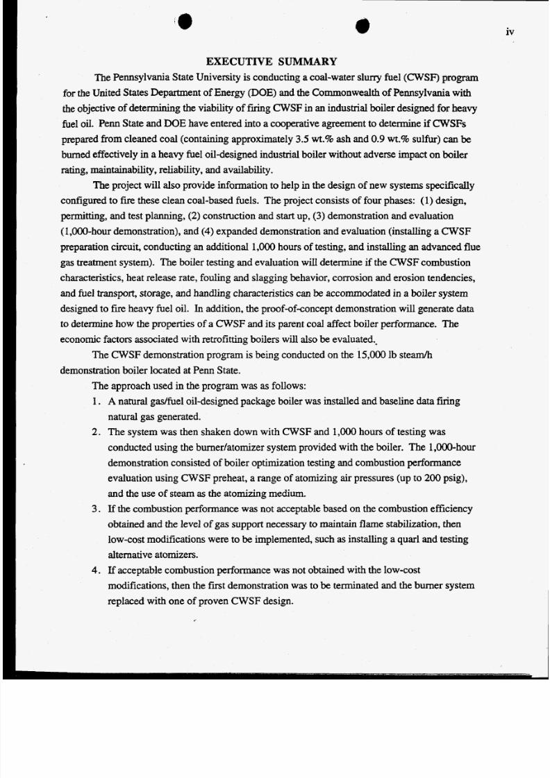
EXECUTIVE SUMMARYThe Pennsylvania State University is conducting a coal-water slurry fuel (CWSF) program
for the United States Department of Energy (DOE) nd the Commonwealth of Pennsylvania with
the objective of determining the viability of frring CWSF in an industrial boiler designed for heavy
fuel oil. Penn State and DOE have entered into a cooperative agreement to determine if CWSFs
prepared from cleaned coal (containing approximately 3.5 wt.% ash and 0.9 wt.% sulfur) can be
burned effectively in a heavy fuel oildesigned industrial boiler without adverse impact on boiler
rating, maintainability, reliability, and availability.
configured to fire these clean coal-based fuels. The project consists of four phases: (1) design,
permitting, and test planning, (2) construction and start up, (3) demonstration and evaluation
(1,000-hour demonstration), and (4) expanded demonstration and evaluation (installing a C W S Fpreparation circuit, conducting an additional 1,OOO hours of testing, and installing an advanced flue
gas reatment system). The boiler testing and evaluation wiII determine if the C W S F ombustioncharacteristics, heat release rate, foulingand slagging behavior, corrosion and erosion tendencies,
and fuel transport, storage, and handling characteristics can be accommodated in a boiler system
designed to fire heavy fuel oil. In addition, the proof-of-concept demonstration will generate data
to determine how the properties of a CWSF and its parent coal affect boiler performance. The
economic factors associated with retrofitting boilers will also be evaluated..
The CWSF emonstration program is being conducted on the 15,000 lb steam/h
demonstration boiler located at Penn State.
The approach used in the program was as follows:
The project will also provide information to help in the design of new systems specifically
1 .
2.
3.
4.
A natural gas/fuel oildesigned package boiler was installed and baseline data firingnatural gas generated.
The system was then shaken down with CWSF and 1OOO hours of testing was
conducted using the burner/atomizer system provided with the boiler. The 1,OOO-hourdemonstration consisted of boiler optimization testing and combustion performance
evaluation using CWSF preheat, a range of atomizing air pressures (up to 200 psig),
and the use of steam as the atomizing medium.
If the combustion performance was not acceptable based on the combustion efficiency
obtained and the level of gas support necessary to maintain flame stabilization, thenlow-cost modifications were to be implemented, such as installing a quarl and testing
alternative atomizers.
If acceptable combustion performance was not obtained with the low-cost
modifications, then the first demonstration was to be terminated and the burner system
replaced with one of proven CWSF design.

8/3/2019 CWSF Combustion Testing for Oil-Fired Boiler
http://slidepdf.com/reader/full/cwsf-combustion-testing-for-oil-fired-boiler 6/15
V
5 . In addition to the advanced burner system, a superheater tube and advanced flue gas
The first three steps (Le., the first demonstration) have been completed and the combustion
cleanup system were to be nstalled for the second 1,OoO-hour demonstration.
performance of the burner that was provided with the boiler has been determined to be
unacceptable. Consequently, the first demonstration has been concluded at 500 hours. The
second demonstration (phase IV) will be conducted after a proven CWSFdesigned burner isinstalled on the boiler.
Prior to the second demonstration, a C W S F reparation circuit is being constructed.
During this reporting period, he construction of the CWSF preparation circuit (as well as a dry,
micronized coal circuit) continued. The C W S F reparation circuit will be completed by November
1,1994.
Additional activities included receiving a coal-designed burner and installing t on the
demonstration boiler; and working with DOEin selecting pollution control systems to install on the
boiler.

8/3/2019 CWSF Combustion Testing for Oil-Fired Boiler
http://slidepdf.com/reader/full/cwsf-combustion-testing-for-oil-fired-boiler 7/15
1.0 INTRODUCTIONThe Pennsylvania State University is conducting a coal-water slurry fuel (CWSF) program
for the United States Department of Energy (DOE) nd the Commonwealth of Pennsylvania with
the objective of determining the viability of firing CWSF in an ndustrial boiler designed for heavy
fuel oil. Penn State and DOE have entered into a cooperative agreement to determine if CWSFsprepared from cleaned coal (containing approximately 3.5 wt.% ash and 0.9 wt.% sulfur) can be
burned effectively in a heavy fuel oildesigned industrial boiler without adverse impact on boiler
rating, maintainability, refiability, and availability. The project will also provide infoxmation to
help in the design of new systems specifically configured to fire these clean coal-based fuels.
The project consists of four phases: (1) design, permitting,and test planning, (2)
construction and start up, (3 ) demonstration and evaluation (1,000-hour demonstration), and (4)
expanded demonstration and evaluation (additional 1,0oO hours of testing). The boiler testing and
evaluation will determine if the CWSF combustion characteristics, heat release rate, fouling and
slagging behavior, corrosion and erosion tendencies, and fuel transport, storage, and handling
characteristics can be accommodated in a boiler system designed to fire heavy fuel oil. In addition,
the proof-of-concept demonstration will generate data to determine how the properties of a CWSFand its parent coal affect boiler performance. The economic factors associated with retrofitting
boilers will also be evaluated.
The project consists of four phases as previously mentioned. Following is an outline of the
Phase I: Design, Permitting, and Test Planning
project tasks that comprise the four phases:
Task 1. DesignTask2 Permitting
Task 3. Test Planning
Phase II: Construction and Start Up
Task 1. Host Site ReadinesdBoiler Retrofit
Task 2. CWSF Preparation
Task 3. Boiler Performance Prediction
Task 4. Shakedown Testing
Task 1. Test BurnPhase III: Demonstration and Evaluation
Subtask 1.a. CWSF combustion performance
Subtask 1 b. Slagging/fouling propensity; corrosion characteristics
Subtask 1 c. Erosion characteristics
Subtask 1.d. Fuel transport, storage, and handling characteristics
Task 2. Evaluation of Retrofit Economics
8/3/2019 CWSF Combustion Testing for Oil-Fired Boiler
http://slidepdf.com/reader/full/cwsf-combustion-testing-for-oil-fired-boiler 8/15
eTask 3. Project Report
Task 1. Procure and Install Burner and Superheater
Task 2. Construction of a CWSF Preparation Facility
Task 3. Installation of an Advanced Flue Gas Treatment SystemTask 4. 1,000-How Test
Task 5. Final Report
Phase IV: Advanced System Tests
Penn State began a coal-water slurry fuel (CWSF) research and development program in
1984 with the ultimate goal of facilitathg the replacement of petroleum-based fuels with coal-based
fuels in fuel oil-fired (designed) boilers. The Pennsylvania legislature appropriated funds in 1984for the construction of a demonstration CWSF boiler with a capacity of approximately 15,000 lb
steam/h at 300 psig on the University Park campus of Penn State. The project goal was to conduct
a demonstration of the use of C W S Fderived from Pennsylvania coal. The boiler performance was
required to be environmentally acceptable and the testing was to evaluate the effects of long-term
firing with CWSF on boiler performance. From a commercialization viewpoint, it was considered
necessary to demonstrate at the industrial scale the technical feasibility of retrofitting existing fuel
oil-fired units to bum CWSF, articularly in the commercial and light-industrial sectors. State
funding was also provided for the installation of a 1,000 lb steam/h (nominally rated)
Cleaver-Brooks A-frame watertube boiler (Kinneman et al, 1988) to investigate: the effect of
boiler operating parameters on combustion performance (Miller et al, 1988); automation of the
firing of CWSF, articularly with respect to start up and shutdown procedures but also for
optimizing boiler performance (Wincek et al, 1989); testing candidate CWSFs (Miller et al, 1991);and providing the necessary research support and operator training prior to start up of the
demonstration unit. The CWSF demonstration program is being conducted on the 15,000 lb
steam/h demonstration boiler.
The approach used in the program was as follows:
1. Install a natural gadfuel oildesigned package boiler and generate baseline data fuing
natural gas.
2 . Shake down the system with C W S F nd begin the first 1,OOO hours of testing using the
burner/atomizer system provided with the boiler. The first 1,OOO-hour demonstration
was to consist of boiler optimization testing and combustion performance evaluation
using CWSF reheat, a range of atomizing air pressures (up to 200 psig as compared to
the 100 psig boiler manufacturer design pressure), and using steam as the atomizing
medium.
3. If the combustion performance was not acceptable based on the combustion efficiency
obtained and the level of gas support necessary to maintain flame stabilization, then
2

8/3/2019 CWSF Combustion Testing for Oil-Fired Boiler
http://slidepdf.com/reader/full/cwsf-combustion-testing-for-oil-fired-boiler 9/15
elowcost modifications were to be implemented, such as installing a qual and testing
alternative atomizers.
modifications, then the fmt demonstration was to be texminated and the burner system
replaced with one of proven CWSF design.
cleanup system were to be installed for the second 1,OOo-hour demonstration.
4 . If acceptable combustion performance was not obtained with the lowcost
5 . In addition to the advanced burner system, a superheater tube and advanced flue gas
The fmt three steps (Le., the fmt demonstration) have been completed and the combustion
performance of the burner that was provided with the boiler has been determined to be
unacceptable. Consequently, the fmt demonstration (Phases I-m) has been concluded at 50 0
hours and the results have been presented elsewhere (Miller, et al 1993). The second
demonstration (Phase IV) will be conducted after a proven CWSFdesigned burner is installed on
the boiler.
A summary of Phase IV s presented in Section 2.0. Activities planned for the next
semiannual period are given in Section 3.0. References are contained in Section 4.0 and
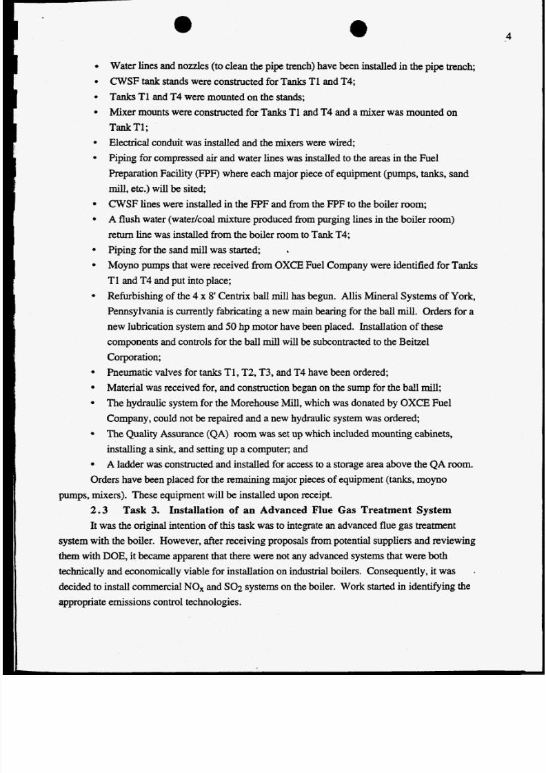
acknowledgments are given in Section 5.0. The milestone schedule for Phase IV s shown in
Figure 1, and Table 1 contains the milestone description for the entire project.
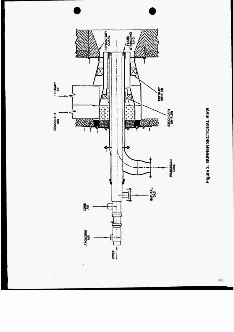
2 . 0 ADVANCED SYSTEM TESTS2 . 1During this reporting period, a burner was procured from Energy and Environmental
Research Corporation (in conjunction with another program (Cooperative Agreement No. DE-
FC22-92PC92162) that has the capability of firing natural gas and CWSF or dry, micronized coal.It is a low-NO, burner and a sectional view is shown in Figure 2. Details of the burner were given
in the previous semiannual report (Miller et al., 1994). Currently the burner is being operated in its
dry, micronized coal mode for another program (Cooperative Agreement No. DE-FC22-
92PC92162). The atomizer will be installed prior to the Phase IV est (first and second quarter of
1995).
No work was conducted on the procurement and installation of the superheater this
2 . 2 Task 2. Construction of CWSF Preparation FacilityConstruction of the CWSF preparation circuit continued during this reporting period.
Task 1. Procurement and Installation of a Burner and Superheater
reporting period. The superheater will be installed prior to the Phase N est.
Figure 3 is a schematic diagram of the CWSF preparation circuit. The installation of the CWSF
circuit is being conducted in conjunction with another program (Cooperative Agreement No. DE-FC22-92PC92 162).
below:
Items that have been, or are in the process of being, installed or constructed are listed
3
8/3/2019 CWSF Combustion Testing for Oil-Fired Boiler
http://slidepdf.com/reader/full/cwsf-combustion-testing-for-oil-fired-boiler 10/15
0
0
0
0
0
0
0
0
0
0
0
0
0
0
e
0
4
Water lines and nozzles (to clean the pipe trench) have been installed in the pipe trench;
CWSF tank stands were constructed for Tanks T1 and T4;
Tanks T1 and T4 were mounted on the stands;
Mixer mounts were constructed for Tanks T1 and T4 and a mixer was mounted on
Tank T1;Electrical conduit was installed and the mixers were wired;
Piping for compressed air and water lines was installed to the areas in the Fuel
Preparation Facility (FPF) where each major piece of equipment (pumps, tanks, and
mill, etc.) will be sited;
CWSF lines were installed in the FPF and from the FPF to the boiler room;
A flush water (water/coal mixture produced h m urging lines in the boiler room)
return line was installed from the boiler room to Tank T4;
Piping for the sand mill was started;
Moyno pumps that were received from OXCEFuel Company were identified for Tanks
T1 and T4 and put into place;
Refurbishing of the 4 x 8' Centrix ball mill has begun. Allis Mineral Systems of York,
Pennsylvania is currently fabricating a new main bearing for the ball mill. Orders for a
new lubrication system and 50 hp motor have been placed. Installation of these
components and controls for the ball mill will be subcontracted to the Beitzel
Corporation;
Pneumatic valves for tanks T1, T2, T3, and T4 have been ordered;
Material was received for, and construction began on the sump for the bd l mill;The hydraulic system for the Morehouse Mill, which was donated by OXCE Fuel
Company, could not be repaired and a new hydraulic system was ordered;
The Quality Assurance (QA) mom was set up which included mounting cabinets,
installing a s ink , and setting up a computer, and
A ladder was constructed and installed for access to a storage area above the QA room.
.
Orders have been placed for the remaining major pieces of equipment (tanks, moyno
2.3It was the original intention of this task was to integrate an advanced flue gas treatment
pumps, mixers). These equipment will be installed upon receipt.
Task 3. Installation of an Advanced Flue Gas Treatment System
system with the boiler. However, after receiving proposals from potential suppliers and reviewing
them with DOE, it became apparent that there were not any advanced systems that were both
technically and economically viable for installation on industrial boilers. Consequently, it was
decided to install commercial NO, and SO2 systems on the boiler. Work started in identifying the
appropriate emissions control technologies.
.

8/3/2019 CWSF Combustion Testing for Oil-Fired Boiler
http://slidepdf.com/reader/full/cwsf-combustion-testing-for-oil-fired-boiler 11/15

8/3/2019 CWSF Combustion Testing for Oil-Fired Boiler
http://slidepdf.com/reader/full/cwsf-combustion-testing-for-oil-fired-boiler 12/15
Jvlilestone
Phase ITask 1, No. ITask 2, No. 1Task 3, No. 1
Phase I1Task 1, No. 1Task 1, No. 2Task I , No. 3Task 2, No. 1Task 2, No. 2Task 3, No. 1Task 4, No. 1
Task4,
No. 2Phase IIITask 1, No. 1
Subtask la, No. 1Subtask la, No. 2Subtask la , No. 3Subtask lb , No. 1Subtask lb , No. 2Subtask lb, No. 3Subtask lb, No. 4
Subtask lb , No. 5
Subtask Ib, No. 6Subtask lb , No. 7Subtask IC, No. 1Subtask IC, No. 2Subtask IC, No . 3Subtask IC , No. 4Subtask IC, No. 5
Subtask IC ,No. 6Subtask Id , No. 1Subtask Id , No. 2Subtask Id, No. 3
Task 2, No. 1Task3,No. 1
Phase IVTask 1, No. 1Task 1, No. 2Task2,No. 1Task 2, No. 2Task 3, No. 1Task 4, No. 1Task 5, No , 1
Table 1. Milestone Description
Identify equipment and diagnostic instrumentationReview present permitDevelop C W S F pecifications, identify operatingprocedures, prepare detailed test plan
Buildinghiler construction and installation let for bidsBuildinglboiler construction and installation awardedPrepare site, install boiler and auxiliary equipmentIdentify coal for CWSF preparationPrepare CWSF for demonstrationPredict boiler performanceShakedown boiler and auxiliary equipment
Generate baseline data on gas
Perform demonstration300-hour demonstration milestone500-hour demonstration milestoneRedefine CWSF specificationsDevelop deposition and corrosion test planDesign suction pyrometerConstruct suction pyrometerDeposition characterization equipment design andspecificationAcquisition of baseline data for spectroscopic analysisof deposits; acquisition of baseline data for corrosion of
tubes by ash componentsCoupon testing in boilerComplete deposition and corrosion testingDevelop erosion test planComplete research boiler erosion evaluationFull-scale erosion technique decisionDesign probe for full-scale erosion studyConstruct erosion probeComplete erosion modelingIdentify viscometerComplete preliminary viscosity and stability testsComplete viscosity and stability testsComplete economic evaluationComplete project report
Procure and install burnerProcure and install superheaterComplete construction of Fuel Preparation FacilityInstall and shake down CWSFpreparation circuitInstall flue gas treatment systemComplete 1 OOO-hr testComplete final report
PlannedComDletioq
w
09/15/89091 15/8910/15/89
1011 8/89133 1/8904/01/9109/30/9004/01/9106/15/9 10413 119 1
0513 119 1
0713 1/921013 1/9201/15/931O/15/8906/01/9010/01/900 110 119 1
0813 119 1
10/31/9201/15/93101 15/890810 1I901010 1 900 110 119 10510 119 1
01/15/931011 5/89081 15/9011/30/9201/15/930310 1 93
0411 5/9412/31/940813 1/9311/01/9412/31/9406/30/950910 1/95
Actual
Q&ComDIetioq
0911 5/8909/15/8902/15/93
1011 8/8903/23/9001/31/9209/30/901011 3/92OD0 1/9206/30/92
09/30/9 1
0713 1/9211/13/9201/15/931011 5/8908/0 1/901010 1/9002/15/91
0811 5/92
11/13/9201/15/931011 5/8908/01/9010/01/90OU15/9110/15/9 10611 5/931011 5/8909/15/9011/30/920 1115/9306l2 1/93
05/09/94
0813 1/93

8/3/2019 CWSF Combustion Testing for Oil-Fired Boiler
http://slidepdf.com/reader/full/cwsf-combustion-testing-for-oil-fired-boiler 13/15
. . . . . . . . . . . . . . . - ......... __- - - - I -I) A
4 . . . . . . . . . . . . . . . . . . . . . . . . . . . . . . . . . . . . . . . . . . . . . . . - - ..
~~~
..... ................................... -.
E - - ......... - I - .I . -
4 ' - - '
E ... .- - ....
. . . . . .- .--
- I ... -- - - -
E .... ..... _. .- .- .......... .I - - -.- -- - - -s - - l
w
-3jil
'c1E
Q)v)
8Y
8/3/2019 CWSF Combustion Testing for Oil-Fired Boiler
http://slidepdf.com/reader/full/cwsf-combustion-testing-for-oil-fired-boiler 14/15
1
t iii 'iiiiiii1
$
iIi
- -i
I
zs;i
Y
2
I-
u)
9
awzp:3m
,
03

8/3/2019 CWSF Combustion Testing for Oil-Fired Boiler
http://slidepdf.com/reader/full/cwsf-combustion-testing-for-oil-fired-boiler 15/15