CWM Fac Pond Tank Design - dec.ny.gov
30
TANK SYSTEM DESIGN ASSESSMENT REPORT FOR FAC POND 5 TANK T-9001 [NOTE: To be added to the Permit in its entirety] NYSDEC OHMS Document No. 201469232-00047
Transcript of CWM Fac Pond Tank Design - dec.ny.gov

TANK SYSTEM DESIGN ASSESSMENT REPORT
FOR FAC POND 5 TANK T-9001
[NOTE: To be added to the Permit in its entirety]
NYSDEC OHMS Document No. 201469232-00047

Tank System Design and Assessment Report for
Fac Pond 5 Tank T-9001
CWM Chemical Services, LLCModel City, New York
April 2013(Revised August 2013)
(Revised November 2013)
Prepared by
EnSol, Inc.Environmental Solutions
NYSDEC OHMS Document No. 201469232-00047

NYSDEC OHMS Document No. 201469232-00047

R E P O R T
Tank System Design and Assessment Report for
Fac Pond 5 Tank T-9001
Prepared by EnSol, Inc.
661 Main Street Niagara Falls, New York 14301
CWM Chemical Services, LLCModel City, New York
April 2013(Revised August 2013)
(Revised November 2013)
NYSDEC OHMS Document No. 201469232-00047

ENSOL, INC. November 2013 p r o f e s s i o n a l e n g i n e e r i n g / b u s i n e s s c o n s u l t i n g i T-9001 Design Assessment Report Rev2
Table of Contents
Section 1. Introduction ............................................................................................................... 1-1
1.1 General Site Information.................................................................................................. 1-1 1.2 Project Purpose and Objective ........................................................................................ 1-1 1.3 Tank Inspection/Assessment Requirements and Guidelines.......................................... 1-2
Section 2. Tank Location and Description................................................................................ 2-1
2.1 Location ........................................................................................................................... 2-1 2.2 Dimensions and Capacity................................................................................................ 2-1 2.3 Structural Support and Foundation.................................................................................. 2-1 2.4 Materials of Construction................................................................................................. 2-1 2.5 Miscellaneous Attachments............................................................................................. 2-1 2.6 Process Description, Piping, and Pumping System ........................................................ 2-1 2.7 Overpressure/Vacuum and Overfill Protection ................................................................ 2-2 2.8 Protective Coatings ......................................................................................................... 2-2 2.9 Secondary Containment and Leak Detection.................................................................. 2-2
Section 3. Assessment and Certification.................................................................................. 3-1
3.1 Design and Record Information....................................................................................... 3-1 3.2 Summary and Conclusions.............................................................................................. 3-1
Figures 1. Regional Location Map 2. Facility Location Detail 3. Facility Layout Plan Appendices A. Proposed Fac Pond 5 Permit Drawings (Arcadis) B. Proposed Secondary Containment Storage Tank Information (Snyder)
• Tank Product Data • Snyder Specification #199901 • Tank Chemical Resistance Chart • Fac Pond Water Physical / Chemical Analysis
C. Proposed Pump, Piping, and Equipment Information
• Secondary Containment Submersible Pump Data (Goulds) • Pump Cart Shop Drawing (CWM) • Flex Hose Cut Sheet (Goodyear) • Level Transmitter (Viatram) • Programmable Limit Alarm (Moore) • High Level Switch (Madison) • Turbine Flow Sensor and Flow Meter Cut Sheet (Seametrics) • HDPE Pipe Data (Phillips Chevron) • Ball Valve & Hose Adapter (Grainger)
NYSDEC OHMS Document No. 201469232-00047

ENSOL, INC. November 2013 p r o f e s s i o n a l e n g i n e e r i n g / b u s i n e s s c o n s u l t i n g 1-1 T-9001 Design Assessment Report Rev2
1. Introduction
1.1 General Site Information
CWM Chemical Services, LLC (CWM) owns and operates a commercial hazardous waste treatment, storage, and disposal facility (TSDF) in Model City, Niagara County, New York. This TSDF began operating in 1972 as ChemTrol Pollution Services, Inc. Due to corporate acquisitions and name changes, CWM, a subsidiary of Waste Management, Inc., is the present owner and operator of the facility. Waste Management, Inc. is based in Houston, Texas. The facility is located on Balmer Road in Model City, New York, approximately 1.9 miles east of New York State Route 18 (Creek Road), and occupies land in the towns of Lewiston and Porter. A Regional Location Map and Facility Location Detail are presented in Figures 1 and 2, respectively. All existing waste management units on the site are located within the Town of Porter. The contiguous property along Balmer Road is also the location of offices for the Administrative, Sales and Marketing, Data Processing, Accounting, Environmental, and Engineering Departments. The CWM Model City facility is permitted as a TSDF under the Resource Conservation and Recovery Act (RCRA). Numerous units at the site are used to store, treat, and dispose of a variety of liquid and solid organic and inorganic hazardous wastes. Storage, treatment, and disposal capabilities include an Aqueous Wastewater Treatment System (AWTS) utilizing chemical, physical, and biological treatment processes from which treated wastewater is discharged to the Niagara River in accordance with the facility's State Pollutant Discharge Elimination System (SPDES) Permit; secure landfilling of approved waste solids and semisolids, including polychlorinated biphenyls (PCBs); waste stabilization; container and tank storage; transformer decommissioning; and PCB treatment and storage. Figure 3 presents a Facility Layout Plan.
1.2 Project Purpose and Objective
The purpose of this report is to present applicable design and construction information for the proposed Fac Pond 5 secondary containment storage tank (SCS Tank), and to document the results of an assessment conducted by EnSol, Inc. (EnSol) for this tank system. The proposed SCS Tank is a double walled pre-manufactured High Density Linear Polyethylene (HDLPE) storage tank, to be located in the Fac Pond Riser House at Fac Pond 5. Fac Pond 5 will be a newly constructed surface impoundment constructed with a double liner system. This will include leachate collection and removal system between such liners. Any liquids that reach the secondary containment will drain to a low point or sump and be pumped into the proposed SCS Tank. The SCS Tank will be housed within a Riser House at the top of the perimeter embankment of the fac pond. The proposed tank will be known as T-9001. It is intended that this report be used by CWM to aid in obtaining an approval from the New York State Department of Environmental Conservation (NYSDEC) as per 6 NYCRR 373-2.10(c) to install the tank, piping, and appurtenances, and to operate the SCS Tank system for the purpose stated above. The objective of the assessment is to satisfy the applicable State and Federal Regulations for the installation of new tank systems as required by CWM's Sitewide Part 373 Permit #9-2934-020022/00097. As required by 6 NYCRR 373-2.10(c)(1), the owner or operator of a new tank system must obtain and submit to the NYSDEC a written assessment attesting that the tank system has sufficient structural integrity and is acceptable for storing hazardous waste.
NYSDEC OHMS Document No. 201469232-00047

ENSOL, INC. November 2013 p r o f e s s i o n a l e n g i n e e r i n g / b u s i n e s s c o n s u l t i n g 1-2 T-9001 Design Assessment Report Rev2
The following information is included in this report for the proposed SCS Tank system: location, configuration, design parameters, operating procedures, materials of construction, provisions for secondary containment and leak detection, and the results of EnSol’s assessment.
1.3 Tank Inspection/Assessment Requirements and Guidelines
An assessment of the subject tank system is required by State and Federal Regulations listed under 6 NYCRR 373-2.10(c) and 40 CFR 264.192, respectively, pertaining to Hazardous Waste Management Facilities. These regulations identify the assessment requirements to be met and associated activities to be performed related to the design and installation of new tank systems or components. The assessment procedure also requires an evaluation of the system design, as it pertains to the containment and detection of releases, in accordance with State and Federal Regulations listed under 6 NYCRR 373-2.10(d) and 40 CFR 264.193, respectively. Additional site-specific permit requirements may also be developed between the owner and the regulatory agencies, such as the CWM Tank and Sump Assessment Schedule included in CWM's Sitewide Permit. In addition to general regulations and/or site-specific permit requirements, there are several recommended or applicable guidance documents pertaining to tank inspections, assessments, and design. EnSol personnel have used the primary guidance documents referenced below to conduct previous site inspections, assessments, and designs for tank systems, and to aid in the design and assessment contained herein.
i. Guide for Inspection of Refinery Equipment, Chapter XIII, Atmospheric and Low Pressure Storage Tanks, American Petroleum Institute (API) publication, 4th edition, 1991.
ii. Tank Inspection, Repair, Alteration, and Reconstruction, API Standard 653, 3rd Edition, December
2001.
iii. Requirements for Tank and Container Storage, NYSDEC, Technical and Administrative Guidance Memorandum No. 3019, April 23, 1991.
iv. Concrete Secondary Containment for Tank and Container Storage, NYSDEC, Technical and
Administrative Guidance Memorandum No. 3021, March 11, 1991.
v. Chemical Plant and Petroleum Refinery Piping, American Society of Mechanical Engineers (ASME) Standard B31.3-1990
NYSDEC OHMS Document No. 201469232-00047

ENSOL, INC. November 2013 p r o f e s s i o n a l e n g i n e e r i n g / b u s i n e s s c o n s u l t i n g 2-1 T-9001 Design Assessment Report Rev2
2. Tank Location and Description
2.1 Location
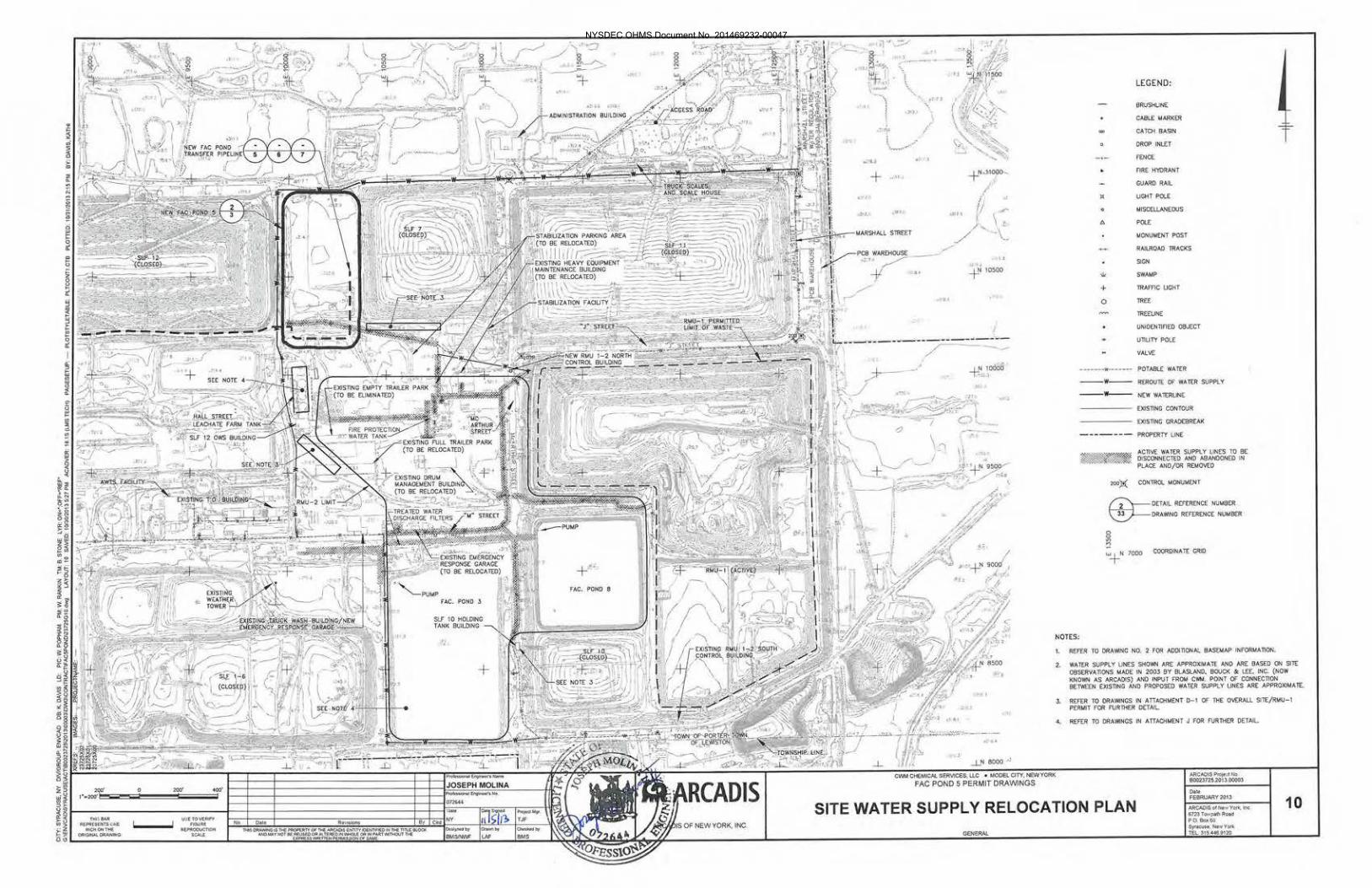
The SCS Tank will be located in the proposed Fac Pond Riser House located along the perimeter berm of Fac Pond 5. Fac Pond 5 will be constructed new as part of the RMU-2 development project. Fac Pond 5 will be located between closed landfills SLF 12 and SLF 7 to the north of the existing Leachate Tank Farm. The location of the fac pond is shown on the set of design drawings by Arcadis included in Appendix A.
2.2 Dimensions and Capacity
The SCS Tank will be a single chamber, dual walled, cylindrical vessel with a flat bottom and a flat roof, with exterior dimensions of 6 feet - 4 inches diameter x 8 feet - 10 inches high. The design capacity of the tank is 1,100 gallons.
2.3 Structural Support and Foundation
The tank will be a free standing flat bottomed tank which will be supported by a 6-inch thick reinforced concrete slab system within the Riser House. The concrete slab will be underlain with a minimum 6-inch thick layer of compacted stone. The tank will not require additional supports or tie-downs as it will not be subject to any wind, snow, significant seismic, or other external loads, however, as an added measure, tie-downs will be included to anchor the tank to the Riser House floor slab using the manufacturer provided cable restraint system or an or-equal approved system..
2.4 Materials of Construction
The SCS Tank is a 1,100 gallon High Density Linear Polyethylene (HDLPE) tank manufactured by Snyder Industries, Inc. The design shell thickness will be a minimum 0.187 inches (3/16 inch). Refer to Appendix B for additional design and construction specifications and manufacturers information.
2.5 Miscellaneous Attachments
As shown on the reference drawings in Appendix A, the SCS Tank will have one inlet and one outlet on the top of the tank and one top vent opening with breather valve. Nozzle diameters will all be 2-inches. The tank will also include an 18-inch top manway.
2.6 Process Description, Piping, and Pumping System
The proposed use of the SCS Tank will be for the storage of liquid generated from the secondary collection sump in Fac Pond 5. The liquid will be pumped up the 18-inch diameter HDPE sideslope riser pipe from the secondary collection sump via a submersible pump. The pump will be connected to the tank piping using a 2-inch diameter chemical flex hose. The tank will be equipped with a 2-inch diameter HDPE inlet pipe and flow meter to measure any liquid that is pumped into the tank. The tank will store the liquid until it can be pumped out of the tank via vacuum truck utilizing the 2-inch dip tube on the top of the tank. This liquid will then be transferred to the on-site AWTS for processing.
NYSDEC OHMS Document No. 201469232-00047

ENSOL, INC. November 2013 p r o f e s s i o n a l e n g i n e e r i n g / b u s i n e s s c o n s u l t i n g 2-2 T-9001 Design Assessment Report Rev2
2.7 Overpressure/Vacuum and Overfill Protection
Primary overpressure/vacuum protection, under normal operating conditions (i.e., tank filling, content withdrawal, and diurnal breathing), will be provided by a 2-inch diameter pipe vent open to the atmosphere. Overfill protection for the tank is provided by a high level float switch inside the tank. This switch will inhibit the inlet pump and signal an alarm light on the exterior of the building.
2.8 Protective Coatings
The tank is constructed of HDLPE resin and is inherently resistant to corrosion or chemical degradation by the anticipated liquids (Fac pond water) without the addition of any protective coatings. Chemical analysis of Fac Pond water was provided by CWM and is included in Appendix B. The tank will be housed within the Riser House, which is a heated structure; therefore, the tank will not require any additional external coatings to protect it from UV degradation or other environmental factors. Manufacturer’s Specifications, including chemical resistance data and chart are included in Appendix B.
2.9 Secondary Containment and Leak Detection
Secondary containment for the SCS Tank is provided by a double walled tank construction. In the event of a leak from the primary tank, the liquid would be contained within the secondary tank. The tank’s double walled design meets all volume requirements for secondary containment and will provide a minimum of 100% of the normal fill capacity of the primary tank. Leak detection for the SCS Tank will be provided by an electronic moisture sensor placed within the interstitial space of the double walled tank. This sensor will activate a visible alarm (light) on the exterior of the Riser House which will be seen by visual means through daily inspection by CWM personnel. The tank sides, top, nozzles, and system piping are all visible for easy inspection. A drain valve located near the bottom of the secondary containment tank wall will also be available to check for liquids in the secondary containment area as an additional measure.
NYSDEC OHMS Document No. 201469232-00047

ENSOL, INC. November 2013 p r o f e s s i o n a l e n g i n e e r i n g / b u s i n e s s c o n s u l t i n g 3-1 T-9001 Design Assessment Report Rev2
3. Assessment and Certification EnSol conducted an assessment and review of the proposed SCS Tank system components at CWM's Model City facility in order to assess the integrity and to confirm the compatibility of the components with materials that are to be handled.
3.1 Design and Record Information
EnSol reviewed available design and record information that were provided by CWM and/or the various equipment and tank manufacturers. Information regarding design standards, materials of construction, structural supports, hazardous characteristics of the waste stream to be handled, and corrosion protection systems (internal and external) was obtained from these sources. EnSol did not perform compatibility studies or materials testing for the proposed system components, however; a close review and comparison of the system’s specific materials of construction compared to available manufacturers published chemical compatibility and resistance data, tables, charts, and test results clearly indicates adequate compatibility with the materials expected to be handled and no chemical compatibility issues are expected. It is also noted that EnSol’s extensive familiarity and experience with these materials (see Appendix C) in similar applications at CWM and elsewhere, combined with our knowledge of the materials/liquids expected to be handled within the Fac pond allows EnSol to judge the tank materials of construction to be compatible with the waste to be stored.
3.2 Summary and Conclusions
The SCS Tank system is to be used by CWM for the storage of liquids generated from the secondary containment sump in proposed Fac Pond 5. Chemical analysis of the Fac pond water typically handled, provided by CWM, does not contain constituents or concentrations harmful to the tank or piping systems. The proposed tank was specified and designed as a chemical-resistant tank that will provide maximum performance, within the specified limits, to contain aggressive chemicals at atmospheric pressures. The tank is expected to meet or exceed the conditions it will be exposed to. In accordance with the requirements listed under 6 NYCRR 373-2.10(c)(2), the new tank system will be inspected by an independent, qualified, installation inspector or registered New York Professional Engineer prior to placing the system in use. During start up CWM will visually inspect the system components to insure they are free of leaks and any deficiencies immediately addressed. The assessment for the proposed SCS Tank system, as prepared by EnSol and presented in this report, includes consideration of the proposed tank’s foundation, structural supports, secondary containment, leak detection, tank design standards, proposed equipment, and existing conditions. EnSol considers each of these items to be adequately designed and/or constructed for the intended use and, where applicable, to have sufficient structural strength. Proposed materials of construction for the systems appear to be sufficiently compatible with the materials expected to be handled. Considering the proposed use and service, the proposed tank system identified herein were judged by EnSol to be adequate for its intended service, providing the tank system operating temperature and chemical exposure limitations are not exceeded.
NYSDEC OHMS Document No. 201469232-00047

NYSDEC OHMS Document No. 201469232-00047

EnSol, Inc.
Figures
NYSDEC OHMS Document No. 201469232-00047

NYSDEC OHMS Document No. 201469232-00047

NYSDEC OHMS Document No. 201469232-00047

NYSDEC OHMS Document No. 201469232-00047

EnSol, Inc.
Appendix A
Proposed Fac Pond 5 Permit Drawings (Arcadis)
NYSDEC OHMS Document No. 201469232-00047

NYSDEC OHMS Document No. 201469232-00047

NYSDEC OHMS Document No. 201469232-00047

NYSDEC OHMS Document No. 201469232-00047

NYSDEC OHMS Document No. 201469232-00047

NYSDEC OHMS Document No. 201469232-00047

NYSDEC OHMS Document No. 201469232-00047

NYSDEC OHMS Document No. 201469232-00047

NYSDEC OHMS Document No. 201469232-00047

NYSDEC OHMS Document No. 201469232-00047
NYSDEC OHMS Document No. 201469232-00047

NYSDEC OHMS Document No. 201469232-00047

NYSDEC OHMS Document No. 201469232-00047

NYSDEC OHMS Document No. 201469232-00047

NYSDEC OHMS Document No. 201469232-00047