CVEN 483 Structural System Overview - CEProfs · CVEN 483 Structural System Overview ... (sway)...
27
1 CVEN 483 Structural System Overview Dr. J. Bracci Fall 2001 Semester CVEN 483 Structural Systems 2 Presentation Overview 1. Building system primary function 2. Types of load 3. Building materials 4. Structural members 5. Structural systems
-
Upload
truonghanh -
Category
Documents
-
view
220 -
download
0
Transcript of CVEN 483 Structural System Overview - CEProfs · CVEN 483 Structural System Overview ... (sway)...

1
CVEN 483
Structural System Overview
Dr. J. BracciFall 2001 Semester
CVEN 483 Structural Systems 2
Presentation Overview
1. Building system primary function2. Types of load3. Building materials4. Structural members5. Structural systems

2
CVEN 483 Structural Systems 3
1. Basic Building System Functions
Support gravity loads for strength and serviceability during:
1. Normal use (service) conditions2. Maximum considered use conditions3. Environmental loading of varying
intensities
CVEN 483 Structural Systems 4
Lateral deflection (sway)
Wind or earthquakes
Vertical deflection (sag)
Dead, Live, etc.
Performance-Based Design: Control displacements within acceptable limits during service loading, factored loaded, and varying intensities of environmental loading

3
CVEN 483 Structural Systems 5
2. Types of Load
Gravity:DeadLiveImpactSnowRain/flood
LateralWindEarthquakeSoil lateral pressureThermalCentrifugal
CVEN 483 Structural Systems 6
3. Building Materials
• Reinforced Concrete• Structural Steel• Reinforced Masonry• Wood• Aluminum• Metal Structures• Fiber Reinforced Polymers
4
CVEN 483 Structural Systems 7
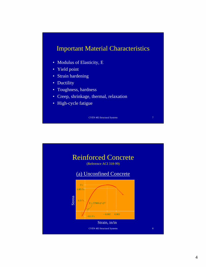
Important Material Characteristics
• Modulus of Elasticity, E• Yield point• Strain hardening• Ductility• Toughness, hardness• Creep, shrinkage, thermal, relaxation• High-cycle fatigue
CVEN 483 Structural Systems 8
Reinforced Concrete(Reference ACI 318-99)
(a) Unconfined Concrete
0.003~ 0.002
0.3 f’c
0.85 f’c
f’c
~0.1 f’c
E = 57000 (f’c)0.5
Strain, in/in
Stre
ss

5
CVEN 483 Structural Systems 9
Reinforced Concrete(Reference ACI 318-99)
(a) Confined Concrete
0.003 ~> 0.03
f’c
f’cc
Strain, in/in
Stre
ss
CVEN 483 Structural Systems 10
Reinforced Concrete(Reference ACI 318-99)
(b) Normal reinforcing SteelASTM A615,A617 [40,60 ksi]
(c) Prestressing bars & strands - A421,A416 [250,
270 ksi]
~0.002 ~ 0.16
fu
Strain, in/in
Stre
ss fy
~ 0.04
fpu
Strain, in/in
Stre
ss
fpy

6
CVEN 483 Structural Systems 11
Structural Steel(Reference AISC-LRFD 1998 or AISC-ASD 19??)
• ASTM A36, 572, 615
~0.002 ~ 0.16
Strain, in/in
Stre
ss
CVEN 483 Structural Systems 12
Reinforced Masonry(Reference ACI 530-99/ASCE 5-99/TMS 402-99)
• ASTM C34, C56, C62, C126 (Clay or Shale)• ASTM C55, C73, C90, C129, C744 (Concrete)
0.33 f’m
f’m
Em = 700-900 f’m
Strain, in/in
Stre
ss

7
CVEN 483 Structural Systems 13
Wood(Reference NDS 1997)
• Historical design approach was based on allowable stresses (ASD). LRFD approach is currently available.
• Many grades of wood – Southern Pine dominant in TX• Many types of failure mechanism, ie. various forms of
crushing and splitting (parallel or perpendicular to the grain)
• Bolted/nailed connections • Plywood – bonded sheets of wood (improves directionality
properties of wood)
CVEN 483 Structural Systems 14
Aluminum(Reference Metals Handbook)
Advantages:1. High strength/weight ratio2. Minimal maintenance due to stability in most
atmospheric environments 3. Fatigue advantages ??Applications:1. Aircraft

8
CVEN 483 Structural Systems 15
Metal Structures
Advantages:• Warehouse type structures
CVEN 483 Structural Systems 16
Fiber Reinforced Polymers(ACI Committee 440, Trejo et al [2000])
Advantages are realized:• Due to the high strength• Strength/weight ratio• Corrosive resistance• Non-magnetic characteristics
Disadvantages:• High temperatures• Brittle behavior
9
CVEN 483 Structural Systems 17
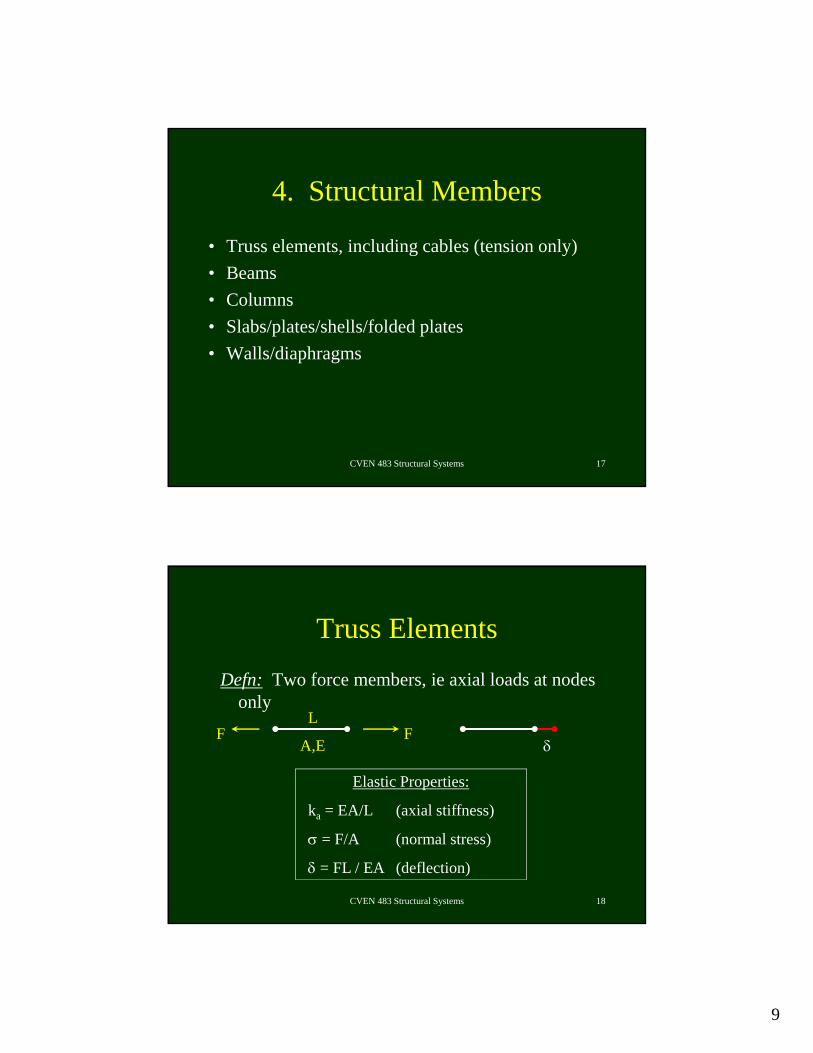
4. Structural Members
• Truss elements, including cables (tension only)• Beams• Columns• Slabs/plates/shells/folded plates• Walls/diaphragms
CVEN 483 Structural Systems 18
Truss ElementsDefn: Two force members, ie axial loads at nodes
only
F FL
A,E
Elastic Properties:
ka = EA/L (axial stiffness)
σ = F/A (normal stress)
δ = FL / EA (deflection)
δ
10
CVEN 483 Structural Systems 19
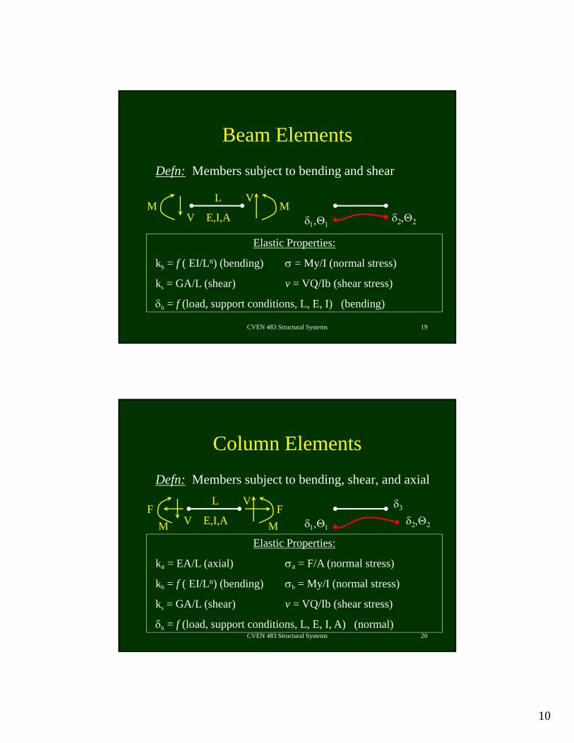
Beam ElementsDefn: Members subject to bending and shear
Elastic Properties:
kb = f ( EI/Ln) (bending) σ = My/I (normal stress)
ks = GA/L (shear) v = VQ/Ib (shear stress)
δb = f (load, support conditions, L, E, I) (bending)
V
VL
E,I,AMM
δ2,Θ2δ1,Θ1
CVEN 483 Structural Systems 20
Column ElementsDefn: Members subject to bending, shear, and axial
Elastic Properties:
ka = EA/L (axial) σa = F/A (normal stress)
kb = f ( EI/Ln) (bending) σb = My/I (normal stress)
ks = GA/L (shear) v = VQ/Ib (shear stress)
δb = f (load, support conditions, L, E, I, A) (normal)
V
VL
E,I,A MMF F
δ2,Θ2δ1,Θ1
δ3

11
CVEN 483 Structural Systems 21
Slab/Plate ElementsDefn: Members subject to bi-directional bending & shear
x
yz
Mx, My, and Vz
Θx, Θy, and δz
CVEN 483 Structural Systems 22
Wall/Diaphragm ElementsDefn: Members subject to shear
x
y
Vx and Vy
δx and δy

12
CVEN 483 Structural Systems 23
5. Structural Systems
Gravity:• Trusses• Frames• Walls• Dual systems• Plates
Lateral:• Trusses• Frames• Braced Frames• Walls• Dual systems• Diaphragms
CVEN 483 Structural Systems 24
Truss: Coplanar system of truss elements governed by axial deformations
Planar (2D) Space (3D)

13
CVEN 483 Structural Systems 25
Basic Truss Unit
Stable Unstable
CVEN 483 Structural Systems 26
Truss Types

14
CVEN 483 Structural Systems 27
Truss Behavior
• Act as long, deep beams with cutout webs• Resistance increases when upper and lower chords
are spaced further apart. Bottom, corner elements are critical
CVEN 483 Structural Systems 28
Truss Connections
• Modeled as pinned• Gusset plates used to connect members at
nodal points• Riveted (past practice), high strength bolt,
or welded connections

15
CVEN 483 Structural Systems 29
Truss Advantages
• Optimum use of material properties (entire section acts in tension or compression)
• Optimal for high strength, lightweight materials, ie steel, aluminum, FRP
• Ideal for long spans, ie. roofs and bridges• Constructability is efficient, ie. build on ground or
in fab shop and lift into place
CVEN 483 Structural Systems 30
Truss Disadvantages
• Requires significant total depth, which increases nonstructural cladding.
• With long spans, vibrations tend to be a problem in terms of both magnitude and frequency of vibration.

16
CVEN 483 Structural Systems 31
Steel Bar Joists
• Steel bar joists can be economical in some buildings, ie. roofs and floors in any Walmart, sporting complex, or newer office buildings
CVEN 483 Structural Systems 32
Frame SystemsIBC 2000
• Building Frame– Complete space frame systems providing support for gravity loads
and seismic resistance is provided by shear walls or braced frames
• Dual Frame– Complete space frame systems providing support for gravity loads
and seismic resistance is provided by the space frame and shear walls or braced frames
• Space Frame– Members that are capable of supporting gravity loads and also
provide resistance to seismic forces

17
CVEN 483 Structural Systems 33
Moment Frame SystemsIBC 2000
• Ordinary (OMF)– Members and joints are capable of resisting forces by flexure as
well as along the member axis
• Intermediate (IMF)– Members and joints are capable of resisting forces by flexure as
well as along the member axis with some extra detailing requirements for ductility
• Special (SMF)– Members and joints are capable of resisting forces by flexure as
well as along the member axis with special detailing requirement for ductility
CVEN 483 Structural Systems 34
Frame: Coplanar system of beam and column elements dominated by flexural deformation
Planar (2D) Space (3D)

18
CVEN 483 Structural Systems 35
Basic Behavior
Gravity Load Lateral Loading
CVEN 483 Structural Systems 36
2D vs. 3D Frames (Plan)
Planar Space
Gravity Frame Lateral Frame

19
CVEN 483 Structural Systems 37
Frame Advantages
• Optimum use of floor space, ie. optimal for office bldgs, retail, parking structures where open space is required.
• Relatively simple and experienced construction process• Generally economical for low-to mid-rise construction
(less than about 20 stories)• In Houston, most frames are made of reinforced concrete.
CVEN 483 Structural Systems 38
Frame Disadvantages
• Generally, frames are flexible structures and lateral deflections generally control the design process for buildings with greater than about 4 stories. Note that concrete frame are about 8 times stiffer than steel frames of the same strength.
• Span lengths are limited with using normal reinforced concrete (generally less than about 40 ft, but up to about 50 ft). Span lengths can be increased by using prestressed concrete.

20
CVEN 483 Structural Systems 39
Frame Lateral Load SystemsFlat plate-column frame:
Plan Elevation
Effective slab width
CVEN 483 Structural Systems 40
Frame Lateral Load SystemsBeam-column frame:
Elevation
21
CVEN 483 Structural Systems 41
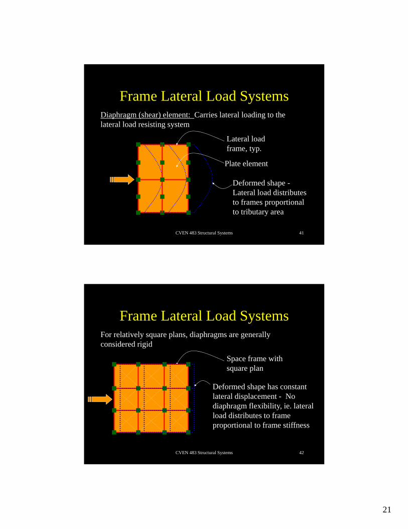
Frame Lateral Load SystemsDiaphragm (shear) element: Carries lateral loading to the lateral load resisting system
Lateral load frame, typ.
Plate element
Deformed shape -Lateral load distributes to frames proportional to tributary area
CVEN 483 Structural Systems 42
Frame Lateral Load SystemsFor relatively square plans, diaphragms are generally considered rigid
Space frame with square plan
Deformed shape has constant lateral displacement - No diaphragm flexibility, ie. lateral load distributes to frame proportional to frame stiffness

22
CVEN 483 Structural Systems 43
Braced Frame: Coplanar system of beam and column elements dominated by flexural deformation and truss elements dominated by axial deformation
Planar (2D) Space (3D)
CVEN 483 Structural Systems 44
Braced FramesConcentric
Elevation
Eccentric
Link elements
Truss elements
Elevation

23
CVEN 483 Structural Systems 45
Concentrically Braced FramesBeam-column frame:
ElevationNote: Deformations are a function of axial stiffness in truss elements
CVEN 483 Structural Systems 46
Eccentrically Braced FramesBeam-column frame:
ElevationNote: Deformations are a function of shear stiffness in link elements

24
CVEN 483 Structural Systems 47
Frame Lateral Load SystemsDiaphragm (shear) element: Carries lateral loading to the lateral load resisting system
Lateral load frame, typ.
Plate element
Deformed shape -Lateral load distributes to frames proportional to tributary area
CVEN 483 Structural Systems 48
Braced Frame Advantages
• Much stiffer and stronger lateral load system when compared with frame systems
• Optimum use of floor space. Most braced frames are on the building perimeter or near elevator stairwell
• Generally economical for low-rise construction (less than about 5 stories)
• Eccentricity braced frames have superior seismic resistance due to very ductile link elements (fuses)

25
CVEN 483 Structural Systems 49
Frame Disadvantages
• Architectural constraints. Sometimes braces must be hidden and other times can be visualized as part of the architectural scheme.
CVEN 483 Structural Systems 50
Shear Wall Lateral Load SystemsShear wall
Elevation
Edge column
Interior gravity frames
Shear deformations generally govern

26
CVEN 483 Structural Systems 51
Shear Wall Lateral Load Systems
Gravity frames
Shear walls
Coupling beams
Elevator shaft configuration
Hole
CVEN 483 Structural Systems 52
Dual Lateral Load Systems
Lateral frames –25% of lateral load, minimum
Shear walls
Wall-Frame Dual System:
Hole

27
CVEN 483 Structural Systems 53
Non-Structural System
• Cladding – concrete, masonry, glass, etc• Electrical, mechanical, HVAC, etc.• Ceilings, partition walls, book cases, filing cabinets,
elevated computer floors, etc.
CVEN 483 Structural Systems 54
Floor Diaphragm Flexibility
• Can be a concern with exterior braced frames or shear wall systems that have a rectangular floor plan
• Special design considerations must be followed• According to IBC 2000, lateral forces get distributed to the
lateral force resisting system– Proportional to the frame stiffness for rigid diaphragms– Proportional to the tributary mass that each frame carries for
flexible diaphragms