cv1 - New Creations · 2 NKBA: Kitchen & Bathroom National Kitchen & Bath Association 687 Willow...
68
cv1 Planning Guidelines with Access Standards
Transcript of cv1 - New Creations · 2 NKBA: Kitchen & Bathroom National Kitchen & Bath Association 687 Willow...
cv1Planning Guidelines with Access Standards

Kitchen & Bathroom
Planning Guidelines
with Access Standards
1
2 NKBA: Kitchen & Bathroom
National Kitchen & Bath Association687 Willow Grove StreetHackettstown, NJ 07840Phone: 800-THE-NKBA (800-843-6522) Fax: 908-852-1695Website: www.NKBA.org
Printed in the United States of America
Updated January 2010
Copyright © 2010 National Kitchen & Bath Association. All rights reserved.No part of this publication may be reproduced or transmitted in any form or by any means, electronic or mechanical, including photocopying, recording, or by an information storage and retrieval system, without the written permission of the publisher.
Disclaimer
The NKBA Kitchen & Bathroom Planning Guidelines with Access Standards has been prepared to assist kitchen
and bath designers and installers in the space planning of kitchens and baths. Anyone designing kitchen or bath
plans or installing kitchen and bath products has an independent obligation to ascertain that their plans, actions,
and practices represent sound business practices for their design and installation and meet all relevant laws,
codes, and standards.
Designers and installers should vary their approach with respect to particular installations, products, or locations
based on specific factual circumstances, the practicality and effectiveness of the particular design or installation,
or its technical feasibility. These guidelines are not designed or intended to define or create legal rights or
obligations. Any recommendation, express or implied, is for illustrative purposes, and is not intended to be
an endorsement of any particular product or manufacturer.
The National Kitchen & Bath Association does not make any warranty or representation, either express or implied,
with respect to the accuracy or completeness of the information contained in the planning guidelines; nor does
the National Kitchen & Bath Association assume any liability of any kind whatsoever resulting from the use of or
reliance upon any information, conclusions, or opinions contained herein.
The NKBA
The National Kitchen & Bath Association (NKBA) is a leading non-profit trade association dedicated to the advancement of the kitchen & bath industry. The NKBA has maintained its leadership status of excel-lence and professionalism for 45 years by providing education, certification, and the tools needed for suc-cess. NKBA Education and Certification are the gold standard in the kitchen & bath industry. The NKBA offers professional development courses and levels of certification for all stages of an individual’s career.
NKBA Education:
NKBA Professional Development provides kitchen and bath professionals convenient and premier educa-tional courses that will enhance their careers. The NKBA provides focused, in-person professional develop-ment training and unique networking opportunities at more than 45 locations across North America, as well as educational opportunities through seminars, webinars, e-learning, online courses, web series, and conferences. Professional development courses are aligned to specific industry segments such as dealers, cabinet shops, fabricators, and installers. Industry pro-fessionals can quickly determine which courses are ap-propriate for their segments by accessing the course descriptions on the NKBA website at www.nkba.org, as well as in the NKBA Education Brochure. Finally, the NKBA has more than 50 Supported and Accredited Programs in colleges and universities across North America that specialize in kitchen and bath design.
NKBA Certification:
NKBA Certification is based on in-depth testing and extensive industry experience, allowing consumers to know that their designers’ professional skills have been independently evaluated and tested. NKBA-certified professionals are committed to improving those skills through meeting continuing education and professional development requirements.
There are three levels of NKBA Certification for de-signers: Associate Kitchen & Bath Designer (AKBD®), Certified Kitchen Designer (CKD®) or Certified Bath Designer (CBD®), and Certified Master Kitchen & Bath Designer (CMKBD®). In addition, the NKBA offers edu-cation and testing to enable an experienced installer to become a Certified Kitchen & Bath Installer (CKBI®).
3Planning Guidelines with Access Standards
4
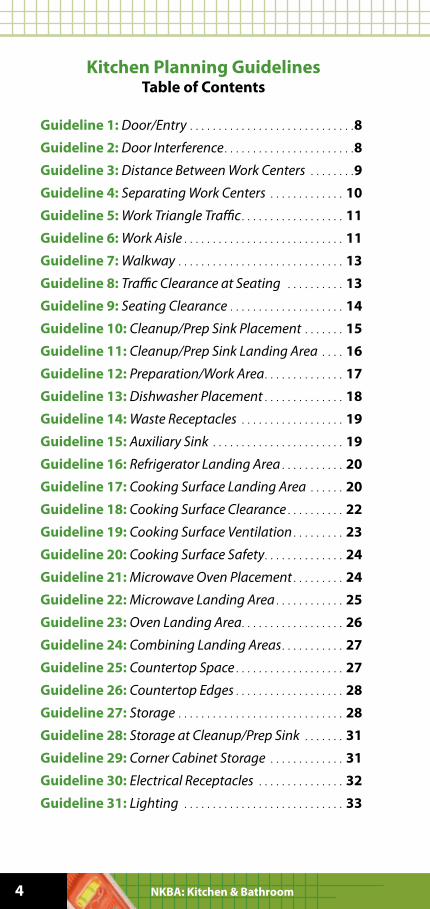
Kitchen Planning Guidelines Table of Contents
Guideline 1: Door/Entry . . . . . . . . . . . . . . . . . . . . . . . . . . . . .8
Guideline 2: Door Interference . . . . . . . . . . . . . . . . . . . . . . .8
Guideline 3: Distance Between Work Centers . . . . . . . .9
Guideline 4: Separating Work Centers . . . . . . . . . . . . . 10
Guideline 5: Work Triangle Traffic . . . . . . . . . . . . . . . . . . 11
Guideline 6: Work Aisle . . . . . . . . . . . . . . . . . . . . . . . . . . . . 11
Guideline 7: Walkway . . . . . . . . . . . . . . . . . . . . . . . . . . . . . 13
Guideline 8: Traffic Clearance at Seating . . . . . . . . . . 13
Guideline 9: Seating Clearance . . . . . . . . . . . . . . . . . . . . 14
Guideline 10: Cleanup/Prep Sink Placement . . . . . . . 15
Guideline 11: Cleanup/Prep Sink Landing Area . . . . 16
Guideline 12: Preparation/Work Area . . . . . . . . . . . . . . 17
Guideline 13: Dishwasher Placement . . . . . . . . . . . . . . 18
Guideline 14: Waste Receptacles . . . . . . . . . . . . . . . . . . 19
Guideline 15: Auxiliary Sink . . . . . . . . . . . . . . . . . . . . . . . 19
Guideline 16: Refrigerator Landing Area . . . . . . . . . . . 20
Guideline 17: Cooking Surface Landing Area . . . . . . 20
Guideline 18: Cooking Surface Clearance . . . . . . . . . . 22
Guideline 19: Cooking Surface Ventilation . . . . . . . . . 23
Guideline 20: Cooking Surface Safety . . . . . . . . . . . . . . 24
Guideline 21: Microwave Oven Placement . . . . . . . . . 24
Guideline 22: Microwave Landing Area . . . . . . . . . . . . 25
Guideline 23: Oven Landing Area. . . . . . . . . . . . . . . . . . 26
Guideline 24: Combining Landing Areas . . . . . . . . . . . 27
Guideline 25: Countertop Space . . . . . . . . . . . . . . . . . . . 27
Guideline 26: Countertop Edges . . . . . . . . . . . . . . . . . . . 28
Guideline 27: Storage . . . . . . . . . . . . . . . . . . . . . . . . . . . . . 28
Guideline 28: Storage at Cleanup/Prep Sink . . . . . . . 31
Guideline 29: Corner Cabinet Storage . . . . . . . . . . . . . 31
Guideline 30: Electrical Receptacles . . . . . . . . . . . . . . . 32
Guideline 31: Lighting . . . . . . . . . . . . . . . . . . . . . . . . . . . . 33
NKBA: Kitchen & Bathroom
5Planning Guidelines with Access Standards
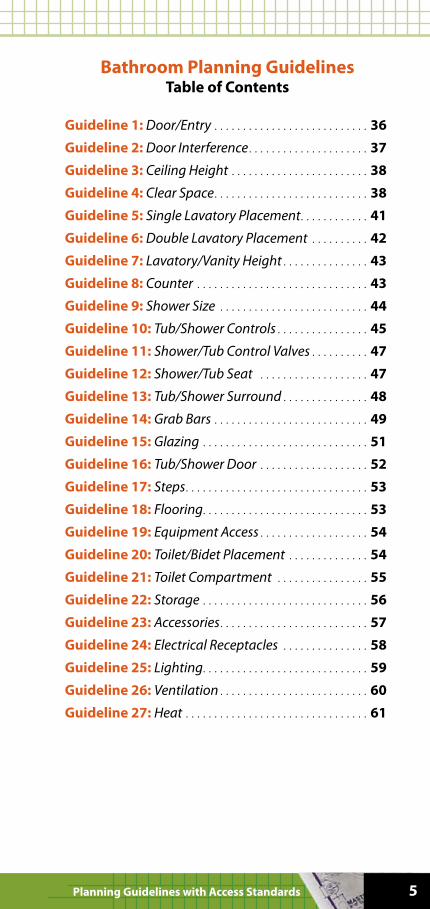
Bathroom Planning Guidelines Table of Contents
Guideline 1: Door/Entry . . . . . . . . . . . . . . . . . . . . . . . . . . . 36
Guideline 2: Door Interference . . . . . . . . . . . . . . . . . . . . . 37
Guideline 3: Ceiling Height . . . . . . . . . . . . . . . . . . . . . . . . 38
Guideline 4: Clear Space . . . . . . . . . . . . . . . . . . . . . . . . . . . 38
Guideline 5: Single Lavatory Placement . . . . . . . . . . . . 41
Guideline 6: Double Lavatory Placement . . . . . . . . . . 42
Guideline 7: Lavatory/Vanity Height . . . . . . . . . . . . . . . 43
Guideline 8: Counter . . . . . . . . . . . . . . . . . . . . . . . . . . . . . . 43
Guideline 9: Shower Size . . . . . . . . . . . . . . . . . . . . . . . . . . 44
Guideline 10: Tub/Shower Controls . . . . . . . . . . . . . . . . 45
Guideline 11: Shower/Tub Control Valves . . . . . . . . . . 47
Guideline 12: Shower/Tub Seat . . . . . . . . . . . . . . . . . . . 47
Guideline 13: Tub/Shower Surround . . . . . . . . . . . . . . . 48
Guideline 14: Grab Bars . . . . . . . . . . . . . . . . . . . . . . . . . . . 49
Guideline 15: Glazing . . . . . . . . . . . . . . . . . . . . . . . . . . . . . 51
Guideline 16: Tub/Shower Door . . . . . . . . . . . . . . . . . . . 52
Guideline 17: Steps . . . . . . . . . . . . . . . . . . . . . . . . . . . . . . . . 53
Guideline 18: Flooring. . . . . . . . . . . . . . . . . . . . . . . . . . . . . 53
Guideline 19: Equipment Access . . . . . . . . . . . . . . . . . . . 54
Guideline 20: Toilet/Bidet Placement . . . . . . . . . . . . . . 54
Guideline 21: Toilet Compartment . . . . . . . . . . . . . . . . 55
Guideline 22: Storage . . . . . . . . . . . . . . . . . . . . . . . . . . . . . 56
Guideline 23: Accessories . . . . . . . . . . . . . . . . . . . . . . . . . . 57
Guideline 24: Electrical Receptacles . . . . . . . . . . . . . . . 58
Guideline 25: Lighting. . . . . . . . . . . . . . . . . . . . . . . . . . . . . 59
Guideline 26: Ventilation . . . . . . . . . . . . . . . . . . . . . . . . . . 60
Guideline 27: Heat . . . . . . . . . . . . . . . . . . . . . . . . . . . . . . . . 61
6
Methodology/Overview:
The NKBA Kitchen & Bathroom Planning Guidelines with Access Standards is a collection of illustrations and planning suggestions to aid professionals in the safe and effective planning of kitchens and bath-rooms. These guidelines are excerpted from the National Kitchen & Bath Association Professional Resource Library Kitchen Planning and Bath Planning volumes. Designers and those interested in becom-ing kitchen and bath design professionals benefit by studying the complete body of knowledge found in the NKBA Professional Resource Library.
These flexible and easy-to-understand guidelines were developed under the guidance of the NKBA by a committee of professionals. The committee completed in-depth historical reviews of planning guidelines dating back to 1920. The guidelines published in this booklet reflect a composite of the historical review, current industry environment, future trends, consumer lifestyles, new research, new building codes, and current industry practices, as well as a Kitchen Storage Research Project con-ducted by Virginia Polytechnic Institute.
The purpose of the guidelines is to serve as the basis for: • Testing core kitchen and bath design
competencies • Critiquing designer work • Training designers in academic and
educational programs • Recognizing the importance of consumer health,
safety, and welfare in kitchen and bath design
NKBA: Kitchen & Bathroom
7Planning Guidelines with Access Standards
Kitchen Planning Guidelines with Access Standards
The National Kitchen & Bath Association
developed the Kitchen Planning Guidelines
with Access Standards to provide designers
with good planning practices that consider
the needs of a range of users.
The code references for the Kitchen Planning
Guidelines are based on the analysis of the
2006 International Residential Code (IRC) and
the International Plumbing Code.
The code references for the Access Standards
are based on ICC/ANSI 117.1 – 2003 Accessible
and Useable Buildings and Facilities.
Be sure to check local, state, and national laws
that apply to your design and follow those
legal requirements.
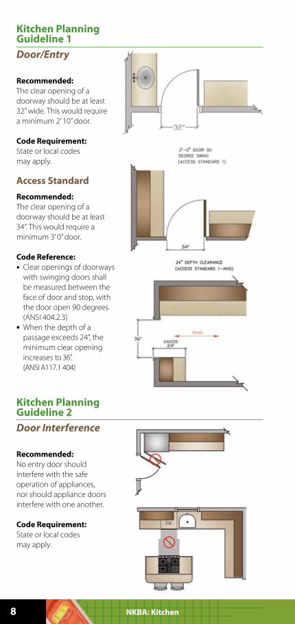
Kitchen Planning Guideline 1
Door/Entry
Recommended:
The clear opening of a
doorway should be at least
32’’ wide. This would require
a minimum 2’ 10’’ door.
Code Requirement:
State or local codes
may apply.
Access Standard
Recommended:
The clear opening of a
doorway should be at least
34’’. This would require a
minimum 3’ 0’’ door.
Code Reference:
• Clear openings of doorways
with swinging doors shall
be measured between the
face of door and stop, with
the door open 90 degrees.
(ANSI 404.2.3)
• When the depth of a
passage exceeds 24”, the
minimum clear opening
increases to 36”.
(ANSI A117.1 404)
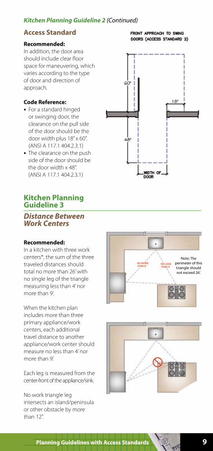
Kitchen Planning Guideline 2
Door Interference
Recommended:
No entry door should
interfere with the safe
operation of appliances,
nor should appliance doors
interfere with one another.
Code Requirement:
State or local codes
may apply.
8 NKBA: Kitchen
9Planning Guidelines with Access Standards
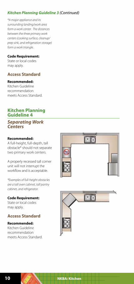
Access Standard
Recommended:
In addition, the door area
should include clear floor
space for maneuvering, which
varies according to the type
of door and direction of
approach.
Code Reference:
• For a standard hinged
or swinging door, the
clearance on the pull side
of the door should be the
door width plus 18” x 60”.
(ANSI A 117.1 404.2.3.1)
• The clearance on the push
side of the door should be
the door width x 48”.
(ANSI A 117.1 404.2.3.1)
Kitchen Planning Guideline 2 (Continued)
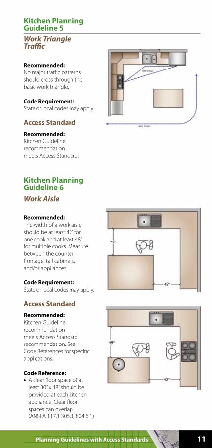
Kitchen Planning Guideline 3
Distance Between Work Centers
Recommended:
In a kitchen with three work
centers*, the sum of the three
traveled distances should
total no more than 26’ with
no single leg of the triangle
measuring less than 4’ nor
more than 9’.
When the kitchen plan
includes more than three
primary appliance/work
centers, each additional
travel distance to another
appliance/work center should
measure no less than 4’ nor
more than 9’.
Each leg is measured from the
center-front of the appliance/sink.
No work triangle leg
intersects an island/peninsula
or other obstacle by more
than 12”.
Note: The
perimeter of this
triangle should
not exceed 26’.
10 NKBA: Kitchen
*A major appliance and its
surrounding landing/work area
form a work center. The distances
between the three primary work
centers (cooking surface, cleanup/
prep sink, and refrigeration storage)
form a work triangle.
Code Requirement:
State or local codes
may apply.
Access Standard
Recommended:
Kitchen Guideline
recommendation
meets Access Standard.
Kitchen Planning Guideline 3 (Continued)
Kitchen Planning Guideline 4
Separating Work Centers
Recommended:
A full-height, full-depth, tall
obstacle* should not separate
two primary work centers.
A properly recessed tall corner
unit will not interrupt the
workflow and is acceptable.
*Examples of full-height obstacles
are a tall oven cabinet, tall pantry
cabinet, and refrigerator.
Code Requirement:
State or local codes
may apply.
Access Standard
Recommended:
Kitchen Guideline
recommendation
meets Access Standard.
11Planning Guidelines with Access Standards
Kitchen Planning Guideline 5
Work Triangle Traffic
Recommended:
No major traffic patterns
should cross through the
basic work triangle.
Code Requirement:
State or local codes may apply.
Access Standard
Recommended:
Kitchen Guideline
recommendation
meets Access Standard.
Kitchen Planning Guideline 6
Work Aisle
Recommended:
The width of a work aisle
should be at least 42” for
one cook and at least 48”
for multiple cooks. Measure
between the counter
frontage, tall cabinets,
and/or appliances.
Code Requirement:
State or local codes may apply.
Access Standard
Recommended:
Kitchen Guideline
recommendation
meets Access Standard
recommendation. See
Code References for specific
applications.
Code Reference:
• A clear floor space of at
least 30” x 48” should be
provided at each kitchen
appliance. Clear floor
spaces can overlap.
(ANSI A 117.1 305.3, 804.6.1)
12 NKBA: Kitchen
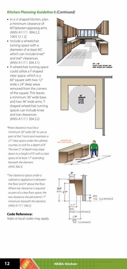
• In a U-shaped kitchen, plan
a minimum clearance of
60” between opposing arms.
(ANSI A117.1 804.2.2,
1003.12.1.2)
• Include a wheelchair
turning space with a
diameter of at least 60”,
which can include knee*
and toe* clearances.
(ANSI A117.1 304.3.1)
• A wheelchair turning space
could utilize a T-shaped
clear space, which is a
60” square with two 12”
wide x 24” deep areas
removed from the corners
of the square. This leaves
a minimum 36” wide base
and two 36” wide arms. T-
shaped wheelchair turning
spaces can include knee
and toe clearances.
(ANSI A117.1 304.3.2)
* Knee clearance must be a
minimum 30” wide (36” to use as
part of the T-turn) and maintain a
27” clear space under the cabinet,
counter, or sink for a depth of 8”.
The next 3” of depth may slope
down to a height of 9”, with a clear
space of at least 17” extending
beneath the element.
(ANSI 306.3)
* Toe clearance space under a
cabinet or appliance is between
the floor and 9” above the floor.
Where toe clearance is required
as part of a clear floor space, the
toe clearance should extend 17”
minimum beneath the element.
(ANSI A117.1 306.2)
Code Reference:
State or local codes may apply.
Kitchen Planning Guideline 6 (Continued)
13Planning Guidelines with Access Standards
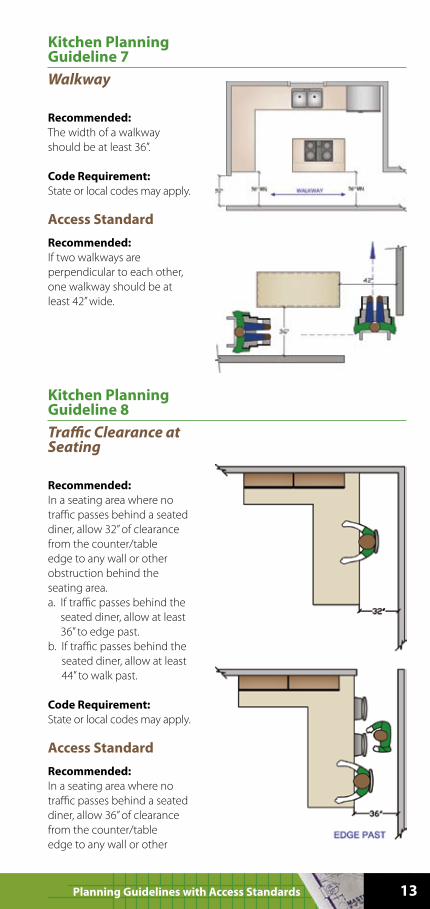
Kitchen Planning Guideline 7
Walkway
Recommended:
The width of a walkway
should be at least 36”.
Code Requirement:
State or local codes may apply.
Access Standard
Recommended:
If two walkways are
perpendicular to each other,
one walkway should be at
least 42” wide.
Kitchen Planning Guideline 8
Traffic Clearance at Seating
Recommended:
In a seating area where no
traffic passes behind a seated
diner, allow 32” of clearance
from the counter/table
edge to any wall or other
obstruction behind the
seating area.
a. If traffic passes behind the
seated diner, allow at least
36” to edge past.
b. If traffic passes behind the
seated diner, allow at least
44” to walk past.
Code Requirement:
State or local codes may apply.
Access Standard
Recommended:
In a seating area where no
traffic passes behind a seated
diner, allow 36” of clearance
from the counter/table
edge to any wall or other
14 NKBA: Kitchen
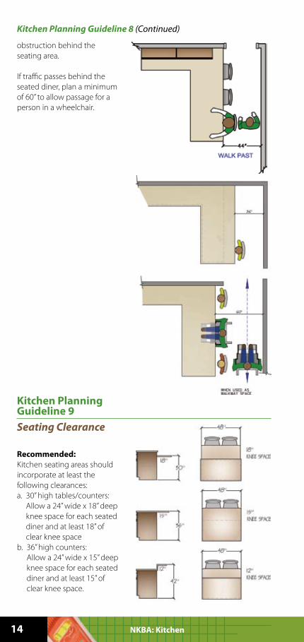
obstruction behind the
seating area.
If traffic passes behind the
seated diner, plan a minimum
of 60” to allow passage for a
person in a wheelchair.
Kitchen Planning Guideline 8 (Continued)
Kitchen Planning Guideline 9
Seating Clearance
Recommended:
Kitchen seating areas should
incorporate at least the
following clearances:
a. 30” high tables/counters:
Allow a 24” wide x 18” deep
knee space for each seated
diner and at least 18” of
clear knee space
b. 36” high counters:
Allow a 24” wide x 15” deep
knee space for each seated
diner and at least 15” of
clear knee space.
15Planning Guidelines with Access Standards
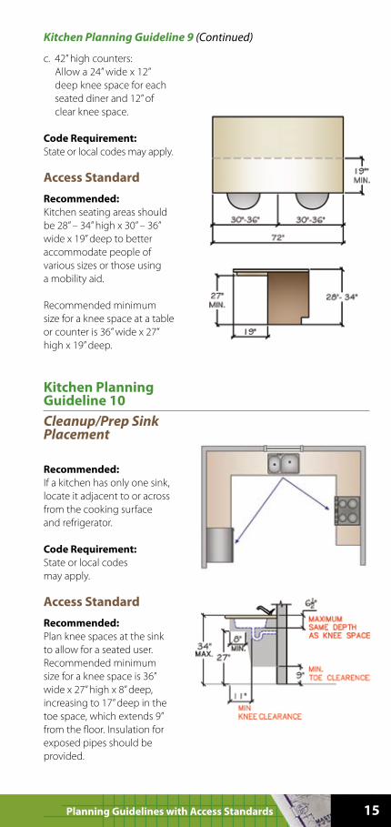
c. 42” high counters:
Allow a 24” wide x 12”
deep knee space for each
seated diner and 12” of
clear knee space.
Code Requirement:
State or local codes may apply.
Access Standard
Recommended:
Kitchen seating areas should
be 28” – 34” high x 30” – 36”
wide x 19” deep to better
accommodate people of
various sizes or those using
a mobility aid.
Recommended minimum
size for a knee space at a table
or counter is 36” wide x 27”
high x 19” deep.
Kitchen Planning Guideline 9 (Continued)
Kitchen Planning Guideline 10
Cleanup/Prep Sink Placement
Recommended:
If a kitchen has only one sink,
locate it adjacent to or across
from the cooking surface
and refrigerator.
Code Requirement:
State or local codes
may apply.
Access Standard
Recommended:
Plan knee spaces at the sink
to allow for a seated user.
Recommended minimum
size for a knee space is 36”
wide x 27” high x 8” deep,
increasing to 17” deep in the
toe space, which extends 9”
from the floor. Insulation for
exposed pipes should be
provided.
16 NKBA: Kitchen
Code Reference:
• The sink should be no more
than 34” high or adjustable
between 29” and 36”.
(ANSI 117.1.1002.4.2)
• The sink bowl should be no
more than 6 1/2” deep.
(ANSI 117.1 1002.12.4.3)
• Exposed water supply and
drainpipes under sinks
should be insulated or
otherwise configured to
protect against contact.
There should be no sharp or
abrasive surfaces under sinks.
(ANSI A117.1 606.6)
Kitchen Planning Guideline 10 (Continued)
Kitchen Planning Guideline 11
Cleanup/Prep Sink Landing Area
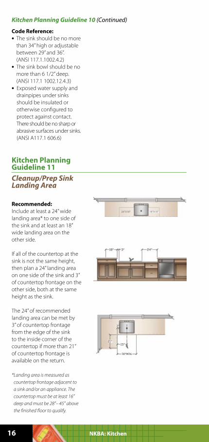
Recommended:
Include at least a 24” wide
landing area* to one side of
the sink and at least an 18”
wide landing area on the
other side.
If all of the countertop at the
sink is not the same height,
then plan a 24” landing area
on one side of the sink and 3”
of countertop frontage on the
other side, both at the same
height as the sink.
The 24” of recommended
landing area can be met by
3” of countertop frontage
from the edge of the sink
to the inside corner of the
countertop if more than 21”
of countertop frontage is
available on the return.
* Landing area is measured as
countertop frontage adjacent to
a sink and/or an appliance. The
countertop must be at least 16”
deep and must be 28”– 45” above
the finished floor to qualify.
17Planning Guidelines with Access Standards
Code Requirement:
State or local codes
may apply.
Access Standard
Recommended:
Kitchen Guideline
recommendation
meets Access Standard.
Kitchen Planning Guideline 11 (Continued)
Kitchen Planning Guideline 12
Preparation/Work Area
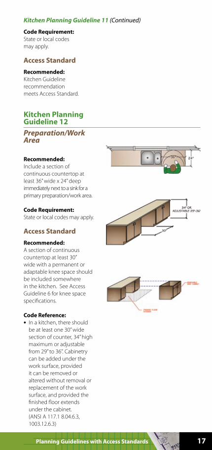
Recommended:
Include a section of
continuous countertop at
least 36” wide x 24” deep
immediately next to a sink for a
primary preparation/work area.
Code Requirement:
State or local codes may apply.
Access Standard
Recommended:
A section of continuous
countertop at least 30”
wide with a permanent or
adaptable knee space should
be included somewhere
in the kitchen. See Access
Guideline 6 for knee space
specifications.
Code Reference:
• In a kitchen, there should
be at least one 30” wide
section of counter, 34” high
maximum or adjustable
from 29” to 36”. Cabinetry
can be added under the
work surface, provided
it can be removed or
altered without removal or
replacement of the work
surface, and provided the
finished floor extends
under the cabinet.
(ANSI A 117.1 8.04.6.3,
1003.12.6.3)
18 NKBA: Kitchen
Kitchen Planning Guideline 13
Dishwasher Placement
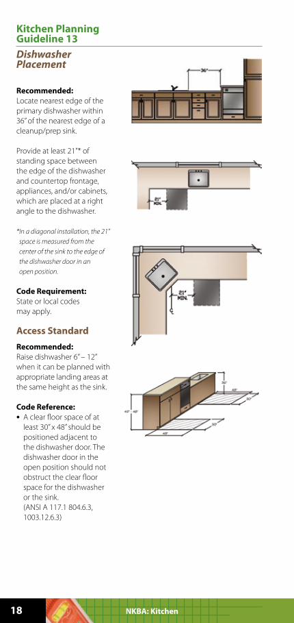
Recommended:
Locate nearest edge of the
primary dishwasher within
36” of the nearest edge of a
cleanup/prep sink.
Provide at least 21”* of
standing space between
the edge of the dishwasher
and countertop frontage,
appliances, and/or cabinets,
which are placed at a right
angle to the dishwasher.
* In a diagonal installation, the 21”
space is measured from the
center of the sink to the edge of
the dishwasher door in an
open position.
Code Requirement:
State or local codes
may apply.
Access Standard
Recommended:
Raise dishwasher 6” – 12”
when it can be planned with
appropriate landing areas at
the same height as the sink.
Code Reference:
• A clear floor space of at
least 30” x 48” should be
positioned adjacent to
the dishwasher door. The
dishwasher door in the
open position should not
obstruct the clear floor
space for the dishwasher
or the sink.
(ANSI A 117.1 804.6.3,
1003.12.6.3)
19Planning Guidelines with Access Standards
Kitchen Planning Guideline 14
Waste Receptacles
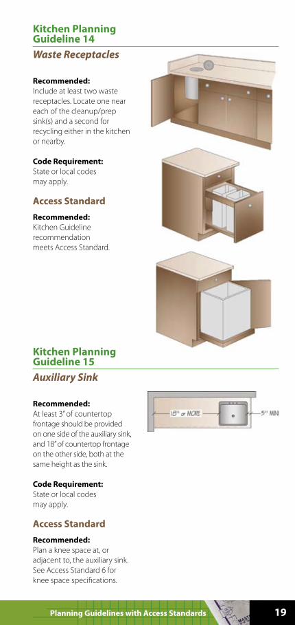
Recommended:
Include at least two waste
receptacles. Locate one near
each of the cleanup/prep
sink(s) and a second for
recycling either in the kitchen
or nearby.
Code Requirement:
State or local codes
may apply.
Access Standard
Recommended:
Kitchen Guideline
recommendation
meets Access Standard.
Kitchen Planning Guideline 15
Auxiliary Sink
Recommended:
At least 3” of countertop
frontage should be provided
on one side of the auxiliary sink,
and 18” of countertop frontage
on the other side, both at the
same height as the sink.
Code Requirement:
State or local codes
may apply.
Access Standard
Recommended:
Plan a knee space at, or
adjacent to, the auxiliary sink.
See Access Standard 6 for
knee space specifications.
20 NKBA: Kitchen
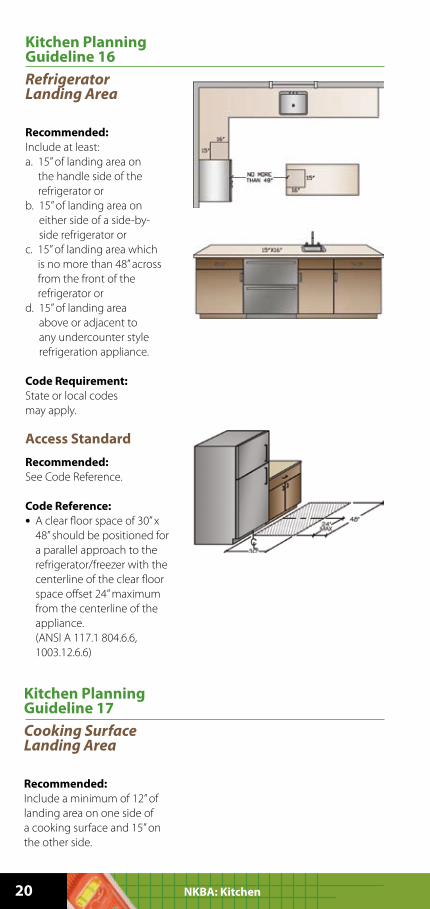
Kitchen Planning Guideline 16
Refrigerator Landing Area
Recommended:
Include at least:
a. 15” of landing area on
the handle side of the
refrigerator or
b. 15” of landing area on
either side of a side-by-
side refrigerator or
c. 15” of landing area which
is no more than 48” across
from the front of the
refrigerator or
d. 15” of landing area
above or adjacent to
any undercounter style
refrigeration appliance.
Code Requirement:
State or local codes
may apply.
Access Standard
Recommended:
See Code Reference.
Code Reference:
• A clear floor space of 30” x
48” should be positioned for
a parallel approach to the
refrigerator/freezer with the
centerline of the clear floor
space offset 24” maximum
from the centerline of the
appliance.
(ANSI A 117.1 804.6.6,
1003.12.6.6)
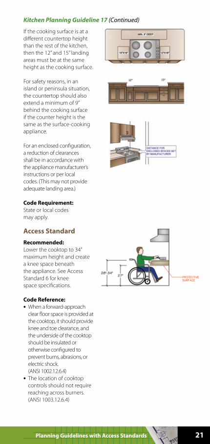
Kitchen Planning Guideline 17
Cooking Surface Landing Area
Recommended:
Include a minimum of 12” of
landing area on one side of
a cooking surface and 15” on
the other side.
21Planning Guidelines with Access Standards
If the cooking surface is at a
different countertop height
than the rest of the kitchen,
then the 12” and 15” landing
areas must be at the same
height as the cooking surface.
For safety reasons, in an
island or peninsula situation,
the countertop should also
extend a minimum of 9”
behind the cooking surface
if the counter height is the
same as the surface-cooking
appliance.
For an enclosed configuration,
a reduction of clearances
shall be in accordance with
the appliance manufacturer’s
instructions or per local
codes. (This may not provide
adequate landing area.)
Code Requirement:
State or local codes
may apply.
Access Standard
Recommended:
Lower the cooktop to 34”
maximum height and create
a knee space beneath
the appliance. See Access
Standard 6 for knee
space specifications.
Code Reference:
• When a forward-approach
clear floor space is provided at
the cooktop, it should provide
knee and toe clearance, and
the underside of the cooktop
should be insulated or
otherwise configured to
prevent burns, abrasions, or
electric shock.
(ANSI 1002.12.6.4)
• The location of cooktop
controls should not require
reaching across burners.
(ANSI 1003.12.6.4)
Kitchen Planning Guideline 17 (Continued)
22 NKBA: Kitchen
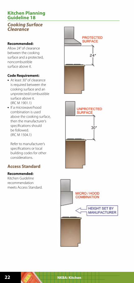
Kitchen Planning Guideline 18
Cooking Surface Clearance
Recommended:
Allow 24” of clearance
between the cooking
surface and a protected,
noncombustible
surface above it.
Code Requirement:
• At least 30” of clearance
is required between the
cooking surface and an
unprotected/combustible
surface above it.
(IRC M 1901.1)
• If a microwave/hood
combination is used
above the cooking surface,
then the manufacturer’s
specifications should
be followed.
(IRC M 1504.1)
Refer to manufacturer’s
specifications or local
building codes for other
considerations.
Access Standard
Recommended:
Kitchen Guideline
recommendation
meets Access Standard.
23Planning Guidelines with Access Standards
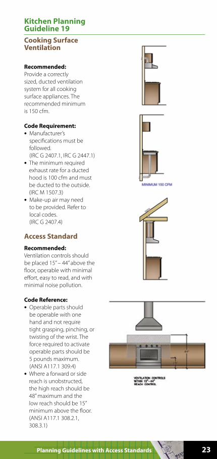
Kitchen Planning Guideline 19
Cooking Surface Ventilation
Recommended:
Provide a correctly
sized, ducted ventilation
system for all cooking
surface appliances. The
recommended minimum
is 150 cfm.
Code Requirement:
• Manufacturer’s
specifications must be
followed.
(IRC G 2407.1, IRC G 2447.1)
• The minimum required
exhaust rate for a ducted
hood is 100 cfm and must
be ducted to the outside.
(IRC M 1507.3)
• Make-up air may need
to be provided. Refer to
local codes.
(IRC G 2407.4)
Access Standard
Recommended:
Ventilation controls should
be placed 15” – 44” above the
floor, operable with minimal
effort, easy to read, and with
minimal noise pollution.
Code Reference:
• Operable parts should
be operable with one
hand and not require
tight grasping, pinching, or
twisting of the wrist. The
force required to activate
operable parts should be
5 pounds maximum.
(ANSI A117.1 309.4)
• Where a forward or side
reach is unobstructed,
the high reach should be
48” maximum and the
low reach should be 15”
minimum above the floor.
(ANSI A117.1 308.2.1,
308.3.1)
24 NKBA: Kitchen
• Where a forward or side
reach is obstructed by a
20” – 25” deep counter,
the high reach should be
44” maximum.
(ANSI A117.1 308.2.2)
Kitchen Planning Guideline 19 (Continued)
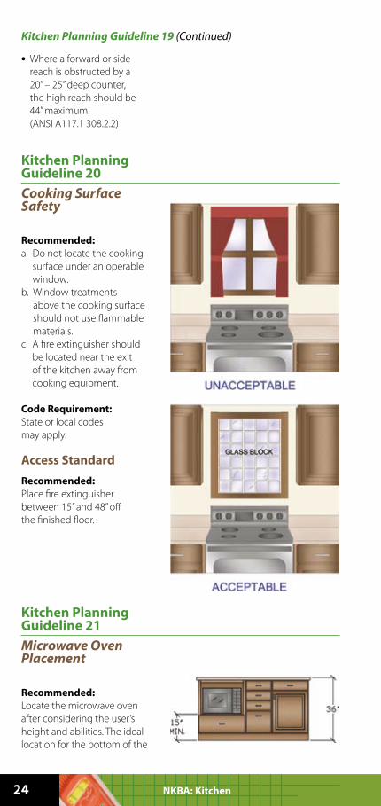
Kitchen Planning Guideline 20
Cooking Surface Safety
Recommended:
a. Do not locate the cooking
surface under an operable
window.
b. Window treatments
above the cooking surface
should not use flammable
materials.
c. A fire extinguisher should
be located near the exit
of the kitchen away from
cooking equipment.
Code Requirement:
State or local codes
may apply.
Access Standard
Recommended:
Place fire extinguisher
between 15” and 48” off
the finished floor.
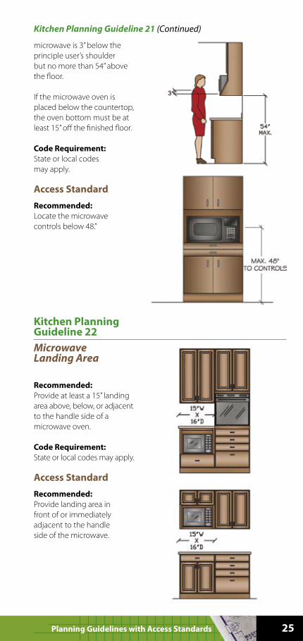
Kitchen Planning Guideline 21
Microwave Oven Placement
Recommended:
Locate the microwave oven
after considering the user’s
height and abilities. The ideal
location for the bottom of the
25Planning Guidelines with Access Standards
Kitchen Planning Guideline 21 (Continued)
microwave is 3” below the
principle user’s shoulder
but no more than 54” above
the floor.
If the microwave oven is
placed below the countertop,
the oven bottom must be at
least 15” off the finished floor.
Code Requirement:
State or local codes
may apply.
Access Standard
Recommended:
Locate the microwave
controls below 48.”
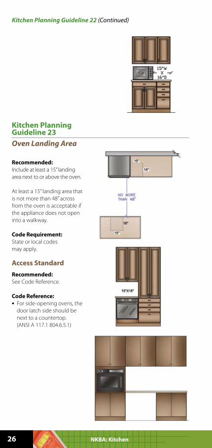
Kitchen Planning Guideline 22
Microwave Landing Area
Recommended:
Provide at least a 15” landing
area above, below, or adjacent
to the handle side of a
microwave oven.
Code Requirement:
State or local codes may apply.
Access Standard
Recommended:
Provide landing area in
front of or immediately
adjacent to the handle
side of the microwave.
26 NKBA: Kitchen
Kitchen Planning Guideline 22 (Continued)
Kitchen Planning Guideline 23
Oven Landing Area
Recommended:
Include at least a 15” landing
area next to or above the oven.
At least a 15” landing area that
is not more than 48” across
from the oven is acceptable if
the appliance does not open
into a walkway.
Code Requirement:
State or local codes
may apply.
Access Standard
Recommended:
See Code Reference.
Code Reference:
• For side-opening ovens, the
door latch side should be
next to a countertop.
(ANSI A 117.1 804.6.5.1)
27Planning Guidelines with Access Standards
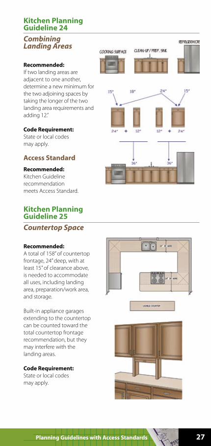
Kitchen Planning Guideline 24
Combining Landing Areas
Recommended:
If two landing areas are
adjacent to one another,
determine a new minimum for
the two adjoining spaces by
taking the longer of the two
landing area requirements and
adding 12.”
Code Requirement:
State or local codes
may apply.
Access Standard
Recommended:
Kitchen Guideline
recommendation
meets Access Standard.
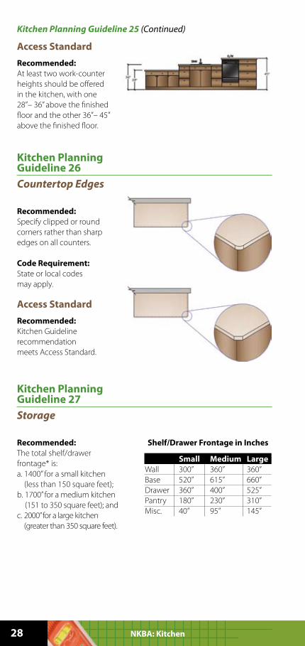
Kitchen Planning Guideline 25
Countertop Space
Recommended:
A total of 158” of countertop
frontage, 24” deep, with at
least 15” of clearance above,
is needed to accommodate
all uses, including landing
area, preparation/work area,
and storage.
Built-in appliance garages
extending to the countertop
can be counted toward the
total countertop frontage
recommendation, but they
may interfere with the
landing areas.
Code Requirement:
State or local codes
may apply.
28 NKBA: Kitchen
Access Standard
Recommended:
At least two work-counter
heights should be offered
in the kitchen, with one
28”– 36” above the finished
floor and the other 36”– 45”
above the finished floor.
Kitchen Planning Guideline 25 (Continued)
Kitchen Planning Guideline 26
Countertop Edges
Recommended:
Specify clipped or round
corners rather than sharp
edges on all counters.
Code Requirement:
State or local codes
may apply.
Access Standard
Recommended:
Kitchen Guideline
recommendation
meets Access Standard.
Kitchen Planning Guideline 27
Storage
Recommended:
The total shelf/drawer
frontage* is:
a. 1400” for a small kitchen
(less than 150 square feet);
b. 1700” for a medium kitchen
(151 to 350 square feet); and
c. 2000” for a large kitchen
(greater than 350 square feet).
Small Medium Large
Wall 300” 360” 360”
Base 520” 615” 660”
Drawer 360” 400” 525”
Pantry 180” 230” 310”
Misc. 40” 95” 145”
Shelf/Drawer Frontage in Inches
29Planning Guidelines with Access Standards
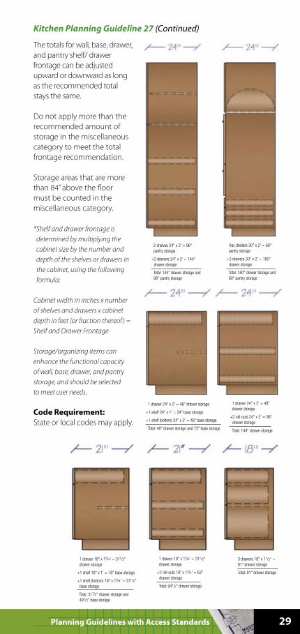
The totals for wall, base, drawer,
and pantry shelf/ drawer
frontage can be adjusted
upward or downward as long
as the recommended total
stays the same.
Do not apply more than the
recommended amount of
storage in the miscellaneous
category to meet the total
frontage recommendation.
Storage areas that are more
than 84” above the floor
must be counted in the
miscellaneous category.
* Shelf and drawer frontage is
determined by multiplying the
cabinet size by the number and
depth of the shelves or drawers in
the cabinet, using the following
formula:
Cabinet width in inches x number
of shelves and drawers x cabinet
depth in feet (or fraction thereof ) =
Shelf and Drawer Frontage
Storage/organizing items can
enhance the functional capacity
of wall, base, drawer, and pantry
storage, and should be selected
to meet user needs.
Code Requirement:
State or local codes may apply.
Kitchen Planning Guideline 27 (Continued)
30 NKBA: Kitchen
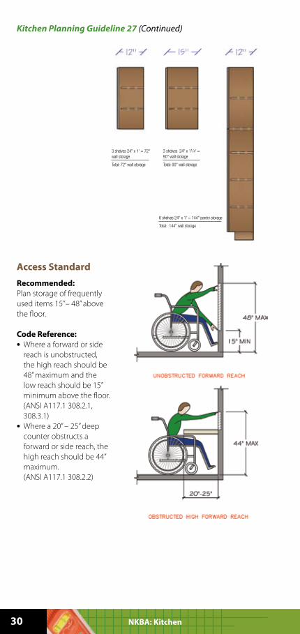
Access Standard
Recommended:
Plan storage of frequently
used items 15”– 48” above
the floor.
Code Reference:
• Where a forward or side
reach is unobstructed,
the high reach should be
48” maximum and the
low reach should be 15”
minimum above the floor.
(ANSI A117.1 308.2.1,
308.3.1)
• Where a 20” – 25” deep
counter obstructs a
forward or side reach, the
high reach should be 44”
maximum.
(ANSI A117.1 308.2.2)
Kitchen Planning Guideline 27 (Continued)
31Planning Guidelines with Access Standards
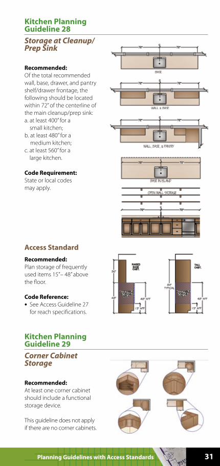
Kitchen Planning Guideline 28
Storage at Cleanup/Prep Sink
Recommended:
Of the total recommended
wall, base, drawer, and pantry
shelf/drawer frontage, the
following should be located
within 72” of the centerline of
the main cleanup/prep sink:
a. at least 400” for a
small kitchen;
b. at least 480” for a
medium kitchen;
c. at least 560” for a
large kitchen.
Code Requirement:
State or local codes
may apply.
Access Standard
Recommended:
Plan storage of frequently
used items 15”– 48” above
the floor.
Code Reference:
• See Access Guideline 27
for reach specifications.
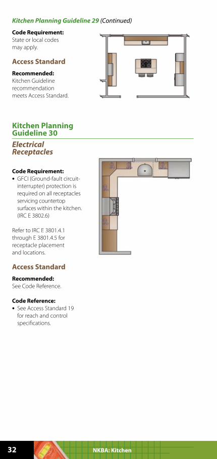
Kitchen Planning Guideline 29
Corner Cabinet Storage
Recommended:
At least one corner cabinet
should include a functional
storage device.
This guideline does not apply
if there are no corner cabinets.
32 NKBA: Kitchen
Code Requirement:
State or local codes
may apply.
Access Standard
Recommended:
Kitchen Guideline
recommendation
meets Access Standard.
Kitchen Planning Guideline 29 (Continued)
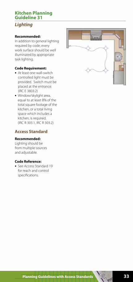
Kitchen Planning Guideline 30
Electrical Receptacles
Code Requirement:
• GFCI (Ground-fault circuit-
interrupter) protection is
required on all receptacles
servicing countertop
surfaces within the kitchen.
(IRC E 3802.6)
Refer to IRC E 3801.4.1
through E 3801.4.5 for
receptacle placement
and locations.
Access Standard
Recommended:
See Code Reference.
Code Reference:
• See Access Standard 19
for reach and control
specifications.
33Planning Guidelines with Access Standards
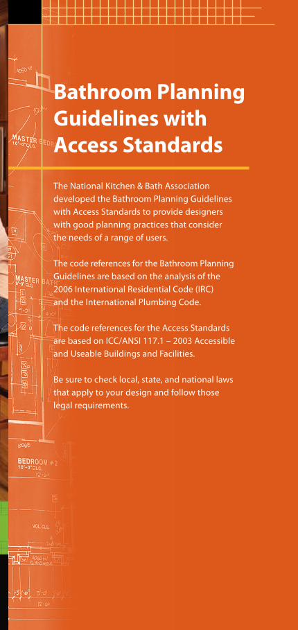
Kitchen Planning Guideline 31
Lighting
Recommended:
In addition to general lighting
required by code, every
work surface should be well
illuminated by appropriate
task lighting.
Code Requirement:
• At least one wall-switch
controlled light must be
provided. Switch must be
placed at the entrance.
(IRC E 3803.2)
• Window/skylight area,
equal to at least 8% of the
total square footage of the
kitchen, or a total living
space which includes a
kitchen, is required.
(IRC R 303.1, IRC R 303.2)
Access Standard
Recommended:
Lighting should be
from multiple sources
and adjustable.
Code Reference:
• See Access Standard 19
for reach and control
specifications.

34 NKBA: Bathroom
Notes:
35Planning Guidelines with Access Standards
Bathroom Planning
Guidelines with
Access Standards
The National Kitchen & Bath Association
developed the Bathroom Planning Guidelines
with Access Standards to provide designers
with good planning practices that consider
the needs of a range of users.
The code references for the Bathroom Planning
Guidelines are based on the analysis of the
2006 International Residential Code (IRC)
and the International Plumbing Code.
The code references for the Access Standards
are based on ICC/ANSI 117.1 – 2003 Accessible
and Useable Buildings and Facilities.
Be sure to check local, state, and national laws
that apply to your design and follow those
legal requirements.
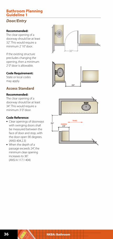
Bathroom Planning Guideline 1
Door/Entry
Recommended:
The clear opening of a
doorway should be at least
32”. This would require a
minimum 2’ 10” door.
If the existing structure
precludes changing the
opening, then a minimum
2’ 0” door is allowable.
Code Requirement:
State or local codes
may apply.
Access Standard
Recommended:
The clear opening of a
doorway should be at least
34”. This would require a
minimum 3’ 0” door.
Code Reference:
• Clear openings of doorways
with swinging doors shall
be measured between the
face of door and stop, with
the door open 90 degrees.
(ANSI 404.2.3)
• When the depth of a
passage exceeds 24”, the
minimum clear opening
increases to 36”.
(ANSI A 117.1 404)
36 NKBA: Bathroom
37Planning Guidelines with Access Standards
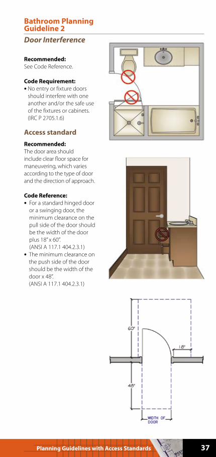
Bathroom Planning Guideline 2
Door Interference
Recommended:
See Code Reference.
Code Requirement:
• No entry or fixture doors
should interfere with one
another and/or the safe use
of the fixtures or cabinets.
(IRC P 2705.1.6)
Access standard
Recommended:
The door area should
include clear floor space for
maneuvering, which varies
according to the type of door
and the direction of approach.
Code Reference:
• For a standard hinged door
or a swinging door, the
minimum clearance on the
pull side of the door should
be the width of the door
plus 18” x 60”.
(ANSI A 117.1 404.2.3.1)
• The minimum clearance on
the push side of the door
should be the width of the
door x 48”.
(ANSI A 117.1 404.2.3.1)
38 NKBA: Bathroom
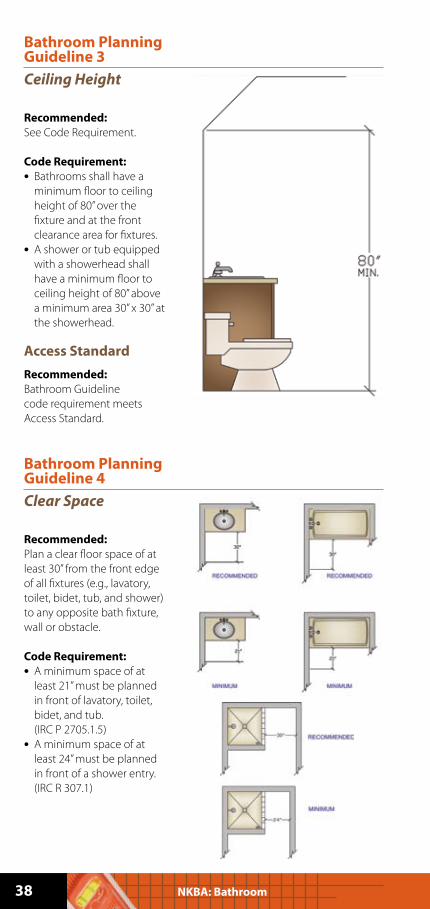
Bathroom Planning Guideline 3
Ceiling Height
Recommended:
See Code Requirement.
Code Requirement:
• Bathrooms shall have a
minimum floor to ceiling
height of 80” over the
fixture and at the front
clearance area for fixtures.
• A shower or tub equipped
with a showerhead shall
have a minimum floor to
ceiling height of 80” above
a minimum area 30” x 30” at
the showerhead.
Access Standard
Recommended:
Bathroom Guideline
code requirement meets
Access Standard.
Bathroom Planning Guideline 4
Clear Space
Recommended:
Plan a clear floor space of at
least 30” from the front edge
of all fixtures (e.g., lavatory,
toilet, bidet, tub, and shower)
to any opposite bath fixture,
wall or obstacle.
Code Requirement:
• A minimum space of at
least 21” must be planned
in front of lavatory, toilet,
bidet, and tub.
(IRC P 2705.1.5)
• A minimum space of at
least 24” must be planned
in front of a shower entry.
(IRC R 307.1)
39Planning Guidelines with Access Standards
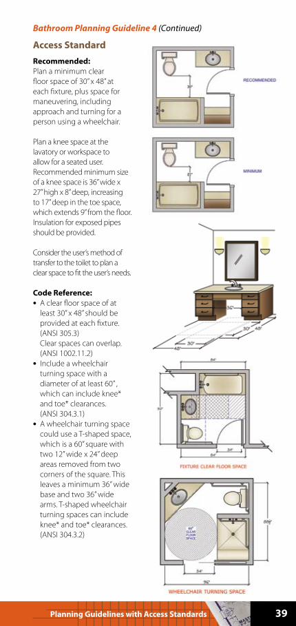
Access Standard
Recommended:
Plan a minimum clear
floor space of 30” x 48” at
each fixture, plus space for
maneuvering, including
approach and turning for a
person using a wheelchair.
Plan a knee space at the
lavatory or workspace to
allow for a seated user.
Recommended minimum size
of a knee space is 36” wide x
27” high x 8” deep, increasing
to 17” deep in the toe space,
which extends 9” from the floor.
Insulation for exposed pipes
should be provided.
Consider the user’s method of
transfer to the toilet to plan a
clear space to fit the user’s needs.
Code Reference:
• A clear floor space of at
least 30” x 48” should be
provided at each fixture.
(ANSI 305.3)
Clear spaces can overlap.
(ANSI 1002.11.2)
• Include a wheelchair
turning space with a
diameter of at least 60” ,
which can include knee*
and toe* clearances.
(ANSI 304.3.1)
• A wheelchair turning space
could use a T-shaped space,
which is a 60” square with
two 12” wide x 24” deep
areas removed from two
corners of the square. This
leaves a minimum 36” wide
base and two 36” wide
arms. T-shaped wheelchair
turning spaces can include
knee* and toe* clearances.
(ANSI 304.3.2)
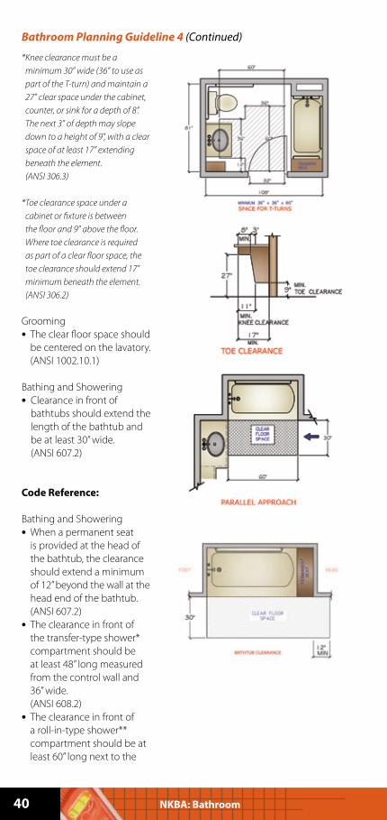
Bathroom Planning Guideline 4 (Continued)
40 NKBA: Bathroom
* Knee clearance must be a
minimum 30” wide (36” to use as
part of the T-turn) and maintain a
27” clear space under the cabinet,
counter, or sink for a depth of 8”.
The next 3” of depth may slope
down to a height of 9”, with a clear
space of at least 17” extending
beneath the element.
(ANSI 306.3)
* Toe clearance space under a
cabinet or fixture is between
the floor and 9” above the floor.
Where toe clearance is required
as part of a clear floor space, the
toe clearance should extend 17”
minimum beneath the element.
(ANSI 306.2)
Grooming
• The clear floor space should
be centered on the lavatory.
(ANSI 1002.10.1)
Bathing and Showering
• Clearance in front of
bathtubs should extend the
length of the bathtub and
be at least 30” wide.
(ANSI 607.2)
Code Reference:
Bathing and Showering
• When a permanent seat
is provided at the head of
the bathtub, the clearance
should extend a minimum
of 12” beyond the wall at the
head end of the bathtub.
(ANSI 607.2)
• The clearance in front of
the transfer-type shower*
compartment should be
at least 48” long measured
from the control wall and
36” wide.
(ANSI 608.2)
• The clearance in front of
a roll-in-type shower**
compartment should be at
least 60” long next to the
Bathroom Planning Guideline 4 (Continued)
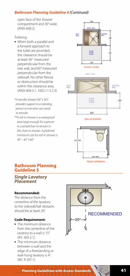
41Planning Guidelines with Access Standards
open face of the shower
compartment and 30” wide.
(ANSI 608.2)
Toileting
• When both a parallel and
a forward approach to
the toilet are provided,
the clearance should be
at least 56” measured
perpendicular from the
rear wall, and 60” measured
perpendicular from the
sidewall. No other fixture
or obstruction should be
within the clearance area.
(ANSI 604.3.1, 1002.11.5.2.3)
* A transfer shower (36” x 36”)
provides support to a standing
person or one who can stand
to transfer.
** A roll-in shower is a waterproof
area large enough for a person
in a wheelchair to remain in
the chair to shower. A preferred
minimum size for roll-in shower is
36” – 42” x 60”.
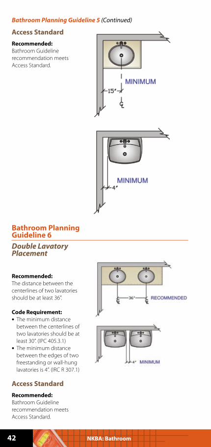
Bathroom Planning Guideline 5
Single Lavatory Placement
Recommended:
The distance from the
centerline of the lavatory
to the sidewall/tall obstacle
should be at least 20”.
Code Requirement:
• The minimum distance
from the centerline of the
lavatory to a wall is 15”.
(IPC 405.3.1)
• The minimum distance
between a wall and the
edge of a freestanding or
wall-hung lavatory is 4”.
(IRC R 307.1)
Bathroom Planning Guideline 4 (Continued)
42 NKBA: Bathroom
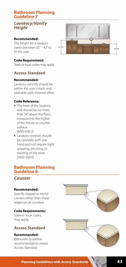
Bathroom Planning Guideline 5 (Continued)
Access Standard
Recommended:
Bathroom Guideline
recommendation meets
Access Standard.
Bathroom Planning Guideline 6
Double Lavatory Placement
Recommended:
The distance between the
centerlines of two lavatories
should be at least 36”.
Code Requirement:
• The minimum distance
between the centerlines of
two lavatories should be at
least 30”. (IPC 405.3.1)
• The minimum distance
between the edges of two
freestanding or wall-hung
lavatories is 4”. (IRC R 307.1)
Access Standard
Recommended:
Bathroom Guideline
recommendation meets
Access Standard.
43Planning Guidelines with Access Standards
Bathroom Planning Guideline 7
Lavatory/Vanity Height
Recommended:
The height for a lavatory
varies between 32” – 43” to
fit the user.
Code Requirement:
State or local codes may apply.
Access Standard
Recommended:
Lavatory controls should be
within the user’s reach and
operable with minimal effort.
Code Reference:
• The front of the lavatory
sink should be no more
than 34” above the floor,
measured to the higher
of the fixture or counter
surface.
(ANSI 606.3)
• Lavatory controls should
be operable with one
hand and not require tight
grasping, pinching, or
twisting of the wrist.
(ANSI 309.4)
Bathroom Planning Guideline 8
Counter
Recommended:
Specify clipped or round
corners rather than sharp
edges on all counters.
Code Requirements:
State or local codes
may apply.
Access Standard
Recommended:
Bathroom Guideline
recommendation meets
Access Standard.
44 NKBA: Bathroom
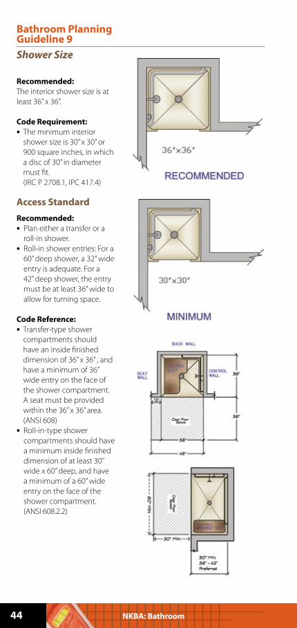
Bathroom Planning Guideline 9
Shower Size
Recommended:
The interior shower size is at
least 36” x 36”.
Code Requirement:
• The minimum interior
shower size is 30” x 30” or
900 square inches, in which
a disc of 30” in diameter
must fit.
(IRC P 2708.1, IPC 417.4)
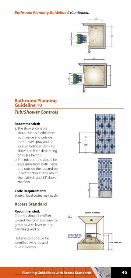
Access Standard
Recommended:
• Plan either a transfer or a
roll-in shower.
• Roll-in shower entries: For a
60” deep shower, a 32” wide
entry is adequate. For a
42” deep shower, the entry
must be at least 36” wide to
allow for turning space.
Code Reference:
• Transfer-type shower
compartments should
have an inside finished
dimension of 36” x 36” , and
have a minimum of 36”
wide entry on the face of
the shower compartment.
A seat must be provided
within the 36” x 36” area.
(ANSI 608)
• Roll-in-type shower
compartments should have
a minimum inside finished
dimension of at least 30”
wide x 60” deep, and have
a minimum of a 60” wide
entry on the face of the
shower compartment.
(ANSI 608.2.2)
45Planning Guidelines with Access Standards
Bathroom Planning Guideline 9 (Continued)
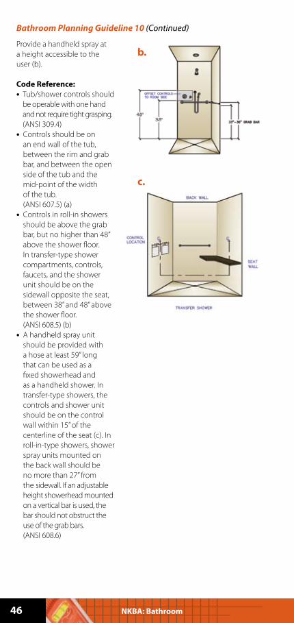
Bathroom Planning Guideline 10
Tub/Shower Controls
Recommended:
a. The shower controls
should be accessible from
both inside and outside
the shower spray and be
located between 38” – 48”
above the floor, depending
on user’s height.
b. The tub controls should be
accessible from both inside
and outside the tub and be
located between the rim of
the bathtub and 33” above
the floor.
Code Requirement:
State or local codes may apply.
Access Standard
Recommended:
Controls should be offset
toward the room and easy to
grasp, as with lever or loop
handles (a and b).
Hot and cold should be
identified with red and
blue indicators.
a.
46 NKBA: Bathroom
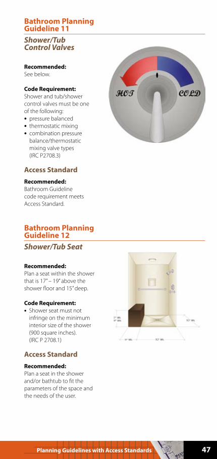
Provide a handheld spray at
a height accessible to the
user (b).
Code Reference:
• Tub/shower controls should
be operable with one hand
and not require tight grasping.
(ANSI 309.4)
• Controls should be on
an end wall of the tub,
between the rim and grab
bar, and between the open
side of the tub and the
mid-point of the width
of the tub.
(ANSI 607.5) (a)
• Controls in roll-in showers
should be above the grab
bar, but no higher than 48”
above the shower floor.
In transfer-type shower
compartments, controls,
faucets, and the shower
unit should be on the
sidewall opposite the seat,
between 38” and 48” above
the shower floor.
(ANSI 608.5) (b)
• A handheld spray unit
should be provided with
a hose at least 59” long
that can be used as a
fixed showerhead and
as a handheld shower. In
transfer-type showers, the
controls and shower unit
should be on the control
wall within 15” of the
centerline of the seat (c). In
roll-in-type showers, shower
spray units mounted on
the back wall should be
no more than 27” from
the sidewall. If an adjustable
height showerhead mounted
on a vertical bar is used, the
bar should not obstruct the
use of the grab bars.
(ANSI 608.6)
Bathroom Planning Guideline 10 (Continued)
b.
c.
47Planning Guidelines with Access Standards
Bathroom Planning Guideline 11
Shower/Tub Control Valves
Recommended:
See below.
Code Requirement:
Shower and tub/shower
control valves must be one
of the following:
• pressure balanced
• thermostatic mixing
• combination pressure
balance/thermostatic
mixing valve types
(IRC P2708.3)
Access Standard
Recommended:
Bathroom Guideline
code requirement meets
Access Standard.
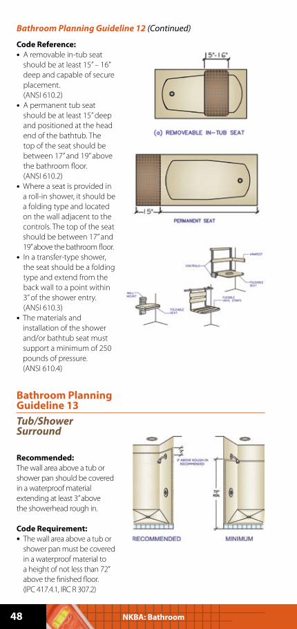
Bathroom Planning Guideline 12
Shower/Tub Seat
Recommended:
Plan a seat within the shower
that is 17” – 19” above the
shower floor and 15” deep.
Code Requirement:
• Shower seat must not
infringe on the minimum
interior size of the shower
(900 square inches).
(IRC P 2708.1)
Access Standard
Recommended:
Plan a seat in the shower
and/or bathtub to fit the
parameters of the space and
the needs of the user.
48 NKBA: Bathroom
Code Reference:
• A removable in-tub seat
should be at least 15” – 16”
deep and capable of secure
placement.
(ANSI 610.2)
• A permanent tub seat
should be at least 15” deep
and positioned at the head
end of the bathtub. The
top of the seat should be
between 17” and 19” above
the bathroom floor.
(ANSI 610.2)
• Where a seat is provided in
a roll-in shower, it should be
a folding type and located
on the wall adjacent to the
controls. The top of the seat
should be between 17” and
19” above the bathroom floor.
• In a transfer-type shower,
the seat should be a folding
type and extend from the
back wall to a point within
3” of the shower entry.
(ANSI 610.3)
• The materials and
installation of the shower
and/or bathtub seat must
support a minimum of 250
pounds of pressure.
(ANSI 610.4)
Bathroom Planning Guideline 12 (Continued)
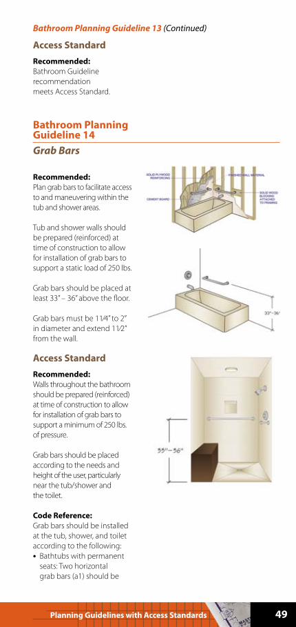
Bathroom Planning Guideline 13
Tub/Shower Surround
Recommended:
The wall area above a tub or
shower pan should be covered
in a waterproof material
extending at least 3” above
the showerhead rough in.
Code Requirement:
• The wall area above a tub or
shower pan must be covered
in a waterproof material to
a height of not less than 72”
above the finished floor.
(IPC 417.4.1, IRC R 307.2)
49Planning Guidelines with Access Standards
Access Standard
Recommended:
Bathroom Guideline
recommendation
meets Access Standard.
Bathroom Planning Guideline 13 (Continued)
Bathroom Planning Guideline 14
Grab Bars
Recommended:
Plan grab bars to facilitate access
to and maneuvering within the
tub and shower areas.
Tub and shower walls should
be prepared (reinforced) at
time of construction to allow
for installation of grab bars to
support a static load of 250 lbs.
Grab bars should be placed at
least 33” – 36” above the floor.
Grab bars must be 11⁄4” to 2”
in diameter and extend 11⁄2”
from the wall.
Access Standard
Recommended:
Walls throughout the bathroom
should be prepared (reinforced)
at time of construction to allow
for installation of grab bars to
support a minimum of 250 lbs.
of pressure.
Grab bars should be placed
according to the needs and
height of the user, particularly
near the tub/shower and
the toilet.
Code Reference:
Grab bars should be installed
at the tub, shower, and toilet
according to the following:
• Bathtubs with permanent
seats: Two horizontal
grab bars (a1) should be
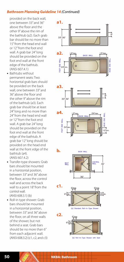
50 NKBA: Bathroom
provided on the back wall,
one between 33” and 36”
above the floor and the
other 9” above the rim of
the bathtub (a2). Each grab
bar should be no more than
15” from the head end wall
or 12” from the foot end
wall. A grab bar 24” long
should be provided on the
foot end wall at the front
edge of the bathtub.
(ANSI 607.4.1)
• Bathtubs without
permanent seats: Two
horizontal grab bars should
be provided on the back
wall, one between 33” and
36” above the floor and
the other 9” above the rim
of the bathtub (a3). Each
grab bar should be at least
24” long and no more than
24” from the head end wall
or 12” from the foot end
wall. A grab bar 24” long
should be provided on the
foot end wall at the front
edge of the bathtub. A
grab bar 12” long should be
provided on the head end
wall at the front edge of the
bathtub (a4).
(ANSI 607.4.2)
• Transfer-type showers: Grab
bars should be mounted
in a horizontal position,
between 33” and 36” above
the floor, across the control
wall and across the back
wall to a point 18” from the
control wall.
(ANSI 608.3.1) (b)
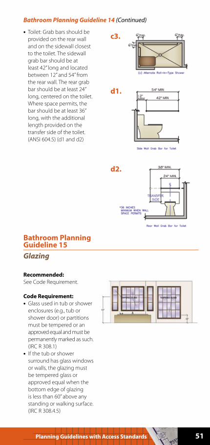
• Roll-in type shower: Grab
bars should be mounted
in a horizontal position,
between 33” and 36” above
the floor, on all three walls
of the shower, but not
behind a seat. Grab bars
should be no more than 6”
from each adjacent wall.
(ANSI 608.3.2) (c1, c2, and c3)
Bathroom Planning Guideline 14 (Continued)
a1.
a2.
a3.
a4.
b.
c1.
c2.
51Planning Guidelines with Access Standards
• Toilet: Grab bars should be
provided on the rear wall
and on the sidewall closest
to the toilet. The sidewall
grab bar should be at
least 42” long and located
between 12” and 54” from
the rear wall. The rear grab
bar should be at least 24”
long, centered on the toilet.
Where space permits, the
bar should be at least 36”
long, with the additional
length provided on the
transfer side of the toilet.
(ANSI 604.5) (d1 and d2)
Bathroom Planning Guideline 14 (Continued)
c3.
d1.
d2.
Bathroom Planning Guideline 15
Glazing
Recommended:
See Code Requirement.
Code Requirement:
• Glass used in tub or shower
enclosures (e.g., tub or
shower door) or partitions
must be tempered or an
approved equal and must be
permanently marked as such.
(IRC R 308.1)
• If the tub or shower
surround has glass windows
or walls, the glazing must
be tempered glass or
approved equal when the
bottom edge of glazing
is less than 60” above any
standing or walking surface.
(IRC R 308.4.5)
52 NKBA: Bathroom
• Any glazing (e.g., windows
or doors) whose bottom
edge is less than 18” above
the floor must be tempered
glass or approved equal.
(IRC R 308.4.7.2)
Access Standard
Recommended:
Bathroom Guideline
code requirements meet
Access Standard.
Bathroom Planning Guideline 15 (Continued)
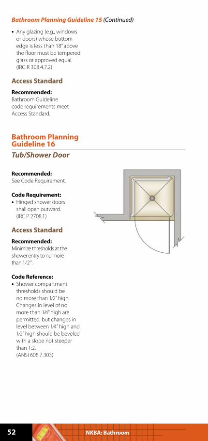
Bathroom Planning Guideline 16
Tub/Shower Door
Recommended:
See Code Requirement.
Code Requirement:
• Hinged shower doors
shall open outward.
(IRC P 2708.1)
Access Standard
Recommended:
Minimize thresholds at the
shower entry to no more
than 1⁄ 2”.
Code Reference:
• Shower compartment
thresholds should be
no more than 1⁄2” high.
Changes in level of no
more than 1⁄4” high are
permitted, but changes in
level between 1⁄4” high and
1⁄2” high should be beveled
with a slope not steeper
than 1:2.
(ANSI 608.7.303)
53Planning Guidelines with Access Standards
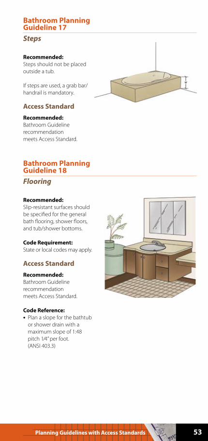
Bathroom Planning Guideline 17
Steps
Recommended:
Steps should not be placed
outside a tub.
If steps are used, a grab bar/
handrail is mandatory.
Access Standard
Recommended:
Bathroom Guideline
recommendation
meets Access Standard.
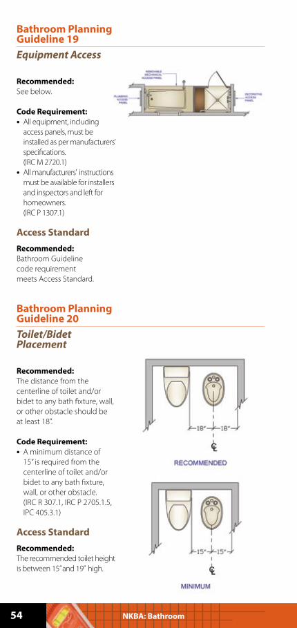
Bathroom Planning Guideline 18
Flooring
Recommended:
Slip-resistant surfaces should
be specified for the general
bath flooring, shower floors,
and tub/shower bottoms.
Code Requirement:
State or local codes may apply.
Access Standard
Recommended:
Bathroom Guideline
recommendation
meets Access Standard.
Code Reference:
• Plan a slope for the bathtub
or shower drain with a
maximum slope of 1:48
pitch 1⁄4” per foot.
(ANSI 403.3)
54 NKBA: Bathroom
Bathroom Planning Guideline 19
Equipment Access
Recommended:
See below.
Code Requirement:
• All equipment, including
access panels, must be
installed as per manufacturers’
specifications.
(IRC M 2720.1)
• All manufacturers’ instructions
must be available for installers
and inspectors and left for
homeowners.
(IRC P 1307.1)
Access Standard
Recommended:
Bathroom Guideline
code requirement
meets Access Standard.
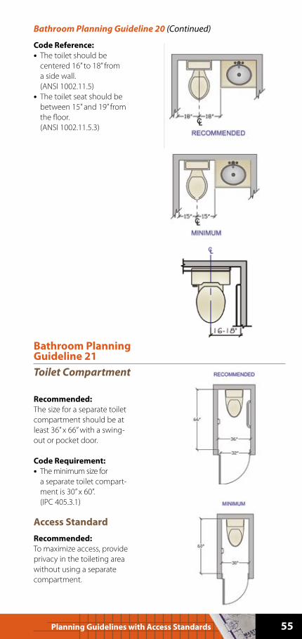
Bathroom Planning Guideline 20
Toilet/Bidet Placement
Recommended:
The distance from the
centerline of toilet and/or
bidet to any bath fixture, wall,
or other obstacle should be
at least 18”.
Code Requirement:
• A minimum distance of
15” is required from the
centerline of toilet and/or
bidet to any bath fixture,
wall, or other obstacle.
(IRC R 307.1, IRC P 2705.1.5,
IPC 405.3.1)
Access Standard
Recommended:
The recommended toilet height
is between 15” and 19” high.
55Planning Guidelines with Access Standards
Code Reference:
• The toilet should be
centered 16” to 18” from
a side wall.
(ANSI 1002.11.5)
• The toilet seat should be
between 15” and 19” from
the floor.
(ANSI 1002.11.5.3)
Bathroom Planning Guideline 20 (Continued)
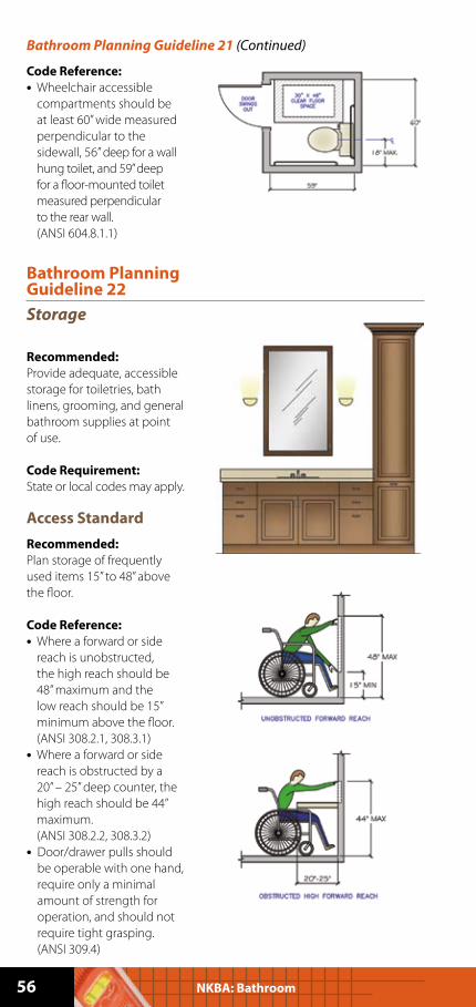
Bathroom Planning Guideline 21
Toilet Compartment
Recommended:
The size for a separate toilet
compartment should be at
least 36” x 66” with a swing-
out or pocket door.
Code Requirement:
• The minimum size for
a separate toilet compart-
ment is 30” x 60”.
(IPC 405.3.1)
Access Standard
Recommended:
To maximize access, provide
privacy in the toileting area
without using a separate
compartment.
56 NKBA: Bathroom
Code Reference:
• Wheelchair accessible
compartments should be
at least 60” wide measured
perpendicular to the
sidewall, 56” deep for a wall
hung toilet, and 59” deep
for a floor-mounted toilet
measured perpendicular
to the rear wall.
(ANSI 604.8.1.1)
Bathroom Planning Guideline 21 (Continued)
Bathroom Planning Guideline 22
Storage
Recommended:
Provide adequate, accessible
storage for toiletries, bath
linens, grooming, and general
bathroom supplies at point
of use.
Code Requirement:
State or local codes may apply.
Access Standard
Recommended:
Plan storage of frequently
used items 15” to 48” above
the floor.
Code Reference:
• Where a forward or side
reach is unobstructed,
the high reach should be
48” maximum and the
low reach should be 15”
minimum above the floor.
(ANSI 308.2.1, 308.3.1)
• Where a forward or side
reach is obstructed by a
20” – 25” deep counter, the
high reach should be 44”
maximum.
(ANSI 308.2.2, 308.3.2)
• Door/drawer pulls should
be operable with one hand,
require only a minimal
amount of strength for
operation, and should not
require tight grasping.
(ANSI 309.4)
57Planning Guidelines with Access Standards
Bathroom Planning Guideline 23
Accessories
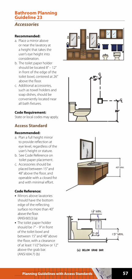
Recommended:
a. Place a mirror above
or near the lavatory at
a height that takes the
user’s eye height into
consideration.
b. The toilet paper holder
should be located 8” – 12”
in front of the edge of the
toilet bowl, centered at 26”
above the floor.
c. Additional accessories,
such as towel holders and
soap dishes, should be
conveniently located near
all bath fixtures.
Code Requirement:
State or local codes may apply.
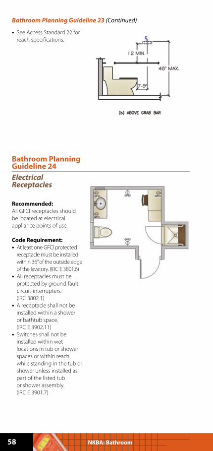
Access Standard
Recommended:
a. Plan a full height mirror
to provide reflection at
eye level, regardless of the
user’s height or stature.
b. See Code Reference on
toilet paper placement.
c. Accessories should be
placed between 15” and
48” above the floor, and
operable with a closed fist
and with minimal effort.
Code Reference:
• Mirrors above lavatories
should have the bottom
edge of the reflecting
surface no more than 40”
above the floor.
(ANSI 603.3) (a)
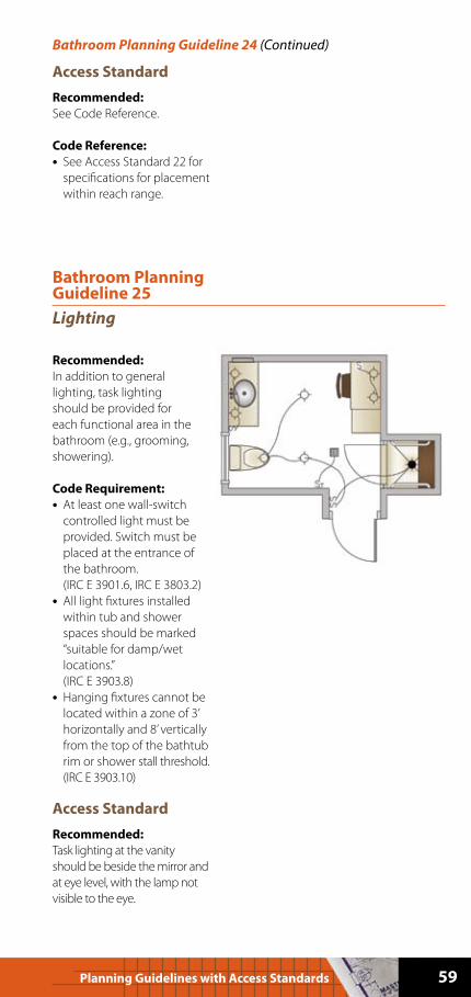
• The toilet paper holder
should be 7” – 9” in front
of the toilet bowl and
between 15” and 48” above
the floor, with a clearance
of at least 11⁄2” below or 12”
above the grab bar.
(ANSI 604.7) (b)
58 NKBA: Bathroom
• See Access Standard 22 for
reach specifications.
Bathroom Planning Guideline 23 (Continued)
Bathroom Planning Guideline 24
Electrical Receptacles
Recommended:
All GFCI receptacles should
be located at electrical
appliance points of use.
Code Requirement:
• At least one GFCI protected
receptacle must be installed
within 36” of the outside edge
of the lavatory. (IRC E 3801.6)
• All receptacles must be
protected by ground-fault
circuit-interrupters.
(IRC 3802.1)
• A receptacle shall not be
installed within a shower
or bathtub space.
(IRC E 3902.11)
• Switches shall not be
installed within wet
locations in tub or shower
spaces or within reach
while standing in the tub or
shower unless installed as
part of the listed tub
or shower assembly.
(IRC E 3901.7)
59Planning Guidelines with Access Standards
Access Standard
Recommended:
See Code Reference.
Code Reference:
• See Access Standard 22 for
specifications for placement
within reach range.
Bathroom Planning Guideline 24 (Continued)
Bathroom Planning Guideline 25
Lighting
Recommended:
In addition to general
lighting, task lighting
should be provided for
each functional area in the
bathroom (e.g., grooming,
showering).
Code Requirement:
• At least one wall-switch
controlled light must be
provided. Switch must be
placed at the entrance of
the bathroom.
(IRC E 3901.6, IRC E 3803.2)
• All light fixtures installed
within tub and shower
spaces should be marked
“suitable for damp/wet
locations.”
(IRC E 3903.8)
• Hanging fixtures cannot be
located within a zone of 3’
horizontally and 8’ vertically
from the top of the bathtub
rim or shower stall threshold.
(IRC E 3903.10)
Access Standard
Recommended:
Task lighting at the vanity
should be beside the mirror and
at eye level, with the lamp not
visible to the eye.
60 NKBA: Bathroom
Lighting controls should be
between 15” and 48” above the
floor and operable with a closed
fist and with minimal effort.
Code Reference:
• Operable parts should be
operable with one hand
and not require tight
grasping, pinching, or
twisting of the wrist. The
force required to activate
operable parts should be 5
pounds maximum.
(ANSI A117.1 309.4)
• See Access Standard 22
for specifications for reach
range for controls.
Bathroom Planning Guideline 26
Ventilation
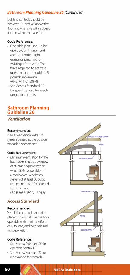
Recommended:
Plan a mechanical exhaust
system, vented to the outside,
for each enclosed area.
Code Requirement:
• Minimum ventilation for the
bathroom is to be a window
of at least 3 square feet, of
which 50% is operable, or
a mechanical ventilation
system of at least 50 cubic
feet per minute (cfm) ducted
to the outside.
(IRC R 303.3, IRC M 1506.3)
Access Standard
Recommended:
Ventilation controls should be
placed 15” – 48” above the floor,
operable with minimal effort,
easy to read, and with minimal
noise pollution.
Code Reference:
• See Access Standard 25 for
operable controls.
• See Access Standard 22 for
reach range for controls.
Bathroom Planning Guideline 25 (Continued)
61Planning Guidelines with Access Standards
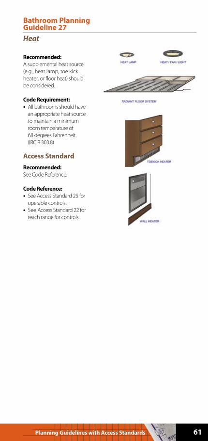
Bathroom Planning Guideline 27
Heat
Recommended:
A supplemental heat source
(e.g., heat lamp, toe kick
heater, or floor heat) should
be considered.
Code Requirement:
• All bathrooms should have
an appropriate heat source
to maintain a minimum
room temperature of
68 degrees Fahrenheit.
(IRC R 303.8)
Access Standard
Recommended:
See Code Reference.
Code Reference:
• See Access Standard 25 for
operable controls.
• See Access Standard 22 for
reach range for controls.

62 NKBA: Bathroom
Notes:

63Planning Guidelines with Access Standards
Notes:

Notes:
64 NKBA: Bathroom
65Planning Guidelines with Access Standards
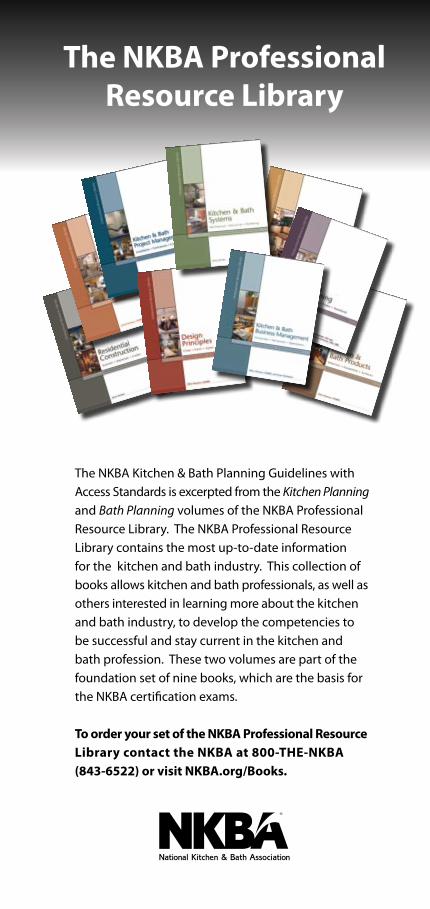
The NKBA Kitchen & Bath Planning Guidelines with
Access Standards is excerpted from the Kitchen Planning
and Bath Planning volumes of the NKBA Professional
Resource Library. The NKBA Professional Resource
Library contains the most up-to-date information
for the kitchen and bath industry. This collection of
books allows kitchen and bath professionals, as well as
others interested in learning more about the kitchen
and bath industry, to develop the competencies to
be successful and stay current in the kitchen and
bath profession. These two volumes are part of the
foundation set of nine books, which are the basis for
the NKBA certification exams.
To order your set of the NKBA Professional Resource
Library contact the NKBA at 800-THE-NKBA
(843-6522) or visit NKBA.org/Books.
The NKBA Professional
Resource Library
66 NKBA: Kitchen
The National Kitchen & Bath Association repre-
sents the finest professionals in the industry. The
NKBA is a non-profit trade association that has
educated and led the kitchen and bath industry
since 1963. With more than 40,000 members and
growing, NKBA owns the Kitchen & Bath Industry
Show (KBIS®). The mission of the NKBA is to en-
hance member success and excellence, promote
professionalism and ethical business practices
and provide leadership and direction for the
kitchen and bath industry.
To learn more about becoming a member, visit
our web site at NKBA.org/Join or call an NKBA
Customer Service Representative at 800-THE-NKBA
(800-843-6522).
5401