Cutting Edge Inc - ELANPORTAL.COM · Multiple A/V Zones: TS2s will support ONE Audio/Video Zone....
15
1 of 15 The TS2 has the ability to control a Single Zone of a multi-room g! System. It does not have the capabilities to control multiple zones like other g! User Interfaces. Manufacturer: ELAN Home Systems Model Number(s): TS2, TS2L Software Versions: Automation Controller - 5.0 build 637 or later ELAN SC1 - 1.0.4.1 ELAN TS2 - 1.6.0.2 or newer g!Tools 7.2.338 or later Document Revision Date: 8/17/2015 Overview and Supported Features TS2 keypads communicate on a dedicated VIANET bus to provide a compact single zone two-way user interface for an ELAN g! System. ELAN g!SC Controllers (gSC2 and gSC10) require an ELAN SC1 serial controller (RS- 232- to- VIANET) to communicate with the keypads. ELAN HC series controllers (HC4, HC6, HC8 and HC12) have a VIANET jack built in and do not require the SC1. Up to 32 keypads can be connected on a single VIANET bus. Note: When utilized, the SC1 must be connected to a serial port on the system controller. It is NOT compatible with SerialBricks, Global Cache ports, or Moxa ports. The SC1 must also be using the firmware version shown above (or newer). Refer to the TS2 Installation Manual for detailed installation diagrams and power requirements: http://www.elanportal.com/supportdocs/catalog/TS2_Manual_RevD_9901068.pdf TS2 Quick Reference Installation Guide: http://www.elanportal.com/supportdocs/catalog/TS2%20QUICK%20INSTALL%20GUIDE%209901 052%20RevA.pdf
Transcript of Cutting Edge Inc - ELANPORTAL.COM · Multiple A/V Zones: TS2s will support ONE Audio/Video Zone....

1 of 15
The TS2 has the ability to control a Single Zone of a multi-room g! System. It does not have
the capabilities to control multiple zones like other g! User Interfaces.
Integration Note
Manufacturer: ELAN Home Systems
Model Number(s): TS2, TS2L
Software Versions:
Automation Controller - 5.0 build 637 or later ELAN SC1 - 1.0.4.1 ELAN TS2 - 1.6.0.2 or newer g!Tools 7.2.338 or later
Document Revision Date: 8/17/2015
Overview and Supported Features
TS2 keypads communicate on a dedicated VIANET bus to provide a compact single zone
two-way user interface for an ELAN g! System.
ELAN g!SC Controllers (gSC2 and gSC10) require an ELAN SC1 serial controller (RS-
232- to- VIANET) to communicate with the keypads.
ELAN HC series controllers (HC4, HC6, HC8 and HC12) have a VIANET jack built in and
do not require the SC1.
Up to 32 keypads can be connected on a single VIANET bus.
Note: When utilized, the SC1 must be connected to a serial port on the system controller. It is
NOT compatible with SerialBricks, Global Cache ports, or Moxa ports. The SC1 must also be
using the firmware version shown above (or newer).
Refer to the TS2 Installation Manual for detailed installation diagrams and power requirements:
http://www.elanportal.com/supportdocs/catalog/TS2_Manual_RevD_9901068.pdf
TS2 Quick Reference Installation Guide:
http://www.elanportal.com/supportdocs/catalog/TS2%20QUICK%20INSTALL%20GUIDE%209901
052%20RevA.pdf

2 of 15
TS2 Keypads support the following features:
System Mode Control: The home interface may be optionally configured to provide System Mode
Status and Control.
Basic Time & Weather information: The Home interface may be optionally configured to display
Time and basic Weather information.
Lighting Control: The Lighting interface displays a custom lighting keypad for 2-way control of
Scenes or Lighting Loads.
Security Control: The Security interface displays status of one Partition and a keypad to
Arm/Disarm it.
Climate Control: The Climate interface displays status of one Climate Zone and provides Mode,
Fan, and Set Point adjustments.
Media Control: The Media interface displays status of one Media Zone and provides controls for
Power, Source, Volume, Mute, and basic Source control. The interface provides metadata
feedback (no cover art at this time) for supported two-way devices or customizable single or multi-
page interfaces for one-way device control. See limitations below.
TS2 Keypads DO NOT support the following features:
Various Custom Controls: Not all custom controls are supported on the TS2 interface. The result
of this may be limited source control of various 3rd
party AV sources.
Multiple A/V Zones: TS2s will support ONE Audio/Video Zone. They will not control multiple
zones like other g! User Interfaces.
Multiple Security Partitions: TS2s display status for ONE Security Partition and the ability to
Arm/Disarm that partition. Multiple Partitions cannot be controlled with TS2s.
Multiple Climate Zones: TS2s provide control of ONE Climate zone. Multiple Climate Zones
cannot be controlled.
Installation Overview
1. Install wiring for TS2 as described in the TS2 Installation Manual
http://www.elanportal.com/supportdocs/catalog/TS2_Manual_RevD_9901068.pdf
2. Connect TS2 to system controller as shown in the appropriate Connection Diagrams, below.
3. Verify that the TS2 firmware is up to date as listed in Software Versions, above.
4. Configure programming for TS2s using g!Tools software..
5. Test functionality.
Any feature not listed as Supported is NOT Supported.
3 of 15
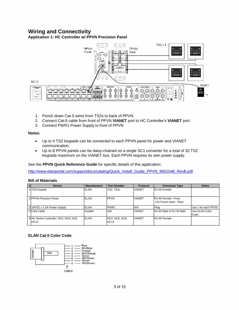
Wiring and Connectivity Application 1: HC Controller w/ PPVN Precision Panel
1. Punch down Cat-5 wires from TS2s to back of PPVN.
2. Connect Cat-5 cable from front of PPVN VIANET port to HC Controller’s VIANET port.
3. Connect PWR1 Power Supply to front of PPVN
Notes:
Up to 4 TS2 keypads can be connected to each PPVN panel for power and VIANET
communication.
Up to 8 PPVN panels can be daisy-chained on a single SC1 converter for a total of 32 TS2
keypads maximum on the VIANET bus. Each PPVN requires its own power supply.
See the PPVN Quick Reference Guide for specific details of this application:
http://www.elanportal.com/supportdocs/catalog/Quick_Install_Guide_PPVN_9901048_RevB.pdf.
Bill of Materials
# Device Manufacturer Part Number Protocol Connector Type Notes 1 TS2 Keypad ELAN TS2, TS2L VIANET RJ-45 Female
2 PPVN Precision Panel ELAN PPVN VIANET RJ-45 Female –Front
110 Punch down - Rear
3 16VDC x 1.5A Power Supply ELAN PWR1 N/A Plug Use 1 for each PPVN 4 Cat5 Cable Installer N/A VIANET RJ-45 Male to RJ-45 Male Use ELAN Color
Code 5 HC Series Controller: HC4, HC6, HC8,
HC12 ELAN HC4, HC6, HC8,
HC12 VIANET RJ-45 Female
ELAN Cat-5 Color Code

4 of 15
Application 2: gSC2 / gSC10 Controller w/ PPVN Precision Panel
1. Punch down Cat-5 wires from TS2s to back of PPVN using ELAN color code.
2. Connect Cat-5 cable from front of PPVN VIANET port to VIANET IN port of SC1.
3. Use the included RJ-45 to RJ-45 crossover cable (P/N 7600218) to connect the RS232
CONTROL port of the SC1 to an open serial port on gSC2 or gSC10. If you need a
crossover cable longer than what has been included, see the diagram below.
4. Connect PWR1 16 VDC Power Supply to front of PPVN.
5. Connect PWR3 12 VDC Power Supply to SC1.
Notes:
Up to 4 TS2 keypads can be connected to each PPVN panel for power and VIANET
communication.
Up to 8 PPVN panels can be daisy-chained on a single SC1 converter for a total of 32 TS2
keypads maximum on the VIANET bus. Each PPVN requires its own power supply.
Make absolutely sure to use the included crossover cable (P/N 7600218) where specified.
The system will not work unless this is correct!
See the SC1 Installation Manual for specific details of this application:
http://www.elanportal.com/supportdocs/catalog/SC1_Installation_Manual.pdf
See the PPVN Quick Reference Guide for specific details of this application:
http://www.elanportal.com/supportdocs/catalog/Quick_Install_Guide_PPVN_9901048_RevB.pdf
Bill of Materials # Device Manufacturer Part Number Protocol Connector Type Notes 1 TS2 Keypad ELAN TS2, TS2L VIANET RJ-45 Female 2 PPVN Precision Panel ELAN PPVN VIANET RJ-45 Female –Front
110 Punch down - Rear
3 16VDC x 1.5A Power Supply ELAN PWR1 N/A Plug Use 1 for each PPVN 4 Cat-5 Cable Installer N/A VIANET RJ-45 Male to RJ-45 Male Use ELAN Color Code 5 SC-1 Serial Controller ELAN SC1 VIANET
RS-232 RJ-45 Female
6 Cat-5 Crossover Cable ELAN 7600218 RS-232 RJ-45 Male to RJ-45 Male Included w/ SC1 7 g!SC Series Controller: gSC2, gSC10 ELAN gSC2, gSC10 RS-232 RJ-45 Male
5 of 15
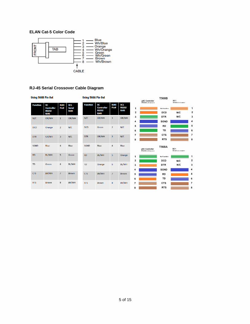
ELAN Cat-5 Color Code
RJ-45 Serial Crossover Cable Diagram
6 of 15
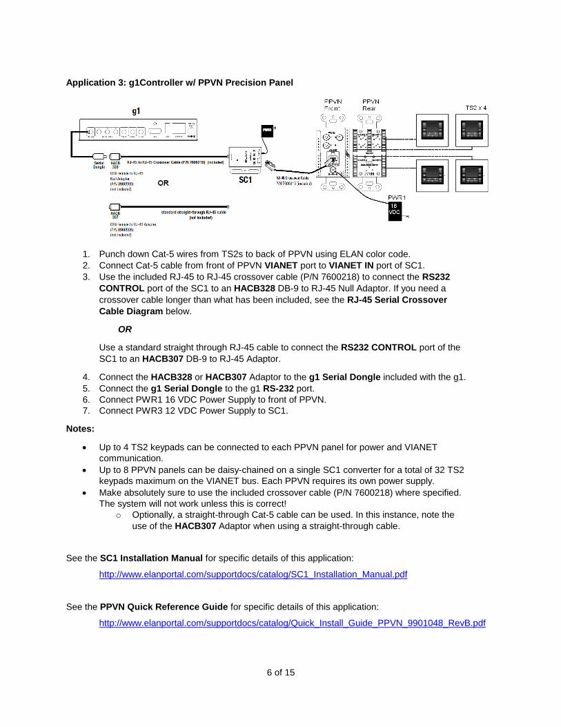
Application 3: g1Controller w/ PPVN Precision Panel
1. Punch down Cat-5 wires from TS2s to back of PPVN using ELAN color code.
2. Connect Cat-5 cable from front of PPVN VIANET port to VIANET IN port of SC1.
3. Use the included RJ-45 to RJ-45 crossover cable (P/N 7600218) to connect the RS232
CONTROL port of the SC1 to an HACB328 DB-9 to RJ-45 Null Adaptor. If you need a
crossover cable longer than what has been included, see the RJ-45 Serial Crossover
Cable Diagram below.
OR
Use a standard straight through RJ-45 cable to connect the RS232 CONTROL port of the
SC1 to an HACB307 DB-9 to RJ-45 Adaptor.
4. Connect the HACB328 or HACB307 Adaptor to the g1 Serial Dongle included with the g1.
5. Connect the g1 Serial Dongle to the g1 RS-232 port.
6. Connect PWR1 16 VDC Power Supply to front of PPVN.
7. Connect PWR3 12 VDC Power Supply to SC1.
Notes:
Up to 4 TS2 keypads can be connected to each PPVN panel for power and VIANET
communication.
Up to 8 PPVN panels can be daisy-chained on a single SC1 converter for a total of 32 TS2
keypads maximum on the VIANET bus. Each PPVN requires its own power supply.
Make absolutely sure to use the included crossover cable (P/N 7600218) where specified.
The system will not work unless this is correct!
o Optionally, a straight-through Cat-5 cable can be used. In this instance, note the
use of the HACB307 Adaptor when using a straight-through cable.
See the SC1 Installation Manual for specific details of this application:
http://www.elanportal.com/supportdocs/catalog/SC1_Installation_Manual.pdf
See the PPVN Quick Reference Guide for specific details of this application:
http://www.elanportal.com/supportdocs/catalog/Quick_Install_Guide_PPVN_9901048_RevB.pdf

7 of 15
Bill of Materials # Device Manufact
urer Part Number Protocol Connector Type Notes
1 TS2 Keypad ELAN TS2, TS2L VIANET RJ-45 Female 2 PPVN Precision Panel ELAN PPVN VIANET RJ-45 Female –Front
110 Punch down - Rear
3 16VDC x 1.5A Power Supply ELAN PWR1 N/A Plug Use 1 for each PPVN 4 Cat-5 Cable Installer N/A VIANET RJ-45 Male to RJ-45 Male Use ELAN Color Code 5 Serial Controller ELAN SC1 VIANET
RS-232 RJ-45 Female
6 Cat-5 Crossover Cable ELAN 7600218 RS-232 RJ-45 Male to RJ-45 Male Included w/ SC1 Optional: Cat-5 Standard Cable Installer N/A RS-232 RJ-45 Male to RJ-45 Male Optional: See Installation steps.
7 DB-9 to RJ-45 Null Adaptor ELAN HACB328 (P/N 8900599) RS-232 RJ-45 Male to DB-9 Female Null
Use w/ Crossover Cable Assembly
Optional: DB-9 to RJ-45 Adaptor ELAN HACB307 (P/N 8900598) RS-232 RJ-45 Male to DB-9 Female Use w/ straight-through cable assembly
8 ELAN RS-232 Adaptor ELAN 7600219 RS-232 DB-9 Male to 3.5mm Male Included w/ g!
9 g1 Controller ELAN g1 RS-232 3.5mm Female
ELAN Cat-5 Color Code
RJ-45 Serial Crossover Cable Diagram
Initial Keypad Configuration
TS2 keypads are automatically added to the system using Configurator software and cannot be
added manually. Follow the steps below to add TS2 keypads to a g! System:
1. Using the methods described above and in the various manuals, ensure that all
connections are made correctly, then power up all keypads by plugging in the power supply for
the PPVN. Make sure that power is applied to the system controller and SC1, if used.
2. In ELAN Configurator software, add the SC1 (if used) as a Communication Device and
select the COM port of the ELAN Controller that is being utilized. This is done on the Interface
Tab.

8 of 15
3. The keypads should boot to a Menu with GET ADDRESS as an option.
If the keypad does not boot to the GET ADDRESS screen, then follow these steps:
a. Press the Service Menu button once (located behind bezel and below Mini-
USB connection and light sensor) to access the MAIN MENU screen.
b. Press the UP/DOWN buttons to highlight VNet addr then press the Enter
button.
c. Press the UP/DOWN buttons to highlight Reset addr then press Enter.
9 of 15
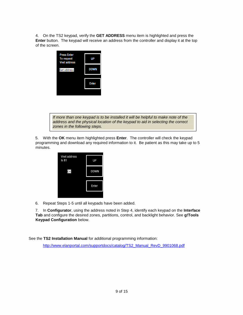
4. On the TS2 keypad, verify the GET ADDRESS menu item is highlighted and press the
Enter button. The keypad will receive an address from the controller and display it at the top
of the screen.
5. With the OK menu item highlighted press Enter. The controller will check the keypad
programming and download any required information to it. Be patient as this may take up to 5
minutes.
6. Repeat Steps 1-5 until all keypads have been added.
7. In Configurator, using the address noted in Step 4, identify each keypad on the Interface
Tab and configure the desired zones, partitions, control, and backlight behavior. See g!Tools
Keypad Configuration below.
See the TS2 Installation Manual for additional programming information:
http://www.elanportal.com/supportdocs/catalog/TS2_Manual_RevD_9901068.pdf
If more than one keypad is to be installed it will be helpful to make note of the address and the physical location of the keypad to aid in selecting the correct zones in the following steps.

10 of 15
g!Tools Keypad Configuration
Use ELAN g!Tools Configurator to finalize installation and determine the behavior of the TS2.
Many of the variable for programming - System #, Driver Version, Device Type and ViaNET ID are predetermined and, therefore, do not need to be adjusted.
Name, Communications Device, Enable Weather/Forecast/Sys Mode Pages
Name: Type an identifying Name for this TS2. Ex: TS2 ViaNet 81.
Communications Device o g!SC-based system: VIANET SC-1 o HC-based system: VIANET
Enable Weather Page: Yes or No to display local weather information
Enable Forecast Page: Yes or No to enable local weather forecast functions
Enable Sys Mode Page: Yes or No to enable the System Mode Page

11 of 15
Selecting a Media Zone
Configures TS2 to control one Media Zone
Select the correctly identified TS2 – TS2 ViaNet 81 in this example. o Interface Tab -> Interface Devices (TS2) -> TS2 ViaNet 81 -> Media Zone->
Select desired Media Zone
Selecting a Security Partition #1, #2, #3 Configures TS2 to control up to three Security Partitions
Select the correctly identified TS2 – TS2 ViaNet 81 in this example. o Interface Tab -> Interface Devices (TS2) -> TS2 ViaNet 81 -> Security #1->
Select desired Security Partition o Repeat procedure for Security #2 and Security #3

12 of 15
Selecting a Lighting Keypad #1, #2, #3
Configures TS2 to control up to three Lighting keypads
Select the correctly identified TS2 – TS2 ViaNet 81 in this example. o Interface Tab -> Interface Devices (TS2) -> TS2 ViaNet 81 -> Lighting Keypad
#1-> Select desired Lighting Keypad o Repeat procedure for Lighting Keypad #2 and Lighting Keypad #3
Selecting a Thermostat
Selects a single Thermostat for each TS2
Select the correctly identified TS2 – TS2 ViaNet 81 in this example. o Interface Tab -> Interface Devices (TS2) -> TS2 ViaNet 81 -> Thermostat->
Select desired Thermostat

13 of 15
Backlight Timeout Setting
Controls Backlight Timeout values
Select the previously identified TS2 – TS2 ViaNet 81 in this example. o Interface Tab -> Interface Devices (TS2) -> TS2 ViaNet 81 -> Backlight
Timeout -> Select desired value.

14 of 15
g!Tools Configurator Details The following table provides settings used in ELAN g!Tools Configurator. Please refer to the
Configurator Reference Guide for specific details.
http://www.elanportal.com/supportdocs/catalog/g_Configurator_Reference_6_2.pdf
<Select> Select the appropriate item from the list (or drop-down) in Configurator.
<User Defined> Type in the desired name for the item.
<Auto> This field will automatically populate during configuration
Devices Variable Name Setting Comments Communication Devices Name <User Defined> (Example: ELAN
SC1)
Type Serial Port
Communication Type VIANET SC1
Location <User Defined> (Not Required)
COM Port <Select>
Interface Devices<Auto
Discover> Name <User Defined> (Default: TS2
VIANET XX) See Note#1
Device Type ELAN TS2
COM Device <Auto> (Default: ELAN SC) See Note #2
VIANET ID <Auto> See Note #3
Enable Weather Page <Select> See Note #4
Enable Forecast
Page <Select> See Note #4
Enable Sys Mode
Page <Select> See Note #4
Media Zone <Select> See Note #5
Security Partition <Select> See Note #5
Lighting Keypad <Select> See Note #5
Thermostat <Select> See Note #5
Backlight Timeout <Select> See Note #5
Notes: 1. The TS2 keypads are automatically discovered, refer to Initial Keypad Configuration section above 2. If not already chosen, select the COM device that refers the TS2 to the proper SC1 and COM port. 3. The TS2 keypad IDs will be addressed automatically as they are imported into the system. 4. Select <Yes> to enable the optional page 5. Select the desired Zone, Partition, or Behavior for each keypad

15 of 15
Common Mistakes:
Not using a null-modem connection between the controller and the SC1 (if utilized).
Improper firmware in SC1 (if utilized). Firmware should be 1.0.3.9 or higher.
Not waiting for all programming transfers to complete.
o Initial transfer to newly installed TS2 keypads can take up to 5 minutes per unit,
e.g., eight TS2 keypads ~ 40 minutes.
o After the initial transfer, additional programming changes should occur very
quickly.
o TS2 keypads will appear to be non-functional while VIANET is transferring initial
data or firmware updates but can be used normally once programming is
complete.