CUSTOMIZER Installation and User Manual - Kanardia...Customizer | Manual 2.2 Installation 5.Open...
31
CUSTOMIZER Installation and User Manual Kanardia d.o.o. May 2020 Revision 1.2
Transcript of CUSTOMIZER Installation and User Manual - Kanardia...Customizer | Manual 2.2 Installation 5.Open...

CUSTOMIZER
Installation and User Manual
© Kanardia d.o.o.
May 2020
Revision 1.2
Customizer — Manual
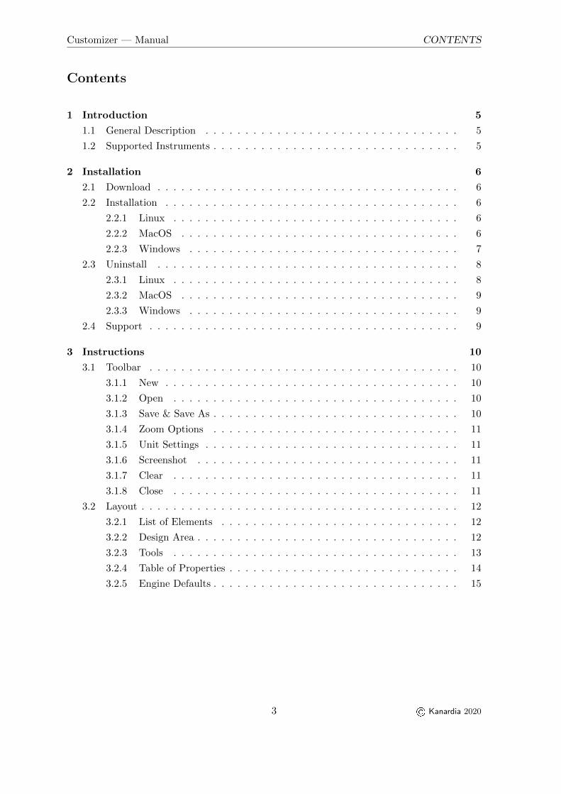
Contact Information
Publisher and producer:Kanardia d.o.o.Lopata 24aSI-3000Slovenia
Tel: +386 40 360 512Email: [email protected]
A lot of useful and recent information can be also found on the Internet.
See http://www.kanardia.eu for more details.
Copyright
This document is published under the Creative Commons, Attribution-ShareAlike 3.0 Un-ported licence. Full license is available on http://creativecommons.org/licenses/by-sa/
3.0/legalcode web page and a bit more human readable summary is given on http:
//creativecommons.org/licenses/by-sa/3.0/. In short, the license gives you right tocopy, reproduce and modify this document if:
� you cite Kanardia d.o.o. as the author of the original work,
� you distribute the resulting work only under the same or similar license to this one.
Credits
This document was written using TeTeX (LATEX) based document creation system using Kilerunning on Linux operating syseeetem. Most of the figures were drawn using Inkscape. Photosand scanned material was processed using Gimp (GNU Image Manipulation Program).
All document sources are freely available on request under the licence mentioned above andcan be obtained by email. Please send requests to [email protected].
Revision History
The following table shows the revision heistory of this document.
Rev. Date Description
1.0 March 2020 Initial release
1.1 April 2020 Third Party Software section added
1.2 May 2020 Minor fixes
2 © Kanardia 2020
Customizer — Manual CONTENTS
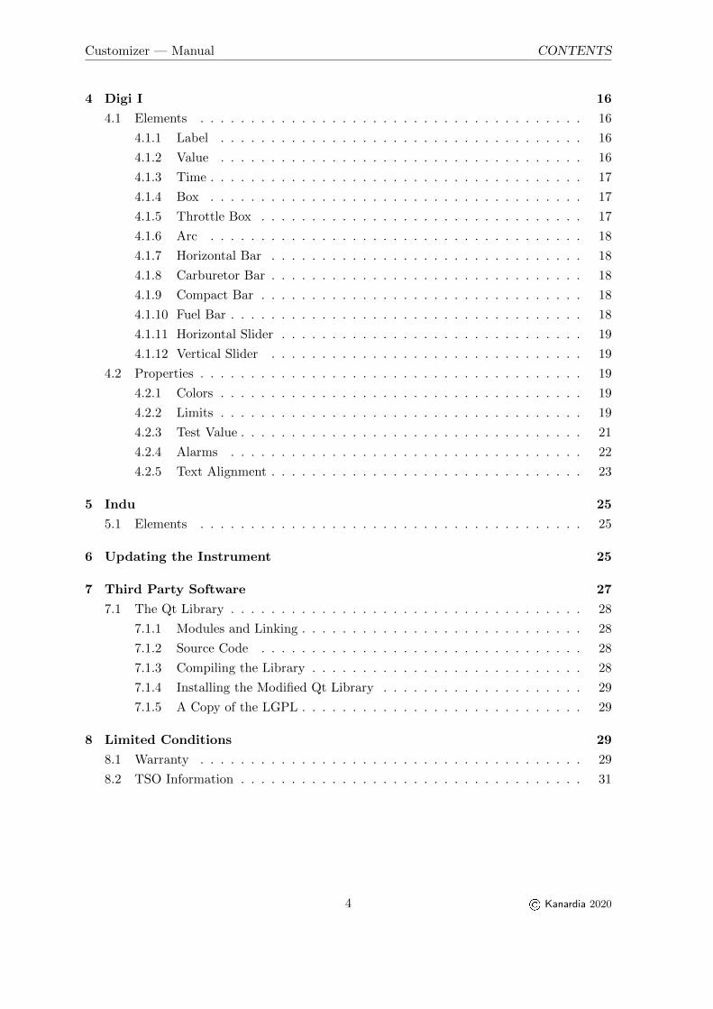
Contents
1 Introduction 5
1.1 General Description . . . . . . . . . . . . . . . . . . . . . . . . . . . . . . . . 5
1.2 Supported Instruments . . . . . . . . . . . . . . . . . . . . . . . . . . . . . . . 5
2 Installation 6
2.1 Download . . . . . . . . . . . . . . . . . . . . . . . . . . . . . . . . . . . . . . 6
2.2 Installation . . . . . . . . . . . . . . . . . . . . . . . . . . . . . . . . . . . . . 6
2.2.1 Linux . . . . . . . . . . . . . . . . . . . . . . . . . . . . . . . . . . . . 6
2.2.2 MacOS . . . . . . . . . . . . . . . . . . . . . . . . . . . . . . . . . . . 6
2.2.3 Windows . . . . . . . . . . . . . . . . . . . . . . . . . . . . . . . . . . 7
2.3 Uninstall . . . . . . . . . . . . . . . . . . . . . . . . . . . . . . . . . . . . . . 8
2.3.1 Linux . . . . . . . . . . . . . . . . . . . . . . . . . . . . . . . . . . . . 8
2.3.2 MacOS . . . . . . . . . . . . . . . . . . . . . . . . . . . . . . . . . . . 9
2.3.3 Windows . . . . . . . . . . . . . . . . . . . . . . . . . . . . . . . . . . 9
2.4 Support . . . . . . . . . . . . . . . . . . . . . . . . . . . . . . . . . . . . . . . 9
3 Instructions 10
3.1 Toolbar . . . . . . . . . . . . . . . . . . . . . . . . . . . . . . . . . . . . . . . 10
3.1.1 New . . . . . . . . . . . . . . . . . . . . . . . . . . . . . . . . . . . . . 10
3.1.2 Open . . . . . . . . . . . . . . . . . . . . . . . . . . . . . . . . . . . . 10
3.1.3 Save & Save As . . . . . . . . . . . . . . . . . . . . . . . . . . . . . . . 10
3.1.4 Zoom Options . . . . . . . . . . . . . . . . . . . . . . . . . . . . . . . 11
3.1.5 Unit Settings . . . . . . . . . . . . . . . . . . . . . . . . . . . . . . . . 11
3.1.6 Screenshot . . . . . . . . . . . . . . . . . . . . . . . . . . . . . . . . . 11
3.1.7 Clear . . . . . . . . . . . . . . . . . . . . . . . . . . . . . . . . . . . . 11
3.1.8 Close . . . . . . . . . . . . . . . . . . . . . . . . . . . . . . . . . . . . 11
3.2 Layout . . . . . . . . . . . . . . . . . . . . . . . . . . . . . . . . . . . . . . . . 12
3.2.1 List of Elements . . . . . . . . . . . . . . . . . . . . . . . . . . . . . . 12
3.2.2 Design Area . . . . . . . . . . . . . . . . . . . . . . . . . . . . . . . . . 12
3.2.3 Tools . . . . . . . . . . . . . . . . . . . . . . . . . . . . . . . . . . . . 13
3.2.4 Table of Properties . . . . . . . . . . . . . . . . . . . . . . . . . . . . . 14
3.2.5 Engine Defaults . . . . . . . . . . . . . . . . . . . . . . . . . . . . . . . 15
3 © Kanardia 2020
Customizer — Manual CONTENTS
4 Digi I 16
4.1 Elements . . . . . . . . . . . . . . . . . . . . . . . . . . . . . . . . . . . . . . 16
4.1.1 Label . . . . . . . . . . . . . . . . . . . . . . . . . . . . . . . . . . . . 16
4.1.2 Value . . . . . . . . . . . . . . . . . . . . . . . . . . . . . . . . . . . . 16
4.1.3 Time . . . . . . . . . . . . . . . . . . . . . . . . . . . . . . . . . . . . . 17
4.1.4 Box . . . . . . . . . . . . . . . . . . . . . . . . . . . . . . . . . . . . . 17
4.1.5 Throttle Box . . . . . . . . . . . . . . . . . . . . . . . . . . . . . . . . 17
4.1.6 Arc . . . . . . . . . . . . . . . . . . . . . . . . . . . . . . . . . . . . . 18
4.1.7 Horizontal Bar . . . . . . . . . . . . . . . . . . . . . . . . . . . . . . . 18
4.1.8 Carburetor Bar . . . . . . . . . . . . . . . . . . . . . . . . . . . . . . . 18
4.1.9 Compact Bar . . . . . . . . . . . . . . . . . . . . . . . . . . . . . . . . 18
4.1.10 Fuel Bar . . . . . . . . . . . . . . . . . . . . . . . . . . . . . . . . . . . 18
4.1.11 Horizontal Slider . . . . . . . . . . . . . . . . . . . . . . . . . . . . . . 19
4.1.12 Vertical Slider . . . . . . . . . . . . . . . . . . . . . . . . . . . . . . . 19
4.2 Properties . . . . . . . . . . . . . . . . . . . . . . . . . . . . . . . . . . . . . . 19
4.2.1 Colors . . . . . . . . . . . . . . . . . . . . . . . . . . . . . . . . . . . . 19
4.2.2 Limits . . . . . . . . . . . . . . . . . . . . . . . . . . . . . . . . . . . . 19
4.2.3 Test Value . . . . . . . . . . . . . . . . . . . . . . . . . . . . . . . . . . 21
4.2.4 Alarms . . . . . . . . . . . . . . . . . . . . . . . . . . . . . . . . . . . 22
4.2.5 Text Alignment . . . . . . . . . . . . . . . . . . . . . . . . . . . . . . . 23
5 Indu 25
5.1 Elements . . . . . . . . . . . . . . . . . . . . . . . . . . . . . . . . . . . . . . 25
6 Updating the Instrument 25
7 Third Party Software 27
7.1 The Qt Library . . . . . . . . . . . . . . . . . . . . . . . . . . . . . . . . . . . 28
7.1.1 Modules and Linking . . . . . . . . . . . . . . . . . . . . . . . . . . . . 28
7.1.2 Source Code . . . . . . . . . . . . . . . . . . . . . . . . . . . . . . . . 28
7.1.3 Compiling the Library . . . . . . . . . . . . . . . . . . . . . . . . . . . 28
7.1.4 Installing the Modified Qt Library . . . . . . . . . . . . . . . . . . . . 29
7.1.5 A Copy of the LGPL . . . . . . . . . . . . . . . . . . . . . . . . . . . . 29
8 Limited Conditions 29
8.1 Warranty . . . . . . . . . . . . . . . . . . . . . . . . . . . . . . . . . . . . . . 29
8.2 TSO Information . . . . . . . . . . . . . . . . . . . . . . . . . . . . . . . . . . 31
4 © Kanardia 2020

Customizer — Manual 1. Introduction
1 Introduction
First of all, we would like to thank you for choosing Kanardia.
Customizer offers a quick way to customize your Instruments’ display. This manual describesthe installation process, instructions for use and connection to your device.
Customizer is used in combination with BLU and KANJA. They are necessary for datatransfer from the PC on which you are running Customizer to your Kanardia instrument.
1.1 General Description
Customizer is a desktop application for our instruments’1 display customization. It lets theuser choose what information you wish to display and how you wish to display it. It is simpleand intuitive to use.
Customizer features more than 40 engine functions and a dozen different graphical elementsfor function values display. You can choose the units you prefer, customize value limits andset alarm warnings. And most importantly, your display layout is completely up to you.
1.2 Supported Instruments
The following table shows supported instruments.
Version Date Instruments
1.0 March 2020 Digi I, Indu Round Indicators
Table 1: Currently supported instruments
1 Instruments available for customization can be found in Table 1.
5 © Kanardia 2020

Customizer — Manual 2. Installation
2 Installation
Customizer is supported for Linux, macOS and Windows.
2.1 Download
Go to www.kanardia.eu/customizer and find your operating system. Click the link todownload the application to your computer.
2.2 Installation
2.2.1 Linux
1. Unzip the archive
2. Move the Customizer.AppImage file to your Desktop or to another folder of your choice
3. Right-Click on the Customizer icon, select Properties
4. Open the Permissions tab
5. Make sure that ’Is executable’ checkbox is checked
6. Select OK to close the window
No other installation steps are required. Double click (or single, depending on your OSsettings) to run.
2.2.2 MacOS
1. Unzip the archive
2. Open the Installer.dmg file. You will find the Customizer app and a link to theApplications folder inside
3. Drag Customizer to Applications folder
4. Close the installer and eject it
6 © Kanardia 2020

Customizer — Manual 2.2 Installation
5. Open Launchpad, find Customizer and run it
6. If a dialog pops-up, asking for permission to run, click Open
2.2.3 Windows
1. Unzip the archive
2. Run the CustomizerInstaller.exe
3. Select the location where you want the application’s data to be installed
4. Select all components and a shortcut location
5. Click Install and wait for the installation to complete
6. Click Finish
7 © Kanardia 2020

Customizer — Manual 2.3 Uninstall
After completing the installation, find Customizer in the Start menu or on your Desktop.
In case that Windows Defender prevents you from running the application. Follow thesesimple steps:
2.3 Uninstall
2.3.1 Linux
Delete Customizer.AppImage:
8 © Kanardia 2020

Customizer — Manual 2.4 Support
1. Left-click on the application icon to select it
2. Press the DEL key on your keyboard
or
1. Right-click on the application icon
2. Select Move to Trash option
2.3.2 MacOS
1. Open Finder
2. Find the Applications subfolder
3. Select Customizer
4. Press the (CMD + ) Backspace key on your keyboard
2.3.3 Windows
1. Open Control Panel
2. Under section Programs click Uninstall a program
3. Find Customizer on the list
4. Select it and click Uninstall
5. Select ’Remove all components’.
6. To confirm, click Uninstall
2.4 Support
For help, feedback or in case of application errors, please contact: [email protected]
9 © Kanardia 2020

Customizer — Manual 3. Instructions
3 Instructions
3.1 Toolbar
Figure 1 illustrates the application toolbar with available actions. Action explanations follow.
Figure 1: Customizer toolbar actions
3.1.1 New
This action creates a new project. In the dialog that opens, input the name of the project.Then, select the instrument you wish to customize and that instrument’s model. Click OK toconfirm your choices. A blank project is opened and ready for you to start customizing.
Figure 2: New Project dialog
3.1.2 Open
Opens a generic file dialog. Find a project you wish to import and click OPEN. All projectfiles should have a .iml extension.
3.1.3 Save & Save As
Save your project information to an external file. When prompted by the dialog, input thefile name and location. Click Save.
Figure 3: Save Project dialog
Program information is formatted and written into a YourFileName.iml file. This file canthen be used to modify your instrument display or it can again be opened by Customizer.
10 © Kanardia 2020
Customizer — Manual 3.1 Toolbar
3.1.4 Zoom Options
There are three options for scaling the screen. Zoom-In, Zoom-Out and Default-Zoom. Thesefunctionalities are for ease of use in the Customizer application and will not affect scaling onyour actual device.
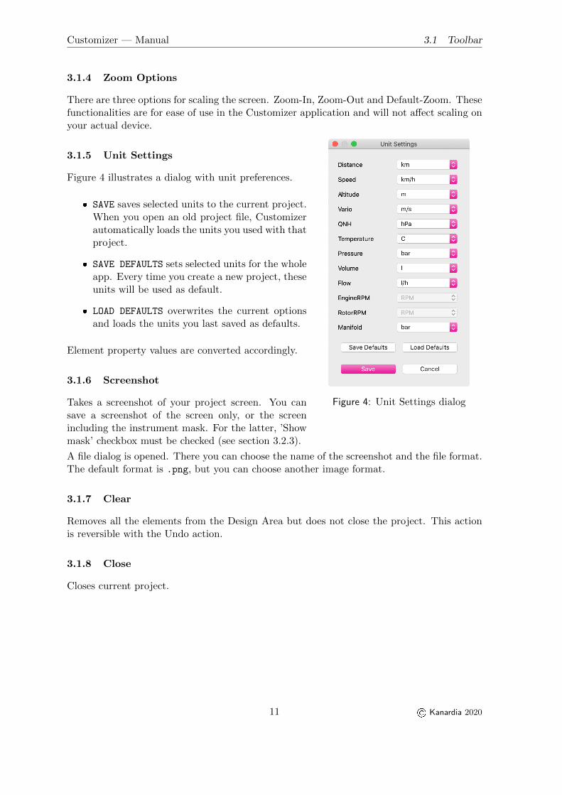
3.1.5 Unit Settings
Figure 4: Unit Settings dialog
Figure 4 illustrates a dialog with unit preferences.
� SAVE saves selected units to the current project.When you open an old project file, Customizerautomatically loads the units you used with thatproject.
� SAVE DEFAULTS sets selected units for the wholeapp. Every time you create a new project, theseunits will be used as default.
� LOAD DEFAULTS overwrites the current optionsand loads the units you last saved as defaults.
Element property values are converted accordingly.
3.1.6 Screenshot
Takes a screenshot of your project screen. You cansave a screenshot of the screen only, or the screenincluding the instrument mask. For the latter, ’Showmask’ checkbox must be checked (see section 3.2.3).
A file dialog is opened. There you can choose the name of the screenshot and the file format.The default format is .png, but you can choose another image format.
3.1.7 Clear
Removes all the elements from the Design Area but does not close the project. This actionis reversible with the Undo action.
3.1.8 Close
Closes current project.
11 © Kanardia 2020

Customizer — Manual 3.2 Layout
3.2 Layout
Figure 5 illustrates a general application layout.
Figure 5: General layout of the application
1O List of Elements 2O Design Area
3O Tools
4O Table of Properties
5O Engine Defaults
3.2.1 List of Elements
A list of all elements for your selected instrument and model.
To add a new element to your project, drag it from the list to the design area. Drop itwhererever you want. Alternatively, double-click an element and it will be added to thecenter of the screen.
3.2.2 Design Area
A black screen is centered in the design area and is a representation of your device’s display.Elements can be added to the screen from the list of elements.
Working with the elements in the design area:
� Selection
Left-Click an element in the design area to select it. Select multiple elements with acombination of CTRL2 and Left-Click or with mouse-drag selection. Selected elementsare identified with a dashed border.
2 On macOS keyboards use the CMD key instead.
12 © Kanardia 2020

Customizer — Manual 3.2 Layout
� Boundaries
Elements not fully positioned inside the screen are colored red. Out of bounds elementswill not be displayed on your device, but can be saved as a part of your project.
� Positioning
Selected elements can be moved around in various ways:
– Mouse drag
– Keyboard arrows (1 px)
– CTRL2+ Keyboard arrows (10 px)
– from Table of properties (X and Y coordinates)
– from Tools (alignment)
� Deletion
To remove selected element(s) from the Design Area use DELETE or BACKSPACE keys onyour keyboard. Alternatively, drag your selection out of the Design Area.
� Duplication
The keyboard combination CTRL2+ D duplicates selected elements, including their prop-erties.
� Undo & Redo
To undo any element changes use CTRL2+ Z. Then use CTRL2+ SHIFT + Z to redo them.Alternatively, use the toolbar Undo & Redo buttons.
Zoom3 Zoom can be achieved with a combination of CTRL key & mouse wheel or touchpadpinch for MacOS users. Another option is to use zoom actions from the toolbar.
3.2.3 Tools
� Alignment
Align edges of selected elements. If only one element is selected, it is aligned to theedge of the screen.
Top Bottom Left Right
� Centering
Centering is split into two groups:
(a) Center selected elements relative to each other. Found under the ’Align’ section.
(b) Center selected elements relative to the screen. Found under the ’Center to screen’section.
Checking the ’Treat selection as group’ checkbox: Treats the whole selection as one andcenters it without compromising the alignments between selected elements themselves.
13 © Kanardia 2020

Customizer — Manual 3.2 Layout
Vertical HorizontalCenter Center
� Distribution
Possible for three or more selected elements. Rearranges selection so that vertical orhorizontal gaps between subsequent elements are all equal.
Vertical HorizontalDistribution Distribution
� Grid3
Grid is a visual helper for the user. Choose how many vertical and how many horizontallines you wish to see. Maximum number of grid lines depends on the screen size of theinstrument. Uncheck the checkbox to hide the grid.
� Mask
The ’Show mask’ checkbox toggles betwen displaying and hiding the instrument mask.In some instruments, the screen is partialy obscured by the instrument’s casing. In thatcase, the Mask tool is useful for checking that all elements are visible.
Figure 6: Indu 80 screenshot with and without mask
If ’Show mask’ is checked when taking a screenshot, the mask will be included in thesaved picture. Examples of screenshots are shown in Figure 6.
3.2.4 Table of Properties
A table of properties for the selected element.
When more than one element is selected, the table is shown only if all selected elements areof the same type. (For example - 3 Horizontal Bars.)
3 For customizing purposes only, it has no effect on your instrument’s actual display
14 © Kanardia 2020

Customizer — Manual 3.2 Layout
Modifiying a property value when multiple items are selected, updates this property forthe whole selection. If a property value differs for any of the selected elements, *VARIOUS*keyword is shown as a placeholder.
Here is a list with some generic properties and an explanation of their functionalities.
� FUNCTION Gives the element its main function. For example: RPM, fuel pressure,oil temperature, CHT, ...
� X, Y Set element’s coordinates. The point (X,Y) represents the top left corner of theelement. (0,0) is the top left corner of the instrument’s screen.
� TEST VALUE Numeric input for the selected function value.3 Uses units set in theUnit Settings dialog.
� LABEL Text input.
� FONT SIZE Changes size of the label or the value.
Other properties are element specific and will be explained in more detail in the next sections.
Property Validation
Some of the properties are additionally validated by the application. An orange banner isshown at the right bottom corner of the Customizer window.
Figure 7: Validation banner example
Messages in the banner list element’s invalid properties and explanations of the problems.An example banner is illustrated in Figure 7.
To indicate elements with validation problems, a triangular exclamation icon is posi-tioned over them.
To hide the banner and the icon, resolve the mentioned problems.
Validation messages are of informative nature and will be ignored when saving your project.
3.2.5 Engine Defaults
Engine defaults offer you a quick way to initialize selected elements’ properties. The defaultsare an unofficial collection of data for some of the more common engines.
The data you get depends on:
� element’s function (set from the table of properties) and
� selected engine type (see Figure 8).
15 © Kanardia 2020

Customizer — Manual 4. Digi I
Figure 8: Engine type selection
Figure 9: Message banner example
Pressing the Load defaults button updates properties of all selected elements. Changes canbe seen in the table of properties for each individual element.
Some of Function - Engine type combinations may not have any predefined values. Inwhich case, a message ’No data found.’ is displayed.
Updated properties can be some or all of the following:
� Yellow Low
� Yellow High
� Green Low
� Green High
� Test Value
� Low End
� High End
It is important to note that these values are unofficial and may contain irregularities. Acareful revision is advised.
4 Digi I
Digi I is an engine information system. This section describes its elements and their Proper-ties.
4.1 Elements
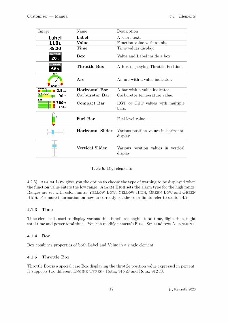
Table 5 illustrates Digi elements, each with a short description. Images are not in scale. Amore detailed overview follows.
4.1.1 Label
Label is a short text with a 15 character limit. No special characters are allowed. Font Sizeoptions vary from tiny to normal.
4.1.2 Value
Value is a simple way to display a function value. There are more than 40 Functions tochoose from. Units used are those set in the Unit Settings dialog. Five Font Size optionsranging from tiny to huge. Alignment property changes text alignment (more in section
16 © Kanardia 2020
Customizer — Manual 4.1 Elements
Image Name Description
Label A short text.
Value Function value with a unit.
Time Time values display.
Box Value and Label inside a box.
Throttle Box A Box displaying Throttle Position.
Arc An arc with a value indicator.
Horizontal Bar A bar with a value indicator.
Carburetor Bar Carburetor temperature value.
Compact Bar EGT or CHT values with multiplebars.
Fuel Bar Fuel level value.
Horizontal Slider Various position values in horizontaldisplay.
Vertical Slider Various position values in verticaldisplay.
Table 5: Digi elements
4.2.5). Alarm Low gives you the option to choose the type of warning to be displayed whenthe function value enters the low range. Alarm High sets the alarm type for the high range.Ranges are set with color limits: Yellow Low, Yellow High, Green Low and GreenHigh. For more information on how to correctly set the color limits refer to section 4.2.
4.1.3 Time
Time element is used to display various time functions: engine total time, flight time, flighttotal time and power total time . You can modify element’s Font Size and text Alignment.
4.1.4 Box
Box combines properties of both Label and Value in a single element.
4.1.5 Throttle Box
Throttle Box is a special case Box displaying the throttle position value expressed in percent.It supports two different Engine Types - Rotax 915 iS and Rotax 912 iS.
17 © Kanardia 2020

Customizer — Manual 4.1 Elements
4.1.6 Arc
Arc adds a graphic display of the function value to the more basic Label and numeric TestValue. Properties Low End and High End set different combinations of color ranges. Theformer for the left half of the arc and the latter for the right half. Ranges are set with colorlimits: Yellow Low, Yellow High, Green Low and Green High. Alarm Low andAlarm High properties set the warning type for function values in low and high rangesrespectively. The indicator’s position is an interpolation of the Test Value and the colorlimits for the chosen color options.4 For more information about colors, limits and alarmsrefer to section 4.2.
4.1.7 Horizontal Bar
Horizontal Bar has mostly the same properties as the Arc element. Function selection offersa few more options and the Low End and High End properties obviously refer to the leftand right halves of the bar. The indicator’s position is calculated the same way as Arc’s. Formore information about colors, limits and alarms refer to section 4.2.
4.1.8 Carburetor Bar
Carburetor Bar is a special case Horizontal Bar for displaying Carburetor Temperature. Itfeatures a Green-Yellow-Green colored bar. Color limits for Carburetor bar are distributeddifferently to the ones in the Horizontal Bar so please refer to section 4.2.2 for a moredetailed color limit setting instruction. As opposed to Horizontal Bar, it does not haveAlarm properties. When function output (Test Value in Customizer) enters the yellowrange, the displayed value turns yellow.
4.1.9 Compact Bar
Compact Bar is an element for displaying EGT and CHT values. Property Count sets thenumber of bars with options from 2 to 6. If Count is set to 4 or more, the element displaystwo values. The one on top shows the maximum of all bar values and the other one showsthe minimum. The Customizer application displays Test Value for both.3 The indicator’sposition is an interpolation of the Test Value and the color limits for the chosen coloroptions.4
4.1.10 Fuel Bar
Fuel Bar has two Fuel Level Functions and a property for the maximum tank Capacity.The triangular indicator’s position is an interpolation of the Test Value relative to thegiven Green Low, Yellow Low and Capacity values. Alarm Low sets a warning typefor the indicator in the red zone.
4 See table 6 for terminology explanation
18 © Kanardia 2020

Customizer — Manual 4.2 Properties
4.1.11 Horizontal Slider
Horizontal Slider is an element for displaying Pitch Trim, Throttle, Flaps and Roll Trimpositions expressed in ranges -1 to 1 or 0 to 1. See section 4.2.3 for more information aboutslider’s functions and their values. For Digi display compatibility the Horizontal Slider has a5px offset to the screen’s left edge.
4.1.12 Vertical Slider
Vertical Slider has the exact same functionalities as the Horizontal Slider. For Digi displaycompatibility the Vertical Slider has a 5px offset to the screen’s top edge.
4.2 Properties
4.2.1 Colors
[ Arc, Horizontal Bar, Carburetor Bar, Compact Bar ]
Elements from this section are graphically split into two parts – the low and the high end.
These are the color options from the Low End dropdown menu:
� Green
� Red-Green
� Yellow-Green
� Red-Yellow-Green
High End has the same options, just mirrored. Combining both color sections gives you 16possible color combinations.
Carburetor Bar element is a special case with only one color combination:
� Green-Yellow-Green
4.2.2 Limits
[ Value, Box, Arc, Horizontal Bar, Carburetor Bar, Compact Bar, Fuel Bar ]
Limits are values in function’s units that tell us the boundaries of different color zones. Theydo not change the graphics of the bars (or arcs).5 Graphically, the color ratios are fixed.
5 Fuel Bar is an exception to this rule. See Figure 14 for more information.
19 © Kanardia 2020
Customizer — Manual 4.2 Properties
Color Sections Color Options Color Limits
Low End Green (G) Yellow Low (YL)High End Red-Green (RG) Yellow High (YH)
Yellow-Green (YG) Green Low (GL)Red-Yellow-Green (RYG) Green High (GH)Green-Yellow-Red (GYR)
Green-Yellow (GY)Green-Red (GR)
Green-Yellow-Green (GYG)
Table 6: Terminology
Generally, there are four color limits for each element (see Table 6, ’Color Limits’ header).Rules for setting these values can depend on Low End & High End selections and/orelement’s Type.
Value and Box elements do not have Low End and High End properties, and no visualcolor representations. They still have the option to set the limits as the latter influence alarmbehaviour.
Color limits use units of the selected Function property. Unit changes can be made fromthe unit settings section in the toolbar.
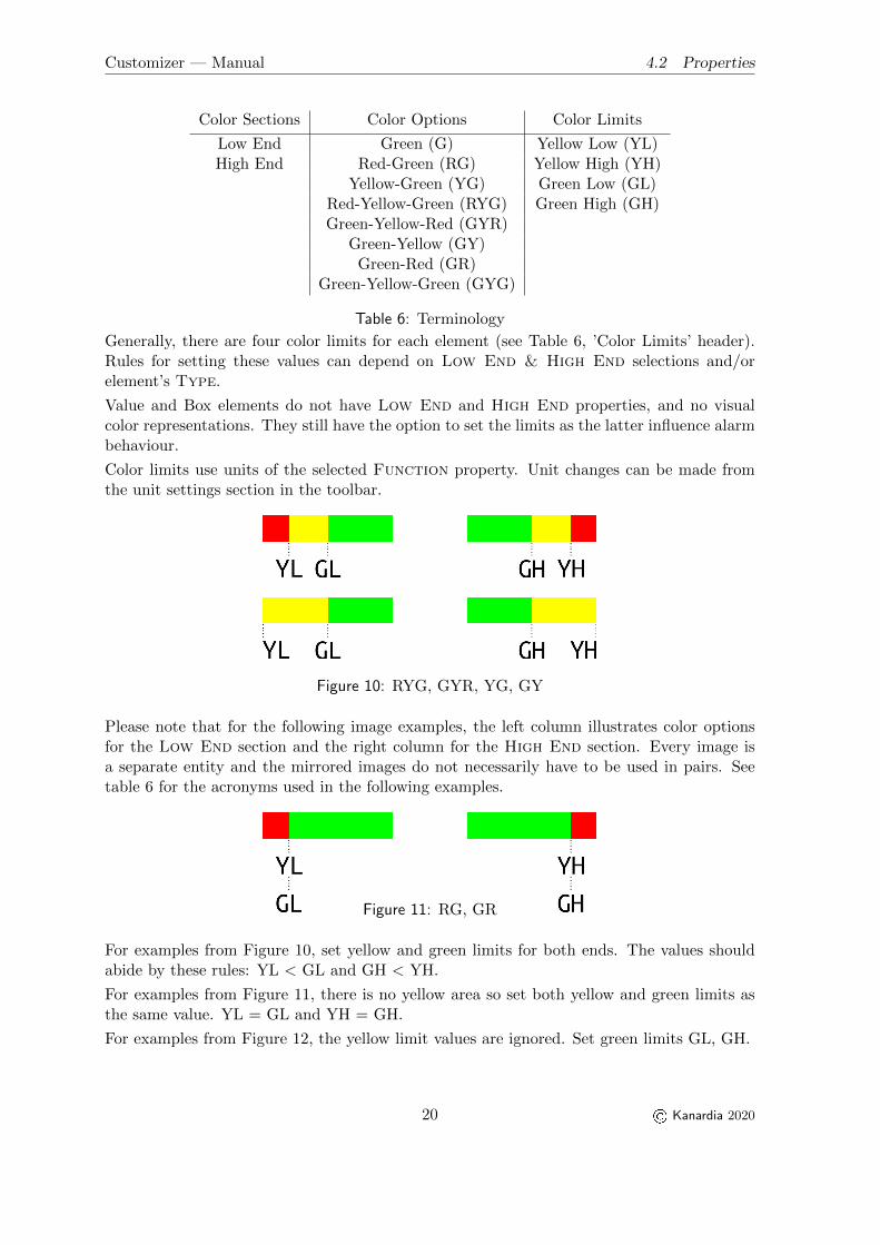
Figure 10: RYG, GYR, YG, GY
Please note that for the following image examples, the left column illustrates color optionsfor the Low End section and the right column for the High End section. Every image isa separate entity and the mirrored images do not necessarily have to be used in pairs. Seetable 6 for the acronyms used in the following examples.
Figure 11: RG, GR
For examples from Figure 10, set yellow and green limits for both ends. The values shouldabide by these rules: YL < GL and GH < YH.
For examples from Figure 11, there is no yellow area so set both yellow and green limits asthe same value. YL = GL and YH = GH.
For examples from Figure 12, the yellow limit values are ignored. Set green limits GL, GH.
20 © Kanardia 2020
Customizer — Manual 4.2 Properties
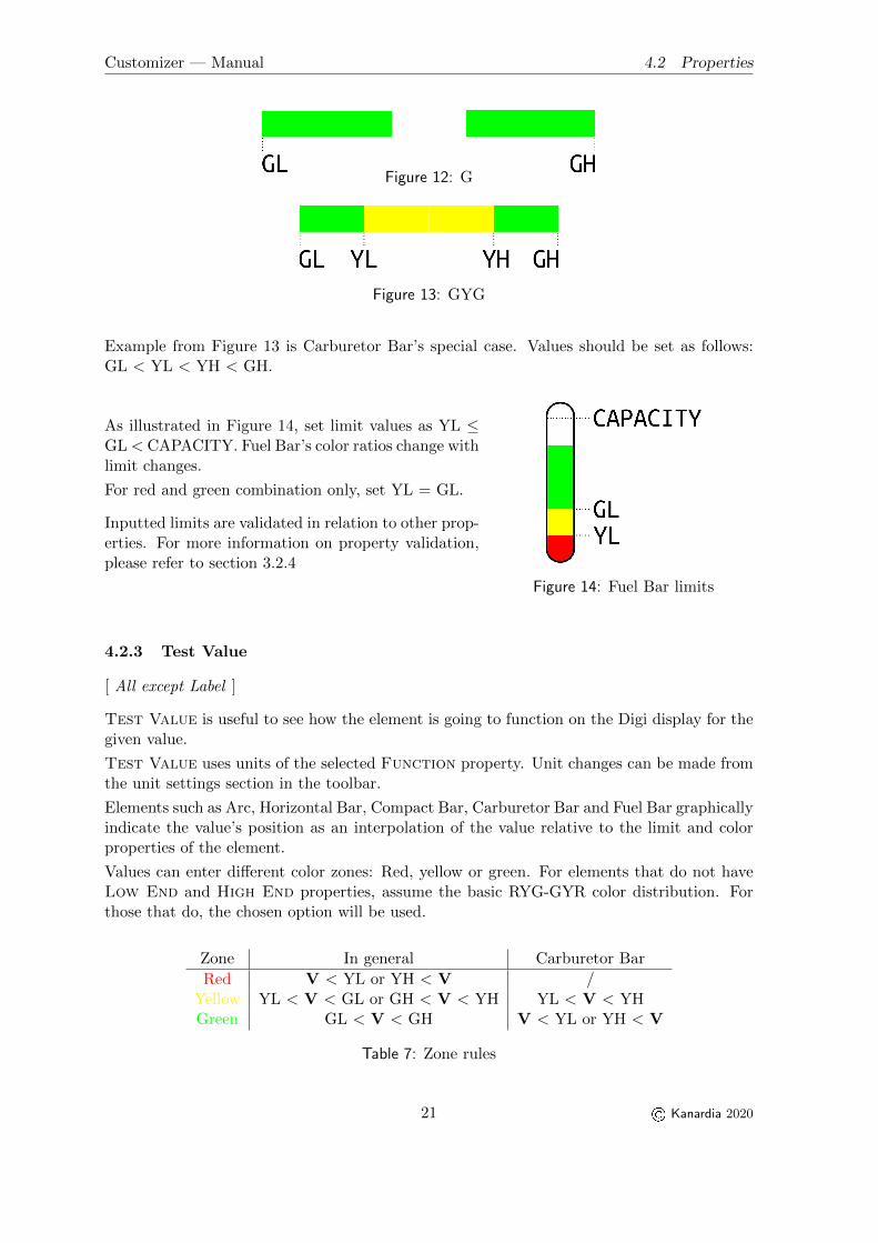
Figure 12: G
Figure 13: GYG
Example from Figure 13 is Carburetor Bar’s special case. Values should be set as follows:GL < YL < YH < GH.
Figure 14: Fuel Bar limits
As illustrated in Figure 14, set limit values as YL ≤GL < CAPACITY. Fuel Bar’s color ratios change withlimit changes.
For red and green combination only, set YL = GL.
Inputted limits are validated in relation to other prop-erties. For more information on property validation,please refer to section 3.2.4
4.2.3 Test Value
[ All except Label ]
Test Value is useful to see how the element is going to function on the Digi display for thegiven value.
Test Value uses units of the selected Function property. Unit changes can be made fromthe unit settings section in the toolbar.
Elements such as Arc, Horizontal Bar, Compact Bar, Carburetor Bar and Fuel Bar graphicallyindicate the value’s position as an interpolation of the value relative to the limit and colorproperties of the element.
Values can enter different color zones: Red, yellow or green. For elements that do not haveLow End and High End properties, assume the basic RYG-GYR color distribution. Forthose that do, the chosen option will be used.
Zone In general Carburetor Bar
Red V < YL or YH < V /Yellow YL < V < GL or GH < V < YH YL < V < YHGreen GL < V < GH V < YL or YH < V
Table 7: Zone rules
21 © Kanardia 2020

Customizer — Manual 4.2 Properties
See Table 7 for zone rules. Read ’V’ as (Test) Value.
Depending on the Alarm properties of the element, the value entering a different zone maytrigger a warning. More in section 4.2.4.
Figure 15: Pitch
Horizontal and Vertical Sliders do not have any color,limit or alarm properties. For Sliders, values are ex-pressed in ratios as evident in Figures 15, 17 and 16.
Notice Roll and Pitch trim functions ratio distributionis different to the one of Throttle and Flaps. Theformer span from -1.0 to 1.0 and the latter from 0.0to 1.0.
Pictured are recommended slider types for different functions and their value interpretations.
Figure 16: Throttle and Flaps Figure 17: Roll trim
4.2.4 Alarms
[ Value, Box, Arc, Horizontal Bar, Carburetor Bar, Compact Bar, Fuel Bar ]
Alarm Low sets the alarm type for the low end zone. Alarm High sets the alarm type forthe high end zone.
There are three alarm types:
� None Alarm is disabled
� Warning Alarm is enabled
� Active Engine Warning Alarm is enabled only when the engine is active
Warnings:
Alarm Low enabled with value in the low end red zone.6
Alarm High enabled with value in the high end red zone.
Visual effects:
6 Fuel Bar displays LOW warning from both red and yellow zones.
22 © Kanardia 2020

Customizer — Manual 4.2 Properties
For values in yellow zones of the enabled alarms.
There are no visual effects for values in the green zones.
Alarm warnings are only displayed on Digi for the actual function values. Warnings are notshown in Customizer with Test Values.
4.2.5 Text Alignment
[ Value ]
The width of the Value element depends on the width of its digits.
As the numeric value changes, the width of the element changes as well. If aligned incorrectly,a wider element can en up positioned partly off the screen. Using the Text Alignmentproperty, you can avoid these kinds of out of bounds problems.
Text Alignment works like an anchor. You can also think of it as a boundary that willnot be crossed when the value gets resized.
(a) Left (b) Center (c) Right
Figure 18: Value alignments
As illustrated in Figure 187, there are three types of alignments:
� Left,
� Center and
� Right.
Observe the position changes of the Value element when resized from 4 digits to 3.
a) For left alignment, the left border is the anchor. Widening or narrowing happens onthe right end.
b) For center alignment, the horizontal center of the element is the anchor. The resizinghappends on both ends of the element.
c) For right alignment, the right border is the anchor. Widening or narrowing happens onthe left end.
Example
In the following example, I will show you how to use text alignment on a Standard InduRound Indicator.
7 Orange line represents the alignment anchor.
23 © Kanardia 2020

Customizer — Manual 4.2 Properties
Starting layout
Step 1: First, I added some elements to the screen. In this case, Idecided to have the Value element positioned to the right edge. Thecurrent value is 90 km/h and the default text alignment is Left.
When the value changes, I do not want the element to either moveoff screen or to move away from the edge. To achieve that, I needto set the correct Text Alignment option.
Incorrect alignment aftervalue change
Step 2: I changed the Test Value to 100 km/h, to see thebehavior of the Left alignment.
The element got wider. Because the left border is the anchor,the right end widened. It is now hanging off of the screen. Thisis clearly not the way I want my display to look like.
I go back to beginning and set the value to 90 km/h. Thedisplay is the same as in the starting layout.
Step 3: Let’s see the behaviour, if I change the alignment toRight, then set the value to 100 km/h again.
Correct alignment aftervalue change
The position is correctly displayed. The element is still per-fectly aligned to the right edge of the screen.
24 © Kanardia 2020

Customizer — Manual 5. Indu
5 Indu
Our Indu Round Indicators come in two sizes: 57 mm and 80 mm. Because Indu 80 mmAltimeter has a unique mask shape, we have split model option into three categories:
1. 57 which contains every 57 mm Indu Round Indicator (including 57 mm Altimeter),
2. Altimeter 80 which contains the 80 mm Altimeter and
3. 80 which contains all the other 80 mm Indu Round Indicators.
All of these categories have the same set of elements with the same set of properties. TheList of elements is a subset of Digi I’s list. For more information on element functionalitiesplease refer to section 4.
5.1 Elements
Table 8 illustrates Indu elements, each with a short description. Images are not in scale.Element properties are described in more detail in section 4.1.
Image Name Description
Label A short text.
Value Function value with a unit.
Time Time values display.
Table 8: Indu elements
6 Updating the Instrument
When you finish customizing your screen layout, it’s time to update your instrument. Thissection describes how to do so.
What you’ll need:
� KANJA Android application,
� BLU,
� Kanardia instrument1,
25 © Kanardia 2020

Customizer — Manual 6. Updating the Instrument
� a USB cable (optional)
Figure 19 illustrates the three steps needed to update the instrument’s screen. Detailedinstructions follow bellow.
Figure 19: Data transfer steps
If this is your first time using Kanja, please refer to our Blu & Kanja User Manual for instal-lation instructions and user guide. You can find the manual on our website www.kanardia.euunder Digi->Manuals or under Support->Manuals.
In the next steps we assume you have Kanja downloaded on your Android device and that itis updated to the latest version. Also, that your Kanardia instrument is powered on and hasa BLU inserted into one of the ports.
1. Save your project. A *.iml file is created with all your data. We will be usingYourFileName.iml as an example.
2. Transfer the YourFileName.iml file to your Android. A few options on how to do so:
� e-mail On your computer, write a new email withYourFileName.iml as an attachment. Send it to the email you are using on theAndroid device (it can be the same one you are using on your computer) or justsave the email as a draft to access it later. On the Android device open the emailand download the YourFileName.iml attachment. In most cases the file will besaved in the Downloads folder on your device.
� cloud-sharing Open your preferred cloud service (Google Drive, DropBox, iCloud,...) with a browser or an application. Upload YourFileName.iml to it. Open thatsame cloud service on your Android device and download the file. In most casesthe file will be saved in the Downloads folder on your device.
� USB cable Connect your Android device to yourcomputer with the USB cable for file transfer. When prompted, open the foldercontaining your Android device files. Copy YourFileName.iml from the a direc-tory on your computer to a directory on your Android. The fastest option is tofind the Downloads directory on your device and copy the file there.
26 © Kanardia 2020

Customizer — Manual 7. Third Party Software
3. (a) Open Kanja and connect it to your Kanardia instrument that supports Customizerfiles.1 Refer to the Blu & Kanja User Manual for help.
(b) Under Units select the instrument.
(c) From the menu, open Screen Custom. Listed are the files saved in the Downloadsfolder on your device.
(d) Select the file you wish to transfer to your instrument.
Finally, your instrument’s screen should display the new layout you created using Customizer.
7 Third Party Software
This section has nothing to do with the usage of the Customizer. You can skip it completelyif you are not interested in software development and licensing issues.
27 © Kanardia 2020

Customizer — Manual 7.1 The Qt Library
7.1 The Qt Library
The Customizer software was developed with the help of the Qt Library, which is a productof The Qt Company . The library offers several licenses. One of them is the LGPLv3 license,which we chose for the Customizer.
Choosing this license gives us some obligations. They are partly fulfilled by Customizer,partly by this manual and partly by our web server. The following subsections give insightinto the details.
7.1.1 Modules and Linking
Customizer is using dynamic linking with the following libraries from the Qt library bundle:libQt5Core, libQt5Gui, libQt5Svg, libQt5Widgets and libQt5Xml.
7.1.2 Source Code
The source code of the Qt Library used with Customizer can be obtained from our website:
1. Use your browser and open https://www.kanardia.eu.
2. Select SUPPORT|Software from the menu on the top right side. A list of various softwarebundles will appear.
3. Select QtSource Customizer to download the Qt Library source code.
7.1.3 Compiling the Library
Once the library was downloaded, use the following steps to build the library binaries on yourcomputer.
� Compiling on Linux or macOS:
1. Extract QtSource Customizer.zip.
2. Enter folder qtbase/.
3. Configure Qt with# ./configure -opensource -gui -widgets -no-xcb
4. Compile it with:# make
� Compiling on Windows:
1. Extract QtSource Customizer.zip.
2. Enter folder qtbase/.
3. Configure Qt with# configure -opensource -gui -widgets -platform win32-g++
4. Compile it with:# mingw32-make
28 © Kanardia 2020

Customizer — Manual 8. Limited Conditions
7.1.4 Installing the Modified Qt Library
The LGPLv3 license allows you to freely adapt and change the source code according to yourneeds.
1. Use your favorite source code editor to edit and modify the Qt Library source code.
2. Compile the changes (see section 7.1.3) and produce the binaries.
3. Copy binaries to the Customizer installation folder. This will overwrite existing li-braries.
4. Close any running Customizer application.
5. Rerun Customizer. The new libraries will be used.
7.1.5 A Copy of the LGPL
A copy of the GNU Lesser General Public License is stored in Customizer. How to access it,is described next:
1. Select About from the Toolbar
2. In the dialog that appears, open the LGPL tab
8 Limited Conditions
Although a great care was taken during the design, production, storage and handling, it mayhappen that the Product will be defective in some way. Please read the following sectionsabout the warranty and the limited operation to get more information about the subject.
8.1 Warranty
Kanardia d.o.o. warrants the Product manufactured by it against defects in material andworkmanship for a period of twenty-four (24) months from retail purchase.
Warranty Coverage
Kanardia’s warranty obligations are limited to the terms set forth below:
Kanardia d.o.o. warrants the Kanardia-branded hardware product will conform to the pub-lished specification when under normal use for a period of twenty-four months (24) from thedate of retail purchase by the original end-user purchaser (”Warranty Period”). If a hardwaredefect arises and a valid claim is received within the Warranty Period, at its option and as thesole and exclusive remedy available to Purchaser, Kanardia will either (1) repair the hardwaredefect at no charge, using new or refurbished replacement parts, or (2) exchange the productwith a product that is new or which has been manufactured from new or serviceable usedparts and is at least functionally equivalent to the original product, or, at its option, if (1) or(2) is not possible (as determined by Kanarida in its sole discretion), (3) refund the purchaseprice of the product. When a refund is given, the product for which the refund is providedmust be returned to Kanardia and becomes Kanardia’s property.
29 © Kanardia 2020

Customizer — Manual 8.1 Warranty
Exclusions and Limitations
This Limited Warranty applies only to hardware products manufactured by or for Kanardiathat have the ”Kanardia” trademark, trade name, or logo affixed to them at the time of man-ufacture by Kanardia. The Limited Warranty does not apply to any non-Kanardia hardwareproducts or any software, even if packaged or sold with Kanardia hardware. Manufacturers,suppliers, or publishers, other than Kanardia, may provide their own warranties to the Pur-chaser, but Kanarida and its distributors provide their products AS IS, without warranty ofany kind.
Software distributed by Kanardia (with or without the Kanardia’s brand name including,but not limited to system software) is not covered under this Limited Warranty. Refer to thelicensing agreement accompanying such software for details of your rights with respect to itsuse.
This warranty does not apply: (a) to damage caused by use with non-Kanardia products;(b) to damage caused by accident, abuse, misuse, flood, fire, earthquake or other externalcauses; (c) to damage caused by operating the product outside the permitted or intended usesdescribed by Kanardia; (d) to damage caused by service (including upgrades and expansions)performed by anyone who is not a representative of Kanardia or an Kanarida AuthorizedReseller; (e) to a product or part that has been modified to significantly alter functionalityor capability without the written permission of Kanardia; (f) to consumable parts, such asbatteries, unless damage has occurred due to a defect in materials or workmanship; or (g) ifany Kanardia serial number has been removed, altered or defaced.
To the extent permitted by applicable law, this warranty and remedies set forth above areexclusive and in lieu of all other warranties, remedies and conditions, whether oral or written,statutory, express or implied, including, without limitation, warranties of merchantability,fitness for a particular purpose, non-infringement, and any warranties against hidden orlatent defects. If Kanardia cannot lawfully disclaim statutory or implied warranties then tothe extent permitted by law, all such warranties shall be limited in duration to the durationof this express warranty and to repair or replacement service as determined by Kanardiain its sole discretion. Kanardia does not warrant that the operation of the product will beuninterrupted or error-free. Kanardia is not responsible for damage arising from failure tofollow instructions relating to the product’s use. No Kanardia reseller, agent, or employee isauthorized to make any modification, extension, or addition to this warranty, and if any ofthe foregoing are made, they are void with respect to Kanardia.
Limitation of Liability
To the extent permitted by applicable law, Kanardia is not responsible for indirect, special,incidental or consequential damages resulting from any breach of warranty or condition, orunder any other legal theory, including but not limited to loss of use; loss of revenue; loss ofactual or anticipated profits (including loss of profits on contracts); loss of the use of money;loss of anticipated savings; loss of business; loss of opportunity; loss of goodwill; loss of repu-tation; loss of, damage to or corruption of data; or any other loss or damage howsoever causedincluding the replacement of equipment and property, any costs of recovering, programming,or reproducing any program or data stored or used with Kanardia products and any failureto maintain the confidentiality of data stored on the product. Under no circumstances willKanardia be liable for the provision of substitute goods or services. Kanardia disclaims any
30 © Kanardia 2020

Customizer — Manual 8.2 TSO Information
representation that it will be able to repair any product under this warranty or make a prod-uct exchange without risk to or loss of the programs or data. Some jurisdictions do not allowfor the limitation of liability for personal injury, or of incidental or consequential damages,so this limitation may not apply to you.
8.2 TSO Information — Limited Operation
This product is not TSO approved as a flight instrument. Therefore, the manufacturer willnot be held responsible for any damage caused by its use. The Kanardia is not responsible forany possible damage or destruction of any part on the airplane caused by default operationof instrument.
31 © Kanardia 2020