Customer Application Brief Oil & Gas Filtration in Tail...
4
Customer Application Brief Oil & Gas Filtration in Tail Gas Cleanup Units Introduction Refineries use various processes to reduce acid gases from process streams. In the amine sweetening process, acid gases are reduced from sour gas, and sent to the sulfur recovery unit, also called a Claus plant. Claus process technology, however, typically only provides about 96% sulfur recovery. In order to comply with emissions regulations, refineries often add a tail gas cleanup unit after the Claus plant to increase overall sulfur recovery to 99.9%. Filtration is required in the tail gas cleanup unit to protect process equipment and to maintain overall system efficiency. This Customer Application Brief (CAB) addresses the benefits of effective filtration. The Process The Claus plant recovers about 96% of total sulfur from the acid gas effluent created in the amine sweetening unit. The effluent from the Claus plant, commonly referred to as tail gas (a mixture of light ends and acid gases), is sent to the tail gas cleanup unit, where the acid gases – primarily hydrogen sulfide (H 2 S), sulfur dioxide (SO 2 ), carbonyl sulfide (COS), and carbon disulfide (CS 2 ) – are heated and mixed with hydrogen in the presence of a cobalt-molybdenum catalyst. This reaction reduces all sulfur compounds in the tail gas to H 2 S. The effluent from the reactor is then cooled in a quench column. The quench water serves to cool the stream to the appropriate temperature for amine contacting, and to absorb any residual SO 2 that breaks through the reactor. The cooled gas stream is then sent to the tail gas unit’s amine contactor to reduce any residual H 2 S. The treated tail gas is then sent to the thermal oxidizer, where any remaining sulfur compounds are converted to SO 2 . The tail gas/ SO 2 mixture is then flared to atmosphere. The rich amine is stripped of the H 2 S and recirculated back to the contactor. The stripped H 2 S is sent back to the Claus plant for reprocessing. Figure 1 — Tail Gas Cleanup Unit 2 Amine Contactor Flare Stripper Filter #1 Quench Column Filter #2 Filter #3 Filter #4 Cross Exchanger Tail Gas from Claus Plant To Claus Plant H Rich Amine Lean Amine Stripped H 2 S Carbon Bed
Transcript of Customer Application Brief Oil & Gas Filtration in Tail...

Customer Application Brief
Oil & Gas
Filtration in Tail Gas Cleanup UnitsIntroductionRefineries use various processes to reduce acid gases from process streams. In the amine sweetening process, acid gases are reduced from sour gas, and sent to the sulfur recovery unit, also called a Claus plant. Claus process technology, however, typically only provides about 96% sulfur recovery. In order to comply with emissions regulations, refineries often add a tail gas cleanup unit after the Claus plant to increase overall sulfur recovery to 99.9%. Filtration is required in the tail gas cleanup unit to protect process equipment and to maintain overall system efficiency. This Customer Application Brief (CAB) addresses the benefits of effective filtration.
The ProcessThe Claus plant recovers about 96% of total sulfur from the acid gas effluent created in the amine sweetening unit. The effluent from the Claus plant, commonly referred to as tail gas (a mixture of light ends and acid gases), is sent to the tail gas cleanup unit, where the acid gases – primarily hydrogen sulfide (H2S), sulfur dioxide (SO2), carbonyl sulfide (COS), and carbon disulfide (CS2) – are heated and mixed with hydrogen in the presence of a cobalt-molybdenum catalyst. This reaction reduces all sulfur compounds in the tail gas to H2S. The effluent from the reactor is then cooled in a quench column. The quench water serves to cool the stream to the appropriate temperature for amine contacting, and to absorb any residual SO2 that breaks through the reactor. The cooled gas stream is then sent to the tail gas unit’s amine contactor to reduce any residual H2S. The treated tail gas is then sent to the thermal oxidizer, where any remaining sulfur compounds are converted to SO2. The tail gas/SO2 mixture is then flared to atmosphere. The rich amine is stripped of the H2S and recirculated back to the contactor. The stripped H2S is sent back to the Claus plant for reprocessing.
Figure 1 — Tail Gas Cleanup Unit
CrossExchanger
2
Amin
eCo
ntac
tor
Flare
Strip
per
Filter #1
Quen
ch C
olum
n
Filter #2
Filter #3Filter #4
CrossExchanger
Tail Gasfrom Claus Plant
To Claus Plant
H
Rich Amine
Lean Amine
Stripped H2S
CarbonBed

The ProblemContamination in the tail gas cleanup unit can cause many problems, including:
Quench Column SectionHydrogen Blistering – Although the reactor ideally reduces all sulfur compounds, including SO2, to H2S, some trace quantities of SO2 may “break through.” The SO2 reacts with H2S in the quench water to form elemental sulfur. The sulfur must be filtered out to prevent sulfur deposits on the column and cooler internals. Unabated deposits of sulfur on process equipment internals can lead to hydrogen blistering, and can result in maintenance costs to clean equipment internal surfaces and lost revenues as the system is shut down for cleaning.
Amine Contacting SectionContactor Plugging – Solids deposited on the trays of the contactor can plug the bubble caps on the trays, resulting in higher gas velocities through the trays. Higher velocities will increase the tendency of the amine to foam and not allow the gas to come in full contact with the amine at the subsequent trays. If contact is missed at enough trays, ineffective absorption can take place. Solids deposition on the trays will also increase differential pressure, resulting in amine carryover and eventually a maintenance shutdown to clean the trays.
Heat Exchanger / Reboiler Fouling Solids deposited on the heat exchanger and reboiler tube surfaces cause poor heat transfer resulting in ineffective regeneration of the amine solution. As the reboiler tubes become fouled and ineffective regeneration occurs, operators typically increase heat to the reboiler to improve the regeneration process, which in turn results in higher energy usage. The tubes of the reboiler are not coated uniformly by the deposited solids and the additional heat to the reboiler causes “hot spots” to form. These hot spots, or points on the tubes where high temperatures exist, are sites where rapid degradation of the amine solution can occur. As amine degradation occurs, corrosion rates increase and the tendency of the amine to foam increases. As a result, amine carryover rates increase, maintenance costs are incurred to clean out the exchangers, and lost revenues occur as the system is shut down to complete the necessary repairs.
Carbon Bed Fouling Contaminants introduced into the carbon bed increase differential pressure across the bed, block access to the active sites of the carbon, and increase the tendency for amine to “channel” through the bed. The result is reduced absorptive capacity, resulting in frequent carbon bed regeneration or, in the worst case, premature replacement of the carbon bed.
Foaming Solids in the amine stabilize foaming that occurs by increasing the surface tension of the amine and making it more difficult for the individual foam “bubbles” to break. As previously described, if the foam is stable enough to prevent full contact at the next tray, ineffective absorption can occur. In addition, foaming results in high amine carryover rates and, therefore, high amine replacement costs.
The SolutionTo reduce contamination problems, 3M Purification Inc. recommends four stages of filtration for optimal performance of tail gas cleanup units.
1. Filter 1 – Quench water filtration. Five-micron 3M™ DF series is recommended to filter the elemental sulfur in the quench water loop to adequately protect the quench section process equipment from hydrogen blistering.
2. Filter 2 – Recirculating amine system. Ten-micron 3M™ 740 series or Betapure™ PK series filters are recommended, depending on existing plant configuration. Locating the filter in the rich line upstream of the heat exchanger will reduce solid contamination including iron sulfide and corrosion products. This helps protect both the heat exchanger and the stripper.
3. Filters 3 & 4 – Upstream and downstream of the carbon bed. Ten-micron 3M 740 series or Betapure PK series filters are recommended, depending on existing plant configuration. The carbon bed reduces entrained hydrocarbons and surface active compounds, reducing the tendency of the amine solution in the contactor to foam. Locating the filter upstream of
the carbon filter reduces carbon bed fouling. Downstream filters will help protect the contactor by reducing carbon fines that would otherwise be deposited on the column’s trays.
For Filter Position 1, 3M Purification recommends the 3M™ DF series filtration system. The unique design of the 3M DF series filter system can provide for up to 4 times more service life and 2 – 3 times more contaminant capture capacity than conventional bag filters translating into reduced change-out requirements.
Using baskets providing 3-dimensional support, 3M DF series elements can be retrofitted into most major manufacturers’ bag housings. For new applications, 3M Purification has a complete line of 3M DF series filter housings available in a wide range of sizes including single element as well as multi-elements, and both carbon and stainless steel materials of construction.
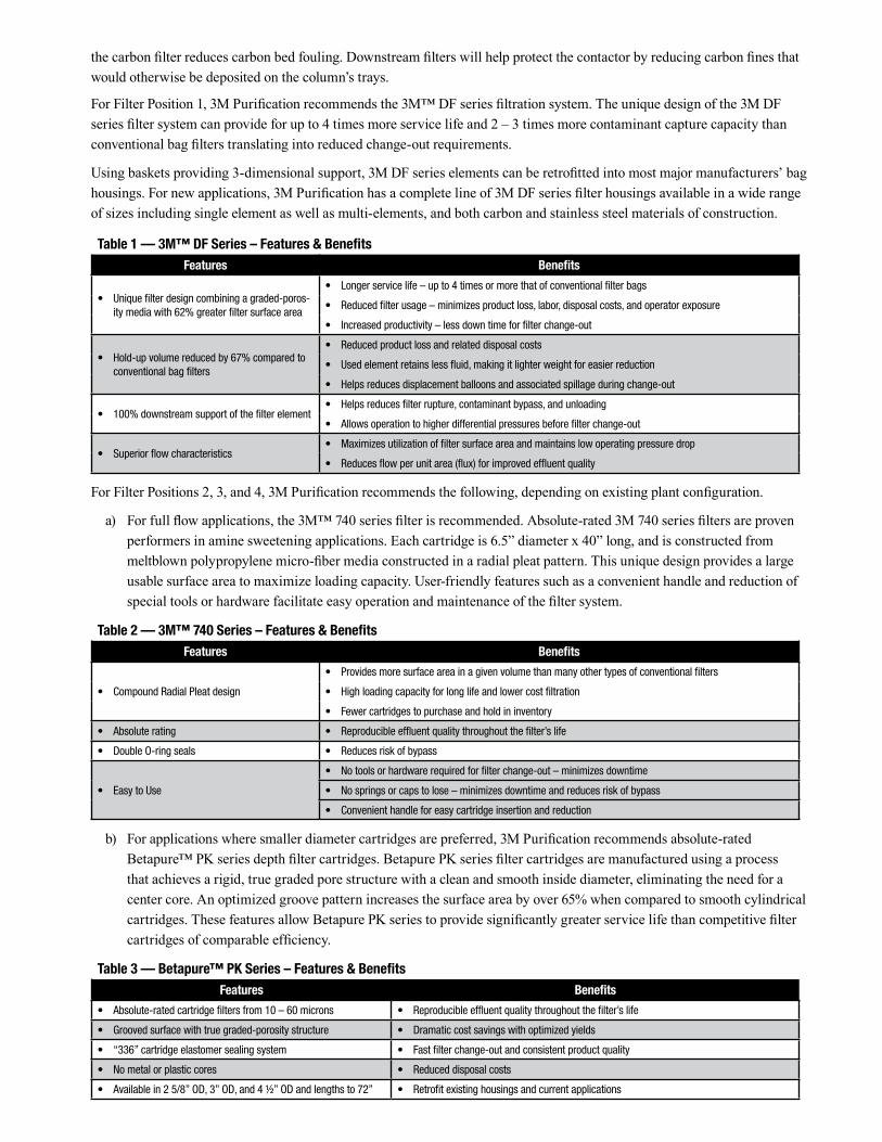
Table 1 — 3M™ DF Series – Features & BenefitsFeatures Benefits
• Uniquefilterdesigncombiningagraded-poros-itymediawith62%greaterfiltersurfacearea
• Longerservicelife–upto4timesormorethatofconventionalfilterbags
• Reducedfilterusage–minimizesproductloss,labor,disposalcosts,andoperatorexposure
• Increasedproductivity–lessdowntimeforfilterchange-out
• Hold-upvolumereducedby67%comparedtoconventionalbagfilters
• Reducedproductlossandrelateddisposalcosts
• Usedelementretainslessfluid,makingitlighterweightforeasierreduction
• Helpsreducesdisplacementballoonsandassociatedspillageduringchange-out
• 100%downstreamsupportofthefilterelement• Helpsreducesfilterrupture,contaminantbypass,andunloading
• Allowsoperationtohigherdifferentialpressuresbeforefilterchange-out
• Superiorflowcharacteristics• Maximizesutilizationoffiltersurfaceareaandmaintainslowoperatingpressuredrop
• Reducesflowperunitarea(flux)forimprovedeffluentquality
For Filter Positions 2, 3, and 4, 3M Purification recommends the following, depending on existing plant configuration.
a) For full flow applications, the 3M™ 740 series filter is recommended. Absolute-rated 3M 740 series filters are proven performers in amine sweetening applications. Each cartridge is 6.5” diameter x 40” long, and is constructed from meltblown polypropylene micro-fiber media constructed in a radial pleat pattern. This unique design provides a large usable surface area to maximize loading capacity. User-friendly features such as a convenient handle and reduction of special tools or hardware facilitate easy operation and maintenance of the filter system.
Table 2 — 3M™ 740 Series – Features & BenefitsFeatures Benefits
• CompoundRadialPleatdesign
• Providesmoresurfaceareainagivenvolumethanmanyothertypesofconventionalfilters
• Highloadingcapacityforlonglifeandlowercostfiltration
• Fewercartridgestopurchaseandholdininventory
• Absoluterating • Reproducibleeffluentqualitythroughoutthefilter’slife
• DoubleO-ringseals • Reducesriskofbypass
• EasytoUse
• Notoolsorhardwarerequiredforfilterchange-out–minimizesdowntime
• Nospringsorcapstolose–minimizesdowntimeandreducesriskofbypass
• Convenienthandleforeasycartridgeinsertionandreduction
b) For applications where smaller diameter cartridges are preferred, 3M Purification recommends absolute-rated Betapure™ PK series depth filter cartridges. Betapure PK series filter cartridges are manufactured using a process that achieves a rigid, true graded pore structure with a clean and smooth inside diameter, eliminating the need for a center core. An optimized groove pattern increases the surface area by over 65% when compared to smooth cylindrical cartridges. These features allow Betapure PK series to provide significantly greater service life than competitive filter cartridges of comparable efficiency.
Table 3 — Betapure™ PK Series – Features & BenefitsFeatures Benefits
• Absolute-ratedcartridgefiltersfrom10–60microns • Reproducibleeffluentqualitythroughoutthefilter’slife
• Groovedsurfacewithtruegraded-porositystructure • Dramaticcostsavingswithoptimizedyields
• “336”cartridgeelastomersealingsystem • Fastfilterchange-outandconsistentproductquality
• Nometalorplasticcores • Reduceddisposalcosts
• Availablein25/8”OD,3”OD,and4½”ODandlengthsto72” • Retrofitexistinghousingsandcurrentapplications

3M Purifi cation Inc.400 Research ParkwayMeriden, CT 06450U.S.A.Phone (800) 243-6894 (203) 237-5541Fax (203) 630-4530www.3Mpurifi cation.com
Important NoticeThe information described in this literature is accurate to the best of our knowledge. A variety of factors, however, can affect the performance of the Product(s) in a particular application, some of which are uniquely within your knowledge and control. INFORMATION IS SUPPLIED UPON THE CONDITION THAT THE PERSONS RECEIVING THE SAME WILL MAKE THEIR OWN DETERMINATION AS TO ITS SUITABILITY FOR THEIR USE. IN NO EVENT WILL 3M PURIFICATION INC. BE RESPONSIBLE FOR DAMAGES OF ANY NATURE WHATSOEVER RESULTING FROM THE USE OF OR RELIANCE UPON INFORMATION.
It is your responsibility to determine if additional testing or information is required and if this product is fi t for a particular purpose and suitable in your specifi c application.
3M PURIFICATION INC. MAKES NO REPRESENTATIONS OR WARRANTIES, EITHER EXPRESS OR IMPLIED INCLUDING WITHOUT LIMITATION ANY WARRANTIES OF MERCHANTABILITY, FITNESS FOR A PARTICULAR PURPOSE OR OF ANY OTHER NATURE HEREUNDER WITH RESPECT TO INFORMATION OR THE PRODUCT TO WHICH INFORMATION REFERS.
Limitation of Liability3M Purifi cation Inc. will not be liable for any loss or damage arising from the use of the Product(s), whether direct, indirect, special, incidental, or consequential, regardless of the legal theory asserted, including warranty, contract, negligence or strict liability. Some states do not allow the exclusion or limitation of incidental or consequential damages, so the above limitation may not apply to you.
ConclusionEfficient reduction of contaminants is critical to proper operation of the tail gas cleanup unit, including protecting process equipment and reducing maintenance costs. The use of 3M™ DF series, 3M™ 740 series, and Betapure™ PK series filters will improve unit efficiency while helping to protect process equipment and reducing overall maintenance costs.
Pleaserecycle.PrintedinU.S.A.3Misatrademarkof3MCompany.
Betapureisatrademarkof 3MCompanyusedunderlicense.
©20113MCompany.Allrightsreserved.70-0202-1062-4REV0911b