Custard Pi 2 - General Purpose input/output board for the ... · Custard Pi 2 - General Purpose...
14
Custard Pi 2 - General Purpose input/output board for the Raspberry Pi GPIO Full Technical Documentation CONTENTS Introduction Circuit Description Schematic Parts List Appendix 1 - Sample Python code for testing digital outputs Appendix 2 - Sample Python code for testing digital inputs Appendix 3 - Sample Python code for testing analogue inputs Appendix 4 - Sample Python code for testing analogue outputs INTRODUCTION The Raspberry Pi GPIO allows the control of external electronics. There are two rows of 13 pins which are brought out to a 26 way header on the edge of the board. The Custard Pi 2 board simply plugs into the Raspberry Pi GPIO connector and provides analogue and digital inputs and outputs. At the same time it protects the Raspberry Pi from possible damage from the wrong voltage being accidentally connected to the GPIO. Custard Pi 2 CIRCUIT DESCRIPTION When the Custard Pi 2 is plugged into the GPIO, two LEDs come ON, showing that the 5V and 3.3V rail are working correctly. GPIO connections showing power rails
Transcript of Custard Pi 2 - General Purpose input/output board for the ... · Custard Pi 2 - General Purpose...

Custard Pi 2 - General Purpose input/output board for the Raspberry Pi GPIO
Full Technical Documentation
CONTENTS
Introduction
Circuit Description
Schematic
Parts List
Appendix 1 - Sample Python code for testing digital outputs
Appendix 2 - Sample Python code for testing digital inputs
Appendix 3 - Sample Python code for testing analogue inputs
Appendix 4 - Sample Python code for testing analogue outputs
INTRODUCTION
The Raspberry Pi GPIO allows the control of external electronics. There are two rows of 13 pins which are brought
out to a 26 way header on the edge of the board. The Custard Pi 2 board simply plugs into the Raspberry Pi GPIO
connector and provides analogue and digital inputs and outputs. At the same time it protects the Raspberry Pi from
possible damage from the wrong voltage being accidentally connected to the GPIO.
Custard Pi 2
CIRCUIT DESCRIPTION
When the Custard Pi 2 is plugged into the GPIO, two LEDs come ON, showing that the 5V and 3.3V rail are working
correctly.
GPIO connections showing power rails

The 3.3V is supplied on pin 1 of the GPIO and the 5V is supplied on pin 2. The 2 LEDs are connected to these pins
with a 1k current limiting resistor. Note that there are no connections to pins 4, 9, 14, 17, 20 & 25 of the GPIO. On
Revision 1 Raspberry Pi boards nothing should be connected to these pins. On Revision 2 boards, these are
connected to 5V, 3.3V or Gnd as shown in the chart below.
Layout of GPIO port pins on Rev 1 and Rev 2 boards
This chart shows the layout of the GPIO port pins. It looks quite complex, but once it is described piece by piece, it
will be easier to understand.
Power pins (J3)
These are brought out to connector J3 on the Custard Pi 2 and have a fuse fitted to each line. This is to prevent the
user from drawing too much current from the Raspberry Pi. The fuses are resettable and are both rated at 0.1 Amp
(100 m Amp).
5V and 3.3V pins with fuses
Open Collector Digital Output pins (J2)
The pins marked green above are general purpose digital input output pins. Pins 11, 12, 13 and 15 are buffered using
a ULN2801 IC and brought out to connector J2.
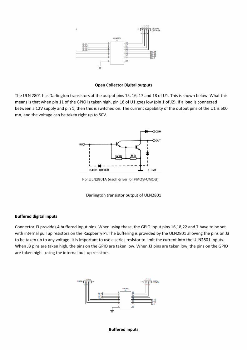
Open Collector Digital outputs
The ULN 2801 has Darlington transistors at the output pins 15, 16, 17 and 18 of U1. This is shown below. What this
means is that when pin 11 of the GPIO is taken high, pin 18 of U1 goes low (pin 1 of J2). If a load is connected
between a 12V supply and pin 1, then this is switched on. The current capability of the output pins of the U1 is 500
mA, and the voltage can be taken right up to 50V.
Darlington transistor output of ULN2801
Buffered digital inputs
Connector J3 provides 4 buffered input pins. When using these, the GPIO input pins 16,18,22 and 7 have to be set
with internal pull up resistors on the Raspberry Pi. The buffering is provided by the ULN2801 allowing the pins on J3
to be taken up to any voltage. It is important to use a series resistor to limit the current into the ULN2801 inputs.
When J3 pins are taken high, the pins on the GPIO are taken low. When J3 pins are taken low, the pins on the GPIO
are taken high - using the internal pull-up resistors.
Buffered inputs

12 bit analogue inputs
Two 12bit input channels are provided by IC U2 which is MCP3202. This is controlled from the GPIO using the SPI
bus. This part of the schematic is shown below.
Analogue input channels
The analogue inputs are protected by two 3.6V zener diodes. Full range is from 0 to 3.3V. Sample Python routine for
reading analogue input signals is provided in the Appendix.
12 bit analogue outputs
Two 12bit output channels are provided by IC U2 which is MCP3202. This is controlled from the GPIO using the SPI
bus. This part of the schematic is shown below.
Analogue output channels

The range of output voltages is from 0 to 3.3V. Sample Python code for setting analogue outputs is provided in the
Appendix.
Notes on the SPI serial bus (J5)
This serial bus is used to interface to a number of external integrated circuits. However it is different from the I2C
bus in that it has separate data out and data in lines and the devices are not addressable. There are separate chip
enable lines for each integrated circuit. The Raspberry Pi SPI bus is provided with 2 chip enable outputs.
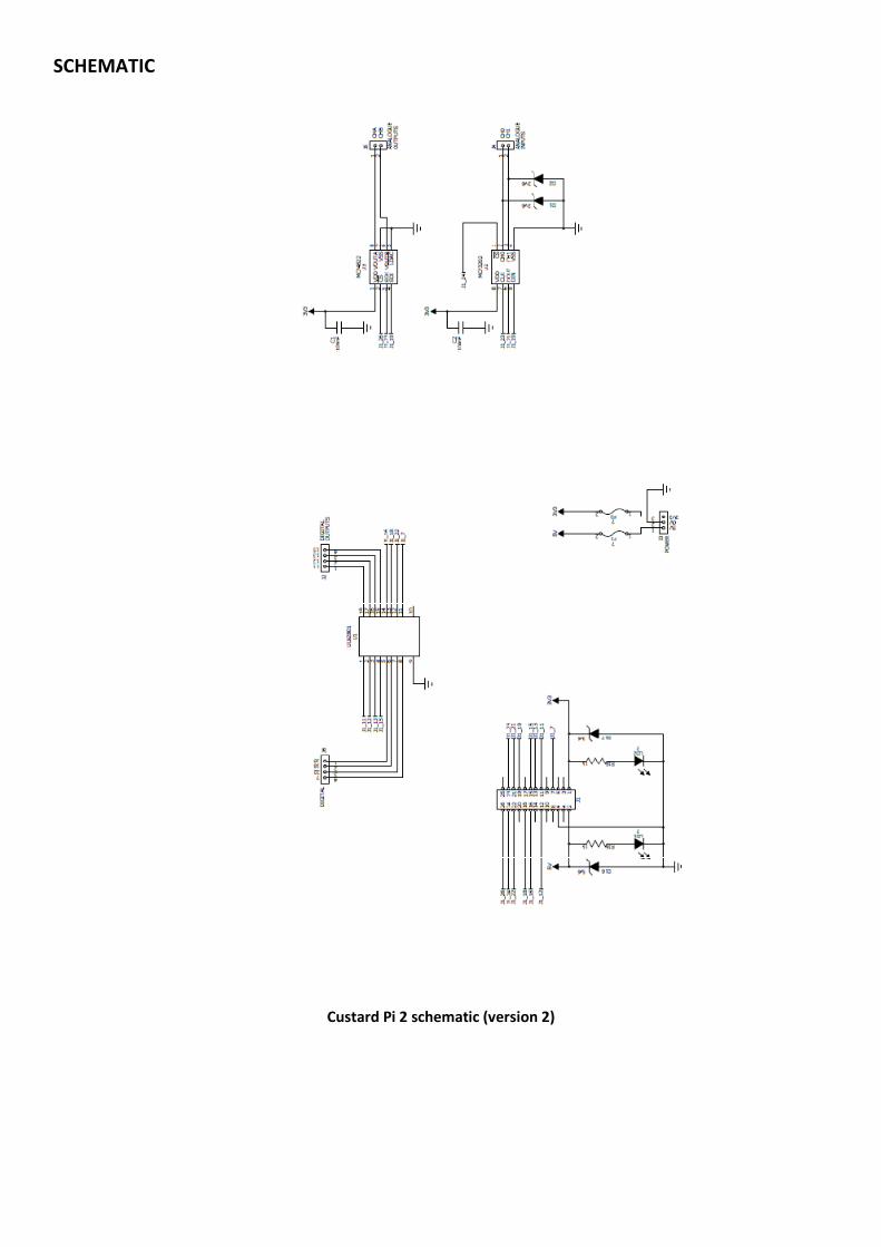
SCHEMATIC
Custard Pi 2 schematic (version 2)

PARTS LIST
Custard Pi -2 General Purpose I/O for the Raspberry Pi
(rev 2b - 25th June 2013)
Description Circuit reference Notes
Printed Circuit Board (PCB)
26 way connector J1 Solder to underside of PCB
ULN2801 U1 Insert the right way round
MCP3202 U2 (static sensitive) Insert the right way round
MCP4822 U3 (static sensitive) Insert the right way round
2 x 2 way screw terminal
connectors
J2 Interlock the two terminals
before soldering with wire access
facing the edge of the PCB.
2 x 2 way screw terminal
connectors
J6 Interlock the two terminals
before soldering with wire access
facing the edge of the PCB.
1 x 3 way screw terminal
connector
J3 Make sure the wire access is
facing the edge of the PCB
2 x 2 way screw terminal
connector
J4,J5 Make sure the wire access is
facing the edge of the PCB
2 x Multifuse F1, F2 Can be inserted either way round
2 x Leds LD1, LD2 Make sure that the longer leg is
inserted into hole marked +
2 x 1k resistors R16 & R18 Can be inserted either way round
3 x 3.6V zener D1, D2 & D17 The black line on the zener has to
line up with the line on the PCB
1 x 5.6V zener D16 The black line on the zener has to
line up with the line on the PCB
2 x 100nF capacitors C1, C2 Can be inserted either way round
2 x sticky pads to isolate the Custard Pi from
Raspberry Pi components

THE CUSTARD PI 2 ASSEMBLY
The positions of the connectors are shown below. These are mini screw terminals into which wires can be quickly
connected.
Positions of the connectors
This is a compact assembly that simply plugs into the Raspberry Pi GPIO. This can be done even with the Raspberry
Pi is powered. Just make sure that the 2 power LEDs are on as soon as you plug in. If not there could be a fault with
the Custard Pi 1 or it has not been plugged in properly.
There is a risk of shorting between the pins on the base of the Custard Pi 2 and some of the components of the
Raspberry Pi, such as the HDMI connector or capacitor C6. For this reason, the Custard Pi is supplied with a length of
double sided sticky pad to act as insulation. If the Custard Pi 2 is bought as a kit of parts for self assembly, then sticky
pads are supplied and must be used.
Sticky pads to insulate Custard Pi 2 from Raspberry Pi

Appendix 1 - Sample Python code for testing digital outputs
#1/usr/bin/env python
#Sample Python code to test digital outputs on Custard Pi 2
#www.sf-innovations.co.uk
#This program sets pins 11, 12, 13 & 15 as outputs.
#Sets them all high
#Waits 0.2 seconds
#Sets them all low
#Waits 0.2 seconds
#Repeats 20 timesimport RPi.GPIO as GPIO
import time
GPIO.setmode(GPIO.BOARD)
GPIO.setup(11, GPIO.OUT)
GPIO.setup(12, GPIO.OUT)
GPIO.setup(13, GPIO.OUT)
GPIO.setup(15, GPIO.OUT)
for x in range (0,20):
GPIO.output(11, True)
GPIO.output(12, True)
GPIO.output(13, True)
GPIO.output(15, True)
time.sleep(0.2)
GPIO.output(11, False)
GPIO.output(12, False)
GPIO.output(13, False)
GPIO.output(15, False)
time.sleep(0.2)
GPIO.cleanup()
import sys
sys.exit()
#TO TEST
#Connect an led to 3.3V, 5V or any voltage up to 50V
#Connect a resistor in series (say 1 kohm) to
#limit the current
#Connect the other side of the resistor to
#Pins 11, 12, 13 or 15 to see it flash.
#Note: When GPIO pin is taken high, the output on the
#Custard Pi goes low (i.e. it is inverted).

Appendix 2 - Sample Python code for testing digital inputs
#1/usr/bin/env python
#sample python code to test digital inputs on Custard Pi 2
#www.sf-innovations.co.uk
#This program sets up pins 7,22,18 & 16
#As inputs with a pull up resistor
#Scans all 4 inputs
#Prints results to screen
#Waits 1 second
#Repeats 10 times
import RPi.GPIO as GPIO
import time
GPIO.setmode(GPIO.BOARD)
GPIO.setup(7, GPIO.IN, pull_up_down=GPIO.PUD_UP)
GPIO.setup(22, GPIO.IN, pull_up_down=GPIO.PUD_UP)
GPIO.setup(18, GPIO.IN, pull_up_down=GPIO.PUD_UP)
GPIO.setup(16, GPIO.IN, pull_up_down=GPIO.PUD_UP)
for x in range (0,10):
bit1=GPIO.input(7)
bit2=GPIO.input(22)
bit3=GPIO.input(18)
bit4=GPIO.input(16)
print bit1, bit2, bit3, bit4
time.sleep(1)
GPIO.cleanup()
import sys
sys.exit()
#TO TEST
#For high, do not connect anything to pin
#(pull up on Raspberry Pi will keep I/P high)
#Revision 1 (no Custard Pi 2 legend on PCB and 4 diodes on the back of the PCB)
#For low link pin to 0 V (ie non-inverting inputs)
#Revision 2 (Custard Pi 2 legend on PCB and no diodes on the back of the PCB).
#For low link pin to 3.3V (ie inverting inputs)
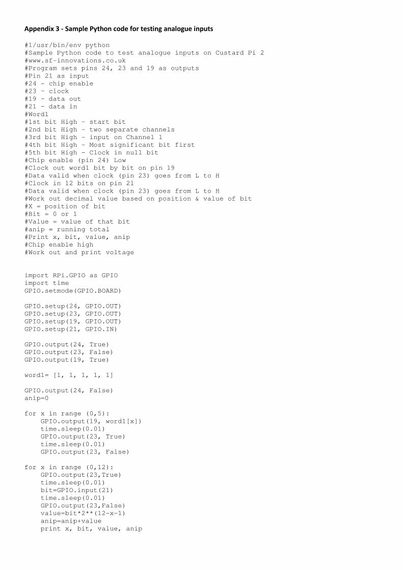
Appendix 3 - Sample Python code for testing analogue inputs
#1/usr/bin/env python
#Sample Python code to test analogue inputs on Custard Pi 2
#www.sf-innovations.co.uk
#Program sets pins 24, 23 and 19 as outputs
#Pin 21 as input
#24 - chip enable
#23 – clock
#19 – data out
#21 – data in
#Word1
#1st bit High – start bit
#2nd bit High – two separate channels
#3rd bit High – input on Channel 1
#4th bit High – Most significant bit first
#5th bit High – Clock in null bit
#Chip enable (pin 24) Low
#Clock out word1 bit by bit on pin 19
#Data valid when clock (pin 23) goes from L to H
#Clock in 12 bits on pin 21
#Data valid when clock (pin 23) goes from L to H
#Work out decimal value based on position & value of bit
#X = position of bit
#Bit = 0 or 1
#Value = value of that bit
#anip = running total
#Print x, bit, value, anip
#Chip enable high
#Work out and print voltage
import RPi.GPIO as GPIO
import time
GPIO.setmode(GPIO.BOARD)
GPIO.setup(24, GPIO.OUT)
GPIO.setup(23, GPIO.OUT)
GPIO.setup(19, GPIO.OUT)
GPIO.setup(21, GPIO.IN)
GPIO.output(24, True)
GPIO.output(23, False)
GPIO.output(19, True)
word1= [1, 1, 1, 1, 1]
GPIO.output(24, False)
anip=0
for x in range (0,5):
GPIO.output(19, word1[x])
time.sleep(0.01)
GPIO.output(23, True)
time.sleep(0.01)
GPIO.output(23, False)
for x in range (0,12):
GPIO.output(23,True)
time.sleep(0.01)
bit=GPIO.input(21)
time.sleep(0.01)
GPIO.output(23,False)
value=bit*2**(12-x-1)
anip=anip+value
print x, bit, value, anip

GPIO.output(24, True)
volt = anip*3.3/4096
print volt
GPIO.cleanup()
import sys
sys.exit()
#TO TEST
#Connect Channel 0 to 3.3V and voltage should be 3.3V
#Connect two equal resistors in series from 3.3V to 0V.
#Connect mid point of resistors to Channel 0 input
#Voltage should be 1.65V

Appendix 4 - Sample Python code for testing analogue outputs
#1/usr/bin/env python
#Sample Python code to test analogue outputs on Custard Pi 2
#www.sf-innovations.co.uk
#Program sets pins 26, 23 and 19 as outputs
#26 - chip enable
#23 – clock
#19 – data out
#Word1
#1st bit High – writing to Channel B
#2nd bit Low – either state is OK
#3rd bit High – when all bits high, V = 2.048V
#4th bit High – output available
#Last 12 bits all High = 4096 = 2.048V
#Word2
#Last 12 bits =011111111111= 2048 = 1.024 V
#Chip enable (pin 26) Low
#Clock out word1 bit by bit on pin 19
#Data valid when clock (pin 23) goes from L to H
#Chip enable High
#This makes analogue voltage available (word 1)
#Wait 5 seconds
#Chip enable Low
#Clock out word2 bit by bit on pin 19
#Data valid when clock (pin 23) goes from L to H
#Chip enable High
#This makes analogue voltage available (word 2)
#Wait 5 seconds
#Repeat 5 times (using variable count)
import RPi.GPIO as GPIO
import time
GPIO.setmode(GPIO.BOARD)
GPIO.setup(26, GPIO.OUT)
GPIO.setup(23, GPIO.OUT)
GPIO.setup(19, GPIO.OUT)
GPIO.output(26, True)
GPIO.output(23, False)
GPIO.output(19, True)
count = 0
word1= [1, 0, 1, 1, 1, 1, 1, 1, 1, 1, 1, 1, 1, 1, 1, 1]
word2= [1, 0, 1, 1, 0, 1, 1, 1, 1, 1, 1, 1, 1, 1, 1, 1]
while count<5:
GPIO.output(26, False)
for x in range (0,16):
GPIO.output(19, word1[x])
print word1[x]
time.sleep(0.01)
GPIO.output(23, True)
time.sleep(0.01)
GPIO.output(23, False)
GPIO.output(26, True)
time.sleep(5)
GPIO.output(26, False)
for x in range (0,16):
GPIO.output(19, word2[x])
print word2[x]
time.sleep(0.01)
GPIO.output(23, True)
time.sleep(0.01)

GPIO.output(23, False)
GPIO.output(26, True)
print count
count = count + 1
time.sleep(5)
GPIO.cleanup()
import sys
sys.exit()
#TO TEST
#Use multi-meter on channel B to see voltage
#cycle from 2V to 1V five times.
End of Document
22nd April 2014